WO2017006802A1 - 報知装置および報知方法 - Google Patents
報知装置および報知方法 Download PDFInfo
- Publication number
- WO2017006802A1 WO2017006802A1 PCT/JP2016/069087 JP2016069087W WO2017006802A1 WO 2017006802 A1 WO2017006802 A1 WO 2017006802A1 JP 2016069087 W JP2016069087 W JP 2016069087W WO 2017006802 A1 WO2017006802 A1 WO 2017006802A1
- Authority
- WO
- WIPO (PCT)
- Prior art keywords
- frequency
- signal
- output
- sweep signal
- notification
- Prior art date
- Legal status (The legal status is an assumption and is not a legal conclusion. Google has not performed a legal analysis and makes no representation as to the accuracy of the status listed.)
- Ceased
Links
Images


Classifications
-
- H—ELECTRICITY
- H04—ELECTRIC COMMUNICATION TECHNIQUE
- H04R—LOUDSPEAKERS, MICROPHONES, GRAMOPHONE PICK-UPS OR LIKE ACOUSTIC ELECTROMECHANICAL TRANSDUCERS; ELECTRIC HEARING AIDS; PUBLIC ADDRESS SYSTEMS
- H04R5/00—Stereophonic arrangements
- H04R5/02—Spatial or constructional arrangements of loudspeakers
- H04R5/023—Spatial or constructional arrangements of loudspeakers in a chair, pillow
-
- B—PERFORMING OPERATIONS; TRANSPORTING
- B60—VEHICLES IN GENERAL
- B60W—CONJOINT CONTROL OF VEHICLE SUB-UNITS OF DIFFERENT TYPE OR DIFFERENT FUNCTION; CONTROL SYSTEMS SPECIALLY ADAPTED FOR HYBRID VEHICLES; ROAD VEHICLE DRIVE CONTROL SYSTEMS FOR PURPOSES NOT RELATED TO THE CONTROL OF A PARTICULAR SUB-UNIT
- B60W50/00—Details of control systems for road vehicle drive control not related to the control of a particular sub-unit, e.g. process diagnostic or vehicle driver interfaces
- B60W50/08—Interaction between the driver and the control system
- B60W50/14—Means for informing the driver, warning the driver or prompting a driver intervention
-
- B—PERFORMING OPERATIONS; TRANSPORTING
- B06—GENERATING OR TRANSMITTING MECHANICAL VIBRATIONS IN GENERAL
- B06B—METHODS OR APPARATUS FOR GENERATING OR TRANSMITTING MECHANICAL VIBRATIONS OF INFRASONIC, SONIC, OR ULTRASONIC FREQUENCY, e.g. FOR PERFORMING MECHANICAL WORK IN GENERAL
- B06B3/00—Methods or apparatus specially adapted for transmitting mechanical vibrations of infrasonic, sonic, or ultrasonic frequency
-
- B—PERFORMING OPERATIONS; TRANSPORTING
- B60—VEHICLES IN GENERAL
- B60N—SEATS SPECIALLY ADAPTED FOR VEHICLES; VEHICLE PASSENGER ACCOMMODATION NOT OTHERWISE PROVIDED FOR
- B60N2/00—Seats specially adapted for vehicles; Arrangement or mounting of seats in vehicles
- B60N2/90—Details or parts not otherwise provided for
-
- B—PERFORMING OPERATIONS; TRANSPORTING
- B60—VEHICLES IN GENERAL
- B60R—VEHICLES, VEHICLE FITTINGS, OR VEHICLE PARTS, NOT OTHERWISE PROVIDED FOR
- B60R11/00—Arrangements for holding or mounting articles, not otherwise provided for
- B60R11/02—Arrangements for holding or mounting articles, not otherwise provided for for radio sets, television sets, telephones, or the like; Arrangement of controls thereof
-
- B—PERFORMING OPERATIONS; TRANSPORTING
- B60—VEHICLES IN GENERAL
- B60W—CONJOINT CONTROL OF VEHICLE SUB-UNITS OF DIFFERENT TYPE OR DIFFERENT FUNCTION; CONTROL SYSTEMS SPECIALLY ADAPTED FOR HYBRID VEHICLES; ROAD VEHICLE DRIVE CONTROL SYSTEMS FOR PURPOSES NOT RELATED TO THE CONTROL OF A PARTICULAR SUB-UNIT
- B60W50/00—Details of control systems for road vehicle drive control not related to the control of a particular sub-unit, e.g. process diagnostic or vehicle driver interfaces
- B60W50/08—Interaction between the driver and the control system
- B60W50/14—Means for informing the driver, warning the driver or prompting a driver intervention
- B60W50/16—Tactile feedback to the driver, e.g. vibration or force feedback to the driver on the steering wheel or the accelerator pedal
-
- G—PHYSICS
- G08—SIGNALLING
- G08G—TRAFFIC CONTROL SYSTEMS
- G08G1/00—Traffic control systems for road vehicles
- G08G1/16—Anti-collision systems
-
- H—ELECTRICITY
- H04—ELECTRIC COMMUNICATION TECHNIQUE
- H04R—LOUDSPEAKERS, MICROPHONES, GRAMOPHONE PICK-UPS OR LIKE ACOUSTIC ELECTROMECHANICAL TRANSDUCERS; ELECTRIC HEARING AIDS; PUBLIC ADDRESS SYSTEMS
- H04R1/00—Details of transducers, loudspeakers or microphones
- H04R1/02—Casings; Cabinets ; Supports therefor; Mountings therein
- H04R1/025—Arrangements for fixing loudspeaker transducers, e.g. in a box, furniture
-
- B—PERFORMING OPERATIONS; TRANSPORTING
- B60—VEHICLES IN GENERAL
- B60R—VEHICLES, VEHICLE FITTINGS, OR VEHICLE PARTS, NOT OTHERWISE PROVIDED FOR
- B60R16/00—Electric or fluid circuits specially adapted for vehicles and not otherwise provided for; Arrangement of elements of electric or fluid circuits specially adapted for vehicles and not otherwise provided for
- B60R16/02—Electric or fluid circuits specially adapted for vehicles and not otherwise provided for; Arrangement of elements of electric or fluid circuits specially adapted for vehicles and not otherwise provided for electric constitutive elements
-
- B—PERFORMING OPERATIONS; TRANSPORTING
- B60—VEHICLES IN GENERAL
- B60T—VEHICLE BRAKE CONTROL SYSTEMS OR PARTS THEREOF; BRAKE CONTROL SYSTEMS OR PARTS THEREOF, IN GENERAL; ARRANGEMENT OF BRAKING ELEMENTS ON VEHICLES IN GENERAL; PORTABLE DEVICES FOR PREVENTING UNWANTED MOVEMENT OF VEHICLES; VEHICLE MODIFICATIONS TO FACILITATE COOLING OF BRAKES
- B60T2201/00—Particular use of vehicle brake systems; Special systems using also the brakes; Special software modules within the brake system controller
- B60T2201/08—Lane monitoring; Lane Keeping Systems
-
- G—PHYSICS
- G08—SIGNALLING
- G08B—SIGNALLING SYSTEMS, e.g. PERSONAL CALLING SYSTEMS; ORDER TELEGRAPHS; ALARM SYSTEMS
- G08B6/00—Tactile signalling systems, e.g. tactile personal calling systems
-
- H—ELECTRICITY
- H04—ELECTRIC COMMUNICATION TECHNIQUE
- H04R—LOUDSPEAKERS, MICROPHONES, GRAMOPHONE PICK-UPS OR LIKE ACOUSTIC ELECTROMECHANICAL TRANSDUCERS; ELECTRIC HEARING AIDS; PUBLIC ADDRESS SYSTEMS
- H04R1/00—Details of transducers, loudspeakers or microphones
- H04R1/02—Casings; Cabinets ; Supports therefor; Mountings therein
- H04R1/028—Casings; Cabinets ; Supports therefor; Mountings therein associated with devices performing functions other than acoustics, e.g. electric candles
-
- H—ELECTRICITY
- H04—ELECTRIC COMMUNICATION TECHNIQUE
- H04R—LOUDSPEAKERS, MICROPHONES, GRAMOPHONE PICK-UPS OR LIKE ACOUSTIC ELECTROMECHANICAL TRANSDUCERS; ELECTRIC HEARING AIDS; PUBLIC ADDRESS SYSTEMS
- H04R2400/00—Loudspeakers
- H04R2400/03—Transducers capable of generating both sound as well as tactile vibration, e.g. as used in cellular phones
-
- H—ELECTRICITY
- H04—ELECTRIC COMMUNICATION TECHNIQUE
- H04R—LOUDSPEAKERS, MICROPHONES, GRAMOPHONE PICK-UPS OR LIKE ACOUSTIC ELECTROMECHANICAL TRANSDUCERS; ELECTRIC HEARING AIDS; PUBLIC ADDRESS SYSTEMS
- H04R2499/00—Aspects covered by H04R or H04S not otherwise provided for in their subgroups
- H04R2499/10—General applications
- H04R2499/13—Acoustic transducers and sound field adaptation in vehicles
-
- H—ELECTRICITY
- H04—ELECTRIC COMMUNICATION TECHNIQUE
- H04R—LOUDSPEAKERS, MICROPHONES, GRAMOPHONE PICK-UPS OR LIKE ACOUSTIC ELECTROMECHANICAL TRANSDUCERS; ELECTRIC HEARING AIDS; PUBLIC ADDRESS SYSTEMS
- H04R3/00—Circuits for transducers
- H04R3/12—Circuits for transducers for distributing signals to two or more loudspeakers
Definitions
- the present invention relates to a notification device and a notification method, and more particularly to a notification device and a notification method that can notify a user by vibration.
- a vehicle alarm device that alerts (notifies) a driver by vibrating a driver's seat when a traveling vehicle deviates from the lane (Patent Document 1, paragraph [0029], FIG. 1 and FIG. 2).
- vibrating bodies are provided on the right side and the left side of the seat surface of the seat. When the vehicle exceeds the right lane, the right vibrating body is vibrated, and when the vehicle exceeds the left lane, the left vibrating body is vibrated.
- the vehicle alarm device disclosed in Patent Document 1 has a structure in which vibration is applied from the thigh to the buttocks and the waist. However, it is not always easy to clearly determine the difference between the left and right monotonous vibrations in the buttocks and the waist.
- a vibration element is provided in the seat frame. For this reason, there is a tendency that resonance occurs in the frame due to the vibration of the vibration element, and there is a possibility that vibration is generated at a position other than the installation position (vibration position) of the vibration element. As a result, vibration is generated at a plurality of positions on the seat, and it is difficult for the driver to identify directional information by vibration even if the vibration generation position is shifted little by little. There was a problem.
- This invention is made
- the notification device is a cushion material portion of a seat and a plurality of exciters installed at different positions of the seat, and in a frequency band in which signals can be output as vibrations by the exciter,
- a sweep signal generator that generates a sweep signal capable of continuously changing the frequency of the vibration by changing the frequency of a predetermined wave at a constant speed, and the sweep signal is changed at a constant speed.
- the sweep signal is changed to a low frequency sweep signal that continuously changes the frequency of the vibration.
- a sweep signal dividing unit that divides, and at least one of the high-frequency sweep signal and the low-frequency sweep signal is output from any one of the exciters, and the high-frequency sweep signal and the high-frequency sweep signal
- a signal output determination unit that determines that at least the other signal of the low-frequency sweep signal is output from any other exciter of the plurality of exciters, The high frequency sweep signal and the low frequency sweep signal are output from one of the determined exciters.
- the notification method of the notification device is a constant within a frequency band in which signals can be output as vibrations by a plurality of exciters installed at different positions on the cushion material portion of the seat.
- the sweep signal generation unit By changing the frequency of the predetermined wave at a speed of, the sweep signal generation unit generates a sweep signal capable of continuously changing the frequency of the vibration, and a constant in the sweep signal A part of the frequency band that varies depending on the speed is defined as the overlap frequency band, and the sweep signal division unit includes a frequency band closer to the high frequency band that includes the overlap frequency band and is equal to or higher than the frequency of the overlap frequency band.
- the frequency of the vibration is continuously changed by changing the frequency of the predetermined wave in a frequency band close to a low frequency including a signal and the frequency of the overlap frequency band that is equal to or lower than the frequency of the overlap frequency band.
- a signal output determination is made to output from any one of the exciters and to determine that at least the other of the high-frequency sweep signal and the low-frequency sweep signal is output from any other exciter of the plurality of exciters.
- an output signal adjustment unit based on the determination by the signal output determination step ,
- the high frequency sweep signal and the low-frequency sweep signal characterized in that an output signal adjustment step of adjusting for outputting from the determined said one of the exciter.
- the high-frequency sweep signal and the low-frequency sweep signal output from the exciter are predetermined waves (for example, within a frequency band in which the exciter can output signals as vibrations). Therefore, the frequency of vibration can be continuously changed. For this reason, by outputting the high-frequency sweep signal and the low-frequency sweep signal from different exciters installed in the seat, it is possible to allow the user to experience vibrations with gradually changing frequencies at different positions of the seat. Furthermore, the signal output determination unit or the output signal adjustment unit determines and adjusts the generation position and generation timing of the vibration of the exciter that outputs the high-frequency sweep signal and the vibration of the exciter that outputs the low-frequency sweep signal. This determination / adjustment makes it possible to perform directional notification.
- the exciter since the exciter is installed in the cushion material portion of the seat, it is possible to prevent the frame of the seat from resonating due to the vibration of the exciter. Furthermore, it is possible to make the user feel the difference in vibration position more reliably.
- the vibration caused by the high-frequency sweep signal and the low-frequency sweep signal is characterized in that the frequency of the vibration changes continuously. Due to this feature, even if either the high-frequency sweep signal or the low-frequency sweep signal is vibrated by any one exciter or is simultaneously vibrated by a plurality of exciters, the vibration change Can be sensed by a change in frequency. Due to the change in vibration accompanying the change in frequency, it is possible to perform notification using vibrations rich in change that are different from monotonous vibrations.
- the frequency band of the frequency changing at a constant speed is different between the high frequency sweep signal and the low frequency sweep signal.
- the user can feel the vibration change.
- the vibration in the overlap frequency band is further emphasized, and the user can be notified. It becomes possible to make it.
- the output signal adjustment unit outputs the high-frequency sweep signal from any one of the plurality of exciters based on the determination of the signal output determination unit, and When outputting a low-frequency sweep signal from any one of the plurality of exciters, the high-frequency sweep signal is started from the high frequency in the high-frequency sweep signal after starting output by the one exciter.
- the high-frequency sweep signal is started from the high frequency in the high-frequency sweep signal after starting output by the one exciter.
- the output from the high frequency sweep signal may be one which terminates at the one exciter.
- the high-frequency sweep signal is output from any one of the plurality of exciters.
- the output signal adjustment unit starts the output by the high-frequency sweep signal in the one exciter, At the timing when the frequency of the predetermined wave that changes at a constant speed from a high frequency to a low frequency in a high frequency sweep signal reaches a frequency within the overlap frequency band, the output of the low frequency sweep signal is the other Start at the exciter of the high and high in the high-frequency sweep signal
- the output of the high-frequency sweep signal is terminated in the one exciter at a timing when the frequency of the predetermined wave that changes at a constant speed from the wave number to a lower frequency deviates from the frequency within the overlap frequency band. It may be.
- the vibration caused by the high-frequency sweep signal and the vibration caused by the low-frequency sweep signal are generated by different exciters so as to produce a time difference. For this reason, it becomes possible to let a user experience vibration generated at different positions at different timings (time differences). Therefore, it becomes possible for the user to experience a more directional notification as vibration.
- the vibration caused by the high frequency sweep signal and the vibration caused by the low frequency sweep signal are output in an overlapped state. For this reason, first, after letting the user experience only the vibration caused by the high-frequency sweep signal, both the high-frequency sweep signal and the low-frequency sweep signal can be sensed together. Finally, only the vibration caused by the low-frequency sweep signal can be experienced. By experiencing such a vibration using the overlap with a time difference, it becomes possible to notify the user with directionality.
- the vibration output by both the high frequency sweep signal and the low frequency sweep signal corresponds to the vibration in the overlap frequency band. Therefore, the frequency is changed in a state in which the vibrations of the two signals of the high frequency sweep signal and the low frequency sweep signal are combined. For this reason, when the vibration of both the high-frequency sweep signal and the low-frequency sweep signal is sensed together, the vibration is further enhanced than when the user feels only the vibration due to the high-frequency sweep signal. This makes it possible to make the vibration change more noticeable. Similarly, the vibration is more attenuated when the user feels only the vibration of the low-frequency sweep signal than when the vibration of both the high-frequency sweep signal and the low-frequency sweep signal are felt together. It becomes possible to feel the change of vibration remarkably.
- the frequency band of the predetermined wave frequency changing at a constant speed in the high frequency sweep signal and the frequency band of the predetermined wave frequency changing at a constant speed in the low frequency sweep signal Is converted to a frequency band in which a signal can be output as sound in the exciter, thereby generating a high frequency sound signal and a low frequency sound signal, and the high frequency sound signal,
- a first adding unit that adds the high-frequency sweep signal to generate a first notification signal; and a second addition signal that generates the second notification signal by adding the low-frequency sound signal and the low-frequency sweep signal.
- An adder, and the signal output determiner receives at least one of the first notification signal and the second notification signal as one of the plurality of exciters.
- the at least one of the first notification signal and the second notification signal is determined to be output from any other exciter of the plurality of exciters, and the output signal adjustment unit is Based on the determination of the signal output determining unit, the first notification signal and the second notification signal may be output from any of the determined exciters.
- the frequency band of the predetermined wave frequency changing at a constant speed in the high frequency sweep signal and the frequency of the predetermined wave changing at a constant speed in the low frequency sweep signal A frequency conversion step in which the frequency converter generates a high-frequency sound signal and a low-frequency sound signal by frequency-converting the frequency band into a frequency band in which a signal can be output as sound in the exciter And adding the high frequency sound signal and the high frequency sweep signal, and a first addition unit generates a first notification signal; the low frequency sound signal and the low frequency sweep signal; And the second addition unit generates a second notification signal, and in the signal output determination step, the signal output determination unit includes the first report At least one of the signal and the second notification signal is output from any one of the exciters, and at least the other signal of the first notification signal and the second notification signal is output. In the output signal adjusting step, the output signal adjusting unit determines that the first notification is made based on the determination in the signal output determining step.
- the frequency band of the high-frequency sweep signal and the frequency band of the low-frequency sweep signal are frequency-converted into a frequency band that allows the signal to be output as sound in the exciter.
- a sound signal and a low-frequency sound signal are generated.
- the generated high frequency sound signal and the high frequency sweep signal are added to generate a first notification signal
- the generated low frequency sound signal and the low frequency sweep signal are added to generate a second notification signal.
- the first notification signal and the second notification signal have both a signal component in the frequency band of the sweep signal that can be output as vibration in the exciter and a signal component in the frequency band of the sound signal that can be output as sound. Therefore, when the first notification signal or the second notification signal is output from the exciter, it is possible to let the user experience both notifications by vibration and sound at a time, and to the user more reliably. Notification can be performed.
- the exciter can output both vibration and sound. For this reason, it is not necessary to prepare a plurality of output devices for vibration and sound by using an exciter to output the notification signal. For this reason, it is possible to output both vibration and sound with only one output device (exciter).
- the output signal adjustment unit causes the first notification signal to be output from any one of the plurality of exciters based on the determination of the signal output determination unit, and the first 2
- the output of the first notification signal is started in the one exciter, and then the high frequency sweep signal is output in the first notification signal.
- the output of the second broadcast signal is output to the other frequency
- the frequency band of the high-frequency sweep signal is decreased from a high frequency to a low frequency in the first notification signal.
- the output of the first notification signal is terminated in the one exciter at a timing when the frequency of the predetermined wave that changes at a constant speed toward the frequency deviates from the frequency within the overlap frequency band. Also good.
- the first notification signal is output from any one of the plurality of exciters based on the determination by the signal output determination step.
- the output signal adjustment unit starts the output by the first notification signal in the one exciter, In the first broadcast signal, the frequency of the predetermined wave that changes at a constant speed from the high frequency to the low frequency in the frequency band of the high-frequency sweep signal reaches the frequency in the overlap frequency band at the timing described above.
- Output by the second notification signal is started in the other exciter, and the first notification signal
- the first notification signal at a timing when the frequency of the predetermined wave that changes at a constant speed from a high frequency to a low frequency in the frequency band of the high-frequency sweep signal deviates from the frequency in the overlap frequency band.
- the output according to may be terminated in the one exciter.
- the vibration / sound by the first notification signal including the high frequency sweep signal and the high frequency sound signal, and the second notification signal including the low frequency sweep signal and the low frequency sound signal are generated by different exciters in a time difference manner. For this reason, it becomes possible to make a user experience the vibration and the sound which generate
- the vibration / sound by the first notification signal and the vibration / sound by the second notification signal are output in an overlapped state. For this reason, first, after letting the user experience only the vibration / sound by the first notification signal, both the vibration / sound of the first notification signal and the second notification signal can be experienced. Finally, the user can experience only the vibration and sound generated by the second notification signal. By making the vibration and sound feel with a time difference using such an overlap, it is possible to notify the user with directionality.
- the signal output determining unit determines which of the plurality of exciters outputs a signal based on the type of alarm signal received from the alarm signal output unit. May be.
- the high frequency sweep signal and the low frequency sweep signal are output from any of the plurality of exciters based on the type of the alarm signal received from the alarm signal output unit, or the first notification Whether to output a signal or a second notification signal is determined. Therefore, by outputting different signals from different exciters according to the type of alarm signal, the timing and pattern at which vibrations and sounds are output can be changed according to the type of alarm signal. In this way, by changing the notification method using vibration or sound according to the type of alarm signal, it becomes possible to make the user recognize the difference in the notification content depending on the notification pattern and timing, and the alarm content can be instantly changed. It becomes possible to make judgment (recognition).
- the exciter may be installed at the left and right positions of the seat seat surface of the seat and at the left and right positions of the backrest portion of the seat.
- the exciter is installed at the left and right positions of the seat seat surface of the seat, and is also installed at the left and right positions of the backrest portion of the seat. For this reason, the user can experience vibration and sound at different parts of the body. In other words, each part of the body can experience changes in the frequency of vibrations and sounds, differences in the timing at which vibrations and sounds are generated (time differences), and differences in locations where vibrations and sounds are generated (exciter installation positions). be able to. Therefore, it is possible to perform directional notification and to make the difference in the alarm content more clearly recognized.
- the high-frequency sweep signal and the low-frequency sweep signal output from the exciter are within a frequency band in which the signal can be output as vibration by the exciter. Since the frequency of the predetermined wave is changed at a constant speed, it is possible to continuously change the vibration frequency. For this reason, by outputting the high-frequency sweep signal and the low-frequency sweep signal from different exciters installed in the seat, it is possible to allow the user to experience vibrations with gradually changing frequencies at different positions of the seat. Furthermore, the signal output decision unit or output signal adjustment unit determines and adjusts the occurrence position and timing of exciter vibrations that output high-frequency sweep signals and exciter vibrations that output low-frequency sweep signals. Thus, it is possible to perform directional notification.
- the exciter is installed in the cushion material portion of the seat. For this reason, it can prevent that the flame
- the vibration caused by the high frequency sweep signal and the low frequency sweep signal is characterized by continuously changing the frequency of the vibration. Due to this feature, even if either the high-frequency sweep signal or the low-frequency sweep signal is vibrated by any one exciter or is simultaneously vibrated by a plurality of exciters, the vibration change Can be sensed by a change in frequency. Due to the change in vibration accompanying the change in frequency, it is possible to perform notification using vibrations rich in change that are different from monotonous vibrations.
- the frequency band of the frequency changing at a constant speed is different between the high frequency sweep signal and the low frequency sweep signal. It becomes possible to sense changes in vibration. Furthermore, since the high frequency sweep signal and the low frequency sweep signal have the same frequency band that can be changed in the overlap frequency band, the vibration in the overlap frequency band can be further emphasized and the notification can be experienced. Is possible.
- FIG. 6 is a diagram schematically showing a state in which speakers EX1 to EX4 according to the embodiment are installed in a driver's seat. It is the figure which showed an example of the sweep signal produced
- FIG. 4 is a diagram illustrating a state in which the sweep signal illustrated in FIG. 3 is divided in the sweep signal dividing unit according to the embodiment, where (a) illustrates the divided first-half sweep signal, and (b) illustrates: The second half of the divided sweep signal is shown.
- FIG. 5 is a diagram showing frequency characteristics of the sweep signal shown in FIGS. 3 and 4 (a) and 4 (b).
- (A) is the 1st frequency conversion part which concerns on embodiment, and shows the frequency characteristic of the signal which performed the frequency conversion process with respect to the division
- (b) is a 2nd frequency conversion part. The frequency characteristic of the signal which performed the frequency conversion process with respect to the division
- (A) is the table
- (B) is the block diagram which showed schematic structure of the frequency extension part which concerns on embodiment. It is the figure which showed the frequency characteristic of the sound signal produced
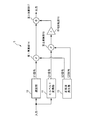
- FIG. 1 is a block diagram showing a schematic configuration of a vehicle alarm device according to the present embodiment.
- a vehicle alarm device (notification device) 1 includes a signal control unit (signal output determination unit) 2, a sweep signal generation unit 3, a sweep signal division unit 4, a first frequency conversion unit (frequency conversion unit) 5, A second frequency converter (frequency converter) 6, a first adder 7, a second adder 8, an output signal adjuster 9, four speakers EX 1, EX 2, EX 3, EX 4 (a plurality of exciters); have.
- the signal control unit 2 outputs a sweep signal generation signal to the sweep signal generation unit 3. Further, the signal control unit 2 outputs a speaker control signal for controlling (adjusting) at which timing of which speaker among the speakers EX1 to EX4 the vibration is generated, to the output signal adjusting unit 9. To do.
- the warning signal output unit 100 is a device that outputs a warning signal such as a lane departure signal, a vehicle approach signal, a dozing detection signal, or a sharp curve signal.
- the lane departure signal is an alarm signal output when the vehicle departs from the lane.
- the vehicle approach signal is an alarm signal that is output when an obstacle (such as a vehicle that is traveling forward or backward) approaches forward or backward.
- a doze detection signal is an alarm signal that is output when a driver's drowsiness is detected by detecting the driver's face angle, blinking interval, or by detecting fluctuations in the center position of the steering wheel. It is.
- the sharp curve signal is an alarm signal that is output when it is detected that there is a sharp curve ahead of the vehicle.
- These alarm targets are detected by a commonly used method such as a method of photographing a vehicle front image and analyzing the image, or a method of detecting a reflected wave by irradiating a radar wave forward. Done.
- the signal control unit 2 When the signal control unit 2 receives an alarm signal from the alarm signal output unit 100, the signal control unit 2 outputs a sweep signal generation signal to the sweep signal generation unit 3. In addition, when the signal control unit 2 receives an alarm signal from the alarm signal output unit 100, the signal control unit 2 instructs the output signal adjustment unit 9 to receive the type of the alarm signal (lane departure signal, vehicle approach signal, doze detection signal, A different speaker control signal is output according to any one of the sharp curve signals. What kind of speaker control signal is output according to the type of the received alarm signal will be described later.
- the speakers EX1 to EX4 notify the driver by outputting vibrations and sounds simultaneously to alert the driver.
- exciters are used as the speakers EX1 to EX4.
- An exciter is an acoustic output device capable of transmitting vibration and sound transmitted from a voice coil to an object in contact with the exciter and using the object as a diaphragm.
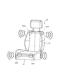
- FIG. 2 is a diagram schematically showing a state in which the speakers EX1 to EX4 are installed in the driver's seat (seat) 20 of the vehicle.
- the speaker EX ⁇ b> 1 is installed at the left front portion of the seat surface portion 21 of the driver seat 20.
- the speaker EX2 is installed in the right front portion of the seat surface portion 21 of the driver seat 20.
- the speaker EX3 is installed in the upper left part of the backrest 22 of the driver's seat 20.
- the speaker EX4 is installed in the upper right portion of the backrest 22 of the driver's seat 20.
- the speakers EX1 to EX4 are installed on a cushion material which is an interior member of the seat surface portion 21 and the backrest portion 22.
- the sweep signal generation unit 3 generates a sine wave sweep signal.
- the sweep signal means a signal obtained by changing the frequency of a predetermined wave continuously at a constant speed from the initial frequency to the target frequency.
- a sine wave is used as an example of the predetermined wave.
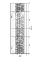
- the sweep signal generation unit 3 receives the sweep signal generation signal from the signal control unit 2, as shown in FIG. 3, the sweep signal has an initial frequency of 120 Hz, a target frequency of 40 Hz, and a sweep time of 1 second.
- a sweep signal in which a wave is swept is generated. Sweep is changing the frequency continuously at a constant speed.
- FIG. 3 shows a case where a sweep signal having one cycle of 1 second is repeatedly generated.
- the generated sweep signal is output to the sweep signal dividing unit 4.
- the initial frequency is 120 Hz and the target frequency is 40 Hz, but this frequency range is not particularly limited.
- the frequency range is not limited as long as it is within a frequency range in which the exciter can output a signal as vibration. It is desirable to use a frequency at which the driver can easily feel the vibration of the exciter if it is in a frequency range in which vibration can be output in the exciter.
- the predetermined wave used for the sweep signal is not necessarily limited to a sine wave. Other waveforms may be shown.
- the sweep signal dividing unit 4 divides the one-cycle sweep signal generated by the sweep signal generating unit 3 into a first half part and a second half part based on the frequency band.
- the frequency range in which the frequency of the sweep signal is changed (for example, a range of 120 Hz to 40 Hz as shown in FIG. 3) is partially overlapped.
- the sweep signal dividing unit 4 divides the sweep signal into a first-half sweep signal (high-frequency sweep signal) and a second-half sweep signal (low-frequency sweep signal).
- the high-frequency sweep signal is a signal in which the frequency of the sine wave is changed in a frequency band near the high frequency that includes the overlap frequency band and is equal to or higher than the frequency of the overlap frequency band.
- the low-frequency sweep signal is a signal in which the frequency of the sine wave is changed in a frequency band near the low frequency that includes the overlap frequency band and is equal to or lower than the frequency of the overlap frequency band.
- the sweep signal generation unit 3 generates a sweep signal with an initial frequency of 120 Hz and a target frequency of 40 Hz. For this reason, the sweep signal is generated by continuously changing the frequency of the sine wave at a constant speed from a high frequency to a low frequency. Therefore, when the frequency of the sine wave changes at a constant speed, the initial frequency becomes a high frequency value, and the frequency value changes to a low value as time passes. Therefore, the first half of the sweep signal is a sweep signal (high frequency sweep signal) having a frequency band closer to the high frequency than the second half of the sweep signal. In addition, the sweep signal in the latter half is a sweep signal (a low-frequency sweep signal) having a frequency band closer to the lower frequency than the sweep signal in the first half.
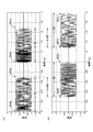
- FIG. 4 is a diagram showing a state where the sweep signal shown in FIG. 3 is divided.
- FIG. 4A shows a divided sweep signal (high-frequency sweep signal) in the first half.
- FIG. 4B shows the divided second half sweep signal (low-frequency sweep signal).
- the first half of the sweep signal (high frequency sweep signal) has an initial frequency of 120 Hz and a target frequency of 64 Hz.
- the second half of the sweep signal (low frequency sweep signal) has an initial frequency of 96 Hz and a target frequency of 40 Hz.
- the sweep time of the sweep signal in the first half is 0.7 seconds
- the sweep time of the sweep signal in the second half is also 0.7 seconds.
- the second half 0.4 seconds of the first half sweep signal and the first half 0.4 seconds of the second half sweep signal overlap.
- the divided sweep signals are shown for two periods (two seconds).
- fade-in processing processing in which the amplitude gradually increases
- fade-out processing processing in which the amplitude gradually decreases
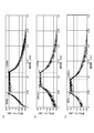
- FIG. 5 is a diagram showing the frequency characteristics of the sweep signal shown in FIGS. 3 and 4 (a) and 4 (b).
- FIG. 5A shows the frequency characteristics of the sweep signal before division shown in FIG.
- FIG. 5B shows frequency characteristics of the first half of the sweep signal (high frequency sweep signal) shown in FIG.
- FIG. 5C shows the frequency characteristics of the second half of the sweep signal (low frequency sweep signal) shown in FIG.
- the gain (signal level) in the sweep range of 40 Hz to 120 Hz shows a high value.
- the gain (signal level) in the sweep range of 64 Hz to 120 Hz shows a high value.
- the gain (signal level) in the sweep range of 40 Hz to 96 Hz shows a high value.
- the first half of the sweep signal (high frequency sweep signal) and the second half of the sweep signal (low frequency sweep signal) are over in the frequency band of 64 Hz to 96 Hz. It turns out that it is divided in a wrapped state.
- the range of 64 Hz to 96 Hz corresponds to the overlap frequency band.
- the overlap frequency band includes the frequency band of the first half of the sweep signal and the frequency band of the second half of the sweep signal.
- the frequency band of the first half of the sweep signal (high frequency sweep signal) shown in FIG. 5B is in the range of 64 Hz to 120 Hz.
- the frequency band of the first half of the sweep signal (high frequency sweep signal) includes the range of 64 Hz to 96 Hz which is the overlap frequency band as described above, and from the frequency band closer to the high frequency than the frequency of the overlap frequency band.
- the first half of the sweep signal (high-frequency sweep signal) is a signal that changes the frequency of the sine wave at a constant speed from a high frequency to a low frequency within a frequency band of 64 Hz to 120 Hz.
- the frequency band of the second half of the sweep signal includes a range of 64 Hz to 96 Hz which is an overlap frequency band, and is composed of a frequency band closer to the lower frequency than the frequency of the overlap frequency band.
- the second half of the sweep signal is a signal that changes the frequency of the sine wave at a constant speed from a high frequency to a low frequency within a frequency band of 40 Hz to 96 Hz.
- the first frequency conversion unit 5 and the second frequency conversion unit 6 generate a higher frequency signal than the sweep signal based on each of the sweep signals divided by the sweep signal division unit 4.
- the first frequency conversion unit 5 receives the divided first-half sweep signal (high-frequency sweep signal) and performs frequency conversion processing.
- the second frequency conversion unit 6 receives the divided second-half sweep signal (low-frequency sweep signal) and performs frequency conversion processing. Since the first frequency conversion unit 5 and the second frequency conversion unit 6 have the same internal configuration and the same processing contents, only the first frequency conversion unit 5 will be described in this embodiment for convenience.
- FIG. 6 is a block diagram showing a schematic configuration of the first frequency converter 5.
- the first frequency conversion unit 5 includes a Hilbert conversion unit 11, a delay unit 12, a sine wave generation unit 13, a first multiplication unit 14, a second multiplication unit 15, a phase inversion unit 16, and a third addition unit. 17.
- the sweep signal divided by the sweep signal dividing unit 4 is input to the Hilbert transform unit 11 and the delay unit 12.
- the divided sweep signal is referred to as a divided sweep signal.
- the divided sweep signal is a name that generically refers to both the first half of the sweep signal and the second half of the sweep signal.
- the Hilbert transform unit 11 generates a Q1 signal that is rotated by 90 degrees with respect to the input divided sweep signal.
- the Hilbert transform unit 11 according to the present embodiment is configured by an FIR (Finite Impulse Response) filter, and sets the filter length to 128 taps.
- the Q1 signal generated by the Hilbert transform unit 11 is output to the second multiplication unit 15.
- the delay unit 12 corrects a delay that occurs in association with the 90-degree phase rotation process in the Hilbert transform unit 11.
- the delay unit 12 generates an I1 signal having a 0-degree phase by performing delay correction on the input divided sweep signal.
- the I1 signal generated by the delay process in the delay unit 12 is output to the first multiplication unit 14.
- the sine wave generator 13 generates an I2 signal composed of a 0 degree phase sine wave and a Q2 signal composed of a 90 degree phase sine wave in accordance with the set conversion frequency.
- the 0 degree phase I2 signal generated by the sine wave generator 13 is output to the first multiplier 14.
- the 90-degree phase Q2 signal generated by the sine wave generator 13 is output to the second multiplier 15.
- the first multiplication unit 14 multiplies the 0 degree phase I1 signal input from the delay unit 12 and the 0 degree phase I2 signal input from the sine wave generation unit 13.
- the signal obtained by performing the multiplication process of the 0 degree phase I1 signal and the 0 degree phase I2 signal in the first multiplier 14 is output to the third adder 17.
- the second multiplying unit 15 multiplies the 90 degree phase rotated Q1 signal input from the Hilbert transforming unit 11 and the 90 degree phase Q2 signal input from the sine wave generating unit 13.
- the signal obtained by multiplying the 90-degree phase Q1 signal and the 90-degree phase Q2 signal in the second multiplication section 15 is output to the phase inversion section 16.
- the phase inversion unit 16 inverts the phase of the input signal.
- the phase inverter 16 inverts the phase of the input signal and then outputs the signal to the third adder 17.
- the third adder 17 receives a signal input from the first multiplier 14 (a signal obtained by multiplying the 0 degree phase I1 signal and the 0 degree phase I2 signal) and the second multiplier 15. (The signal that has undergone phase inversion after the multiplication process of the Q1 signal of 90 degrees and the Q2 signal of 90 degrees) is added. In this way, the signal added by the third adder 17 becomes a signal in which the mirror image is suppressed and a signal obtained by frequency-shifting (frequency converting) the sweep signal to the middle band side.
- FIG. 7A shows frequency characteristics of a signal (high-frequency sound signal) obtained by performing frequency conversion processing on the first half of the sweep signal (high-frequency sweep signal) in the first frequency conversion unit 5.
- FIG. 7B shows the frequency characteristics of a signal (low-frequency sound signal) obtained by performing frequency conversion processing on the second half of the sweep signal (low-frequency sweep signal) in the second frequency converter 6. ing.
- the frequency of the sine wave generated in the sine wave generator 13 is 800 Hz.
- the first half of the sweep signal (frequency range of 64 Hz to 120 Hz) is multiplied by an 800 Hz sine wave.
- the signal (high frequency sound signal) obtained by performing the frequency conversion process on the first half of the sweep signal (high frequency sweep signal) has an initial frequency of 920 Hz (120 Hz + 800 Hz) and a target frequency of 864 Hz (64 Hz + 800 Hz).
- a signal (low frequency sound signal) obtained by performing frequency conversion processing on the second half sweep signal (low frequency sweep signal) has an initial frequency of 896 Hz (96 Hz + 800 Hz) and a target frequency of 840 Hz (40 Hz + 800 Hz).
- the frequency band of the frequency-converted signal is not limited to the above-described range of 840 Hz to 920 Hz.
- the frequency band of the signal subjected to the frequency conversion process is not particularly limited as long as it is a frequency band in which the signals subjected to the frequency conversion process are output as sound in the speakers (exciters) EX1 to EX4.
- the first half of the sweep signal that has been frequency-converted (frequency shifted) by the first frequency converter 5 to the frequency band closer to the mid-range (864 Hz to 920 Hz) is the first half of the sound signal (high-frequency sound signal). It is output to the adder 7.
- the second half of the sweep signal which is frequency-converted (frequency shifted) by the second frequency converter 6 to the frequency band closer to the mid-range (840 Hz to 896 Hz), is the latter half of the sound signal (low-frequency sound signal). ) Is output to the second adder 8.
- the first addition unit 7 includes the first half of the sound signal (high frequency sound signal) input from the first frequency conversion unit 5 and the first half of the sweep signal (high frequency sweep signal) input from the sweep signal dividing unit 4. Addition processing is performed.
- the first half of the sound signal (high frequency sound signal) and the first half of the sweep signal (high frequency sweep signal) subjected to the addition processing in the first addition unit 7 are the first half of the notification signal V1 (first notification signal). It is output to the output signal adjustment unit 9.
- the second adder 8 also includes the second half of the sound signal (low frequency sound signal) input from the second frequency converter 6 and the second half of the sweep signal (low frequency sweep) input from the sweep signal divider 4. Signal).
- the latter half of the sound signal (low frequency sound signal) and the latter half of the sweep signal (low frequency sweep signal) subjected to the addition processing in the second adder 8 are the latter half of the notification signal V2 (second notification signal). It is output to the output signal adjustment unit 9.
- the output signal adjustment unit 9 includes a first half notification signal V1 (first notification signal) input from the first addition unit 7 and a second half notification signal V2 (second notification signal) input from the second addition unit 8. ) Is controlled (adjusted) to which speaker of the speakers EX1 to EX4 is output at which timing based on the speaker control signal received from the signal control unit 2.
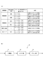
- FIG. 8A shows a combination of the type of the speaker control signal (alarm type) received from the signal control unit 2, the direction of the alarm target with respect to the vehicle (the direction of the alarm target), the speaker that performs the output, and the notification signal. It is the table
- the signal control unit 2 determines from the warning signal whether the deviated lane is on the right side or the left side. . For example, when the deviating lane is the left lane, the signal control unit 2 outputs “notification regarding lane departure” and “information indicating departure from the left lane” as a speaker control signal. The signal is output to the signal adjustment unit 9. Based on the speaker control signal received from the signal control unit 2, the output signal adjustment unit 9 determines that it is “notification about lane departure” and also determines that it is “left lane departure”. When the output signal adjustment unit 9 determines that the deviating lane is on the left side, the output signal adjustment unit 9 first notifies the speaker EX1 (exciter) installed in the left front portion of the seat surface portion 21 of the first half portion. Is output.
- EX1 exciter
- the output of the notification signal V1 in the first half When the output of the notification signal V1 in the first half is started, vibration of 120 Hz and sound of 920 Hz are output from the speaker EX1. Thereafter, the frequency of vibration and sound of the notification signal V1 output from the speaker EX1 gradually decreases at a constant speed (changes at a constant speed from a high frequency to a low frequency). Then, at the timing when the notification signal V1 in the first half is output as vibration of 96 Hz and sound of 896 Hz, the output signal adjustment unit 9 is in the second half with respect to the speaker EX3 (exciter) installed on the upper left side of the backrest portion 22. The partial notification signal V2 is output. When the output of the second half notification signal V2 is started, a vibration of 96 Hz and a sound of 896 Hz are output from the speaker EX3.
- the timing at which the notification signal V1 is output as vibration of 96 Hz refers to the frequency of a sine wave that changes at a constant speed from a higher frequency to a lower frequency in the frequency band of the first half of the sweep signal in the notification signal V1. , Meaning the timing to reach a frequency within the overlap frequency band (96 Hz which is a high frequency in the range of 64 Hz to 96 Hz).
- the vibration and sound frequencies of the notification signal V1 output from the speaker EX1 and the vibration and sound frequencies of the notification signal V2 output from the speaker EX3 gradually decrease. That is, it changes at a constant speed from a high frequency to a low frequency.
- the notification signal V1 is output from the speaker EX1 and the notification signal V2 is notified from the speaker EX3, the notification signal V1 of the first half and the notification signal V2 of the second half overlap, The state is output from the speakers EX1 and EX3.
- the output signal adjustment unit 9 is output from the speaker EX1 installed in the left front portion of the seat surface portion 21.
- the process of outputting the notification signal V1 is finished, and the process of continuously outputting the vibration and sound of the notification signal V2 in the latter half portion is performed only from the speaker EX3 (exciter) installed on the upper left side of the backrest portion 22.
- the timing at which the first half notification signal V1 is output as a vibration of 64 Hz is a sine that changes at a constant speed from a higher frequency to a lower frequency in the frequency band of the first half sweep signal in the notification signal V1. This means the timing at which the wave frequency deviates from the frequency within the overlap frequency band (64 Hz, which is a lower frequency in the range of 64 Hz to 96 Hz).
- the output signal adjustment unit 9 outputs the notification signal V2 from the speaker EX3 installed on the upper left side of the backrest 22 after the notification signal V2 output from the speaker EX3 is output as 40 Hz vibration and 840 Hz sound.
- the notification process described above describes the case where the notification signal V1 in the first half and the notification signal V2 in the second half are performed for one cycle (1 second) of the sweep signal before division.
- the notification process described above is repeatedly executed while the speaker control signal is transmitted from the signal control unit 2.
- the driver is notified using vibration and sound so that the time difference between the notification signal V1 in the first half and the notification signal V2 in the second half is generated. For this reason, it becomes possible for the driver to experience directional vibration / sound by the time difference between the timing at which vibration and sound are output from the speaker EX1 and the timing at which vibration and sound are output from the speaker EX3. . In addition, it is possible to make the driver recognize the difference in the notification content (alarm content) due to directional vibration or the like.
- the notification process is performed in a state where the vibration and sound in the second half of the notification signal V1 output from the speaker EX1 and the vibration and sound in the first half of the notification signal V2 output from the speaker EX3 are overlapped.
- the driver first feels vibration / sound only with the front speaker EX1, and then feels vibration / sound integrally with both the front speaker EX1 and the upper speaker EX3. Vibration and sound can be experienced only by the speaker EX3.
- By causing the driver to feel such vibrations and sounds using the overlap it is possible to further notify the driver with directionality.
- the vibration / sound output from the speakers EX1 and EX3 is configured to notify the driver by gradually changing the frequency. For this reason, even if it is a case where any one vibration and sound of speaker EX1 or EX3 are made to experience, the driver
- the vibration is not only generated by the frequency band of the sweep signal in the notification signal. With the frequency band closer to the middle range of the sound signal, it is possible to output the sound so as to be superimposed on the vibration. For this reason, not only can the driver experience the notification as vibration, but the notification can be recognized by hearing as sound, and the notification can be performed more effectively.
- the signal control unit 2 When the signal control unit 2 receives a warning signal indicating that the vehicle has deviated from the warning signal output unit 100 and the deviating lane is on the right side, the signal control unit 2 outputs the output signal adjustment unit 9. On the other hand, “notification about lane departure” and “information indicating departure from right lane” is output as a speaker control signal. Based on the speaker control signal received from the signal control unit 2, the output signal adjustment unit 9 outputs the vibration and sound of the notification signal V ⁇ b> 1 to the speaker EX ⁇ b> 2 (exciter) installed in the right front portion of the seat surface unit 21. Perform the process. Thereafter, the output signal adjustment unit 9 performs a process of outputting the vibration and sound of the notification signal V2 to the speaker EX4 (exciter) installed on the upper right side of the backrest unit 22.
- the signal control unit 2 controls the output signal adjustment unit 9.
- “Notification of approaching vehicle” and “information indicating that the vehicle is ahead” is output as a speaker control signal.
- the output signal adjustment unit 9 Based on the speaker control signal received from the signal control unit 2, the output signal adjustment unit 9 outputs the vibration and sound of the notification signal V ⁇ b> 1 to the speakers EX ⁇ b> 1 and EX ⁇ b> 2 installed at the left and right front portions of the seat surface unit 21. Process. Thereafter, the output signal adjustment unit 9 performs a process of outputting vibration and sound of the notification signal V2 to the speakers EX3 and EX4 installed on the left and right upper portions of the backrest unit 22.
- the signal control unit 2 controls the output signal adjustment unit 9.
- “notification of approaching vehicle” and “information indicating that the vehicle is behind” is output as a speaker control signal.
- the output signal adjustment unit 9 based on the speaker control signal received from the signal control unit 2, a process for outputting vibration and sound of the notification signal V ⁇ b> 1 to the speakers EX ⁇ b> 3 and EX ⁇ b> 4 installed on the left and right upper portions of the backrest unit 22 I do.
- the output signal adjustment unit 9 performs a process of outputting vibration and sound of the notification signal V2 to the speakers EX1 and EX2 installed in the left and right front portions of the seat surface portion 21.
- the signal control unit 2 receives an alarm signal related to the detection of the driver's nap from the alarm signal output unit 100, the signal control unit 2 notifies the output signal adjustment unit 9 by “notification for detection of dozing”. Information indicating that it is present is output as a speaker control signal. Based on the speaker control signal received from the signal control unit 2, the output signal adjustment unit 9 performs a process of outputting the vibration and sound of the notification signal V1 at the same timing for all the speakers EX1 to EX4.
- the signal control unit 2 receives an alarm signal related to steep curve detection from the alarm signal output unit 100, the signal control unit 2 is “notification for steep curve detection” to the output signal adjustment unit 9. Information to that effect is output as a speaker control signal.
- the output signal adjustment unit 9 Based on the speaker control signal received from the signal control unit 2, the output signal adjustment unit 9 outputs the vibration and sound of the notification signal V ⁇ b> 1 to the speakers EX ⁇ b> 1 and EX ⁇ b> 2 installed at the left and right front portions of the seat surface unit 21. Process. Thereafter, the output signal adjustment unit 9 performs a process of outputting vibration and sound of the notification signal V2 to the speakers EX3 and EX4 installed on the left and right upper portions of the backrest unit 22.
- the driver can sensuously determine what alarm has been notified according to the position of the speaker where vibration and sound are output and the combination thereof, and pay attention. It is possible to determine the direction to be.
- the exciter is installed on the cushioning material of the seat surface portion 21 and the backrest portion 22 to vibrate from a plurality of positions (locations) by resonance. Can be reduced.
- the speakers (exciters) EX1 to EX4 provided on the seat surface portion 21 and the backrest portion 22 perform time division and frequency division for lane departure notification, vehicle approach notification, doze notification, sharp curve notification, and the like.
- the swept signal can be output as vibration. Moreover, it can be made to output as a sound by the midrange sound signal by which the frequency conversion process was carried out. For this reason, it is possible to effectively notify the driver. Furthermore, it becomes possible to notify information with directionality, and it becomes possible to improve the recognition of warnings to the driver.
- the frequency band of the sweep signal to be output as vibration is frequency-converted to the middle frequency band, so that the speakers (exciters) EX1 to EX4 are caused by vibration.
- sound output can be performed as a notification.
- a vibration output device vibration generator
- a sound output device sound reproduction speaker
- the alarm device and the alarm method according to the present invention have been described in detail by using the vehicle alarm device 1 shown in the embodiment as an example.
- the notification device and the notification method according to the present invention are not limited to the examples shown in the embodiments. It is obvious for those skilled in the art that various changes or modifications can be conceived within the scope of the claims, and these are also the same as the vehicle alarm device 1 shown in the embodiment. It is possible to achieve the same effect.
- the notification signal V1 in the first half and the notification signal V2 in the second half are overlapped and output. Since this notification signal output is configured to output not only vibration but also sound, the output of the sound in the first half and the second half overlaps at the time of overlap, thereby doubling the sound gain. Is output. For this reason, at the time of overlap, it is also possible to adopt a configuration that reduces the magnitude (gain) of the notification sound by sound. Thus, by adjusting the gain of the sound at the time of overlap, it is possible to prevent the notification sound from becoming excessively loud. In addition, it is possible to cause the driver to intuitively recognize the directional notification process from the output of the first half of the sound to the output of the second half of the sound in a state in which no sense of incongruity is audibly generated.
- the target frequency in the sweep signal is set to a frequency value higher than the initial frequency, and the frequency of the sine wave is changed from a high frequency to a low frequency at a constant speed (sweep is performed).
- changing the frequency is not limited to changing (sweeping) from a high frequency to a low frequency, and may be a change from a low frequency to a high frequency.
- the direction of the change in the frequency may be any as long as it can provide the driver with a transition feeling due to the change in the frequency.
- the first frequency conversion unit 5 or the second frequency conversion unit 6 multiplies the sweep signal by the 800 Hz sine wave to The sound signal was generated.
- human hearing has logarithmic characteristics, it becomes difficult to sense a sufficient frequency transition (frequency change of the sound signal) when the frequency increases.
- the frequency band for changing the frequency in the sound signal is narrow, there is a tendency that it is difficult to feel a sufficient frequency transition.
- FIG. 8B is a block diagram showing an example of a frequency expansion unit (frequency conversion unit) 30 used in the vehicle alarm device 1 instead of the first frequency conversion unit 5 and the second frequency conversion unit 6. .
- the frequency extension unit 30 extends the frequency and bandwidth of the sweep signal.
- the frequency extension unit 30 includes a squaring unit 31, an HPF (High-pass filter) unit 32, and a gain unit 33.
- the squaring unit 31 squares the first half of the sweep signal (high-frequency sweep signal) or the second half of the sweep signal (low-frequency sweep signal) input from the sweep signal dividing unit 4.
- the sweep signal squared in the squaring unit 31 is doubled in frequency and bandwidth, and converted into a sound signal (a high-frequency sound signal or a low-frequency sound signal) that can be heard as a sound.
- the HPF unit 32 removes the signal output near the DC component (DC component) (near 0 Hz) of the sound signal square-processed by the squaring unit 31.
- the HPF unit 32 removes (reduces) the signal output in the vicinity of the DC component by performing high-pass filter processing on the squared sound signal.
- the gain unit 33 doubles the amplitude of the signal with respect to the sound signal from which the signal output near the DC component has been removed. By performing the process of doubling the amplitude by the gain unit 33, the amplitude of the sound signal can be adjusted so as to have the same amplitude as that of the sweep signal input to the frequency extension unit 30.
- the above-described squaring unit 31, HPF unit 32, and gain unit 33 can be cascade-connected in plural sets as necessary. By cascade-connecting the set of the squaring unit 31, the HPF unit 32, and the gain unit 33, the frequency and bandwidth of the sound signal can be expanded to 2 times, 4 times, 8 times, 16 times, and so on.
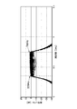
- the second half of the sweep signal (low-frequency sweep signal) shown in FIG. 5C inputs the second half of the sweep signal (low-frequency sweep signal) shown in FIG. 5C to the frequency extension unit 30, and in the frequency extension unit 30, the square unit 31, the HPF unit 32, and The frequency characteristics of a sound signal in which the frequency and the bandwidth are expanded by 8 times by cascading three gain units 33 are shown.
- the second half of the sweep signal (low-frequency sweep signal) shown in FIG. 5C has an initial frequency of 96 Hz and a target frequency of 40 Hz. For this reason, in the frequency characteristics of the signal shown in FIG. 9, the frequency and the bandwidth are expanded by a factor of 8, resulting in a sound signal having an initial frequency of 768H and a target frequency of 320 Hz.
- the sound signal generated in this way is added to the original sweep signal by the first adder 7 and the second adder 8 and output from the speakers EX1 to EX4, thereby generating a low-frequency vibration.
- a sound signal (low-frequency sound signal) that generates a sound whose frequency and bandwidth are expanded by 8 times can be output to the driver.
- the frequency extension unit 30 can increase the amplitude of the mid-range sound signal by eight times compared to the first frequency conversion unit 5 and the second frequency conversion unit 6 shown in FIG. For this reason, it becomes easy for the driver to feel the transition (change) of the frequency of the output sound, and the recognition of the notification signal to the driver can be improved.
- the first frequency conversion unit 5 and the second frequency conversion unit 6 can It is also possible to improve the recognition of the notification signal to the driver by expanding the bandwidth of the sound signal frequency-converted into a region several times.
- the bandwidth of the sound signal shown in FIGS. 7A and 7B is a bandwidth of 80 Hz from 920 Hz to 840 Hz.
- the bandwidth may be expanded so that the bandwidth becomes a bandwidth of 160 Hz or a bandwidth of 320 Hz.
- the frequency band of the sound signal expanded in the frequency expansion unit 30, the frequency band of the sound signal converted in the first frequency conversion unit 5 and the second frequency conversion unit 6, or the bandwidth of the converted sound signal is a frequency band that is different from driving noise (a distinct frequency band in the middle frequency range) so that the notification sound (output of the sound signal) is not masked by the driving noise of the vehicle (it is not difficult to hear). It is desirable to do.
- the frequency expansion unit 30 and the frequency conversion units 5 and 6 may be combined.
- the frequency extension unit 30 and the frequency conversion units 5 and 6 after extending the frequency band by the frequency extension unit 30, the frequency conversion units 5 and 6 can be shifted to an arbitrary mid-range frequency that is not masked by the running sound. It becomes possible to convert the frequency.
- Phase inversion unit 17 (of the first frequency conversion unit or second frequency conversion unit) ... (of the first frequency conversion unit or second frequency conversion unit) 3rd addition part 20 ... driver's seat (seat) 21 ... Seat surface part (of the driver's seat) 22 ... Backrest part (of the driver's seat) 30 ... Frequency extension part (frequency conversion part) 31 ... Square section 32 (of the frequency extension section) ... HPF section 33 (of the frequency extension section) ... Gain section 100 (of the frequency extension section) ... Alarm signal output sections EX1 to EX4 ... Speakers (exciters)
Landscapes
- Engineering & Computer Science (AREA)
- Mechanical Engineering (AREA)
- Automation & Control Theory (AREA)
- Transportation (AREA)
- Physics & Mathematics (AREA)
- Human Computer Interaction (AREA)
- Acoustics & Sound (AREA)
- Signal Processing (AREA)
- Aviation & Aerospace Engineering (AREA)
- General Physics & Mathematics (AREA)
- Details Of Audible-Bandwidth Transducers (AREA)
- Fittings On The Vehicle Exterior For Carrying Loads, And Devices For Holding Or Mounting Articles (AREA)
- Seats For Vehicles (AREA)
- Control Of Driving Devices And Active Controlling Of Vehicle (AREA)
- Circuit For Audible Band Transducer (AREA)
- Traffic Control Systems (AREA)
Priority Applications (3)
| Application Number | Priority Date | Filing Date | Title |
|---|---|---|---|
| EP16821271.0A EP3310071B1 (en) | 2015-07-08 | 2016-06-28 | Notification device and notification method |
| CN201680036003.8A CN107683609B (zh) | 2015-07-08 | 2016-06-28 | 通知装置和通知方法 |
| US15/736,760 US10046773B2 (en) | 2015-07-08 | 2016-06-28 | Notification device and notification method |
Applications Claiming Priority (2)
| Application Number | Priority Date | Filing Date | Title |
|---|---|---|---|
| JP2015-137013 | 2015-07-08 | ||
| JP2015137013A JP6511355B2 (ja) | 2015-07-08 | 2015-07-08 | 報知装置および報知方法 |
Publications (1)
| Publication Number | Publication Date |
|---|---|
| WO2017006802A1 true WO2017006802A1 (ja) | 2017-01-12 |
Family
ID=57685495
Family Applications (1)
| Application Number | Title | Priority Date | Filing Date |
|---|---|---|---|
| PCT/JP2016/069087 Ceased WO2017006802A1 (ja) | 2015-07-08 | 2016-06-28 | 報知装置および報知方法 |
Country Status (5)
| Country | Link |
|---|---|
| US (1) | US10046773B2 (https=) |
| EP (1) | EP3310071B1 (https=) |
| JP (1) | JP6511355B2 (https=) |
| CN (1) | CN107683609B (https=) |
| WO (1) | WO2017006802A1 (https=) |
Cited By (3)
| Publication number | Priority date | Publication date | Assignee | Title |
|---|---|---|---|---|
| WO2019027010A1 (ja) * | 2017-08-04 | 2019-02-07 | クラリオン株式会社 | 車両用警報装置および車両用警報方法 |
| CN110691713A (zh) * | 2017-05-30 | 2020-01-14 | 歌乐株式会社 | 振动产生装置和振动产生方法 |
| WO2020235306A1 (ja) * | 2019-05-17 | 2020-11-26 | 株式会社東海理化電機製作所 | 制御システムおよび提示システム |
Families Citing this family (16)
| Publication number | Priority date | Publication date | Assignee | Title |
|---|---|---|---|---|
| JP6576225B2 (ja) * | 2015-11-27 | 2019-09-18 | クラリオン株式会社 | 車両用報知装置および車両用報知方法 |
| JP6954069B2 (ja) * | 2017-12-08 | 2021-10-27 | トヨタ自動車株式会社 | 車両用注意喚起装置 |
| JP7176187B2 (ja) * | 2017-12-11 | 2022-11-22 | 日産自動車株式会社 | 走行支援方法及び走行支援装置 |
| CN108325806B (zh) * | 2017-12-29 | 2020-08-21 | 瑞声科技(新加坡)有限公司 | 振动信号的生成方法及装置 |
| US10406976B2 (en) * | 2018-01-31 | 2019-09-10 | Ford Global Technologies, Llc | Multi-purpose automotive sound device |
| CN108769871B (zh) * | 2018-05-17 | 2021-07-13 | Oppo广东移动通信有限公司 | 发声方法、装置、电子装置及存储介质 |
| US10748391B2 (en) * | 2018-12-27 | 2020-08-18 | Immersion Corporation | Haptic signal conversion system |
| CN113632152A (zh) * | 2019-03-15 | 2021-11-09 | 本田技研工业株式会社 | 车辆通信装置和程序 |
| JP2020187410A (ja) * | 2019-05-10 | 2020-11-19 | 株式会社東海理化電機製作所 | 注意喚起装置 |
| JP7262314B2 (ja) | 2019-06-05 | 2023-04-21 | フォルシアクラリオン・エレクトロニクス株式会社 | 振動出力装置および振動出力用プログラム |
| US11030863B2 (en) * | 2019-10-02 | 2021-06-08 | Toyota Motor Engineering & Manufacturing North America, Inc. | Systems and methods for providing audio information in a vehicle |
| JP2022119496A (ja) * | 2021-02-04 | 2022-08-17 | 本田技研工業株式会社 | 車両用シートベルト装置 |
| DE102021202168B3 (de) * | 2021-03-05 | 2022-04-28 | Zf Friedrichshafen Ag | Verfahren zum Überwachen eines Fahrzeugs |
| JP7831372B2 (ja) * | 2023-03-30 | 2026-03-17 | トヨタ自動車株式会社 | 報知システム、報知方法、及びコンピュータプログラム |
| FR3153299A1 (fr) * | 2023-09-22 | 2025-03-28 | Psa Automobiles Sa | Procédé et dispositif de contrôle d’un système de rendu sonore embarqué d’un véhicule pour diffusion d’un signal d’alerte |
| EP4672780A1 (en) * | 2024-06-24 | 2025-12-31 | Harman Becker Automotive Systems GmbH | ON-BOARD SPEAKER SYSTEM |
Citations (3)
| Publication number | Priority date | Publication date | Assignee | Title |
|---|---|---|---|---|
| JP2008077631A (ja) * | 2006-08-24 | 2008-04-03 | Toyota Central R&D Labs Inc | シート、車両用シート、及び車両用情報提示装置 |
| JP2009031946A (ja) * | 2007-07-25 | 2009-02-12 | Toyota Central R&D Labs Inc | 情報提示装置 |
| WO2011071044A1 (ja) * | 2009-12-08 | 2011-06-16 | 日本電気株式会社 | 振動子による触刺激を用いた情報提示装置 |
Family Cites Families (23)
| Publication number | Priority date | Publication date | Assignee | Title |
|---|---|---|---|---|
| US6760451B1 (en) * | 1993-08-03 | 2004-07-06 | Peter Graham Craven | Compensating filters |
| WO2002002368A1 (en) * | 2000-07-03 | 2002-01-10 | Med-Dev Limited | Method and apparatus for determining the presence and/or absence and/or a characteristic of an object on a support |
| US7375728B2 (en) * | 2001-10-01 | 2008-05-20 | University Of Minnesota | Virtual mirror |
| US20050149251A1 (en) * | 2000-07-18 | 2005-07-07 | University Of Minnesota | Real time high accuracy geospatial database for onboard intelligent vehicle applications |
| US7245891B2 (en) * | 2003-10-21 | 2007-07-17 | Kyocera Wireless Corp. | Wireless mobile communication device having a speaker vibration alert and method of using same |
| US7681949B2 (en) * | 2006-04-12 | 2010-03-23 | Lear Corporation | Haptic vehicle seat |
| JP4826441B2 (ja) | 2006-11-17 | 2011-11-30 | トヨタ自動車株式会社 | 車両用警告システム |
| JP2008141477A (ja) * | 2006-12-01 | 2008-06-19 | Fujitsu Ten Ltd | 体感音響システム |
| JP2008141465A (ja) * | 2006-12-01 | 2008-06-19 | Fujitsu Ten Ltd | 音場再生システム |
| DE102007031677B4 (de) * | 2007-07-06 | 2010-05-20 | Sda Software Design Ahnert Gmbh | Verfahren und Vorrichtung zum Ermitteln einer raumakustischen Impulsantwort in der Zeitdomäne |
| JP2009039167A (ja) * | 2007-08-06 | 2009-02-26 | Toyota Motor Corp | 眠気判定装置 |
| DE102008040113A1 (de) * | 2008-07-03 | 2010-01-07 | Robert Bosch Gmbh | Fühlbare Fahrerrückmeldung bezüglich der Betriebsbereitschaft eines Fahrzeugs |
| US8339285B2 (en) * | 2009-07-27 | 2012-12-25 | The Boeing Company | Tactile pilot alerting system and method |
| JP5003734B2 (ja) | 2009-08-06 | 2012-08-15 | 株式会社日本自動車部品総合研究所 | 情報提示装置 |
| KR101487694B1 (ko) * | 2009-11-18 | 2015-01-29 | 존슨 컨트롤스 테크놀러지 컴퍼니 | 차량 시트용 햅틱 피드백 시스템 |
| US8217767B2 (en) * | 2010-06-09 | 2012-07-10 | Denso Corporation | Vehicle presence notification apparatus |
| US8804093B2 (en) * | 2011-10-26 | 2014-08-12 | LeVoy Haight | Systems and methods for theater seat movement |
| WO2013091021A1 (en) * | 2011-12-22 | 2013-06-27 | Wolfson Dynamic Hearing Pty Ltd | Method and apparatus for wind noise detection |
| US9493116B2 (en) * | 2012-06-22 | 2016-11-15 | GM Global Technology Operations LLC | Alert systems and methods for a vehicle |
| CN104768821A (zh) * | 2012-11-08 | 2015-07-08 | 丰田自动车株式会社 | 驾驶辅助装置和方法、碰撞预测装置和方法以及通知装置和方法 |
| JP6546535B2 (ja) * | 2013-12-27 | 2019-07-17 | テイ・エス テック株式会社 | シート |
| US9729961B2 (en) * | 2014-11-25 | 2017-08-08 | Bose Corporation | Actively suspended seat with bass loudspeakers |
| KR102484148B1 (ko) * | 2015-06-03 | 2023-01-03 | 클리어모션, 아이엔씨. | 차체 모션 및 승객 경험을 제어하기 위한 방법 및 시스템 |
-
2015
- 2015-07-08 JP JP2015137013A patent/JP6511355B2/ja active Active
-
2016
- 2016-06-28 CN CN201680036003.8A patent/CN107683609B/zh active Active
- 2016-06-28 US US15/736,760 patent/US10046773B2/en active Active
- 2016-06-28 EP EP16821271.0A patent/EP3310071B1/en active Active
- 2016-06-28 WO PCT/JP2016/069087 patent/WO2017006802A1/ja not_active Ceased
Patent Citations (3)
| Publication number | Priority date | Publication date | Assignee | Title |
|---|---|---|---|---|
| JP2008077631A (ja) * | 2006-08-24 | 2008-04-03 | Toyota Central R&D Labs Inc | シート、車両用シート、及び車両用情報提示装置 |
| JP2009031946A (ja) * | 2007-07-25 | 2009-02-12 | Toyota Central R&D Labs Inc | 情報提示装置 |
| WO2011071044A1 (ja) * | 2009-12-08 | 2011-06-16 | 日本電気株式会社 | 振動子による触刺激を用いた情報提示装置 |
Non-Patent Citations (1)
| Title |
|---|
| See also references of EP3310071A4 * |
Cited By (5)
| Publication number | Priority date | Publication date | Assignee | Title |
|---|---|---|---|---|
| CN110691713A (zh) * | 2017-05-30 | 2020-01-14 | 歌乐株式会社 | 振动产生装置和振动产生方法 |
| CN110691713B (zh) * | 2017-05-30 | 2022-01-21 | 歌乐株式会社 | 振动产生装置和振动产生方法 |
| WO2019027010A1 (ja) * | 2017-08-04 | 2019-02-07 | クラリオン株式会社 | 車両用警報装置および車両用警報方法 |
| EP3647149A4 (en) * | 2017-08-04 | 2020-08-12 | Clarion Co., Ltd. | VEHICLE ALARM DEVICE AND VEHICLE ALARM PROCESS |
| WO2020235306A1 (ja) * | 2019-05-17 | 2020-11-26 | 株式会社東海理化電機製作所 | 制御システムおよび提示システム |
Also Published As
| Publication number | Publication date |
|---|---|
| EP3310071A1 (en) | 2018-04-18 |
| JP2017021476A (ja) | 2017-01-26 |
| US10046773B2 (en) | 2018-08-14 |
| CN107683609B (zh) | 2019-08-30 |
| JP6511355B2 (ja) | 2019-05-15 |
| US20180170229A1 (en) | 2018-06-21 |
| EP3310071A4 (en) | 2019-02-27 |
| CN107683609A (zh) | 2018-02-09 |
| EP3310071B1 (en) | 2021-04-14 |
Similar Documents
| Publication | Publication Date | Title |
|---|---|---|
| JP6511355B2 (ja) | 報知装置および報知方法 | |
| JP6338425B2 (ja) | 振動音響装置、振動音響出力方法および振動音響プログラム | |
| CN108290510B (zh) | 车辆用通知装置和车辆用通知方法 | |
| JP2017021476A5 (https=) | ||
| JP6216553B2 (ja) | 伝搬遅延補正装置及び伝搬遅延補正方法 | |
| JP3533092B2 (ja) | オーディオシステム | |
| US20150319549A1 (en) | Sound field adjustment filter, sound field adjustment apparatus and sound field adjustment method | |
| CN110997444A (zh) | 车辆用警报装置和车辆用警报方法 | |
| CN105764774B (zh) | 以可配置的距离线索生成音频信号 | |
| WO2018189713A3 (en) | Vehicular acoustic environmental system | |
| JP2009040317A (ja) | 車両接近告知装置 | |
| WO2017006794A1 (ja) | 報知装置および報知方法 | |
| JP2015231063A (ja) | 車載音響装置 | |
| JP2005109969A (ja) | オーディオシステム | |
| JP6584609B2 (ja) | 報知装置および報知方法 | |
| JP6568020B2 (ja) | 音響装置 | |
| WO2023221955A1 (zh) | 车载音效系统和车载音效处理方法 | |
| JP2013242232A (ja) | 物体の接近監視装置 | |
| JP2011228956A (ja) | 車載用音場制御装置 | |
| JP2019080127A (ja) | 報知装置および報知方法 | |
| JP2008245159A (ja) | 音響信号発生装置および方法 | |
| JP2025169687A (ja) | 情報通知装置、情報通知プログラム、情報通知方法、および情報通知システム | |
| JP2017224167A (ja) | 車両用方向提示装置 | |
| JP6084049B2 (ja) | フィルタ制御装置及びフィルタ制御方法 | |
| JPS5818400Y2 (ja) | 音響再生装置 |
Legal Events
| Date | Code | Title | Description |
|---|---|---|---|
| 121 | Ep: the epo has been informed by wipo that ep was designated in this application |
Ref document number: 16821271 Country of ref document: EP Kind code of ref document: A1 |
|
| WWE | Wipo information: entry into national phase |
Ref document number: 15736760 Country of ref document: US |
|
| NENP | Non-entry into the national phase |
Ref country code: DE |
|
| WWE | Wipo information: entry into national phase |
Ref document number: 2016821271 Country of ref document: EP |