WO2017006802A1 - Notification device and notification method - Google Patents
Notification device and notification method Download PDFInfo
- Publication number
- WO2017006802A1 WO2017006802A1 PCT/JP2016/069087 JP2016069087W WO2017006802A1 WO 2017006802 A1 WO2017006802 A1 WO 2017006802A1 JP 2016069087 W JP2016069087 W JP 2016069087W WO 2017006802 A1 WO2017006802 A1 WO 2017006802A1
- Authority
- WO
- WIPO (PCT)
- Prior art keywords
- frequency
- signal
- output
- sweep signal
- notification
- Prior art date
Links
Images


Classifications
-
- H—ELECTRICITY
- H04—ELECTRIC COMMUNICATION TECHNIQUE
- H04R—LOUDSPEAKERS, MICROPHONES, GRAMOPHONE PICK-UPS OR LIKE ACOUSTIC ELECTROMECHANICAL TRANSDUCERS; DEAF-AID SETS; PUBLIC ADDRESS SYSTEMS
- H04R5/00—Stereophonic arrangements
- H04R5/02—Spatial or constructional arrangements of loudspeakers
- H04R5/023—Spatial or constructional arrangements of loudspeakers in a chair, pillow
-
- B—PERFORMING OPERATIONS; TRANSPORTING
- B60—VEHICLES IN GENERAL
- B60W—CONJOINT CONTROL OF VEHICLE SUB-UNITS OF DIFFERENT TYPE OR DIFFERENT FUNCTION; CONTROL SYSTEMS SPECIALLY ADAPTED FOR HYBRID VEHICLES; ROAD VEHICLE DRIVE CONTROL SYSTEMS FOR PURPOSES NOT RELATED TO THE CONTROL OF A PARTICULAR SUB-UNIT
- B60W50/00—Details of control systems for road vehicle drive control not related to the control of a particular sub-unit, e.g. process diagnostic or vehicle driver interfaces
- B60W50/08—Interaction between the driver and the control system
- B60W50/14—Means for informing the driver, warning the driver or prompting a driver intervention
-
- B—PERFORMING OPERATIONS; TRANSPORTING
- B06—GENERATING OR TRANSMITTING MECHANICAL VIBRATIONS IN GENERAL
- B06B—METHODS OR APPARATUS FOR GENERATING OR TRANSMITTING MECHANICAL VIBRATIONS OF INFRASONIC, SONIC, OR ULTRASONIC FREQUENCY, e.g. FOR PERFORMING MECHANICAL WORK IN GENERAL
- B06B3/00—Methods or apparatus specially adapted for transmitting mechanical vibrations of infrasonic, sonic, or ultrasonic frequency
-
- B—PERFORMING OPERATIONS; TRANSPORTING
- B60—VEHICLES IN GENERAL
- B60N—SEATS SPECIALLY ADAPTED FOR VEHICLES; VEHICLE PASSENGER ACCOMMODATION NOT OTHERWISE PROVIDED FOR
- B60N2/00—Seats specially adapted for vehicles; Arrangement or mounting of seats in vehicles
- B60N2/90—Details or parts not otherwise provided for
-
- B—PERFORMING OPERATIONS; TRANSPORTING
- B60—VEHICLES IN GENERAL
- B60R—VEHICLES, VEHICLE FITTINGS, OR VEHICLE PARTS, NOT OTHERWISE PROVIDED FOR
- B60R11/00—Arrangements for holding or mounting articles, not otherwise provided for
- B60R11/02—Arrangements for holding or mounting articles, not otherwise provided for for radio sets, television sets, telephones, or the like; Arrangement of controls thereof
-
- B—PERFORMING OPERATIONS; TRANSPORTING
- B60—VEHICLES IN GENERAL
- B60W—CONJOINT CONTROL OF VEHICLE SUB-UNITS OF DIFFERENT TYPE OR DIFFERENT FUNCTION; CONTROL SYSTEMS SPECIALLY ADAPTED FOR HYBRID VEHICLES; ROAD VEHICLE DRIVE CONTROL SYSTEMS FOR PURPOSES NOT RELATED TO THE CONTROL OF A PARTICULAR SUB-UNIT
- B60W50/00—Details of control systems for road vehicle drive control not related to the control of a particular sub-unit, e.g. process diagnostic or vehicle driver interfaces
- B60W50/08—Interaction between the driver and the control system
- B60W50/14—Means for informing the driver, warning the driver or prompting a driver intervention
- B60W50/16—Tactile feedback to the driver, e.g. vibration or force feedback to the driver on the steering wheel or the accelerator pedal
-
- G—PHYSICS
- G08—SIGNALLING
- G08G—TRAFFIC CONTROL SYSTEMS
- G08G1/00—Traffic control systems for road vehicles
- G08G1/16—Anti-collision systems
-
- H—ELECTRICITY
- H04—ELECTRIC COMMUNICATION TECHNIQUE
- H04R—LOUDSPEAKERS, MICROPHONES, GRAMOPHONE PICK-UPS OR LIKE ACOUSTIC ELECTROMECHANICAL TRANSDUCERS; DEAF-AID SETS; PUBLIC ADDRESS SYSTEMS
- H04R1/00—Details of transducers, loudspeakers or microphones
- H04R1/02—Casings; Cabinets ; Supports therefor; Mountings therein
- H04R1/025—Arrangements for fixing loudspeaker transducers, e.g. in a box, furniture
-
- B—PERFORMING OPERATIONS; TRANSPORTING
- B60—VEHICLES IN GENERAL
- B60R—VEHICLES, VEHICLE FITTINGS, OR VEHICLE PARTS, NOT OTHERWISE PROVIDED FOR
- B60R16/00—Electric or fluid circuits specially adapted for vehicles and not otherwise provided for; Arrangement of elements of electric or fluid circuits specially adapted for vehicles and not otherwise provided for
- B60R16/02—Electric or fluid circuits specially adapted for vehicles and not otherwise provided for; Arrangement of elements of electric or fluid circuits specially adapted for vehicles and not otherwise provided for electric constitutive elements
-
- B—PERFORMING OPERATIONS; TRANSPORTING
- B60—VEHICLES IN GENERAL
- B60T—VEHICLE BRAKE CONTROL SYSTEMS OR PARTS THEREOF; BRAKE CONTROL SYSTEMS OR PARTS THEREOF, IN GENERAL; ARRANGEMENT OF BRAKING ELEMENTS ON VEHICLES IN GENERAL; PORTABLE DEVICES FOR PREVENTING UNWANTED MOVEMENT OF VEHICLES; VEHICLE MODIFICATIONS TO FACILITATE COOLING OF BRAKES
- B60T2201/00—Particular use of vehicle brake systems; Special systems using also the brakes; Special software modules within the brake system controller
- B60T2201/08—Lane monitoring; Lane Keeping Systems
-
- G—PHYSICS
- G08—SIGNALLING
- G08B—SIGNALLING OR CALLING SYSTEMS; ORDER TELEGRAPHS; ALARM SYSTEMS
- G08B6/00—Tactile signalling systems, e.g. personal calling systems
-
- H—ELECTRICITY
- H04—ELECTRIC COMMUNICATION TECHNIQUE
- H04R—LOUDSPEAKERS, MICROPHONES, GRAMOPHONE PICK-UPS OR LIKE ACOUSTIC ELECTROMECHANICAL TRANSDUCERS; DEAF-AID SETS; PUBLIC ADDRESS SYSTEMS
- H04R1/00—Details of transducers, loudspeakers or microphones
- H04R1/02—Casings; Cabinets ; Supports therefor; Mountings therein
- H04R1/028—Casings; Cabinets ; Supports therefor; Mountings therein associated with devices performing functions other than acoustics, e.g. electric candles
-
- H—ELECTRICITY
- H04—ELECTRIC COMMUNICATION TECHNIQUE
- H04R—LOUDSPEAKERS, MICROPHONES, GRAMOPHONE PICK-UPS OR LIKE ACOUSTIC ELECTROMECHANICAL TRANSDUCERS; DEAF-AID SETS; PUBLIC ADDRESS SYSTEMS
- H04R2400/00—Loudspeakers
- H04R2400/03—Transducers capable of generating both sound as well as tactile vibration, e.g. as used in cellular phones
-
- H—ELECTRICITY
- H04—ELECTRIC COMMUNICATION TECHNIQUE
- H04R—LOUDSPEAKERS, MICROPHONES, GRAMOPHONE PICK-UPS OR LIKE ACOUSTIC ELECTROMECHANICAL TRANSDUCERS; DEAF-AID SETS; PUBLIC ADDRESS SYSTEMS
- H04R2499/00—Aspects covered by H04R or H04S not otherwise provided for in their subgroups
- H04R2499/10—General applications
- H04R2499/13—Acoustic transducers and sound field adaptation in vehicles
-
- H—ELECTRICITY
- H04—ELECTRIC COMMUNICATION TECHNIQUE
- H04R—LOUDSPEAKERS, MICROPHONES, GRAMOPHONE PICK-UPS OR LIKE ACOUSTIC ELECTROMECHANICAL TRANSDUCERS; DEAF-AID SETS; PUBLIC ADDRESS SYSTEMS
- H04R3/00—Circuits for transducers, loudspeakers or microphones
- H04R3/12—Circuits for transducers, loudspeakers or microphones for distributing signals to two or more loudspeakers
Definitions
- the present invention relates to a notification device and a notification method, and more particularly to a notification device and a notification method that can notify a user by vibration.
- a vehicle alarm device that alerts (notifies) a driver by vibrating a driver's seat when a traveling vehicle deviates from the lane (Patent Document 1, paragraph [0029], FIG. 1 and FIG. 2).
- vibrating bodies are provided on the right side and the left side of the seat surface of the seat. When the vehicle exceeds the right lane, the right vibrating body is vibrated, and when the vehicle exceeds the left lane, the left vibrating body is vibrated.
- the vehicle alarm device disclosed in Patent Document 1 has a structure in which vibration is applied from the thigh to the buttocks and the waist. However, it is not always easy to clearly determine the difference between the left and right monotonous vibrations in the buttocks and the waist.
- a vibration element is provided in the seat frame. For this reason, there is a tendency that resonance occurs in the frame due to the vibration of the vibration element, and there is a possibility that vibration is generated at a position other than the installation position (vibration position) of the vibration element. As a result, vibration is generated at a plurality of positions on the seat, and it is difficult for the driver to identify directional information by vibration even if the vibration generation position is shifted little by little. There was a problem.
- This invention is made
- the notification device is a cushion material portion of a seat and a plurality of exciters installed at different positions of the seat, and in a frequency band in which signals can be output as vibrations by the exciter,
- a sweep signal generator that generates a sweep signal capable of continuously changing the frequency of the vibration by changing the frequency of a predetermined wave at a constant speed, and the sweep signal is changed at a constant speed.
- the sweep signal is changed to a low frequency sweep signal that continuously changes the frequency of the vibration.
- a sweep signal dividing unit that divides, and at least one of the high-frequency sweep signal and the low-frequency sweep signal is output from any one of the exciters, and the high-frequency sweep signal and the high-frequency sweep signal
- a signal output determination unit that determines that at least the other signal of the low-frequency sweep signal is output from any other exciter of the plurality of exciters, The high frequency sweep signal and the low frequency sweep signal are output from one of the determined exciters.
- the notification method of the notification device is a constant within a frequency band in which signals can be output as vibrations by a plurality of exciters installed at different positions on the cushion material portion of the seat.
- the sweep signal generation unit By changing the frequency of the predetermined wave at a speed of, the sweep signal generation unit generates a sweep signal capable of continuously changing the frequency of the vibration, and a constant in the sweep signal A part of the frequency band that varies depending on the speed is defined as the overlap frequency band, and the sweep signal division unit includes a frequency band closer to the high frequency band that includes the overlap frequency band and is equal to or higher than the frequency of the overlap frequency band.
- the frequency of the vibration is continuously changed by changing the frequency of the predetermined wave in a frequency band close to a low frequency including a signal and the frequency of the overlap frequency band that is equal to or lower than the frequency of the overlap frequency band.
- a signal output determination is made to output from any one of the exciters and to determine that at least the other of the high-frequency sweep signal and the low-frequency sweep signal is output from any other exciter of the plurality of exciters.
- an output signal adjustment unit based on the determination by the signal output determination step ,
- the high frequency sweep signal and the low-frequency sweep signal characterized in that an output signal adjustment step of adjusting for outputting from the determined said one of the exciter.
- the high-frequency sweep signal and the low-frequency sweep signal output from the exciter are predetermined waves (for example, within a frequency band in which the exciter can output signals as vibrations). Therefore, the frequency of vibration can be continuously changed. For this reason, by outputting the high-frequency sweep signal and the low-frequency sweep signal from different exciters installed in the seat, it is possible to allow the user to experience vibrations with gradually changing frequencies at different positions of the seat. Furthermore, the signal output determination unit or the output signal adjustment unit determines and adjusts the generation position and generation timing of the vibration of the exciter that outputs the high-frequency sweep signal and the vibration of the exciter that outputs the low-frequency sweep signal. This determination / adjustment makes it possible to perform directional notification.
- the exciter since the exciter is installed in the cushion material portion of the seat, it is possible to prevent the frame of the seat from resonating due to the vibration of the exciter. Furthermore, it is possible to make the user feel the difference in vibration position more reliably.
- the vibration caused by the high-frequency sweep signal and the low-frequency sweep signal is characterized in that the frequency of the vibration changes continuously. Due to this feature, even if either the high-frequency sweep signal or the low-frequency sweep signal is vibrated by any one exciter or is simultaneously vibrated by a plurality of exciters, the vibration change Can be sensed by a change in frequency. Due to the change in vibration accompanying the change in frequency, it is possible to perform notification using vibrations rich in change that are different from monotonous vibrations.
- the frequency band of the frequency changing at a constant speed is different between the high frequency sweep signal and the low frequency sweep signal.
- the user can feel the vibration change.
- the vibration in the overlap frequency band is further emphasized, and the user can be notified. It becomes possible to make it.
- the output signal adjustment unit outputs the high-frequency sweep signal from any one of the plurality of exciters based on the determination of the signal output determination unit, and When outputting a low-frequency sweep signal from any one of the plurality of exciters, the high-frequency sweep signal is started from the high frequency in the high-frequency sweep signal after starting output by the one exciter.
- the high-frequency sweep signal is started from the high frequency in the high-frequency sweep signal after starting output by the one exciter.
- the output from the high frequency sweep signal may be one which terminates at the one exciter.
- the high-frequency sweep signal is output from any one of the plurality of exciters.
- the output signal adjustment unit starts the output by the high-frequency sweep signal in the one exciter, At the timing when the frequency of the predetermined wave that changes at a constant speed from a high frequency to a low frequency in a high frequency sweep signal reaches a frequency within the overlap frequency band, the output of the low frequency sweep signal is the other Start at the exciter of the high and high in the high-frequency sweep signal
- the output of the high-frequency sweep signal is terminated in the one exciter at a timing when the frequency of the predetermined wave that changes at a constant speed from the wave number to a lower frequency deviates from the frequency within the overlap frequency band. It may be.
- the vibration caused by the high-frequency sweep signal and the vibration caused by the low-frequency sweep signal are generated by different exciters so as to produce a time difference. For this reason, it becomes possible to let a user experience vibration generated at different positions at different timings (time differences). Therefore, it becomes possible for the user to experience a more directional notification as vibration.
- the vibration caused by the high frequency sweep signal and the vibration caused by the low frequency sweep signal are output in an overlapped state. For this reason, first, after letting the user experience only the vibration caused by the high-frequency sweep signal, both the high-frequency sweep signal and the low-frequency sweep signal can be sensed together. Finally, only the vibration caused by the low-frequency sweep signal can be experienced. By experiencing such a vibration using the overlap with a time difference, it becomes possible to notify the user with directionality.
- the vibration output by both the high frequency sweep signal and the low frequency sweep signal corresponds to the vibration in the overlap frequency band. Therefore, the frequency is changed in a state in which the vibrations of the two signals of the high frequency sweep signal and the low frequency sweep signal are combined. For this reason, when the vibration of both the high-frequency sweep signal and the low-frequency sweep signal is sensed together, the vibration is further enhanced than when the user feels only the vibration due to the high-frequency sweep signal. This makes it possible to make the vibration change more noticeable. Similarly, the vibration is more attenuated when the user feels only the vibration of the low-frequency sweep signal than when the vibration of both the high-frequency sweep signal and the low-frequency sweep signal are felt together. It becomes possible to feel the change of vibration remarkably.
- the frequency band of the predetermined wave frequency changing at a constant speed in the high frequency sweep signal and the frequency band of the predetermined wave frequency changing at a constant speed in the low frequency sweep signal Is converted to a frequency band in which a signal can be output as sound in the exciter, thereby generating a high frequency sound signal and a low frequency sound signal, and the high frequency sound signal,
- a first adding unit that adds the high-frequency sweep signal to generate a first notification signal; and a second addition signal that generates the second notification signal by adding the low-frequency sound signal and the low-frequency sweep signal.
- An adder, and the signal output determiner receives at least one of the first notification signal and the second notification signal as one of the plurality of exciters.
- the at least one of the first notification signal and the second notification signal is determined to be output from any other exciter of the plurality of exciters, and the output signal adjustment unit is Based on the determination of the signal output determining unit, the first notification signal and the second notification signal may be output from any of the determined exciters.
- the frequency band of the predetermined wave frequency changing at a constant speed in the high frequency sweep signal and the frequency of the predetermined wave changing at a constant speed in the low frequency sweep signal A frequency conversion step in which the frequency converter generates a high-frequency sound signal and a low-frequency sound signal by frequency-converting the frequency band into a frequency band in which a signal can be output as sound in the exciter And adding the high frequency sound signal and the high frequency sweep signal, and a first addition unit generates a first notification signal; the low frequency sound signal and the low frequency sweep signal; And the second addition unit generates a second notification signal, and in the signal output determination step, the signal output determination unit includes the first report At least one of the signal and the second notification signal is output from any one of the exciters, and at least the other signal of the first notification signal and the second notification signal is output. In the output signal adjusting step, the output signal adjusting unit determines that the first notification is made based on the determination in the signal output determining step.
- the frequency band of the high-frequency sweep signal and the frequency band of the low-frequency sweep signal are frequency-converted into a frequency band that allows the signal to be output as sound in the exciter.
- a sound signal and a low-frequency sound signal are generated.
- the generated high frequency sound signal and the high frequency sweep signal are added to generate a first notification signal
- the generated low frequency sound signal and the low frequency sweep signal are added to generate a second notification signal.
- the first notification signal and the second notification signal have both a signal component in the frequency band of the sweep signal that can be output as vibration in the exciter and a signal component in the frequency band of the sound signal that can be output as sound. Therefore, when the first notification signal or the second notification signal is output from the exciter, it is possible to let the user experience both notifications by vibration and sound at a time, and to the user more reliably. Notification can be performed.
- the exciter can output both vibration and sound. For this reason, it is not necessary to prepare a plurality of output devices for vibration and sound by using an exciter to output the notification signal. For this reason, it is possible to output both vibration and sound with only one output device (exciter).
- the output signal adjustment unit causes the first notification signal to be output from any one of the plurality of exciters based on the determination of the signal output determination unit, and the first 2
- the output of the first notification signal is started in the one exciter, and then the high frequency sweep signal is output in the first notification signal.
- the output of the second broadcast signal is output to the other frequency
- the frequency band of the high-frequency sweep signal is decreased from a high frequency to a low frequency in the first notification signal.
- the output of the first notification signal is terminated in the one exciter at a timing when the frequency of the predetermined wave that changes at a constant speed toward the frequency deviates from the frequency within the overlap frequency band. Also good.
- the first notification signal is output from any one of the plurality of exciters based on the determination by the signal output determination step.
- the output signal adjustment unit starts the output by the first notification signal in the one exciter, In the first broadcast signal, the frequency of the predetermined wave that changes at a constant speed from the high frequency to the low frequency in the frequency band of the high-frequency sweep signal reaches the frequency in the overlap frequency band at the timing described above.
- Output by the second notification signal is started in the other exciter, and the first notification signal
- the first notification signal at a timing when the frequency of the predetermined wave that changes at a constant speed from a high frequency to a low frequency in the frequency band of the high-frequency sweep signal deviates from the frequency in the overlap frequency band.
- the output according to may be terminated in the one exciter.
- the vibration / sound by the first notification signal including the high frequency sweep signal and the high frequency sound signal, and the second notification signal including the low frequency sweep signal and the low frequency sound signal are generated by different exciters in a time difference manner. For this reason, it becomes possible to make a user experience the vibration and the sound which generate
- the vibration / sound by the first notification signal and the vibration / sound by the second notification signal are output in an overlapped state. For this reason, first, after letting the user experience only the vibration / sound by the first notification signal, both the vibration / sound of the first notification signal and the second notification signal can be experienced. Finally, the user can experience only the vibration and sound generated by the second notification signal. By making the vibration and sound feel with a time difference using such an overlap, it is possible to notify the user with directionality.
- the signal output determining unit determines which of the plurality of exciters outputs a signal based on the type of alarm signal received from the alarm signal output unit. May be.
- the high frequency sweep signal and the low frequency sweep signal are output from any of the plurality of exciters based on the type of the alarm signal received from the alarm signal output unit, or the first notification Whether to output a signal or a second notification signal is determined. Therefore, by outputting different signals from different exciters according to the type of alarm signal, the timing and pattern at which vibrations and sounds are output can be changed according to the type of alarm signal. In this way, by changing the notification method using vibration or sound according to the type of alarm signal, it becomes possible to make the user recognize the difference in the notification content depending on the notification pattern and timing, and the alarm content can be instantly changed. It becomes possible to make judgment (recognition).
- the exciter may be installed at the left and right positions of the seat seat surface of the seat and at the left and right positions of the backrest portion of the seat.
- the exciter is installed at the left and right positions of the seat seat surface of the seat, and is also installed at the left and right positions of the backrest portion of the seat. For this reason, the user can experience vibration and sound at different parts of the body. In other words, each part of the body can experience changes in the frequency of vibrations and sounds, differences in the timing at which vibrations and sounds are generated (time differences), and differences in locations where vibrations and sounds are generated (exciter installation positions). be able to. Therefore, it is possible to perform directional notification and to make the difference in the alarm content more clearly recognized.
- the high-frequency sweep signal and the low-frequency sweep signal output from the exciter are within a frequency band in which the signal can be output as vibration by the exciter. Since the frequency of the predetermined wave is changed at a constant speed, it is possible to continuously change the vibration frequency. For this reason, by outputting the high-frequency sweep signal and the low-frequency sweep signal from different exciters installed in the seat, it is possible to allow the user to experience vibrations with gradually changing frequencies at different positions of the seat. Furthermore, the signal output decision unit or output signal adjustment unit determines and adjusts the occurrence position and timing of exciter vibrations that output high-frequency sweep signals and exciter vibrations that output low-frequency sweep signals. Thus, it is possible to perform directional notification.
- the exciter is installed in the cushion material portion of the seat. For this reason, it can prevent that the flame
- the vibration caused by the high frequency sweep signal and the low frequency sweep signal is characterized by continuously changing the frequency of the vibration. Due to this feature, even if either the high-frequency sweep signal or the low-frequency sweep signal is vibrated by any one exciter or is simultaneously vibrated by a plurality of exciters, the vibration change Can be sensed by a change in frequency. Due to the change in vibration accompanying the change in frequency, it is possible to perform notification using vibrations rich in change that are different from monotonous vibrations.
- the frequency band of the frequency changing at a constant speed is different between the high frequency sweep signal and the low frequency sweep signal. It becomes possible to sense changes in vibration. Furthermore, since the high frequency sweep signal and the low frequency sweep signal have the same frequency band that can be changed in the overlap frequency band, the vibration in the overlap frequency band can be further emphasized and the notification can be experienced. Is possible.
- FIG. 6 is a diagram schematically showing a state in which speakers EX1 to EX4 according to the embodiment are installed in a driver's seat. It is the figure which showed an example of the sweep signal produced
- FIG. 4 is a diagram illustrating a state in which the sweep signal illustrated in FIG. 3 is divided in the sweep signal dividing unit according to the embodiment, where (a) illustrates the divided first-half sweep signal, and (b) illustrates: The second half of the divided sweep signal is shown.
- FIG. 5 is a diagram showing frequency characteristics of the sweep signal shown in FIGS. 3 and 4 (a) and 4 (b).
- (A) is the 1st frequency conversion part which concerns on embodiment, and shows the frequency characteristic of the signal which performed the frequency conversion process with respect to the division
- (b) is a 2nd frequency conversion part. The frequency characteristic of the signal which performed the frequency conversion process with respect to the division
- (A) is the table
- (B) is the block diagram which showed schematic structure of the frequency extension part which concerns on embodiment. It is the figure which showed the frequency characteristic of the sound signal produced
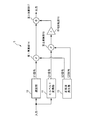
- FIG. 1 is a block diagram showing a schematic configuration of a vehicle alarm device according to the present embodiment.
- a vehicle alarm device (notification device) 1 includes a signal control unit (signal output determination unit) 2, a sweep signal generation unit 3, a sweep signal division unit 4, a first frequency conversion unit (frequency conversion unit) 5, A second frequency converter (frequency converter) 6, a first adder 7, a second adder 8, an output signal adjuster 9, four speakers EX 1, EX 2, EX 3, EX 4 (a plurality of exciters); have.
- the signal control unit 2 outputs a sweep signal generation signal to the sweep signal generation unit 3. Further, the signal control unit 2 outputs a speaker control signal for controlling (adjusting) at which timing of which speaker among the speakers EX1 to EX4 the vibration is generated, to the output signal adjusting unit 9. To do.
- the warning signal output unit 100 is a device that outputs a warning signal such as a lane departure signal, a vehicle approach signal, a dozing detection signal, or a sharp curve signal.
- the lane departure signal is an alarm signal output when the vehicle departs from the lane.
- the vehicle approach signal is an alarm signal that is output when an obstacle (such as a vehicle that is traveling forward or backward) approaches forward or backward.
- a doze detection signal is an alarm signal that is output when a driver's drowsiness is detected by detecting the driver's face angle, blinking interval, or by detecting fluctuations in the center position of the steering wheel. It is.
- the sharp curve signal is an alarm signal that is output when it is detected that there is a sharp curve ahead of the vehicle.
- These alarm targets are detected by a commonly used method such as a method of photographing a vehicle front image and analyzing the image, or a method of detecting a reflected wave by irradiating a radar wave forward. Done.
- the signal control unit 2 When the signal control unit 2 receives an alarm signal from the alarm signal output unit 100, the signal control unit 2 outputs a sweep signal generation signal to the sweep signal generation unit 3. In addition, when the signal control unit 2 receives an alarm signal from the alarm signal output unit 100, the signal control unit 2 instructs the output signal adjustment unit 9 to receive the type of the alarm signal (lane departure signal, vehicle approach signal, doze detection signal, A different speaker control signal is output according to any one of the sharp curve signals. What kind of speaker control signal is output according to the type of the received alarm signal will be described later.
- the speakers EX1 to EX4 notify the driver by outputting vibrations and sounds simultaneously to alert the driver.
- exciters are used as the speakers EX1 to EX4.
- An exciter is an acoustic output device capable of transmitting vibration and sound transmitted from a voice coil to an object in contact with the exciter and using the object as a diaphragm.
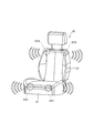
- FIG. 2 is a diagram schematically showing a state in which the speakers EX1 to EX4 are installed in the driver's seat (seat) 20 of the vehicle.
- the speaker EX ⁇ b> 1 is installed at the left front portion of the seat surface portion 21 of the driver seat 20.
- the speaker EX2 is installed in the right front portion of the seat surface portion 21 of the driver seat 20.
- the speaker EX3 is installed in the upper left part of the backrest 22 of the driver's seat 20.
- the speaker EX4 is installed in the upper right portion of the backrest 22 of the driver's seat 20.
- the speakers EX1 to EX4 are installed on a cushion material which is an interior member of the seat surface portion 21 and the backrest portion 22.
- the sweep signal generation unit 3 generates a sine wave sweep signal.
- the sweep signal means a signal obtained by changing the frequency of a predetermined wave continuously at a constant speed from the initial frequency to the target frequency.
- a sine wave is used as an example of the predetermined wave.
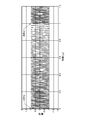
- the sweep signal generation unit 3 receives the sweep signal generation signal from the signal control unit 2, as shown in FIG. 3, the sweep signal has an initial frequency of 120 Hz, a target frequency of 40 Hz, and a sweep time of 1 second.
- a sweep signal in which a wave is swept is generated. Sweep is changing the frequency continuously at a constant speed.
- FIG. 3 shows a case where a sweep signal having one cycle of 1 second is repeatedly generated.
- the generated sweep signal is output to the sweep signal dividing unit 4.
- the initial frequency is 120 Hz and the target frequency is 40 Hz, but this frequency range is not particularly limited.
- the frequency range is not limited as long as it is within a frequency range in which the exciter can output a signal as vibration. It is desirable to use a frequency at which the driver can easily feel the vibration of the exciter if it is in a frequency range in which vibration can be output in the exciter.
- the predetermined wave used for the sweep signal is not necessarily limited to a sine wave. Other waveforms may be shown.
- the sweep signal dividing unit 4 divides the one-cycle sweep signal generated by the sweep signal generating unit 3 into a first half part and a second half part based on the frequency band.
- the frequency range in which the frequency of the sweep signal is changed (for example, a range of 120 Hz to 40 Hz as shown in FIG. 3) is partially overlapped.
- the sweep signal dividing unit 4 divides the sweep signal into a first-half sweep signal (high-frequency sweep signal) and a second-half sweep signal (low-frequency sweep signal).
- the high-frequency sweep signal is a signal in which the frequency of the sine wave is changed in a frequency band near the high frequency that includes the overlap frequency band and is equal to or higher than the frequency of the overlap frequency band.
- the low-frequency sweep signal is a signal in which the frequency of the sine wave is changed in a frequency band near the low frequency that includes the overlap frequency band and is equal to or lower than the frequency of the overlap frequency band.
- the sweep signal generation unit 3 generates a sweep signal with an initial frequency of 120 Hz and a target frequency of 40 Hz. For this reason, the sweep signal is generated by continuously changing the frequency of the sine wave at a constant speed from a high frequency to a low frequency. Therefore, when the frequency of the sine wave changes at a constant speed, the initial frequency becomes a high frequency value, and the frequency value changes to a low value as time passes. Therefore, the first half of the sweep signal is a sweep signal (high frequency sweep signal) having a frequency band closer to the high frequency than the second half of the sweep signal. In addition, the sweep signal in the latter half is a sweep signal (a low-frequency sweep signal) having a frequency band closer to the lower frequency than the sweep signal in the first half.
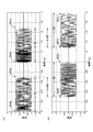
- FIG. 4 is a diagram showing a state where the sweep signal shown in FIG. 3 is divided.
- FIG. 4A shows a divided sweep signal (high-frequency sweep signal) in the first half.
- FIG. 4B shows the divided second half sweep signal (low-frequency sweep signal).
- the first half of the sweep signal (high frequency sweep signal) has an initial frequency of 120 Hz and a target frequency of 64 Hz.
- the second half of the sweep signal (low frequency sweep signal) has an initial frequency of 96 Hz and a target frequency of 40 Hz.
- the sweep time of the sweep signal in the first half is 0.7 seconds
- the sweep time of the sweep signal in the second half is also 0.7 seconds.
- the second half 0.4 seconds of the first half sweep signal and the first half 0.4 seconds of the second half sweep signal overlap.
- the divided sweep signals are shown for two periods (two seconds).
- fade-in processing processing in which the amplitude gradually increases
- fade-out processing processing in which the amplitude gradually decreases
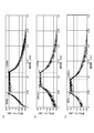
- FIG. 5 is a diagram showing the frequency characteristics of the sweep signal shown in FIGS. 3 and 4 (a) and 4 (b).
- FIG. 5A shows the frequency characteristics of the sweep signal before division shown in FIG.
- FIG. 5B shows frequency characteristics of the first half of the sweep signal (high frequency sweep signal) shown in FIG.
- FIG. 5C shows the frequency characteristics of the second half of the sweep signal (low frequency sweep signal) shown in FIG.
- the gain (signal level) in the sweep range of 40 Hz to 120 Hz shows a high value.
- the gain (signal level) in the sweep range of 64 Hz to 120 Hz shows a high value.
- the gain (signal level) in the sweep range of 40 Hz to 96 Hz shows a high value.
- the first half of the sweep signal (high frequency sweep signal) and the second half of the sweep signal (low frequency sweep signal) are over in the frequency band of 64 Hz to 96 Hz. It turns out that it is divided in a wrapped state.
- the range of 64 Hz to 96 Hz corresponds to the overlap frequency band.
- the overlap frequency band includes the frequency band of the first half of the sweep signal and the frequency band of the second half of the sweep signal.
- the frequency band of the first half of the sweep signal (high frequency sweep signal) shown in FIG. 5B is in the range of 64 Hz to 120 Hz.
- the frequency band of the first half of the sweep signal (high frequency sweep signal) includes the range of 64 Hz to 96 Hz which is the overlap frequency band as described above, and from the frequency band closer to the high frequency than the frequency of the overlap frequency band.
- the first half of the sweep signal (high-frequency sweep signal) is a signal that changes the frequency of the sine wave at a constant speed from a high frequency to a low frequency within a frequency band of 64 Hz to 120 Hz.
- the frequency band of the second half of the sweep signal includes a range of 64 Hz to 96 Hz which is an overlap frequency band, and is composed of a frequency band closer to the lower frequency than the frequency of the overlap frequency band.
- the second half of the sweep signal is a signal that changes the frequency of the sine wave at a constant speed from a high frequency to a low frequency within a frequency band of 40 Hz to 96 Hz.
- the first frequency conversion unit 5 and the second frequency conversion unit 6 generate a higher frequency signal than the sweep signal based on each of the sweep signals divided by the sweep signal division unit 4.
- the first frequency conversion unit 5 receives the divided first-half sweep signal (high-frequency sweep signal) and performs frequency conversion processing.
- the second frequency conversion unit 6 receives the divided second-half sweep signal (low-frequency sweep signal) and performs frequency conversion processing. Since the first frequency conversion unit 5 and the second frequency conversion unit 6 have the same internal configuration and the same processing contents, only the first frequency conversion unit 5 will be described in this embodiment for convenience.
- FIG. 6 is a block diagram showing a schematic configuration of the first frequency converter 5.
- the first frequency conversion unit 5 includes a Hilbert conversion unit 11, a delay unit 12, a sine wave generation unit 13, a first multiplication unit 14, a second multiplication unit 15, a phase inversion unit 16, and a third addition unit. 17.
- the sweep signal divided by the sweep signal dividing unit 4 is input to the Hilbert transform unit 11 and the delay unit 12.
- the divided sweep signal is referred to as a divided sweep signal.
- the divided sweep signal is a name that generically refers to both the first half of the sweep signal and the second half of the sweep signal.
- the Hilbert transform unit 11 generates a Q1 signal that is rotated by 90 degrees with respect to the input divided sweep signal.
- the Hilbert transform unit 11 according to the present embodiment is configured by an FIR (Finite Impulse Response) filter, and sets the filter length to 128 taps.
- the Q1 signal generated by the Hilbert transform unit 11 is output to the second multiplication unit 15.
- the delay unit 12 corrects a delay that occurs in association with the 90-degree phase rotation process in the Hilbert transform unit 11.
- the delay unit 12 generates an I1 signal having a 0-degree phase by performing delay correction on the input divided sweep signal.
- the I1 signal generated by the delay process in the delay unit 12 is output to the first multiplication unit 14.
- the sine wave generator 13 generates an I2 signal composed of a 0 degree phase sine wave and a Q2 signal composed of a 90 degree phase sine wave in accordance with the set conversion frequency.
- the 0 degree phase I2 signal generated by the sine wave generator 13 is output to the first multiplier 14.
- the 90-degree phase Q2 signal generated by the sine wave generator 13 is output to the second multiplier 15.
- the first multiplication unit 14 multiplies the 0 degree phase I1 signal input from the delay unit 12 and the 0 degree phase I2 signal input from the sine wave generation unit 13.
- the signal obtained by performing the multiplication process of the 0 degree phase I1 signal and the 0 degree phase I2 signal in the first multiplier 14 is output to the third adder 17.
- the second multiplying unit 15 multiplies the 90 degree phase rotated Q1 signal input from the Hilbert transforming unit 11 and the 90 degree phase Q2 signal input from the sine wave generating unit 13.
- the signal obtained by multiplying the 90-degree phase Q1 signal and the 90-degree phase Q2 signal in the second multiplication section 15 is output to the phase inversion section 16.
- the phase inversion unit 16 inverts the phase of the input signal.
- the phase inverter 16 inverts the phase of the input signal and then outputs the signal to the third adder 17.
- the third adder 17 receives a signal input from the first multiplier 14 (a signal obtained by multiplying the 0 degree phase I1 signal and the 0 degree phase I2 signal) and the second multiplier 15. (The signal that has undergone phase inversion after the multiplication process of the Q1 signal of 90 degrees and the Q2 signal of 90 degrees) is added. In this way, the signal added by the third adder 17 becomes a signal in which the mirror image is suppressed and a signal obtained by frequency-shifting (frequency converting) the sweep signal to the middle band side.
- FIG. 7A shows frequency characteristics of a signal (high-frequency sound signal) obtained by performing frequency conversion processing on the first half of the sweep signal (high-frequency sweep signal) in the first frequency conversion unit 5.
- FIG. 7B shows the frequency characteristics of a signal (low-frequency sound signal) obtained by performing frequency conversion processing on the second half of the sweep signal (low-frequency sweep signal) in the second frequency converter 6. ing.
- the frequency of the sine wave generated in the sine wave generator 13 is 800 Hz.
- the first half of the sweep signal (frequency range of 64 Hz to 120 Hz) is multiplied by an 800 Hz sine wave.
- the signal (high frequency sound signal) obtained by performing the frequency conversion process on the first half of the sweep signal (high frequency sweep signal) has an initial frequency of 920 Hz (120 Hz + 800 Hz) and a target frequency of 864 Hz (64 Hz + 800 Hz).
- a signal (low frequency sound signal) obtained by performing frequency conversion processing on the second half sweep signal (low frequency sweep signal) has an initial frequency of 896 Hz (96 Hz + 800 Hz) and a target frequency of 840 Hz (40 Hz + 800 Hz).
- the frequency band of the frequency-converted signal is not limited to the above-described range of 840 Hz to 920 Hz.
- the frequency band of the signal subjected to the frequency conversion process is not particularly limited as long as it is a frequency band in which the signals subjected to the frequency conversion process are output as sound in the speakers (exciters) EX1 to EX4.
- the first half of the sweep signal that has been frequency-converted (frequency shifted) by the first frequency converter 5 to the frequency band closer to the mid-range (864 Hz to 920 Hz) is the first half of the sound signal (high-frequency sound signal). It is output to the adder 7.
- the second half of the sweep signal which is frequency-converted (frequency shifted) by the second frequency converter 6 to the frequency band closer to the mid-range (840 Hz to 896 Hz), is the latter half of the sound signal (low-frequency sound signal). ) Is output to the second adder 8.
- the first addition unit 7 includes the first half of the sound signal (high frequency sound signal) input from the first frequency conversion unit 5 and the first half of the sweep signal (high frequency sweep signal) input from the sweep signal dividing unit 4. Addition processing is performed.
- the first half of the sound signal (high frequency sound signal) and the first half of the sweep signal (high frequency sweep signal) subjected to the addition processing in the first addition unit 7 are the first half of the notification signal V1 (first notification signal). It is output to the output signal adjustment unit 9.
- the second adder 8 also includes the second half of the sound signal (low frequency sound signal) input from the second frequency converter 6 and the second half of the sweep signal (low frequency sweep) input from the sweep signal divider 4. Signal).
- the latter half of the sound signal (low frequency sound signal) and the latter half of the sweep signal (low frequency sweep signal) subjected to the addition processing in the second adder 8 are the latter half of the notification signal V2 (second notification signal). It is output to the output signal adjustment unit 9.
- the output signal adjustment unit 9 includes a first half notification signal V1 (first notification signal) input from the first addition unit 7 and a second half notification signal V2 (second notification signal) input from the second addition unit 8. ) Is controlled (adjusted) to which speaker of the speakers EX1 to EX4 is output at which timing based on the speaker control signal received from the signal control unit 2.
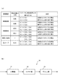
- FIG. 8A shows a combination of the type of the speaker control signal (alarm type) received from the signal control unit 2, the direction of the alarm target with respect to the vehicle (the direction of the alarm target), the speaker that performs the output, and the notification signal. It is the table
- the signal control unit 2 determines from the warning signal whether the deviated lane is on the right side or the left side. . For example, when the deviating lane is the left lane, the signal control unit 2 outputs “notification regarding lane departure” and “information indicating departure from the left lane” as a speaker control signal. The signal is output to the signal adjustment unit 9. Based on the speaker control signal received from the signal control unit 2, the output signal adjustment unit 9 determines that it is “notification about lane departure” and also determines that it is “left lane departure”. When the output signal adjustment unit 9 determines that the deviating lane is on the left side, the output signal adjustment unit 9 first notifies the speaker EX1 (exciter) installed in the left front portion of the seat surface portion 21 of the first half portion. Is output.
- EX1 exciter
- the output of the notification signal V1 in the first half When the output of the notification signal V1 in the first half is started, vibration of 120 Hz and sound of 920 Hz are output from the speaker EX1. Thereafter, the frequency of vibration and sound of the notification signal V1 output from the speaker EX1 gradually decreases at a constant speed (changes at a constant speed from a high frequency to a low frequency). Then, at the timing when the notification signal V1 in the first half is output as vibration of 96 Hz and sound of 896 Hz, the output signal adjustment unit 9 is in the second half with respect to the speaker EX3 (exciter) installed on the upper left side of the backrest portion 22. The partial notification signal V2 is output. When the output of the second half notification signal V2 is started, a vibration of 96 Hz and a sound of 896 Hz are output from the speaker EX3.
- the timing at which the notification signal V1 is output as vibration of 96 Hz refers to the frequency of a sine wave that changes at a constant speed from a higher frequency to a lower frequency in the frequency band of the first half of the sweep signal in the notification signal V1. , Meaning the timing to reach a frequency within the overlap frequency band (96 Hz which is a high frequency in the range of 64 Hz to 96 Hz).
- the vibration and sound frequencies of the notification signal V1 output from the speaker EX1 and the vibration and sound frequencies of the notification signal V2 output from the speaker EX3 gradually decrease. That is, it changes at a constant speed from a high frequency to a low frequency.
- the notification signal V1 is output from the speaker EX1 and the notification signal V2 is notified from the speaker EX3, the notification signal V1 of the first half and the notification signal V2 of the second half overlap, The state is output from the speakers EX1 and EX3.
- the output signal adjustment unit 9 is output from the speaker EX1 installed in the left front portion of the seat surface portion 21.
- the process of outputting the notification signal V1 is finished, and the process of continuously outputting the vibration and sound of the notification signal V2 in the latter half portion is performed only from the speaker EX3 (exciter) installed on the upper left side of the backrest portion 22.
- the timing at which the first half notification signal V1 is output as a vibration of 64 Hz is a sine that changes at a constant speed from a higher frequency to a lower frequency in the frequency band of the first half sweep signal in the notification signal V1. This means the timing at which the wave frequency deviates from the frequency within the overlap frequency band (64 Hz, which is a lower frequency in the range of 64 Hz to 96 Hz).
- the output signal adjustment unit 9 outputs the notification signal V2 from the speaker EX3 installed on the upper left side of the backrest 22 after the notification signal V2 output from the speaker EX3 is output as 40 Hz vibration and 840 Hz sound.
- the notification process described above describes the case where the notification signal V1 in the first half and the notification signal V2 in the second half are performed for one cycle (1 second) of the sweep signal before division.
- the notification process described above is repeatedly executed while the speaker control signal is transmitted from the signal control unit 2.
- the driver is notified using vibration and sound so that the time difference between the notification signal V1 in the first half and the notification signal V2 in the second half is generated. For this reason, it becomes possible for the driver to experience directional vibration / sound by the time difference between the timing at which vibration and sound are output from the speaker EX1 and the timing at which vibration and sound are output from the speaker EX3. . In addition, it is possible to make the driver recognize the difference in the notification content (alarm content) due to directional vibration or the like.
- the notification process is performed in a state where the vibration and sound in the second half of the notification signal V1 output from the speaker EX1 and the vibration and sound in the first half of the notification signal V2 output from the speaker EX3 are overlapped.
- the driver first feels vibration / sound only with the front speaker EX1, and then feels vibration / sound integrally with both the front speaker EX1 and the upper speaker EX3. Vibration and sound can be experienced only by the speaker EX3.
- By causing the driver to feel such vibrations and sounds using the overlap it is possible to further notify the driver with directionality.
- the vibration / sound output from the speakers EX1 and EX3 is configured to notify the driver by gradually changing the frequency. For this reason, even if it is a case where any one vibration and sound of speaker EX1 or EX3 are made to experience, the driver
- the vibration is not only generated by the frequency band of the sweep signal in the notification signal. With the frequency band closer to the middle range of the sound signal, it is possible to output the sound so as to be superimposed on the vibration. For this reason, not only can the driver experience the notification as vibration, but the notification can be recognized by hearing as sound, and the notification can be performed more effectively.
- the signal control unit 2 When the signal control unit 2 receives a warning signal indicating that the vehicle has deviated from the warning signal output unit 100 and the deviating lane is on the right side, the signal control unit 2 outputs the output signal adjustment unit 9. On the other hand, “notification about lane departure” and “information indicating departure from right lane” is output as a speaker control signal. Based on the speaker control signal received from the signal control unit 2, the output signal adjustment unit 9 outputs the vibration and sound of the notification signal V ⁇ b> 1 to the speaker EX ⁇ b> 2 (exciter) installed in the right front portion of the seat surface unit 21. Perform the process. Thereafter, the output signal adjustment unit 9 performs a process of outputting the vibration and sound of the notification signal V2 to the speaker EX4 (exciter) installed on the upper right side of the backrest unit 22.
- the signal control unit 2 controls the output signal adjustment unit 9.
- “Notification of approaching vehicle” and “information indicating that the vehicle is ahead” is output as a speaker control signal.
- the output signal adjustment unit 9 Based on the speaker control signal received from the signal control unit 2, the output signal adjustment unit 9 outputs the vibration and sound of the notification signal V ⁇ b> 1 to the speakers EX ⁇ b> 1 and EX ⁇ b> 2 installed at the left and right front portions of the seat surface unit 21. Process. Thereafter, the output signal adjustment unit 9 performs a process of outputting vibration and sound of the notification signal V2 to the speakers EX3 and EX4 installed on the left and right upper portions of the backrest unit 22.
- the signal control unit 2 controls the output signal adjustment unit 9.
- “notification of approaching vehicle” and “information indicating that the vehicle is behind” is output as a speaker control signal.
- the output signal adjustment unit 9 based on the speaker control signal received from the signal control unit 2, a process for outputting vibration and sound of the notification signal V ⁇ b> 1 to the speakers EX ⁇ b> 3 and EX ⁇ b> 4 installed on the left and right upper portions of the backrest unit 22 I do.
- the output signal adjustment unit 9 performs a process of outputting vibration and sound of the notification signal V2 to the speakers EX1 and EX2 installed in the left and right front portions of the seat surface portion 21.
- the signal control unit 2 receives an alarm signal related to the detection of the driver's nap from the alarm signal output unit 100, the signal control unit 2 notifies the output signal adjustment unit 9 by “notification for detection of dozing”. Information indicating that it is present is output as a speaker control signal. Based on the speaker control signal received from the signal control unit 2, the output signal adjustment unit 9 performs a process of outputting the vibration and sound of the notification signal V1 at the same timing for all the speakers EX1 to EX4.
- the signal control unit 2 receives an alarm signal related to steep curve detection from the alarm signal output unit 100, the signal control unit 2 is “notification for steep curve detection” to the output signal adjustment unit 9. Information to that effect is output as a speaker control signal.
- the output signal adjustment unit 9 Based on the speaker control signal received from the signal control unit 2, the output signal adjustment unit 9 outputs the vibration and sound of the notification signal V ⁇ b> 1 to the speakers EX ⁇ b> 1 and EX ⁇ b> 2 installed at the left and right front portions of the seat surface unit 21. Process. Thereafter, the output signal adjustment unit 9 performs a process of outputting vibration and sound of the notification signal V2 to the speakers EX3 and EX4 installed on the left and right upper portions of the backrest unit 22.
- the driver can sensuously determine what alarm has been notified according to the position of the speaker where vibration and sound are output and the combination thereof, and pay attention. It is possible to determine the direction to be.
- the exciter is installed on the cushioning material of the seat surface portion 21 and the backrest portion 22 to vibrate from a plurality of positions (locations) by resonance. Can be reduced.
- the speakers (exciters) EX1 to EX4 provided on the seat surface portion 21 and the backrest portion 22 perform time division and frequency division for lane departure notification, vehicle approach notification, doze notification, sharp curve notification, and the like.
- the swept signal can be output as vibration. Moreover, it can be made to output as a sound by the midrange sound signal by which the frequency conversion process was carried out. For this reason, it is possible to effectively notify the driver. Furthermore, it becomes possible to notify information with directionality, and it becomes possible to improve the recognition of warnings to the driver.
- the frequency band of the sweep signal to be output as vibration is frequency-converted to the middle frequency band, so that the speakers (exciters) EX1 to EX4 are caused by vibration.
- sound output can be performed as a notification.
- a vibration output device vibration generator
- a sound output device sound reproduction speaker
- the alarm device and the alarm method according to the present invention have been described in detail by using the vehicle alarm device 1 shown in the embodiment as an example.
- the notification device and the notification method according to the present invention are not limited to the examples shown in the embodiments. It is obvious for those skilled in the art that various changes or modifications can be conceived within the scope of the claims, and these are also the same as the vehicle alarm device 1 shown in the embodiment. It is possible to achieve the same effect.
- the notification signal V1 in the first half and the notification signal V2 in the second half are overlapped and output. Since this notification signal output is configured to output not only vibration but also sound, the output of the sound in the first half and the second half overlaps at the time of overlap, thereby doubling the sound gain. Is output. For this reason, at the time of overlap, it is also possible to adopt a configuration that reduces the magnitude (gain) of the notification sound by sound. Thus, by adjusting the gain of the sound at the time of overlap, it is possible to prevent the notification sound from becoming excessively loud. In addition, it is possible to cause the driver to intuitively recognize the directional notification process from the output of the first half of the sound to the output of the second half of the sound in a state in which no sense of incongruity is audibly generated.
- the target frequency in the sweep signal is set to a frequency value higher than the initial frequency, and the frequency of the sine wave is changed from a high frequency to a low frequency at a constant speed (sweep is performed).
- changing the frequency is not limited to changing (sweeping) from a high frequency to a low frequency, and may be a change from a low frequency to a high frequency.
- the direction of the change in the frequency may be any as long as it can provide the driver with a transition feeling due to the change in the frequency.
- the first frequency conversion unit 5 or the second frequency conversion unit 6 multiplies the sweep signal by the 800 Hz sine wave to The sound signal was generated.
- human hearing has logarithmic characteristics, it becomes difficult to sense a sufficient frequency transition (frequency change of the sound signal) when the frequency increases.
- the frequency band for changing the frequency in the sound signal is narrow, there is a tendency that it is difficult to feel a sufficient frequency transition.
- FIG. 8B is a block diagram showing an example of a frequency expansion unit (frequency conversion unit) 30 used in the vehicle alarm device 1 instead of the first frequency conversion unit 5 and the second frequency conversion unit 6. .
- the frequency extension unit 30 extends the frequency and bandwidth of the sweep signal.
- the frequency extension unit 30 includes a squaring unit 31, an HPF (High-pass filter) unit 32, and a gain unit 33.
- the squaring unit 31 squares the first half of the sweep signal (high-frequency sweep signal) or the second half of the sweep signal (low-frequency sweep signal) input from the sweep signal dividing unit 4.
- the sweep signal squared in the squaring unit 31 is doubled in frequency and bandwidth, and converted into a sound signal (a high-frequency sound signal or a low-frequency sound signal) that can be heard as a sound.
- the HPF unit 32 removes the signal output near the DC component (DC component) (near 0 Hz) of the sound signal square-processed by the squaring unit 31.
- the HPF unit 32 removes (reduces) the signal output in the vicinity of the DC component by performing high-pass filter processing on the squared sound signal.
- the gain unit 33 doubles the amplitude of the signal with respect to the sound signal from which the signal output near the DC component has been removed. By performing the process of doubling the amplitude by the gain unit 33, the amplitude of the sound signal can be adjusted so as to have the same amplitude as that of the sweep signal input to the frequency extension unit 30.
- the above-described squaring unit 31, HPF unit 32, and gain unit 33 can be cascade-connected in plural sets as necessary. By cascade-connecting the set of the squaring unit 31, the HPF unit 32, and the gain unit 33, the frequency and bandwidth of the sound signal can be expanded to 2 times, 4 times, 8 times, 16 times, and so on.
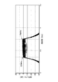
- the second half of the sweep signal (low-frequency sweep signal) shown in FIG. 5C inputs the second half of the sweep signal (low-frequency sweep signal) shown in FIG. 5C to the frequency extension unit 30, and in the frequency extension unit 30, the square unit 31, the HPF unit 32, and The frequency characteristics of a sound signal in which the frequency and the bandwidth are expanded by 8 times by cascading three gain units 33 are shown.
- the second half of the sweep signal (low-frequency sweep signal) shown in FIG. 5C has an initial frequency of 96 Hz and a target frequency of 40 Hz. For this reason, in the frequency characteristics of the signal shown in FIG. 9, the frequency and the bandwidth are expanded by a factor of 8, resulting in a sound signal having an initial frequency of 768H and a target frequency of 320 Hz.
- the sound signal generated in this way is added to the original sweep signal by the first adder 7 and the second adder 8 and output from the speakers EX1 to EX4, thereby generating a low-frequency vibration.
- a sound signal (low-frequency sound signal) that generates a sound whose frequency and bandwidth are expanded by 8 times can be output to the driver.
- the frequency extension unit 30 can increase the amplitude of the mid-range sound signal by eight times compared to the first frequency conversion unit 5 and the second frequency conversion unit 6 shown in FIG. For this reason, it becomes easy for the driver to feel the transition (change) of the frequency of the output sound, and the recognition of the notification signal to the driver can be improved.
- the first frequency conversion unit 5 and the second frequency conversion unit 6 can It is also possible to improve the recognition of the notification signal to the driver by expanding the bandwidth of the sound signal frequency-converted into a region several times.
- the bandwidth of the sound signal shown in FIGS. 7A and 7B is a bandwidth of 80 Hz from 920 Hz to 840 Hz.
- the bandwidth may be expanded so that the bandwidth becomes a bandwidth of 160 Hz or a bandwidth of 320 Hz.
- the frequency band of the sound signal expanded in the frequency expansion unit 30, the frequency band of the sound signal converted in the first frequency conversion unit 5 and the second frequency conversion unit 6, or the bandwidth of the converted sound signal is a frequency band that is different from driving noise (a distinct frequency band in the middle frequency range) so that the notification sound (output of the sound signal) is not masked by the driving noise of the vehicle (it is not difficult to hear). It is desirable to do.
- the frequency expansion unit 30 and the frequency conversion units 5 and 6 may be combined.
- the frequency extension unit 30 and the frequency conversion units 5 and 6 after extending the frequency band by the frequency extension unit 30, the frequency conversion units 5 and 6 can be shifted to an arbitrary mid-range frequency that is not masked by the running sound. It becomes possible to convert the frequency.
- Phase inversion unit 17 (of the first frequency conversion unit or second frequency conversion unit) ... (of the first frequency conversion unit or second frequency conversion unit) 3rd addition part 20 ... driver's seat (seat) 21 ... Seat surface part (of the driver's seat) 22 ... Backrest part (of the driver's seat) 30 ... Frequency extension part (frequency conversion part) 31 ... Square section 32 (of the frequency extension section) ... HPF section 33 (of the frequency extension section) ... Gain section 100 (of the frequency extension section) ... Alarm signal output sections EX1 to EX4 ... Speakers (exciters)
Abstract
A notification device (1) is provided with: a sweep signal generation unit (3) that generates a sweep signal, of which the frequency of a predetermined wave is varied at a fixed speed within a frequency band at which a vibration can be generated by exciters (EX1, EX2, EX3, EX4); a sweep signal dividing unit (4) that divides the sweep signal into a high-range sweep signal near a high range including an overlap frequency band, and a low-range sweep signal near a low range; a signal output determination unit (2) that determines an exciter from which to output a signal; and an output signal adjustment unit (9) that carries out adjustment to output the high-range sweep signal and the low-range sweep signal from the exciter that was determined.
Description
本発明は報知装置および報知方法に関し、より詳細には、ユーザに対して振動により報知を行うことが可能な報知装置および報知方法に関する。
The present invention relates to a notification device and a notification method, and more particularly to a notification device and a notification method that can notify a user by vibration.
従来より、走行車両が車線を逸脱した場合に、運転席を振動させることによって、運転者に注意を与える(報知する)車両用警報装置が提案されている(特許文献1、段落[0029]、第1図、第2図参照)。この車両用警報装置では、シートの座面の右側と左側とに振動体が設けられている。車両が右側の車線を超えた場合には、右側の振動体を振動させ、車両が左側の車線を超えた場合には、左側の振動体を振動させる構造になっている。
Conventionally, a vehicle alarm device has been proposed that alerts (notifies) a driver by vibrating a driver's seat when a traveling vehicle deviates from the lane (Patent Document 1, paragraph [0029], FIG. 1 and FIG. 2). In this vehicle alarm device, vibrating bodies are provided on the right side and the left side of the seat surface of the seat. When the vehicle exceeds the right lane, the right vibrating body is vibrated, and when the vehicle exceeds the left lane, the left vibrating body is vibrated.
また、シートフレームに複数の振動素子を設けて、振動素子による振動の発生位置を少しずつずらして振動に進行性を与える(振動波を発生させる)ことによって、方向性のある情報を運転者に報知する車両用警報装置が提案されている(特許文献2、段落[0064]~[0067]、第5図、第6図参照)。
In addition, by providing a plurality of vibration elements on the seat frame and shifting the vibration generation position by the vibration elements little by little to give the vibration advancing (generating vibration waves), it is possible to provide directional information to the driver. There has been proposed a vehicle warning device for notification (see Patent Document 2, paragraphs [0064] to [0067], FIGS. 5 and 6).
これらの車両用警報装置により、運転者は車両の状況に応じて発せられる注意(報知、警告)を振動によって体感することが可能となる。
These vehicle alarm devices allow the driver to experience the attention (notification, warning) that is issued according to the vehicle situation by vibration.
しかしながら、振動によって運転者に対して注意を与える方法では、座席内のフレーム構造や振動体(振動素子)の設置位置等によって、運転者が感じ取る振動に差が生じる。このため、十分な報知を行うことができない場合が生じ得る。例えば、特許文献1に示される車両用警報装置では、太ももから臀部および腰部にかけて振動を与える構造となっている。しかしながら、左右の単調な振動の違いを、臀部および腰部で明確に判断することは、必ずしも容易ではない。
However, in the method of giving attention to the driver by vibration, there is a difference in vibration felt by the driver depending on the frame structure in the seat and the installation position of the vibrating body (vibrating element). For this reason, the case where sufficient alerting | reporting cannot be performed may arise. For example, the vehicle alarm device disclosed in Patent Document 1 has a structure in which vibration is applied from the thigh to the buttocks and the waist. However, it is not always easy to clearly determine the difference between the left and right monotonous vibrations in the buttocks and the waist.
また、特許文献2に示される車両用警報装置では、シートフレームに振動素子が設けられている。このため、振動素子の振動によってフレームに共振が発生する傾向があり、振動素子の設置位置(振動位置)以外でも振動が発生してしまうおそれがある。したがって、結果的にシートの複数位置で振動が発生してしまうことになり、振動の発生位置を少しずつずらしても、運転者が方向性のある情報を振動によって識別することが困難であるという問題があった。
Further, in the vehicle alarm device disclosed in Patent Document 2, a vibration element is provided in the seat frame. For this reason, there is a tendency that resonance occurs in the frame due to the vibration of the vibration element, and there is a possibility that vibration is generated at a position other than the installation position (vibration position) of the vibration element. As a result, vibration is generated at a plurality of positions on the seat, and it is difficult for the driver to identify directional information by vibration even if the vibration generation position is shifted little by little. There was a problem.
本発明は、上記課題に鑑みてなされたものであり、運転者が方向性のある情報を十分に認知することが可能な報知装置および報知方法を提供することを課題とする。
This invention is made | formed in view of the said subject, and makes it a subject to provide the alerting | reporting apparatus and the alerting | reporting method in which a driver | operator can fully recognize direction information.
本発明の一態様として報知装置は、座席のクッション材部分であって当該座席の異なる位置に設置される複数のエキサイタと、該エキサイタで信号を振動として出力させることが可能な周波数帯域内において、一定の速度で所定波の周波数を変化させることにより、前記振動の周波数を連続的に変化させることが可能なスイープ信号を生成するスイープ信号生成部と、前記スイープ信号において一定の速度で変化される周波数帯域内の一部の帯域をオーバーラップ周波数帯域とし、該オーバーラップ周波数帯域を含み当該オーバーラップ周波数帯域の周波数以上となる高域寄りの周波数帯域内で前記所定波の周波数を変化させることにより、前記振動の周波数を連続的に変化させる高域スイープ信号と、前記オーバーラップ周波数帯域を含み当該オーバーラップ周波数帯域の周波数以下となる低域寄りの周波数帯域内で前記所定波の周波数を変化させることにより、前記振動の周波数を連続的に変化させる低域スイープ信号とに、前記スイープ信号を分割するスイープ信号分割部と、前記高域スイープ信号および前記低域スイープ信号のうち少なくとも一方の信号を、複数の前記エキサイタのうちのいずれか一のエキサイタより出力させ、前記高域スイープ信号および前記低域スイープ信号のうち少なくとも他方の信号を、複数の前記エキサイタのうちのいずれか他のエキサイタより出力させることを決定する信号出力決定部と、該信号出力決定部の前記決定に基づいて、前記高域スイープ信号および前記低域スイープ信号を、決定された前記いずれかのエキサイタより出力させるための調整を行う出力信号調整部とを備えることを特徴とする。
As one aspect of the present invention, the notification device is a cushion material portion of a seat and a plurality of exciters installed at different positions of the seat, and in a frequency band in which signals can be output as vibrations by the exciter, A sweep signal generator that generates a sweep signal capable of continuously changing the frequency of the vibration by changing the frequency of a predetermined wave at a constant speed, and the sweep signal is changed at a constant speed. By changing the frequency of the predetermined wave within a frequency band close to a high frequency band that includes the overlap frequency band and is equal to or higher than the frequency of the overlap frequency band, by setting a part of the frequency band as an overlap frequency band Including a high-frequency sweep signal that continuously changes the frequency of the vibration and the overlap frequency band. By changing the frequency of the predetermined wave within a low frequency band that is equal to or lower than the frequency of the overlap frequency band, the sweep signal is changed to a low frequency sweep signal that continuously changes the frequency of the vibration. A sweep signal dividing unit that divides, and at least one of the high-frequency sweep signal and the low-frequency sweep signal is output from any one of the exciters, and the high-frequency sweep signal and the high-frequency sweep signal Based on the determination of the signal output determination unit, a signal output determination unit that determines that at least the other signal of the low-frequency sweep signal is output from any other exciter of the plurality of exciters, The high frequency sweep signal and the low frequency sweep signal are output from one of the determined exciters. And an outputting signal adjusting unit for adjusting for.
また、本発明の他の態様として報知装置の報知方法は、座席のクッション材部分であって異なる位置に設置される複数のエキサイタで信号を振動として出力させることが可能な周波数帯域内において、一定の速度で所定波の周波数を変化させることにより、スイープ信号生成部が、前記振動の周波数を連続的に変化させることが可能なスイープ信号を生成するスイープ信号生成ステップと、前記スイープ信号において一定の速度で変化される周波数帯域内の一部の帯域をオーバーラップ周波数帯域とし、スイープ信号分割部が、該オーバーラップ周波数帯域を含み当該オーバーラップ周波数帯域の周波数以上となる高域寄りの周波数帯域内で前記所定波の周波数を変化させることにより、前記振動の周波数を連続的に変化させる高域スイープ信号と、前記オーバーラップ周波数帯域を含み当該オーバーラップ周波数帯域の周波数以下となる低域寄りの周波数帯域内で前記所定波の周波数を変化させることにより、前記振動の周波数を連続的に変化させる低域スイープ信号とに、前記スイープ信号を分割するスイープ信号分割ステップと、信号出力決定部が、前記高域スイープ信号および前記低域スイープ信号のうち少なくとも一方の信号を、複数の前記エキサイタのうちのいずれか一のエキサイタより出力させ、前記高域スイープ信号および前記低域スイープ信号のうち少なくとも他方の信号を、複数の前記エキサイタのうちのいずれか他のエキサイタより出力させることを決定する信号出力決定ステップと、該信号出力決定ステップによる前記決定に基づいて、出力信号調整部が、前記高域スイープ信号および前記低域スイープ信号を、決定された前記いずれかのエキサイタより出力させるための調整を行う出力信号調整ステップとを備えることを特徴とする。
Further, as another aspect of the present invention, the notification method of the notification device is a constant within a frequency band in which signals can be output as vibrations by a plurality of exciters installed at different positions on the cushion material portion of the seat. By changing the frequency of the predetermined wave at a speed of, the sweep signal generation unit generates a sweep signal capable of continuously changing the frequency of the vibration, and a constant in the sweep signal A part of the frequency band that varies depending on the speed is defined as the overlap frequency band, and the sweep signal division unit includes a frequency band closer to the high frequency band that includes the overlap frequency band and is equal to or higher than the frequency of the overlap frequency band. By changing the frequency of the predetermined wave with a high frequency sweep, the frequency of the vibration is continuously changed. The frequency of the vibration is continuously changed by changing the frequency of the predetermined wave in a frequency band close to a low frequency including a signal and the frequency of the overlap frequency band that is equal to or lower than the frequency of the overlap frequency band. A sweep signal dividing step for dividing the sweep signal into a region sweep signal, and a signal output determining unit, wherein at least one of the high region sweep signal and the low region sweep signal is converted into a plurality of the exciters. A signal output determination is made to output from any one of the exciters and to determine that at least the other of the high-frequency sweep signal and the low-frequency sweep signal is output from any other exciter of the plurality of exciters. And an output signal adjustment unit based on the determination by the signal output determination step , The high frequency sweep signal and the low-frequency sweep signal, characterized in that an output signal adjustment step of adjusting for outputting from the determined said one of the exciter.
上述の報知装置および報知方法において、エキサイタより出力される高域スイープ信号および低域スイープ信号は、エキサイタで信号を振動として出力させることが可能な周波数帯域内において、一定の速度で所定波(例えば、正弦波等)の周波数が変化される信号であるため、振動の周波数を連続的に変化させることが可能である。このため、座席に設置された異なるエキサイタより高域スイープ信号および低域スイープ信号を出力させることにより、周波数が徐々に変化する振動を座席の異なる位置でユーザに体感させることができる。さらに、高域スイープ信号が出力されるエキサイタの振動と、低域スイープ信号が出力されるエキサイタの振動との発生位置や発生タイミングを、信号出力決定部あるいは出力信号調整部で決定・調整する。この決定・調整により、方向性のある報知を行うことが可能となる。
In the notification device and the notification method described above, the high-frequency sweep signal and the low-frequency sweep signal output from the exciter are predetermined waves (for example, within a frequency band in which the exciter can output signals as vibrations). Therefore, the frequency of vibration can be continuously changed. For this reason, by outputting the high-frequency sweep signal and the low-frequency sweep signal from different exciters installed in the seat, it is possible to allow the user to experience vibrations with gradually changing frequencies at different positions of the seat. Furthermore, the signal output determination unit or the output signal adjustment unit determines and adjusts the generation position and generation timing of the vibration of the exciter that outputs the high-frequency sweep signal and the vibration of the exciter that outputs the low-frequency sweep signal. This determination / adjustment makes it possible to perform directional notification.
特に、上述の報知装置および報知方法では、エキサイタが座席のクッション材部分に設置されるため、エキサイタの振動により座席のフレーム等が共振してしまうことを防止することができる。さらに、振動位置の違いをより確実にユーザに体感させることが可能となる。
In particular, in the notification device and the notification method described above, since the exciter is installed in the cushion material portion of the seat, it is possible to prevent the frame of the seat from resonating due to the vibration of the exciter. Furthermore, it is possible to make the user feel the difference in vibration position more reliably.
また、高域スイープ信号および低域スイープ信号による振動は、振動の周波数が連続的に変化することを特徴としている。この特徴により、高域スイープ信号または低域スイープ信号のいずれかの信号が、いずれか1つのエキサイタで振動する場合であっても、複数のエキサイタで同時に振動する場合であっても、振動の変化を周波数の変化により感じ取ることが可能である。この周波数の変化に伴う振動の変化によって、単調な振動とは異なる、変化に富んだ振動を用いて報知を行うことが可能となる。
Also, the vibration caused by the high-frequency sweep signal and the low-frequency sweep signal is characterized in that the frequency of the vibration changes continuously. Due to this feature, even if either the high-frequency sweep signal or the low-frequency sweep signal is vibrated by any one exciter or is simultaneously vibrated by a plurality of exciters, the vibration change Can be sensed by a change in frequency. Due to the change in vibration accompanying the change in frequency, it is possible to perform notification using vibrations rich in change that are different from monotonous vibrations.
さらに、高域スイープ信号と低域スイープ信号とが異なるエキサイタで出力される場合には、一定の速度で変化する周波数の周波数帯域が高域スイープ信号と低域スイープ信号とで異なるため、より一層、ユーザは振動の変化を感じ取ることが可能になる。さらに、高域スイープ信号と低域スイープ信号とは、オーバーラップ周波数帯域において変化させることが可能な周波数帯域が一致するため、オーバーラップ周波数帯域における振動をより一層強調させて、ユーザに報知を体感させることが可能となる。
Furthermore, when the high frequency sweep signal and the low frequency sweep signal are output by different exciters, the frequency band of the frequency changing at a constant speed is different between the high frequency sweep signal and the low frequency sweep signal. The user can feel the vibration change. Furthermore, since the high frequency sweep signal and the low frequency sweep signal have the same frequency band that can be changed in the overlap frequency band, the vibration in the overlap frequency band is further emphasized, and the user can be notified. It becomes possible to make it.
また、上述した報知装置において、前記出力信号調整部は、前記信号出力決定部の前記決定に基づいて、前記高域スイープ信号を複数の前記エキサイタのうちのいずれか一のエキサイタより出力させ、前記低域スイープ信号を複数の前記エキサイタのうちのいずれか他のエキサイタより出力させる場合に、前記高域スイープ信号による出力を前記一のエキサイタにおいて開始させた後に、前記高域スイープ信号において高い周波数から低い周波数に向けて一定の速度で変化する前記所定波の周波数が、前記オーバーラップ周波数帯域内の周波数に到達するタイミングで、前記低域スイープ信号による出力を前記他のエキサイタにおいて開始させ、前記高域スイープ信号において高い周波数から低い周波数に向けて一定の速度で変化する前記所定波の周波数が、前記オーバーラップ周波数帯域内の周波数から脱するタイミングで、前記高域スイープ信号による出力を前記一のエキサイタにおいて終了させるものであってもよい。
Further, in the above-described notification device, the output signal adjustment unit outputs the high-frequency sweep signal from any one of the plurality of exciters based on the determination of the signal output determination unit, and When outputting a low-frequency sweep signal from any one of the plurality of exciters, the high-frequency sweep signal is started from the high frequency in the high-frequency sweep signal after starting output by the one exciter. At the timing when the frequency of the predetermined wave that changes at a constant speed toward a low frequency reaches a frequency within the overlap frequency band, output by the low-frequency sweep signal is started in the other exciter, and the high frequency In the sweep signal, it changes at a constant speed from a high frequency to a low frequency. Frequency of Teinami is at the timing to escape from the frequency of said overlapping frequency band, the output from the high frequency sweep signal may be one which terminates at the one exciter.
さらに、上述した報知装置の報知方法において、前記出力信号調整ステップにおいて、前記信号出力決定ステップによる前記決定に基づいて、前記高域スイープ信号を複数の前記エキサイタのうちいずれか一のエキサイタより出力させ、前記低域スイープ信号を複数の前記エキサイタのうちいずれか他のエキサイタより出力させる場合に、前記出力信号調整部は、前記高域スイープ信号による出力を前記一のエキサイタにおいて開始させた後に、前記高域スイープ信号において高い周波数から低い周波数に向けて一定の速度で変化する前記所定波の周波数が、前記オーバーラップ周波数帯域内の周波数に到達するタイミングで、前記低域スイープ信号による出力を前記他のエキサイタにおいて開始させ、前記高域スイープ信号において高い周波数から低い周波数に向けて一定の速度で変化する前記所定波の周波数が、前記オーバーラップ周波数帯域内の周波数から脱するタイミングで、前記高域スイープ信号による出力を前記一のエキサイタにおいて終了させるものであってもよい。
Furthermore, in the notification method of the notification device described above, in the output signal adjustment step, based on the determination by the signal output determination step, the high-frequency sweep signal is output from any one of the plurality of exciters. When the low-frequency sweep signal is output from any other exciter among the plurality of exciters, the output signal adjustment unit starts the output by the high-frequency sweep signal in the one exciter, At the timing when the frequency of the predetermined wave that changes at a constant speed from a high frequency to a low frequency in a high frequency sweep signal reaches a frequency within the overlap frequency band, the output of the low frequency sweep signal is the other Start at the exciter of the high and high in the high-frequency sweep signal The output of the high-frequency sweep signal is terminated in the one exciter at a timing when the frequency of the predetermined wave that changes at a constant speed from the wave number to a lower frequency deviates from the frequency within the overlap frequency band. It may be.
上述の報知装置および報知方法では、高域スイープ信号による振動と低域スイープ信号による振動とを、時間差が生じるようにして異なるエキサイタで発生させる。このため、異なる位置で発生する振動を異なるタイミング(時間差)で、ユーザに体感させることが可能となる。したがって、ユーザに対して、より一層、方向性のある報知を振動として体感させることが可能となる。
In the above-described notification device and notification method, the vibration caused by the high-frequency sweep signal and the vibration caused by the low-frequency sweep signal are generated by different exciters so as to produce a time difference. For this reason, it becomes possible to let a user experience vibration generated at different positions at different timings (time differences). Therefore, it becomes possible for the user to experience a more directional notification as vibration.
特に、高域スイープ信号による振動と、低域スイープ信号による振動とは、オーバーラップした状態で出力される。このため、まず、高域スイープ信号による振動だけをユーザに体感させた後に、高域スイープ信号と低域スイープ信号との両方の振動を一体にして体感させることができる。そして、最後に、低域スイープ信号による振動だけを体感させることができる。このようなオーバーラップを利用した振動を時間差で体感させることにより、ユーザに対して、方向性のある報知を行うことが可能になる。
Especially, the vibration caused by the high frequency sweep signal and the vibration caused by the low frequency sweep signal are output in an overlapped state. For this reason, first, after letting the user experience only the vibration caused by the high-frequency sweep signal, both the high-frequency sweep signal and the low-frequency sweep signal can be sensed together. Finally, only the vibration caused by the low-frequency sweep signal can be experienced. By experiencing such a vibration using the overlap with a time difference, it becomes possible to notify the user with directionality.
さらに、高域スイープ信号と低域スイープ信号との両方によって出力される振動は、オーバーラップ周波数帯域における振動に該当する。したがって、高域スイープ信号と低域スイープ信号との2つの信号の振動が合わせられた状態で周波数が変化されることになる。このため、高域スイープ信号による振動だけをユーザに体感させる場合よりも、高域スイープ信号と低域スイープ信号との両方の振動を一体にして体感させた場合の方が、振動がより一層増強される感覚になり、振動の変化をより顕著に感じさせることが可能となる。また同様に、高域スイープ信号と低域スイープ信号との両方の振動を一体にして体感させた場合に比べて、低域スイープ信号による振動だけをユーザに体感させる場合には、振動がより減衰した感覚になり、振動の変化を顕著に感じることが可能となる。
Furthermore, the vibration output by both the high frequency sweep signal and the low frequency sweep signal corresponds to the vibration in the overlap frequency band. Therefore, the frequency is changed in a state in which the vibrations of the two signals of the high frequency sweep signal and the low frequency sweep signal are combined. For this reason, when the vibration of both the high-frequency sweep signal and the low-frequency sweep signal is sensed together, the vibration is further enhanced than when the user feels only the vibration due to the high-frequency sweep signal. This makes it possible to make the vibration change more noticeable. Similarly, the vibration is more attenuated when the user feels only the vibration of the low-frequency sweep signal than when the vibration of both the high-frequency sweep signal and the low-frequency sweep signal are felt together. It becomes possible to feel the change of vibration remarkably.
また、上述した報知装置において、前記高域スイープ信号において一定の速度で変化する前記所定波の周波数の周波数帯域と、前記低域スイープ信号において一定の速度で変化する前記所定波の周波数の周波数帯域とを、前記エキサイタにおいて信号を音として出力させることが可能な周波数帯域へと周波数変換することによって、高域音信号と低域音信号とを生成する周波数変換部と、前記高域音信号と前記高域スイープ信号とを加算して、第1報知信号を生成する第1加算部と、前記低域音信号と前記低域スイープ信号とを加算して、第2報知信号を生成する第2加算部とを有し、前記信号出力決定部は、前記第1報知信号および前記第2報知信号のうち少なくとも一方の信号を、複数の前記エキサイタのうちのいずれか一のエキサイタより出力させ、前記第1報知信号および前記第2報知信号のうち少なくとも他方の信号を、複数の前記エキサイタのうちのいずれか他のエキサイタより出力させることを決定し、前記出力信号調整部は、前記信号出力決定部の前記決定に基づいて、前記第1報知信号および前記第2報知信号を、決定された前記いずれかのエキサイタより出力させるものであってもよい。
Further, in the above-described notification device, the frequency band of the predetermined wave frequency changing at a constant speed in the high frequency sweep signal and the frequency band of the predetermined wave frequency changing at a constant speed in the low frequency sweep signal. Is converted to a frequency band in which a signal can be output as sound in the exciter, thereby generating a high frequency sound signal and a low frequency sound signal, and the high frequency sound signal, A first adding unit that adds the high-frequency sweep signal to generate a first notification signal; and a second addition signal that generates the second notification signal by adding the low-frequency sound signal and the low-frequency sweep signal. An adder, and the signal output determiner receives at least one of the first notification signal and the second notification signal as one of the plurality of exciters. The at least one of the first notification signal and the second notification signal is determined to be output from any other exciter of the plurality of exciters, and the output signal adjustment unit is Based on the determination of the signal output determining unit, the first notification signal and the second notification signal may be output from any of the determined exciters.
また、上述した報知装置の報知方法において、前記高域スイープ信号において一定の速度で変化する前記所定波の周波数の周波数帯域と、前記低域スイープ信号において一定の速度で変化する前記所定波の周波数の周波数帯域とを、前記エキサイタにおいて信号を音として出力させることが可能な周波数帯域へと周波数変換することによって、周波数変換部が、高域音信号と低域音信号とを生成する周波数変換ステップと、前記高域音信号と前記高域スイープ信号とを加算して、第1加算部が、第1報知信号を生成する第1加算ステップと、前記低域音信号と前記低域スイープ信号とを加算して、第2加算部が、第2報知信号を生成する第2加算ステップとを有し、前記信号出力決定ステップにおいて、前記信号出力決定部は、前記第1報知信号および前記第2報知信号のうち少なくとも一方の信号を、複数の前記エキサイタのうちのいずれか一のエキサイタより出力させ、前記第1報知信号および前記第2報知信号のうち少なくとも他方の信号を、複数の前記エキサイタのうちのいずれか他のエキサイタより出力させることを決定し、前記出力信号調整ステップにおいて、前記出力信号調整部は、前記信号出力決定ステップにおける前記決定に基づいて、前記第1報知信号および前記第2報知信号を、決定された前記いずれかのエキサイタより出力させるものであってもよい。
Further, in the notification method of the notification device described above, the frequency band of the predetermined wave frequency changing at a constant speed in the high frequency sweep signal and the frequency of the predetermined wave changing at a constant speed in the low frequency sweep signal. A frequency conversion step in which the frequency converter generates a high-frequency sound signal and a low-frequency sound signal by frequency-converting the frequency band into a frequency band in which a signal can be output as sound in the exciter And adding the high frequency sound signal and the high frequency sweep signal, and a first addition unit generates a first notification signal; the low frequency sound signal and the low frequency sweep signal; And the second addition unit generates a second notification signal, and in the signal output determination step, the signal output determination unit includes the first report At least one of the signal and the second notification signal is output from any one of the exciters, and at least the other signal of the first notification signal and the second notification signal is output. In the output signal adjusting step, the output signal adjusting unit determines that the first notification is made based on the determination in the signal output determining step. The signal and the second notification signal may be output from any of the determined exciters.
上述の報知装置および報知方法では、高域スイープ信号の周波数帯域と低域スイープ信号の周波数帯域とを、エキサイタにおいて信号を音として出力させることが可能な周波数帯域へ周波数変換することにより、高域音信号と低域音信号とを生成する。そして、生成された高域音信号と高域スイープ信号とを加算して第1報知信号を生成すると共に、生成された低域音信号と低域スイープ信号とを加算して第2報知信号を生成することによって、エキサイタより出力させる信号を生成する。
In the notification device and the notification method described above, the frequency band of the high-frequency sweep signal and the frequency band of the low-frequency sweep signal are frequency-converted into a frequency band that allows the signal to be output as sound in the exciter. A sound signal and a low-frequency sound signal are generated. Then, the generated high frequency sound signal and the high frequency sweep signal are added to generate a first notification signal, and the generated low frequency sound signal and the low frequency sweep signal are added to generate a second notification signal. By generating, a signal to be output from the exciter is generated.
第1報知信号および第2報知信号は、エキサイタにおいて信号を振動として出力可能なスイープ信号の周波数帯域の信号成分と、信号を音として出力可能な音信号の周波数帯域の信号成分とを併せ持つ。したがって、第1報知信号または第2報知信号がエキサイタから出力される場合には、ユーザに対して振動と音とによる両方の報知を一度に体感させることが可能となり、ユーザに対してより確実に報知を行うことが可能になる。
The first notification signal and the second notification signal have both a signal component in the frequency band of the sweep signal that can be output as vibration in the exciter and a signal component in the frequency band of the sound signal that can be output as sound. Therefore, when the first notification signal or the second notification signal is output from the exciter, it is possible to let the user experience both notifications by vibration and sound at a time, and to the user more reliably. Notification can be performed.
特に、走行中の車両のように、路面等からの振動が侵入し得る状況で、エキサイタを用いて報知を行う場合には、振動だけで報知を行っても振動を体感しにくい場合が生じる。このため、振動だけでなく音により報知を行うことによって、より確実にユーザに対して報知を行うことが可能となる。
In particular, when a notification is made using an exciter in a situation where vibration from a road surface or the like can enter like a running vehicle, it may be difficult to experience the vibration even if the notification is performed only with the vibration. For this reason, it becomes possible to notify to a user more reliably by notifying by sound as well as vibration.
また、エキサイタは、振動と音との両方を出力することができる。このため、報知信号の出力にエキサイタを用いることによって、振動用と音用との複数の出力装置を用意する必要がない。このため、1つの出力装置(エキサイタ)のみで振動と音との両方を出力することが可能である。
Also, the exciter can output both vibration and sound. For this reason, it is not necessary to prepare a plurality of output devices for vibration and sound by using an exciter to output the notification signal. For this reason, it is possible to output both vibration and sound with only one output device (exciter).
また、上述した報知装置において、前記出力信号調整部は、前記信号出力決定部の前記決定に基づいて、前記第1報知信号を複数の前記エキサイタのうちいずれか一のエキサイタより出力させ、前記第2報知信号を複数の前記エキサイタのうちいずれか他のエキサイタより出力させる場合に、前記第1報知信号による出力を前記一のエキサイタにおいて開始させた後に、前記第1報知信号において高域スイープ信号の周波数帯域内を高い周波数から低い周波数に向けて一定の速度で変化する前記所定波の周波数が、前記オーバーラップ周波数帯域内の周波数に到達するタイミングで、前記第2報知信号による出力を前記他のエキサイタにおいて開始させ、前記第1報知信号において前記高域スイープ信号の周波数帯域内を高い周波数から低い周波数に向けて一定の速度で変化する前記所定波の周波数が、前記オーバーラップ周波数帯域内の周波数から脱するタイミングで、前記第1報知信号による出力を前記一のエキサイタにおいて終了させるものであってもよい。
Further, in the notification device described above, the output signal adjustment unit causes the first notification signal to be output from any one of the plurality of exciters based on the determination of the signal output determination unit, and the first 2 When outputting the notification signal from any one of the plurality of exciters, the output of the first notification signal is started in the one exciter, and then the high frequency sweep signal is output in the first notification signal. At the timing when the frequency of the predetermined wave that changes at a constant speed from a high frequency to a low frequency in the frequency band reaches the frequency in the overlap frequency band, the output of the second broadcast signal is output to the other frequency In the first broadcast signal, the frequency band of the high-frequency sweep signal is decreased from a high frequency to a low frequency in the first notification signal. The output of the first notification signal is terminated in the one exciter at a timing when the frequency of the predetermined wave that changes at a constant speed toward the frequency deviates from the frequency within the overlap frequency band. Also good.
また、上述した報知装置の報知方法において、前記出力信号調整ステップにおいて、前記信号出力決定ステップによる前記決定に基づいて、前記第1報知信号を複数の前記エキサイタのうちいずれか一のエキサイタより出力させ、前記第2報知信号を複数の前記エキサイタのうちいずれか他のエキサイタより出力させる場合に、前記出力信号調整部は、前記第1報知信号による出力を前記一のエキサイタにおいて開始させた後に、前記第1報知信号において高域スイープ信号の周波数帯域内を高い周波数から低い周波数に向けて一定の速度で変化する前記所定波の周波数が、前記オーバーラップ周波数帯域内の周波数に到達するタイミングで、前記第2報知信号による出力を前記他のエキサイタにおいて開始させ、前記第1報知信号において前記高域スイープ信号の周波数帯域内を高い周波数から低い周波数に向けて一定の速度で変化する前記所定波の周波数が、前記オーバーラップ周波数帯域内の周波数から脱するタイミングで、前記第1報知信号による出力を前記一のエキサイタにおいて終了させるものであってもよい。
Further, in the notification method of the notification device described above, in the output signal adjustment step, the first notification signal is output from any one of the plurality of exciters based on the determination by the signal output determination step. When the second notification signal is output from any other exciter among the plurality of exciters, the output signal adjustment unit starts the output by the first notification signal in the one exciter, In the first broadcast signal, the frequency of the predetermined wave that changes at a constant speed from the high frequency to the low frequency in the frequency band of the high-frequency sweep signal reaches the frequency in the overlap frequency band at the timing described above. Output by the second notification signal is started in the other exciter, and the first notification signal The first notification signal at a timing when the frequency of the predetermined wave that changes at a constant speed from a high frequency to a low frequency in the frequency band of the high-frequency sweep signal deviates from the frequency in the overlap frequency band. The output according to may be terminated in the one exciter.
上述の報知装置および報知方法では、高域スイープ信号と高域音信号とを備えた第1報知信号による振動・音と、低域スイープ信号と低域音信号とを備えた第2報知信号による振動・音とを、時間差が生じるようにして、異なるエキサイタで発生させる。このため、異なる位置で発生する振動および音を、異なるタイミング(時間差)で、ユーザに体感させることが可能となる。したがって、ユーザに対して、より一層、方向性のある報知を振動・音によって体感させることが可能となる。
In the notification device and the notification method described above, the vibration / sound by the first notification signal including the high frequency sweep signal and the high frequency sound signal, and the second notification signal including the low frequency sweep signal and the low frequency sound signal. Vibration and sound are generated by different exciters in a time difference manner. For this reason, it becomes possible to make a user experience the vibration and the sound which generate | occur | produce in a different position at a different timing (time difference). Therefore, it becomes possible to let the user experience a more directional notification by vibration and sound.
特に、第1報知信号による振動・音と、第2報知信号による振動・音とは、オーバーラップした状態で出力される。このため、まず、第1報知信号による振動・音だけをユーザに体感させた後に、第1報知信号と第2報知信号との両方の振動・音を一体にして体感させることができる。そして、最後に、第2報知信号による振動・音だけユーザに体感させることができる。このようなオーバーラップを利用して振動・音を時間差で体感させることにより、ユーザに対して、方向性のある報知を行うことが可能になる。
In particular, the vibration / sound by the first notification signal and the vibration / sound by the second notification signal are output in an overlapped state. For this reason, first, after letting the user experience only the vibration / sound by the first notification signal, both the vibration / sound of the first notification signal and the second notification signal can be experienced. Finally, the user can experience only the vibration and sound generated by the second notification signal. By making the vibration and sound feel with a time difference using such an overlap, it is possible to notify the user with directionality.
また、上述した報知装置において、前記信号出力決定部は、警報信号出力部より受信する警報信号の種類に基づいて、複数の前記エキサイタのうちいずれのエキサイタより信号を出力させるか決定するものであってもよい。
Further, in the above-described notification device, the signal output determining unit determines which of the plurality of exciters outputs a signal based on the type of alarm signal received from the alarm signal output unit. May be.
上述の報知装置では、警報信号出力部より受信する警報信号の種類に基づいて、複数のエキサイタのうちいずれのエキサイタから、高域スイープ信号や低域スイープ信号を出力させるか、または、第1報知信号や第2報知信号を出力させるかが決定される。このため、警報信号の種類に応じて、異なる信号を異なるエキサイタから出力させることにより、振動や音が出力されるタイミングやパターンを、警報信号の種類に応じて変化させることができる。このように警報信号の種類に応じて振動や音による報知方法を変化させることにより、報知のパターンやタイミングによって、ユーザに対して報知内容の違いを認識させることが可能となり、警報内容を瞬時に判断(認識)させることが可能になる。
In the above-described notification device, the high frequency sweep signal and the low frequency sweep signal are output from any of the plurality of exciters based on the type of the alarm signal received from the alarm signal output unit, or the first notification Whether to output a signal or a second notification signal is determined. Therefore, by outputting different signals from different exciters according to the type of alarm signal, the timing and pattern at which vibrations and sounds are output can be changed according to the type of alarm signal. In this way, by changing the notification method using vibration or sound according to the type of alarm signal, it becomes possible to make the user recognize the difference in the notification content depending on the notification pattern and timing, and the alarm content can be instantly changed. It becomes possible to make judgment (recognition).
また、上述した報知装置において、前記エキサイタは、前記座席におけるシート座面の左右位置にそれぞれ設置されると共に、前記座席における背もたれ部の左右位置にそれぞれ設置されるものであってもよい。
Further, in the above-described notification device, the exciter may be installed at the left and right positions of the seat seat surface of the seat and at the left and right positions of the backrest portion of the seat.
上述の報知装置では、エキサイタが、座席におけるシート座面の左右位置にそれぞれ設置されると共に、座席における背もたれ部の左右位置にもそれぞれ設置される。このため、ユーザは、体の異なる部位で、振動や音を体感することが可能となる。つまり、振動や音における周波数の変化や、振動や音が発生されるタイミングの違い(時間差)や、振動や音が発生する場所(エキサイタの設置位置)の違いを、体の各部位で体感させることができる。したがって、方向性のある報知を行うことができると共に、警報内容の違いをより明確に認識させることが可能となる。
In the above-described notification device, the exciter is installed at the left and right positions of the seat seat surface of the seat, and is also installed at the left and right positions of the backrest portion of the seat. For this reason, the user can experience vibration and sound at different parts of the body. In other words, each part of the body can experience changes in the frequency of vibrations and sounds, differences in the timing at which vibrations and sounds are generated (time differences), and differences in locations where vibrations and sounds are generated (exciter installation positions). be able to. Therefore, it is possible to perform directional notification and to make the difference in the alarm content more clearly recognized.
本発明の一実施形態に係る報知装置および報知方法によれば、エキサイタより出力される高域スイープ信号および低域スイープ信号は、エキサイタで信号を振動として出力させることが可能な周波数帯域内において、一定の速度で所定波の周波数が変化される信号であるため、振動の周波数を連続的に変化させることが可能である。このため、座席に設置された異なるエキサイタより高域スイープ信号および低域スイープ信号を出力させることにより、周波数が徐々に変化する振動を座席の異なる位置でユーザに体感させることができる。さらに、高域スイープ信号が出力されるエキサイタの振動と、低域スイープ信号が出力されるエキサイタの振動との発生位置や発生タイミングを、信号出力決定部あるいは出力信号調整部で決定・調整することによって、方向性のある報知を行うことが可能となる。
According to the notification device and the notification method according to the embodiment of the present invention, the high-frequency sweep signal and the low-frequency sweep signal output from the exciter are within a frequency band in which the signal can be output as vibration by the exciter. Since the frequency of the predetermined wave is changed at a constant speed, it is possible to continuously change the vibration frequency. For this reason, by outputting the high-frequency sweep signal and the low-frequency sweep signal from different exciters installed in the seat, it is possible to allow the user to experience vibrations with gradually changing frequencies at different positions of the seat. Furthermore, the signal output decision unit or output signal adjustment unit determines and adjusts the occurrence position and timing of exciter vibrations that output high-frequency sweep signals and exciter vibrations that output low-frequency sweep signals. Thus, it is possible to perform directional notification.
特に、本発明一実施形態に係る報知装置および報知方法では、エキサイタが座席のクッション材部分に設置される。このため、エキサイタの振動により座席のフレーム等が共振してしまうことを防止することができ、ユーザに振動位置の違いをより確実に体感させることが可能となる。
In particular, in the notification device and the notification method according to the embodiment of the present invention, the exciter is installed in the cushion material portion of the seat. For this reason, it can prevent that the flame | frame of a seat etc. resonate by the vibration of an exciter, and it becomes possible to make a user experience the difference in a vibration position more reliably.
また、高域スイープ信号および低域スイープ信号による振動は、振動の周波数を連続的に変化することを特徴としている。この特徴により、高域スイープ信号または低域スイープ信号のいずれかの信号が、いずれか1つのエキサイタで振動する場合であっても、複数のエキサイタで同時に振動する場合であっても、振動の変化を周波数の変化により感じ取ることが可能である。この周波数の変化に伴う振動の変化によって、単調な振動とは異なる、変化に富んだ振動を用いて報知を行うことが可能となる。
Also, the vibration caused by the high frequency sweep signal and the low frequency sweep signal is characterized by continuously changing the frequency of the vibration. Due to this feature, even if either the high-frequency sweep signal or the low-frequency sweep signal is vibrated by any one exciter or is simultaneously vibrated by a plurality of exciters, the vibration change Can be sensed by a change in frequency. Due to the change in vibration accompanying the change in frequency, it is possible to perform notification using vibrations rich in change that are different from monotonous vibrations.
さらに、高域スイープ信号と低域スイープ信号とが異なるエキサイタで出力される場合には、一定の速度で変化する周波数の周波数帯域が高域スイープ信号と低域スイープ信号とで異なるため、より一層、振動の変化を感じ取ることが可能になる。さらに、高域スイープ信号と低域スイープ信号とは、オーバーラップ周波数帯域において変化させることが可能な周波数帯域が一致するため、オーバーラップ周波数帯域における振動をより一層強調させて、報知を体感させることが可能となる。
Furthermore, when the high frequency sweep signal and the low frequency sweep signal are output by different exciters, the frequency band of the frequency changing at a constant speed is different between the high frequency sweep signal and the low frequency sweep signal. It becomes possible to sense changes in vibration. Furthermore, since the high frequency sweep signal and the low frequency sweep signal have the same frequency band that can be changed in the overlap frequency band, the vibration in the overlap frequency band can be further emphasized and the notification can be experienced. Is possible.
以下、本発明に係る報知装置に関し、車両用警報装置を一例として示すことにより、図面を用いて詳細に説明する。図1は、本実施の形態に係る車両用警報装置の概略構成を示したブロック図である。車両用警報装置(報知装置)1は、信号制御部(信号出力決定部)2と、スイープ信号生成部3と、スイープ信号分割部4と、第1周波数変換部(周波数変換部)5と、第2周波数変換部(周波数変換部)6と、第1加算部7と、第2加算部8と、出力信号調整部9と、4つのスピーカEX1,EX2,EX3,EX4(複数のエキサイタ)とを有している。
Hereinafter, an alarm device for a vehicle according to the present invention will be described in detail with reference to the drawings by showing a vehicle alarm device as an example. FIG. 1 is a block diagram showing a schematic configuration of a vehicle alarm device according to the present embodiment. A vehicle alarm device (notification device) 1 includes a signal control unit (signal output determination unit) 2, a sweep signal generation unit 3, a sweep signal division unit 4, a first frequency conversion unit (frequency conversion unit) 5, A second frequency converter (frequency converter) 6, a first adder 7, a second adder 8, an output signal adjuster 9, four speakers EX 1, EX 2, EX 3, EX 4 (a plurality of exciters); have.
[信号制御部]
信号制御部2は、スイープ信号生成部3に対してスイープ信号生成信号を出力する。また、信号制御部2は、出力信号調整部9に対して、スピーカEX1~EX4のうち、どのスピーカに対してどのタイミングで振動を発生させるかを制御(調整)するためのスピーカ制御信号を出力する。 [Signal control unit]
Thesignal control unit 2 outputs a sweep signal generation signal to the sweep signal generation unit 3. Further, the signal control unit 2 outputs a speaker control signal for controlling (adjusting) at which timing of which speaker among the speakers EX1 to EX4 the vibration is generated, to the output signal adjusting unit 9. To do.
信号制御部2は、スイープ信号生成部3に対してスイープ信号生成信号を出力する。また、信号制御部2は、出力信号調整部9に対して、スピーカEX1~EX4のうち、どのスピーカに対してどのタイミングで振動を発生させるかを制御(調整)するためのスピーカ制御信号を出力する。 [Signal control unit]
The
信号制御部2には、警報信号出力部100より警報信号が入力される。警報信号出力部100とは、車線逸脱信号や、車両接近信号や、居眠り検知信号や、急カーブ信号等の警報信号を出力する装置である。車線逸脱信号とは車両が車線を逸脱した場合に出力される警報信号である。車両接近信号とは、前方または後方に障害物(前後を走行中の車両等)が接近した場合に出力される警報信号である。居眠り検知信号とは、運転者の顔の角度やまばたき時間の間隔を検知したり、ステアリングのセンター位置のふらつきを検知したりすることによって、運転者の居眠りを検知した場合に出力される警報信号である。急カーブ信号とは、車両前方に急カーブがあることを検知した場合に出力される警報信号である。これらの警報対象の検出は、車両前方映像を撮影して画像解析する方法や、レーダー波を前方に照射して反射波を測定することにより検出する方法等、一般的に用いられている方法により行われる。
An alarm signal is input to the signal control unit 2 from the alarm signal output unit 100. The warning signal output unit 100 is a device that outputs a warning signal such as a lane departure signal, a vehicle approach signal, a dozing detection signal, or a sharp curve signal. The lane departure signal is an alarm signal output when the vehicle departs from the lane. The vehicle approach signal is an alarm signal that is output when an obstacle (such as a vehicle that is traveling forward or backward) approaches forward or backward. A doze detection signal is an alarm signal that is output when a driver's drowsiness is detected by detecting the driver's face angle, blinking interval, or by detecting fluctuations in the center position of the steering wheel. It is. The sharp curve signal is an alarm signal that is output when it is detected that there is a sharp curve ahead of the vehicle. These alarm targets are detected by a commonly used method such as a method of photographing a vehicle front image and analyzing the image, or a method of detecting a reflected wave by irradiating a radar wave forward. Done.
信号制御部2は、警報信号出力部100より警報信号を受信した場合、スイープ信号生成部3に対してスイープ信号生成信号を出力する。また、信号制御部2は、警報信号出力部100より警報信号を受信した場合に、出力信号調整部9に対して、受信した警報信号の種類(車線逸脱信号、車両接近信号、居眠り検知信号、急カーブ信号のいずれか)に応じて、異なるスピーカ制御信号を出力する。受信した警報信号の種類に応じてどのようなスピーカ制御信号を出力するかについては、後述する。
When the signal control unit 2 receives an alarm signal from the alarm signal output unit 100, the signal control unit 2 outputs a sweep signal generation signal to the sweep signal generation unit 3. In addition, when the signal control unit 2 receives an alarm signal from the alarm signal output unit 100, the signal control unit 2 instructs the output signal adjustment unit 9 to receive the type of the alarm signal (lane departure signal, vehicle approach signal, doze detection signal, A different speaker control signal is output according to any one of the sharp curve signals. What kind of speaker control signal is output according to the type of the received alarm signal will be described later.
[スピーカEX1~EX4]
スピーカEX1~EX4は、運転者に対して注意を促すために、振動および音を同時に出力させて、運転者に報知を行う。本実施の形態では、スピーカEX1~EX4として、エキサイタが用いられている。エキサイタとは、ボイスコイルから伝わる振動力を、エキサイタに接触する対象物に伝達し、対象物を振動板として利用することによって振動や音を出力させることが可能な音響出力装置である。 [Speakers EX1 to EX4]
The speakers EX1 to EX4 notify the driver by outputting vibrations and sounds simultaneously to alert the driver. In the present embodiment, exciters are used as the speakers EX1 to EX4. An exciter is an acoustic output device capable of transmitting vibration and sound transmitted from a voice coil to an object in contact with the exciter and using the object as a diaphragm.
図2は、スピーカEX1~EX4が、車両の運転席(座席)20に設置された状態を模式的に示した図である。図2に示すように、スピーカEX1は、運転席20の座面部21における左側前方部分に設置される。スピーカEX2は、運転席20の座面部21における右側前方部分に設置される。スピーカEX3は、運転席20の背もたれ部22における左側上部分に設置される。スピーカEX4は、運転席20の背もたれ部22における右側上部分に設置される。ここで、スピーカEX1~EX4は、座面部21および背もたれ部22の内装部材であるクッション材に設置される。スピーカEX1~EX4をフレーム等に設置するのではなく、クッション材に設置することにより、振動が他の部材に共振等してしまうことを防止することができる。
FIG. 2 is a diagram schematically showing a state in which the speakers EX1 to EX4 are installed in the driver's seat (seat) 20 of the vehicle. As shown in FIG. 2, the speaker EX <b> 1 is installed at the left front portion of the seat surface portion 21 of the driver seat 20. The speaker EX2 is installed in the right front portion of the seat surface portion 21 of the driver seat 20. The speaker EX3 is installed in the upper left part of the backrest 22 of the driver's seat 20. The speaker EX4 is installed in the upper right portion of the backrest 22 of the driver's seat 20. Here, the speakers EX1 to EX4 are installed on a cushion material which is an interior member of the seat surface portion 21 and the backrest portion 22. By installing the speakers EX1 to EX4 not on the frame or the like but on the cushion material, it is possible to prevent the vibration from resonating with other members.
[スイープ信号生成部]
スイープ信号生成部3は、正弦波のスイープ信号を生成する。スイープ信号とは、初期周波数からターゲット周波数まで一定の速度で連続的に所定波の周波数を変化させた信号を意味する。本実施の形態では、所定波として正弦波を一例として用いる。スイープ信号生成部3は、信号制御部2からスイープ信号生成信号を受信した場合に、図3に示すように、スイープ信号の初期周波数を120Hz、ターゲット周波数を40Hz、スイープ時間を1秒として、正弦波をスイープさせたスイープ信号を生成する。スイープとは、一定の速度で連続的に周波数を変化させることである。図3では、1周期が1秒のスイープ信号を繰り返し発生させた場合が示されている。生成されたスイープ信号は、スイープ信号分割部4へ出力される。 [Sweep signal generator]
The sweepsignal generation unit 3 generates a sine wave sweep signal. The sweep signal means a signal obtained by changing the frequency of a predetermined wave continuously at a constant speed from the initial frequency to the target frequency. In the present embodiment, a sine wave is used as an example of the predetermined wave. When the sweep signal generation unit 3 receives the sweep signal generation signal from the signal control unit 2, as shown in FIG. 3, the sweep signal has an initial frequency of 120 Hz, a target frequency of 40 Hz, and a sweep time of 1 second. A sweep signal in which a wave is swept is generated. Sweep is changing the frequency continuously at a constant speed. FIG. 3 shows a case where a sweep signal having one cycle of 1 second is repeatedly generated. The generated sweep signal is output to the sweep signal dividing unit 4.
スイープ信号生成部3は、正弦波のスイープ信号を生成する。スイープ信号とは、初期周波数からターゲット周波数まで一定の速度で連続的に所定波の周波数を変化させた信号を意味する。本実施の形態では、所定波として正弦波を一例として用いる。スイープ信号生成部3は、信号制御部2からスイープ信号生成信号を受信した場合に、図3に示すように、スイープ信号の初期周波数を120Hz、ターゲット周波数を40Hz、スイープ時間を1秒として、正弦波をスイープさせたスイープ信号を生成する。スイープとは、一定の速度で連続的に周波数を変化させることである。図3では、1周期が1秒のスイープ信号を繰り返し発生させた場合が示されている。生成されたスイープ信号は、スイープ信号分割部4へ出力される。 [Sweep signal generator]
The sweep
なお、本実施の形態では、図3に示すように、初期周波数を120Hz、ターゲット周波数を40Hzにしているが、この周波数範囲は特に限定されるものではない。周波数範囲は、エキサイタにおいて信号を振動として出力可能な周波数の範囲内であれば、その範囲は限定されない。エキサイタにおいて振動を出力可能な周波数範囲であるならば、運転者がエキサイタの振動を体感しやすい周波数を用いることが望ましい。また、スイープ信号に用いられる所定波は、必ずしも正弦波には限定されない。他の波形を示すものであってもよい。
In this embodiment, as shown in FIG. 3, the initial frequency is 120 Hz and the target frequency is 40 Hz, but this frequency range is not particularly limited. The frequency range is not limited as long as it is within a frequency range in which the exciter can output a signal as vibration. It is desirable to use a frequency at which the driver can easily feel the vibration of the exciter if it is in a frequency range in which vibration can be output in the exciter. Further, the predetermined wave used for the sweep signal is not necessarily limited to a sine wave. Other waveforms may be shown.
[スイープ信号分割部]
スイープ信号分割部4は、スイープ信号生成部3において生成された1周期分のスイープ信号を、周波数帯域に基づいて、前半部分と後半部分とに分割する。スイープ信号分割部4においてスイープ信号を分割する場合には、スイープ信号において周波数を変化させる周波数範囲(例えば、図3に示すように、120Hz~40Hzの範囲)の一部をオーバーラップ周波数帯域としてオーバーラップさせた状態で分割を行う。具体的に、スイープ信号分割部4は、スイープ信号を、前半部分のスイープ信号(高域スイープ信号)と後半部分のスイープ信号(低域スイープ信号)とに分割する。高域スイープ信号とは、オーバーラップ周波数帯域を含みオーバーラップ周波数帯域の周波数以上となる高域寄りの周波数帯域で、正弦波の周波数を変化させた信号である。低域スイープ信号とは、オーバーラップ周波数帯域を含みオーバーラップ周波数帯域の周波数以下となる低域寄りの周波数帯域で、正弦波の周波数を変化させた信号である。 [Sweep signal divider]
The sweepsignal dividing unit 4 divides the one-cycle sweep signal generated by the sweep signal generating unit 3 into a first half part and a second half part based on the frequency band. When the sweep signal is divided by the sweep signal dividing unit 4, the frequency range in which the frequency of the sweep signal is changed (for example, a range of 120 Hz to 40 Hz as shown in FIG. 3) is partially overlapped. Divide while wrapped. Specifically, the sweep signal dividing unit 4 divides the sweep signal into a first-half sweep signal (high-frequency sweep signal) and a second-half sweep signal (low-frequency sweep signal). The high-frequency sweep signal is a signal in which the frequency of the sine wave is changed in a frequency band near the high frequency that includes the overlap frequency band and is equal to or higher than the frequency of the overlap frequency band. The low-frequency sweep signal is a signal in which the frequency of the sine wave is changed in a frequency band near the low frequency that includes the overlap frequency band and is equal to or lower than the frequency of the overlap frequency band.
スイープ信号分割部4は、スイープ信号生成部3において生成された1周期分のスイープ信号を、周波数帯域に基づいて、前半部分と後半部分とに分割する。スイープ信号分割部4においてスイープ信号を分割する場合には、スイープ信号において周波数を変化させる周波数範囲(例えば、図3に示すように、120Hz~40Hzの範囲)の一部をオーバーラップ周波数帯域としてオーバーラップさせた状態で分割を行う。具体的に、スイープ信号分割部4は、スイープ信号を、前半部分のスイープ信号(高域スイープ信号)と後半部分のスイープ信号(低域スイープ信号)とに分割する。高域スイープ信号とは、オーバーラップ周波数帯域を含みオーバーラップ周波数帯域の周波数以上となる高域寄りの周波数帯域で、正弦波の周波数を変化させた信号である。低域スイープ信号とは、オーバーラップ周波数帯域を含みオーバーラップ周波数帯域の周波数以下となる低域寄りの周波数帯域で、正弦波の周波数を変化させた信号である。 [Sweep signal divider]
The sweep
なお、本実施の形態に係るスイープ信号生成部3では、上述したように、初期周波数を120Hzとし、ターゲット周波数を40Hzとしてスイープ信号を生成している。このため、高い周波数から低い周波数に向けて一定の速度で連続的に正弦波の周波数を変化させることにより、スイープ信号が生成される。従って、正弦波の周波数が一定の速度で変化する場合には、始めの周波数は高い周波数の値となり、時間経過に伴って周波数の値が低い値へと変化する。このため、前半部分のスイープ信号は、後半部分のスイープ信号に比べて、高域寄りの周波数帯域を備えたスイープ信号(高域スイープ信号)となる。また、後半部分のスイープ信号は、前半部分のスイープ信号に比べて、低域寄りの周波数帯域を備えたスイープ信号(低域スイープ信号)となる。
Note that, as described above, the sweep signal generation unit 3 according to the present embodiment generates a sweep signal with an initial frequency of 120 Hz and a target frequency of 40 Hz. For this reason, the sweep signal is generated by continuously changing the frequency of the sine wave at a constant speed from a high frequency to a low frequency. Therefore, when the frequency of the sine wave changes at a constant speed, the initial frequency becomes a high frequency value, and the frequency value changes to a low value as time passes. Therefore, the first half of the sweep signal is a sweep signal (high frequency sweep signal) having a frequency band closer to the high frequency than the second half of the sweep signal. In addition, the sweep signal in the latter half is a sweep signal (a low-frequency sweep signal) having a frequency band closer to the lower frequency than the sweep signal in the first half.
図4は、図3に示したスイープ信号を分割した状態を示した図である。図4(a)は、分割された前半部分のスイープ信号(高域スイープ信号)を示している。図4(b)は、分割された後半部分のスイープ信号(低域スイープ信号)を示している。前半部分のスイープ信号(高域スイープ信号)は、初期周波数が120Hzでターゲット周波数が64Hzとなっている。後半部分のスイープ信号(低域スイープ信号)は、初期周波数が96Hzでターゲット周波数が40Hzとなっている。前半部分のスイープ信号のスイープ時間は0.7秒、後半部分のスイープ信号のスイープ時間も0.7秒である。前半部分のスイープ信号の後半0.4秒と、後半部分のスイープ信号の前半0.4秒とがオーバーラップした状態となっている。図4では、分割されたスイープ信号が2周期分(2秒分)だけ示されている。
FIG. 4 is a diagram showing a state where the sweep signal shown in FIG. 3 is divided. FIG. 4A shows a divided sweep signal (high-frequency sweep signal) in the first half. FIG. 4B shows the divided second half sweep signal (low-frequency sweep signal). The first half of the sweep signal (high frequency sweep signal) has an initial frequency of 120 Hz and a target frequency of 64 Hz. The second half of the sweep signal (low frequency sweep signal) has an initial frequency of 96 Hz and a target frequency of 40 Hz. The sweep time of the sweep signal in the first half is 0.7 seconds, and the sweep time of the sweep signal in the second half is also 0.7 seconds. The second half 0.4 seconds of the first half sweep signal and the first half 0.4 seconds of the second half sweep signal overlap. In FIG. 4, the divided sweep signals are shown for two periods (two seconds).
なお、分割されたそれぞれのスイープ信号では、図4(a)(b)に示されるように、信号の立ち上がり部分にフェードイン処理(振幅が徐々に増加する処理)が施されている。また、立ち下がり部分にフェードアウト処理(振幅が徐々に減少する処理)が施されている。このようなフェードイン処理およびフェードアウト処理を行うことによって、スイープ信号の始めおよび終わりにおける不要な高周波を低減することが可能となる。
In each of the divided sweep signals, as shown in FIGS. 4A and 4B, fade-in processing (processing in which the amplitude gradually increases) is performed on the rising portion of the signal. Further, fade-out processing (processing in which the amplitude gradually decreases) is applied to the falling portion. By performing such fade-in processing and fade-out processing, unnecessary high frequencies at the beginning and end of the sweep signal can be reduced.
図5は、図3および図4(a)(b)に示したスイープ信号の周波数特性を示した図である。図5(a)は図3に示した分割前のスイープ信号の周波数特性を示している。図5(b)は、図4(a)に示した前半部分のスイープ信号(高域スイープ信号)の周波数特性を示している。図5(c)は、図4(b)に示した後半部分のスイープ信号(低域スイープ信号)の周波数特性を示している。
FIG. 5 is a diagram showing the frequency characteristics of the sweep signal shown in FIGS. 3 and 4 (a) and 4 (b). FIG. 5A shows the frequency characteristics of the sweep signal before division shown in FIG. FIG. 5B shows frequency characteristics of the first half of the sweep signal (high frequency sweep signal) shown in FIG. FIG. 5C shows the frequency characteristics of the second half of the sweep signal (low frequency sweep signal) shown in FIG.
図5(a)の周波数特性では、スイープ範囲である40Hz~120Hzの範囲のゲイン(信号レベル)が高い値を示している。図5(b)の周波数特性では、スイープ範囲である64Hz~120Hzの範囲のゲイン(信号レベル)が高い値を示している。図5(c)の周波数特性では、スイープ範囲である40Hz~96Hzの範囲のゲイン(信号レベル)が高い値を示している。ここで、図5(b)(c)に示すように、前半部分のスイープ信号(高域スイープ信号)と後半部分のスイープ信号(低域スイープ信号)とは、64Hz~96Hzの周波数帯域でオーバーラップした状態で分割されていることが分かる。このように、64Hz~96Hzの範囲がオーバーラップ周波数帯域に該当する。オーバーラップ周波数帯域には、前半部分のスイープ信号の周波数帯域が含まれると共に、後半部分のスイープ信号の周波数帯域も含まれる。
In the frequency characteristic of FIG. 5A, the gain (signal level) in the sweep range of 40 Hz to 120 Hz shows a high value. In the frequency characteristic shown in FIG. 5B, the gain (signal level) in the sweep range of 64 Hz to 120 Hz shows a high value. In the frequency characteristic of FIG. 5C, the gain (signal level) in the sweep range of 40 Hz to 96 Hz shows a high value. Here, as shown in FIGS. 5B and 5C, the first half of the sweep signal (high frequency sweep signal) and the second half of the sweep signal (low frequency sweep signal) are over in the frequency band of 64 Hz to 96 Hz. It turns out that it is divided in a wrapped state. Thus, the range of 64 Hz to 96 Hz corresponds to the overlap frequency band. The overlap frequency band includes the frequency band of the first half of the sweep signal and the frequency band of the second half of the sweep signal.
また、図5(b)示した前半部分のスイープ信号(高域スイープ信号)の周波数帯域は、64Hz~120Hzの範囲になる。前半部分のスイープ信号(高域スイープ信号)の周波数帯域は、上述したようにオーバーラップ周波数帯域である64Hz~96Hzの範囲を含むと共に、オーバーラップ周波数帯域の周波数以上の高域寄りの周波数帯域からなる。前半部分のスイープ信号(高域スイープ信号)は、周波数帯域64Hz~120Hzの帯域内を、高い周波数から低い周波数に向かって、正弦波の周波数を一定の速度で変化させる信号である。一方で、図5(c)示した後半部分のスイープ信号(低域スイープ信号)の周波数帯域は、40Hz~96Hzの範囲になる。後半部分のスイープ信号(低域スイープ信号)の周波数帯域は、オーバーラップ周波数帯域である64Hz~96Hzの範囲を含むと共に、オーバーラップ周波数帯域の周波数以下の低域寄りの周波数帯域からなる。後半部分のスイープ信号(低域スイープ信号)は、周波数帯域40Hz~96Hzの帯域内を、高い周波数から低い周波数に向かって、正弦波の周波数を一定の速度で変化させる信号である。
Also, the frequency band of the first half of the sweep signal (high frequency sweep signal) shown in FIG. 5B is in the range of 64 Hz to 120 Hz. The frequency band of the first half of the sweep signal (high frequency sweep signal) includes the range of 64 Hz to 96 Hz which is the overlap frequency band as described above, and from the frequency band closer to the high frequency than the frequency of the overlap frequency band. Become. The first half of the sweep signal (high-frequency sweep signal) is a signal that changes the frequency of the sine wave at a constant speed from a high frequency to a low frequency within a frequency band of 64 Hz to 120 Hz. On the other hand, the frequency band of the second half sweep signal (low-frequency sweep signal) shown in FIG. 5C is in the range of 40 Hz to 96 Hz. The frequency band of the second half of the sweep signal (low-frequency sweep signal) includes a range of 64 Hz to 96 Hz which is an overlap frequency band, and is composed of a frequency band closer to the lower frequency than the frequency of the overlap frequency band. The second half of the sweep signal (low-frequency sweep signal) is a signal that changes the frequency of the sine wave at a constant speed from a high frequency to a low frequency within a frequency band of 40 Hz to 96 Hz.
[第1周波数変換部および第2周波数変換部]
第1周波数変換部5および第2周波数変換部6は、スイープ信号分割部4において分割されたスイープ信号のそれぞれに基づいて、スイープ信号よりも高域の信号を生成する。第1周波数変換部5には、分割された前半部分のスイープ信号(高域スイープ信号)が入力されて周波数変換処理が行われる。第2周波数変換部6には、分割された後半部分のスイープ信号(低域スイープ信号)が入力されて周波数変換処理が行われる。第1周波数変換部5と第2周波数変換部6とは、内部構成およびその処理内容が全く同じであるため、本実施の形態では、便宜上、第1周波数変換部5のみの説明を行う。 [First frequency conversion unit and second frequency conversion unit]
The firstfrequency conversion unit 5 and the second frequency conversion unit 6 generate a higher frequency signal than the sweep signal based on each of the sweep signals divided by the sweep signal division unit 4. The first frequency conversion unit 5 receives the divided first-half sweep signal (high-frequency sweep signal) and performs frequency conversion processing. The second frequency conversion unit 6 receives the divided second-half sweep signal (low-frequency sweep signal) and performs frequency conversion processing. Since the first frequency conversion unit 5 and the second frequency conversion unit 6 have the same internal configuration and the same processing contents, only the first frequency conversion unit 5 will be described in this embodiment for convenience.
第1周波数変換部5および第2周波数変換部6は、スイープ信号分割部4において分割されたスイープ信号のそれぞれに基づいて、スイープ信号よりも高域の信号を生成する。第1周波数変換部5には、分割された前半部分のスイープ信号(高域スイープ信号)が入力されて周波数変換処理が行われる。第2周波数変換部6には、分割された後半部分のスイープ信号(低域スイープ信号)が入力されて周波数変換処理が行われる。第1周波数変換部5と第2周波数変換部6とは、内部構成およびその処理内容が全く同じであるため、本実施の形態では、便宜上、第1周波数変換部5のみの説明を行う。 [First frequency conversion unit and second frequency conversion unit]
The first
図6は、第1周波数変換部5の概略構成を示したブロック図である。第1周波数変換部5は、ヒルベルト変換部11と、遅延部12と、正弦波発生部13と、第1乗算部14と、第2乗算部15と、位相反転部16と、第3加算部17とを有している。
FIG. 6 is a block diagram showing a schematic configuration of the first frequency converter 5. The first frequency conversion unit 5 includes a Hilbert conversion unit 11, a delay unit 12, a sine wave generation unit 13, a first multiplication unit 14, a second multiplication unit 15, a phase inversion unit 16, and a third addition unit. 17.
スイープ信号分割部4によって分割されたスイープ信号は、ヒルベルト変換部11と遅延部12とへ入力される。以下、分割されたスイープ信号を分割スイープ信号と称する。分割スイープ信号は、前半部分のスイープ信号と後半部分のスイープ信号との両方を総称した名称である。ヒルベルト変換部11は、入力された分割スイープ信号に対して90度位相回転したQ1信号を生成する。本実施の形態に係るヒルベルト変換部11は、FIR(Finite Impulse Response)フィルタによって構成されており、フィルタ長を128タップにする。ヒルベルト変換部11により生成されたQ1信号は、第2乗算部15へ出力される。
The sweep signal divided by the sweep signal dividing unit 4 is input to the Hilbert transform unit 11 and the delay unit 12. Hereinafter, the divided sweep signal is referred to as a divided sweep signal. The divided sweep signal is a name that generically refers to both the first half of the sweep signal and the second half of the sweep signal. The Hilbert transform unit 11 generates a Q1 signal that is rotated by 90 degrees with respect to the input divided sweep signal. The Hilbert transform unit 11 according to the present embodiment is configured by an FIR (Finite Impulse Response) filter, and sets the filter length to 128 taps. The Q1 signal generated by the Hilbert transform unit 11 is output to the second multiplication unit 15.
遅延部12は、ヒルベルト変換部11における90度位相回転処理に伴って発生する遅延の補正を行う。遅延部12は、入力された分割スイープ信号に対して遅延の補正を行うことにより、0度位相のI1信号を生成する。遅延部12における遅延処理により生成されたI1信号は、第1乗算部14へ出力される。
The delay unit 12 corrects a delay that occurs in association with the 90-degree phase rotation process in the Hilbert transform unit 11. The delay unit 12 generates an I1 signal having a 0-degree phase by performing delay correction on the input divided sweep signal. The I1 signal generated by the delay process in the delay unit 12 is output to the first multiplication unit 14.
正弦波発生部13は、設定された変換周波数に応じて、0度位相の正弦波からなるI2信号と、90度位相の正弦波からなるQ2信号とを生成する。正弦波発生部13において生成された0度位相のI2信号は、第1乗算部14へ出力される。また、正弦波発生部13において生成された90度位相のQ2信号は、第2乗算部15へ出力される。
The sine wave generator 13 generates an I2 signal composed of a 0 degree phase sine wave and a Q2 signal composed of a 90 degree phase sine wave in accordance with the set conversion frequency. The 0 degree phase I2 signal generated by the sine wave generator 13 is output to the first multiplier 14. The 90-degree phase Q2 signal generated by the sine wave generator 13 is output to the second multiplier 15.
第1乗算部14は、遅延部12より入力される0度位相のI1信号と、正弦波発生部13より入力される0度位相のI2信号とを乗算処理する。第1乗算部14において、0度位相のI1信号と0度位相のI2信号との乗算処理が行われた信号は、第3加算部17へ出力される。
The first multiplication unit 14 multiplies the 0 degree phase I1 signal input from the delay unit 12 and the 0 degree phase I2 signal input from the sine wave generation unit 13. The signal obtained by performing the multiplication process of the 0 degree phase I1 signal and the 0 degree phase I2 signal in the first multiplier 14 is output to the third adder 17.
第2乗算部15は、ヒルベルト変換部11より入力される90度位相回転されたQ1信号と、正弦波発生部13より入力される90度位相のQ2信号とを乗算処理する。第2乗算部15において、90度位相のQ1信号と90度位相のQ2信号との乗算処理が行われた信号は、位相反転部16へ出力される。
The second multiplying unit 15 multiplies the 90 degree phase rotated Q1 signal input from the Hilbert transforming unit 11 and the 90 degree phase Q2 signal input from the sine wave generating unit 13. The signal obtained by multiplying the 90-degree phase Q1 signal and the 90-degree phase Q2 signal in the second multiplication section 15 is output to the phase inversion section 16.
位相反転部16は、入力される信号の位相反転を行う。位相反転部16では、入力された信号の位相を反転させた後に、第3加算部17へと信号を出力する。第3加算部17は、第1乗算部14より入力される信号(0度位相のI1信号と0度位相のI2信号との乗算処理が行われた信号)と、第2乗算部15より入力される信号(90度位相のQ1信号と90度位相のQ2信号との乗算処理が行われた後に位相反転が行われた信号)とを加算する。このようにして、第3加算部17で加算された信号は、ミラーイメージが抑圧された信号になると共に、スイープ信号を中域側に周波数シフト(周波数変換)した信号になる。
The phase inversion unit 16 inverts the phase of the input signal. The phase inverter 16 inverts the phase of the input signal and then outputs the signal to the third adder 17. The third adder 17 receives a signal input from the first multiplier 14 (a signal obtained by multiplying the 0 degree phase I1 signal and the 0 degree phase I2 signal) and the second multiplier 15. (The signal that has undergone phase inversion after the multiplication process of the Q1 signal of 90 degrees and the Q2 signal of 90 degrees) is added. In this way, the signal added by the third adder 17 becomes a signal in which the mirror image is suppressed and a signal obtained by frequency-shifting (frequency converting) the sweep signal to the middle band side.
図7(a)は、第1周波数変換部5で、前半部分のスイープ信号(高域スイープ信号)に対して周波数変換処理を行った信号(高域音信号)の周波数特性を示している。一方で、図7(b)は、第2周波数変換部6で、後半部分のスイープ信号(低域スイープ信号)に対して周波数変換処理を行った信号(低域音信号)の周波数特性を示している。ここで、正弦波発生部13において生成される正弦波の周波数は800Hzである。
FIG. 7A shows frequency characteristics of a signal (high-frequency sound signal) obtained by performing frequency conversion processing on the first half of the sweep signal (high-frequency sweep signal) in the first frequency conversion unit 5. On the other hand, FIG. 7B shows the frequency characteristics of a signal (low-frequency sound signal) obtained by performing frequency conversion processing on the second half of the sweep signal (low-frequency sweep signal) in the second frequency converter 6. ing. Here, the frequency of the sine wave generated in the sine wave generator 13 is 800 Hz.
前半部分のスイープ信号(64Hz~120Hzの周波数範囲)に対して800Hzの正弦波が乗算される。このため、前半部分のスイープ信号(高域スイープ信号)に対して周波数変換処理を行った信号(高域音信号)は、初期周波数が920Hz(120Hz+800Hz)で、ターゲット周波数が864Hz(64Hz+800Hz)となる。また同様に、後半部分のスイープ信号(低域スイープ信号)に対して周波数変換処理を行った信号(低域音信号)は、初期周波数が896Hz(96Hz+800Hz)で、ターゲット周波数が840Hz(40Hz+800Hz)となる。
The first half of the sweep signal (frequency range of 64 Hz to 120 Hz) is multiplied by an 800 Hz sine wave. For this reason, the signal (high frequency sound signal) obtained by performing the frequency conversion process on the first half of the sweep signal (high frequency sweep signal) has an initial frequency of 920 Hz (120 Hz + 800 Hz) and a target frequency of 864 Hz (64 Hz + 800 Hz). . Similarly, a signal (low frequency sound signal) obtained by performing frequency conversion processing on the second half sweep signal (low frequency sweep signal) has an initial frequency of 896 Hz (96 Hz + 800 Hz) and a target frequency of 840 Hz (40 Hz + 800 Hz). Become.
なお、周波数変換処理された信号の周波数帯域は、上述した840Hz~920Hzの範囲には限定されない。周波数変換処理された信号の周波数帯域は、スピーカ(エキサイタ)EX1~EX4において、周波数変換処理された信号が音として出力される周波数帯域であるならば、特にその範囲は限定されるものではない。
Note that the frequency band of the frequency-converted signal is not limited to the above-described range of 840 Hz to 920 Hz. The frequency band of the signal subjected to the frequency conversion process is not particularly limited as long as it is a frequency band in which the signals subjected to the frequency conversion process are output as sound in the speakers (exciters) EX1 to EX4.
第1周波数変換部5によって、中域寄りの周波数帯域(864Hz~920Hz)に周波数変換(周波数シフト)された前半部分のスイープ信号は、前半部分の音信号(高域音信号)として、第1加算部7へと出力される。また、同様に、第2周波数変換部6によって、中域寄りの周波数帯域(840Hz~896Hz)に周波数変換(周波数シフト)された後半部分のスイープ信号は、後半部分の音信号(低域音信号)として、第2加算部8へと出力される。
The first half of the sweep signal that has been frequency-converted (frequency shifted) by the first frequency converter 5 to the frequency band closer to the mid-range (864 Hz to 920 Hz) is the first half of the sound signal (high-frequency sound signal). It is output to the adder 7. Similarly, the second half of the sweep signal, which is frequency-converted (frequency shifted) by the second frequency converter 6 to the frequency band closer to the mid-range (840 Hz to 896 Hz), is the latter half of the sound signal (low-frequency sound signal). ) Is output to the second adder 8.
第1加算部7は、第1周波数変換部5より入力された前半部分の音信号(高域音信号)と、スイープ信号分割部4より入力された前半部分のスイープ信号(高域スイープ信号)との加算処理を行う。第1加算部7において加算処理された前半部分の音信号(高域音信号)と前半部分のスイープ信号(高域スイープ信号)とは、前半部分の報知信号V1(第1報知信号)として、出力信号調整部9へ出力される。
The first addition unit 7 includes the first half of the sound signal (high frequency sound signal) input from the first frequency conversion unit 5 and the first half of the sweep signal (high frequency sweep signal) input from the sweep signal dividing unit 4. Addition processing is performed. The first half of the sound signal (high frequency sound signal) and the first half of the sweep signal (high frequency sweep signal) subjected to the addition processing in the first addition unit 7 are the first half of the notification signal V1 (first notification signal). It is output to the output signal adjustment unit 9.
また、第2加算部8は、第2周波数変換部6より入力された後半部分の音信号(低域音信号)と、スイープ信号分割部4より入力された後半部分のスイープ信号(低域スイープ信号)との加算処理を行う。第2加算部8において加算処理された後半部分の音信号(低域音信号)と後半部分のスイープ信号(低域スイープ信号)とは、後半部分の報知信号V2(第2報知信号)として、出力信号調整部9へ出力される。
The second adder 8 also includes the second half of the sound signal (low frequency sound signal) input from the second frequency converter 6 and the second half of the sweep signal (low frequency sweep) input from the sweep signal divider 4. Signal). The latter half of the sound signal (low frequency sound signal) and the latter half of the sweep signal (low frequency sweep signal) subjected to the addition processing in the second adder 8 are the latter half of the notification signal V2 (second notification signal). It is output to the output signal adjustment unit 9.
出力信号調整部9は、第1加算部7より入力された前半部分の報知信号V1(第1報知信号)と、第2加算部8より入力された後半部分の報知信号V2(第2報知信号)とを、信号制御部2より受信されるスピーカ制御信号に基づいて、スピーカEX1~EX4のうち、どのスピーカに対してどのタイミングで出力させるかを制御(調整)する。
The output signal adjustment unit 9 includes a first half notification signal V1 (first notification signal) input from the first addition unit 7 and a second half notification signal V2 (second notification signal) input from the second addition unit 8. ) Is controlled (adjusted) to which speaker of the speakers EX1 to EX4 is output at which timing based on the speaker control signal received from the signal control unit 2.
図8(a)は、信号制御部2より受信されるスピーカ制御信号の種類(警報種目)と、車両に対する警報対象の方向(警報対象の方向)、出力を行うスピーカとその報知信号との組み合わせ(スピーカと報知信号との組み合わせ)と、その報知処理における説明(内容)とを示した表である。
FIG. 8A shows a combination of the type of the speaker control signal (alarm type) received from the signal control unit 2, the direction of the alarm target with respect to the vehicle (the direction of the alarm target), the speaker that performs the output, and the notification signal. It is the table | surface which showed (combination of a speaker and alerting | reporting signal) and the description (contents) in the alerting | reporting process.
[車線逸脱報知(左車線)の場合]
まず、信号制御部2が警報信号出力部100より車線逸脱を行った旨の警報信号を受信した場合、信号制御部2は、逸脱された車線が、右側かまたは左側かを警報信号から判断する。そして、例えば、逸脱した車線が左車線であった場合、信号制御部2は、「車線逸脱に対する報知」であって、「左側の車線を逸脱した旨の情報」を、スピーカ制御信号として、出力信号調整部9へ出力する。出力信号調整部9では、信号制御部2より受信したスピーカ制御信号に基づいて、「車線逸脱に対する報知」である旨を判断すると共に、「左車線の逸脱」であることを判断する。そして、出力信号調整部9は、逸脱した車線が左側であると判断した場合に、まず、座面部21の左側前方部分に設置されるスピーカEX1(エキサイタ)に対して、前半部分の報知信号V1を出力させる。 [For lane departure notification (left lane)]
First, when thesignal control unit 2 receives a warning signal indicating that a lane departure has occurred from the warning signal output unit 100, the signal control unit 2 determines from the warning signal whether the deviated lane is on the right side or the left side. . For example, when the deviating lane is the left lane, the signal control unit 2 outputs “notification regarding lane departure” and “information indicating departure from the left lane” as a speaker control signal. The signal is output to the signal adjustment unit 9. Based on the speaker control signal received from the signal control unit 2, the output signal adjustment unit 9 determines that it is “notification about lane departure” and also determines that it is “left lane departure”. When the output signal adjustment unit 9 determines that the deviating lane is on the left side, the output signal adjustment unit 9 first notifies the speaker EX1 (exciter) installed in the left front portion of the seat surface portion 21 of the first half portion. Is output.
まず、信号制御部2が警報信号出力部100より車線逸脱を行った旨の警報信号を受信した場合、信号制御部2は、逸脱された車線が、右側かまたは左側かを警報信号から判断する。そして、例えば、逸脱した車線が左車線であった場合、信号制御部2は、「車線逸脱に対する報知」であって、「左側の車線を逸脱した旨の情報」を、スピーカ制御信号として、出力信号調整部9へ出力する。出力信号調整部9では、信号制御部2より受信したスピーカ制御信号に基づいて、「車線逸脱に対する報知」である旨を判断すると共に、「左車線の逸脱」であることを判断する。そして、出力信号調整部9は、逸脱した車線が左側であると判断した場合に、まず、座面部21の左側前方部分に設置されるスピーカEX1(エキサイタ)に対して、前半部分の報知信号V1を出力させる。 [For lane departure notification (left lane)]
First, when the
前半部分の報知信号V1の出力が開始されると、スピーカEX1から120Hzの振動と920Hzの音とが出力される。その後、スピーカEX1より出力される報知信号V1の振動および音の周波数は一定の速度で徐々に低くなる(高い周波数から低い周波数に向かって一定の速度で変化する)。そして、前半部分の報知信号V1が96Hzの振動と896Hzの音として出力されるタイミングで、出力信号調整部9は、背もたれ部22の左側上部に設置されるスピーカEX3(エキサイタ)に対して、後半部分の報知信号V2を出力させる。後半部分の報知信号V2の出力が開始されると、スピーカEX3から96Hzの振動と896Hzの音とが出力される。
When the output of the notification signal V1 in the first half is started, vibration of 120 Hz and sound of 920 Hz are output from the speaker EX1. Thereafter, the frequency of vibration and sound of the notification signal V1 output from the speaker EX1 gradually decreases at a constant speed (changes at a constant speed from a high frequency to a low frequency). Then, at the timing when the notification signal V1 in the first half is output as vibration of 96 Hz and sound of 896 Hz, the output signal adjustment unit 9 is in the second half with respect to the speaker EX3 (exciter) installed on the upper left side of the backrest portion 22. The partial notification signal V2 is output. When the output of the second half notification signal V2 is started, a vibration of 96 Hz and a sound of 896 Hz are output from the speaker EX3.
なお、報知信号V1が96Hzの振動として出力されるタイミングとは、報知信号V1における前半部分のスイープ信号の周波数帯域において、高い周波数から低い周波数に向かって一定の速度で変化する正弦波の周波数が、オーバーラップ周波数帯域内(64Hz~96Hzの範囲のうち、高い周波数である96Hz)の周波数に到達するタイミングを意味している。
Note that the timing at which the notification signal V1 is output as vibration of 96 Hz refers to the frequency of a sine wave that changes at a constant speed from a higher frequency to a lower frequency in the frequency band of the first half of the sweep signal in the notification signal V1. , Meaning the timing to reach a frequency within the overlap frequency band (96 Hz which is a high frequency in the range of 64 Hz to 96 Hz).
その後、スピーカEX1より出力される報知信号V1の振動および音の周波数も、スピーカEX3より出力される報知信号V2の振動および音の周波数も、徐々に低くなる。つまり、高い周波数から低い周波数に向かって一定の速度で変化する。このように、スピーカEX1より報知信号V1が出力され、スピーカEX3より報知信号V2が報知されている間は、前半部分の報知信号V1と後半部分の報知信号V2とが、オーバーラップした状態で、スピーカEX1およびスピーカEX3より出力される状態となる。
Thereafter, the vibration and sound frequencies of the notification signal V1 output from the speaker EX1 and the vibration and sound frequencies of the notification signal V2 output from the speaker EX3 gradually decrease. That is, it changes at a constant speed from a high frequency to a low frequency. Thus, while the notification signal V1 is output from the speaker EX1 and the notification signal V2 is notified from the speaker EX3, the notification signal V1 of the first half and the notification signal V2 of the second half overlap, The state is output from the speakers EX1 and EX3.
そして、前半部分の報知信号V1および後半部分の報知信号V2が64Hzの振動と896Hzの音として出力されると、出力信号調整部9は、座面部21の左側前方部分に設置されるスピーカEX1から報知信号V1を出力する処理を終了し、背もたれ部22の左側上部に設置されるスピーカEX3(エキサイタ)のみから、後半部分の報知信号V2の振動および音を出力し続ける処理を行う。
When the notification signal V1 in the first half and the notification signal V2 in the second half are output as 64 Hz vibration and 896 Hz sound, the output signal adjustment unit 9 is output from the speaker EX1 installed in the left front portion of the seat surface portion 21. The process of outputting the notification signal V1 is finished, and the process of continuously outputting the vibration and sound of the notification signal V2 in the latter half portion is performed only from the speaker EX3 (exciter) installed on the upper left side of the backrest portion 22.
ここで、前半部分の報知信号V1が64Hzの振動として出力されるタイミングとは、報知信号V1における前半部分のスイープ信号の周波数帯域において、高い周波数から低い周波数に向かって一定の速度で変化する正弦波の周波数が、オーバーラップ周波数帯域内(64Hz~96Hzの範囲のうち、低い周波数である64Hz)の周波数を脱するタイミングを意味している。
Here, the timing at which the first half notification signal V1 is output as a vibration of 64 Hz is a sine that changes at a constant speed from a higher frequency to a lower frequency in the frequency band of the first half sweep signal in the notification signal V1. This means the timing at which the wave frequency deviates from the frequency within the overlap frequency band (64 Hz, which is a lower frequency in the range of 64 Hz to 96 Hz).
そして、出力信号調整部9は、スピーカEX3より出力される報知信号V2が40Hzの振動および840Hzの音として出力された後に、背もたれ部22の左側上部に設置されるスピーカEX3から報知信号V2を出力する処理を終了する。上述した報知処理は、前半部分の報知信号V1と後半部分の報知信号V2とが、分割前のスイープ信号の1周期分(1秒)だけ行われる場合を説明したものである。上述した報知処理は、信号制御部2よりスピーカ制御信号が発信されている間は、繰り返し実行される。
The output signal adjustment unit 9 outputs the notification signal V2 from the speaker EX3 installed on the upper left side of the backrest 22 after the notification signal V2 output from the speaker EX3 is output as 40 Hz vibration and 840 Hz sound. To finish the processing. The notification process described above describes the case where the notification signal V1 in the first half and the notification signal V2 in the second half are performed for one cycle (1 second) of the sweep signal before division. The notification process described above is repeatedly executed while the speaker control signal is transmitted from the signal control unit 2.
このように、前半部分の報知信号V1と後半部分の報知信号V2とを少し時間差が生じるようにして、運転者に対して振動と音とを用いた報知を行う。このため、スピーカEX1で振動および音が出力されるタイミングと、スピーカEX3で振動および音が出力されるタイミングとの時間差によって、方向性のある振動・音を運転者に体感させることが可能となる。また、方向性のある振動等により、運転者に対して報知内容(警報内容)の違いを認識させることが可能となる。
Thus, the driver is notified using vibration and sound so that the time difference between the notification signal V1 in the first half and the notification signal V2 in the second half is generated. For this reason, it becomes possible for the driver to experience directional vibration / sound by the time difference between the timing at which vibration and sound are output from the speaker EX1 and the timing at which vibration and sound are output from the speaker EX3. . In addition, it is possible to make the driver recognize the difference in the notification content (alarm content) due to directional vibration or the like.
特に、スピーカEX1より出力される報知信号V1の後半の振動・音と、スピーカEX3より出力される報知信号V2の前半の振動・音とは、オーバーラップした状態で報知処理が行われる。このため、まず、運転者に前方のスピーカEX1だけで振動・音を体感させた後に、前方のスピーカEX1と上部のスピーカEX3との両方で一体に振動・音を体感させ、最後に、上部のスピーカEX3だけで振動・音を体感させることができる。このようなオーバーラップを利用した振動・音を運転者に体感させることにより、より一層運転者に方向性のある報知を行うことが可能となる。
In particular, the notification process is performed in a state where the vibration and sound in the second half of the notification signal V1 output from the speaker EX1 and the vibration and sound in the first half of the notification signal V2 output from the speaker EX3 are overlapped. For this reason, the driver first feels vibration / sound only with the front speaker EX1, and then feels vibration / sound integrally with both the front speaker EX1 and the upper speaker EX3. Vibration and sound can be experienced only by the speaker EX3. By causing the driver to feel such vibrations and sounds using the overlap, it is possible to further notify the driver with directionality.
また、スピーカEX1およびEX3において出力される振動・音は、周波数が徐々に変化することによって運転者に対して報知を行う構成である。このため、スピーカEX1またはEX3のいずれか1つの振動および音を体感させる場合であっても、運転者は、振動および音の変化を感じ取ることが可能となる。この振動および音の変化によって、単調でない、変化する振動および音(方向性のある振動および音)として報知状態の変化を運転者に体感させることが可能となる。
Further, the vibration / sound output from the speakers EX1 and EX3 is configured to notify the driver by gradually changing the frequency. For this reason, even if it is a case where any one vibration and sound of speaker EX1 or EX3 are made to experience, the driver | operator can sense the vibration and the change of a sound. This change in vibration and sound makes it possible for the driver to experience a change in the notification state as non-monotonous, changing vibration and sound (directional vibration and sound).
さらに、上述したような車線逸脱に関する報知を行う場合には、座面部21および背もたれ部22の左側に設置されるスピーカEX1およびEX3に対してのみ、上述した時間差、周波数変化、さらにオーバーラップ処理による振動および音の出力処理が行われる。このため、運転者は、振動・音の出力が行われるスピーカの位置およびその組み合わせによって、どのような警報に対する報知が行われたのかを感覚的に判断することができる。また、運転者は注意を払うべき方向を判断することが可能となる。
Further, in the case of performing notification regarding lane departure as described above, only the above-described time difference, frequency change, and overlap processing are performed only for the speakers EX1 and EX3 installed on the left side of the seat surface portion 21 and the backrest portion 22. Vibration and sound output processing is performed. For this reason, the driver can sensuously determine what kind of alarm has been notified by the position of the speaker where vibration and sound are output and the combination thereof. In addition, the driver can determine the direction in which attention should be paid.
さらに、スピーカEX1~EX4により報知が行われる場合には、報知信号におけるスイープ信号の周波数帯域によって単に振動が発生されるだけでない。音信号の中域寄りの周波数帯域によって、音を振動に重ね合わせるようにして出力させることが可能となる。このため、振動として運転者が報知を体感するだけでなく、音として聴覚により報知を認識することが可能となり、より一層効果的に報知を行うことが可能となる。
Furthermore, when the notification is performed by the speakers EX1 to EX4, the vibration is not only generated by the frequency band of the sweep signal in the notification signal. With the frequency band closer to the middle range of the sound signal, it is possible to output the sound so as to be superimposed on the vibration. For this reason, not only can the driver experience the notification as vibration, but the notification can be recognized by hearing as sound, and the notification can be performed more effectively.
特に、車両の走行状態によっては、路面からの振動によりスピーカEX1~EX4で発生する振動を体感しにくい状況も生じ得る。このため、振動だけでなく音により報知を行うことによって、より確実に運転者に注意を促すことが可能となる。
In particular, depending on the traveling state of the vehicle, it may be difficult to experience vibrations generated by the speakers EX1 to EX4 due to vibrations from the road surface. For this reason, it is possible to alert the driver with more certainty by notifying by sound as well as vibration.
[車線逸脱報知(右車線)の場合]
信号制御部2が、警報信号出力部100より車線逸脱を行った旨の警報信号を受信した場合であって、逸脱した車線が右側である場合に、信号制御部2は、出力信号調整部9に対して、「車線逸脱に対する報知」であって、「右側の車線を逸脱した旨の情報」を、スピーカ制御信号として出力する。出力信号調整部9では、信号制御部2より受信したスピーカ制御信号に基づいて、座面部21の右側前方部分に設置されるスピーカEX2(エキサイタ)に対して、報知信号V1の振動および音を出力する処理を行う。その後、出力信号調整部9は、背もたれ部22の右側上部に設置されるスピーカEX4(エキサイタ)に対して、報知信号V2の振動および音を出力する処理を行う。 [For lane departure notification (right lane)]
When thesignal control unit 2 receives a warning signal indicating that the vehicle has deviated from the warning signal output unit 100 and the deviating lane is on the right side, the signal control unit 2 outputs the output signal adjustment unit 9. On the other hand, “notification about lane departure” and “information indicating departure from right lane” is output as a speaker control signal. Based on the speaker control signal received from the signal control unit 2, the output signal adjustment unit 9 outputs the vibration and sound of the notification signal V <b> 1 to the speaker EX <b> 2 (exciter) installed in the right front portion of the seat surface unit 21. Perform the process. Thereafter, the output signal adjustment unit 9 performs a process of outputting the vibration and sound of the notification signal V2 to the speaker EX4 (exciter) installed on the upper right side of the backrest unit 22.
信号制御部2が、警報信号出力部100より車線逸脱を行った旨の警報信号を受信した場合であって、逸脱した車線が右側である場合に、信号制御部2は、出力信号調整部9に対して、「車線逸脱に対する報知」であって、「右側の車線を逸脱した旨の情報」を、スピーカ制御信号として出力する。出力信号調整部9では、信号制御部2より受信したスピーカ制御信号に基づいて、座面部21の右側前方部分に設置されるスピーカEX2(エキサイタ)に対して、報知信号V1の振動および音を出力する処理を行う。その後、出力信号調整部9は、背もたれ部22の右側上部に設置されるスピーカEX4(エキサイタ)に対して、報知信号V2の振動および音を出力する処理を行う。 [For lane departure notification (right lane)]
When the
[車両接近報知(前方車両)の場合]
また、信号制御部2が、警報信号出力部100より車両接近に関する警報信号を受信した場合であって、車両が前方から接近する場合に、信号制御部2は、出力信号調整部9に対して、「車両接近に対する報知」であって、「前方車両である旨の情報」を、スピーカ制御信号として出力する。出力信号調整部9では、信号制御部2より受信したスピーカ制御信号に基づいて、座面部21の左右前方部分に設置されるスピーカEX1およびEX2に対して、報知信号V1の振動および音を出力する処理を行う。その後、出力信号調整部9は、背もたれ部22の左右上部に設置されるスピーカEX3およびEX4に対して、報知信号V2の振動および音を出力する処理を行う。 [In case of vehicle approach notification (front vehicle)]
In addition, when thesignal control unit 2 receives an alarm signal related to vehicle approach from the alarm signal output unit 100 and the vehicle approaches from the front, the signal control unit 2 controls the output signal adjustment unit 9. , “Notification of approaching vehicle” and “information indicating that the vehicle is ahead” is output as a speaker control signal. Based on the speaker control signal received from the signal control unit 2, the output signal adjustment unit 9 outputs the vibration and sound of the notification signal V <b> 1 to the speakers EX <b> 1 and EX <b> 2 installed at the left and right front portions of the seat surface unit 21. Process. Thereafter, the output signal adjustment unit 9 performs a process of outputting vibration and sound of the notification signal V2 to the speakers EX3 and EX4 installed on the left and right upper portions of the backrest unit 22.
また、信号制御部2が、警報信号出力部100より車両接近に関する警報信号を受信した場合であって、車両が前方から接近する場合に、信号制御部2は、出力信号調整部9に対して、「車両接近に対する報知」であって、「前方車両である旨の情報」を、スピーカ制御信号として出力する。出力信号調整部9では、信号制御部2より受信したスピーカ制御信号に基づいて、座面部21の左右前方部分に設置されるスピーカEX1およびEX2に対して、報知信号V1の振動および音を出力する処理を行う。その後、出力信号調整部9は、背もたれ部22の左右上部に設置されるスピーカEX3およびEX4に対して、報知信号V2の振動および音を出力する処理を行う。 [In case of vehicle approach notification (front vehicle)]
In addition, when the
[車両接近報知(後方車両)の場合]
一方で、信号制御部2が、警報信号出力部100より車両接近に関する警報信号を受信した場合であって、車両が後方から接近する場合に、信号制御部2は、出力信号調整部9に対して、「車両接近に対する報知」であって、「後方車両である旨の情報」を、スピーカ制御信号として出力する。出力信号調整部9では、信号制御部2より受信したスピーカ制御信号に基づいて、背もたれ部22の左右上部に設置されるスピーカEX3およびEX4に対して、報知信号V1の振動および音を出力する処理を行う。その後、出力信号調整部9は、座面部21の左右前方部分に設置されるスピーカEX1およびEX2に対して、報知信号V2の振動および音を出力する処理を行う。 [In case of vehicle approach notification (rear vehicle)]
On the other hand, when thesignal control unit 2 receives an alarm signal related to vehicle approach from the alarm signal output unit 100 and the vehicle approaches from behind, the signal control unit 2 controls the output signal adjustment unit 9. Thus, “notification of approaching vehicle” and “information indicating that the vehicle is behind” is output as a speaker control signal. In the output signal adjustment unit 9, based on the speaker control signal received from the signal control unit 2, a process for outputting vibration and sound of the notification signal V <b> 1 to the speakers EX <b> 3 and EX <b> 4 installed on the left and right upper portions of the backrest unit 22 I do. Thereafter, the output signal adjustment unit 9 performs a process of outputting vibration and sound of the notification signal V2 to the speakers EX1 and EX2 installed in the left and right front portions of the seat surface portion 21.
一方で、信号制御部2が、警報信号出力部100より車両接近に関する警報信号を受信した場合であって、車両が後方から接近する場合に、信号制御部2は、出力信号調整部9に対して、「車両接近に対する報知」であって、「後方車両である旨の情報」を、スピーカ制御信号として出力する。出力信号調整部9では、信号制御部2より受信したスピーカ制御信号に基づいて、背もたれ部22の左右上部に設置されるスピーカEX3およびEX4に対して、報知信号V1の振動および音を出力する処理を行う。その後、出力信号調整部9は、座面部21の左右前方部分に設置されるスピーカEX1およびEX2に対して、報知信号V2の振動および音を出力する処理を行う。 [In case of vehicle approach notification (rear vehicle)]
On the other hand, when the
[居眠り報知の場合]
また、信号制御部2が、警報信号出力部100より運転者の居眠り検知に関する警報信号を受信した場合に、信号制御部2は、出力信号調整部9に対して、「居眠り検知に対する報知」である旨の情報を、スピーカ制御信号として出力する。出力信号調整部9では、信号制御部2より受信したスピーカ制御信号に基づいて、スピーカEX1~EX4の全てに対して、同じタイミングで、報知信号V1の振動および音を出力する処理を行う。 [In case of snoozing notification]
Further, when thesignal control unit 2 receives an alarm signal related to the detection of the driver's nap from the alarm signal output unit 100, the signal control unit 2 notifies the output signal adjustment unit 9 by “notification for detection of dozing”. Information indicating that it is present is output as a speaker control signal. Based on the speaker control signal received from the signal control unit 2, the output signal adjustment unit 9 performs a process of outputting the vibration and sound of the notification signal V1 at the same timing for all the speakers EX1 to EX4.
また、信号制御部2が、警報信号出力部100より運転者の居眠り検知に関する警報信号を受信した場合に、信号制御部2は、出力信号調整部9に対して、「居眠り検知に対する報知」である旨の情報を、スピーカ制御信号として出力する。出力信号調整部9では、信号制御部2より受信したスピーカ制御信号に基づいて、スピーカEX1~EX4の全てに対して、同じタイミングで、報知信号V1の振動および音を出力する処理を行う。 [In case of snoozing notification]
Further, when the
[急カーブ報知の場合]
さらに、信号制御部2が、警報信号出力部100より急カーブ検知に関する警報信号を受信した場合に、信号制御部2は、出力信号調整部9に対して、「急カーブ検知に対する報知」である旨の情報を、スピーカ制御信号として出力する。出力信号調整部9では、信号制御部2より受信したスピーカ制御信号に基づいて、座面部21の左右前方部分に設置されるスピーカEX1およびEX2に対して、報知信号V1の振動および音を出力する処理を行う。その後、出力信号調整部9は、背もたれ部22の左右上部に設置されるスピーカEX3およびEX4に対して、報知信号V2の振動および音を出力する処理を行う。 [In case of sudden curve notification]
Further, when thesignal control unit 2 receives an alarm signal related to steep curve detection from the alarm signal output unit 100, the signal control unit 2 is “notification for steep curve detection” to the output signal adjustment unit 9. Information to that effect is output as a speaker control signal. Based on the speaker control signal received from the signal control unit 2, the output signal adjustment unit 9 outputs the vibration and sound of the notification signal V <b> 1 to the speakers EX <b> 1 and EX <b> 2 installed at the left and right front portions of the seat surface unit 21. Process. Thereafter, the output signal adjustment unit 9 performs a process of outputting vibration and sound of the notification signal V2 to the speakers EX3 and EX4 installed on the left and right upper portions of the backrest unit 22.
さらに、信号制御部2が、警報信号出力部100より急カーブ検知に関する警報信号を受信した場合に、信号制御部2は、出力信号調整部9に対して、「急カーブ検知に対する報知」である旨の情報を、スピーカ制御信号として出力する。出力信号調整部9では、信号制御部2より受信したスピーカ制御信号に基づいて、座面部21の左右前方部分に設置されるスピーカEX1およびEX2に対して、報知信号V1の振動および音を出力する処理を行う。その後、出力信号調整部9は、背もたれ部22の左右上部に設置されるスピーカEX3およびEX4に対して、報知信号V2の振動および音を出力する処理を行う。 [In case of sudden curve notification]
Further, when the
運転者は、上述したように、振動および音の出力が行われるスピーカの位置およびその組み合わせによって、どのような警報に対する報知が行われたのかを感覚的に判断することができると共に、注意を払うべき方向を判断することが可能となる。
As described above, the driver can sensuously determine what alarm has been notified according to the position of the speaker where vibration and sound are output and the combination thereof, and pay attention. It is possible to determine the direction to be.
以上、説明したように、本実施の形態に係る車両用警報装置1では、座面部21および背もたれ部22のクッション材に対してエキサイタを設置することにより、共振によって複数の位置(場所)から振動が発生してしまうことを低減することができる。
As described above, in the vehicle alarm device 1 according to the present embodiment, the exciter is installed on the cushioning material of the seat surface portion 21 and the backrest portion 22 to vibrate from a plurality of positions (locations) by resonance. Can be reduced.
また、車両用警報装置1では、座面部21及び背もたれ部22に設けられるスピーカ(エキサイタ)EX1~EX4において、車線逸脱報知、車両接近報知、居眠り報知、急カーブ報知等を、時間分割および周波数分割されたスイープ信号により、振動として出力させることができる。また、周波数変換処理された中域の音信号により、音として出力させることができる。このため、運転者に対して効果的な報知を行うことが可能になる。さらに、方向性のある情報を報知することが可能となり、運転者に対する警報の認知向上を図ることが可能になる。
Further, in the vehicle alarm device 1, the speakers (exciters) EX1 to EX4 provided on the seat surface portion 21 and the backrest portion 22 perform time division and frequency division for lane departure notification, vehicle approach notification, doze notification, sharp curve notification, and the like. The swept signal can be output as vibration. Moreover, it can be made to output as a sound by the midrange sound signal by which the frequency conversion process was carried out. For this reason, it is possible to effectively notify the driver. Furthermore, it becomes possible to notify information with directionality, and it becomes possible to improve the recognition of warnings to the driver.
さらに、実施の形態に係る車両用警報装置1では、振動として出力するためのスイープ信号の周波数帯域を、中域の周波数帯域へ周波数変換することによって、スピーカ(エキサイタ)EX1~EX4より、振動による出力に加えて音による出力を報知として行うことができる。このようにエキサイタを用いることによって、振動と音との両方を出力することができるので、振動用の出力装置(振動発生装置)と音用の出力装置(音再生用スピーカ)とを別々に設置する必要が無い。また、同じスピーカ(エキサイタ)EX1~EX4から、振動と音との両方が出力されるため、警報(報知)に対する運転者の認知向上を図ることが可能となる。
Furthermore, in the vehicle alarm device 1 according to the embodiment, the frequency band of the sweep signal to be output as vibration is frequency-converted to the middle frequency band, so that the speakers (exciters) EX1 to EX4 are caused by vibration. In addition to output, sound output can be performed as a notification. By using an exciter in this way, both vibration and sound can be output, so a vibration output device (vibration generator) and a sound output device (sound reproduction speaker) are installed separately. There is no need to do. In addition, since both vibration and sound are output from the same speakers (exciters) EX1 to EX4, it becomes possible to improve the driver's perception of warning (informing).
以上、本発明に係る報知装置および報知方法について、実施の形態に示した車両用警報装置1を一例として示し、詳細に説明を行った。しかしながら、本発明に係る報知装置および報知方法は、実施の形態に示した例には限定されない。当業者であれば、請求の範囲に記載された範疇内において、各種の変更例または修正例に想到し得ることは明らかであり、それらについても、実施の形態において示した車両用警報装置1と同様の効果を奏すること可能である。
As described above, the alarm device and the alarm method according to the present invention have been described in detail by using the vehicle alarm device 1 shown in the embodiment as an example. However, the notification device and the notification method according to the present invention are not limited to the examples shown in the embodiments. It is obvious for those skilled in the art that various changes or modifications can be conceived within the scope of the claims, and these are also the same as the vehicle alarm device 1 shown in the embodiment. It is possible to achieve the same effect.
例えば、実施の形態に係る車両用警報装置1では、前半部分の報知信号V1と後半部分の報知信号V2とがオーバーラップして出力される構成となっている。この報知信号の出力では、振動だけでなく音も出力される構成となっているため、オーバーラップ時に前半部分と後半部分との音の出力とが重なり合うことにより、音のゲインが倍になって出力される。このため、オーバーラップ時には、音による報知音の大きさ(ゲイン)を低減させる構成にすることも可能である。このようにオーバーラップ時における音のゲイン調整を行うことによって、報知音が過大に大きくなってしまうことを防ぐことができる。また、前半部分の音の出力から後半部分の音の出力への方向性のある報知処理を、聴覚的に違和感が生じない状態で直感的に運転者に認識させることが可能になる。
For example, in the vehicle alarm device 1 according to the embodiment, the notification signal V1 in the first half and the notification signal V2 in the second half are overlapped and output. Since this notification signal output is configured to output not only vibration but also sound, the output of the sound in the first half and the second half overlaps at the time of overlap, thereby doubling the sound gain. Is output. For this reason, at the time of overlap, it is also possible to adopt a configuration that reduces the magnitude (gain) of the notification sound by sound. Thus, by adjusting the gain of the sound at the time of overlap, it is possible to prevent the notification sound from becoming excessively loud. In addition, it is possible to cause the driver to intuitively recognize the directional notification process from the output of the first half of the sound to the output of the second half of the sound in a state in which no sense of incongruity is audibly generated.
実施の形態に係る車両用警報装置1では、スイープ信号におけるターゲット周波数を初期周波数よりも高い周波数値に設定して、高い周波数から低い周波数へ正弦波の周波数を一定の速度で変化させる(スイープする)場合を一例として示した。しかしながら、周波数を変化させる場合には、高い周波数から低い周波数へと変化させる(スイープする)場合には限定されず、低い周波数から高い周波数へと変化させるものでもよい。周波数の変化による推移感を、運転者に提供することができるものであれば、周波数における変化の方向はどちらであってもよい。
In the vehicle alarm device 1 according to the embodiment, the target frequency in the sweep signal is set to a frequency value higher than the initial frequency, and the frequency of the sine wave is changed from a high frequency to a low frequency at a constant speed (sweep is performed). ) Is shown as an example. However, changing the frequency is not limited to changing (sweeping) from a high frequency to a low frequency, and may be a change from a low frequency to a high frequency. The direction of the change in the frequency may be any as long as it can provide the driver with a transition feeling due to the change in the frequency.
さらに、実施の形態に係る車両用警報装置1では、図6に示すように、第1周波数変換部5あるいは第2周波数変換部6において、800Hzの正弦波をスイープ信号に乗算することによって中域の音信号を生成する処理を行った。しかしながら、人間の聴覚は、対数特性を有しているため、周波数が高くなると十分な周波数の推移(音信号の周波数変化)を感じにくくなる。また、音信号における周波数を変化させるための周波数帯域が狭い場合にも、十分な周波数の推移を感じにくくなる傾向がある。このため、図6に示したような、第1周波数変換部5あるいは第2周波数変換部6を用いたスイープ信号の周波数変換処理に代わって、スイープ信号の周波数を拡張することにより、中域における音の周波数変化を運転者に認識させる構成にすることも可能である。
Furthermore, in the vehicle alarm device 1 according to the embodiment, as shown in FIG. 6, the first frequency conversion unit 5 or the second frequency conversion unit 6 multiplies the sweep signal by the 800 Hz sine wave to The sound signal was generated. However, since human hearing has logarithmic characteristics, it becomes difficult to sense a sufficient frequency transition (frequency change of the sound signal) when the frequency increases. In addition, even when the frequency band for changing the frequency in the sound signal is narrow, there is a tendency that it is difficult to feel a sufficient frequency transition. For this reason, instead of the frequency conversion processing of the sweep signal using the first frequency conversion unit 5 or the second frequency conversion unit 6 as shown in FIG. It is also possible to make it a structure which makes a driver | operator recognize the frequency change of a sound.
図8(b)は、第1周波数変換部5および第2周波数変換部6に換えて、車両用警報装置1に用いられる周波数拡張部(周波数変換部)30の一例を示したブロック図である。周波数拡張部30は、スイープ信号の周波数および帯域幅を拡張する。周波数拡張部30は、2乗部31と、HPF(High-pass filter)部32と、ゲイン部33とを有している。
FIG. 8B is a block diagram showing an example of a frequency expansion unit (frequency conversion unit) 30 used in the vehicle alarm device 1 instead of the first frequency conversion unit 5 and the second frequency conversion unit 6. . The frequency extension unit 30 extends the frequency and bandwidth of the sweep signal. The frequency extension unit 30 includes a squaring unit 31, an HPF (High-pass filter) unit 32, and a gain unit 33.
2乗部31は、スイープ信号分割部4より入力された前半部分のスイープ信号(高域スイープ信号)あるいは後半部分のスイープ信号(低域スイープ信号)を、2乗する。2乗部31において2乗されたスイープ信号は、周波数と帯域幅とが2倍に拡張され、音として聴取可能な音信号(高域音信号、低域音信号)に変換される。
The squaring unit 31 squares the first half of the sweep signal (high-frequency sweep signal) or the second half of the sweep signal (low-frequency sweep signal) input from the sweep signal dividing unit 4. The sweep signal squared in the squaring unit 31 is doubled in frequency and bandwidth, and converted into a sound signal (a high-frequency sound signal or a low-frequency sound signal) that can be heard as a sound.
HPF部32は、2乗部31において2乗処理された音信号のDC成分(直流成分)付近(0Hz付近)の信号出力を除去する。HPF部32は、2乗処理された音信号に対してハイパスフィルタ処理を施すことによって、DC成分付近の信号出力を除去(低減)する。ゲイン部33は、DC成分付近の信号出力の除去が行われた音信号に対して、信号の振幅を2倍にする。ゲイン部33で振幅を2倍にする処理を行うことによって、周波数拡張部30に入力されるスイープ信号と同一の振幅になるように、音信号の振幅調整を行うことができる。
The HPF unit 32 removes the signal output near the DC component (DC component) (near 0 Hz) of the sound signal square-processed by the squaring unit 31. The HPF unit 32 removes (reduces) the signal output in the vicinity of the DC component by performing high-pass filter processing on the squared sound signal. The gain unit 33 doubles the amplitude of the signal with respect to the sound signal from which the signal output near the DC component has been removed. By performing the process of doubling the amplitude by the gain unit 33, the amplitude of the sound signal can be adjusted so as to have the same amplitude as that of the sweep signal input to the frequency extension unit 30.
上述した、2乗部31、HPF部32およびゲイン部33は、必要に応じて複数セットカスケード接続することが可能となっている。2乗部31、HPF部32およびゲイン部33のセットをカスケード接続することによって、音信号の周波数および帯域幅を、2倍、4倍、8倍、16倍…に拡張することができる。
The above-described squaring unit 31, HPF unit 32, and gain unit 33 can be cascade-connected in plural sets as necessary. By cascade-connecting the set of the squaring unit 31, the HPF unit 32, and the gain unit 33, the frequency and bandwidth of the sound signal can be expanded to 2 times, 4 times, 8 times, 16 times, and so on.
図9は、周波数拡張部30に対して、図5(c)に示した後半部分のスイープ信号(低域スイープ信号)を入力し、周波数拡張部30において、2乗部31、HPF部32およびゲイン部33を、3個分カスケード接続させることによって、周波数および帯域幅を8倍に拡張した音信号の周波数特性を示している。図5(c)に示した後半部分のスイープ信号(低域スイープ信号)は、初期周波数が96Hz、ターゲット周波数が40Hzである。このため、図9に示される信号の周波数特性では、8倍に周波数および帯域幅が拡張されて、初期周波数が768H、ターゲット周波数が320Hzの音信号になる。
9 inputs the second half of the sweep signal (low-frequency sweep signal) shown in FIG. 5C to the frequency extension unit 30, and in the frequency extension unit 30, the square unit 31, the HPF unit 32, and The frequency characteristics of a sound signal in which the frequency and the bandwidth are expanded by 8 times by cascading three gain units 33 are shown. The second half of the sweep signal (low-frequency sweep signal) shown in FIG. 5C has an initial frequency of 96 Hz and a target frequency of 40 Hz. For this reason, in the frequency characteristics of the signal shown in FIG. 9, the frequency and the bandwidth are expanded by a factor of 8, resulting in a sound signal having an initial frequency of 768H and a target frequency of 320 Hz.
このようにして生成された音信号を、第1加算部7および第2加算部8で、もともとのスイープ信号に加算して、スピーカEX1~EX4より出力することによって、振動を発生させる低域のスイープ信号(低域スイープ信号)だけでなく、周波数および帯域幅が8倍に拡張された音を発生させる音信号(低域音信号)を、運転者に対して出力することができる。
The sound signal generated in this way is added to the original sweep signal by the first adder 7 and the second adder 8 and output from the speakers EX1 to EX4, thereby generating a low-frequency vibration. In addition to the sweep signal (low-frequency sweep signal), a sound signal (low-frequency sound signal) that generates a sound whose frequency and bandwidth are expanded by 8 times can be output to the driver.
特に、周波数拡張部30では、図6に示した第1周波数変換部5および第2周波数変換部6に比べて、中域の音信号の振幅を8倍にすることができる。このため、運転者は出力される音の周波数の遷移(変化)を感じやすくなり、運転者に対する報知信号の認知向上を図ることが可能となる。
In particular, the frequency extension unit 30 can increase the amplitude of the mid-range sound signal by eight times compared to the first frequency conversion unit 5 and the second frequency conversion unit 6 shown in FIG. For this reason, it becomes easy for the driver to feel the transition (change) of the frequency of the output sound, and the recognition of the notification signal to the driver can be improved.
さらに、第1周波数変換部5および第2周波数変換部6に換えて、車両用警報装置1に周波数拡張部30を設けるのではなく、第1周波数変換部5および第2周波数変換部6によって中域に周波数変換された音信号の帯域幅を、数倍に拡張することによって、運転者に対する報知信号の認知向上を図ることも可能である。例えば、図7(a)(b)に示した音信号の帯域幅は920Hzから840Hzまでの80Hzの帯域幅となっている。しかしながら、この帯域幅を、160Hzの帯域幅や、320Hzの帯域幅になるように帯域幅を拡張してもよい。
Further, instead of providing the frequency extension unit 30 in the vehicle alarm device 1 instead of the first frequency conversion unit 5 and the second frequency conversion unit 6, the first frequency conversion unit 5 and the second frequency conversion unit 6 can It is also possible to improve the recognition of the notification signal to the driver by expanding the bandwidth of the sound signal frequency-converted into a region several times. For example, the bandwidth of the sound signal shown in FIGS. 7A and 7B is a bandwidth of 80 Hz from 920 Hz to 840 Hz. However, the bandwidth may be expanded so that the bandwidth becomes a bandwidth of 160 Hz or a bandwidth of 320 Hz.
また、周波数拡張部30において拡張される音信号の周波数帯域、第1周波数変換部5および第2周波数変換部6において変換される音信号の周波数帯域、あるいは、変換された音信号の帯域幅を拡張した場合の周波数帯域は、車両の走行騒音によって報知音(音信号の出力)がマスキングされない(聞き取りにくくならない)ように、走行騒音とは異なる周波数帯域(区別可能な中域の周波数帯域)にすることが望ましい。
In addition, the frequency band of the sound signal expanded in the frequency expansion unit 30, the frequency band of the sound signal converted in the first frequency conversion unit 5 and the second frequency conversion unit 6, or the bandwidth of the converted sound signal The frequency band when expanded is a frequency band that is different from driving noise (a distinct frequency band in the middle frequency range) so that the notification sound (output of the sound signal) is not masked by the driving noise of the vehicle (it is not difficult to hear). It is desirable to do.
さらに、車両用警報装置1において、周波数拡張部30と周波数変換部5,6とを組み合わせる構成にしてもよい。周波数拡張部30と周波数変換部5,6とを組み合わせることにより、周波数拡張部30によって周波数帯域を拡張した後に、周波数変換部5,6で走行音にマスクキングされない任意の中域の周波数へ、周波数を変換することが可能になる。
Furthermore, in the vehicle alarm device 1, the frequency expansion unit 30 and the frequency conversion units 5 and 6 may be combined. By combining the frequency extension unit 30 and the frequency conversion units 5 and 6, after extending the frequency band by the frequency extension unit 30, the frequency conversion units 5 and 6 can be shifted to an arbitrary mid-range frequency that is not masked by the running sound. It becomes possible to convert the frequency.
1 …車両用警報装置(報知装置)
2 …信号制御部(信号出力決定部)
3 …スイープ信号生成部
4 …スイープ信号分割部
5 …第1周波数変換部(周波数変換部)
6 …第2周波数変換部(周波数変換部)
7 …第1加算部
8 …第2加算部
9 …出力信号調整部
11 …(第1周波数変換部又は第2周波数変換部の)ヒルベルト変換部
12 …(第1周波数変換部又は第2周波数変換部の)遅延部
13 …(第1周波数変換部又は第2周波数変換部の)正弦波発生部
14 …(第1周波数変換部又は第2周波数変換部の)第1乗算部
15 …(第1周波数変換部又は第2周波数変換部の)第2乗算部
16 …(第1周波数変換部又は第2周波数変換部の)位相反転部
17 …(第1周波数変換部又は第2周波数変換部の)第3加算部
20 …運転席(座席)
21 …(運転席の)座面部
22 …(運転席の)背もたれ部
30 …周波数拡張部(周波数変換部)
31 …(周波数拡張部の)2乗部
32 …(周波数拡張部の)HPF部
33 …(周波数拡張部の)ゲイン部
100 …警報信号出力部
EX1~EX4 …スピーカ(エキサイタ) 1 ... Vehicle warning device (notification device)
2 ... Signal control unit (signal output determination unit)
3 ... Sweepsignal generation unit 4 ... Sweep signal division unit 5 ... First frequency conversion unit (frequency conversion unit)
6 ... 2nd frequency conversion part (frequency conversion part)
7 ... 1st addition part 8 ...2nd addition part 9 ... Output signal adjustment part 11 ... Hilbert conversion part 12 (1st frequency conversion part or 2nd frequency conversion part) ... (1st frequency conversion part or 2nd frequency conversion) Delay unit 13 (of the first frequency conversion unit or second frequency conversion unit) sine wave generation unit 14 (first frequency conversion unit or second frequency conversion unit) first multiplication unit 15 (first unit) Second multiplication unit 16 (of the frequency conversion unit or second frequency conversion unit) ... Phase inversion unit 17 (of the first frequency conversion unit or second frequency conversion unit) ... (of the first frequency conversion unit or second frequency conversion unit) 3rd addition part 20 ... driver's seat (seat)
21 ... Seat surface part (of the driver's seat) 22 ... Backrest part (of the driver's seat) 30 ... Frequency extension part (frequency conversion part)
31 ... Square section 32 (of the frequency extension section) ... HPF section 33 (of the frequency extension section) ... Gain section 100 (of the frequency extension section) ... Alarm signal output sections EX1 to EX4 ... Speakers (exciters)
2 …信号制御部(信号出力決定部)
3 …スイープ信号生成部
4 …スイープ信号分割部
5 …第1周波数変換部(周波数変換部)
6 …第2周波数変換部(周波数変換部)
7 …第1加算部
8 …第2加算部
9 …出力信号調整部
11 …(第1周波数変換部又は第2周波数変換部の)ヒルベルト変換部
12 …(第1周波数変換部又は第2周波数変換部の)遅延部
13 …(第1周波数変換部又は第2周波数変換部の)正弦波発生部
14 …(第1周波数変換部又は第2周波数変換部の)第1乗算部
15 …(第1周波数変換部又は第2周波数変換部の)第2乗算部
16 …(第1周波数変換部又は第2周波数変換部の)位相反転部
17 …(第1周波数変換部又は第2周波数変換部の)第3加算部
20 …運転席(座席)
21 …(運転席の)座面部
22 …(運転席の)背もたれ部
30 …周波数拡張部(周波数変換部)
31 …(周波数拡張部の)2乗部
32 …(周波数拡張部の)HPF部
33 …(周波数拡張部の)ゲイン部
100 …警報信号出力部
EX1~EX4 …スピーカ(エキサイタ) 1 ... Vehicle warning device (notification device)
2 ... Signal control unit (signal output determination unit)
3 ... Sweep
6 ... 2nd frequency conversion part (frequency conversion part)
7 ... 1st addition part 8 ...
21 ... Seat surface part (of the driver's seat) 22 ... Backrest part (of the driver's seat) 30 ... Frequency extension part (frequency conversion part)
31 ... Square section 32 (of the frequency extension section) ... HPF section 33 (of the frequency extension section) ... Gain section 100 (of the frequency extension section) ... Alarm signal output sections EX1 to EX4 ... Speakers (exciters)
Claims (10)
- 座席のクッション材部分であって当該座席の異なる位置に設置される複数のエキサイタと、
該エキサイタで信号を振動として出力させることが可能な周波数帯域内において、一定の速度で所定波の周波数を変化させることにより、前記振動の周波数を連続的に変化させることが可能なスイープ信号を生成するスイープ信号生成部と、
前記スイープ信号において一定の速度で変化される周波数帯域内の一部の帯域をオーバーラップ周波数帯域とし、該オーバーラップ周波数帯域を含み当該オーバーラップ周波数帯域の周波数以上となる高域寄りの周波数帯域内で前記所定波の周波数を変化させることにより、前記振動の周波数を連続的に変化させる高域スイープ信号と、前記オーバーラップ周波数帯域を含み当該オーバーラップ周波数帯域の周波数以下となる低域寄りの周波数帯域内で前記所定波の周波数を変化させることにより、前記振動の周波数を連続的に変化させる低域スイープ信号とに、前記スイープ信号を分割するスイープ信号分割部と、
前記高域スイープ信号および前記低域スイープ信号のうち少なくとも一方の信号を、複数の前記エキサイタのうちのいずれか一のエキサイタより出力させ、前記高域スイープ信号および前記低域スイープ信号のうち少なくとも他方の信号を、複数の前記エキサイタのうちのいずれか他のエキサイタより出力させることを決定する信号出力決定部と、
該信号出力決定部の前記決定に基づいて、前記高域スイープ信号および前記低域スイープ信号を、決定された前記いずれかのエキサイタより出力させるための調整を行う出力信号調整部と
を備えることを特徴とする報知装置。 A plurality of exciters which are cushion material portions of the seat and are installed at different positions of the seat;
A sweep signal capable of continuously changing the frequency of the vibration is generated by changing the frequency of a predetermined wave at a constant speed within a frequency band in which the exciter can output a signal as vibration. A sweep signal generator to perform,
In the sweep signal, a part of the frequency band that is changed at a constant speed is defined as an overlap frequency band, and the frequency band is close to a high frequency band that includes the overlap frequency band and is equal to or higher than the frequency of the overlap frequency band. A high-frequency sweep signal that continuously changes the frequency of the vibration by changing the frequency of the predetermined wave, and a frequency near the low frequency that includes the overlap frequency band and is equal to or less than the frequency of the overlap frequency band A sweep signal dividing unit that divides the sweep signal into a low-frequency sweep signal that continuously changes the frequency of the vibration by changing the frequency of the predetermined wave within a band;
At least one of the high-frequency sweep signal and the low-frequency sweep signal is output from any one of the exciters, and at least the other of the high-frequency sweep signal and the low-frequency sweep signal A signal output determining unit that determines that any other exciter out of the plurality of exciters is to be output;
An output signal adjustment unit that performs adjustment to output the high-frequency sweep signal and the low-frequency sweep signal from any of the determined exciters based on the determination of the signal output determination unit. A characteristic notification device. - 前記出力信号調整部は、前記信号出力決定部の前記決定に基づいて、前記高域スイープ信号を複数の前記エキサイタのうちのいずれか一のエキサイタより出力させ、前記低域スイープ信号を複数の前記エキサイタのうちのいずれか他のエキサイタより出力させる場合に、
前記高域スイープ信号による出力を前記一のエキサイタにおいて開始させた後に、前記高域スイープ信号において高い周波数から低い周波数に向けて一定の速度で変化する前記所定波の周波数が、前記オーバーラップ周波数帯域内の周波数に到達するタイミングで、前記低域スイープ信号による出力を前記他のエキサイタにおいて開始させ、
前記高域スイープ信号において高い周波数から低い周波数に向けて一定の速度で変化する前記所定波の周波数が、前記オーバーラップ周波数帯域内の周波数から脱するタイミングで、前記高域スイープ信号による出力を前記一のエキサイタにおいて終了させること
を特徴とする請求項1に記載の報知装置。 The output signal adjustment unit causes the high-frequency sweep signal to be output from any one of the plurality of exciters based on the determination of the signal output determination unit, and the low-frequency sweep signal is output to the plurality of the low-frequency sweep signals. When outputting from one of the exciters,
After the output of the high frequency sweep signal is started in the one exciter, the frequency of the predetermined wave that changes at a constant speed from a high frequency to a low frequency in the high frequency sweep signal is the overlap frequency band. At the timing of reaching the frequency within, the output by the low-frequency sweep signal is started in the other exciter,
The output of the high-frequency sweep signal is output at a timing when the frequency of the predetermined wave that changes at a constant speed from a high frequency to a low frequency in the high-frequency sweep signal deviates from a frequency within the overlap frequency band. The notification apparatus according to claim 1, wherein the notification is terminated in one exciter. - 前記高域スイープ信号において一定の速度で変化する前記所定波の周波数の周波数帯域と、前記低域スイープ信号において一定の速度で変化する前記所定波の周波数の周波数帯域とを、前記エキサイタにおいて信号を音として出力させることが可能な周波数帯域へと周波数変換することによって、高域音信号と低域音信号とを生成する周波数変換部と、
前記高域音信号と前記高域スイープ信号とを加算して、第1報知信号を生成する第1加算部と、
前記低域音信号と前記低域スイープ信号とを加算して、第2報知信号を生成する第2加算部と
を有し、
前記信号出力決定部は、前記第1報知信号および前記第2報知信号のうち少なくとも一方の信号を、複数の前記エキサイタのうちのいずれか一のエキサイタより出力させ、前記第1報知信号および前記第2報知信号のうち少なくとも他方の信号を、複数の前記エキサイタのうちのいずれか他のエキサイタより出力させることを決定し、
前記出力信号調整部は、前記信号出力決定部の前記決定に基づいて、前記第1報知信号および前記第2報知信号を、決定された前記いずれかのエキサイタより出力させること
を特徴とする請求項1に記載の報知装置。 The frequency band of the predetermined wave frequency changing at a constant speed in the high-frequency sweep signal and the frequency band of the predetermined wave frequency changing at a constant speed in the low-frequency sweep signal are signaled in the exciter. A frequency conversion unit that generates a high-frequency sound signal and a low-frequency sound signal by performing frequency conversion into a frequency band that can be output as sound;
A first adder for adding the high frequency sound signal and the high frequency sweep signal to generate a first notification signal;
A second addition unit that adds the low-frequency sound signal and the low-frequency sweep signal to generate a second notification signal;
The signal output determination unit outputs at least one of the first notification signal and the second notification signal from any one of the plurality of exciters, and outputs the first notification signal and the second notification signal. Determining that at least the other of the two notification signals is output from any other exciter of the plurality of exciters;
The output signal adjustment unit causes the determined one of the exciters to output the first notification signal and the second notification signal based on the determination of the signal output determination unit. The notification device according to 1. - 前記出力信号調整部は、前記信号出力決定部の前記決定に基づいて、前記第1報知信号を複数の前記エキサイタのうちいずれか一のエキサイタより出力させ、前記第2報知信号を複数の前記エキサイタのうちいずれか他のエキサイタより出力させる場合に、
前記第1報知信号による出力を前記一のエキサイタにおいて開始させた後に、前記第1報知信号において高域スイープ信号の周波数帯域内を高い周波数から低い周波数に向けて一定の速度で変化する前記所定波の周波数が、前記オーバーラップ周波数帯域内の周波数に到達するタイミングで、前記第2報知信号による出力を前記他のエキサイタにおいて開始させ、
前記第1報知信号において前記高域スイープ信号の周波数帯域内を高い周波数から低い周波数に向けて一定の速度で変化する前記所定波の周波数が、前記オーバーラップ周波数帯域内の周波数から脱するタイミングで、前記第1報知信号による出力を前記一のエキサイタにおいて終了させること
を特徴とする請求項3に記載の報知装置。 The output signal adjustment unit outputs the first notification signal from any one of the plurality of exciters based on the determination of the signal output determination unit, and outputs the second notification signal to the plurality of exciters. When outputting from any other exciter,
The predetermined wave that changes at a constant speed from a high frequency to a low frequency in the frequency band of the high frequency sweep signal in the first notification signal after the output by the first notification signal is started in the one exciter. At the timing at which the frequency reaches the frequency within the overlap frequency band, the output by the second broadcast signal is started in the other exciter,
In the first broadcast signal, the frequency of the predetermined wave that changes at a constant speed from a high frequency to a low frequency in the frequency band of the high frequency sweep signal deviates from the frequency in the overlap frequency band. The notification device according to claim 3, wherein the output of the first notification signal is terminated in the one exciter. - 前記信号出力決定部は、警報信号出力部より受信する警報信号の種類に基づいて、複数の前記エキサイタのうちいずれのエキサイタより信号を出力させるか決定すること
を特徴とする請求項1に記載の報知装置。 The said signal output determination part determines from which exciter a signal is output from several said exciters based on the kind of alarm signal received from an alarm signal output part. Notification device. - 前記エキサイタは、前記座席におけるシート座面の左右位置にそれぞれ設置されると共に、前記座席における背もたれ部の左右位置にそれぞれ設置されること
を特徴とする請求項1に記載の報知装置。 The informing device according to claim 1, wherein the exciter is installed at left and right positions of a seat seat surface in the seat, and is installed at left and right positions of a backrest portion of the seat. - 座席のクッション材部分であって異なる位置に設置される複数のエキサイタで信号を振動として出力させることが可能な周波数帯域内において、一定の速度で所定波の周波数を変化させることにより、スイープ信号生成部が、前記振動の周波数を連続的に変化させることが可能なスイープ信号を生成するスイープ信号生成ステップと、
前記スイープ信号において一定の速度で変化される周波数帯域内の一部の帯域をオーバーラップ周波数帯域とし、スイープ信号分割部が、該オーバーラップ周波数帯域を含み当該オーバーラップ周波数帯域の周波数以上となる高域寄りの周波数帯域内で前記所定波の周波数を変化させることにより、前記振動の周波数を連続的に変化させる高域スイープ信号と、前記オーバーラップ周波数帯域を含み当該オーバーラップ周波数帯域の周波数以下となる低域寄りの周波数帯域内で前記所定波の周波数を変化させることにより、前記振動の周波数を連続的に変化させる低域スイープ信号とに、前記スイープ信号を分割するスイープ信号分割ステップと、
信号出力決定部が、前記高域スイープ信号および前記低域スイープ信号のうち少なくとも一方の信号を、複数の前記エキサイタのうちのいずれか一のエキサイタより出力させ、前記高域スイープ信号および前記低域スイープ信号のうち少なくとも他方の信号を、複数の前記エキサイタのうちのいずれか他のエキサイタより出力させることを決定する信号出力決定ステップと、
該信号出力決定ステップによる前記決定に基づいて、出力信号調整部が、前記高域スイープ信号および前記低域スイープ信号を、決定された前記いずれかのエキサイタより出力させるための調整を行う出力信号調整ステップと
を備えることを特徴とする報知装置の報知方法。 Sweep signal generation by changing the frequency of a predetermined wave at a constant speed within a frequency band where multiple exciters installed at different positions in the cushion material part of the seat can output signals as vibrations A sweep signal generating step for generating a sweep signal capable of continuously changing the frequency of the vibration;
A part of the frequency band that is changed at a constant speed in the sweep signal is defined as an overlap frequency band, and the sweep signal dividing unit includes a frequency that is equal to or higher than the frequency of the overlap frequency band including the overlap frequency band. A high-frequency sweep signal that continuously changes the frequency of the vibration by changing the frequency of the predetermined wave within a frequency band closer to the band, and the frequency of the overlap frequency band that is equal to or lower than the frequency of the overlap frequency band A sweep signal dividing step for dividing the sweep signal into a low-frequency sweep signal that continuously changes the frequency of the vibration by changing the frequency of the predetermined wave within a frequency band closer to the low frequency range,
A signal output determining unit causes at least one of the high-frequency sweep signal and the low-frequency sweep signal to be output from any one of the exciters, and the high-frequency sweep signal and the low-frequency sweep signal are output. A signal output determination step for determining that at least the other of the sweep signals is output from any other exciter of the plurality of exciters;
Based on the determination by the signal output determination step, an output signal adjustment unit performs an adjustment for outputting the high-frequency sweep signal and the low-frequency sweep signal from any of the determined exciters An informing method for an informing device comprising the steps of: - 前記出力信号調整ステップにおいて、前記信号出力決定ステップによる前記決定に基づいて、前記高域スイープ信号を複数の前記エキサイタのうちいずれか一のエキサイタより出力させ、前記低域スイープ信号を複数の前記エキサイタのうちいずれか他のエキサイタより出力させる場合に、
前記出力信号調整部は、
前記高域スイープ信号による出力を前記一のエキサイタにおいて開始させた後に、前記高域スイープ信号において高い周波数から低い周波数に向けて一定の速度で変化する前記所定波の周波数が、前記オーバーラップ周波数帯域内の周波数に到達するタイミングで、前記低域スイープ信号による出力を前記他のエキサイタにおいて開始させ、
前記高域スイープ信号において高い周波数から低い周波数に向けて一定の速度で変化する前記所定波の周波数が、前記オーバーラップ周波数帯域内の周波数から脱するタイミングで、前記高域スイープ信号による出力を前記一のエキサイタにおいて終了させること
を特徴とする請求項7に記載の報知装置の報知方法。 In the output signal adjustment step, based on the determination in the signal output determination step, the high-frequency sweep signal is output from any one of the plurality of exciters, and the low-frequency sweep signal is output to the plurality of exciters. When outputting from any other exciter,
The output signal adjustment unit is
After the output of the high frequency sweep signal is started in the one exciter, the frequency of the predetermined wave that changes at a constant speed from a high frequency to a low frequency in the high frequency sweep signal is the overlap frequency band. At the timing of reaching the frequency within, the output by the low-frequency sweep signal is started in the other exciter,
The output of the high-frequency sweep signal is output at a timing when the frequency of the predetermined wave that changes at a constant speed from a high frequency to a low frequency in the high-frequency sweep signal deviates from a frequency within the overlap frequency band. The notification method of the notification device according to claim 7, wherein the notification is terminated in one exciter. - 前記高域スイープ信号において一定の速度で変化する前記所定波の周波数の周波数帯域と、前記低域スイープ信号において一定の速度で変化する前記所定波の周波数の周波数帯域とを、前記エキサイタにおいて信号を音として出力させることが可能な周波数帯域へと周波数変換することによって、周波数変換部が、高域音信号と低域音信号とを生成する周波数変換ステップと、
前記高域音信号と前記高域スイープ信号とを加算して、第1加算部が、第1報知信号を生成する第1加算ステップと、
前記低域音信号と前記低域スイープ信号とを加算して、第2加算部が、第2報知信号を生成する第2加算ステップと
を有し、
前記信号出力決定ステップにおいて、前記信号出力決定部は、前記第1報知信号および前記第2報知信号のうち少なくとも一方の信号を、複数の前記エキサイタのうちのいずれか一のエキサイタより出力させ、前記第1報知信号および前記第2報知信号のうち少なくとも他方の信号を、複数の前記エキサイタのうちのいずれか他のエキサイタより出力させることを決定し、
前記出力信号調整ステップにおいて、前記出力信号調整部は、前記信号出力決定ステップにおける前記決定に基づいて、前記第1報知信号および前記第2報知信号を、決定された前記いずれかのエキサイタより出力させること
を特徴とする請求項7に記載の報知装置の報知方法。 The frequency band of the predetermined wave frequency changing at a constant speed in the high-frequency sweep signal and the frequency band of the predetermined wave frequency changing at a constant speed in the low-frequency sweep signal are signaled in the exciter. A frequency conversion step in which the frequency conversion unit generates a high-frequency sound signal and a low-frequency sound signal by performing frequency conversion into a frequency band that can be output as sound;
A first addition step in which the high frequency sound signal and the high frequency sweep signal are added, and a first addition unit generates a first notification signal;
A second addition step of adding the low frequency sound signal and the low frequency sweep signal, and a second addition unit generating a second notification signal;
In the signal output determination step, the signal output determination unit causes at least one of the first notification signal and the second notification signal to be output from any one of the plurality of exciters, Determining at least one of the first notification signal and the second notification signal to be output from any other exciter of the plurality of exciters;
In the output signal adjustment step, the output signal adjustment unit causes the determined one of the exciters to output the first notification signal and the second notification signal based on the determination in the signal output determination step. The notification method of the notification device according to claim 7. - 前記出力信号調整ステップにおいて、前記信号出力決定ステップによる前記決定に基づいて、前記第1報知信号を複数の前記エキサイタのうちいずれか一のエキサイタより出力させ、前記第2報知信号を複数の前記エキサイタのうちいずれか他のエキサイタより出力させる場合に、
前記出力信号調整部は、
前記第1報知信号による出力を前記一のエキサイタにおいて開始させた後に、前記第1報知信号において高域スイープ信号の周波数帯域内を高い周波数から低い周波数に向けて一定の速度で変化する前記所定波の周波数が、前記オーバーラップ周波数帯域内の周波数に到達するタイミングで、前記第2報知信号による出力を前記他のエキサイタにおいて開始させ、
前記第1報知信号において前記高域スイープ信号の周波数帯域内を高い周波数から低い周波数に向けて一定の速度で変化する前記所定波の周波数が、前記オーバーラップ周波数帯域内の周波数から脱するタイミングで、前記第1報知信号による出力を前記一のエキサイタにおいて終了させること
を特徴とする請求項9に記載の報知装置の報知方法。 In the output signal adjustment step, based on the determination in the signal output determination step, the first notification signal is output from any one of the plurality of exciters, and the second notification signal is output from the plurality of exciters. When outputting from any other exciter,
The output signal adjustment unit is
The predetermined wave that changes at a constant speed from a high frequency to a low frequency in the frequency band of the high frequency sweep signal in the first notification signal after the output by the first notification signal is started in the one exciter. At the timing at which the frequency reaches the frequency within the overlap frequency band, the output by the second broadcast signal is started in the other exciter,
In the first broadcast signal, the frequency of the predetermined wave that changes at a constant speed from a high frequency to a low frequency in the frequency band of the high frequency sweep signal deviates from the frequency in the overlap frequency band. The method according to claim 9, wherein the output of the first notification signal is terminated in the one exciter.
Priority Applications (3)
| Application Number | Priority Date | Filing Date | Title |
|---|---|---|---|
| US15/736,760 US10046773B2 (en) | 2015-07-08 | 2016-06-28 | Notification device and notification method |
| EP16821271.0A EP3310071B1 (en) | 2015-07-08 | 2016-06-28 | Notification device and notification method |
| CN201680036003.8A CN107683609B (en) | 2015-07-08 | 2016-06-28 | Notify device and notification method |
Applications Claiming Priority (2)
| Application Number | Priority Date | Filing Date | Title |
|---|---|---|---|
| JP2015137013A JP6511355B2 (en) | 2015-07-08 | 2015-07-08 | Informing apparatus and informing method |
| JP2015-137013 | 2015-07-08 |
Publications (1)
| Publication Number | Publication Date |
|---|---|
| WO2017006802A1 true WO2017006802A1 (en) | 2017-01-12 |
Family
ID=57685495
Family Applications (1)
| Application Number | Title | Priority Date | Filing Date |
|---|---|---|---|
| PCT/JP2016/069087 WO2017006802A1 (en) | 2015-07-08 | 2016-06-28 | Notification device and notification method |
Country Status (5)
| Country | Link |
|---|---|
| US (1) | US10046773B2 (en) |
| EP (1) | EP3310071B1 (en) |
| JP (1) | JP6511355B2 (en) |
| CN (1) | CN107683609B (en) |
| WO (1) | WO2017006802A1 (en) |
Cited By (3)
| Publication number | Priority date | Publication date | Assignee | Title |
|---|---|---|---|---|
| WO2019027010A1 (en) * | 2017-08-04 | 2019-02-07 | クラリオン株式会社 | Vehicular alarm device and vehicular alarm method |
| CN110691713A (en) * | 2017-05-30 | 2020-01-14 | 歌乐株式会社 | Vibration generating apparatus and vibration generating method |
| WO2020235306A1 (en) * | 2019-05-17 | 2020-11-26 | 株式会社東海理化電機製作所 | Control system and presentation system |
Families Citing this family (12)
| Publication number | Priority date | Publication date | Assignee | Title |
|---|---|---|---|---|
| JP6576225B2 (en) * | 2015-11-27 | 2019-09-18 | クラリオン株式会社 | Vehicle notification device and vehicle notification method |
| JP6954069B2 (en) * | 2017-12-08 | 2021-10-27 | トヨタ自動車株式会社 | Vehicle alert device |
| JP7176187B2 (en) * | 2017-12-11 | 2022-11-22 | 日産自動車株式会社 | Driving support method and driving support device |
| CN108325806B (en) * | 2017-12-29 | 2020-08-21 | 瑞声科技(新加坡)有限公司 | Vibration signal generation method and device |
| US10406976B2 (en) * | 2018-01-31 | 2019-09-10 | Ford Global Technologies, Llc | Multi-purpose automotive sound device |
| CN108769871B (en) * | 2018-05-17 | 2021-07-13 | Oppo广东移动通信有限公司 | Sound production method, sound production device, electronic device and storage medium |
| US10748391B2 (en) * | 2018-12-27 | 2020-08-18 | Immersion Corporation | Haptic signal conversion system |
| WO2020188942A1 (en) * | 2019-03-15 | 2020-09-24 | 本田技研工業株式会社 | Vehicle communication device and program |
| JP2020187410A (en) * | 2019-05-10 | 2020-11-19 | 株式会社東海理化電機製作所 | Attention calling device |
| JP7262314B2 (en) * | 2019-06-05 | 2023-04-21 | フォルシアクラリオン・エレクトロニクス株式会社 | Vibration output device and program for vibration output |
| US11030863B2 (en) * | 2019-10-02 | 2021-06-08 | Toyota Motor Engineering & Manufacturing North America, Inc. | Systems and methods for providing audio information in a vehicle |
| JP2022119496A (en) * | 2021-02-04 | 2022-08-17 | 本田技研工業株式会社 | Seat belt device for vehicle |
Citations (3)
| Publication number | Priority date | Publication date | Assignee | Title |
|---|---|---|---|---|
| JP2008077631A (en) * | 2006-08-24 | 2008-04-03 | Toyota Central R&D Labs Inc | Seat, vehicle seat, and information presentation device for vehicle |
| JP2009031946A (en) * | 2007-07-25 | 2009-02-12 | Toyota Central R&D Labs Inc | Information presentation device |
| WO2011071044A1 (en) * | 2009-12-08 | 2011-06-16 | 日本電気株式会社 | Information presentation device using tactile stimulus by means of vibrator |
Family Cites Families (23)
| Publication number | Priority date | Publication date | Assignee | Title |
|---|---|---|---|---|
| US6760451B1 (en) * | 1993-08-03 | 2004-07-06 | Peter Graham Craven | Compensating filters |
| WO2002002368A1 (en) * | 2000-07-03 | 2002-01-10 | Med-Dev Limited | Method and apparatus for determining the presence and/or absence and/or a characteristic of an object on a support |
| US20050149251A1 (en) * | 2000-07-18 | 2005-07-07 | University Of Minnesota | Real time high accuracy geospatial database for onboard intelligent vehicle applications |
| US7375728B2 (en) * | 2001-10-01 | 2008-05-20 | University Of Minnesota | Virtual mirror |
| US7245891B2 (en) * | 2003-10-21 | 2007-07-17 | Kyocera Wireless Corp. | Wireless mobile communication device having a speaker vibration alert and method of using same |
| US7681949B2 (en) * | 2006-04-12 | 2010-03-23 | Lear Corporation | Haptic vehicle seat |
| JP4826441B2 (en) | 2006-11-17 | 2011-11-30 | トヨタ自動車株式会社 | Vehicle warning system |
| JP2008141465A (en) * | 2006-12-01 | 2008-06-19 | Fujitsu Ten Ltd | Sound field reproduction system |
| JP2008141477A (en) * | 2006-12-01 | 2008-06-19 | Fujitsu Ten Ltd | Sensory acoustic system |
| DE102007031677B4 (en) * | 2007-07-06 | 2010-05-20 | Sda Software Design Ahnert Gmbh | Method and apparatus for determining a room acoustic impulse response in the time domain |
| JP2009039167A (en) * | 2007-08-06 | 2009-02-26 | Toyota Motor Corp | Sleepiness determining device |
| DE102008040113A1 (en) * | 2008-07-03 | 2010-01-07 | Robert Bosch Gmbh | Sensible driver feedback regarding the operational readiness of a vehicle |
| US8339285B2 (en) * | 2009-07-27 | 2012-12-25 | The Boeing Company | Tactile pilot alerting system and method |
| JP5003734B2 (en) | 2009-08-06 | 2012-08-15 | 株式会社日本自動車部品総合研究所 | Information presentation device |
| KR101487694B1 (en) * | 2009-11-18 | 2015-01-29 | 존슨 컨트롤스 테크놀러지 컴퍼니 | Haptic feedback system for vehicle seating |
| US8217767B2 (en) * | 2010-06-09 | 2012-07-10 | Denso Corporation | Vehicle presence notification apparatus |
| US8804093B2 (en) * | 2011-10-26 | 2014-08-12 | LeVoy Haight | Systems and methods for theater seat movement |
| DK2780906T3 (en) * | 2011-12-22 | 2017-01-02 | Cirrus Logic Int Semiconductor Ltd | METHOD AND APPARATUS FOR WIND NOISE DETECTION |
| US9493116B2 (en) * | 2012-06-22 | 2016-11-15 | GM Global Technology Operations LLC | Alert systems and methods for a vehicle |
| JP6075382B2 (en) * | 2012-11-08 | 2017-02-08 | トヨタ自動車株式会社 | Driving support apparatus and method |
| WO2015099164A1 (en) * | 2013-12-27 | 2015-07-02 | テイ・エス テック株式会社 | Seat with wakefulness-maintaining device |
| US9729961B2 (en) * | 2014-11-25 | 2017-08-08 | Bose Corporation | Actively suspended seat with bass loudspeakers |
| EP3888958B1 (en) * | 2015-06-03 | 2023-05-24 | ClearMotion, Inc. | Method of mitigating motion sickness in an autonomous vehicle |
-
2015
- 2015-07-08 JP JP2015137013A patent/JP6511355B2/en active Active
-
2016
- 2016-06-28 US US15/736,760 patent/US10046773B2/en active Active
- 2016-06-28 WO PCT/JP2016/069087 patent/WO2017006802A1/en active Application Filing
- 2016-06-28 CN CN201680036003.8A patent/CN107683609B/en active Active
- 2016-06-28 EP EP16821271.0A patent/EP3310071B1/en active Active
Patent Citations (3)
| Publication number | Priority date | Publication date | Assignee | Title |
|---|---|---|---|---|
| JP2008077631A (en) * | 2006-08-24 | 2008-04-03 | Toyota Central R&D Labs Inc | Seat, vehicle seat, and information presentation device for vehicle |
| JP2009031946A (en) * | 2007-07-25 | 2009-02-12 | Toyota Central R&D Labs Inc | Information presentation device |
| WO2011071044A1 (en) * | 2009-12-08 | 2011-06-16 | 日本電気株式会社 | Information presentation device using tactile stimulus by means of vibrator |
Non-Patent Citations (1)
| Title |
|---|
| See also references of EP3310071A4 * |
Cited By (5)
| Publication number | Priority date | Publication date | Assignee | Title |
|---|---|---|---|---|
| CN110691713A (en) * | 2017-05-30 | 2020-01-14 | 歌乐株式会社 | Vibration generating apparatus and vibration generating method |
| CN110691713B (en) * | 2017-05-30 | 2022-01-21 | 歌乐株式会社 | Vibration generating apparatus and vibration generating method |
| WO2019027010A1 (en) * | 2017-08-04 | 2019-02-07 | クラリオン株式会社 | Vehicular alarm device and vehicular alarm method |
| EP3647149A4 (en) * | 2017-08-04 | 2020-08-12 | Clarion Co., Ltd. | Vehicular alarm device and vehicular alarm method |
| WO2020235306A1 (en) * | 2019-05-17 | 2020-11-26 | 株式会社東海理化電機製作所 | Control system and presentation system |
Also Published As
| Publication number | Publication date |
|---|---|
| EP3310071A4 (en) | 2019-02-27 |
| EP3310071A1 (en) | 2018-04-18 |
| JP2017021476A (en) | 2017-01-26 |
| JP6511355B2 (en) | 2019-05-15 |
| US10046773B2 (en) | 2018-08-14 |
| EP3310071B1 (en) | 2021-04-14 |
| CN107683609A (en) | 2018-02-09 |
| US20180170229A1 (en) | 2018-06-21 |
| CN107683609B (en) | 2019-08-30 |
Similar Documents
| Publication | Publication Date | Title |
|---|---|---|
| WO2017006802A1 (en) | Notification device and notification method | |
| CN108290510B (en) | Vehicle notification device and vehicle notification method | |
| US9866960B2 (en) | Vibration audio system, vibration audio output method, and vibration audio program | |
| JP2017021476A5 (en) | ||
| JP6216553B2 (en) | Propagation delay correction apparatus and propagation delay correction method | |
| JP3533092B2 (en) | Audio system | |
| CN105764774B (en) | Audio signal is generated with configurable distance cue | |
| CN107820631A (en) | For active noise reduction in array and with the conversion between phase speaker configurations | |
| WO2014038010A1 (en) | Vehicle approach notification sound generation device | |
| US20150319549A1 (en) | Sound field adjustment filter, sound field adjustment apparatus and sound field adjustment method | |
| JP2009040317A (en) | Vehicle approach notifying device | |
| WO2023221955A1 (en) | Vehicle-mounted sound effect system and vehicle sound effect processing method | |
| WO2018189713A3 (en) | Vehicular acoustic environmental system | |
| US7583806B2 (en) | Convertible automobile sound system equalizing | |
| CN110997444B (en) | Vehicle alarm device and vehicle alarm method | |
| KR20210047674A (en) | Vibrating seat for vehicle using speaker and method of controlling the same | |
| JP6584609B2 (en) | Notification device and notification method | |
| JP6568020B2 (en) | Sound equipment | |
| JP7270186B2 (en) | SIGNAL PROCESSING DEVICE, SOUND REPRODUCTION SYSTEM, AND SOUND REPRODUCTION METHOD | |
| JP2005109969A (en) | Audio system | |
| JPH10224887A (en) | On-vehicle speaker system | |
| JP2007233309A (en) | Vehicle noise quality control device | |
| JP2015231063A (en) | On-vehicle acoustic device | |
| JP6592057B2 (en) | Notification device and notification method | |
| JP2017224167A (en) | Vehicular direction presentation device |
Legal Events
| Date | Code | Title | Description |
|---|---|---|---|
| 121 | Ep: the epo has been informed by wipo that ep was designated in this application |
Ref document number: 16821271 Country of ref document: EP Kind code of ref document: A1 |
|
| WWE | Wipo information: entry into national phase |
Ref document number: 15736760 Country of ref document: US |
|
| NENP | Non-entry into the national phase |
Ref country code: DE |
|
| WWE | Wipo information: entry into national phase |
Ref document number: 2016821271 Country of ref document: EP |