WO2016190191A1 - 内燃機関の制御装置 - Google Patents
内燃機関の制御装置 Download PDFInfo
- Publication number
- WO2016190191A1 WO2016190191A1 PCT/JP2016/064739 JP2016064739W WO2016190191A1 WO 2016190191 A1 WO2016190191 A1 WO 2016190191A1 JP 2016064739 W JP2016064739 W JP 2016064739W WO 2016190191 A1 WO2016190191 A1 WO 2016190191A1
- Authority
- WO
- WIPO (PCT)
- Prior art keywords
- internal combustion
- combustion engine
- automatic stop
- condition
- satisfied
- Prior art date
- Legal status (The legal status is an assumption and is not a legal conclusion. Google has not performed a legal analysis and makes no representation as to the accuracy of the status listed.)
- Ceased
Links
Images

Classifications
-
- B—PERFORMING OPERATIONS; TRANSPORTING
- B60—VEHICLES IN GENERAL
- B60K—ARRANGEMENT OR MOUNTING OF PROPULSION UNITS OR OF TRANSMISSIONS IN VEHICLES; ARRANGEMENT OR MOUNTING OF PLURAL DIVERSE PRIME-MOVERS IN VEHICLES; AUXILIARY DRIVES FOR VEHICLES; INSTRUMENTATION OR DASHBOARDS FOR VEHICLES; ARRANGEMENTS IN CONNECTION WITH COOLING, AIR INTAKE, GAS EXHAUST OR FUEL SUPPLY OF PROPULSION UNITS IN VEHICLES
- B60K6/00—Arrangement or mounting of plural diverse prime-movers for mutual or common propulsion, e.g. hybrid propulsion systems comprising electric motors and internal combustion engines
- B60K6/20—Arrangement or mounting of plural diverse prime-movers for mutual or common propulsion, e.g. hybrid propulsion systems comprising electric motors and internal combustion engines the prime-movers consisting of electric motors and internal combustion engines, e.g. HEVs
- B60K6/42—Arrangement or mounting of plural diverse prime-movers for mutual or common propulsion, e.g. hybrid propulsion systems comprising electric motors and internal combustion engines the prime-movers consisting of electric motors and internal combustion engines, e.g. HEVs characterised by the architecture of the hybrid electric vehicle
- B60K6/48—Parallel type
- B60K6/485—Motor-assist type
-
- B—PERFORMING OPERATIONS; TRANSPORTING
- B60—VEHICLES IN GENERAL
- B60K—ARRANGEMENT OR MOUNTING OF PROPULSION UNITS OR OF TRANSMISSIONS IN VEHICLES; ARRANGEMENT OR MOUNTING OF PLURAL DIVERSE PRIME-MOVERS IN VEHICLES; AUXILIARY DRIVES FOR VEHICLES; INSTRUMENTATION OR DASHBOARDS FOR VEHICLES; ARRANGEMENTS IN CONNECTION WITH COOLING, AIR INTAKE, GAS EXHAUST OR FUEL SUPPLY OF PROPULSION UNITS IN VEHICLES
- B60K6/00—Arrangement or mounting of plural diverse prime-movers for mutual or common propulsion, e.g. hybrid propulsion systems comprising electric motors and internal combustion engines
- B60K6/20—Arrangement or mounting of plural diverse prime-movers for mutual or common propulsion, e.g. hybrid propulsion systems comprising electric motors and internal combustion engines the prime-movers consisting of electric motors and internal combustion engines, e.g. HEVs
- B60K6/22—Arrangement or mounting of plural diverse prime-movers for mutual or common propulsion, e.g. hybrid propulsion systems comprising electric motors and internal combustion engines the prime-movers consisting of electric motors and internal combustion engines, e.g. HEVs characterised by apparatus, components or means specially adapted for HEVs
- B60K6/26—Arrangement or mounting of plural diverse prime-movers for mutual or common propulsion, e.g. hybrid propulsion systems comprising electric motors and internal combustion engines the prime-movers consisting of electric motors and internal combustion engines, e.g. HEVs characterised by apparatus, components or means specially adapted for HEVs characterised by the motors or the generators
-
- B—PERFORMING OPERATIONS; TRANSPORTING
- B60—VEHICLES IN GENERAL
- B60L—PROPULSION OF ELECTRICALLY-PROPELLED VEHICLES; SUPPLYING ELECTRIC POWER FOR AUXILIARY EQUIPMENT OF ELECTRICALLY-PROPELLED VEHICLES; ELECTRODYNAMIC BRAKE SYSTEMS FOR VEHICLES IN GENERAL; MAGNETIC SUSPENSION OR LEVITATION FOR VEHICLES; MONITORING OPERATING VARIABLES OF ELECTRICALLY-PROPELLED VEHICLES; ELECTRIC SAFETY DEVICES FOR ELECTRICALLY-PROPELLED VEHICLES
- B60L50/00—Electric propulsion with power supplied within the vehicle
- B60L50/10—Electric propulsion with power supplied within the vehicle using propulsion power supplied by engine-driven generators, e.g. generators driven by combustion engines
- B60L50/16—Electric propulsion with power supplied within the vehicle using propulsion power supplied by engine-driven generators, e.g. generators driven by combustion engines with provision for separate direct mechanical propulsion
-
- B—PERFORMING OPERATIONS; TRANSPORTING
- B60—VEHICLES IN GENERAL
- B60L—PROPULSION OF ELECTRICALLY-PROPELLED VEHICLES; SUPPLYING ELECTRIC POWER FOR AUXILIARY EQUIPMENT OF ELECTRICALLY-PROPELLED VEHICLES; ELECTRODYNAMIC BRAKE SYSTEMS FOR VEHICLES IN GENERAL; MAGNETIC SUSPENSION OR LEVITATION FOR VEHICLES; MONITORING OPERATING VARIABLES OF ELECTRICALLY-PROPELLED VEHICLES; ELECTRIC SAFETY DEVICES FOR ELECTRICALLY-PROPELLED VEHICLES
- B60L50/00—Electric propulsion with power supplied within the vehicle
- B60L50/50—Electric propulsion with power supplied within the vehicle using propulsion power supplied by batteries or fuel cells
- B60L50/60—Electric propulsion with power supplied within the vehicle using propulsion power supplied by batteries or fuel cells using power supplied by batteries
-
- B—PERFORMING OPERATIONS; TRANSPORTING
- B60—VEHICLES IN GENERAL
- B60W—CONJOINT CONTROL OF VEHICLE SUB-UNITS OF DIFFERENT TYPE OR DIFFERENT FUNCTION; CONTROL SYSTEMS SPECIALLY ADAPTED FOR HYBRID VEHICLES; ROAD VEHICLE DRIVE CONTROL SYSTEMS FOR PURPOSES NOT RELATED TO THE CONTROL OF A PARTICULAR SUB-UNIT
- B60W10/00—Conjoint control of vehicle sub-units of different type or different function
- B60W10/04—Conjoint control of vehicle sub-units of different type or different function including control of propulsion units
- B60W10/06—Conjoint control of vehicle sub-units of different type or different function including control of propulsion units including control of combustion engines
-
- B—PERFORMING OPERATIONS; TRANSPORTING
- B60—VEHICLES IN GENERAL
- B60W—CONJOINT CONTROL OF VEHICLE SUB-UNITS OF DIFFERENT TYPE OR DIFFERENT FUNCTION; CONTROL SYSTEMS SPECIALLY ADAPTED FOR HYBRID VEHICLES; ROAD VEHICLE DRIVE CONTROL SYSTEMS FOR PURPOSES NOT RELATED TO THE CONTROL OF A PARTICULAR SUB-UNIT
- B60W10/00—Conjoint control of vehicle sub-units of different type or different function
- B60W10/04—Conjoint control of vehicle sub-units of different type or different function including control of propulsion units
- B60W10/08—Conjoint control of vehicle sub-units of different type or different function including control of propulsion units including control of electric propulsion units, e.g. motors or generators
-
- B—PERFORMING OPERATIONS; TRANSPORTING
- B60—VEHICLES IN GENERAL
- B60W—CONJOINT CONTROL OF VEHICLE SUB-UNITS OF DIFFERENT TYPE OR DIFFERENT FUNCTION; CONTROL SYSTEMS SPECIALLY ADAPTED FOR HYBRID VEHICLES; ROAD VEHICLE DRIVE CONTROL SYSTEMS FOR PURPOSES NOT RELATED TO THE CONTROL OF A PARTICULAR SUB-UNIT
- B60W10/00—Conjoint control of vehicle sub-units of different type or different function
- B60W10/24—Conjoint control of vehicle sub-units of different type or different function including control of energy storage means
- B60W10/26—Conjoint control of vehicle sub-units of different type or different function including control of energy storage means for electrical energy, e.g. batteries or capacitors
-
- B—PERFORMING OPERATIONS; TRANSPORTING
- B60—VEHICLES IN GENERAL
- B60W—CONJOINT CONTROL OF VEHICLE SUB-UNITS OF DIFFERENT TYPE OR DIFFERENT FUNCTION; CONTROL SYSTEMS SPECIALLY ADAPTED FOR HYBRID VEHICLES; ROAD VEHICLE DRIVE CONTROL SYSTEMS FOR PURPOSES NOT RELATED TO THE CONTROL OF A PARTICULAR SUB-UNIT
- B60W20/00—Control systems specially adapted for hybrid vehicles
- B60W20/10—Controlling the power contribution of each of the prime movers to meet required power demand
- B60W20/13—Controlling the power contribution of each of the prime movers to meet required power demand in order to stay within battery power input or output limits; in order to prevent overcharging or battery depletion
-
- B—PERFORMING OPERATIONS; TRANSPORTING
- B60—VEHICLES IN GENERAL
- B60W—CONJOINT CONTROL OF VEHICLE SUB-UNITS OF DIFFERENT TYPE OR DIFFERENT FUNCTION; CONTROL SYSTEMS SPECIALLY ADAPTED FOR HYBRID VEHICLES; ROAD VEHICLE DRIVE CONTROL SYSTEMS FOR PURPOSES NOT RELATED TO THE CONTROL OF A PARTICULAR SUB-UNIT
- B60W20/00—Control systems specially adapted for hybrid vehicles
- B60W20/20—Control strategies involving selection of hybrid configuration, e.g. selection between series or parallel configuration
-
- B—PERFORMING OPERATIONS; TRANSPORTING
- B60—VEHICLES IN GENERAL
- B60W—CONJOINT CONTROL OF VEHICLE SUB-UNITS OF DIFFERENT TYPE OR DIFFERENT FUNCTION; CONTROL SYSTEMS SPECIALLY ADAPTED FOR HYBRID VEHICLES; ROAD VEHICLE DRIVE CONTROL SYSTEMS FOR PURPOSES NOT RELATED TO THE CONTROL OF A PARTICULAR SUB-UNIT
- B60W20/00—Control systems specially adapted for hybrid vehicles
- B60W20/40—Controlling the engagement or disengagement of prime movers, e.g. for transition between prime movers
-
- F—MECHANICAL ENGINEERING; LIGHTING; HEATING; WEAPONS; BLASTING
- F02—COMBUSTION ENGINES; HOT-GAS OR COMBUSTION-PRODUCT ENGINE PLANTS
- F02D—CONTROLLING COMBUSTION ENGINES
- F02D17/00—Controlling engines by cutting out individual cylinders; Rendering engines inoperative or idling
-
- F—MECHANICAL ENGINEERING; LIGHTING; HEATING; WEAPONS; BLASTING
- F02—COMBUSTION ENGINES; HOT-GAS OR COMBUSTION-PRODUCT ENGINE PLANTS
- F02D—CONTROLLING COMBUSTION ENGINES
- F02D29/00—Controlling engines, such controlling being peculiar to the devices driven thereby, the devices being other than parts or accessories essential to engine operation, e.g. controlling of engines by signals external thereto
- F02D29/02—Controlling engines, such controlling being peculiar to the devices driven thereby, the devices being other than parts or accessories essential to engine operation, e.g. controlling of engines by signals external thereto peculiar to engines driving vehicles; peculiar to engines driving variable pitch propellers
-
- B—PERFORMING OPERATIONS; TRANSPORTING
- B60—VEHICLES IN GENERAL
- B60K—ARRANGEMENT OR MOUNTING OF PROPULSION UNITS OR OF TRANSMISSIONS IN VEHICLES; ARRANGEMENT OR MOUNTING OF PLURAL DIVERSE PRIME-MOVERS IN VEHICLES; AUXILIARY DRIVES FOR VEHICLES; INSTRUMENTATION OR DASHBOARDS FOR VEHICLES; ARRANGEMENTS IN CONNECTION WITH COOLING, AIR INTAKE, GAS EXHAUST OR FUEL SUPPLY OF PROPULSION UNITS IN VEHICLES
- B60K6/00—Arrangement or mounting of plural diverse prime-movers for mutual or common propulsion, e.g. hybrid propulsion systems comprising electric motors and internal combustion engines
- B60K6/20—Arrangement or mounting of plural diverse prime-movers for mutual or common propulsion, e.g. hybrid propulsion systems comprising electric motors and internal combustion engines the prime-movers consisting of electric motors and internal combustion engines, e.g. HEVs
- B60K6/22—Arrangement or mounting of plural diverse prime-movers for mutual or common propulsion, e.g. hybrid propulsion systems comprising electric motors and internal combustion engines the prime-movers consisting of electric motors and internal combustion engines, e.g. HEVs characterised by apparatus, components or means specially adapted for HEVs
- B60K6/26—Arrangement or mounting of plural diverse prime-movers for mutual or common propulsion, e.g. hybrid propulsion systems comprising electric motors and internal combustion engines the prime-movers consisting of electric motors and internal combustion engines, e.g. HEVs characterised by apparatus, components or means specially adapted for HEVs characterised by the motors or the generators
- B60K2006/268—Electric drive motor starts the engine, i.e. used as starter motor
-
- B—PERFORMING OPERATIONS; TRANSPORTING
- B60—VEHICLES IN GENERAL
- B60W—CONJOINT CONTROL OF VEHICLE SUB-UNITS OF DIFFERENT TYPE OR DIFFERENT FUNCTION; CONTROL SYSTEMS SPECIALLY ADAPTED FOR HYBRID VEHICLES; ROAD VEHICLE DRIVE CONTROL SYSTEMS FOR PURPOSES NOT RELATED TO THE CONTROL OF A PARTICULAR SUB-UNIT
- B60W2520/00—Input parameters relating to overall vehicle dynamics
- B60W2520/10—Longitudinal speed
-
- B—PERFORMING OPERATIONS; TRANSPORTING
- B60—VEHICLES IN GENERAL
- B60W—CONJOINT CONTROL OF VEHICLE SUB-UNITS OF DIFFERENT TYPE OR DIFFERENT FUNCTION; CONTROL SYSTEMS SPECIALLY ADAPTED FOR HYBRID VEHICLES; ROAD VEHICLE DRIVE CONTROL SYSTEMS FOR PURPOSES NOT RELATED TO THE CONTROL OF A PARTICULAR SUB-UNIT
- B60W2552/00—Input parameters relating to infrastructure
- B60W2552/15—Road slope, i.e. the inclination of a road segment in the longitudinal direction
-
- Y—GENERAL TAGGING OF NEW TECHNOLOGICAL DEVELOPMENTS; GENERAL TAGGING OF CROSS-SECTIONAL TECHNOLOGIES SPANNING OVER SEVERAL SECTIONS OF THE IPC; TECHNICAL SUBJECTS COVERED BY FORMER USPC CROSS-REFERENCE ART COLLECTIONS [XRACs] AND DIGESTS
- Y02—TECHNOLOGIES OR APPLICATIONS FOR MITIGATION OR ADAPTATION AGAINST CLIMATE CHANGE
- Y02T—CLIMATE CHANGE MITIGATION TECHNOLOGIES RELATED TO TRANSPORTATION
- Y02T10/00—Road transport of goods or passengers
- Y02T10/60—Other road transportation technologies with climate change mitigation effect
- Y02T10/62—Hybrid vehicles
-
- Y—GENERAL TAGGING OF NEW TECHNOLOGICAL DEVELOPMENTS; GENERAL TAGGING OF CROSS-SECTIONAL TECHNOLOGIES SPANNING OVER SEVERAL SECTIONS OF THE IPC; TECHNICAL SUBJECTS COVERED BY FORMER USPC CROSS-REFERENCE ART COLLECTIONS [XRACs] AND DIGESTS
- Y02—TECHNOLOGIES OR APPLICATIONS FOR MITIGATION OR ADAPTATION AGAINST CLIMATE CHANGE
- Y02T—CLIMATE CHANGE MITIGATION TECHNOLOGIES RELATED TO TRANSPORTATION
- Y02T10/00—Road transport of goods or passengers
- Y02T10/60—Other road transportation technologies with climate change mitigation effect
- Y02T10/70—Energy storage systems for electromobility, e.g. batteries
-
- Y—GENERAL TAGGING OF NEW TECHNOLOGICAL DEVELOPMENTS; GENERAL TAGGING OF CROSS-SECTIONAL TECHNOLOGIES SPANNING OVER SEVERAL SECTIONS OF THE IPC; TECHNICAL SUBJECTS COVERED BY FORMER USPC CROSS-REFERENCE ART COLLECTIONS [XRACs] AND DIGESTS
- Y02—TECHNOLOGIES OR APPLICATIONS FOR MITIGATION OR ADAPTATION AGAINST CLIMATE CHANGE
- Y02T—CLIMATE CHANGE MITIGATION TECHNOLOGIES RELATED TO TRANSPORTATION
- Y02T10/00—Road transport of goods or passengers
- Y02T10/60—Other road transportation technologies with climate change mitigation effect
- Y02T10/7072—Electromobility specific charging systems or methods for batteries, ultracapacitors, supercapacitors or double-layer capacitors
-
- Y—GENERAL TAGGING OF NEW TECHNOLOGICAL DEVELOPMENTS; GENERAL TAGGING OF CROSS-SECTIONAL TECHNOLOGIES SPANNING OVER SEVERAL SECTIONS OF THE IPC; TECHNICAL SUBJECTS COVERED BY FORMER USPC CROSS-REFERENCE ART COLLECTIONS [XRACs] AND DIGESTS
- Y02—TECHNOLOGIES OR APPLICATIONS FOR MITIGATION OR ADAPTATION AGAINST CLIMATE CHANGE
- Y02T—CLIMATE CHANGE MITIGATION TECHNOLOGIES RELATED TO TRANSPORTATION
- Y02T90/00—Enabling technologies or technologies with a potential or indirect contribution to GHG emissions mitigation
- Y02T90/10—Technologies relating to charging of electric vehicles
- Y02T90/14—Plug-in electric vehicles
Definitions
- This disclosure relates to an internal combustion engine control technique that performs idling control during an idling stop (automatic stop of the internal combustion engine) prohibition period.
- Patent Document 1 discloses a control device having an idling stop prohibiting function and a canceling function in order to reflect the driver's intention in an idling stop implementation configuration in a vehicle.
- the present disclosure aims to provide a control device for an internal combustion engine that can suppress a reduction in fuel consumption when idling is performed in an idling stop prohibition period in a vehicle equipped with an electric motor.
- the control device of the present disclosure is applied to a vehicle having an internal combustion engine and an electric motor that is connected to an output shaft of the internal combustion engine and applies torque to the output shaft using electric power supplied from a storage battery.
- An engine control device that automatically stops the internal combustion engine when an automatic stop condition is satisfied, and an automatic that prohibits automatic stop by the automatic stop means when the automatic stop prohibition condition is satisfied.
- the output of the internal combustion engine is decreased.
- auxiliary means for increasing the output of the electric motor.
- the control device of the present disclosure is applied to a vehicle equipped with an internal combustion engine and an electric motor that applies torque to the output shaft of the internal combustion engine.
- the control device of the present disclosure includes an automatic stop unit that automatically stops (idling stop) the internal combustion engine, and automatically stops the internal combustion engine when an automatic stop condition is satisfied.
- the control device of the present disclosure includes an automatic stop prohibiting unit that prohibits an automatic stop by the automatic stop unit, and prohibits an automatic stop by the automatic stop unit when an automatic stop prohibition condition is satisfied.
- the control device of the present disclosure when the automatic stop is prohibited by the automatic stop prohibiting means, and the automatic stop condition other than the failure of the automatic stop prohibition condition is satisfied, the output of the internal combustion engine is reduced and the auxiliary The output of the electric motor is increased by the means. Thereby, in the control device of the present disclosure, it is possible to suppress a decrease in fuel consumption when idling is performed in the idling stop prohibition period in a vehicle including an electric motor.
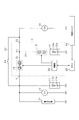
- FIG. 1 is a schematic diagram showing a peripheral configuration of the internal combustion engine according to the present embodiment.
- FIG. 2 is a flowchart showing a control process of the ECU according to the present embodiment.
- the vehicle travels using an engine corresponding to the internal combustion engine of the present disclosure as a main drive source.
- the vehicle includes an in-vehicle power supply device (hereinafter referred to as “power supply system”) and has an idling stop function for automatically stopping the internal combustion engine.
- the power supply system includes a rotating machine (ISG) 10, a lead storage battery 11, and a lithium ion storage battery 12 corresponding to the electric motor of the present disclosure.
- the power supply system includes a starter (St) 13, an electric load 14, a MOS switch 15, a SMR switch 16, and the like.
- the lithium ion storage battery 12, the MOS switch 15, and the SMR switch 16 are integrated by being housed in the same housing (for example, one housing case) and configured as a battery unit U.
- the battery unit U includes a control unit (battery control means) 20 for switching on and off the MOS switch 15 and the SMR switch 16.
- the control unit 20 is housed in the housing in a state of being mounted on the same substrate as the MOS switch 15 and the SMR switch 16.
- the battery unit U is provided with a first terminal T1 and a second terminal T2 (a plurality of external terminals).
- the lead storage battery 11, the starter 13, and the electric load 14 are connected to the first terminal T1 via a predetermined electric path.
- the rotating machine 10 is connected to the second terminal T2 via a predetermined electrical path.
- the first and second terminals T1 and T2 are also input / output terminals (large current input / output terminals) through which the input / output current of the rotating machine 10 flows.
- the rotating shaft of the rotating machine 10 is connected to the output shaft of the engine by, for example, a belt and can be driven in conjunction with the output shaft. For this reason, the rotating shaft of the rotating machine 10 is rotated by the rotation of the output shaft of the engine. Further, the output shaft of the engine is rotated by the rotation of the rotating shaft of the rotating machine 10.
- the rotating machine 10 has a power generation function for generating power (regenerative power generation) using rotational energy of the engine output shaft, axle, and the like, and a power output function (torque assist function) for applying torque to the engine output shaft. It is configured as an ISG (Integrated Starter Generator).
- the lead storage battery 11 and the lithium ion storage battery 12 are electrically connected to the rotating machine 10 in parallel. Therefore, the lead storage battery 11 and the lithium ion storage battery 12 are charged by the generated power of the rotating machine 10.
- the rotating machine 10 is driven by power feeding from the lead storage battery 11 and the lithium ion storage battery 12.
- the lead storage battery 11 is a well-known general-purpose storage battery.
- the lithium ion storage battery 12 is a storage battery (high-density storage battery) with less power loss in charge / discharge and higher output density and energy density than the lead storage battery 11.
- the lead storage battery 11 uses lead dioxide (PbO 2 ) as the positive electrode active material, lead (Pb) as the negative electrode active material, and sulfuric acid (H 2 SO 4 ) as the electrolyte.
- the lead storage battery 11 has a plurality of battery cells composed of such electrodes and an electrolytic solution connected in series.
- an oxide containing lithium (lithium metal composite oxide) is used for the positive electrode active material of the lithium ion storage battery 12.
- the oxide containing lithium include lithium cobaltate (LiCoO 2 ), lithium manganate (LiMn 2 O 4 ), lithium nickelate (LiNiO 2 ), and lithium iron phosphate (LiFePO 4 ).
- As the negative electrode active material of the lithium ion storage battery 12 an alloy containing carbon (C), graphite, lithium titanate (for example, Li x TiO 2 ), silicon (Si), or tin (Sn) is used.
- An organic electrolyte is used as the electrolyte of the lithium ion storage battery 12.
- the lithium ion storage battery 12 has a plurality of battery cells composed of such electrodes and an electrolytic solution connected in series.
- FIG. 1 the codes
- symbols 11a and 12a of FIG. 1 represent each battery cell aggregate
- FIG. Reference numerals 11b and 12b represent internal resistances of the lead storage battery 11 and the lithium ion storage battery 12, respectively.
- the electric load 14 requires a constant voltage such as a load that requires that the voltage of the supplied power is substantially constant, or a load that requires that the voltage of the supplied power fluctuates at least within a predetermined range and is stable. Includes load.
- Specific examples of the constant voltage request load include a navigation device and an audio device.
- stable operation of the device corresponding to the constant voltage required load can be realized by making the voltage fluctuation of the supplied power constant.
- Other constant voltage required loads include a headlight, a wiper, a blower fan for an air conditioner, a heater for a rear windshield, and the like.
- the battery unit U is provided with a first connection path 21 and a second connection path 22 (a plurality of electrical paths) that connect the first terminal T1, the second terminal T2, and the lithium ion storage battery 12 to each other.
- the MOS switch 15 (opening / closing means) is provided in the first connection path 21 that connects the first terminal T1 and the second terminal T2.
- the SMR switch 16 is provided in the second connection path 22 that connects the lithium ion storage battery 12 to the connection point N1 (battery connection point) of the first connection path 21.
- the MOS switch 15 and the SMR switch 16 include 2 ⁇ n MOSFETs (semiconductor switches).
- the MOS switch 15 and the SMR switch 16 are connected in series so that the parasitic diodes of the pair of MOSFETs are opposite to each other.
- the MOS switch 15 and the SMR switch 16 are turned off (open state)
- the current flowing through the first and second connection paths 21 and 22 provided with the switches is a parasitic diode. Is completely shut off.
- the power supply system is provided with a bypass path 23 that connects the lead storage battery 11 and the rotating machine 10 without using the MOS switch 15.
- the bypass path 23 includes an electrical path (path on the lead storage battery 11 side) connected to the first terminal T1 and an electrical path (path on the rotating machine 10 side) connected to the second terminal T2 to the battery unit U. Bypass and connect electrically.
- the bypass path 24 is provided with a bypass switch 24 that switches the electrical connection between the lead storage battery 11 side and the rotating machine 10 side to a cut-off state or a conductive state.
- the bypass switch 24 is a normally closed relay switch. Note that the bypass path 23 and the bypass switch 24 may be provided inside the battery unit U so as to bypass the MOS switch 15.
- the control unit 20 performs on / off switching (closing / opening control) for each of the MOS switch 15 and the SMR switch 16.
- the control unit 20 switches the MOS switch 15 on and off according to a predetermined control condition.
- a predetermined control condition it is determined whether or not the electric load 14 is discharged (load driving), whether or not the charging is performed by supplying power from the rotating machine 10, and idling stop control.
- the control unit 20 controls on / off of the SMR switch 16 as follows. In normal times, the SMR switch 16 is basically kept in the on state (closed state). When any abnormality occurs in the battery unit U, the rotating machine 10 or the like, the SMR switch 16 is turned off.
- control unit 20 is connected to an ECU 30 that is provided outside the battery unit U and corresponds to the control device of the present disclosure.
- the control unit 20 and the ECU 30 are connected via a communication network such as CAN, and can communicate with each other.
- the ECU 30 has a function of performing engine control (automatic engine stop and restart) including idling stop.
- engine control automated engine stop and restart
- the engine control when a predetermined automatic stop condition is satisfied, the engine is automatically stopped (corresponding to automatic stop means).
- the engine is restarted (corresponding to restarting means) when a predetermined restart condition is satisfied in the automatic stop state.
- ECU30 functions as an automatic stop means and a restart means.
- a changeover switch 40 for switching whether or not idling stop (automatic engine stop) is prohibited is connected to the ECU 30.
- the changeover switch 40 is switched from a non-prohibited state (off state) to a prohibited state (on state). That is, the changeover switch 40 functions as a user interface for switching whether or not idling stop is prohibited. Then, the driver indicates his intention to prohibit or not.
- a signal requesting prohibition of idling stop is transmitted to the ECU 30.
- the ECU 30 performs control for prohibiting the automatic stop of the engine (corresponding to an automatic stop prohibiting means).
- the ECU 30 receives the prohibition instruction from the driver via the changeover switch 40 and performs control for prohibiting the automatic stop of the engine.
- the ECU 30 reduces the engine output and increases the output of the rotating machine 10 so that the rotating machine 10 assists the engine output (the rotating machine 10 applies torque to the engine output shaft). (Torque assist control) is performed (corresponding to the assisting means).
- the ECU 30 performs control for prohibiting engine output assistance by the rotating machine 10 (corresponding to assistance prohibiting means).
- the ECU 30 functions as an automatic stop prohibiting unit, an auxiliary unit, and an auxiliary prohibiting unit.
- Rotating machine 10 generates electricity by the rotational energy of the engine output shaft.
- the electric power generated by the rotating machine 10 is supplied to the electric load 14 and supplied to the lead storage battery 11 and the lithium ion storage battery 12 for charging.
- electric power is supplied from the lead storage battery 11 and the lithium ion storage battery 12 to the electric load 14 and discharged.
- the discharge amount and the charge amount of the lead storage battery 11 and the lithium ion storage battery 12 are determined based on the SOC (the remaining capacity of the battery; the ratio of the actual charge amount to the charge amount at the time of full charge). It is controlled in the range that does not become (SOC usage range).
- the rotating machine 10 generates power by using regenerative energy when the traveling vehicle is decelerated (for example, during braking).
- the electric power generated by the rotating machine 10 is charged to the lead storage battery 11 and the lithium ion storage battery 12 (mainly the lithium ion storage battery 12).
- regenerative power generation and regenerative charging are performed when the traveling vehicle is decelerated. Note that regenerative power generation and regenerative charging are performed when conditions such as that the traveling vehicle is in a decelerating state (when decelerating) or that fuel is not being injected into the engine (when fuel injection is cut) are established.
- the driver turns on the changeover switch 40 to enable the idling stop prohibition.
- the engine cannot be automatically stopped (idling stop cannot be performed). That is, the engine performs idling until the prohibition of idling stop is released.
- the fuel efficiency becomes worse (the fuel efficiency decreases) as compared with the case where the engine is automatically stopped (when idling stop is performed).
- the ECU 30 executes the control process shown in FIG. Among them, the ECU 30 performs control to decrease the output of the engine and increase the output of the rotating machine 10 when the automatic engine stop condition is satisfied when the idling stop prohibition is valid. Thereby, in this embodiment, in the vehicle provided with the rotating machine 10, it is possible to suppress a reduction in fuel consumption when idling is performed during the idling stop prohibition period.
- control process engine control process of the ECU 30 according to the present embodiment will be described with reference to FIG.
- the processing shown in FIG. 2 is repeatedly executed at predetermined intervals by the ECU 30 while the power is on.
- the ECU 30 determines whether or not an automatic engine stop condition is satisfied (S100).
- the automatic stop condition referred to here corresponds to a driving operation, a vehicle situation, or the like that it is better to perform idling stop. Specifically, the following conditions are mentioned as an example.
- Acc accelerator operation amount
- Acci traveling vehicle speed ve is lower than a predetermined reference speed ve0 (ve ⁇ ve0 (predetermined value)).
- the ECU 30 When the idling stop prohibition condition (automatic stop prohibition condition) is not satisfied, the ECU 30 satisfies at least one of [i] and [ii] except [iii] among the above [i] to [iii] It is determined whether or not to do. As a result, the ECU 30 determines that the automatic engine stop condition is satisfied when at least one of the above [i] and [ii] conditions is satisfied. As described above, in this process, it is determined whether or not an automatic stop condition (an automatic stop condition other than the non-establishment of the prohibition condition) that does not include the non-satisfaction of the idling stop prohibition condition is satisfied.
- an automatic stop condition an automatic stop condition other than the non-establishment of the prohibition condition
- the ECU 30 determines that the automatic stop condition that does not include the absence of the idling stop prohibition condition is not satisfied (S100: NO), the ECU 30 continues the current engine drive and ends the present process. On the other hand, when the ECU 30 determines that the automatic stop condition that does not include the failure of the idling stop prohibition condition is satisfied (S100: YES), the ECU 30 proceeds to the process of S110.
- the ECU 30 determines whether or not an idling stop prohibition condition is satisfied (S110).
- the idling stop prohibition condition mentioned here corresponds to acceptance of an idling stop prohibition request, a vehicle situation where it is better to prohibit idling stop, and the like. Specifically, the following conditions are mentioned as an example. [1] When the changeover switch 40 is in the on state (the prohibition instruction from the driver is accepted and idling stop prohibition is valid). [2] The vehicle is traveling on a road (slope or step) larger than a predetermined reference slope. [3] When the vehicle's start response is required. In situations where the vehicle's start response is required, for example, the vehicle temporarily stops in the middle of an intersection to turn right or left.
- the situation where the vehicle start response is required is set as one of the idling stop prohibition conditions.
- the ECU 30 determines whether or not at least one of the above conditions [1] to [3] is satisfied. As a result, the ECU 30 determines that the idling stop prohibition condition is satisfied when at least one of the above conditions [1] to [3] is satisfied.
- ECU30 will transfer to the process of S120, when it determines with the idling stop prohibition conditions having been satisfied (S110: YES).
- the lower limit value of the use permission (capacity range permitted to be used during normal use) is reduced by a predetermined value for the battery capacities of the lead storage battery 11 and the lithium ion storage battery 12.
- the ECU 30 determines whether or not an auxiliary prohibition condition for prohibiting torque assist (engine output assist) by the rotating machine 10 is established (S120).
- the assistance prohibition condition mentioned here corresponds to a vehicle situation or the like for which it is better to prohibit torque assist. Specifically, the following conditions are mentioned as an example.
- ECU30 will transfer to the process of S150, when it determines with the assistance prohibition conditions having been satisfied (S120: YES). Then, the ECU 30 performs normal idling without performing torque assist by the rotating machine 10 (S150). On the other hand, when determining that the auxiliary prohibition condition is not satisfied (S120: NO), the ECU 30 proceeds to the process of S130. Then, the ECU 30 performs control for reducing the engine speed during idling (control for reducing the engine output) (S130), and proceeds to the processing of S140.
- the ECU 30 performs torque assist by the rotating machine 10 (S140). Specifically, the ECU 30 assists the engine output by applying the torque to the output shaft of the engine by the amount corresponding to the decrease in the rotational speed of the engine. Then, the ECU 30 performs idling in a state where torque assist is performed by the rotating machine 10 (S150). Thus, in this process, the decrease in the engine output due to the reduction in the rotational speed is compensated by the output of the rotating machine 10.
- ECU30 will transfer to the process of S160, when it determines with the idling stop prohibition conditions not being satisfied (S110: NO). Then, the ECU 30 stops the engine and performs idling stop (S160), and the process proceeds to S170.
- the ECU 30 determines whether or not an elapsed time (establishment time of the restart condition) from when the idling stop is performed until the engine restart condition is satisfied is within a predetermined time (first predetermined time) (S170).
- the restart condition mentioned here include, for example, when the accelerator operation amount Acc is larger than a predetermined reference operation amount Acc0 (Acc> Acc0).
- the time when the energy efficiency is higher than when the engine is automatically stopped (idling stop) is set as the predetermined time (first predetermined time). If it is determined that the restart condition is established within a predetermined time (first predetermined time) (S170: YES), the ECU 30 proceeds to the process of S180.
- ECU 30 determines whether or not the restart condition is established frequently within a predetermined time (higher than the predetermined frequency) (S180). Specifically, the ECU 30 counts the number of times that the restart condition is established within the predetermined time (the number of positive determinations). Then, the ECU 30 determines whether or not the counted number of affirmative determinations is greater than a first predetermined number that represents the high frequency establishment criterion. In addition, before it is determined that the number of positive determinations is greater than the first predetermined number of times, when it is determined that the restart condition is not established within a predetermined time, the count value of the number of positive determinations is initialized ( Reset the count value to zero).
- ECU30 will transfer to the process of S200, when it determines with the establishment frequency of the restart conditions within the predetermined time not being high frequency (S180: NO). And ECU30 restarts an engine (S200) and complete
- the ECU 30 determines that the frequency of establishment of the restart condition within the predetermined time is high (S180: YES)
- the ECU 30 proceeds to the process of S190. Then, the ECU 30 lowers the value of the reference speed ve0 of the automatic stop condition [ii] by the first predetermined value (S190), and restarts the engine (S200).
- the ECU 30 will transfer to the process of S210, when it determines with the establishment time of restart conditions not being within the predetermined time (1st predetermined time) (S170: NO).
- the ECU 30 determines whether or not the frequency of establishment of the restart condition within a predetermined time is low (lower than the predetermined frequency) (S210). Specifically, the ECU 30 counts the number of times that the restart condition is not established within a predetermined time (the number of negative determinations). Then, the ECU 30 determines whether or not the counted number of negative determinations is smaller than a second predetermined number that represents a criterion for low establishment frequency. If it is determined that the establishment time of the restart condition is within the predetermined time before it is determined that the number of negative determinations is less than the second predetermined number of times, the count value of the negative determination number of times is initialized. .
- ECU30 will transfer to the process of S200, when it determines with the establishment frequency of the restart conditions within the predetermined time not being low frequency (S210: NO). And ECU30 restarts an engine (S200) and complete
- the control device (ECU 30) according to the present embodiment has the following effects due to the above configuration.
- the idling stop prohibition condition includes that the changeover switch 40 for switching whether or not to prohibit idling stop is in an on state (prohibiting idling stop is valid).
- the changeover switch 40 is provided near the driver's seat.
- the driver can request that the idling stop be prohibited by pressing the changeover switch 40.
- the control device prohibits idling stop according to this request.
- the above-described control process is executed even when idling stop is prohibited by the user's intention. Thereby, a fuel consumption fall can be suppressed to the minimum.
- the idling stop prohibition condition includes that the vehicle is traveling on a road larger than a predetermined reference gradient. For example, when idling stop is executed when the vehicle is climbing an uphill that is larger than a predetermined reference gradient, the driving force (climbing up) required for the vehicle to climb after the engine restarts. It takes time to get power. As a result, the vehicle may have insufficient driving force and go down the road. Therefore, idling stop is prohibited under such conditions.
- the above-described control process is executed even when idling stop is prohibited because the vehicle is climbing up. Thereby, a fuel consumption fall can be suppressed to the minimum.
- idling stop is executed when the vehicle is descending a downhill that is larger than a predetermined reference gradient, the vehicle accelerates at an unintended speed when the engine is restarted. There is a possibility. Therefore, idling stop is prohibited under such conditions.
- the above-described control process is executed even when idling stop is prohibited because the vehicle is on a downhill. Thereby, a fuel consumption fall can be suppressed.
- the idling stop prohibition condition includes a situation in which vehicle start response is required.
- the situation where the start response is required corresponds to, for example, a case where the operation amount of the steering wheel is larger than a predetermined operation amount.
- the vehicle is only temporarily stopped for safety confirmation, and if driving safety is confirmed, the vehicle is likely to start immediately, and the engine is automatically stopped (idling stop).
- the engine must be restarted immediately. Therefore, there is a possibility that the fuel consumption will be worse (fuel consumption will be reduced) when the engine is automatically stopped than when the engine is not automatically stopped.
- the above-described control process is executed even when idling stop is prohibited because the vehicle is temporarily stopped in the middle of the intersection. Thereby, the fall of drivability and the fuel consumption fall can be suppressed.
- the automatic stop is performed on the condition that the restart condition is established frequently before the predetermined time (first predetermined time) elapses after the engine is automatically stopped.
- the reference speed ve0 of the condition [ii] is lowered by a predetermined value (first predetermined value) and reset (set again).
- control device when it is assumed that there are many situations where the engine is restarted immediately after the automatic stop of the engine, the control device changes to an automatic stop condition that makes it difficult to satisfy the condition. Thereby, implementation of the idling stop which is not required can be suppressed.
- the automatic stop condition is provided on the condition that the restart condition is established less frequently before the predetermined time (first predetermined time) elapses after the engine is automatically stopped.
- the reference speed ve0 of [ii] is raised by a predetermined value (second predetermined value) and set again.
- the control device when it is assumed that there are few situations in which the engine is restarted immediately after the automatic stop of the engine, the control device is changed to an automatic stop condition that makes it easy to satisfy the condition. Thereby, idling stop can be implemented actively.
- the auxiliary prohibition condition includes that it is predicted that a time during which at least one of the lead storage battery 11 and the lithium ion storage battery 12 cannot be charged (non-chargeable time) is longer than a predetermined time (second predetermined time). For example, when traveling in a congested section is predicted in the future in the vehicle situation, it is considered difficult to perform regenerative charging during that period (during traveling in a congested section). In such a situation, when torque assist (engine output assistance) by the rotating machine 10 is performed, charging is not performed but only discharging is performed. Therefore, the electric charge accumulated in the lead storage battery 11 and the lithium ion storage battery 12 may be exhausted during torque assist.
- the auxiliary prohibition condition includes a case where the discharge amount of at least one of the lead storage battery 11 and the lithium ion storage battery 12 in a predetermined period is larger than the charge amount.
- torque assist by the rotating machine 10 is prohibited when the discharge amount of at least one of the lead storage battery 11 and the lithium ion storage battery 12 exceeds the charge amount in a predetermined period.
- the lower limit value of the use permission is lowered by a predetermined value for the battery capacities of the lead storage battery 11 and the lithium ion storage battery 12.
- the engine is not automatically stopped, so that it is not necessary to secure a charge amount necessary for restart.
- the lead storage battery 11 and the lithium ion storage battery 12 can be used until they have a low capacity that is not normally used.
- the lithium ion storage battery 12 is applied as a storage battery (high-density storage battery) with less power loss during charging and discharging and higher output density and energy density than the lead storage battery 11, but the present invention is not limited to this.
- a nickel metal hydride battery may be used.
- the following conditions are used as idling stop prohibition conditions.
- the idling stop prohibition condition is satisfied. This does not apply to the idling stop prohibition conditions.
- new conditions may be added to the above [1] to [3]. Specifically, at least one of the following conditions may be added as appropriate.
- the lower limit value of the use permission is reduced by a predetermined value for the battery capacity of the lead storage battery 11 and the lithium ion storage battery 12, but this is not limited thereto. Absent. As another example, even in the above case, it is not necessary to lower the lower limit value of the use permission for the battery capacities of the lead storage battery 11 and the lithium ion storage battery 12.
- the control device executes a determination process as to whether or not the engine restart condition is satisfied within a predetermined time, but is not limited thereto.
- a determination process as to whether or not an engine restart condition is satisfied while the vehicle is traveling may be executed. Even when the engine is automatically stopped (idling stop), the situation where the restart condition is satisfied during vehicle travel corresponds to, for example, the case where the vehicle repeats slow running and normal travel due to traffic congestion. In this case, even if the engine is automatically stopped, since the engine is restarted immediately, there is a possibility that the fuel efficiency is deteriorated (the fuel efficiency is reduced).
- the reference speed ve0 of the automatic stop condition [ii] is reduced by a predetermined value (first predetermined value) and set again.
- the restart condition is frequently established before the predetermined time (first predetermined time) elapses after the control device automatically stops the engine.
- the main determination process (the process of S180) may not be executed (may be omitted).
- the reference speed ve0 of the automatic stop condition [ii] is decreased by a predetermined value and reset. If the driver immediately restarts the engine after the engine has been automatically stopped, the fuel consumption may be worse (lower fuel consumption) when the engine is automatically stopped than when the engine is not automatically stopped. is there.
- the reference speed ve0 of the automatic stop condition [ii] is reduced by a predetermined value and set on the condition that the restart condition is satisfied before the predetermined time elapses after the engine is automatically stopped. cure.
- this modification when a situation where the engine is restarted immediately after the engine is automatically stopped is changed to an automatic stop condition that makes it difficult to satisfy the condition. Thereby, implementation of the idling stop which is not required can be suppressed.
- the frequency of establishment of the restart condition is low before the predetermined time (first predetermined time) elapses after the control device automatically stops the engine.
- the main determination process (the process of S210) may not be executed (may be omitted).
- the reference speed ve0 of the automatic stop condition [ii] is adjusted (increase / decrease) each time it is determined whether or not the engine restart condition is satisfied before the predetermined time elapses. . Thereby, whether or not idling stop can be set can be set according to the vehicle situation.
Landscapes
- Engineering & Computer Science (AREA)
- Mechanical Engineering (AREA)
- Combustion & Propulsion (AREA)
- Chemical & Material Sciences (AREA)
- Transportation (AREA)
- Automation & Control Theory (AREA)
- General Engineering & Computer Science (AREA)
- Power Engineering (AREA)
- Sustainable Energy (AREA)
- Sustainable Development (AREA)
- Life Sciences & Earth Sciences (AREA)
- Control Of Vehicle Engines Or Engines For Specific Uses (AREA)
- Output Control And Ontrol Of Special Type Engine (AREA)
- Hybrid Electric Vehicles (AREA)
- Electric Propulsion And Braking For Vehicles (AREA)
Priority Applications (3)
| Application Number | Priority Date | Filing Date | Title |
|---|---|---|---|
| US15/575,132 US10406909B2 (en) | 2015-05-22 | 2016-05-18 | Control device for internal combustion engine |
| DE112016002323.5T DE112016002323T5 (de) | 2015-05-22 | 2016-05-18 | Steuergerät für eine Brennkraftmaschine |
| CN201680029419.7A CN107614339A (zh) | 2015-05-22 | 2016-05-18 | 内燃机的控制装置 |
Applications Claiming Priority (2)
| Application Number | Priority Date | Filing Date | Title |
|---|---|---|---|
| JP2015-104381 | 2015-05-22 | ||
| JP2015104381A JP6459774B2 (ja) | 2015-05-22 | 2015-05-22 | 内燃機関の制御装置 |
Publications (1)
| Publication Number | Publication Date |
|---|---|
| WO2016190191A1 true WO2016190191A1 (ja) | 2016-12-01 |
Family
ID=57394120
Family Applications (1)
| Application Number | Title | Priority Date | Filing Date |
|---|---|---|---|
| PCT/JP2016/064739 Ceased WO2016190191A1 (ja) | 2015-05-22 | 2016-05-18 | 内燃機関の制御装置 |
Country Status (5)
| Country | Link |
|---|---|
| US (1) | US10406909B2 (enExample) |
| JP (1) | JP6459774B2 (enExample) |
| CN (1) | CN107614339A (enExample) |
| DE (1) | DE112016002323T5 (enExample) |
| WO (1) | WO2016190191A1 (enExample) |
Families Citing this family (7)
| Publication number | Priority date | Publication date | Assignee | Title |
|---|---|---|---|---|
| JP7049808B2 (ja) * | 2017-11-08 | 2022-04-07 | 株式会社デンソー | 制動制御装置 |
| JP7059945B2 (ja) * | 2019-01-23 | 2022-04-26 | 株式会社デンソー | 電源システム |
| JP2020180566A (ja) * | 2019-04-24 | 2020-11-05 | 本田技研工業株式会社 | 内燃機関の制御装置 |
| US11281217B2 (en) * | 2019-06-25 | 2022-03-22 | Ford Global Technologies, Llc | Enhanced vehicle operation |
| CN111456875B (zh) * | 2020-03-23 | 2022-05-06 | 江门市大长江集团有限公司 | 怠速启停控制方法及装置、控制器和计算机可读存储介质 |
| JP7447670B2 (ja) * | 2020-05-15 | 2024-03-12 | トヨタ自動車株式会社 | 自律移動装置制御システム、その制御方法及びその制御プログラム |
| JP7615792B2 (ja) * | 2021-03-16 | 2025-01-17 | スズキ株式会社 | ハイブリッド車両の制御装置 |
Citations (5)
| Publication number | Priority date | Publication date | Assignee | Title |
|---|---|---|---|---|
| JPH0939613A (ja) * | 1995-08-03 | 1997-02-10 | Aisin Aw Co Ltd | 車両用駆動装置の制御装置 |
| JP2000205000A (ja) * | 1999-01-13 | 2000-07-25 | Nissan Motor Co Ltd | ハイブリッド車両の制御装置 |
| JP2000265870A (ja) * | 1999-03-19 | 2000-09-26 | Unisia Jecs Corp | ハイブリッド車両の制御装置 |
| JP2001182581A (ja) * | 1999-12-24 | 2001-07-06 | Fuji Heavy Ind Ltd | エンジンのアイドル制御装置 |
| JP2005291158A (ja) * | 2004-04-02 | 2005-10-20 | Nissan Motor Co Ltd | 内燃機関の発電制御装置 |
Family Cites Families (16)
| Publication number | Priority date | Publication date | Assignee | Title |
|---|---|---|---|---|
| US5801499A (en) | 1995-07-11 | 1998-09-01 | Aisin Aw Co., Ltd. | Control system for a vehicular drive unit |
| JP3846349B2 (ja) | 2002-03-29 | 2006-11-15 | マツダ株式会社 | パワートレインの制御装置 |
| JP4650688B2 (ja) | 2006-02-03 | 2011-03-16 | 株式会社デンソー | 絶縁ゲート型トランジスタ駆動回路装置 |
| EP2287488B1 (en) * | 2008-06-04 | 2014-01-22 | Nissan Motor Co., Ltd. | Fastening pressure control device for starting friction element at time of controlling idle stop of vehicle |
| JP4730713B2 (ja) * | 2008-08-08 | 2011-07-20 | 株式会社デンソー | エンジン自動停止・始動制御装置 |
| JP4678442B2 (ja) | 2009-03-12 | 2011-04-27 | 株式会社デンソー | 車両制御装置 |
| EP2272722B1 (en) | 2009-07-01 | 2015-04-08 | Denso Corporation | Power source apparatus for vehicle |
| JP5520201B2 (ja) * | 2010-11-30 | 2014-06-11 | 富士重工業株式会社 | 車両のアイドルストップ制御装置 |
| JP2012127315A (ja) | 2010-12-17 | 2012-07-05 | Mitsubishi Motors Corp | アイドルストップ車両の制御装置 |
| JP5299576B1 (ja) * | 2011-12-15 | 2013-09-25 | トヨタ自動車株式会社 | ハイブリッド車両の制御装置 |
| RU2570996C1 (ru) * | 2012-01-24 | 2015-12-20 | Тойота Дзидося Кабусики Кайся | Устройство управления транспортным средством, транспортное средство и способ управления транспортным средством |
| EP2894317B1 (en) * | 2012-09-10 | 2018-01-31 | Nissan Motor Co., Ltd | Idle stop control device for vehicle equipped with automatic manual transmission |
| JP5575203B2 (ja) * | 2012-10-24 | 2014-08-20 | 三菱電機株式会社 | 車両の発電装置および発電制御方法 |
| US10253714B2 (en) * | 2013-05-20 | 2019-04-09 | Ford Global Technologies, Llc | Stop/start control based on repeated driving patterns |
| JP6034504B2 (ja) * | 2013-09-30 | 2016-11-30 | 本田技研工業株式会社 | アイドルストップ制御装置 |
| US9074571B1 (en) * | 2013-12-17 | 2015-07-07 | Ford Global Technologies, Llc | Vehicle and method of controlling an engine auto-stop and restart |
-
2015
- 2015-05-22 JP JP2015104381A patent/JP6459774B2/ja active Active
-
2016
- 2016-05-18 DE DE112016002323.5T patent/DE112016002323T5/de not_active Ceased
- 2016-05-18 US US15/575,132 patent/US10406909B2/en active Active
- 2016-05-18 CN CN201680029419.7A patent/CN107614339A/zh not_active Withdrawn
- 2016-05-18 WO PCT/JP2016/064739 patent/WO2016190191A1/ja not_active Ceased
Patent Citations (5)
| Publication number | Priority date | Publication date | Assignee | Title |
|---|---|---|---|---|
| JPH0939613A (ja) * | 1995-08-03 | 1997-02-10 | Aisin Aw Co Ltd | 車両用駆動装置の制御装置 |
| JP2000205000A (ja) * | 1999-01-13 | 2000-07-25 | Nissan Motor Co Ltd | ハイブリッド車両の制御装置 |
| JP2000265870A (ja) * | 1999-03-19 | 2000-09-26 | Unisia Jecs Corp | ハイブリッド車両の制御装置 |
| JP2001182581A (ja) * | 1999-12-24 | 2001-07-06 | Fuji Heavy Ind Ltd | エンジンのアイドル制御装置 |
| JP2005291158A (ja) * | 2004-04-02 | 2005-10-20 | Nissan Motor Co Ltd | 内燃機関の発電制御装置 |
Also Published As
| Publication number | Publication date |
|---|---|
| CN107614339A (zh) | 2018-01-19 |
| JP6459774B2 (ja) | 2019-01-30 |
| JP2016215892A (ja) | 2016-12-22 |
| US20180141427A1 (en) | 2018-05-24 |
| DE112016002323T5 (de) | 2018-03-01 |
| US10406909B2 (en) | 2019-09-10 |
Similar Documents
| Publication | Publication Date | Title |
|---|---|---|
| JP6380171B2 (ja) | 電源システム | |
| WO2016190191A1 (ja) | 内燃機関の制御装置 | |
| JP6024537B2 (ja) | 車載電源システム | |
| JP5234052B2 (ja) | 電源装置 | |
| CN108656968B (zh) | 车辆用电源装置 | |
| JP6371791B2 (ja) | 車両用電源装置 | |
| JP5911928B2 (ja) | 電源システム、および車両 | |
| JP2014177213A (ja) | 車載電源システム | |
| CN110316176B (zh) | 控制装置 | |
| CN109314399B (zh) | 车载电源系统 | |
| JP6677177B2 (ja) | 制御装置 | |
| CN105083040A (zh) | 电源控制装置 | |
| JP7010108B2 (ja) | 制御装置 | |
| CN108437969B (zh) | 车辆用控制装置 | |
| JP2017103080A (ja) | 電動車両の電池システム | |
| US11198368B2 (en) | Vehicular charging control system | |
| JP5556636B2 (ja) | 電気自動車およびその異常判定方法 | |
| US11535119B2 (en) | Control of the state of charge of an electrically powered vehicle when traveling on a hill | |
| JP6277859B2 (ja) | 電源制御装置 | |
| JP7373113B2 (ja) | 車両用電源制御装置 | |
| JP5885236B2 (ja) | 車両の電源装置 | |
| JP6488995B2 (ja) | 車載電源システムの制御装置 | |
| CN114103925B (zh) | Eco充电模式 | |
| JP2004022384A (ja) | ハイブリッド自動車 | |
| JP2020183161A (ja) | 電源装置、電源システム |
Legal Events
| Date | Code | Title | Description |
|---|---|---|---|
| 121 | Ep: the epo has been informed by wipo that ep was designated in this application |
Ref document number: 16799897 Country of ref document: EP Kind code of ref document: A1 |
|
| WWE | Wipo information: entry into national phase |
Ref document number: 15575132 Country of ref document: US |
|
| WWE | Wipo information: entry into national phase |
Ref document number: 112016002323 Country of ref document: DE |
|
| 122 | Ep: pct application non-entry in european phase |
Ref document number: 16799897 Country of ref document: EP Kind code of ref document: A1 |