WO2016158410A1 - 基板処理装置および基板処理方法 - Google Patents
基板処理装置および基板処理方法 Download PDFInfo
- Publication number
- WO2016158410A1 WO2016158410A1 PCT/JP2016/058288 JP2016058288W WO2016158410A1 WO 2016158410 A1 WO2016158410 A1 WO 2016158410A1 JP 2016058288 W JP2016058288 W JP 2016058288W WO 2016158410 A1 WO2016158410 A1 WO 2016158410A1
- Authority
- WO
- WIPO (PCT)
- Prior art keywords
- substrate
- liquid
- liquid film
- processing
- film
- Prior art date
- Legal status (The legal status is an assumption and is not a legal conclusion. Google has not performed a legal analysis and makes no representation as to the accuracy of the status listed.)
- Ceased
Links
Images





Classifications
-
- H—ELECTRICITY
- H10—SEMICONDUCTOR DEVICES; ELECTRIC SOLID-STATE DEVICES NOT OTHERWISE PROVIDED FOR
- H10P—GENERIC PROCESSES OR APPARATUS FOR THE MANUFACTURE OR TREATMENT OF DEVICES COVERED BY CLASS H10
- H10P72/00—Handling or holding of wafers, substrates or devices during manufacture or treatment thereof
- H10P72/04—Apparatus for manufacture or treatment
- H10P72/0402—Apparatus for fluid treatment
- H10P72/0406—Apparatus for fluid treatment for cleaning followed by drying, rinsing, stripping, blasting or the like
- H10P72/0411—Apparatus for fluid treatment for cleaning followed by drying, rinsing, stripping, blasting or the like for wet cleaning or washing
-
- B—PERFORMING OPERATIONS; TRANSPORTING
- B08—CLEANING
- B08B—CLEANING IN GENERAL; PREVENTION OF FOULING IN GENERAL
- B08B3/00—Cleaning by methods involving the use or presence of liquid or steam
- B08B3/02—Cleaning by the force of jets or sprays
- B08B3/024—Cleaning by means of spray elements moving over the surface to be cleaned
-
- H—ELECTRICITY
- H10—SEMICONDUCTOR DEVICES; ELECTRIC SOLID-STATE DEVICES NOT OTHERWISE PROVIDED FOR
- H10P—GENERIC PROCESSES OR APPARATUS FOR THE MANUFACTURE OR TREATMENT OF DEVICES COVERED BY CLASS H10
- H10P72/00—Handling or holding of wafers, substrates or devices during manufacture or treatment thereof
- H10P72/04—Apparatus for manufacture or treatment
- H10P72/0402—Apparatus for fluid treatment
- H10P72/0406—Apparatus for fluid treatment for cleaning followed by drying, rinsing, stripping, blasting or the like
- H10P72/0411—Apparatus for fluid treatment for cleaning followed by drying, rinsing, stripping, blasting or the like for wet cleaning or washing
- H10P72/0414—Apparatus for fluid treatment for cleaning followed by drying, rinsing, stripping, blasting or the like for wet cleaning or washing using mainly spraying means, e.g. nozzles
-
- B—PERFORMING OPERATIONS; TRANSPORTING
- B08—CLEANING
- B08B—CLEANING IN GENERAL; PREVENTION OF FOULING IN GENERAL
- B08B3/00—Cleaning by methods involving the use or presence of liquid or steam
- B08B3/04—Cleaning involving contact with liquid
- B08B3/10—Cleaning involving contact with liquid with additional treatment of the liquid or of the object being cleaned, e.g. by heat, by electricity or by vibration
- B08B3/106—Cleaning involving contact with liquid with additional treatment of the liquid or of the object being cleaned, e.g. by heat, by electricity or by vibration by boiling the liquid
-
- H—ELECTRICITY
- H10—SEMICONDUCTOR DEVICES; ELECTRIC SOLID-STATE DEVICES NOT OTHERWISE PROVIDED FOR
- H10P—GENERIC PROCESSES OR APPARATUS FOR THE MANUFACTURE OR TREATMENT OF DEVICES COVERED BY CLASS H10
- H10P52/00—Grinding, lapping or polishing of wafers, substrates or parts of devices
-
- H—ELECTRICITY
- H10—SEMICONDUCTOR DEVICES; ELECTRIC SOLID-STATE DEVICES NOT OTHERWISE PROVIDED FOR
- H10P—GENERIC PROCESSES OR APPARATUS FOR THE MANUFACTURE OR TREATMENT OF DEVICES COVERED BY CLASS H10
- H10P70/00—Cleaning of wafers, substrates or parts of devices
- H10P70/10—Cleaning before device manufacture, i.e. Begin-Of-Line process
- H10P70/15—Cleaning before device manufacture, i.e. Begin-Of-Line process by wet cleaning only
-
- H—ELECTRICITY
- H10—SEMICONDUCTOR DEVICES; ELECTRIC SOLID-STATE DEVICES NOT OTHERWISE PROVIDED FOR
- H10P—GENERIC PROCESSES OR APPARATUS FOR THE MANUFACTURE OR TREATMENT OF DEVICES COVERED BY CLASS H10
- H10P70/00—Cleaning of wafers, substrates or parts of devices
- H10P70/20—Cleaning during device manufacture
-
- H—ELECTRICITY
- H10—SEMICONDUCTOR DEVICES; ELECTRIC SOLID-STATE DEVICES NOT OTHERWISE PROVIDED FOR
- H10P—GENERIC PROCESSES OR APPARATUS FOR THE MANUFACTURE OR TREATMENT OF DEVICES COVERED BY CLASS H10
- H10P72/00—Handling or holding of wafers, substrates or devices during manufacture or treatment thereof
- H10P72/04—Apparatus for manufacture or treatment
- H10P72/0402—Apparatus for fluid treatment
- H10P72/0406—Apparatus for fluid treatment for cleaning followed by drying, rinsing, stripping, blasting or the like
- H10P72/0408—Apparatus for fluid treatment for cleaning followed by drying, rinsing, stripping, blasting or the like for drying
-
- H—ELECTRICITY
- H10—SEMICONDUCTOR DEVICES; ELECTRIC SOLID-STATE DEVICES NOT OTHERWISE PROVIDED FOR
- H10P—GENERIC PROCESSES OR APPARATUS FOR THE MANUFACTURE OR TREATMENT OF DEVICES COVERED BY CLASS H10
- H10P72/00—Handling or holding of wafers, substrates or devices during manufacture or treatment thereof
- H10P72/04—Apparatus for manufacture or treatment
- H10P72/0402—Apparatus for fluid treatment
- H10P72/0418—Apparatus for fluid treatment for etching
- H10P72/0422—Apparatus for fluid treatment for etching for wet etching
- H10P72/0424—Apparatus for fluid treatment for etching for wet etching using mainly spraying means, e.g. nozzles
-
- H—ELECTRICITY
- H10—SEMICONDUCTOR DEVICES; ELECTRIC SOLID-STATE DEVICES NOT OTHERWISE PROVIDED FOR
- H10P—GENERIC PROCESSES OR APPARATUS FOR THE MANUFACTURE OR TREATMENT OF DEVICES COVERED BY CLASS H10
- H10P72/00—Handling or holding of wafers, substrates or devices during manufacture or treatment thereof
- H10P72/04—Apparatus for manufacture or treatment
- H10P72/0431—Apparatus for thermal treatment
-
- H—ELECTRICITY
- H10—SEMICONDUCTOR DEVICES; ELECTRIC SOLID-STATE DEVICES NOT OTHERWISE PROVIDED FOR
- H10P—GENERIC PROCESSES OR APPARATUS FOR THE MANUFACTURE OR TREATMENT OF DEVICES COVERED BY CLASS H10
- H10P72/00—Handling or holding of wafers, substrates or devices during manufacture or treatment thereof
- H10P72/04—Apparatus for manufacture or treatment
- H10P72/0448—Apparatus for applying a liquid, a resin, an ink or the like
-
- H—ELECTRICITY
- H10—SEMICONDUCTOR DEVICES; ELECTRIC SOLID-STATE DEVICES NOT OTHERWISE PROVIDED FOR
- H10P—GENERIC PROCESSES OR APPARATUS FOR THE MANUFACTURE OR TREATMENT OF DEVICES COVERED BY CLASS H10
- H10P72/00—Handling or holding of wafers, substrates or devices during manufacture or treatment thereof
- H10P72/10—Handling or holding of wafers, substrates or devices during manufacture or treatment thereof using carriers specially adapted therefor, e.g. front opening unified pods [FOUP]
- H10P72/14—Vertical carrier comprising wall type elements whereby the substrates are horizontally supported, e.g. comprising sidewalls
-
- H—ELECTRICITY
- H10—SEMICONDUCTOR DEVICES; ELECTRIC SOLID-STATE DEVICES NOT OTHERWISE PROVIDED FOR
- H10P—GENERIC PROCESSES OR APPARATUS FOR THE MANUFACTURE OR TREATMENT OF DEVICES COVERED BY CLASS H10
- H10P72/00—Handling or holding of wafers, substrates or devices during manufacture or treatment thereof
- H10P72/70—Handling or holding of wafers, substrates or devices during manufacture or treatment thereof for supporting or gripping
- H10P72/76—Handling or holding of wafers, substrates or devices during manufacture or treatment thereof for supporting or gripping using mechanical means, e.g. clamps or pinches
- H10P72/7604—Handling or holding of wafers, substrates or devices during manufacture or treatment thereof for supporting or gripping using mechanical means, e.g. clamps or pinches the wafers being placed on a susceptor, stage or support
- H10P72/7618—Handling or holding of wafers, substrates or devices during manufacture or treatment thereof for supporting or gripping using mechanical means, e.g. clamps or pinches the wafers being placed on a susceptor, stage or support characterised by a movable susceptor, stage or support, others than those only rotating on their own vertical axis, e.g. susceptors on a rotating carrousel
-
- H—ELECTRICITY
- H10—SEMICONDUCTOR DEVICES; ELECTRIC SOLID-STATE DEVICES NOT OTHERWISE PROVIDED FOR
- H10P—GENERIC PROCESSES OR APPARATUS FOR THE MANUFACTURE OR TREATMENT OF DEVICES COVERED BY CLASS H10
- H10P76/00—Manufacture or treatment of masks on semiconductor bodies, e.g. by lithography or photolithography
-
- H—ELECTRICITY
- H10—SEMICONDUCTOR DEVICES; ELECTRIC SOLID-STATE DEVICES NOT OTHERWISE PROVIDED FOR
- H10P—GENERIC PROCESSES OR APPARATUS FOR THE MANUFACTURE OR TREATMENT OF DEVICES COVERED BY CLASS H10
- H10P95/00—Generic processes or apparatus for manufacture or treatments not covered by the other groups of this subclass
- H10P95/90—Thermal treatments, e.g. annealing or sintering
Definitions
- the present invention relates to a substrate processing apparatus and a substrate processing method for processing a substrate.
- substrate In a manufacturing process of a semiconductor substrate (hereinafter, simply referred to as “substrate”), various treatments are performed by supplying a treatment liquid to the substrate. For example, a cleaning process is performed in which a cleaning liquid is supplied onto the substrate to wash away foreign substances adhering to the surface of the substrate.
- a substrate with a pattern formed on the surface is heated to 140 to 300 degrees, and then a droplet of cleaning liquid is supplied to the surface of the substrate.
- a Leidenfrost phenomenon occurs in which the cleaning liquid vapor is interposed between the cleaning liquid droplets and the substrate, so that the cleaning liquid droplets do not enter between the patterns and slightly float from the substrate.
- deposits such as residues on the substrate are lifted up and removed by the steam sprayed from the lower surface of the droplet of the cleaning liquid onto the surface of the substrate.
- the substrate cleaning method since the cleaning liquid does not enter between the patterns, the substrate is cleaned while suppressing the collapse of the pattern on the substrate surface.
- a liquid film of HFE liquid is formed on the substrate surface, and a liquid film of pure water is formed in the form of a liquid film of HFE liquid. Then, by applying ultrasonic vibration to the liquid film of pure water, a shock wave is applied to the substrate surface and the substrate surface is cleaned.
- the substrate processing apparatus since a part of the shock wave generated by the ultrasonic vibration is reflected at the interface between the two types of liquid films, the energy of the shock wave applied to the substrate surface is reduced, and damage to the substrate is reduced. .
- the substrate is processed by immersing the substrate with the main surface facing sideways in the processing liquid stored in the processing tank. .
- a part of the substrate below the surface of the processing liquid is heated to a temperature equal to or higher than the boiling point of the processing liquid.
- the treatment liquid between the fine patterns on the main surface of the substrate is vaporized, so that the surface tension of the treatment liquid acting on the fine pattern when passing through the liquid surface of the treatment liquid is reduced, and the fine pattern collapses due to the surface tension. Is prevented.
- the deposits swollen by the vapor from the droplets of the processing liquid may diffuse upward from the periphery of the droplets and fall and reattach to the substrate surface.
- the present invention is directed to a substrate processing apparatus, and an object thereof is to suitably remove foreign substances from the substrate while suppressing damage to the upper surface of the substrate.
- the present invention is also directed to a substrate processing method.
- a substrate processing apparatus includes a substrate holding unit that holds a substrate in a horizontal state, and a first processing liquid and a second processing liquid having a lower specific gravity and a higher boiling point than the first processing liquid on the upper surface of the substrate.
- a first liquid film that is a liquid film of the first processing liquid and a second liquid film that is a liquid film of the second processing liquid covering the upper surface of the first liquid film is supplied onto the upper surface of the substrate.
- the first liquid film is heated at a temperature not lower than the boiling point of the first processing liquid and lower than the boiling point of the second processing liquid, so that the second liquid is heated.
- the first treatment liquid vaporized between the film and the substrate causes the foreign matter on the upper surface of the substrate to be peeled off from the upper surface of the substrate and moved into the second liquid film.
- foreign matter can be suitably removed from the substrate while suppressing damage to the upper surface of the substrate.
- the substrate rotation is performed such that the second liquid film is removed from the upper surface of the substrate by rotating the substrate together with the substrate holding portion about a central axis that is directed in the vertical direction.
- a mechanism is further provided.
- the second processing liquid in parallel with vaporization of the first processing liquid, is continuously supplied from the processing liquid supply unit to the second liquid film.
- the first processing liquid is continuously supplied from the processing liquid supply unit to the first liquid film in parallel with the vaporization of the first processing liquid.
- the apparatus further includes a heating unit that heats the first liquid film by heating the substrate from the lower surface side.
- the first liquid supplied from the processing liquid supply unit onto the substrate at a temperature higher than the boiling point of the first processing liquid and lower than the boiling point of the second processing liquid.
- the heating of the first liquid film is performed by two processing liquids.
- the processing liquid supply unit discharges the first processing liquid toward the top surface of the substrate, and the second processing liquid is the top surface of the substrate.
- a second nozzle that discharges toward the substrate, and the tip of the first nozzle is positioned between the upper surface of the substrate and the upper surface of the second liquid film in a state where the second liquid film is formed.
- the first liquid film covers the entire upper surface of the substrate, and the second liquid film covers the entire upper surface of the first liquid film.
- the first treatment liquid is hydrofluoroether and the second treatment liquid is pure water.
- the first treatment liquid is hydrofluoroether and the second treatment liquid is isopropyl alcohol.
- FIG. 1 is a diagram showing a configuration of a substrate processing apparatus 1 according to a first embodiment of the present invention.
- the substrate processing apparatus 1 is a single-wafer type apparatus that processes semiconductor substrates 9 (hereinafter simply referred to as “substrates 9”) one by one.
- the substrate processing apparatus 1 supplies a processing liquid to the substrate 9 and performs a cleaning process.
- FIG. 1 a part of the configuration of the substrate processing apparatus 1 is shown in cross section.
- the substrate processing apparatus 1 includes a housing 11, a substrate holding unit 31, a substrate rotating mechanism 33, a cup unit 4, a heating unit 5, and a processing liquid supply unit 6.
- the housing 11 accommodates the substrate holding part 31 and the cup part 4. In FIG. 1, the housing 11 is indicated by a broken line.
- the substrate holding part 31 is a substantially disk-shaped member centered on the central axis J1 that faces in the vertical direction.
- the substrate 9 is disposed above the substrate holding part 31 with the upper surface 91 facing upward. For example, a fine uneven pattern is formed on the upper surface 91 of the substrate 9 in advance.
- the substrate holding unit 31 holds the substrate 9 in a horizontal state.
- the substrate rotation mechanism 33 is disposed below the substrate holding unit 31. The substrate rotation mechanism 33 rotates the substrate 9 together with the substrate holder 31 around the central axis J1.
- the cup part 4 is an annular member centered on the central axis J1 and is arranged on the outer side in the radial direction of the substrate 9 and the substrate holding part 31.
- the cup unit 4 covers the periphery of the substrate 9 and the substrate holding unit 31 over the entire circumference, and receives a processing liquid and the like scattered from the substrate 9 toward the periphery.
- a discharge port (not shown) is provided at the bottom of the cup portion 4. The processing liquid or the like received by the cup unit 4 is discharged to the outside of the cup unit 4 and the housing 11 through the discharge port.
- the heating unit 5 heats the substrate 9 from the lower surface 92 side.
- the heating unit 5 is an electric heater built in the substrate holding unit 31.
- the heating unit 5 may be, for example, a light irradiation unit disposed below the substrate holding unit 31.
- the substrate 9 is heated from the lower surface 92 side by irradiating light from the heating unit 5 to the lower surface 92 of the substrate 9 through the substrate holding unit 31.
- the substrate holding unit 31 may be heated by irradiating light from the heating unit 5 to the lower surface of the substrate holding unit 31, and the substrate 9 may be heated from the lower surface 92 side by the heated substrate holding unit 31.
- the heating unit 5 may also be a lower nozzle provided on the upper surface of the substrate holding unit 31.
- the substrate 9 is heated from the lower surface 92 side by supplying heated liquid (for example, the same type of liquid as a second processing liquid described later) from the heating unit 5 to the lower surface 92 of the substrate 9.
- heated liquid for example, the same type of liquid as a second processing liquid described later
- the heated gas for example, inert gas
- the heated unit 5 is sprayed from the heating unit 5 toward the lower surface 92 of the substrate 9, whereby the substrate 9 is heated from the lower surface 92 side.
- the treatment liquid supply unit 6 includes a first nozzle 61, a second nozzle 62, and a supply control unit 63.
- the first nozzle 61 and the second nozzle 62 are disposed above the central portion of the substrate 9.
- the first nozzle 61 and the second nozzle 62 are arranged close to each other.
- the flow path of the first nozzle 61 is preferably narrower than the flow path of the second nozzle 62.
- the tip of the first nozzle 61 is located below the tip of the second nozzle 62 (that is, a position close to the upper surface 91 of the substrate 9 in the vertical direction).
- Discharge ports for discharging the processing liquid are provided at the tip of the first nozzle 61 and the tip of the second nozzle 62, respectively.
- the first nozzle 61 is connected to the first processing liquid supply source 65 by the first pipe 641.
- a first valve 642 is provided on the first pipe 641.
- the flow rate of the first processing liquid supplied from the first processing liquid supply source 65 to the first nozzle 61 via the first pipe 641 is adjusted by the first valve 642.
- the first nozzle 61 discharges the first processing liquid from the first processing liquid supply source 65 toward the upper surface 91 of the substrate 9.
- the second nozzle 62 is connected to the second processing liquid supply source 67 by the second pipe 661.
- a second valve 662 is provided on the second pipe 661. The flow rate of the second processing liquid supplied from the second processing liquid supply source 67 to the second nozzle 62 via the second pipe 661 is adjusted by the second valve 662.
- the second nozzle 62 discharges the second processing liquid from the second processing liquid supply source 67 toward the upper surface 91 of the substrate 9.
- the supply control unit 63 controls the first valve 642 to switch the discharge and stop of the first processing liquid from the first nozzle 61, and the flow rate of the first processing liquid discharged from the first nozzle 61. Control.
- the supply controller 63 switches the discharge and stop of the second processing liquid from the second nozzle 62 by controlling the second valve 662, and also controls the flow rate of the second processing liquid discharged from the second nozzle 62. Control.
- the first processing liquid and the second processing liquid are different types of liquid.
- the second treatment liquid is a liquid having a specific gravity and a higher boiling point than the first treatment liquid.
- the first treatment liquid and the second treatment liquid have relatively low miscibility and are difficult to mix with each other.
- the difference between the solubility parameter (SP value) of the first treatment liquid and the solubility parameter (SP value) of the second treatment liquid is preferably 5 or more, more preferably 10 or more.
- the surface tension of the first treatment liquid is preferably smaller than the surface tension of the second treatment liquid.
- the first treatment liquid is, for example, hydrofluoroether (hereinafter referred to as “HFE”), which is one of water-insoluble fluorine-based liquids.
- the second treatment liquid is, for example, pure water (DIW: Deionized water).
- the specific gravity of HFE used as the first treatment liquid is about 1.4 to 1.6, the boiling point is about 35 to 75 degrees (° C.), and the solubility parameter is about 6.0 to 6.5.
- the specific gravity of pure water used as the second treatment liquid is about 1.0, the boiling point is about 100 degrees, and the solubility parameter is about 23.4.
- isopropyl alcohol hereinafter referred to as “IPA” may be used as the second processing liquid.
- the specific gravity of IPA is about 0.8, the boiling point is about 82 degrees, and the solubility parameter is about 11.5.
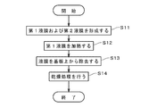
- FIG. 2 is a diagram showing a processing flow of the substrate 9 in the substrate processing apparatus 1 shown in FIG.
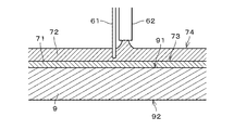
- FIG. 3 is an enlarged cross-sectional view showing a state near the upper surface 91 of the substrate 9.
- the substrate 9 is carried into the housing 11 and held by the substrate holding unit 31.
- the substrate 9 starts rotating at a low speed (for example, about 10 rpm) by the substrate rotating mechanism 33.
- the first processing liquid is supplied from the first nozzle 61 onto the upper surface 91 of the substrate 9 under the control of the supply control unit 63 of the processing liquid supply unit 6.
- the first processing liquid discharged from the first nozzle 61 to the central portion of the upper surface 91 of the substrate 9 spreads radially outward on the upper surface 91 of the substrate 9.
- a first liquid film 71 that is a liquid film of the first processing liquid is formed on the upper surface 91 of the substrate 9.
- the first liquid film 71 covers the entire upper surface 91 of the substrate 9.
- the first processing liquid that has reached the outer edge of the substrate 9 falls from the outer edge to the cup portion 4 and is collected or discarded.
- the supply of the first processing liquid from the first nozzle 61 is stopped.
- the second liquid is supplied from the second nozzle 62 onto the upper surface 91 of the substrate 9 under the control of the supply control unit 63 (see FIG. 1). Since the second processing liquid discharged from the second nozzle 62 to the central portion of the upper surface 91 of the substrate 9 has a specific gravity smaller than that of the first processing liquid, the second processing liquid is radially outward on the upper surface 73 of the first liquid film 71. spread. Thereby, a second liquid film 72 that is a liquid film of the second processing liquid is formed on the upper surface 73 of the first liquid film 71 (step S11). In other words, in step S ⁇ b> 11, the processing liquid supply unit 6 forms the first liquid film 71 and the second liquid film 72 that covers the upper surface 73 of the first liquid film 71 on the upper surface 73 of the substrate 9. .
- the second liquid film 72 covers the entire upper surface 73 of the first liquid film 71. That is, the upper surface 73 of the first liquid film 71 is also the lower surface of the second liquid film 72 and is an interface between the first liquid film 71 and the second liquid film 72.
- the tip of the first nozzle 61 is located between the upper surface 91 of the substrate 9 and the upper surface 74 of the second liquid film 72 with the second liquid film 72 formed.
- the second processing liquid that has reached the outer edge of the substrate 9 falls from the outer edge to the cup portion 4 and is collected or discarded. Even after the second liquid film 72 is formed, the supply of the second processing liquid from the second nozzle 62 is not stopped, and the second processing liquid is continuously supplied from the processing liquid supply unit 6 to the second liquid film 72. Is done.
- the substrate 9 is heated from the lower surface 92 side by the heating unit 5 (see FIG. 1).
- substrate 9 is heated from the lower surface 92 side of the board
- the first liquid film 71 is heated at a temperature equal to or higher than the boiling point of the first processing liquid and lower than the boiling point of the second processing liquid (hereinafter referred to as “liquid film heating temperature”).
- the liquid film heating temperature is, for example, about 80 degrees.
- the first processing liquid By heating the first liquid film 71 at the liquid film heating temperature, the first processing liquid is vaporized (that is, boiled) in the first liquid film 71 between the second liquid film 72 and the substrate 9. ) On the substrate 9, the second liquid film 72 in contact with the upper surface 73 of the first liquid film 71 is also heated. However, as described above, the liquid film heating temperature is lower than the boiling point of the second processing liquid. The second processing liquid does not vaporize (that is, boil) in the film 72.
- FIG. 4 and 5 are cross-sectional views showing a further enlarged portion near the upper surface 91 of the substrate 9 shown in FIG.
- the bubbles 711 of the first processing liquid vaporized between the second liquid film 72 and the substrate 9 move upward in the first liquid film 71 by buoyancy.
- the bubbles 711 adhere to the foreign matter 95 attached on the upper surface 91 of the substrate 9, and the foreign matter 95 is separated from the upper surface 91 of the substrate 9 by buoyancy acting on the bubbles 711.
- the foreign matter 95 peeled from the substrate 9 moves upward in the first liquid film 71 together with the bubbles 711 of the first processing liquid, and passes through the upper surface 73 of the first liquid film 71 as shown in FIG. It moves into the two liquid film 72.
- the foreign matter 95 that has moved into the second liquid film 72 is held by the second liquid film 72. Further, the bubbles 711 of the first processing liquid that have moved into the second liquid film 72 move from the upper surface 74 of the second liquid film 72 to the outside of the second liquid film 72.
- the second processing liquid is continuously supplied from the processing liquid supply unit 6 to the second liquid film 72 in parallel with the vaporization of the first processing liquid in step S12. Therefore, the foreign matter 95 held in the second liquid film 72 moves outward in the radial direction together with the second processing liquid and is removed from the substrate 9.
- the foreign liquid 95 is removed from the upper surface 91 of the substrate 9 by heating the first liquid film 71 for a predetermined time.
- the heating of the first liquid film 71 is stopped.
- the first liquid film 71 whose volume is reduced by vaporization preferably remains in a state of covering the entire upper surface 91 of the substrate 9. For this reason, it is possible to prevent the second liquid film 72 holding the foreign matter 95 from coming into contact with the upper surface 91 of the substrate 9. As a result, the foreign matter 95 in the second liquid film 72 can be prevented from reattaching to the upper surface 91 of the substrate 9.
- the rotation of the substrate 9 is started by the substrate rotating mechanism 33 (see FIG. 1) while the supply of the second processing liquid onto the substrate 9 is continued.
- the first liquid film 71 and the second liquid film 72 on the substrate 9 move outward in the radial direction, scatter from the outer edge of the substrate 9 to the surroundings, and the upper surface 91 of the substrate 9. It is removed from the top (step S13).
- the second processing liquid supplied from the second nozzle 62 onto the upper surface 91 of the substrate 9 also spreads outward in the radial direction and scatters from the outer edge of the substrate 9 to the surroundings.
- the first processing liquid and the second processing liquid splashed from the substrate 9 are received by the cup unit 4 and discharged to the outside of the cup unit 4 and the housing 11 through the discharge port.
- the cleaning process is performed on the upper surface 91 of the substrate 9 by supplying the second processing liquid and rotating the substrate 9 for a predetermined time.
- the predetermined time elapses, the cleaning process for the substrate 9 ends.
- step S14 the process of step S14 is referred to as “drying process”.
- drying process the process of step S14 is also discharged to the outside of the cup unit 4 and the housing 11 through the discharge port.
- the substrate 9 that has been dried is carried out of the housing 11.
- the above-described steps S11 to S14 are sequentially performed on the plurality of substrates 9.
- the first processing liquid and the second processing liquid having a lower specific gravity and a higher boiling point than the first processing liquid are supplied onto the upper surface 91 of the substrate 9.
- a first liquid film 71 that is a liquid film of the liquid and a second liquid film 72 that is a liquid film of the second processing liquid that covers the upper surface 73 of the first liquid film 71 are formed on the upper surface 91 of the substrate 9.
- the first liquid film 71 is heated at a temperature equal to or higher than the boiling point of the first processing liquid and lower than the boiling point of the second processing liquid.
- the foreign matter 95 on the upper surface 91 of the substrate 9 is peeled from the upper surface 91 by the first treatment liquid vaporized between the second liquid film 72 and the substrate 9 and moved into the second liquid film 72.
- the substrate processing apparatus 1 is particularly suitable for removing the foreign matter 95 from the upper surface 91 of the substrate 9 on which a pattern is formed in advance.
- the upper surface 73 of the first liquid film 71 is covered with the second liquid film 72 having a boiling point higher than the liquid film heating temperature. Even if it disappears by vaporization, there is no possibility that the upper surface 91 of the substrate 9 is exposed. Therefore, since it is not necessary to control the heating of the first liquid film 71 with high accuracy, the foreign matter 95 from the substrate 9 can be easily removed.
- the heating unit 5 heats the substrate 9 from the lower surface 92 side, whereby the first liquid film 71 is heated in step S12. As a result, an upward flow of the first processing liquid is generated in the first liquid film 71. As a result, the foreign matter 95 is easily peeled upward from the upper surface 91 of the substrate 9, so that the foreign matter 95 can be more suitably removed from the substrate 9. Further, the foreign matter 95 peeled from the upper surface 91 of the substrate 9 can be easily moved to the second liquid film 72 located above the first liquid film 71.
- the second processing liquid is continuously applied to the second liquid film 72 in parallel with the vaporization of the first processing liquid and the movement of the foreign matter 95 to the second liquid film 72 in Step S ⁇ b> 12.
- the foreign matter 95 peeled off from the substrate 9 and held in the second liquid film 72 is quickly moved radially outward together with the second processing liquid, and in parallel with the heating of the first liquid film 71. And can be quickly removed from the substrate 9.
- the first processing liquid may be continuously supplied to the first liquid film 71 in parallel with step S12. Accordingly, it is possible to prevent the first liquid film 71 from being completely vaporized and disappeared during the heating of the first liquid film 71 for a predetermined time. In this case, since the tip of the first nozzle 61 in the state where the second liquid film 72 is formed is located between the upper surface 91 of the substrate 9 and the upper surface 74 of the second liquid film 72, The first processing liquid can be easily supplied to the covered first liquid film 71.
- the second liquid film 72 is removed from the upper surface 91 of the substrate 9 by rotating the substrate 9. It is removed (step S13). Thereby, the second liquid film 72 holding the foreign matter 95 can be easily removed from the substrate 9, and the cleaning process of the substrate 9 can be easily completed.
- the first liquid film 71 covers the entire upper surface 91 of the substrate 9, and the second liquid film 72 covers the entire upper surface 73 of the first liquid film 71.
- substrate 9 can be wash
- a two-liquid film 72 may be formed. Then, by heating the first liquid film 71 to the liquid film heating temperature, the foreign matter 95 is removed from the upper surface 91 in the same manner as described above in the portion on the upper surface 91 of the substrate 9 that is desired to be cleaned.
- the formation of the first liquid film 71 and the second liquid film 72 in step S11 may be performed while rotating the substrate 9 at a relatively low speed by the substrate rotation mechanism 33.
- the first processing liquid on the substrate 9 and the second processing liquid on the first liquid film 71 are rapidly spread radially outward.
- the time required for forming the first liquid film 71 and the second liquid film 72 can be shortened.
- the heating of the first liquid film 71 in step S12 may also be performed while rotating the substrate 9 at a relatively low speed. Thereby, the whole 1st liquid film 71 can be heated substantially equally.
- step S11 the supply of the second processing liquid may be started before the first liquid film 71 covers the entire upper surface 91 of the substrate 9.
- the first treatment liquid spreads more quickly on the upper surface 91 of the substrate 9 than the second treatment liquid, and the second treatment liquid The entire upper surface 91 of the substrate 9 is covered before the processing liquid. Thereby, the time required for forming the first liquid film 71 and the second liquid film 72 on the substrate 9 can be shortened.
- the second liquid film 72 may be formed before the first processing liquid is supplied onto the substrate 9.
- the tip of the first nozzle 61 is in contact with the upper surface 91 of the substrate 9 in a state where the second liquid film 72 is formed, that is, in a state before the supply of the first processing liquid. It is located between the upper surface 74 of the second liquid film 72. Therefore, the first processing liquid discharged from the first nozzle 61 easily passes through the second liquid film 72 and reaches the upper surface 91 of the substrate 9, and radially outward along the upper surface 91 of the substrate 9. spread. As a result, even if the first processing liquid is supplied after the second liquid film 72 is formed, the first liquid film 71 is easily formed between the substrate 9 and the second liquid film 72. can do.
- the supply of the first treatment liquid and the supply of the second treatment liquid are started simultaneously, and the formation of the first liquid film 71 and the formation of the second liquid film 72 are performed in parallel. Also good. Thereby, formation of the 1st liquid film 71 and the 2nd liquid film 72 can be completed in a short time. Also in this case, since the tip of the first nozzle 61 in the state where the second liquid film 72 is formed is located between the upper surface 91 of the substrate 9 and the upper surface 74 of the second liquid film 72, The first liquid film 71 can be easily formed between the liquid film 72 and the liquid film 72.
- either the first liquid film 71 or the second liquid film 72 may be formed first or in parallel in step S ⁇ b> 11.
- the tip of the first nozzle 61 is positioned between the upper surface 91 of the substrate 9 and the upper surface 74 of the second liquid film 72 in a state where the second liquid film 72 is formed. Regardless of the order in which the first liquid film 71 and the second liquid film 72 are formed, the first liquid film 71 and the second liquid film 72 can be easily formed.
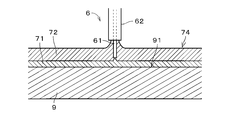
- FIG. 6 is a view showing another preferred structure of the processing liquid supply unit 6.
- the first nozzle 61 and the second nozzle 62 are double nozzles. Specifically, the first nozzle 61 is disposed in the flow path of the second nozzle 62, and the second processing liquid is discharged along the first nozzle 61 from the periphery of the first nozzle 61. Also in the example shown in FIG. 6, the first nozzle 61 and the second nozzle 62 are disposed above the central portion of the substrate 9, and the tip of the first nozzle 61 is located below the tip of the second nozzle 62. In the substrate processing apparatus 1, even when the first nozzle 61 and the second nozzle 62 shown in FIG.
- the tip of the first nozzle 61 is placed on the substrate 9 with the second liquid film 72 formed. It is located between the upper surface 91 and the upper surface 74 of the second liquid film 72. Accordingly, the first liquid film 71 and the second liquid film 72 can be easily formed regardless of the order in which the first liquid film 71 and the second liquid film 72 are formed.
- the supply of the first treatment liquid from the first nozzle 61 and the supply of the second treatment liquid from the second nozzle 62 are performed in parallel, and the first liquid film 71 and the second liquid film are performed. The case where 72 is formed in parallel is shown.
- FIG. 7 is a diagram showing another preferred treatment liquid supply unit.
- the first nozzle 61 and the second nozzle 62 are double nozzles, and the tip of the first nozzle 61 and the tip of the second nozzle 62 are at approximately the same position in the vertical direction.
- step S11 the discharge of the first processing liquid and the discharge of the second processing liquid are started simultaneously, thereby forming the first liquid film 71 on the upper surface 91 of the substrate 9, and The formation of the second liquid film 72 on the upper surface 73 of the first liquid film 71 is performed in parallel. Thereby, formation of the 1st liquid film 71 and the 2nd liquid film 72 can be completed in a short time.
- the first nozzle 61 is disposed in the flow path of the second nozzle 62, and the second processing liquid is discharged along the first nozzle 61 from the periphery of the first nozzle 61. Therefore, the first processing liquid discharged from the first nozzle 61 can easily reach the upper surface 91 of the substrate 9 without being inhibited by the second processing liquid. As a result, the first liquid film 71 can be easily formed.
- the discharge of the second processing liquid may be started after the first liquid film 71 is formed first.
- FIG. 8 is a diagram showing a configuration of a substrate processing apparatus 1a according to the second embodiment of the present invention.
- the substrate processing apparatus 1a is substantially the same as the substrate processing apparatus 1 shown in FIG. 1 except that the processing liquid supply unit 6b includes one nozzle 60 instead of the first nozzle 61 and the second nozzle 62 in FIG. It has a structure.
- the processing liquid supply unit 6b includes one nozzle 60 instead of the first nozzle 61 and the second nozzle 62 in FIG. It has a structure.
- configurations corresponding to the configurations of the substrate processing apparatus 1 are denoted by the same reference numerals.
- the nozzle 60 is connected to a first processing liquid supply source 65 and a second processing liquid supply source 67.
- the nozzle 60 selectively discharges the first processing liquid or the second processing liquid toward the center portion of the upper surface 91 of the substrate 9.
- the first processing liquid is supplied from the nozzle 60 to the upper surface 91 of the substrate 9, and the first liquid film 71 (see FIG. 3) is formed on the upper surface 91 of the substrate 9. ) Is formed. Subsequently, the discharge of the first processing liquid from the nozzle 60 is stopped, and the discharge of the second processing liquid is started. Then, the second processing liquid is supplied from the nozzle 60 to the upper surface 73 of the first liquid film 71, and the second liquid film 72 is formed on the upper surface 73 of the first liquid film 71 (FIG. 2: step S11).
- the substrate 9 is not rotated by the substrate rotation mechanism 33. Alternatively, the first liquid film 71 and the second liquid film 72 are sequentially formed in a state where the substrate 9 is rotated at a relatively low speed.
- step S12 the first liquid film 71 is heated at a liquid film heating temperature that is equal to or higher than the boiling point of the first processing liquid and lower than the boiling point of the second processing liquid. Then, the foreign matter 95 (see FIGS. 4 and 5) on the upper surface 91 of the substrate 9 is peeled off from the upper surface 91 by the first treatment liquid vaporized between the second liquid film 72 and the substrate 9, and the second It is moved into the liquid film 72. Thereby, similarly to the above, the foreign matter 95 can be suitably removed from the substrate 9 while suppressing damage to the upper surface 91 of the substrate 9.
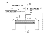
- FIG. 9 is a diagram showing a configuration of a substrate processing apparatus 1b according to the third embodiment of the present invention.
- the substrate processing apparatus 1b has the substrate processing apparatus shown in FIG. 1 except that the heating unit 5 below the substrate 9 is omitted and a processing liquid heating unit 663 for heating the second processing liquid is provided in the processing liquid supply unit 6c. 1 has approximately the same structure.
- configurations corresponding to the configurations of the substrate processing apparatus 1 are denoted by the same reference numerals.
- the first liquid film 71 (see FIG. 3) is formed on the upper surface 91 of the substrate 9 in the same manner as the substrate processing apparatus 1 in step S11. Thereafter, the second processing liquid heated by the processing liquid heating unit 663 is supplied from the second nozzle 62 onto the upper surface 73 of the first liquid film 71 on the substrate 9.
- the treatment liquid heating unit 663 the second treatment liquid is heated to a temperature higher than the above-described liquid film heating temperature (which is naturally higher than the boiling point of the first treatment liquid) and lower than the boiling point of the second treatment liquid. Heated.
- the heating of the first liquid film 71 by the second liquid film 72 heated by the processing liquid heating unit 663 is performed.
- the first liquid film 71 is heated to the liquid film heating temperature.
- the foreign matter 95 (see FIGS. 4 and 5) on the upper surface 91 of the substrate 9 is peeled from the upper surface 91 by the first treatment liquid vaporized between the second liquid film 72 and the substrate 9, and the second liquid It is moved to the film 72 (step S12).
- the foreign matter 95 can be suitably removed from the substrate 9 while suppressing damage to the upper surface 91 of the substrate 9.
- the substrate processing apparatus 1b since it is not necessary to provide a heating unit for heating the substrate 9 from the lower surface 92 side in or near the substrate holding unit 31, the structure of the substrate holding unit 31 or the vicinity of the substrate holding unit 31 is simplified. Can be
- step S11 the supply of the second processing liquid is started before the first liquid film 71 covers the entire upper surface 91 of the substrate 9. May be.
- step S ⁇ b> 11 the second liquid film 72 may be formed before the first processing liquid is supplied onto the substrate 9.
- step S11 the supply of the first treatment liquid and the supply of the second treatment liquid may be started at the same time, and the formation of the first liquid film 71 and the formation of the second liquid film 72 may be performed in parallel. .
- the first liquid film 71 may be heated between the substrate 9 and the second liquid film 72 until the first liquid film 71 is vaporized and disappears.
- the heating unit 5 may be a light irradiation unit arranged above the substrate holding unit 31.
- the second liquid film 72 is irradiated with light from the heating unit 5, whereby the first liquid film 71 is heated to the liquid film heating temperature via the second liquid film 72.
- the heating unit 5 may be a gas supply unit that is disposed above the substrate holding unit 31 and supplies a gas (for example, an inert gas) heated by the second liquid film 72.
- the first liquid film 71 is heated to the liquid film heating temperature via the second liquid film 72 by the heated gas from the heating unit 5.
- a heating unit 5 for heating the first liquid film 71 from the lower surface 92 side of the substrate 9 may be provided. Thereby, the 1st liquid film 71 can be heated rapidly.
- the first processing liquid and the second processing liquid are supplied onto the substrate 9 without being mixed, but the mixed liquid of the first processing liquid and the second processing liquid is the substrate 9. It may be supplied above.
- the first processing liquid sinks onto the upper surface 91 of the substrate 9 due to the difference in specific gravity and separates from the second processing liquid.
- a second liquid film 72 is formed.
- the mixed liquid for example, a liquid obtained by removing foreign substances with a filter or the like from the mixed liquid of the first processing liquid and the second processing liquid collected and used for the foreign substance removal processing of the other substrate 9 is used.
- another processing liquid different from the first processing liquid and the second processing liquid is formed on the upper surface 74 of the second liquid film 72 or between the second liquid film 72 and the first liquid film 71.
- the liquid film may be formed.
- FIG. 10 is a diagram showing the configuration of another preferred substrate processing apparatus 1c.
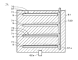
- the substrate processing apparatus 1c is a batch-type apparatus that performs a foreign substance removal process substantially similar to the above on a plurality of substrates 9 in parallel.
- the substrate processing apparatus 1c includes a storage tank 81, a first nozzle 61a, and a second nozzle 62a.
- the second nozzle 62 a supplies the second processing liquid (for example, pure water or IPA) from the bottom of the storage tank 81 into the storage tank 81.
- the second processing liquid from the second nozzle 62 a is stored in the storage tank 81.
- the plurality of substrates 9 are each held by a holding unit (not shown) with the upper surface 91 facing upward, and are immersed in the second processing liquid 720 in the storage tank 81.
- the first nozzle 61a is disposed on the side of the plurality of substrates 9, and discharges a first processing liquid (for example, HFE) from the plurality of discharge ports toward the upper side of the upper surfaces 91 of the plurality of substrates 9. Since the first processing liquid discharged above the upper surface 91 of each substrate 9 has a higher specific gravity than the second processing liquid 720, the first processing liquid sinks in the second processing liquid 720 and spreads on the upper surface 91 of each substrate 9. . Thereby, the first liquid film 71 covering the entire upper surface 91 of each substrate 9 is formed.
- a first processing liquid for example, HFE
- a first liquid film 71 covering the entire upper surface 91 of the substrate 9 is formed on each substrate 9, and the first liquid film 71 is formed on the first liquid film 71.
- a second liquid film is formed to cover the entire upper surface 73.
- the first liquid film 71 on each substrate 9 is heated to the above-described liquid film heating temperature. Then, the foreign substance on the upper surface 91 of the substrate 9 is peeled off from the upper surface 91 by the first processing liquid vaporized between the second liquid film and each substrate 9, and the second liquid film (that is, the second processing) In the liquid 720) and held by the second treatment liquid 720. Thereby, similarly to the above, foreign matter can be suitably removed from the substrate 9 while suppressing damage to the upper surface 91 of the substrate 9.
- the heating of the first liquid film 71 may be performed by, for example, a heater provided in the above-described holding unit that holds the plurality of substrates 9, or may be performed by irradiating each substrate 9 with light.
- the second treatment liquid 720 may be heated so that the temperature of the second treatment liquid 720 in the storage tank 81 is higher than the liquid film heating temperature.
- the second processing liquid is further supplied from the second nozzle 62 a into the storage tank 81, so that the second processing liquid holding foreign matter overflows from the upper end of the storage tank 81 and is discarded.
- the first processing liquid and the second processing liquid may be variously changed.
- the first treatment liquid is a carbon tetrachloride, chloroform, dichloromethane, 1,2-dichloroethane, carbon disulfide, which has a lower specific gravity and lower boiling point than pure water, It may be 1,1,1-trichloroethane.
- the above-described substrate processing apparatuses 1, 1a to 1c may be used for processing glass substrates used in display devices such as liquid crystal display devices, plasma displays, and FED (field display) in addition to semiconductor substrates.
- the substrate processing apparatuses 1, 1a to 1c may be used for processing of an optical disk substrate, a magnetic disk substrate, a magneto-optical disk substrate, a photomask substrate, a ceramic substrate, a solar cell substrate, and the like.
- the substrate 9 is rotated at a low speed in the stage of forming the first liquid film and the second liquid film in step S11. However, the substrate 9 may be stopped at this stage.
Landscapes
- Cleaning Or Drying Semiconductors (AREA)
- Exposure Of Semiconductors, Excluding Electron Or Ion Beam Exposure (AREA)
Abstract
Description
5 加熱部
6,6a~6c 処理液供給部
9 基板
31 基板保持部
33 基板回転機構
61,61a 第1ノズル
62,62a 第2ノズル
71 第1液膜
72 第2液膜
73 (第1液膜の)上面
91 (基板の)上面
92 (基板の)下面
95 異物
J1 中心軸
S11~S14 ステップ
Claims (19)
- 基板を処理する基板処理装置であって、
水平状態に基板を保持する基板保持部と、
前記基板の上面上に第1処理液および前記第1処理液よりも比重が小さく沸点が高い第2処理液を供給し、前記第1処理液の液膜である第1液膜、および、前記第1液膜の上面を覆う前記第2処理液の液膜である第2液膜を前記基板の前記上面上に形成する処理液供給部と、
を備え、
前記第1処理液の沸点以上かつ前記第2処理液の沸点よりも低い温度にて前記第1液膜の加熱が行われることにより、前記第2液膜と前記基板との間にて気化した前記第1処理液により、前記基板の前記上面上の異物を前記基板の前記上面から剥離させて前記第2液膜内へと移動させる。 - 請求項1に記載の基板処理装置であって、
上下方向を向く中心軸を中心として前記基板を前記基板保持部と共に回転させることにより、前記第2液膜を前記基板の前記上面上から除去する基板回転機構をさらに備える。 - 請求項1または2に記載の基板処理装置であって、
前記第1処理液の気化と並行して、前記処理液供給部から前記第2液膜に前記第2処理液が継続的に供給される。 - 請求項1ないし3のいずれかに記載の基板処理装置であって、
前記第1処理液の気化と並行して、前記処理液供給部から前記第1液膜に前記第1処理液が継続的に供給される。 - 請求項1ないし4のいずれかに記載の基板処理装置であって、
前記基板を下面側から加熱することにより前記第1液膜の前記加熱を行う加熱部をさらに備える。 - 請求項1ないし5のいずれかに記載の基板処理装置であって、
前記第1処理液の沸点よりも高くかつ前記第2処理液の沸点よりも低い温度にて前記処理液供給部から前記基板上に供給された前記第2処理液により、前記第1液膜の前記加熱が行われる。 - 請求項1ないし6のいずれかに記載の基板処理装置であって、
前記処理液供給部が、
前記第1処理液を前記基板の前記上面に向けて吐出する第1ノズルと、
前記第2処理液を前記基板の前記上面に向けて吐出する第2ノズルと、
を備え、
前記第2液膜が形成された状態で、前記第1ノズルの先端が、前記基板の前記上面と前記第2液膜の上面との間に位置する。 - 請求項1ないし7のいずれかに記載の基板処理装置であって、
前記第1液膜が前記基板の前記上面全体を覆い、
前記第2液膜が前記第1液膜の前記上面全体を覆う。 - 請求項1ないし8のいずれかに記載の基板処理装置であって、
前記第1処理液がハイドロフルオロエーテルであり、前記第2処理液が純水である。 - 請求項1ないし8のいずれかに記載の基板処理装置であって、
前記第1処理液がハイドロフルオロエーテルであり、前記第2処理液がイソプロピルアルコールである。 - 基板を処理する基板処理方法であって、
a)水平状態に保持された基板の上面上に第1処理液および前記第1処理液よりも比重が小さく沸点が高い第2処理液を供給し、前記第1処理液の液膜である第1液膜、および、前記第1液膜の上面を覆う前記第2処理液の液膜である第2液膜を前記基板の前記上面上に形成する工程と、
b)前記第1処理液の沸点以上かつ前記第2処理液の沸点よりも低い温度にて前記第1液膜の加熱を行うことにより、前記第2液膜と前記基板との間にて気化した前記第1処理液により、前記基板の前記上面上の異物を前記基板の前記上面から剥離させて前記第2液膜内へと移動させる工程と、
を備える。 - 請求項11に記載の基板処理方法であって、
前記b)工程よりも後に、上下方向を向く中心軸を中心として前記基板を回転させることにより、前記第2液膜を前記基板の前記上面上から除去する工程をさらに備える。 - 請求項11または12に記載の基板処理方法であって、
前記b)工程と並行して、前記第2液膜に前記第2処理液が継続的に供給される。 - 請求項11ないし13のいずれかに記載の基板処理方法であって、
前記b)工程と並行して、前記第1液膜に前記第1処理液が継続的に供給される。 - 請求項11ないし14のいずれかに記載の基板処理方法であって、
前記b)工程において、前記基板を下面側から加熱することにより前記第1液膜の前記加熱が行われる。 - 請求項11ないし15のいずれかに記載の基板処理方法であって、
前記第1処理液の沸点よりも高くかつ前記第2処理液の沸点よりも低い温度にて前記基板上に供給された前記第2処理液により、前記b)工程における前記第1液膜の前記加熱が行われる。 - 請求項11ないし16のいずれかに記載の基板処理方法であって、
前記第1液膜が前記基板の前記上面全体を覆い、
前記第2液膜が前記第1液膜の前記上面全体を覆う。 - 請求項11ないし17のいずれかに記載の基板処理方法であって、
前記第1処理液がハイドロフルオロエーテルであり、前記第2処理液が純水である。 - 請求項11ないし17のいずれかに記載の基板処理方法であって、
前記第1処理液がハイドロフルオロエーテルであり、前記第2処理液がイソプロピルアルコールである。
Priority Applications (3)
| Application Number | Priority Date | Filing Date | Title |
|---|---|---|---|
| KR1020177025399A KR101976968B1 (ko) | 2015-03-27 | 2016-03-16 | 기판 처리 장치 및 기판 처리 방법 |
| CN201680014580.7A CN107408502B (zh) | 2015-03-27 | 2016-03-16 | 基板处理装置和基板处理方法 |
| US15/558,042 US10549322B2 (en) | 2015-03-27 | 2016-03-16 | Substrate processing apparatus and substrate processing method |
Applications Claiming Priority (2)
| Application Number | Priority Date | Filing Date | Title |
|---|---|---|---|
| JP2015-065995 | 2015-03-27 | ||
| JP2015065995A JP6453688B2 (ja) | 2015-03-27 | 2015-03-27 | 基板処理装置および基板処理方法 |
Publications (1)
| Publication Number | Publication Date |
|---|---|
| WO2016158410A1 true WO2016158410A1 (ja) | 2016-10-06 |
Family
ID=57004483
Family Applications (1)
| Application Number | Title | Priority Date | Filing Date |
|---|---|---|---|
| PCT/JP2016/058288 Ceased WO2016158410A1 (ja) | 2015-03-27 | 2016-03-16 | 基板処理装置および基板処理方法 |
Country Status (6)
| Country | Link |
|---|---|
| US (1) | US10549322B2 (ja) |
| JP (1) | JP6453688B2 (ja) |
| KR (1) | KR101976968B1 (ja) |
| CN (1) | CN107408502B (ja) |
| TW (1) | TWI644343B (ja) |
| WO (1) | WO2016158410A1 (ja) |
Families Citing this family (10)
| Publication number | Priority date | Publication date | Assignee | Title |
|---|---|---|---|---|
| KR102570382B1 (ko) * | 2017-12-07 | 2023-08-25 | 도쿄엘렉트론가부시키가이샤 | 기판 처리 장치, 기판 처리 방법 및 기판 처리 방법을 실행시키는 프로그램이 기록된 기억 매체 |
| JP7016265B2 (ja) * | 2018-01-11 | 2022-02-04 | 株式会社Screenホールディングス | 基板処理方法及び基板処理装置 |
| JP7045196B2 (ja) * | 2018-01-15 | 2022-03-31 | 東京応化工業株式会社 | 基板処理装置及び基板処理方法 |
| JP7175118B2 (ja) * | 2018-07-25 | 2022-11-18 | 東京エレクトロン株式会社 | 基板処理装置、および基板処理方法 |
| JP7265874B2 (ja) | 2019-01-28 | 2023-04-27 | 株式会社Screenホールディングス | 基板処理方法および基板処理装置 |
| TWI691358B (zh) * | 2019-03-04 | 2020-04-21 | 日商長瀨過濾器股份有限公司 | 過濾器洗淨方法及過濾器洗淨裝置 |
| JP7301662B2 (ja) * | 2019-07-29 | 2023-07-03 | 株式会社Screenホールディングス | 基板処理方法および基板処理装置 |
| JP7427475B2 (ja) * | 2020-02-28 | 2024-02-05 | 株式会社Screenホールディングス | 基板処理方法 |
| CN113448173B (zh) * | 2020-05-25 | 2022-03-01 | 重庆康佳光电技术研究院有限公司 | 一种涂布方法和涂布系统 |
| US11550223B2 (en) | 2020-05-25 | 2023-01-10 | Chongqing Konka Photoelectric Technology Research Institute Co., Ltd. | Coating method and coating system |
Citations (3)
| Publication number | Priority date | Publication date | Assignee | Title |
|---|---|---|---|---|
| JP2001246337A (ja) * | 2000-03-09 | 2001-09-11 | Mitsubishi Electric Corp | 微細孔を有する部品の湿式表面処理方法 |
| JP2006181426A (ja) * | 2004-12-27 | 2006-07-13 | Dainippon Screen Mfg Co Ltd | 基板処理装置および基板処理方法 |
| JP2011077144A (ja) * | 2009-09-29 | 2011-04-14 | Dainippon Screen Mfg Co Ltd | 基板処理装置および基板処理方法 |
Family Cites Families (16)
| Publication number | Priority date | Publication date | Assignee | Title |
|---|---|---|---|---|
| JP3892749B2 (ja) * | 2002-03-29 | 2007-03-14 | 大日本スクリーン製造株式会社 | 基板処理装置および基板処理方法 |
| JP4767767B2 (ja) * | 2006-06-19 | 2011-09-07 | 大日本スクリーン製造株式会社 | 基板処理方法および基板処理装置 |
| KR20080008614A (ko) | 2006-07-20 | 2008-01-24 | 황진찬 | 숙성 전체 인삼 조성물, 숙성 인삼 몸통 조성물, 숙성 미삼조성물 및 숙성 복합 인삼 조성물 및 그 각각의 제조방법. |
| JP4960075B2 (ja) * | 2006-12-18 | 2012-06-27 | 大日本スクリーン製造株式会社 | 基板処理方法および基板処理装置 |
| JP4886544B2 (ja) | 2007-02-09 | 2012-02-29 | 大日本スクリーン製造株式会社 | 基板処理方法および基板処理装置 |
| JP4803821B2 (ja) | 2007-03-23 | 2011-10-26 | 大日本スクリーン製造株式会社 | 基板処理装置 |
| JP4994990B2 (ja) * | 2007-08-03 | 2012-08-08 | 東京エレクトロン株式会社 | 基板処理方法、基板処理装置、プログラム、記録媒体および置換剤 |
| JP5413016B2 (ja) | 2008-07-31 | 2014-02-12 | 東京エレクトロン株式会社 | 基板の洗浄方法、基板の洗浄装置及び記憶媒体 |
| JP5385628B2 (ja) | 2009-02-13 | 2014-01-08 | 大日本スクリーン製造株式会社 | 基板処理方法および基板処理装置 |
| JP5234985B2 (ja) | 2009-03-31 | 2013-07-10 | 大日本スクリーン製造株式会社 | 基板処理装置及び基板処理方法 |
| JP2011121009A (ja) | 2009-12-11 | 2011-06-23 | Dainippon Screen Mfg Co Ltd | 基板処理装置および基板処理方法 |
| JP5254308B2 (ja) | 2010-12-27 | 2013-08-07 | 東京エレクトロン株式会社 | 液処理装置、液処理方法及びその液処理方法を実行させるためのプログラムを記録した記録媒体 |
| TWI480937B (zh) | 2011-01-06 | 2015-04-11 | 斯克林集團公司 | 基板處理方法及基板處理裝置 |
| US20120260947A1 (en) | 2011-04-12 | 2012-10-18 | Satoshi Kaneko | Substrate cleaning apparatus, substrate cleaning method, and computer-readable recording medium having substrate cleaning program recorded therein |
| JP6080291B2 (ja) | 2012-09-28 | 2017-02-15 | 株式会社Screenホールディングス | 基板処理方法および基板処理装置 |
| JP6131162B2 (ja) * | 2012-11-08 | 2017-05-17 | 株式会社Screenホールディングス | 基板処理方法および基板処理装置 |
-
2015
- 2015-03-27 JP JP2015065995A patent/JP6453688B2/ja active Active
-
2016
- 2016-03-16 CN CN201680014580.7A patent/CN107408502B/zh active Active
- 2016-03-16 US US15/558,042 patent/US10549322B2/en active Active
- 2016-03-16 WO PCT/JP2016/058288 patent/WO2016158410A1/ja not_active Ceased
- 2016-03-16 KR KR1020177025399A patent/KR101976968B1/ko active Active
- 2016-03-23 TW TW105108989A patent/TWI644343B/zh active
Patent Citations (3)
| Publication number | Priority date | Publication date | Assignee | Title |
|---|---|---|---|---|
| JP2001246337A (ja) * | 2000-03-09 | 2001-09-11 | Mitsubishi Electric Corp | 微細孔を有する部品の湿式表面処理方法 |
| JP2006181426A (ja) * | 2004-12-27 | 2006-07-13 | Dainippon Screen Mfg Co Ltd | 基板処理装置および基板処理方法 |
| JP2011077144A (ja) * | 2009-09-29 | 2011-04-14 | Dainippon Screen Mfg Co Ltd | 基板処理装置および基板処理方法 |
Also Published As
| Publication number | Publication date |
|---|---|
| CN107408502A (zh) | 2017-11-28 |
| US10549322B2 (en) | 2020-02-04 |
| CN107408502B (zh) | 2020-10-16 |
| JP6453688B2 (ja) | 2019-01-16 |
| KR101976968B1 (ko) | 2019-05-09 |
| TWI644343B (zh) | 2018-12-11 |
| JP2016186971A (ja) | 2016-10-27 |
| KR20170116120A (ko) | 2017-10-18 |
| US20180068876A1 (en) | 2018-03-08 |
| TW201707059A (zh) | 2017-02-16 |
Similar Documents
| Publication | Publication Date | Title |
|---|---|---|
| JP6453688B2 (ja) | 基板処理装置および基板処理方法 | |
| TWI698906B (zh) | 基板處理方法以及基板處理裝置 | |
| JP4870837B2 (ja) | 基板乾燥装置及びその方法 | |
| JP5889691B2 (ja) | 基板処理装置および基板処理方法 | |
| TWI646596B (zh) | 基板處理方法以及基板處理裝置 | |
| TWI547765B (zh) | 基板處理方法及基板處理裝置 | |
| JP6811619B2 (ja) | 基板処理方法および基板処理装置 | |
| JP5926086B2 (ja) | 基板処理装置および基板処理方法 | |
| TWI740095B (zh) | 基板處理方法及基板處理裝置 | |
| JP2009212301A (ja) | 基板処理方法および基板処理装置 | |
| JP2010027816A (ja) | 基板処理方法および基板処理装置 | |
| TWI721495B (zh) | 基板處理裝置、處理液以及基板處理方法 | |
| JP6449097B2 (ja) | 基板処理方法及び基板処理装置並びに基板処理プログラムを記憶したコンピュータ読み取り可能な記憶媒体 | |
| TWI672738B (zh) | 基板處理方法及基板處理裝置 | |
| JP2009021409A (ja) | 凍結処理装置、凍結処理方法および基板処理装置 | |
| JP2022178469A (ja) | 基板処理方法および基板処理装置 | |
| JP2009224692A (ja) | 基板処理装置および基板処理方法 | |
| JP5208586B2 (ja) | 基板処理方法 | |
| WO2020105376A1 (ja) | 基板処理方法および基板処理装置 | |
| JP2008034428A (ja) | 基板処理装置および基板処理方法 | |
| JP6529798B2 (ja) | 基板処理装置および基板処理方法 | |
| TW201913792A (zh) | 基板處理裝置以及基板處理方法 | |
| JP2022043845A (ja) | 液処理方法及び液処理装置 | |
| JP2014187253A (ja) | 基板処理装置および基板処理方法 | |
| JP2013021246A (ja) | 基板処理装置および基板処理方法 |
Legal Events
| Date | Code | Title | Description |
|---|---|---|---|
| 121 | Ep: the epo has been informed by wipo that ep was designated in this application |
Ref document number: 16772293 Country of ref document: EP Kind code of ref document: A1 |
|
| ENP | Entry into the national phase |
Ref document number: 20177025399 Country of ref document: KR Kind code of ref document: A |
|
| WWE | Wipo information: entry into national phase |
Ref document number: 15558042 Country of ref document: US |
|
| NENP | Non-entry into the national phase |
Ref country code: DE |
|
| 122 | Ep: pct application non-entry in european phase |
Ref document number: 16772293 Country of ref document: EP Kind code of ref document: A1 |