WO2016158223A1 - 運転支援装置及び運転支援方法 - Google Patents
運転支援装置及び運転支援方法 Download PDFInfo
- Publication number
- WO2016158223A1 WO2016158223A1 PCT/JP2016/057013 JP2016057013W WO2016158223A1 WO 2016158223 A1 WO2016158223 A1 WO 2016158223A1 JP 2016057013 W JP2016057013 W JP 2016057013W WO 2016158223 A1 WO2016158223 A1 WO 2016158223A1
- Authority
- WO
- WIPO (PCT)
- Prior art keywords
- target
- timing
- collision avoidance
- host vehicle
- safety device
- Prior art date
Links
- 238000000034 method Methods 0.000 title claims description 163
- 238000012545 processing Methods 0.000 claims abstract description 91
- 230000008569 process Effects 0.000 claims description 158
- 230000003111 delayed effect Effects 0.000 claims description 11
- 230000001133 acceleration Effects 0.000 claims description 3
- 238000012937 correction Methods 0.000 description 147
- 230000006870 function Effects 0.000 description 31
- 238000001514 detection method Methods 0.000 description 24
- 230000004044 response Effects 0.000 description 17
- 230000004048 modification Effects 0.000 description 15
- 238000012986 modification Methods 0.000 description 15
- 238000003384 imaging method Methods 0.000 description 12
- 238000010586 diagram Methods 0.000 description 11
- 230000000694 effects Effects 0.000 description 9
- 230000033228 biological regulation Effects 0.000 description 6
- 230000007423 decrease Effects 0.000 description 6
- 230000004927 fusion Effects 0.000 description 6
- 230000008859 change Effects 0.000 description 5
- 238000013459 approach Methods 0.000 description 4
- 238000000605 extraction Methods 0.000 description 4
- 230000007257 malfunction Effects 0.000 description 4
- 230000003247 decreasing effect Effects 0.000 description 2
- 238000005516 engineering process Methods 0.000 description 2
- 239000000284 extract Substances 0.000 description 2
- 230000005540 biological transmission Effects 0.000 description 1
- 230000000994 depressogenic effect Effects 0.000 description 1
- 230000012447 hatching Effects 0.000 description 1
- 230000007246 mechanism Effects 0.000 description 1
- 230000000116 mitigating effect Effects 0.000 description 1
Images


Classifications
-
- B—PERFORMING OPERATIONS; TRANSPORTING
- B60—VEHICLES IN GENERAL
- B60W—CONJOINT CONTROL OF VEHICLE SUB-UNITS OF DIFFERENT TYPE OR DIFFERENT FUNCTION; CONTROL SYSTEMS SPECIALLY ADAPTED FOR HYBRID VEHICLES; ROAD VEHICLE DRIVE CONTROL SYSTEMS FOR PURPOSES NOT RELATED TO THE CONTROL OF A PARTICULAR SUB-UNIT
- B60W30/00—Purposes of road vehicle drive control systems not related to the control of a particular sub-unit, e.g. of systems using conjoint control of vehicle sub-units
- B60W30/08—Active safety systems predicting or avoiding probable or impending collision or attempting to minimise its consequences
- B60W30/09—Taking automatic action to avoid collision, e.g. braking and steering
-
- B—PERFORMING OPERATIONS; TRANSPORTING
- B60—VEHICLES IN GENERAL
- B60R—VEHICLES, VEHICLE FITTINGS, OR VEHICLE PARTS, NOT OTHERWISE PROVIDED FOR
- B60R21/00—Arrangements or fittings on vehicles for protecting or preventing injuries to occupants or pedestrians in case of accidents or other traffic risks
-
- B—PERFORMING OPERATIONS; TRANSPORTING
- B60—VEHICLES IN GENERAL
- B60W—CONJOINT CONTROL OF VEHICLE SUB-UNITS OF DIFFERENT TYPE OR DIFFERENT FUNCTION; CONTROL SYSTEMS SPECIALLY ADAPTED FOR HYBRID VEHICLES; ROAD VEHICLE DRIVE CONTROL SYSTEMS FOR PURPOSES NOT RELATED TO THE CONTROL OF A PARTICULAR SUB-UNIT
- B60W10/00—Conjoint control of vehicle sub-units of different type or different function
- B60W10/04—Conjoint control of vehicle sub-units of different type or different function including control of propulsion units
-
- B—PERFORMING OPERATIONS; TRANSPORTING
- B60—VEHICLES IN GENERAL
- B60W—CONJOINT CONTROL OF VEHICLE SUB-UNITS OF DIFFERENT TYPE OR DIFFERENT FUNCTION; CONTROL SYSTEMS SPECIALLY ADAPTED FOR HYBRID VEHICLES; ROAD VEHICLE DRIVE CONTROL SYSTEMS FOR PURPOSES NOT RELATED TO THE CONTROL OF A PARTICULAR SUB-UNIT
- B60W10/00—Conjoint control of vehicle sub-units of different type or different function
- B60W10/18—Conjoint control of vehicle sub-units of different type or different function including control of braking systems
-
- B—PERFORMING OPERATIONS; TRANSPORTING
- B60—VEHICLES IN GENERAL
- B60W—CONJOINT CONTROL OF VEHICLE SUB-UNITS OF DIFFERENT TYPE OR DIFFERENT FUNCTION; CONTROL SYSTEMS SPECIALLY ADAPTED FOR HYBRID VEHICLES; ROAD VEHICLE DRIVE CONTROL SYSTEMS FOR PURPOSES NOT RELATED TO THE CONTROL OF A PARTICULAR SUB-UNIT
- B60W10/00—Conjoint control of vehicle sub-units of different type or different function
- B60W10/20—Conjoint control of vehicle sub-units of different type or different function including control of steering systems
-
- B—PERFORMING OPERATIONS; TRANSPORTING
- B62—LAND VEHICLES FOR TRAVELLING OTHERWISE THAN ON RAILS
- B62D—MOTOR VEHICLES; TRAILERS
- B62D15/00—Steering not otherwise provided for
- B62D15/02—Steering position indicators ; Steering position determination; Steering aids
- B62D15/025—Active steering aids, e.g. helping the driver by actively influencing the steering system after environment evaluation
- B62D15/0265—Automatic obstacle avoidance by steering
-
- G—PHYSICS
- G08—SIGNALLING
- G08G—TRAFFIC CONTROL SYSTEMS
- G08G1/00—Traffic control systems for road vehicles
- G08G1/16—Anti-collision systems
-
- G—PHYSICS
- G08—SIGNALLING
- G08G—TRAFFIC CONTROL SYSTEMS
- G08G1/00—Traffic control systems for road vehicles
- G08G1/16—Anti-collision systems
- G08G1/166—Anti-collision systems for active traffic, e.g. moving vehicles, pedestrians, bikes
-
- B—PERFORMING OPERATIONS; TRANSPORTING
- B60—VEHICLES IN GENERAL
- B60R—VEHICLES, VEHICLE FITTINGS, OR VEHICLE PARTS, NOT OTHERWISE PROVIDED FOR
- B60R21/00—Arrangements or fittings on vehicles for protecting or preventing injuries to occupants or pedestrians in case of accidents or other traffic risks
- B60R21/01—Electrical circuits for triggering passive safety arrangements, e.g. airbags, safety belt tighteners, in case of vehicle accidents or impending vehicle accidents
- B60R21/013—Electrical circuits for triggering passive safety arrangements, e.g. airbags, safety belt tighteners, in case of vehicle accidents or impending vehicle accidents including means for detecting collisions, impending collisions or roll-over
- B60R21/0134—Electrical circuits for triggering passive safety arrangements, e.g. airbags, safety belt tighteners, in case of vehicle accidents or impending vehicle accidents including means for detecting collisions, impending collisions or roll-over responsive to imminent contact with an obstacle, e.g. using radar systems
-
- B—PERFORMING OPERATIONS; TRANSPORTING
- B60—VEHICLES IN GENERAL
- B60W—CONJOINT CONTROL OF VEHICLE SUB-UNITS OF DIFFERENT TYPE OR DIFFERENT FUNCTION; CONTROL SYSTEMS SPECIALLY ADAPTED FOR HYBRID VEHICLES; ROAD VEHICLE DRIVE CONTROL SYSTEMS FOR PURPOSES NOT RELATED TO THE CONTROL OF A PARTICULAR SUB-UNIT
- B60W2540/00—Input parameters relating to occupants
- B60W2540/10—Accelerator pedal position
-
- B—PERFORMING OPERATIONS; TRANSPORTING
- B60—VEHICLES IN GENERAL
- B60W—CONJOINT CONTROL OF VEHICLE SUB-UNITS OF DIFFERENT TYPE OR DIFFERENT FUNCTION; CONTROL SYSTEMS SPECIALLY ADAPTED FOR HYBRID VEHICLES; ROAD VEHICLE DRIVE CONTROL SYSTEMS FOR PURPOSES NOT RELATED TO THE CONTROL OF A PARTICULAR SUB-UNIT
- B60W2540/00—Input parameters relating to occupants
- B60W2540/12—Brake pedal position
-
- B—PERFORMING OPERATIONS; TRANSPORTING
- B60—VEHICLES IN GENERAL
- B60W—CONJOINT CONTROL OF VEHICLE SUB-UNITS OF DIFFERENT TYPE OR DIFFERENT FUNCTION; CONTROL SYSTEMS SPECIALLY ADAPTED FOR HYBRID VEHICLES; ROAD VEHICLE DRIVE CONTROL SYSTEMS FOR PURPOSES NOT RELATED TO THE CONTROL OF A PARTICULAR SUB-UNIT
- B60W2540/00—Input parameters relating to occupants
- B60W2540/18—Steering angle
-
- B—PERFORMING OPERATIONS; TRANSPORTING
- B60—VEHICLES IN GENERAL
- B60W—CONJOINT CONTROL OF VEHICLE SUB-UNITS OF DIFFERENT TYPE OR DIFFERENT FUNCTION; CONTROL SYSTEMS SPECIALLY ADAPTED FOR HYBRID VEHICLES; ROAD VEHICLE DRIVE CONTROL SYSTEMS FOR PURPOSES NOT RELATED TO THE CONTROL OF A PARTICULAR SUB-UNIT
- B60W2554/00—Input parameters relating to objects
-
- B—PERFORMING OPERATIONS; TRANSPORTING
- B60—VEHICLES IN GENERAL
- B60W—CONJOINT CONTROL OF VEHICLE SUB-UNITS OF DIFFERENT TYPE OR DIFFERENT FUNCTION; CONTROL SYSTEMS SPECIALLY ADAPTED FOR HYBRID VEHICLES; ROAD VEHICLE DRIVE CONTROL SYSTEMS FOR PURPOSES NOT RELATED TO THE CONTROL OF A PARTICULAR SUB-UNIT
- B60W2710/00—Output or target parameters relating to a particular sub-units
- B60W2710/18—Braking system
-
- B—PERFORMING OPERATIONS; TRANSPORTING
- B60—VEHICLES IN GENERAL
- B60W—CONJOINT CONTROL OF VEHICLE SUB-UNITS OF DIFFERENT TYPE OR DIFFERENT FUNCTION; CONTROL SYSTEMS SPECIALLY ADAPTED FOR HYBRID VEHICLES; ROAD VEHICLE DRIVE CONTROL SYSTEMS FOR PURPOSES NOT RELATED TO THE CONTROL OF A PARTICULAR SUB-UNIT
- B60W2710/00—Output or target parameters relating to a particular sub-units
- B60W2710/20—Steering systems
Definitions
- the present disclosure relates to a driving support technology that activates a safety device provided in the host vehicle when the host vehicle may collide with a target positioned forward in the traveling direction of the host vehicle.
- PCS Pre-Crash Safety
- TTC Time to Collation
- Patent Document 1 There is a driving support apparatus described in Patent Document 1 as related to PCS.
- a risk level indicating the possibility of collision between the host vehicle and the target is set, and information is presented to the driver according to the set risk level.
- the driver may feel bothered by the PCS when the safety device is activated despite the driver's intention to avoid the collision.
- This disclosure is intended to provide a driving support technology that can appropriately set the operation timing of the safety device according to the driver's intention.
- the first driving support device reduces collision damage or avoidance of collision between the host vehicle and the target when the host vehicle may collide with a target existing around the host vehicle.
- a driving support device that operates a safety device for the vehicle, and when there is a target around the host vehicle, an operation determination unit that determines whether or not a collision avoidance operation has been started by the driver, and a collision avoidance operation
- a delay means for performing a delay process of the operation timing, the operation timing for operating the safety device when it is determined that the collision avoidance operation has not been started, Operation determining means for determining whether to activate the safety device based on the operation timing, and the delay means performs delay processing until a predetermined period elapses after the collision avoidance operation is started. To continue.
- the intention of the driver to avoid the collision is determined, and the operation timing of the safety device is delayed according to the driver's intention. Therefore, in the driving support device of the present disclosure, it is possible to suppress unnecessary operation of the safety device (a state in which the safety device is activated when it is not necessary to operate; hereinafter referred to as “unnecessary operation”). Further, in the above configuration, the delay processing of the operation timing of the safety device is ended after a predetermined period has elapsed since the start of the collision avoidance operation by the driver. Therefore, in the driving assistance device according to the present disclosure, it is possible to suppress the non-operation of the safety device (the state where the safety device does not operate when it should be operated).
- the second driving support device avoids collision damage or collision damage between the host vehicle and the target when the host vehicle may collide with a target existing around the host vehicle.
- the operation timing for operating the safety device is set to be slower than when the collision avoidance operation is not determined to be performed.
- the operation when the collision avoidance operation is continuously performed by the driver, the operation may be temporarily interrupted. In such a case, if the delay process of the operation timing of the safety device is terminated, there is a possibility that an unnecessary operation of the safety device may occur. Therefore, in the above configuration, when the collision avoidance operation is continuously performed by the driver, the delay processing is continued until a predetermined period elapses after the operation is completed. Thereby, in the driving assistance device of the present disclosure, it is possible to suppress unnecessary operation of the safety device even when the collision avoidance operation by the driver is temporarily interrupted. Further, in the above configuration, the delay processing of the operation timing of the safety device is ended after a predetermined period has elapsed since the collision avoidance operation by the driver has ended. Therefore, in the driving assistance device according to the present disclosure, it is possible to suppress the operation delay of the safety device when there is a possibility of a collision.
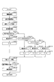
- FIG. 1 is a configuration diagram of a driving support device.
- FIG. 2 is a diagram illustrating a determination region in which the safety device is operated.
- FIG. 3 is a diagram illustrating a determination region when the operation timing delay process according to the first embodiment is performed.
- FIG. 4 is a flowchart showing processing according to the first embodiment.
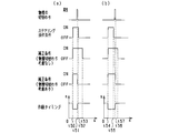
- FIG. 5 is a time chart when the process according to the first embodiment is performed.
- FIG. 6 is a flowchart showing processing according to the second embodiment.
- FIG. 7 is a time chart when the process according to the second embodiment is performed.
- FIG. 8 is a flowchart showing processing according to the third embodiment.
- FIG. 9 is a time chart when the processing according to the third embodiment is performed.
- FIG. 9 is a time chart when the processing according to the third embodiment is performed.
- FIG. 10 is a diagram illustrating a determination region when the operation timing delay process according to the fourth embodiment is performed.
- FIG. 11 is a diagram illustrating an example in which a plurality of targets are present.
- FIG. 12 is a flowchart illustrating processing according to the fifth embodiment.
- FIG. 13 is a time chart when the process according to the fifth embodiment is performed.
- FIG. 14 is a diagram for explaining the wrap rate.
- the driving assistance apparatus is mounted on a vehicle (own vehicle), detects a target existing around the front of the traveling direction of the own vehicle, and executes driving assistance processing (driving assistance method) described later. . Thereby, the driving assistance device performs control for avoiding the collision between the detected target and the host vehicle or reducing the collision damage.
- the driving assistance device functions as a PCS system.
- FIG. 1 is a configuration diagram of a driving support apparatus according to the present embodiment.
- a driving assistance ECU 10 that is a driving assistance device according to the present embodiment is a computer including a CPU, a memory (for example, ROM or RAM), an I / O, and the like.
- the driving assistance ECU 10 has functions of a target recognition unit 11, an operation state determination unit 12, an operation timing calculation unit 13, an operation determination unit 14, and a control processing unit 15.
- the CPU executes a program installed in, for example, a ROM to realize each function.
- the driving support ECU 10 is connected with a sensor device for inputting various detection information.
- sensor devices to be connected include a radar device 21, an imaging device 22, an accelerator sensor 23, a brake sensor 24, a steering sensor 25, and a vehicle speed sensor 26.
- the radar device 21 is, for example, a millimeter wave radar that transmits a high frequency signal in the millimeter wave band as a search wave.
- the radar device 21 is provided at the front end of the host vehicle.
- the radar device 21 detects a position of the target in the detectable region by setting a region extending over a range of a predetermined angle as a target detectable region.
- the radar device 21 transmits a survey wave at a predetermined control period and receives reflected waves by a plurality of antennas.
- the radar device 21 calculates the distance from the target that reflected the exploration wave based on the transmission time of the exploration wave and the reception time of the reflected wave. Further, the frequency of the reflected wave reflected by the target changes due to the Doppler effect.
- the radar device 21 calculates the relative velocity with respect to the target reflecting the exploration wave based on the frequency of the reflected wave that has changed. Furthermore, the radar apparatus 21 calculates the azimuth of the target reflecting the exploration wave based on the phase difference of the reflected wave received by the plurality of antennas. If the position and orientation of the target can be calculated, the relative position of the target with respect to the host vehicle can be specified. The radar device 21 transmits a search wave, receives a reflected wave, and calculates a relative position and a relative speed of a target with respect to the host vehicle at predetermined control periods. Then, the radar device 21 transmits the calculated relative position and relative speed per unit time to the driving support ECU 10.
- the imaging device 22 is, for example, a CCD camera, a CMOS image sensor, a near infrared camera, or the like.
- the imaging device 22 is provided at a predetermined height in the center in the vehicle width direction of the host vehicle.
- the imaging device 22 images a region that extends over a range of a predetermined angle toward the front of the vehicle from an overhead viewpoint.
- the imaging device 22 extracts a feature point indicating the presence of the target in the captured image. Specifically, the imaging device 22 extracts edge points based on the luminance information of the captured image, and performs Hough transform on the extracted edge points.
- the imaging device 22 performs imaging and feature point extraction for each control cycle that is the same as or different from that of the radar device 21. Then, the imaging device 22 transmits the feature point extraction result to the driving support ECU 10.
- Accelerator sensor 23 is provided on the accelerator pedal.
- the accelerator sensor 23 detects the presence or absence of the operation of the accelerator pedal by the driver and the operation amount (accelerator opening). Then, the accelerator sensor 23 transmits the presence / absence of the operation and the detection result of the operation amount to the driving support ECU 10 as operation information by the driver.
- the brake sensor 24 is provided on the brake pedal.
- the brake sensor 24 detects the presence / absence of an operation of the brake pedal by the driver and the operation amount (depression amount). Then, the brake sensor 24 transmits the presence / absence of the operation and the detection result of the operation amount to the driving support ECU 10 as operation information by the driver.
- the steering sensor 25 is provided in the steering.
- the steering sensor 25 detects the direction of the steering operation by the driver and the operation amount (steering angle). Then, the steering sensor 25 transmits the operation direction and the operation amount detection result to the driving support ECU 10 as operation information by the driver.
- the vehicle speed sensor 26 is provided on a rotating shaft that transmits power to the wheels of the host vehicle.
- the vehicle speed sensor 26 detects the speed of the host vehicle based on the number of rotations of the rotating shaft. Then, the vehicle speed sensor 26 transmits the speed detection result to the driving support ECU 10.
- the own vehicle includes an alarm device 31, a brake device 32, a seat belt device 33, and the like as various safety devices driven by a control command from the driving support ECU 10.
- the alarm device 31 is, for example, a speaker or a display installed in the passenger compartment of the host vehicle.
- the alarm device 31 outputs an alarm sound, an alarm message, or the like based on a control command from the driving support ECU 10 to cause a collision with the driver. Inform the danger.
- the brake device 32 is a braking device that brakes the host vehicle.
- the brake device 32 operates based on a control command from the driving support ECU 10. Specifically, the brake device 32 increases the braking force for the driver's braking operation, or performs automatic braking if the driver does not perform the braking operation. That is, the brake device 32 provides the driver with a brake assist function and an automatic brake function.
- the seat belt device 33 is a pretensioner (a mechanism provided for the purpose of improving the protection performance of the vehicle occupant) that pulls in the seat belt provided in each seat of the host vehicle.
- the seat belt device 33 performs a preliminary operation for retracting the seat belt based on a control command from the driving assistance ECU 10. Further, when the collision cannot be avoided, the seat belt device 33 pulls the seat belt to remove the slack. Accordingly, the seat belt device 33 fixes an occupant such as a driver to the seat and protects the vehicle occupant.
- the target recognition unit 11 acquires first detection information (position calculation result) from the radar device 21.
- the target recognition unit 11 acquires second detection information (extraction result of feature points) from the imaging device 22.
- the target recognition unit 11 uses the first position information indicated by the position obtained from the first detection information and the second position information indicated by the feature point obtained from the second detection information as follows. Associate with.
- the target recognition unit 11 associates information located in the vicinity as position information of the same target. When the position indicated by the second position information is present in the vicinity of the position indicated by the first position information, there is a high possibility that the target is actually present at the position indicated by the first position information.
- a state in which the radar device 21 and the imaging device 22 can acquire the position of the target with high accuracy is referred to as a “fusion state”.
- the target recognition unit 11 detects a target detection history (a past detection position) for a target determined to be in the fusion state (a target in which the first position information and the second position information are associated). To determine whether the target is continuously in the fusion state. As a result, the target recognizing unit 11 determines that the target is present at the position when it is determined that the fusion state is continued. Further, the target recognition unit 11 refers to the detection history of the target when the target that is continuously determined to be in the fusion state is in an undetected state, and the target is predetermined at the past detection position. What existed for a period of time.
- the target recognition unit 11 performs pattern matching on the target determined to be in the fusion state. Specifically, the target recognition unit 11 performs pattern matching on the second detection information using pattern data prepared in advance for each type of target that is assumed. Then, the target recognizing unit 11 determines whether the detected target is a vehicle or a pedestrian (passerby) based on the pattern matching result, and associates the determination result as the type of the target. In this embodiment, a person who rides a bicycle may be included in the concept of a pedestrian, which is one of the types of targets.
- the target recognition unit 11 associates the determined target with the relative position and relative speed with respect to the host vehicle. Then, the target recognizing unit 11 calculates a vertical speed that is a relative speed in the traveling direction of the host vehicle and a lateral speed that is a relative speed in a direction orthogonal to the traveling direction based on the relative position and the relative speed. calculate.
- the target recognizing unit 11 subdivides the type of the target based on the determination result of whether the vehicle is a pedestrian or the vertical speed and the horizontal speed.
- the vehicle type can be subdivided as follows.
- the target recognizing unit 11 distinguishes four types of vehicles based on the vertical speed and the horizontal speed. Specifically, a preceding vehicle that travels forward in the traveling direction of the host vehicle in the same direction as the host vehicle, and travels in a direction opposite to the host vehicle in the traveling direction forward of the host vehicle (runs in the opposite lane). Differentiate from oncoming vehicles. Further, a distinction is made between a stationary vehicle (stopped vehicle or parked vehicle) that stops in front of the traveling direction of the host vehicle and a passing vehicle that attempts to pass across the front of the traveling direction of the host vehicle.
- the pedestrian type can be subdivided as follows.
- the target recognition unit 11 distinguishes four types of pedestrians based on the vertical speed and the horizontal speed. Specifically, a distinction is made between a preceding pedestrian walking in the same direction as the host vehicle in the direction of travel of the host vehicle and an opposite pedestrian walking in the direction opposite to the host vehicle in the direction of travel of the host vehicle. To do. In addition, a distinction is made between a stationary pedestrian that stops in front of the traveling direction of the host vehicle and a crossing pedestrian that crosses the front of the traveling direction of the host vehicle.
- the target detected only by the first detection information can be subdivided as follows.
- the target recognition unit 11 distinguishes four types of targets based on the vertical speed and the horizontal speed. Specifically, a front target moving in the same direction as the host vehicle in the traveling direction ahead of the host vehicle and a counter target moving in the direction opposite to the host vehicle in the traveling direction forward of the host vehicle are distinguished. In addition, a distinction is made between a stationary target that stops in front of the traveling direction of the host vehicle and a passing target that attempts to pass across the front of the traveling direction of the host vehicle.
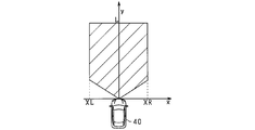
- FIG. 2 shows an x-axis indicating a horizontal position (horizontal position) orthogonal to the traveling direction of the host vehicle 40 and a vertical position (vertical position) that is the traveling direction. And a y-axis indicating.
- the operation determination unit 14 uses a predetermined determination region (a region indicated by hatching in the figure) as an operation condition for determining whether or not to operate the safety device in the forward direction of the host vehicle 40. Set to.
- the operation determination unit 14 functions as a region setting unit that sets an operation condition for operating the safety device.
- the operation determination unit 14 sets, for example, a determination region as illustrated in FIG. 2 based on the right restriction value XR, the left restriction value XL, and the front restriction value L (hereinafter referred to as “depth L”).
- depth L the front restriction value L
- the determination region has a predetermined lateral width based on the right restriction value XR in the right direction from the central axis of the host vehicle 40 toward the front in the traveling direction.
- the determination region has a predetermined lateral width based on the left limit value XL in the left direction toward the front in the traveling direction.
- the determination area has a predetermined vertical width (depth) based on the depth L in the vertical direction, which is the traveling direction.
- the right side regulation value XR and the left side regulation value XL are values determined in advance for each type of target. Therefore, the operation determination unit 14 sets the right restriction value XR and the left restriction value XL based on the type of the target. For example, when the target is a preceding vehicle, the operation determination unit 14 is less likely to make a sudden lateral movement, so the right restriction value XR and the left restriction value XL are set to be highly likely. Set smaller than the value.
- the operation determination unit 14 when the target is a pedestrian, the operation determination unit 14 has a high possibility of performing a rapid movement in the horizontal direction, and therefore, the right restriction value XR and the left restriction value XL are set to be less likely. Set larger than the value. In this way, the operation determination unit 14 sets the determination region for determining whether or not to operate the safety device based on the right restriction value XR, the left restriction value XL, and the depth L as the traveling direction of the host vehicle 40. Set forward.
- the operation status determination unit 12 determines whether or not a collision avoidance operation has been performed by the driver. Based on the operation information (detection results) from the accelerator sensor 23, the brake sensor 24, and the steering sensor 25, the operation state determination unit 12 determines whether or not the driver has performed a collision avoidance operation (willing to avoid collision with the driver). Whether or not there is). Further, the operation status determination unit 12 performs the above determination process when a target exists around the host vehicle 40 based on the recognition result (target detection result) from the target recognition unit 11. Thus, in the driving assistance ECU 10 according to the present embodiment, the operation state determination unit 12 functions as an operation determination unit. Next, the operation timing calculation unit 13 according to the present embodiment calculates the operation timing of the safety device.
- the operation timing calculation unit 13 corrects a preset initial value (hereinafter referred to as “reference timing”) and calculates a corrected operation timing (hereinafter referred to as “correction timing”). Specifically, the operation timing calculation unit 13, for example, detects information from the vehicle speed sensor 26 (speed detection result) and a recognition result from the target recognition unit 11 (the relative position of the target with respect to the host vehicle 40 and Based on (relative speed), a correction value (correction coefficient) of the operation timing is calculated. Then, the operation timing calculation unit 13 corrects the reference timing based on the calculated correction value, and calculates the correction timing.
- the operation timing calculation unit 13 determines that the calculation process (when the collision avoidance operation is started by the driver based on the determination result from the operation state determination unit 12 (the determination result of the collision avoidance operation)) ( Operation timing correction processing) is performed.
- the operation timing calculation unit 13 functions as an operation timing calculation unit.
- the safety device reference timing is preset for each safety device, such as the alarm device 31, the brake device 32, and the seat belt device 33, for example.
- the alarm device 31 has an operation timing that is earliest than other safety devices.
- the brake device 32 is set with operation timings for each of the brake assist function and the automatic brake function of the brake device 32. Note that these operation timings may be the same value or different values.
- the operation determination unit 14 determines the safety device based on the operation timing of the safety device calculated by the operation timing calculation unit 13 and the predicted collision time until the host vehicle 40 collides with the target. Determine whether to activate.
- the operation determination unit 14 calculates a collision prediction time until the host vehicle 40 collides with the target based on the vertical speed and the vertical position acquired from the target recognition unit 11.
- the operation determination unit 14 functions as a collision prediction unit. Note that relative acceleration may be used instead of the vertical velocity for calculating the collision prediction time.
- the depth L of the determination area is determined based on the operation timing of the safety device and the relative speed between the host vehicle 40 and the target.
- the operation determination unit 14 determines whether or not to operate the safety device based on the determination result of whether or not the operation timing has reached the predicted collision time (whether or not the target is within the determination region). As a result, the operation determination unit 14 determines that the safety device is to be operated when the operation timing has reached the predicted collision time (the target is within the determination region). On the other hand, the operation determination unit 14 determines that the safety device is not operated when the operation timing does not reach the collision prediction time (the target is outside the determination region).
- the operation determination unit 14 transmits a determination result (operation determination signal) to the control processing unit 15.
- the control processing unit 15 transmits a control signal to the safety device to be activated based on the received determination result. This activates the safety device.
- the operation determination unit 14 and the control processing unit 15 cooperate to function as an operation determination unit.
- the collision prediction time becomes the operation timing of the alarm device 31 first.
- the operation determination unit 14 transmits an operation determination signal of the alarm device 31 to the control processing unit 15.
- the control processing unit 15 transmits a control command signal to the alarm device 31 based on the received operation determination signal.
- the alarm device 31 is activated to notify the driver of the danger of collision.
- the operation determination unit 14 transmits an operation determination signal of the automatic brake function to the control processing unit 15.
- the control processing unit 15 transmits a control command signal to the brake device 32 and the seat belt device 33 based on the received operation determination signal.
- the automatic brake function of the brake device 32 is activated, and the braking of the host vehicle 40 is controlled.
- the seat belt device 33 is operated, and a preliminary operation for retracting the seat belt is performed.
- the predicted collision time becomes the operation timing of the brake assist function of the brake device 32.
- the operation determination unit 14 transmits an operation determination signal of the brake assist function to the control processing unit 15.
- the control processing unit 15 transmits a control command signal to the brake device 32 and the seat belt device 33 based on the received operation determination signal.
- the brake assist function of the brake device 32 is activated, and control is performed to increase the braking force with respect to the depression amount of the brake pedal by the driver.
- the seat belt device 33 is operated, and a preliminary operation for retracting the seat belt is performed.
- the operation timing calculation unit 13 performs a process of correcting the operation timing of the safety device and delaying the operation timing according to the correction timing (delay processing of the operation timing of the safety device). At this time, when the collision avoidance operation is performed by the driver, the operation timing calculation unit 13 performs a process of delaying the operation timing of the safety device compared to when the collision avoidance operation is not performed.
- the operation timing calculation unit 13 calculates a correction timing that is smaller than the reference timing value. For example, when 2.0 [seconds] is set as the reference timing, a process of calculating a correction timing of 1.7 [seconds] (a time shorter than the reference time) is performed.
- the operation timing calculation unit 13 transmits the calculated correction timing value to the operation determination unit 14.
- the operation determination unit 14 determines whether or not to operate the safety device based on the corrected operation timing. That is, the operation timing is a value that is compared with the predicted collision time when determining whether or not the safety device can be operated. In the determination of whether or not the safety device can be operated, it is determined that the safety device is activated when the operation timing reaches the predicted collision time. To do.
- the operation timing calculation unit 13 functions as a delay unit.
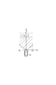
- FIG. 3 is a diagram illustrating a determination region when the delay process of the operation timing according to the present embodiment is performed.
- L_cor corrected depth
- the operation of the safety device is delayed when the collision avoidance operation is performed by the driver as compared with the case where the collision avoidance operation is not performed. And, for example, when the relative speed between the host vehicle 40 and the target decreases due to the collision avoidance operation by the driver, and the collision prediction time becomes longer, or when the target moves out of the determination area. The possibility that the own vehicle 40 will collide with the target is eliminated. Therefore, the safety device is not activated for such a target.
- the driving support ECU 10 does not perform delay processing of the operation timing when the safety device is already operating. For example, after the safety device is activated regardless of the driver's intention, the operation timing will be delayed if an operation intervention by the driver occurs. Therefore, in such a case, the delay process is not performed in order to prevent the operation of the safety device from being interrupted.
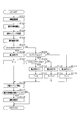
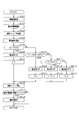
- FIG. 4 is a flowchart showing processing according to the present embodiment. Next, as described above, a series of processes (a series of processes performed by the driving support ECU 10) for determining whether or not to operate the safety device after delaying the operation timing will be described with reference to FIG. The process shown in FIG. 4 is executed for each target located in front of the traveling direction of the host vehicle 40 for each predetermined control cycle.
- the target recognition unit 11 performs target recognition processing (S101). At this time, the target recognizing unit 11 performs the recognition process based on the first detection information (position calculation result) from the radar device 21 and the second detection information (feature point extraction result) from the imaging device 22. . Subsequently, the driving assistance ECU 10 calculates the predicted collision time until the relative distance between the operation determination unit 14 and the subject vehicle 40 becomes zero for the recognized target (S102). At this time, the operation determination unit 14 performs the calculation process based on the vertical speed and the vertical position acquired from the target recognition unit 11. Subsequently, the driving assistance ECU 10 acquires the reference timing (initial value of the operation timing) for the operation timing calculation unit 13 to operate the safety device (S103).
- This reference timing is, for example, a value that is stored in a predetermined storage area of a memory provided in the driving support ECU 10 and is preset for each safety device. Therefore, the operation timing calculation unit 13 acquires the reference timing by reading the corresponding data from the memory. Subsequently, in the driving assistance ECU 10, the operation state determination unit 12 acquires the operation information of the accelerator pedal by the driver from the accelerator sensor 23 (S104). In addition, about this process after that, the case where the presence or absence of operation of an accelerator pedal and the detection result of the operation amount are acquired as operation information for collision avoidance by the driver will be described as an example for convenience. That is, in the present embodiment, processing based on an accelerator operation that is one of collision avoidance operations by the driver will be described.
- the operation status determination unit 12 determines whether or not a collision avoidance operation has been performed by the driver based on the acquired operation information. Specifically, the operation state determination unit 12 determines whether or not the driver's operation is an operation for turning the accelerator from ON to OFF (collision avoidance operation) from the operation information (S105). At this time, for example, the operation status determination unit 12 is acquired in the current control cycle (current processing) rather than the accelerator pedal operation amount (accelerator opening) acquired in the previous control cycle (previous main processing). An affirmative determination may be made when the operation amount is smaller. Further, for example, the operation status determination unit 12 may make an affirmative determination on the condition that the accelerator is in the ON state in the previous control cycle and the accelerator is in the OFF state in the current control cycle.
- the operation state determination unit 12 determines that the driver's operation is an operation for turning the accelerator from ON to OFF (when it is determined that the collision avoidance operation has been performed; S105: YES), the process of S106 is performed.
- Migrate to The operation status determination unit 12 turns ON the correction condition for the operation timing of the safety device (control value for whether to correct) (S106).
- the operation state determination unit 12 determines that the driver's operation is not an operation for turning the accelerator from ON to OFF (when it is determined that the collision avoidance operation is not performed; S105: NO), the process of S108 is performed.
- Migrate to The operation status determination unit 12 determines whether or not the value of the counter T is greater than zero and less than the upper limit value Tmax (0 ⁇ T ⁇ Tmax) (S108).
- cases where it is determined that the operation is not an operation of turning the accelerator from ON to OFF include, for example, a case where the accelerator is maintained in an ON / OFF state, or a case where the accelerator is turned from OFF to ON.
- the result of the determination process in S105 is affirmative determination in the previous control cycle, the value of the counter T is 1. Therefore, in this control cycle, the result of the determination process in S108 is affirmative.
- the process proceeds to S109.
- the operation status determination unit 12 determines from the operation information whether the driver's operation is an operation for turning the accelerator from OFF to ON (S109). At this time, for example, the operation state determination unit 12 may make an affirmative determination when the operation amount acquired in the current control cycle is larger than the operation amount acquired in the previous control cycle. Further, for example, the operation status determination unit 12 may make an affirmative determination on the condition that the accelerator is in an OFF state in the previous control cycle and the accelerator is in an ON state in the current control cycle. In the determination process of S109, it is determined whether or not the collision avoidance operation by the driver is interrupted and an operation that increases the possibility of collision is performed.
- the operation state determination unit 12 determines that the driver's operation is an operation for turning the accelerator from OFF to ON (when it is determined that an operation that increases the possibility of a collision has been performed; S109: YES). , The process proceeds to S110.
- the operation state determination unit 12 determines that the driver's operation is not an operation that turns the accelerator from OFF to ON (when it is determined that an operation that increases the possibility of collision is not performed; S109: NO).
- the process proceeds to S112.
- the operation status determination unit 12 sets the correction condition to ON (S112). Then, the operation status determination unit 12 counts up the value of the counter T (T ⁇ T + 1) (S113).
- the operation status determination unit 12 determines that the value of the counter T is zero or the value of the counter T is the upper limit value Tmax (S108: NO)
- the operation status determination unit 12 proceeds to the process of S114.
- the operation status determination unit 12 sets the correction condition to OFF (S114).
- the operation status determination unit 12 initializes the counter T (S115).
- the result of the determination process of S108 is negative determination, for example, when the process of S113 is executed over a predetermined period, when the process of S111 is executed in the previous control period, or There are cases where the process of S115 is executed continuously.
- the operation timing calculation unit 13 calculates the operation timing of the safety device based on the correction condition setting result (ON / OFF control value) (S116). At this time, when the correction condition is ON, the operation timing calculation unit 13 calculates the correction timing from the reference timing acquired in the process of S103, and calculates the calculated correction timing as the operation timing calculation result. Specifically, for example, the operation timing calculation unit 13 divides the reference timing by the correction value, and uses the division value as the correction timing calculation result. In addition, when the correction condition is OFF, the operation timing calculation unit 13 uses the reference timing as a calculation result of the operation timing.
- the driving support ECU 10 compares the value of the collision prediction time calculated by the operation determination unit 14 in the processing of S102 with the operation timing calculated by the operation timing calculation unit 13 to determine whether to activate the safety device. Is determined (S117). At this time, the operation determination unit 14 determines whether or not the predicted collision time is equal to or shorter than the operation timing (collision prediction time ⁇ operation timing), and determines whether or not to operate the safety device based on the determination result (comparison result). judge. As a result, when it is determined that the predicted collision time is equal to or shorter than the operation timing (S117: YES), the operation determination unit 14 determines that the predicted collision time has reached the operation timing, and proceeds to the process of S118.
- the operation determination unit 14 operates the safety device, executes the driving support function (S118), and ends the series of processes. At this time, the operation determination unit 14 transmits a determination result (operation determination signal) to the control processing unit 15, and the control processing unit 15 transmits a control signal to the safety device to be operated based on the received determination result. To do. This activates the safety device. On the other hand, when the operation determination unit 14 determines that the predicted collision time is longer than the operation timing (S117: NO), the operation determination unit 14 ends the series of processes as it is, assuming that the predicted collision time has not reached the operation timing.
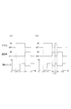
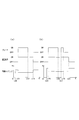
- FIG. 5 is a time chart when processing according to the present embodiment is performed. Next, the operation timing of the safety device at the time of executing the above process will be described with reference to FIG.
- FIG. 5 (a) shows an example in which the driver performs the operation of turning the accelerator from ON to OFF only once.
- the accelerator is turned on.
- the target is recognized in front of the traveling direction of the host vehicle 40, and the reference timing is set as the operation timing of the safety device.
- the driver turns off the accelerator.
- the operation timing correction condition is turned ON, and the operation timing becomes a correction timing having a value smaller than the reference timing.
- the operation timing correction condition is ON and the operation timing is set as the correction timing.
- the result of the determination process in S105 is negative, and the result of the determination process in S108 (determination whether the counter T is greater than zero and smaller than the upper limit value Tmax) is positive. It becomes a judgment.
- the result of the determination process in S109 determination as to whether or not the accelerator is turned from OFF to ON
- the value of the counter T becomes the upper limit value Tmax. Therefore, at t13, the result of the determination process in S108 is negative. As a result, the correction condition is turned off, and the operation timing is returned to the reference timing.
- FIG. 5 (b) shows an example in which the driver performs an operation to turn the accelerator from OFF to ON when the operation timing correction condition is satisfied.
- the accelerator is turned on.
- the target is recognized in front of the traveling direction of the host vehicle 40, and the reference timing is set as the operation timing of the safety device.
- the driver turns off the accelerator.
- the operation timing correction condition is turned ON, and the operation timing becomes a correction timing having a value smaller than the reference timing. This state (a process in which the operation timing correction condition is ON and the operation timing is the correction timing) is continued until t17.
- the driver turns on the accelerator again while the correction condition is satisfied.
- the operation timing correction condition is turned OFF, and processing for returning the operation timing to the reference timing is performed.
- the result of the determination process in S109 is affirmative.
- the driver turns off the accelerator again while the accelerator is kept on.
- the correction condition for the operation timing is turned ON again, and processing using the operation timing as the correction timing is performed.
- This state processing in which the operation timing correction condition is ON and the operation timing is the correction timing
- the value of the counter T becomes the upper limit value Tmax.
- the correction condition is turned off, and the operation timing is returned to the reference timing. Note that the length of the period from t12 to t13 shown in FIG. 5A is equal to the length of the period from t18 to t19 shown in FIG. 5B.
- the driving support device (driving support ECU 10) according to the present embodiment has the following effects due to the above configuration.
- the correction condition for the operation timing of the safety device is set (ON / OFF) based on a collision avoidance operation (for example, an operation for turning the accelerator from ON to OFF) by the driver. Yes. Therefore, the driving support device can determine the intention of the driver to avoid the collision and delay (change) the operation timing of the safety device according to the driver's intention. Thereby, in the driving assistance apparatus which concerns on this embodiment, the unnecessary operation
- the delay processing of the operation timing of the safety device is ended, and the operation timing is returned to the reference timing.
- the driving support device has the same overall configuration as the driving support device shown in the first embodiment, and is different in that the delay processing of the operation timing of the safety device is performed based on the brake operation. .
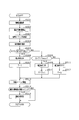
- FIG. 6 is a flowchart showing processing according to the present embodiment. A series of processes by the driving assistance ECU 10 according to the present embodiment will be described with reference to FIG. The process shown in FIG. 6 is executed for each target located in front of the traveling direction of the host vehicle 40 for each predetermined control cycle. In addition, about the subsequent this process, the content of 1st Embodiment is used for convenience and the description is simplified.
- the target recognition unit 11 performs a target recognition process (S201). Subsequently, the driving assistance ECU 10 calculates the predicted collision time until the relative distance between the operation determination unit 14 and the subject vehicle 40 becomes zero for the recognized target (S202). Subsequently, the driving assistance ECU 10 acquires the reference timing (initial value of the operation timing) for the operation timing calculation unit 13 to operate the safety device (S203). Subsequently, in the driving assistance ECU 10, the operation state determination unit 12 acquires the operation information of the brake pedal by the driver from the brake sensor 24 (S204).
- the operation status determination unit 12 determines whether or not a collision avoidance operation has been performed by the driver based on the acquired operation information. Specifically, the operation status determination unit 12 determines from the operation information whether the driver's operation is an operation for turning on the brake (collision avoidance operation) (S205). At this time, for example, the operation state determination unit 12 performs the brake operation based on the determination result of whether or not the operation amount (depression amount) of the brake pedal is equal to or greater than a threshold value (whether or not the depression amount exceeds a predetermined amount). It may be determined whether or not it has been broken. The operation status determination unit 12 may make an affirmative determination when the operation amount is equal to or greater than the threshold value.
- the operation state determination unit 12 proceeds to the process of S206. .
- the operation state determination unit 12 proceeds to the processing of S208. .
- the operation state determination unit 12 determines whether or not the driver's operation is an operation for turning the brake from ON to OFF from the operation information (S208). For example, when the result of the determination process in S205 is affirmative in the previous control cycle, the result of the determination process in S208 is affirmative. On the other hand, if the result of the determination process in S205 is negative in the previous control cycle, the result of the determination process in S208 is negative.
- the operation state determination unit 12 determines that the driver's operation is an operation for turning the brake from ON to OFF (when it is determined that the collision avoidance operation is interrupted; S208: YES), the process of S209 is performed.
- Migrate to The operation status determination unit 12 sets the correction condition to ON (S209).
- the process of S211 Migrate to The operation status determination unit 12 determines whether or not the value of the counter T is greater than zero and less than the upper limit value Tmax (0 ⁇ T ⁇ Tmax) (S211). For example, if the result of the determination process in S205 is affirmative in the previous control cycle, the value of the counter T is 1. Therefore, in this control cycle, the determination result in S211 is affirmative.
- the process proceeds to S212.
- the operation status determination unit 12 sets the correction condition to ON (S212). Then, the operation status determination unit 12 counts up the counter T (T ⁇ T + 1) (S213).
- the operation status determination unit 12 determines that the value of the counter T is zero or the value of the counter T is the upper limit value Tmax (S211: NO)
- the operation status determination unit 12 proceeds to the process of S214.
- the operation status determination unit 12 sets the correction condition to OFF (S214).
- the operation timing calculation unit 13 calculates the operation timing of the safety device based on the correction condition setting result (control value of ON / OFF) (S216). At this time, when the correction condition is ON, the operation timing calculation unit 13 calculates the correction timing from the reference timing acquired in the process of S203, and uses the calculated correction timing as a calculation result of the operation timing. In addition, when the correction condition is OFF, the operation timing calculation unit 13 uses the reference timing as a calculation result of the operation timing. Subsequently, the driving assistance ECU 10 compares the value of the collision prediction time calculated by the operation determination unit 14 in the process of S202 with the operation timing calculated by the operation timing calculation unit 13 to determine whether to activate the safety device. Is determined (S217).
- the operation determination unit 14 determines that the collision prediction time is equal to or less than the operation timing (S217: YES)
- the operation determination unit 14 proceeds to the process of S218, assuming that the collision prediction time has reached the operation timing.
- the operation determination unit 14 operates the safety device, executes the driving support function (S218), and ends the series of processes.
- the operation determination unit 14 transmits a determination result (operation determination signal) to the control processing unit 15, and the control processing unit 15 transmits a control signal to the safety device to be operated based on the received determination result. To do. This activates the safety device.
- the operation determination unit 14 determines that the predicted collision time is longer than the operation timing (S217: NO)
- the operation determination unit 14 ends the series of processes as it is, assuming that the predicted collision time has not reached the operation timing.
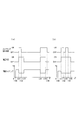
- FIG. 7 is a time chart when processing according to the present embodiment is performed. Next, the operation timing of the safety device at the time of executing the above process will be described with reference to FIG.
- FIG. 7 (a) shows an example in which the brake operation by the driver is finished without interruption.
- the target is recognized in front of the traveling direction of the host vehicle 40, and the reference timing is set as the operation timing of the safety device.
- the driver turns on the brake.
- the correction condition for the operation timing is turned ON, and the operation timing becomes a correction timing having a value smaller than the reference timing.
- the result of the determination process in S205 determination of whether or not the brake is turned on
- the positive result state of the determination process in S205 is continued until the brake is turned off.
- the driver turns off the brake.
- the result of the determination process of S205 is negative, and the result of the determination process of S208 (determination of whether or not the brake has been turned off) is affirmative. Therefore, at t22, the ON state of the correction condition is maintained. Thereafter, until t23, the operation timing correction condition is ON and the operation timing is set as the correction timing. In this period (period from t22 to t23), the result of the determination process in S205 is negative, and the result of the determination process in S208 is negative.
- the result of the determination process of S211 (determination of whether or not the counter T is greater than zero and smaller than the upper limit value Tmax) is an affirmative determination, and such a state continues.
- the value of the counter T becomes the upper limit value Tmax. Therefore, at t23, the result of the determination process in S211 is negative. As a result, the correction condition is turned off, and the operation timing is returned to the reference timing.
- FIG. 7B shows an example in which the brake operation by the driver is interrupted and the operation is started again after the operation is started again.
- a target is recognized in front of the traveling direction of the host vehicle 40, and a reference timing is set as an operation timing of the safety device.
- the driver turns on the brake at t25.
- the operation timing correction condition is turned ON, the operation timing becomes a correction timing having a value smaller than the reference timing, and this processing is continued.
- the driver turns off the brake. In response to this, at t26, the ON state of the correction condition is maintained, and then the counter T starts counting up.
- the driver turns on the brake again.
- the value of the counter T is less than the upper limit value Tmax.
- the result of the determination process in S205 is affirmative.
- the driver turns off the brake again.
- the count up of the counter T is started.
- the value of the counter T becomes the upper limit value Tmax. Therefore, at t29, the result of the determination process in S211 is negative. As a result, the correction condition is turned off, and the operation timing is returned to the reference timing.
- the length of the period from t22 to t23 shown in FIG. 7A is equal to the length of the period from t27 to t28 shown in FIG. 7B.
- the driving support device (driving support ECU 10) according to the present embodiment has the following effects in addition to the same effects as those of the first embodiment due to the above configuration.
- the brake pedal depression amount (operation amount) may temporarily decrease.
- the operation timing is set as the correction timing until a predetermined period elapses after the brake operation by the driver is completed. That is, in the driving support device, after a predetermined period has elapsed after the brake operation is finished, the delay processing of the operation timing of the safety device is ended, and the operation timing is returned to the reference timing.
- the driving assistance device it is possible to suppress unnecessary operation of the safety device even when the amount of depression of the brake pedal is temporarily reduced. Furthermore, in the driving support device according to the present embodiment, the operation timing is returned to the reference timing when the decrease in the brake pedal depression amount continues for a predetermined period. That is, in the driving support device, after a predetermined period has elapsed since the depression amount of the brake pedal has decreased, the delay processing of the operation timing of the safety device is terminated and the operation timing is returned to the reference timing. Thereby, in the driving assistance device concerning this embodiment, even if it is a case where the amount of depression of a brake pedal falls temporarily, the malfunction of a safety device can be controlled.
- the driving support device has the same overall configuration as the driving support device shown in the first embodiment, and is different in that the delay processing of the operation timing of the safety device is performed based on the steering operation. .
- FIG. 8 is a flowchart showing processing according to the present embodiment. A series of processes by the driving assistance ECU 10 according to the present embodiment will be described with reference to FIG. The process shown in FIG. 8 is executed for each target located in front of the traveling direction of the host vehicle 40 for each predetermined control cycle. In addition, about the subsequent this process, the content of 1st Embodiment is used for convenience and the description is simplified.
- the target recognition unit 11 performs a target recognition process (S301). Subsequently, the driving assistance ECU 10 calculates the collision prediction time until the relative distance between the operation determination unit 14 and the subject vehicle 40 becomes zero for the recognized target (S302). Subsequently, the driving assistance ECU 10 acquires the reference timing (initial value of the operation timing) at which the operation timing calculation unit 13 operates the safety device (S303). Subsequently, in the driving assistance ECU 10, the operation state determination unit 12 acquires the operation information of the steering by the driver from the steering sensor 25 (S304).
- the operation status determination unit 12 determines whether or not a collision avoidance operation has been performed by the driver based on the acquired operation information. Specifically, the operation status determination unit 12 determines from the operation information whether the steering operation (collision avoidance operation) condition (collision avoidance condition) has been changed from OFF to ON (whether the steering operation condition is satisfied). ) Is determined (S305). That is, the operation status determination unit 12 determines whether or not the collision between the host vehicle 40 and the target can be avoided by the steering operation in the determination process of S305. At this time, for example, the operation state determination unit 12 determines whether or not the operation amount (steering angle) acquired from the steering sensor 25 is greater than or equal to a threshold value (whether or not the steering angle exceeds a predetermined angle).
- the operation state determination unit 12 determines whether the steering operation direction at this time is the left or right direction.
- the operation state determination unit 12 determines the steering operation direction using the recognition result from the target recognition unit 11 (the position and relative speed of the target with respect to the host vehicle 40) and the like. For example, when the recognized target is located in front of the host vehicle 40 in the traveling direction and the target is moving in the left direction, the steering operation in the left direction and the right direction is performed. Suppose. In such a positional relationship and a moving relationship between the host vehicle 40 and the target, when a leftward steering operation is performed, it can be determined that the operation is not an operation for avoiding a collision with the target.
- a steering operation in the right direction it can be determined that the operation avoids a collision with the target. Further, it is assumed that the steering operation in the left direction and the right direction is performed when the target is located right in front of the traveling direction of the host vehicle 40 and the target is moving in the right direction. In such a positional relationship and moving relationship between the host vehicle 40 and the target, when a leftward steering operation is performed, it can be determined that the operation is to avoid a collision with the target. On the other hand, when the steering operation in the right direction is performed, it can be determined that the operation is not to avoid the collision with the target.
- the operation state determination unit 12 determines that the condition is ON and determines that the steering operation is not a collision with the target. In this case, it is determined that the condition is OFF. The same applies to the case where the target is located at the left front in the traveling direction of the host vehicle 40.
- the operation state determination unit 12 determines that the steering operation condition is changed from OFF to ON (when it is determined that the steering operation condition is satisfied; S305: YES)
- the operation state determination unit 12 proceeds to the process of S306.
- the process proceeds to S308.
- the operation status determination unit 12 determines whether or not the value of the counter T is greater than zero and less than the upper limit value Tmax (0 ⁇ T ⁇ Tmax) (S308).
- Tmax (0 ⁇ T ⁇ Tmax)
- it is determined that the steering operation condition is not ON from OFF for example, when the steering operation condition is maintained in the ON / OFF state, or the steering operation condition changes from ON to OFF.
- the determination result in S308 is affirmative.
- the process proceeds to S309.
- the operation status determination unit 12 sets the correction condition to ON (S309).
- the operation status determination unit 12 counts up the counter T (T ⁇ T + 1) (S310).
- the operation status determination unit 12 determines that the value of the counter T is zero or the value of the counter T is the upper limit value Tmax (S308: NO)
- the operation status determination unit 12 proceeds to the processing of S311.
- the operation status determination unit 12 sets the correction condition to OFF (S311).
- the operation timing calculation unit 13 calculates the operation timing of the safety device based on the correction condition setting result (ON / OFF control value) (S313). At this time, when the correction condition is ON, the operation timing calculation unit 13 calculates a correction timing from the reference timing acquired in the process of S303, and uses the calculated correction timing as a calculation result of the operation timing. In addition, when the correction condition is OFF, the operation timing calculation unit 13 uses the reference timing as a calculation result of the operation timing. Subsequently, the driving assistance ECU 10 compares the value of the collision prediction time calculated by the operation determination unit 14 in the processing of S302 with the operation timing calculated by the operation timing calculation unit 13 to determine whether to activate the safety device. Is determined (S314).
- the operation determination unit 14 determines that the collision prediction time is equal to or less than the operation timing (S314: YES)
- the operation determination unit 14 proceeds to the process of S315, assuming that the collision prediction time has reached the operation timing.
- the operation determination unit 14 operates the safety device, executes the driving support function (S315), and ends the series of processes.
- the operation determination unit 14 transmits a determination result (operation determination signal) to the control processing unit 15, and the control processing unit 15 transmits a control signal to the safety device to be operated based on the received determination result. To do. This activates the safety device.
- the operation determination unit 14 determines that the predicted collision time is longer than the operation timing (S314: NO)
- the operation determination unit 14 ends the series of processes as it is, assuming that the predicted collision time has not reached the operation timing.
- FIG. 9 is a time chart when processing according to the present embodiment is performed. Next, the operation timing of the safety device at the time of executing the above process will be described with reference to FIG.
- FIG. 9 (a) shows an example (part 1) in which the steering operation by the driver is finished once and then finished after the operation is started again.
- the target is recognized in front of the traveling direction of the host vehicle 40, and the reference timing is set as the operation timing of the safety device.
- the driver performs a steering operation.
- the correction condition of the operation timing is ON, and the operation timing is smaller than the reference timing. Correction timing.
- the result of the determination process in S305 (determination as to whether or not the steering operation condition has changed from OFF to ON) is affirmative.
- the affirmative result state (state in which the steering operation condition is satisfied) of the determination process in S305 is continued until the steering operation condition is turned off.
- the steering operation returns to the normal driving, but the ON condition of the correction condition is continued, the count up of the counter T is continued, and the operation timing remains at the correction timing. Thereafter, the value of the counter T becomes the upper limit value Tmax.
- the result of the determination process of S308 (determination as to whether the counter T is greater than zero and smaller than the upper limit value Tmax) is negative.
- the steering operation that satisfies the condition is performed again by the driver.
- the operation timing correction condition is turned ON, and the operation timing becomes the correction timing.
- the result of the determination process in S305 is affirmative.
- the restarted steering operation time (period from t34 to t36) is longer than the upper limit arrival time of the counter T (period from t34 to t35) (t35 ⁇ t36).
- the value of the counter T becomes the upper limit value Tmax before t36 when the steering operation ends (before the steering operation condition is turned off). Therefore, at t35 before t36, the result of the determination process in S308 is negative. As a result, the correction condition is turned off, and the operation timing is returned to the reference timing. That is, even if the steering operation is performed until t36, the process using the operation timing as the correction timing ends at t35 before t36 when the steering operation ends.
- FIG. 9 (b) shows an example (part 2) in which the steering operation by the driver is finished once and then finished after the operation is started again.
- the target is recognized in front of the traveling direction of the host vehicle 40, and the reference timing is set as the operation timing of the safety device.
- the driver performs a steering operation at t41.
- the correction condition of the operation timing is turned ON, and the operation timing becomes a correction timing having a value smaller than the reference timing.
- the result of the determination process in S305 is affirmative.
- the affirmative result state of the determination process of S305 is continued until the steering operation condition is turned off.
- the steering operation returns to the normal driving, but the ON condition of the correction condition is continued, the count up of the counter T is continued, and the operation timing remains at the correction timing.
- the driver performs a steering operation that satisfies the conditions again.
- the result of the determination process in S305 is affirmative.
- the length of the period from t31 to t33 shown in FIG. 9A is equal to the length of the period from t34 to t35, and the length of the period from t43 to t45 shown in FIG. 9B.
- the driving support device (driving support ECU 10) according to the present embodiment has the following effects due to the above configuration.
- the correction condition for the operation timing of the safety device is set (ON / OFF) based on the steering operation by the driver. Therefore, the driving support device can determine the intention of the driver to avoid the collision and delay (change) the operation timing of the safety device according to the driver's intention. Thereby, in the driving assistance apparatus which concerns on this embodiment, the unnecessary operation
- the delay processing of the operation timing of the safety device is ended, and the operation timing is returned to the reference timing.
- the operation timing is set as a reference while the steering operation condition (collision avoidance condition) is satisfied or until a predetermined period elapses after the condition is satisfied.
- the correction timing is smaller than the timing.
- the driving support apparatus has the same overall configuration as the driving support apparatus shown in the first embodiment. Further, in the driving support device according to the present embodiment, the delay processing of the operation timing of the safety device is common to the processing shown in the third embodiment. The driving support device according to the present embodiment is partially different in processing when setting a determination region for determining whether or not to operate the safety device.
- FIG. 10 is a diagram showing a determination region when the operation timing delay process according to the present embodiment is performed.
- the driving assistance ECU 10 acquires steering operation information (whether steering operation is performed) by the driver from the steering sensor 25 when setting the determination region.
- driving assistance ECU10 correct
- the right restriction value XR and the left restriction value XL that define the width of the determination region are respectively set to the right correction restriction value XR_cor and the left correction restriction value XL_cor that are smaller than the original restriction value.
- the driving assistance ECU 10 performs correction to narrow the width of the determination area when the driver performs a steering operation.
- the lateral width of the determination area is corrected by, for example, calculating the right correction restriction value XR_cor and the left correction restriction value XL_cor by subtracting the correction value from the restriction values of the right restriction value XR and the left restriction value XL. And based on the calculated regulation value after correction.
- the correction values of the right restriction value XR and the left restriction value XL may be values such that the correction amount increases as the operation amount of the steering operation increases, for example.
- the processing according to the present embodiment is the same as that of the third embodiment, and the operation timing of the safety device is set as the correction timing based on the steering operation. Therefore, in this embodiment, the vertical width of the determination area is also corrected. Specifically, the depth L (front restriction value) that defines the vertical width of the determination region is corrected so as to be a front correction restriction value L_cor that is smaller than the original restriction value. That is, when the driver performs a steering operation, the driving assistance ECU 10 performs correction to narrow the horizontal width and vertical width of the determination region.
- the driving support apparatus (driving support ECU 10) according to the present embodiment has the following effects in addition to the same effects as those of the third embodiment due to the above configuration.
- the driver tries to avoid a collision between the host vehicle 40 and the target only by a steering operation without performing an accelerator operation or a brake operation.
- the vertical relative position of the host vehicle 40 and the target (the vertical position of the target with respect to the host vehicle 40) is reduced with time, and the collision prediction time may reach the operation timing. is there. Further, at this time, the position of the target moves from the determination area to the left and right directions and changes away from the determination area by the driver's steering operation.
- the driving assistance device when the driver performs a steering operation, correction is performed to reduce the horizontal width and vertical width of the determination region.
- the driving support device corrects the right restriction value XR, the left restriction value XL, and the depth L (front restriction value) to be small, and the right correction restriction value XR_cor and the left correction restriction.
- a value XL_cor and a forward correction regulation value L_cor are obtained.
- the correction is made by setting the determination region using the right correction restriction value XR_cor, the left correction restriction value XL_cor, and the front correction restriction value L_cor.
- the driving support apparatus according to the present embodiment has the same overall configuration as the driving support apparatus shown in the first embodiment.
- the delay processing of the operation timing of the safety device is partially different from the processing shown in the third embodiment.
- FIG. 11 is a diagram illustrating an example in which a plurality of targets exist in front of the traveling direction of the host vehicle 40.
- the traveling direction of the host vehicle 40 is indicated by a broken line
- the traveling direction when the steering operation is performed is indicated by a solid line.
- FIG. 11 it is assumed that there are a plurality of targets of a first target 61 and a second target 62 in front of the traveling direction of the host vehicle 40. Further, at this time, it is assumed that the steering operation in the direction toward the second target 62 is performed in the host vehicle 40 and the collision with the first target 61 is avoided.
- the driving support ECU 10 is configured to switch the target of the delay processing of the operation timing of the safety device. That is, the driving assistance ECU 10 performs processing (hereinafter referred to as “collision avoidance target selection processing”) for selecting (changing) the target of the processing to delay the operation timing (collision avoidance target by the steering operation) based on the steering operation. .
- the selection process of the collision avoidance target is performed by the target recognition unit 11 included in the driving assistance ECU 10.
- the target recognition unit 11 performs a collision avoidance target selection process based on the positional relationship between the host vehicle 40 and the target.
- the target recognizing unit 11 may perform the object selection process on the condition of the following positional relationship.
- the target recognition unit 11 has a target whose horizontal position (relative position in the horizontal direction) with respect to the host vehicle 40 is closest to the central axis of the host vehicle 40 in the traveling direction among the plurality of targets. May be selected as a collision avoidance target by a steering operation.
- the target recognition unit 11 determines that the vertical position of the target with respect to the host vehicle 40 (the relative position in the vertical direction) in the traveling direction among the plurality of targets whose horizontal positions are within the width of the determination region. A target closest to the front end of the host vehicle 40 may be selected.
- the target recognizing unit 11 calculates a determination parameter by weighting each vertical and horizontal relative position (horizontal position and vertical position), and avoids a collision caused by a steering operation based on the calculated determination parameter. A target may be selected.
- the target recognition unit 11 selects a target for avoiding a collision by a steering operation from among a plurality of targets existing around the host vehicle 40. Functions as a means.
- FIG. 12 is a flowchart showing processing according to the present embodiment.
- a series of processes by the driving assistance ECU 10 according to the present embodiment will be described with reference to FIG.
- the process shown in FIG. 12 is executed for each target located in front of the traveling direction of the host vehicle 40 for each predetermined control cycle.
- the content of 3rd Embodiment is used for convenience and the description is simplified.
- the driving assistance ECU 10 performs processing equivalent to the processing of S301 to S304 shown in the third embodiment (S401 to S404).
- the driving assistance ECU 10 determines whether or not the target recognizing unit 11 has switched the collision avoidance target target due to the steering operation (S405).
- the target recognition unit 11 performs a collision avoidance target selection process based on the positional relationship between the host vehicle 40 and the target. Then, the target recognition unit 11 generates a collision avoidance target switching based on the determination result of whether or not the selected target is a target different from the previous control cycle (previous main process). Determine. As a result, when the target recognizing unit 11 determines that the collision avoidance target has been switched (S405: YES), the process proceeds to S406. At this time, the target recognizing unit 11 transmits the determination result to the operation state determining unit 12. In the driving assistance ECU 10, the operation state determination unit 12 turns OFF the correction condition of the operation timing of the safety device (control value for whether to correct) (S406).
- the target recognizing unit 11 determines that the collision avoidance target switching has not occurred (S405: NO)
- the target recognizing unit 11 performs processing equivalent to the processing of S305 to S312 shown in the third embodiment ( S408 to S415).
- the operation timing calculation unit 13 calculates the operation timing of the safety device based on the correction condition setting result (ON / OFF control value) (S416).
- the correction condition is ON
- the operation timing calculation unit 13 calculates the correction timing from the reference timing acquired in the process of S403, and uses the calculated correction timing as a calculation result of the operation timing.
- the correction condition is OFF
- the operation timing calculation unit 13 uses the reference timing as a calculation result of the operation timing.
- the driving assistance ECU 10 compares the value of the collision prediction time calculated by the operation determination unit 14 in the process of S402 and the operation timing calculated by the operation timing calculation unit 13 to determine whether to activate the safety device. Is determined (S417). As a result, when it is determined that the predicted collision time is equal to or shorter than the operation timing (S417: YES), the operation determination unit 14 determines that the predicted collision time has reached the operation timing, and proceeds to the process of S418. The operation determination unit 14 operates the safety device, executes the driving support function (S418), and ends the series of processes.
- the operation determination unit 14 transmits a determination result (operation determination signal) to the control processing unit 15, and the control processing unit 15 transmits a control signal to the safety device to be operated based on the received determination result. To do. This activates the safety device.
- the operation determination unit 14 determines that the predicted collision time is longer than the operation timing (S417: NO)
- the operation determination unit 14 ends the series of processes as it is, assuming that the predicted collision time has not reached the operation timing.
- FIG. 13 is a time chart when processing according to the present embodiment is performed. Next, the operation timing of the safety device at the time of executing the above process will be described with reference to FIG. In FIG. 13, the determination result of whether or not the steering operation condition (collision avoidance condition) is satisfied is the result of determining whether or not the condition for the first target 61 is satisfied under the situation shown in FIG. Is shown.
- the steering operation condition collision avoidance condition
- the driver performs a steering operation to avoid a collision with the first target 61.
- the operation timing correction condition is turned ON, and the operation timing becomes a correction timing having a value smaller than the reference timing.
- the result of the determination processing in S408 (determination as to whether or not the steering operation condition has changed from OFF to ON) is affirmative.
- the result of the determination processing in S405 determination of whether or not the collision avoidance target switching has occurred
- the change of the target is not taken into consideration, it is as follows.
- the steering operation condition is turned off.
- the value of the counter T becomes the upper limit value Tmax, the correction condition is turned OFF, and the operation timing is returned to the reference timing. That is, the process using the operation timing as the correction timing is continued until t53.
- the driver performs a steering operation.
- the correction condition of the operation timing is turned ON, and the operation timing becomes a correction timing having a value smaller than the reference timing.
- the result of the determination processing in S408 determination of whether or not the steering operation condition has changed from OFF to ON
- the steering operation condition is turned off. And when considering the switching of the target, it is as follows.
- the result of the determination processing in S405 determines whether or not the collision avoidance target switching has occurred
- the change of the target is not taken into consideration, it is as follows.
- the value of the counter T becomes the upper limit value Tmax, the correction condition is turned off, and the operation timing is returned to the reference timing. That is, the process using the operation timing as the correction timing is continued until t57.
- the driving support device (driving support ECU 10) according to the present embodiment has the following effects due to the above configuration.
- the traveling direction of the host vehicle 40 changes. Therefore, when there are a plurality of targets ahead of the traveling direction of the host vehicle 40, even if collision with any one of the plurality of targets can be avoided, the target 40 collides with other targets. there is a possibility. That is, when the operation timing of the safety device is delayed based on such a steering operation, there is a possibility that a delay (an operation delay of the safety device) may occur in the collision avoidance control with another target. Therefore, the driving assistance ECU 10 according to the present embodiment determines whether or not the collision avoidance target has been switched before determining whether or not the steering operation is to avoid the collision. When the driving assistance ECU 10 determines that the collision avoidance target has been switched, the operation timing of the safety device is used as the reference timing.
- the second target 62 exists in the direction of the steering operation. To do. Under such circumstances, if the operation timing of the safety device is delayed, the operation of the safety device with respect to the second target 62 may be delayed.
- the correction condition for the operation timing is turned OFF, and the operation timing is changed from the correction timing to the reference timing. return.
- the driving support apparatus according to the present embodiment has the same overall configuration as the driving support apparatus shown in the first embodiment.
- the delay processing of the operation timing of the safety device is partially different from the processing shown in the third embodiment.
- the present embodiment relates to processing for delaying the operation timing of the safety device when a preceding vehicle traveling in the same direction as the host vehicle 40 is ahead in the traveling direction of the host vehicle 40.
- the operation state determination unit 12 causes the vehicle widths of the host vehicle 40 and the preceding vehicle of the target to overlap based on detection information from the target recognition unit 11.
- the lap ratio La which is a value indicating the ratio to be performed, is calculated.
- the operation state determination unit 12 functions as a lap rate acquisition unit.
- FIG. 14 is a diagram for explaining the lap rate La.
- the lap rate La according to the present embodiment will be described with reference to FIG.
- the vehicle width of the host vehicle 40 is Xw
- the width of the region where the vehicle widths of the host vehicle 40 and the preceding vehicle of the target 60 overlap is X1.
- the operation state determination unit 12 calculates the lap rate La using the following equation (1).
- La Xl / Xw (1)
- the preceding vehicle of the target 60 increases as the lap rate La increases and the relative distance Ly decreases (the overlapping ratio of the vehicle width between the host vehicle 40 and the preceding vehicle of the target 60 increases).
- sudden braking or the like is performed in step 1
- the lap rate La is smaller and the relative distance Ly is longer (the smaller the overlap ratio of the vehicle width between the host vehicle 40 and the preceding vehicle of the target 60 is)
- sudden braking or the like is performed on the preceding vehicle of the target 60. In this case, it is easy to avoid a collision even if the steering angle is small.
- the operation state determination unit 12 changes the threshold for the steering angle, which is a determination condition for avoiding collision of the steering operation, based on the calculated lap rate La. Specifically, the operation state determination unit 12 decreases the threshold value because the smaller the lap rate La (or the smaller the lap rate La and the longer the relative distance Ly), the easier the collision can be avoided. On the other hand, the operation state determination unit 12 increases the threshold value because the larger the lap rate La (or the greater the lap rate La and the shorter the relative distance Ly), the more difficult it is to avoid a collision.
- the threshold value changing process may be executed, for example, in the process of S305 in FIG. 8 or the process of S408 in FIG.
- the driving support device (driving support ECU 10) according to the present embodiment has the following effects due to the above configuration.
- the driving assistance ECU 10 when the lap rate La between the host vehicle 40 and the preceding vehicle of the target 60 is small and it is easy to avoid the collision by the driver's steering operation, the collision avoidance of the steering operation is avoided.
- the threshold for the steering angle which is a condition determination, is reduced.
- the collision prediction time and the operation timing are compared, and it is determined whether or not the safety device is to be operated based on the comparison result.
- the modification for example, not only the comparison result between the collision prediction time and the operation timing, but also the determination result of whether or not the target 60 is located in the determination region shown in FIG. It may be determined whether to activate the safety device.
- the depth L (front regulation value) of the determination region may be set based on the operation timing of the safety device.
- the determination process for determining whether or not to operate the safety device may be performed based on only the determination result regarding whether or not the target 60 is located in the determination region without setting the operation timing.
- the delay process of the operation timing of the safety device corresponds to a process of reducing the depth L (front regulation value) of the determination region.
- the operating timing of the safety device is returned from the correction timing to the reference timing after the elapse of a predetermined period of time (when the value of the counter T reaches the upper limit value Tmax).
- the correction may be performed at a timing earlier than the correction timing instead of the reference timing.
- the value is gradually changed from the correction timing to the reference timing or the like (the operation timing is gradually changed to an early timing). You may do it.
- the operation timing of the safety device is set as the correction timing.
- the operation timing correction condition is turned on on condition that the operation amount (accelerator opening) of the accelerator pedal is smaller than the operation amount of the previous control cycle (previous processing).
- the operation timing may be used as the correction timing.
- the correction condition for the operation timing may be determined based on an increase or decrease in the operation amount (depression amount) of the brake pedal.
- whether or not the steering operation condition (collision avoidance condition) is satisfied is determined based on the determination result of whether or not the steering angle that is the operation amount of the steering operation is greater than or equal to the threshold value.
- the modification for example, in addition to the process of comparing the steering angle and the threshold value, the steering angular velocity that is a time differential value of the steering angle is calculated, and the calculated steering angular velocity and the threshold value are compared. You may judge by. Thereby, in the said modification, even if it is the case where the own vehicle 40 is turning, it can be determined whether steering addition operation was performed.
- the operation state determination unit 12 functions as a deceleration determination unit that determines whether or not the driver performs a deceleration operation as the collision avoidance operation.
- the threshold for the steering operation amount is changed according to, for example, the vehicle speed of the host vehicle 40 and the relative speed between the host vehicle 40 and the target 60. It may be a thing. Furthermore, it is good also as what changes according to the relative position (lateral position) of the target 60 in the horizontal direction with respect to the own vehicle 40, etc.
- each correction amount under the correction condition that satisfies the condition is calculated, and each calculated correction amount is subtracted from the reference timing.
- Such processing may be performed to calculate the correction timing. That is, in the above modification, the processing based on FIGS. 4, 6, and 8 may be executed according to the type of collision avoidance operation (for example, each operation such as accelerator, brake, and steering).
- At least one of the reference timing and the correction timing may be changed according to the type of the target.
- the correction amount to be subtracted from the reference timing when calculating the correction timing may be a different value for each function of the safety device.
- the correction amount for the alarm device 31 may be increased, and the correction amount for the brake assist function or the automatic brake function of the brake device 32 may be decreased. This is because the operation of the brake assist function or the automatic brake function is limited to the case where the possibility of a collision between the host vehicle 40 and the target 60 is increased.
- only the alarm device 31 may be configured to delay the operation timing.
- the driving support system that avoids a collision with respect to the target 60 positioned in front of the host vehicle 40 is used.
- the driving support device of the present disclosure may be applied to a driving support system that detects a target 60 located behind the host vehicle 40 and avoids a collision with the detected target 60, for example. Further, the driving support device of the present disclosure may be applied to a driving support system that avoids a collision with respect to a target 60 that approaches the host vehicle 40.
- the forward direction of travel used in the description of the above embodiment means the front of the host vehicle 40 when the host vehicle 40 is moving forward. On the other hand, when the host vehicle 40 is moving backward, it means the rear of the host vehicle 40.
- the alarm device 31, the brake device 32, and the seat belt device 33 are cited as safety devices, but safety devices that can be connected to the driving support device of the present disclosure are not limited thereto.
- the collision may be avoided by controlling the steering device.
Landscapes
- Engineering & Computer Science (AREA)
- Mechanical Engineering (AREA)
- Chemical & Material Sciences (AREA)
- Combustion & Propulsion (AREA)
- Transportation (AREA)
- Physics & Mathematics (AREA)
- General Physics & Mathematics (AREA)
- Automation & Control Theory (AREA)
- Traffic Control Systems (AREA)
- Control Of Driving Devices And Active Controlling Of Vehicle (AREA)
Abstract
自車両と物標との衝突を回避する、又は、衝突被害を軽減するための安全装置を作動させる運転支援装置10であって、自車両の周囲に存在する物標に対する衝突回避操作の開始を判定する操作判定手段と、衝突回避操作の開始が判定された場合に、安全装置の作動タイミングを、衝突回避操作の開始が判定されていない場合に比べて遅いタイミングとする、安全装置の作動タイミングの遅延処理を行う遅延手段と、作動タイミングに基づいて、安全装置を作動させるか否かを判定する作動判定手段と、を備え、遅延手段は、衝突回避操作が開始されてから所定期間が経過するまで、遅延処理を継続する。
Description
本開示は、自車両が、自車両の進行方向前方に位置する物標に衝突する可能性がある場合に、自車両に備えられた安全装置を作動させる運転支援技術に関する。
従来では、自車両の進行方向前方に位置する他車両、歩行者、及び道路構造物等の物標と、自車両との衝突被害を軽減又は防止する、プリクラッシュセーフティ(PCS:Pre‐Crash Safety)が実現されている。PCSでは、自車両と物標との相対距離と、相対速度又は相対加速度とに基づいて、自車両が物標に衝突までの時間である衝突予測時間(TTC:Time to Collision)を算出する。そして、PCSでは、算出した衝突予測時間に基づいて、自車両の運転者に対して警報装置等により接近を報知したり、自車両の制動装置を作動させたりしている。
PCSに関するものとして、特許文献1に記載の運転支援装置がある。特許文献1に記載の運転支援装置では、自車両と物標との衝突の可能性を示すリスクレベルを設定し、設定したリスクレベルに応じて、運転者に情報を提示している。
PCSにおいて、運転者が衝突を回避する意思を示しているにも関わらず、安全装置が作動した場合、運転者はPCSに対して煩わしさを感じるおそれがある。
本開示は、運転者の意思に応じて安全装置の作動タイミングを適切に設定することができる運転支援技術を提供することを目的とする。
本開示における第1の運転支援装置は、自車両が、自車両の周囲に存在する物標に衝突する可能性がある場合に、自車両と物標との衝突の回避又は衝突被害を軽減するための安全装置を作動させる運転支援装置であって、自車両の周囲に物標が存在する場合において、運転者により衝突回避操作が開始されたか否かを判定する操作判定手段と、衝突回避操作が開始されたと判定された場合に、安全装置を作動させる作動タイミングを、衝突回避操作が開始されたと判定されていない場合に比べて遅いタイミングとする、作動タイミングの遅延処理を行う遅延手段と、作動タイミングに基づいて、安全装置を作動させるか否かを判定する作動判定手段と、を備え、遅延手段は、衝突回避操作が開始されてから所定期間が経過するまで遅延処理を継続する。
上記構成では、衝突回避操作が開始されたか否かを判定することで、運転者による衝突回避の意図を判断し、運転者の意図に応じて、安全装置の作動タイミングを遅延させている。そのため、本開示の運転支援装置では、安全装置の不要な作動(作動する必要がないときに作動する状態;以下「不要作動」という)を抑制することができる。さらに、上記構成では、運転者により衝突回避操作が開始されてから所定期間が経過した後に、安全装置の作動タイミングの遅延処理を終了している。そのため、本開示の運転支援装置では、安全装置の不作動(作動すべきときに作動しない状態)を抑制することができる。
また、本開示における第2の運転支援装置は、自車両が、自車両の周囲に存在する物標に衝突する可能性がある場合に、自車両と物標との衝突の回避又は衝突被害を軽減するための安全装置を作動させる運転支援装置(10)であって、自車両の周囲に物標が存在する場合において、運転者による衝突回避操作が行われているか否か判定する操作判定手段と、衝突回避操作が行われていると判定された場合に、安全装置を作動させる作動タイミングを、衝突回避操作が行われていると判定されていない場合に比べて遅いタイミングとする、作動タイミングの遅延処理を行う遅延手段と、作動タイミングに基づいて、安全装置を作動させるか否かを判定する作動判定手段と、を備え、遅延手段は、衝突回避操作が終了してから所定期間が経過するまで遅延処理を継続する。
例えば、運転者により衝突回避操作が継続して行われる場合には、一時的にその操作が中断されることがある。このような場合に、安全装置の作動タイミングの遅延処理を終了すると、安全装置の不要作動が発生するおそれがある。そこで、上記構成では、運転者により衝突回避操作が継続して行われる場合に、その操作が終了してから所定期間が経過するまでは、遅延処理を継続している。これにより、本開示の運転支援装置では、運転者による衝突回避操作の一時的中断時においても、安全装置の不要作動を抑制することができる。さらに、上記構成では、運転者による衝突回避操作が終了してから所定期間が経過した後に、安全装置の作動タイミングの遅延処理を終了している。そのため、本開示の運転支援装置では、衝突の可能性がある場合における安全装置の作動遅れを抑制することができる。
以下、各実施形態を図面に基づいて説明する。なお、以下の各実施形態において、互いに同一もしくは均等である部分には、図中、同一符号を付しており、同一符号の部分についてはその説明を援用する。
<第1実施形態>
本実施形態に係る運転支援装置は、車両(自車両)に搭載され、自車両の進行方向前方等の周囲に存在する物標を検知し、後述する運転支援処理(運転支援方法)を実行する。これにより、運転支援装置は、検知した物標と自車両との衝突を回避、又は、衝突被害を軽減するための制御を行う。このように、本実施形態に係る運転支援装置は、PCSシステムとして機能する。
本実施形態に係る運転支援装置は、車両(自車両)に搭載され、自車両の進行方向前方等の周囲に存在する物標を検知し、後述する運転支援処理(運転支援方法)を実行する。これにより、運転支援装置は、検知した物標と自車両との衝突を回避、又は、衝突被害を軽減するための制御を行う。このように、本実施形態に係る運転支援装置は、PCSシステムとして機能する。
図1は、本実施形態に係る運転支援装置の構成図である。図1に示すように、本実施形態に係る運転支援装置である運転支援ECU10は、CPU、メモリ(例えばROMやRAM)、I/O等を備えたコンピュータである。運転支援ECU10は、物標認識部11、操作状況判定部12、作動タイミング演算部13、作動判定部14、及び制御処理部15の各機能を有している。運転支援ECU10は、CPUが、例えばROMにインストールされているプログラムを実行し、各機能を実現する。
運転支援ECU10には、各種検知情報を入力するセンサ装置が接続されている。接続されるセンサ装置としては、例えば、レーダ装置21、撮像装置22、アクセルセンサ23、ブレーキセンサ24、ステアリングセンサ25、及び車速センサ26等がある。
レーダ装置21は、例えば、ミリ波帯の高周波信号を探査波として送信するミリ波レーダである。レーダ装置21は、自車両の前端部に設けられている。レーダ装置21は、所定の角度の範囲に亘って広がる領域を、物標の検知可能領域とし、検知可能領域内の物標の位置を検出する。具体的には、レーダ装置21は、所定の制御周期で探査波を送信し、複数のアンテナにより反射波を受信する。そして、レーダ装置21は、探査波の送信時刻と反射波の受信時刻とに基づいて、探査波を反射した物標との距離を算出する。また、物標に反射された反射波の周波数は、ドップラー効果により変化する。よって、レーダ装置21は、変化した反射波の周波数に基づいて、探査波を反射した物標との相対速度を算出する。さらに、レーダ装置21は、複数のアンテナが受信した反射波の位相差に基づいて、探査波を反射した物標の方位を算出する。なお、物標の位置及び方位が算出できれば、自車両に対する物標の相対位置は特定できる。レーダ装置21は、所定の制御周期ごとに、探査波の送信、反射波の受信、自車両に対する物標の相対位置及び相対速度の算出を行う。そして、レーダ装置21は、算出した単位時間あたりの相対位置と相対速度とを運転支援ECU10に送信する。
撮像装置22は、例えばCCDカメラ、CMOSイメージセンサ、近赤外線カメラ等である。撮像装置22は、自車両の車幅方向中央の所定の高さに設けられている。撮像装置22は、車両前方へ向けて、所定の角度の範囲に亘って広がる領域を、俯瞰視点から撮像する。撮像装置22は、撮像画像において、物標の存在を示す特徴点を抽出する。具体的には、撮像装置22は、撮像画像の輝度情報に基づいて、エッジ点を抽出し、抽出したエッジ点に対してハフ変換を行う。なお、ハフ変換では、例えば、エッジ点が複数個連続して並ぶ直線上の点や、直線同士が直交する点を、特徴点として抽出する。撮像装置22は、レーダ装置21と同じ若しくは異なる制御周期ごとに、撮像及び特徴点の抽出を行う。そして、撮像装置22は、特徴点の抽出結果を運転支援ECU10へ送信する。
アクセルセンサ23は、アクセルペダルに設けられている。アクセルセンサ23は、運転者によるアクセルペダルの操作の有無、及びその操作量(アクセル開度)を検出する。そして、アクセルセンサ23は、操作の有無、及び、操作量の検出結果を、運転者による操作情報として運転支援ECU10へ送信する。
ブレーキセンサ24は、ブレーキペダルに設けられている。ブレーキセンサ24は、運転者によるブレーキペダルの操作の有無、及びその操作量(踏込量)を検出する。そして、ブレーキセンサ24は、操作の有無、及び、操作量の検出結果を、運転者による操作情報として運転支援ECU10へ送信する。
ステアリングセンサ25は、ステアリングに設けられている。ステアリングセンサ25は、運転者によるステアリング操作の方向、及びその操作量(操舵角)を検出する。そして、ステアリングセンサ25は、操作の方向、及び、操作量の検出結果を、運転者による操作情報として運転支援ECU10へ送信する。
車速センサ26は、自車両の車輪に動力を伝達する回転軸に設けられている。車速センサ26は、回転軸の回転数に基づいて、自車両の速度を検出する。そして、車速センサ26は、速度の検出結果を運転支援ECU10へ送信する。
自車両は、運転支援ECU10からの制御指令により駆動する各種安全装置として、警報装置31、ブレーキ装置32、及びシートベルト装置33等を備えている。
警報装置31は、例えば、自車両の車室内に設置されたスピーカやディスプレイ等である。運転支援ECU10が、物標に衝突する可能性があると判定した場合、警報装置31は、運転支援ECU10からの制御指令に基づいて、警報音や警報メッセージ等を出力して運転者に衝突の危険性を報知する。
ブレーキ装置32は、自車両を制動する制動装置である。運転支援ECU10が、物標に衝突する可能性があると判定した場合、ブレーキ装置32は、運転支援ECU10からの制御指令に基づき作動する。具体的には、ブレーキ装置32は、運転者のブレーキ操作に対する制動力をより強くしたり、運転者がブレーキ操作を行っていなければ自動制動を行ったりする。つまり、ブレーキ装置32は、運転者に対して、ブレーキアシスト機能や自動ブレーキ機能を提供する。
シートベルト装置33は、自車両の各座席に設けられたシートベルトを引き込むプリテンショナー(車両乗員の保護性能を向上する目的で備えられる機構)である。運転支援ECU10が、物標に衝突する可能性があると判定した場合、シートベルト装置33は、運転支援ECU10からの制御指令に基づいて、シートベルトの引き込みの予備動作を行う。また、シートベルト装置33は、衝突を回避できない場合、シートベルトを引き込んで弛みを取り除く。これにより、シートベルト装置33は、運転者等の乗員を座席に固定し、車両乗員の保護を行う。
運転支援ECU10が有する機能部について説明する。本実施形態に係る物標認識部11は、レーダ装置21から第1検知情報(位置の算出結果)を取得する。また、物標認識部11は、撮像装置22から第2検知情報(特徴点の抽出結果)を取得する。そして、物標認識部11は、第1検知情報から得られた位置で示される第1位置情報と、第2検知情報から得られた特徴点で示される第2位置情報とを、次のように対応付ける。物標認識部11は、近傍に位置する情報同士を、同じ物標の位置情報として対応付ける。第1位置情報で示される位置の近傍に、第2位置情報で示される位置が存在する場合には、第1位置情報で示される位置に、実際に物標が存在する可能性が高い。このように、レーダ装置21及び撮像装置22により、物標の位置を精度良く取得できている状態を「フュージョン状態」という。物標認識部11は、フュージョン状態と判定された物標(第1位置情報と第2位置情報とが対応付けられた物標)に対して、その物標の検知履歴(過去の検知位置)を参照し、物標が継続してフュージョン状態か否かを判定する。その結果、物標認識部11は、継続してフュージョン状態と判定された場合、その位置に物標が存在していると決定される。また、物標認識部11は、継続してフュージョン状態と判定された物標が、未検知の状態となった場合、その物標の検知履歴を参照し、過去の検知位置に物標が所定の期間存在していたものする。
物標認識部11は、フュージョン状態と判定された物標に対して、パターンマッチングを行う。具体的には、物標認識部11は、想定される物標の種別ごとに予め用意しておいたパターンデータを用いて、第2検知情報に対してパターンマッチングを行う。そして、物標認識部11は、パターンマッチング結果に基づいて、検知した物標が、車両であるか、歩行者(通行人)であるかを判別し、物標の種別として判別結果を対応付ける。なお、本実施形態では、物標の種別の1つである歩行者という概念に、自転車に乗る人を含んでもよい。
続いて、物標認識部11は、判別した物標に対して、自車両に対する相対位置及び相対速度を対応付ける。そして、物標認識部11は、相対位置と相対速度とに基づいて、自車両の進行方向についての相対速度である縦速度と、進行方向に直交する方向についての相対速度である横速度とを算出する。
さらに、物標認識部11は、車両か歩行者かの判別結果と、縦速度及び横速度とに基づいて、物標の種別を細分化する。
例えば、物標の種別が車両と判別された場合には、車両の種別を次のように細分化できる。物標認識部11は、縦速度と横速度とに基づいて、車両の種別を4つに区別する。具体的には、自車両の進行方向前方を自車両と同方向に向かって走行する先行車両と、自車両の進行方向前方を自車両と反対方向に向かって走行する(対向車線を走行する)対向車両とに区別する。また、自車両の進行方向前方で立ち止まっている静止車両(停止車両又は駐車車両)と、自車両の進行方向前方を横切って通過しようとする通過車両とに区別する。
また、物標の種別が歩行者と判別された場合には、歩行者の種別を次のように細分化できる。物標認識部11は、縦速度と横速度とに基づいて、歩行者の種別を4つに区別する。具体的には、自車両の進行方向前方を自車両と同方向に向かって歩行する先行歩行者と、自車両の進行方向前方を自車両と反対方向に向かって歩行する対向歩行者とに区別する。また、自車両の進行方向前方で立ち止まっている静止歩行者と、自車両の進行方向前方を横断する横断歩行者とに区別する。
なお、第1検知情報のみによって検知された物標については、次のように細分化できる。物標認識部11は、縦速度と横速度とに基づいて、物標の種別を4つに区別する。具体的には、自車両の進行方向前方を自車両と同方向に向かって移動する先行物標と、自車両の進行方向前方を自車両と反対方向に移動する対向物標とに区別する。また、自車両の進行方向前方で立ち止まっている静止物標と、自車両の進行方向前方を横切って通過しようとする通過物標とに区別する。
運転支援ECU10の作動判定部14について、図2を参照し説明する。具体的には、作動判定部14が実行する判定処理(安全装置を作動させるか否かの判定処理)について説明する。なお、説明を分かりやすくするために、図2には、自車両40の進行方向に直交する横方向の位置(横位置)を示すx軸と、進行方向である縦方向の位置(縦位置)を示すy軸とが示されている。本実施形態に係る作動判定部14は、安全装置を作動させるか否かの判定を行うための作動条件として、所定の判定領域(図中斜線で示す領域)を、自車両40の進行方向前方に設定する。つまり、本実施形態に係る運転支援ECU10では、作動判定部14が、安全装置を作動させる作動条件を設定する領域設定手段として機能する。作動判定部14は、右方規制値XR、左方規制値XL、及び前方規制値L(以下「奥行きL」という)に基づいて、例えば図2に示すような判定領域を設定する。図2に示すように、判定領域は、自車両40の中心軸から進行方向前方に向かって右方向に、右方規制値XRに基づく所定の横幅を有する。また、判定領域は、進行方向前方に向かって左方向に、左方規制値XLに基づく所定の横幅を有する。そして、判定領域は、進行方向である縦方向に、奥行きLに基づく所定の縦幅(奥行き)を有する。なお、右方規制値XR及び左方規制値XLは、物標の種別ごとに予め定めておいた値である。よって、作動判定部14は、物標の種別に基づいて、右方規制値XR及び左方規制値XLを設定する。例えば、作動判定部14は、物標が先行車両の場合、横方向への急激な移動を行う可能性が低いため、右方規制値XR及び左方規制値XLを、可能性の高いときの値より小さく設定する。一方、作動判定部14は、物標が歩行者の場合、横方向への急激な移動を行う可能性が高いため、右方規制値XR及び左方規制値XLを、可能性の低いときの値より大きく設定する。このように、作動判定部14は、右方規制値XR、左方規制値XL、及び奥行きLに基づいて、安全装置を作動させるか否かを判定する判定領域を、自車両40の進行方向前方に設定する。
本実施形態に係る操作状況判定部12は、運転者により衝突回避操作が行われたか否かを判定する。操作状況判定部12は、アクセルセンサ23、ブレーキセンサ24、及びステアリングセンサ25からの操作情報(検出結果)に基づいて、運転者が衝突回避操作を行ったか否か(運転者に衝突回避の意志があるか否か)を判定する。また、操作状況判定部12は、物標認識部11からの認識結果(物標の検知結果)に基づいて、自車両40の周囲に物標が存在する場合に、上記判定処理を行う。このように、本実施形態に係る運転支援ECU10では、操作状況判定部12が、操作判定手段として機能する。次に、本実施形態に係る作動タイミング演算部13は、安全装置の作動タイミングを算出する。このとき、作動タイミング演算部13は、予め設定しておいた初期値(以下「基準タイミング」という)を補正し、補正後の作動タイミング(以下「補正タイミング」という)を算出する。具体的には、作動タイミング演算部13は、例えば、車速センサ26からの検知情報(速度の検出結果)、及び、物標認識部11からの認識結果(自車両40に対する物標の相対位置及び相対速度)に基づいて、作動タイミングの補正値(補正係数)を算出する。そして、作動タイミング演算部13は、算出した補正値に基づいて、基準タイミングを補正し、補正タイミングを算出する。また、作動タイミング演算部13は、操作状況判定部12からの判定結果(衝突回避操作の判定結果)に基づいて、運転者により衝突回避操作が開始されたと判定された場合に、上記算出処理(作動タイミングの補正処理)を行う。このように、本実施形態に係る運転支援ECU10では、作動タイミング演算部13が、作動タイミング算出手段として機能する。なお、安全装置の基準タイミングは、例えば、警報装置31、ブレーキ装置32、及びシートベルト装置33等のように、安全装置ごとに予め設定されている。具体的には、例えば警報装置31には、他の安全装置より最も早い作動タイミングが設定されている。これは、警報装置31からの報知により、運転者が衝突の可能性に気づき、ブレーキペダルを踏み込めば、運転支援ECU10がブレーキ装置32へ制御指令を行うことなく衝突を回避できるためである。また、ブレーキ装置32には、当該ブレーキ装置32が有するブレーキアシスト機能と自動ブレーキ機能とのそれぞれに対して、作動タイミングが設定されている。なお、これらの作動タイミングについては、同じ値であってもよく、異なる値であってもよい。
そして、作動判定部14は、作動タイミング演算部13により算出された安全装置の作動タイミングと、自車両40が物標に衝突するまでの予測時間である衝突予測時間とに基づいて、安全装置を作動させるか否かを判定する。作動判定部14は、物標認識部11から取得した縦速度及び縦位置に基づいて、自車両40が物標に衝突するまでの衝突予測時間を算出する。このとき、本実施形態に係る運転支援ECU10では、作動判定部14が、衝突予測手段として機能する。なお、衝突予測時間の算出には、縦速度の代わりに相対加速度を用いてもよい。判定領域の奥行きLは、安全装置の作動タイミングと、自車両40と物標との相対速度とに基づいて定まる。なぜなら、作動タイミングに相対速度を乗算すれば(時間×速度)、距離が算出できるからである。すなわち、物標が判定領域内に位置する場合には、衝突予測時間が作動タイミングに到達したこと(衝突予測時間≦作動タイミング)を意味する。よって、作動判定部14は、作動タイミングが衝突予測時間に達したか否か(物標が判定領域内か否か)の判定結果に基づいて、安全装置を作動させるか否かを判定する。その結果、作動判定部14は、作動タイミングが衝突予測時間に達した(物標が判定領域内)の場合、安全装置を作動させると判定する。一方、作動判定部14は、作動タイミングが衝突予測時間に達していない(物標が判定領域外)の場合、安全装置を作動させないと判定する。作動判定部14は、安全装置を作動させると判定した場合、判定結果(作動判定信号)を制御処理部15へと送信する。これを受けて、本実施形態に係る制御処理部15は、受信した判定結果に基づいて、作動対象の安全装置に制御信号を送信する。これにより、安全装置が作動する。このように、本実施形態に係る運転支援ECU10では、作動判定部14と制御処理部15とが協働して、作動判定手段として機能する。
例えば、自車両40と物標とが接近し、衝突予測時間が短くなった場合には、衝突予測時間が、最初に警報装置31の作動タイミングとなる。このとき、作動判定部14は、警報装置31の作動判定信号を制御処理部15に送信する。その結果、制御処理部15は、受信した作動判定信号に基づいて、警報装置31に制御指令信号を送信する。これにより、警報装置31が作動し、運転者へ衝突の危険性を報知する。
警報装置31が作動後、運転者によりブレーキペダルが踏まれていない状態で、自車両40と物標とがさらに接近し、衝突予測時間がさらに短くなった場合には、衝突予測時間が、ブレーキ装置32が有する自動ブレーキ機能の作動タイミングとなる。このとき、作動判定部14は、自動ブレーキ機能の作動判定信号を制御処理部15に送信する。その結果、制御処理部15は、受信した作動判定信号に基づいて、ブレーキ装置32及びシートベルト装置33に制御指令信号を送信する。これにより、ブレーキ装置32の自動ブレーキ機能が作動し、自車両40の制動を制御する。さらに、シートベルト装置33が作動し、シートベルトの引き込みの予備動作が行われる。
一方、運転者によりブレーキペダルが踏まれている状態で、衝突予測時間がさらに短くなった場合には、衝突予測時間が、ブレーキ装置32が有するブレーキアシスト機能の作動タイミングとなる。このとき、作動判定部14は、ブレーキアシスト機能の作動判定信号を制御処理部15に送信する。その結果、制御処理部15は、受信した作動判定信号に基づいて、ブレーキ装置32及びシートベルト装置33に制御指令信号を送信する。これにより、ブレーキ装置32のブレーキアシスト機能が作動し、運転者によるブレーキペダルの踏込量に対する制動力を増加させる制御を行う。さらに、シートベルト装置33が作動し、シートベルトの引き込みの予備動作が行われる。
上述したような安全装置の作動には、次のような問題が発生する可能性がある。例えば、アクセル操作、ブレーキ操作、及びステアリング操作等のように、運転者が衝突回避操作をしているにも関わらず、安全装置を作動させた場合、その作動に対して運転者は煩わしさを感じるおそれがある。そこで、本実施形態に係る運転支援ECU10では、作動タイミング演算部13が、安全装置の作動タイミングを補正し、補正タイミングに従って作動タイミングを遅らせる処理(安全装置の作動タイミングの遅延処理)を行う。このとき、作動タイミング演算部13は、運転者により衝突回避操作が行われている場合、安全装置の作動タイミングを、衝突回避操作が行われていない場合に比べて遅らせる処理を行う。具体的には、作動タイミング演算部13は、基準タイミングの値より小さな値である補正タイミングを算出する。例えば、基準タイミングとして2.0[秒]が設定されていた場合、1.7[秒]の補正タイミング(基準時間より短い時間)を算出する処理が行われる。作動タイミング演算部13は、算出した補正タイミングの値を、作動判定部14に送信する。これを受けて、作動判定部14は、補正後の作動タイミングに基づいて、安全装置を作動させるか否かを判定する。すなわち、作動タイミングは、安全装置の作動可否判定時に、衝突予測時間と比較される値であり、安全装置の作動可否判定では、作動タイミングが衝突予測時間に達すると、安全装置を作動させると判定する。そのため、上記のように、作動タイミングを小さく補正すれば、衝突予測時間がより短くなったときに、安全装置が作動することとなり、作動タイミングが衝突予測時間に達するまでの時間が延長される。その結果、安全装置の作動が遅延する。このように、本実施形態に係る運転支援ECU10では、作動タイミング演算部13が、遅延手段として機能する。
図3は、本実施形態に係る作動タイミングの遅延処理が行われた際の判定領域を示す図である。図3に示すように、判定領域では、作動タイミングを遅らせることにより、作動タイミングと相対速度とを乗算した値(時間×速度=距離)である奥行きLが、L_cor(補正後の奥行き)となる。つまり、作動タイミングの遅延処理が行われた際の判定領域は、縦幅(奥行き)が短くなり、縦方向の領域が狭くなる。これにより、物標が判定領域内に位置すると判定されるまでに(領域に入るまでに)、より時間がかかることになる(時間を要することになる)。
このように、作動タイミングの遅延処理を行えば、運転者により衝突回避操作が行われた場合に、衝突回避操作が行われなかった場合と比較して、安全装置の作動が遅れる。そして、運転者による衝突回避操作によって、例えば、自車両40と物標との相対速度が小さくなり、衝突予測時間が長くなった場合や、物標が判定領域外へと移動した場合等には、自車両40が物標に衝突する可能性がなくなったことになる。そのため、このような物標に対して、安全装置の作動は行われない。
なお、運転支援ECU10では、安全装置がすでに作動している場合、その作動タイミングの遅延処理を行わない。例えば、運転者の意思によらず、安全装置が作動した後は、運転者による操作介入が発生すると、作動タイミングが遅れることになる。そのため、このような場合において、安全装置の作動が中断されることを抑制するために、遅延処理を行わない。
図4は、本実施形態に係る処理を示すフローチャートである。次に、上述したように、作動タイミングを遅らせた後に、安全装置を作動させるか否かを判定する一連の処理(運転支援ECU10による一連の処理)について、図4を用いて説明する。図4に示す処理は、所定の制御周期ごとに、自車両40の進行方向前方に位置する物標それぞれに対して実行される。
まず、運転支援ECU10は、物標認識部11が、物標の認識処理を行う(S101)。このとき、物標認識部11は、レーダ装置21からの第1検知情報(位置の算出結果)と撮像装置22からの第2検知情報(特徴点の抽出結果)とに基づき上記認識処理を行う。続いて、運転支援ECU10は、作動判定部14が、認識された物標について、自車両40との相対距離がゼロとなるまでの衝突予測時間を算出する(S102)。このとき、作動判定部14は、物標認識部11から取得した縦速度及び縦位置に基づき上記算出処理を行う。続いて、運転支援ECU10は、作動タイミング演算部13が、安全装置を作動させる基準タイミング(作動タイミングの初期値)を取得する(S103)。この基準タイミングは、例えば、運転支援ECU10が備えるメモリの所定の記憶領域に記憶され、安全装置ごとに予め設定されている値である。よって、作動タイミング演算部13は、メモリから該当するデータを読み出すことで、基準タイミングを取得する。続いて、運転支援ECU10は、操作状況判定部12が、アクセルセンサ23から、運転者によるアクセルペダルの操作情報を取得する(S104)。なお、以降の本処理については、便宜上、アクセルペダルの操作の有無、及び、操作量の検出結果を、運転者による衝突回避の操作情報として取得する場合を例に説明を行う。つまり、本実施形態では、運転者による衝突回避操作の1つであるアクセル操作に基づく処理について説明する。
操作状況判定部12は、取得した操作情報に基づいて、運転者により衝突回避操作が行われたか否かを判定する。具体的には、操作状況判定部12は、操作情報から、運転者の操作が、アクセルをONからOFFにする操作(衝突回避操作)であるか否かを判定する(S105)。このとき、操作状況判定部12は、例えば、前回の制御周期(前回の本処理)で取得したアクセルペダルの操作量(アクセル開度)よりも、今回の制御周期(今回の処理)で取得した操作量の方が小さい場合に、肯定判定となるようにしてもよい。また、操作状況判定部12は、例えば、前回の制御周期でアクセルがON状態であり、今回の制御周期でアクセルがOFF状態であることを条件に、肯定判定となるようにしてもよい。その結果、操作状況判定部12は、運転者の操作が、アクセルをONからOFFにする操作であると判定した場合(衝突回避操作が行われたと判定した場合;S105:YES)、S106の処理へ移行する。操作状況判定部12は、安全装置の作動タイミングの補正条件(補正するか否かの制御値)をONとする(S106)。そして、操作状況判定部12は、状態の経過状況を示すカウンタTをセット(T=1)する(S107)。
一方、操作状況判定部12は、運転者の操作が、アクセルをONからOFFにする操作でないと判定した場合(衝突回避操作が行われていないと判定した場合;S105:NO)、S108の処理へ移行する。操作状況判定部12は、カウンタTの値が、ゼロよりも大きく、且つ、上限値Tmax未満である(0<T<Tmax)か否かを判定する(S108)。なお、アクセルをONからOFFにする操作でないと判定されるケースには、例えば、アクセルをON/OFF状態に維持する場合、又は、アクセルをOFFからONにする場合等がある。例えば、前回の制御周期で、S105の判定処理の結果が肯定判定だった場合には、カウンタTの値は1である。よって、今回の制御周期では、S108の判定処理の結果が肯定判定となる。
操作状況判定部12は、カウンタTの値が、ゼロよりも大きく、且つ、上限値Tmax未満と判定した場合(S108:YES)、S109の処理へ移行する。操作状況判定部12は、操作情報から、運転者の操作が、アクセルをOFFからONにする操作であるか否かを判定する(S109)。このとき、操作状況判定部12は、例えば、前回の制御周期で取得した操作量よりも、今回の制御周期で取得した操作量の方が大きい場合に、肯定判定となるようにしてもよい。また、操作状況判定部12は、例えば、前回の制御周期でアクセルがOFF状態であり、今回の制御周期でアクセルがON状態であることを条件に、肯定判定となるようにしてもよい。S109の判定処理では、運転者による衝突回避操作が中断され、且つ、衝突の可能性が増す操作が行われたか否かを判定している。
その結果、操作状況判定部12は、運転者の操作が、アクセルをOFFからONにする操作であると判定した場合(衝突の可能性が増す操作が行われたと判定した場合;S109:YES)、S110の処理へ移行する。操作状況判定部12は、補正条件をOFFとする(S110)。そして、操作状況判定部12は、カウンタTを初期化(T=0)する(S111)。一方、操作状況判定部12は、運転者の操作が、アクセルをOFFからONにする操作でないと判定した場合(衝突の可能性が増す操作が行われていないと判定した場合;S109:NO)、S112の処理へ移行する。操作状況判定部12は、補正条件をONとする(S112)。そして、操作状況判定部12は、カウンタTの値をカウントアップ(T←T+1)する(S113)。
また、操作状況判定部12は、カウンタTの値がゼロ、又は、カウンタTの値が上限値Tmaxと判定した場合(S108:NO)、S114の処理へ移行する。操作状況判定部12は、補正条件をOFFとする(S114)。そして、操作状況判定部12は、カウンタTを初期化する(S115)。なお、S108の判定処理の結果が否定判定となるケースには、例えば、S113の処理が所定の周期に亘って実行された場合、前回の制御周期でS111の処理が実行された場合、又は、S115の処理が継続して実行された場合等がある。
運転支援ECU10は、作動タイミング演算部13が、補正条件の設定結果(ON/OFFの制御値)に基づいて、安全装置の作動タイミングを算出する(S116)。このとき、作動タイミング演算部13は、補正条件がONの場合、S103の処理で取得した基準タイミングから補正タイミングを算出し、算出した補正タイミングを、作動タイミングの算出結果する。具体的には、作動タイミング演算部13は、例えば、基準タイミングを補正値で除算し、除算値を補正タイミングの算出結果とする。また、作動タイミング演算部13は、補正条件がOFFの場合、基準タイミングを作動タイミングの算出結果とする。続いて、運転支援ECU10は、作動判定部14が、S102の処理で算出した衝突予測時間と、作動タイミング演算部13により算出された作動タイミングとの値を比較し、安全装置を作動させるか否かを判定する(S117)。このとき、作動判定部14は、衝突予測時間が作動タイミング以下(衝突予測時間≦作動タイミング)か否かを判定し、判定結果(比較結果)に基づいて、安全装置を作動させるか否かを判定する。その結果、作動判定部14は、衝突予測時間が作動タイミング以下と判定した場合(S117:YES)、衝突予測時間が作動タイミングに到達したとして、S118の処理へ移行する。作動判定部14は、安全装置を作動させ、運転支援機能を実行し(S118)、一連の処理を終了する。このとき、作動判定部14は、判定結果(作動判定信号)を制御処理部15へと送信し、制御処理部15は、受信した判定結果に基づいて、作動対象の安全装置に制御信号を送信する。これにより、安全装置が作動する。一方、作動判定部14は、衝突予測時間が作動タイミングよりも大きいと判定した場合(S117:NO)、衝突予測時間が作動タイミングに到達していないとして、そのまま一連の処理を終了する。
図5は、本実施形態に係る処理が行われた際のタイムチャートである。次に、上記処理実行時における安全装置の作動タイミングについて、図5を用いて説明する。
図5(a)には、運転者により、アクセルをONからOFFにする操作が1回だけ行われた場合の例が示されている。まず、t10では、アクセルがONになる。そして、t11では、自車両40の進行方向前方に物標が認識され、安全装置の作動タイミングに基準タイミングが設定される。その後、認識された物標との衝突を回避するために、t12では、運転者がアクセルをOFFにする。これを受けて、t12では、作動タイミングの補正条件がONになり、作動タイミングが、基準タイミングより小さい値の補正タイミングとなる。このように、t12では、S105の判定処理(アクセルがONからOFFになったか否かの判定)の結果が肯定判定となる。
その後、t13までは、作動タイミングの補正条件がONで、且つ、作動タイミングを補正タイミングとする処理が継続される。この期間(t12~t13)では、S105の判定処理の結果が否定判定となり、S108の判定処理(カウンタTがゼロより大きく、且つ、上限値Tmaxより小さい値か否かの判定)の結果が肯定判定となる。また、S109の判定処理(アクセルがOFFからONになったか否かの判定)の結果が否定判定となり、このような状態が継続する。そして、t13では、カウンタTの値が上限値Tmaxとなる。よって、t13では、S108の判定処理の結果が否定判定となる。その結果、補正条件はOFFになり、作動タイミングは基準タイミングに戻される。
図5(b)には、作動タイミングの補正条件が成立した場合に、運転者により、アクセルをOFFからONにする操作が行われた場合の例が示されている。まず、t14では、アクセルがONになる。そして、t15では、自車両40の進行方向前方に物標が認識され、安全装置の作動タイミングに基準タイミングが設定される。その後、認識された物標との衝突を回避するために、t16では、運転者がアクセルをOFFにする。これを受けて、t16では、作動タイミングの補正条件がONになり、作動タイミングが、基準タイミングより小さい値の補正タイミングとなる。この状態(作動タイミングの補正条件がONで、且つ、作動タイミングを補正タイミングとする処理)は、t17まで継続される。
その後、t17では、補正条件が成立中に、再び運転者がアクセルをONにする。このように、物標を認識後、アクセルをOFFからONにする操作が行われた場合には、衝突の可能性が増す操作が行われたと判断する。これを受けて、t17では、作動タイミングの補正条件がOFFになり、作動タイミングを基準タイミングに戻す処理が行われる。なお、t17では、S109の判定処理の結果が肯定判定となる。その結果、カウンタTは初期化(T=0)される。
その後、t18では、アクセルのON状態が継続される中、再び運転者がアクセルをOFFにする。このように、アクセルをONからOFFにする操作が行われた場合には、再び作動タイミングの補正条件がONになり、作動タイミングを補正タイミングとする処理が行われる。この状態(作動タイミングの補正条件がONで、且つ、作動タイミングを補正タイミングとする処理)は、t19まで継続される。そして、t19では、カウンタTの値が上限値Tmaxとなる。その結果、補正条件はOFFになり、作動タイミングは基準タイミングに戻される。なお、図5(a)に示すt12からt13までの期間の長さと、図5(b)に示すt18からt19までの期間の長さは等しい。
本実施形態に係る運転支援装置(運転支援ECU10)は、上記構成により、以下の効果を奏する。
・本実施形態に係る運転支援装置では、運転者による衝突回避操作(例えば、アクセルをONからOFFにする操作)に基づいて、安全装置の作動タイミングの補正条件を設定(ON/OFF)している。そのため、運転支援装置では、運転者による衝突回避の意図を判断し、運転者の意図に応じて、安全装置の作動タイミングを遅延(変更)させることができる。これにより、本実施形態に係る運転支援装置では、安全装置の不要作動を抑制することができる。さらに、本実施形態に係る運転支援装置では、運転者による衝突回避操作(アクセルをONからOFFにする操作)が開始されてから所定期間が経過するまでは、作動タイミングを補正タイミングとしている。つまり、運転支援装置では、所定期間が経過した後に、安全装置の作動タイミングの遅延処理を終了し、作動タイミングを基準タイミングに戻している。これにより、本実施形態に係る運転支援装置では、安全装置の不作動を抑制することができる。
・例えば、運転者がアクセルをONからOFFとする操作を行ったことにより、作動タイミングの補正条件が成立中に、再び運転者がアクセルをOFFからONにする操作を行った場合には、次のような問題が生じる。アクセルをONにする操作により、自車両40が加速し、自車両40と物標との相対距離が縮まったり、自車両40と物標との相対速度が接近方向へと変化したりする等、衝突の可能性が増す。そこで、本実施形態に係る運転支援装置では、運転者によりアクセルをONにする操作が行われた場合、作動タイミングの補正条件をOFFとしている。これにより、本実施形態に係る運転支援装置では、運転者の操作が上記のような状況下であっても、安全装置の不作動を抑制することができる。
<第2実施形態>
本実施形態に係る運転支援装置は、第1実施形態に示した運転支援装置と全体構成が共通しており、安全装置の作動タイミングの遅延処理を、ブレーキ操作に基づいて行う点が異なっている。
本実施形態に係る運転支援装置は、第1実施形態に示した運転支援装置と全体構成が共通しており、安全装置の作動タイミングの遅延処理を、ブレーキ操作に基づいて行う点が異なっている。
図6は、本実施形態に係る処理を示すフローチャートである。本実施形態に係る運転支援ECU10による一連の処理について、図6を用いて説明する。図6に示す処理は、所定の制御周期ごとに、自車両40の進行方向前方に位置する物標それぞれに対して実行される。なお、以降の本処理については、便宜上、第1実施形態の内容を援用し、その説明を簡略化する。
まず、運転支援ECU10は、物標認識部11が、物標の認識処理を行う(S201)。続いて、運転支援ECU10は、作動判定部14が、認識された物標について、自車両40との相対距離がゼロとなるまでの衝突予測時間を算出する(S202)。続いて、運転支援ECU10は、作動タイミング演算部13が、安全装置を作動させる基準タイミング(作動タイミングの初期値)を取得する(S203)。続いて、運転支援ECU10は、操作状況判定部12が、ブレーキセンサ24から、運転者によるブレーキペダルの操作情報を取得する(S204)。なお、以降の本処理については、ブレーキペダルの操作の有無、及び、操作量の検出結果を、運転者による衝突回避の操作情報として取得する場合を例に説明を行う。つまり、本実施形態では、運転者による衝突回避操作の1つであるブレーキ操作に基づく処理について説明する。
操作状況判定部12は、取得した操作情報に基づいて、運転者により衝突回避操作が行われたか否かを判定する。具体的には、操作状況判定部12は、操作情報から、運転者の操作が、ブレーキをONにする操作(衝突回避操作)であるか否かを判定する(S205)。このとき、操作状況判定部12は、例えば、ブレーキペダルの操作量(踏込量)が閾値以上か否か(踏込量が所定量を越えたか否か)の判定結果に基づいて、ブレーキ操作が行われたか否かを判定してもよい。操作状況判定部12は、操作量が閾値以上の場合に、肯定判定となるようにすればよい。その結果、操作状況判定部12は、運転者の操作がブレーキをONにする操作であると判定した場合(衝突回避操作が行われたと判定した場合;S205:YES)、S206の処理へ移行する。操作状況判定部12は、安全装置の作動タイミングの補正条件(補正するか否かの制御値)をONとする(S206)。そして、操作状況判定部12は、状態の経過状況を示すカウンタTをセット(T=1)する(S207)。
一方、操作状況判定部12は、運転者の操作がブレーキをONにする操作でないと判定した場合(衝突回避操作が行われていないと判定した場合;S205:NO)、S208の処理へ移行する。操作状況判定部12は、操作情報から、運転者の操作が、ブレーキをONからOFFにする操作であるか否かを判定する(S208)。例えば、前回の制御周期で、S205の判定処理の結果が肯定判定だった場合には、S208の判定処理の結果は肯定判定となる。一方、前回の制御周期で、S205の判定処理の結果が否定判定だった場合には、S208の判定処理の結果は否定判定となる。
その結果、操作状況判定部12は、運転者の操作が、ブレーキをONからOFFにする操作であると判定した場合(衝突回避操作が中断されたと判定した場合;S208:YES)、S209の処理へ移行する。操作状況判定部12は、補正条件をONとする(S209)。そして、操作状況判定部12は、カウンタTをセット(T=1)する(S210)。一方、操作状況判定部12は、運転者の操作が、ブレーキをONからOFFにする操作でないと判定した場合(衝突回避操作が中断されていないと判定した場合;S208:NO)、S211の処理へ移行する。操作状況判定部12は、カウンタTの値が、ゼロよりも大きく、且つ、上限値Tmax未満である(0<T<Tmax)か否かを判定する(S211)。例えば、前回の制御周期で、S205の判定処理の結果が肯定判定だった場合には、カウンタTの値は1である。よって、今回の制御周期では、S211の判定処理の結果が肯定判定となる。
操作状況判定部12は、カウンタTの値が、ゼロよりも大きく、且つ、上限値Tmax未満と判定した場合(S211:YES)、S212の処理へ移行する。操作状況判定部12は、補正条件をONとする(S212)。そして、操作状況判定部12は、カウンタTをカウントアップ(T←T+1)する(S213)。
また、操作状況判定部12は、カウンタTの値がゼロ、又は、カウンタTの値が上限値Tmaxと判定した場合(S211:NO)、S214の処理へ移行する。操作状況判定部12は、補正条件をOFFとする(S214)。そして、操作状況判定部12は、カウンタTを初期化(T=0)する(S215)。なお、S211の判定処理の結果が否定判定となるケースには、例えば、S213の処理が所定の周期に亘って実行された場合や、S215の処理が継続して実行された場合等がある。
運転支援ECU10は、作動タイミング演算部13が、補正条件の設定結果(ON/OFFの制御値)に基づいて、安全装置の作動タイミングを算出する(S216)。このとき、作動タイミング演算部13は、補正条件がONの場合、S203の処理で取得した基準タイミングから補正タイミングを算出し、算出した補正タイミングを、作動タイミングの算出結果する。また、作動タイミング演算部13は、補正条件がOFFの場合、基準タイミングを作動タイミングの算出結果とする。続いて、運転支援ECU10は、作動判定部14が、S202の処理で算出した衝突予測時間と、作動タイミング演算部13により算出された作動タイミングとの値を比較し、安全装置を作動させるか否かを判定する(S217)。その結果、作動判定部14は、衝突予測時間が作動タイミング以下と判定した場合(S217:YES)、衝突予測時間が作動タイミングに到達したとして、S218の処理へ移行する。作動判定部14は、安全装置を作動させ、運転支援機能を実行し(S218)、一連の処理を終了する。このとき、作動判定部14は、判定結果(作動判定信号)を制御処理部15へと送信し、制御処理部15は、受信した判定結果に基づいて、作動対象の安全装置に制御信号を送信する。これにより、安全装置が作動する。一方、作動判定部14は、衝突予測時間が作動タイミングよりも大きいと判定した場合(S217:NO)、衝突予測時間が作動タイミングに到達していないとして、そのまま一連の処理を終了する。
図7は、本実施形態に係る処理が行われた際のタイムチャートである。次に、上記処理実行時における安全装置の作動タイミングについて、図7を用いて説明する。
図7(a)には、運転者によるブレーキ操作が中断することなく終了する場合の例が示されている。まず、t20では、自車両40の進行方向前方に物標が認識され、安全装置の作動タイミングに基準タイミングが設定される。その後、認識された物標との衝突を回避するために、t21では、運転者がブレーキをONにする。これを受けて、t21では、作動タイミングの補正条件がONになり、作動タイミングが、基準タイミングより小さい値の補正タイミングとなる。なお、t21では、S205の判定処理(ブレーキがONになったか否かの判定)の結果が肯定判定となる。その結果、カウンタTはセット(T=1)される。
S205の判定処理の肯定結果状態は、ブレーキがOFFされるまで継続される。そして、t22では、運転者がブレーキをOFFにする。これを受けて、t22では、S205の判定処理の結果が否定判定となり、且つ、S208の判定処理(ブレーキがONからOFFになったか否かの判定)の結果が肯定判定となる。よって、t22では、補正条件のON状態が維持される。その後、t23までは、作動タイミングの補正条件がONで、且つ、作動タイミングを補正タイミングとする処理が継続される。この期間(t22からt23までの期間)では、S205の判定処理の結果が否定判定となり、S208の判定処理の結果が否定判定となる。また、S211の判定処理(カウンタTがゼロより大きく、且つ、上限値Tmaxより小さい値か否かの判定)の結果が肯定判定となり、このような状態が継続する。そして、t23では、カウンタTの値が上限値Tmaxとなる。よって、t23では、S211の判定処理の結果が否定判定となる。その結果、補正条件はOFFになり、作動タイミングは基準タイミングに戻される。
図7(b)には、運転者によるブレーキ操作が中断し、再び操作が開始された後に終了する場合の例が示されている。まず、t24では、自車両40の進行方向前方に物標が認識され、安全装置の作動タイミングに基準タイミングが設定される。その後、認識された物標との衝突を回避するために、t25では、運転者がブレーキをONにする。これを受けて、t25では、作動タイミングの補正条件がONになり、作動タイミングが、基準タイミングより小さい値の補正タイミングとなり、この処理が継続される。そして、t26では、運転者がブレーキをOFFにする。これを受けて、t26では、補正条件のON状態が維持され、その後、カウンタTのカウントアップが開始される。そして、t27では、再び運転者がブレーキをONにする。このとき、カウンタTの値は、上限値Tmax未満である。これを受けて、t27では、S205の判定処理の結果が肯定判定となる。その結果、カウンタTはリセット(T=1)される。その後、t28では、再び運転者がブレーキをOFFにする。これを受けて、t28では、カウンタTのカウントアップが開始される。そして、t29では、カウンタTの値が上限値Tmaxとなる。よって、t29では、S211の判定処理の結果が否定判定となる。その結果、補正条件はOFFになり、作動タイミングは基準タイミングに戻される。
なお、図7(a)に示すt22からt23までの期間の長さと、図7(b)に示すt27からt28までの期間の長さは等しい。
本実施形態に係る運転支援装置(運転支援ECU10)は、上記構成により、第1実施形態と同様の効果に加えて、以下の効果を奏する。
・例えば、運転者によるブレーキ操作では、ブレーキペダルの踏込量(操作量)が一時的に低下することがある。このとき、ブレーキ操作が終了したと判定し、安全装置の作動タイミングを基準タイミングに戻す処理を行った場合には、安全装置の不要作動が発生する可能性がある。そこで、本実施形態に係る運転支援装置では、運転者によるブレーキ操作が終了してから所定期間が経過するまでは、作動タイミングを補正タイミングとしている。つまり、運転支援装置では、ブレーキ操作終了後、所定期間が経過した後に、安全装置の作動タイミングの遅延処理を終了し、作動タイミングを基準タイミングに戻している。これにより、本実施形態に係る運転支援装置では、ブレーキペダルの踏込量が一時的に低下した場合であっても、安全装置の不要作動を抑制することができる。さらに、本実施形態に係る運転支援装置では、ブレーキペダルの踏込量の低下が所定期間継続した場合に、作動タイミングを基準タイミングに戻している。つまり、運転支援装置では、ブレーキペダルの踏込量が低下してから所定期間が経過した後に、安全装置の作動タイミングの遅延処理を終了し、作動タイミングを基準タイミングに戻している。これにより、本実施形態に係る運転支援装置では、ブレーキペダルの踏込量が一時的に低下した場合であっても、安全装置の不作動を抑制することができる。
<第3実施形態>
本実施形態に係る運転支援装置は、第1実施形態に示した運転支援装置と全体構成が共通しており、安全装置の作動タイミングの遅延処理を、ステアリング操作に基づいて行う点が異なっている。
本実施形態に係る運転支援装置は、第1実施形態に示した運転支援装置と全体構成が共通しており、安全装置の作動タイミングの遅延処理を、ステアリング操作に基づいて行う点が異なっている。
図8は、本実施形態に係る処理を示すフローチャートである。本実施形態に係る運転支援ECU10による一連の処理について、図8を用いて説明する。図8に示す処理は、所定の制御周期ごとに、自車両40の進行方向前方に位置する物標それぞれに対して実行される。なお、以降の本処理については、便宜上、第1実施形態の内容を援用し、その説明を簡略化する。
まず、運転支援ECU10は、物標認識部11が、物標の認識処理を行う(S301)。続いて、運転支援ECU10は、作動判定部14が、認識された物標について、自車両40との相対距離がゼロとなるまでの衝突予測時間を算出し(S302)。続いて、運転支援ECU10は、作動タイミング演算部13が、安全装置を作動させる基準タイミング(作動タイミングの初期値)を取得する(S303)。続いて、運転支援ECU10は、操作状況判定部12が、ステアリングセンサ25から、運転者によるステアリングの操作情報を取得する(S304)。なお、以降の本処理については、ステアリングの操作の有無、及び、操作量の検出結果を、運転者による衝突回避の操作情報として取得する場合を例に説明を行う。つまり、本実施形態では、運転者による衝突回避操作の1つであるステアリング操作に基づく処理について説明する。
操作状況判定部12は、取得した操作情報に基づいて、運転者により衝突回避操作が行われたか否かを判定する。具体的には、操作状況判定部12は、操作情報から、ステアリング操作(衝突回避操作)の条件(衝突回避条件)がOFFからONになったか否か(ステアリング操作の条件を満たしているか否か)を判定する(S305)。つまり、操作状況判定部12は、S305の判定処理において、ステアリング操作により、自車両40と物標との衝突回避が可能か否かの判定を行っている。このとき、操作状況判定部12は、例えば、ステアリングセンサ25から取得した操作量(操舵角)が閾値以上か否か(操舵角が所定角度を越えたか否か)を判定する。さらに、操作状況判定部12は、このときのステアリング操作方向が、左右いずれの方向かを判定する。なお、操作状況判定部12は、物標認識部11からの認識結果(自車両40に対する物標の位置及び相対速度)等を用いて、上記ステアリング操作方向を判定する。例えば、認識された物標が、自車両40の進行方向右前方に位置し、さらに、その物標が、左方向に移動している場合において、左方向及び右方向それぞれのステアリング操作が行われたとする。このような自車両40と物標との位置関係及び移動関係において、左方向のステアリング操作が行われた場合には、物標との衝突を回避する操作ではないと判断できる。一方、右方向のステアリング操作が行われた場合には、物標との衝突を回避する操作であると判断できる。また、物標が、自車両40の進行方向右前方に位置し、さらに、その物標が、右方向に移動している場合において、左方向及び右方向それぞれのステアリング操作が行われたとする。このような自車両40と物標との位置関係及び移動関係において、左方向のステアリング操作が行われた場合には、物標との衝突を回避する操作であると判断できる。一方、右方向のステアリング操作が行われた場合には、物標との衝突を回避する操作ではないと判断できる。よって、操作状況判定部12は、物標との衝突を回避するステアリング操作であると判断した場合、条件がONとなったと判定し、物標との衝突を回避するステアリング操作ではないと判断した場合、条件がOFFとなったと判定する。なお、物標が、自車両40の進行方向左前方に位置する場合についても同様である。その結果、操作状況判定部12は、ステアリング操作の条件がOFFからONになったと判定した場合(ステアリング操作の条件が満たされたと判定した場合;S305:YES)、S306の処理へ移行する。操作状況判定部12は、安全装置の作動タイミングの補正条件(補正するか否かの制御値)をONとする(S306)。そして、操作状況判定部12は、状態の経過状況を示すカウンタTをセット(T=1)する(S307)。
一方、操作状況判定部12は、ステアリング操作の条件がOFFからONになっていないと判定した場合(ステアリング操作の条件が満たされていないと判定した場合;S305:NO)、S308の処理へ移行する。操作状況判定部12は、カウンタTの値が、ゼロよりも大きく、且つ、上限値Tmax未満である(0<T<Tmax)か否かを判定する(S308)。なお、ステアリング操作の条件がOFFからONになっていないと判定されるケースには、例えば、ステアリング操作の条件をON/OFF状態に維持する場合、又は、ステアリング操作の条件がONからOFFに変化する場合等がある。例えば、前回の制御周期(前回の本処理)で、S305の判定処理の結果が肯定判定だった場合には、カウンタTの値は1である。よって、今回の制御周期(今回の本処理)では、S308の判定処理の結果が肯定判定となる。
操作状況判定部12は、カウンタTの値が、ゼロよりも大きく、且つ、上限値Tmax未満と判定した場合(S308:YES)、S309の処理へ移行する。操作状況判定部12は、補正条件をONとする(S309)。そして、操作状況判定部12は、カウンタTをカウントアップ(T←T+1)する(S310)。
また、操作状況判定部12は、カウンタTの値がゼロ、又は、カウンタTの値が上限値Tmaxと判定した場合(S308:NO)、S311の処理へ移行する。操作状況判定部12は、補正条件をOFFとする(S311)。そして、操作状況判定部12は、カウンタTを初期化(T=0)する(S312)。なお、S308の判定処理の結果が否定判定となるケースには、例えば、S310の処理が所定の周期に亘って実行された場合や、S312の処理が継続して実行された場合等がある。
運転支援ECU10は、作動タイミング演算部13が、補正条件の設定結果(ON/OFFの制御値)に基づいて、安全装置の作動タイミングを算出する(S313)。このとき、作動タイミング演算部13は、補正条件がONの場合、S303の処理で取得した基準タイミングから補正タイミングを算出し、算出した補正タイミングを、作動タイミングの算出結果する。また、作動タイミング演算部13は、補正条件がOFFの場合、基準タイミングを作動タイミングの算出結果とする。続いて、運転支援ECU10は、作動判定部14が、S302の処理で算出した衝突予測時間と、作動タイミング演算部13により算出された作動タイミングとの値を比較し、安全装置を作動させるか否かを判定する(S314)。その結果、作動判定部14は、衝突予測時間が作動タイミング以下と判定した場合(S314:YES)、衝突予測時間が作動タイミングに到達したとして、S315の処理へ移行する。作動判定部14は、安全装置を作動させ、運転支援機能を実行し(S315)、一連の処理を終了する。このとき、作動判定部14は、判定結果(作動判定信号)を制御処理部15へと送信し、制御処理部15は、受信した判定結果に基づいて、作動対象の安全装置に制御信号を送信する。これにより、安全装置が作動する。一方、作動判定部14は、衝突予測時間が作動タイミングよりも大きいと判定した場合(S314:NO)、衝突予測時間が作動タイミングに到達していないとして、そのまま一連の処理を終了する。
図9は、本実施形態に係る処理が行われた際のタイムチャートである。次に、上記処理実行時における安全装置の作動タイミングについて、図9を用いて説明する。
図9(a)には、運転者によるステアリング操作が一度終了し、再び操作が開始された後に終了する場合の例(その1)が示されている。まず、t30では、自車両40の進行方向前方に物標が認識され、安全装置の作動タイミングに基準タイミングが設定される。その後、認識された物標との衝突を回避するために、t31では、運転者がステアリング操作を行う。これを受けて、t31では、運転者によるステアリング操作が条件を満たしている場合(OFFからONとなった場合)、作動タイミングの補正条件がONになり、作動タイミングが、基準タイミングより小さい値の補正タイミングとなる。なお、t31では、S305の判定処理(ステアリング操作の条件がOFFからONになったか否かの判定)の結果が肯定判定となる。その結果、カウンタTはセット(T=1)される。S305の判定処理の肯定結果状態(ステアリング操作の条件を満たす状態)は、ステアリング操作の条件がOFFされるまで継続される。そして、t32では、衝突回避操作後、通常走行時のステアリング操作に戻るが、補正条件のON状態は継続され、カウンタTのカウントアップは継続され、作動タイミングも補正タイミングのままとなる。その後、カウンタTの値が上限値Tmaxとなる。よって、t33では、S308の判定処理(カウンタTがゼロより大きく、且つ、上限値Tmaxより小さい値か否かの判定)の結果が否定判定となる。その結果、補正条件はOFFになり、作動タイミングは基準タイミングに戻され、カウンタTは初期化(T=0)される。その後、t34では、再び条件を満たすステアリング操作が運転者により行われる。これを受けて、t34では、作動タイミングの補正条件がONになり、作動タイミングが補正タイミングとなる。なお、t34では、S305の判定処理の結果が肯定判定となる。その結果、カウンタTはセット(T=1)され、カウントアップが開始される。S305の判定処理の肯定結果状態は、ステアリング操作の条件がOFFされるまで継続される。ここで、再開されたステアリング操作の時間(t34からt36までの期間)が、カウンタTの上限到達時間(t34からt35までの期間)より長かった(t35<t36)とする。このような場合には、ステアリング操作が終了するt36の前(ステアリング操作の条件がOFFになる前)に、カウンタTの値が上限値Tmaxとなる。よって、t36よりも前のt35では、S308の判定処理の結果が否定判定となる。その結果、補正条件はOFFになり、作動タイミングは基準タイミングに戻される。つまり、ステアリング操作がt36まで行われるとしても、作動タイミングを補正タイミングとする処理は、ステアリング操作終了時のt36よりも前のt35で終了する。
図9(b)は、運転者によるステアリング操作が一度終了し、再び操作が開始された後に終了する場合の例(その2)が示されている。まず、t40では、自車両40の進行方向前方に物標が認識され、安全装置の作動タイミングに基準タイミングが設定される。その後、認識された物標との衝突を回避するために、t41では、運転者がステアリング操作を行う。これを受けて、t41では、運転者によるステアリング操作が条件を満たしている場合、作動タイミングの補正条件がONになり、作動タイミングが、基準タイミングより小さい値の補正タイミングとなる。なお、t41では、S305の判定処理の結果が肯定判定となる。その結果、カウンタTはセット(T=1)される。S305の判定処理の肯定結果状態は、ステアリング操作の条件がOFFされるまで継続される。そして、t42では、衝突回避操作後、通常走行時のステアリング操作に戻るが、補正条件のON状態が継続され、カウンタTのカウントアップは継続され、作動タイミングも補正タイミングのままとなる。その後、t43では、再び条件を満たすステアリング操作が運転者により行われる。これを受けて、t43では、S305の判定処理の結果が肯定判定となる。その結果、カウンタTはリセット(T=1)される。なお、t41からt43までの期間は、カウンタTの上限到達時間よりも短く、S308~S310の処理が行われる。その後、t44では、運転者によるステアリング操作が終了するが、補正条件のON状態は継続され、カウンタTのカウントアップは継続され、作動タイミングも補正タイミングのままとなる。その後、カウンタTの値が上限値Tmaxとなる。よって、t45では、S308の判定処理の結果が否定判定となる。その結果、補正条件はOFFになり、作動タイミングは基準タイミングに戻され、カウンタTは初期化(T=0)される。つまり、作動タイミングを補正タイミングとする処理は、t45まで継続される。
なお、図9(a)に示すt31からt33までの期間の長さと、t34からt35までの期間の長さと、図9(b)に示すt43からt45までの期間の長さは等しい。
本実施形態に係る運転支援装置(運転支援ECU10)は、上記構成により、以下の効果を奏する。
・本実施形態に係る運転支援装置では、運転者によるステアリング操作に基づいて、安全装置の作動タイミングの補正条件を設定(ON/OFF)としている。そのため、運転支援装置では、運転者による衝突回避の意図を判断し、運転者の意図に応じて、安全装置の作動タイミングを遅延(変更)させることができる。これにより、本実施形態に係る運転支援装置では、安全装置の不要作動を抑制することができる。さらに、本実施形態に係る運転支援装置では、運転者によるステアリング操作が開始されてから所定期間が経過するまでは、作動タイミングを補正タイミングとしている。つまり、運転支援装置では、所定期間が経過した後に、安全装置の作動タイミングの遅延処理を終了し、作動タイミングを基準タイミングに戻している。これにより、本実施形態に係る運転支援装置では、安全装置の不作動を抑制することができる。
・例えば、ステアリング操作が行われれば、車両の進行方向が変わる。そして、一旦ステアリング操作が行われれば、物標との衝突の回避が可能となる。そこで、本実施形態に係る運転支援装置では、ステアリング操作の条件(衝突回避条件)が満たされている間、又は、条件が満たされてから所定期間が経過するまでの間、作動タイミングを、基準タイミングより小さい値の補正タイミングとしている。これにより、本実施形態に係る運転支援装置では、運転者によるステアリング操作の状況に応じて、安全装置の作動タイミングを適切に遅らせることができる。
<第4実施形態>
本実施形態に係る運転支援装置は、第1実施形態に示した運転支援装置と全体構成が共通している。また、本実施形態に係る運転支援装置は、安全装置の作動タイミングの遅延処理が、第3実施形態に示した処理と共通している。本実施形態に係る運転支援装置は、安全装置を作動させるか否かの判定を行うための判定領域を設定する際の処理が一部異なっている。
本実施形態に係る運転支援装置は、第1実施形態に示した運転支援装置と全体構成が共通している。また、本実施形態に係る運転支援装置は、安全装置の作動タイミングの遅延処理が、第3実施形態に示した処理と共通している。本実施形態に係る運転支援装置は、安全装置を作動させるか否かの判定を行うための判定領域を設定する際の処理が一部異なっている。
図10は、本実施形態に係る作動タイミングの遅延処理が行われた際の判定領域を示す図である。本実施形態に係る運転支援ECU10は、判定領域を設定するときに、ステアリングセンサ25から、運転者によるステアリングの操作情報(ステアリング操作の有無)を取得する。そして、運転支援ECU10は、運転者によるステアリング操作があった場合、例えば図10に示すように、判定領域の範囲を補正する。具体的には、判定領域の横幅を規定する右方規制値XR及び左方規制値XLそれぞれの値を、元の規制値より小さい値である右方補正規制値XR_cor及び左方補正規制値XL_corとなるように補正する。つまり、運転支援ECU10は、運転者によるステアリング操作があった場合、判定領域の横幅を狭める補正を行う。上記判定領域の横幅の補正は、例えば、右方規制値XR及び左方規制値XLの各規制値から補正値を減算することで、右方補正規制値XR_cor及び左方補正規制値XL_corを算出し、算出した補正後の規制値に基づき行う。なお、右方規制値XR及び左方規制値XLの補正値は、例えば、ステアリング操作の操作量が大きいほど、その補正量が大きくなるような値であってもよい。
また、本実施形態に係る処理は、第3実施形態と同様であり、ステアリング操作に基づいて、安全装置の作動タイミングを補正タイミングとしている。そのため、本実施形態では、判定領域の縦幅についても補正する。具体的には、判定領域の縦幅を規定する奥行きL(前方規制値)の値を、元の規制値より小さい値である前方補正規制値L_corとなるように補正する。つまり、運転支援ECU10は、運転者によるステアリング操作があった場合、判定領域の横幅及び縦幅を狭める補正を行う。
本実施形態に係る運転支援装置(運転支援ECU10)は、上記構成により、第3実施形態と同様の効果に加えて、以下の効果を奏する。
・例えば、運転者が、アクセル操作やブレーキ操作を行わず、ステアリング操作のみによって、自車両40と物標との衝突を回避しようとしたとする。このような場合には、自車両40と物標との縦方向の相対位置(自車両40に対する物標の縦位置)は、時間経過とともに縮まり、衝突予測時間が作動タイミングに到達する可能性がある。またこのとき、運転者のステアリング操作によって、物標の位置は、判定領域内から、左右方向へと移動し、判定領域外へと離脱するように変化する。これに対して、本実施形態に係る運転支援装置では、運転者によるステアリング操作があった場合、判定領域の横幅及び縦幅を狭める補正を行う。このとき、運転支援装置では、右方規制値XR、左方規制値XL、及び奥行きL(前方規制値)の各値を小さくなるように補正し、右方補正規制値XR_cor、左方補正規制値XL_cor、及び前方補正規制値L_corを得る。そして、運転支援装置では、右方補正規制値XR_cor、左方補正規制値XL_cor、及び前方補正規制値L_corを用いて、判定領域を設定することで、補正している。これにより、本実施形態では、自車両40に対する物標の縦位置が時間経過とともに短くなったり、物標が判定領域内の左右から判定領域外へと離脱しやすくなったりする。よって、本実施形態に係る運転支援装置では、ステアリング操作による衝突回避操作が行われた場合であっても、安全装置の不要作動を抑制することができる。
<第5実施形態>
本実施形態に係る運転支援装置は、第1実施形態に示した運転支援装置と全体構成が共通している。本実施形態に係る運転支援装置は、安全装置の作動タイミングの遅延処理が、第3実施形態に示した処理と、一部異なっている。
本実施形態に係る運転支援装置は、第1実施形態に示した運転支援装置と全体構成が共通している。本実施形態に係る運転支援装置は、安全装置の作動タイミングの遅延処理が、第3実施形態に示した処理と、一部異なっている。
図11は、自車両40の進行方向前方に、物標が複数存在する例を示す図である。本実施形態に係る処理の概要について、図11を用いて説明する。なお、図11には、自車両40の進行方向を破線で示しており、ステアリング操作が行われた場合の進行方向を実線で示している。例えば、図11に示すように、自車両40の進行方向前方には、第1物標61及び第2物標62の複数の物標が存在しているとする。さらにこのとき、自車両40において、第2物標62へと向かう方向へのステアリング操作が行われ、第1物標61との衝突が回避されたとする。このようなステアリング操作に基づいて、安全装置の作動タイミングを遅らせた場合には、第2物標62との衝突回避制御に遅れ(安全装置の作動遅れ)が生ずる可能性がある。そこで、本実施形態に係る運転支援ECU10では、安全装置の作動タイミングの遅延処理の対象を、切り替える構成としている。つまり、運転支援ECU10では、ステアリング操作に基づいて、作動タイミングを遅らせる処理の対象(ステアリング操作による衝突回避対象)を、選択(変更)する処理(以下「衝突回避対象の選択処理」という)を行う。
上記衝突回避対象の選択処理は、運転支援ECU10が有する物標認識部11により行われる。本実施形態に係る物標認識部11は、自車両40と物標との位置関係に基づいて、衝突回避対象の選択処理を行う。例えば、物標認識部11は、次のような位置関係を条件に対象選択処理を行えばよい。具体的には、物標認識部11は、複数の物標において、自車両40に対する物標の横位置(横方向の相対位置)が、進行方向における自車両40の中心軸に最も近い物標を、ステアリング操作による衝突回避対象として選択してもよい。また、物標認識部11は、横位置が判定領域の横幅の範囲内である複数の物標の中で、自車両40に対する物標の縦位置(縦方向の相対位置)が、進行方向における自車両40の前端部に最も近い物標を選択してもよい。また、物標認識部11は、縦横の各相対位置(横位置と縦位置)それぞれの値に重み付けを行って判定パラメータを算出し、算出した判定パラメータに基づいて、ステアリング操作による衝突を回避する対象物標を選択してもよい。このように、本実施形態に係る運転支援ECU10では、物標認識部11が、自車両40の周囲に存在する複数の物標の中から、ステアリング操作による衝突回避対象物標を選択する対象選択手段として機能する。
図12は、本実施形態に係る処理を示すフローチャートである。本実施形態に係る運転支援ECU10による一連の処理について、図12を用いて説明する。図12に示す処理は、所定の制御周期ごとに、自車両40の進行方向前方に位置する物標それぞれに対して実行される。なお、以降の本処理については、便宜上、第3実施形態の内容を援用し、その説明を簡略化する。まず、運転支援ECU10は、第3実施形態に示したS301~S304の処理と同等の処理を行う(S401~S404)。続いて、運転支援ECU10は、物標認識部11が、ステアリング操作による衝突回避対象物標の切り替わりが発生したか否かを判定する(S405)。具体的には、物標認識部11は、自車両40と物標との位置関係に基づいて、衝突回避対象の選択処理を行う。そして、物標認識部11は、選択した物標が、前回の制御周期(前回の本処理)と異なる物標であるか否かの判定結果に基づいて、衝突回避対象物標の切り替わりの発生を判定する。その結果、物標認識部11は、衝突回避対象物標の切り替わりが発生したと判定した場合(S405:YES)、S406の処理へ移行する。このとき、物標認識部11は、上記判定結果を操作状況判定部12に送信する。運転支援ECU10は、操作状況判定部12が、安全装置の作動タイミングの補正条件(補正するか否かの制御値)をOFFとする(S406)。そして、操作状況判定部12は、状態の経過状況を示すカウンタTを初期化(T=0)する(S407)。一方、物標認識部11は、衝突回避対象物標の切り替わりが発生していないと判定した場合(S405:NO)、第3実施形態に示したS305~S312の処理と同等の処理を行う(S408~S415)。運転支援ECU10は、作動タイミング演算部13が、補正条件の設定結果(ON/OFFの制御値)に基づいて、安全装置の作動タイミングを算出する(S416)。このとき、作動タイミング演算部13は、補正条件がONの場合、S403の処理で取得した基準タイミングから補正タイミングを算出し、算出した補正タイミングを、作動タイミングの算出結果する。また、作動タイミング演算部13は、補正条件がOFFの場合、基準タイミングを作動タイミングの算出結果とする。
続いて、運転支援ECU10は、作動判定部14が、S402の処理で算出した衝突予測時間と、作動タイミング演算部13により算出された作動タイミングとの値を比較し、安全装置を作動させるか否かを判定する(S417)。その結果、作動判定部14は、衝突予測時間が作動タイミング以下と判定した場合(S417:YES)、衝突予測時間が作動タイミングに到達したとして、S418の処理へ移行する。作動判定部14は、安全装置を作動させ、運転支援機能を実行し(S418)、一連の処理を終了する。このとき、作動判定部14は、判定結果(作動判定信号)を制御処理部15へと送信し、制御処理部15は、受信した判定結果に基づいて、作動対象の安全装置に制御信号を送信する。これにより、安全装置が作動する。一方、作動判定部14は、衝突予測時間が作動タイミングよりも大きいと判定した場合(S417:NO)、衝突予測時間が作動タイミングに到達していないとして、そのまま一連の処理を終了する。
図13は、本実施形態に係る処理が行われた際のタイムチャートである。次に、上記処理実行時における安全装置の作動タイミングについて、図13を用いて説明する。なお、図13において、ステアリング操作の条件(衝突回避条件)を満たすか否かの判定結果は、図11に示した状況下で、第1物標61に対する条件を満たすか否かを判定した結果を示している。
図13(a)に示すように、t50では、第1物標61との衝突を回避するために、運転者がステアリング操作を行う。これを受けて、t51では、作動タイミングの補正条件がONになり、作動タイミングが、基準タイミングより小さい値の補正タイミングとなる。なお、t51では、S408の判定処理(ステアリング操作の条件がOFFからONになったか否かの判定)の結果が肯定判定となる。その結果、カウンタTはセット(T=1)され、カウントアップが開始される。そして、物標の切り替わりを考慮する場合には、次のようになる。t51では、物標の切り替わりが発生したと判定した場合、S405の判定処理(衝突回避対象物標の切り替わりが発生したか否かの判定)の結果が肯定判定となる。その結果、補正条件はOFFになり、作動タイミングは基準タイミングに戻され、カウンタTはリセット(T=1)される。一方、物標の切り替わりを考慮しない場合には、次のようになる。t52では、ステアリング操作の条件がOFFとなる。その後、t53では、カウンタTの値が上限値Tmaxとなり、補正条件がOFFとなり、作動タイミングが基準タイミングに戻される。つまり、作動タイミングを補正タイミングとする処理は、t53まで継続される。
図13(b)に示すように、t54では、第1物標61との衝突を回避するために、運転者がステアリング操作を行う。これを受けて、t54では、作動タイミングの補正条件がONになり、作動タイミングが、基準タイミングより小さい値の補正タイミングとなる。なお、t54では、S408の判定処理(ステアリング操作の条件がOFFからONになったか否かの判定)の結果が肯定判定となる。その結果、カウンタTはセット(T=1)され、カウントアップが開始される。その後、t55では、ステアリング操作の条件がOFFとなる。そして、物標の切り替わりを考慮する場合には、次のようになる。t56では、物標の切り替わりが発生したと判定した場合、S405の判定処理(衝突回避対象物標の切り替わりが発生したか否かの判定)の結果が肯定判定となる。その結果、補正条件はOFFになり、作動タイミングは基準タイミングに戻され、カウンタTはリセット(T=1)される。一方、物標の切り替わりを考慮しない場合には、次のようになる。t57では、カウンタTの値が上限値Tmaxとなり、補正条件がOFFとなり、作動タイミングが基準タイミングに戻される。つまり、作動タイミングを補正タイミングとする処理は、t57まで継続される。
本実施形態に係る運転支援装置(運転支援ECU10)は、上記構成により、以下の効果を奏する。
・例えば、ステアリング操作が行われた場合には、自車両40の進行方向が変化する。そのため、自車両40の進行方向前方に、物標が複数存在する場合には、複数の物標のうち、いずれかの物標との衝突が回避できたとしても、他の物標と衝突する可能性がある。すなわち、このようなステアリング操作に基づいて、安全装置の作動タイミングを遅らせた場合には、他の物標との衝突回避制御に遅れ(安全装置の作動遅れ)が生ずる可能性がある。そこで、本実施形態に係る運転支援ECU10では、衝突を回避するステアリング操作か否かの判定を行う前に、衝突回避対象物標の切り替わりが発生したか否かを判定する。そして、運転支援ECU10では、衝突回避対象物標の切り替わりが発生したと判定した場合、安全装置の作動タイミングを基準タイミングとしている。
・より具体的には、例えば、運転者が、ステアリング操作により、第1物標61との衝突を回避しようとした場合には、そのステアリング操作の方向に、第2物標62が存在したとする。このような状況下で、安全装置の作動タイミングを遅らせたままでは、第2物標62に対する安全装置の作動が遅れる可能性がある。本実施形態に係る処理(ステアリング操作に基づく作動タイミングの遅延処理)では、衝突回避対象物標の切り替わりが発生した場合、作動タイミングの補正条件をOFFにし、作動タイミングを補正タイミングから基準タイミングへと戻す。これにより、本実施形態に係る運転支援装置では、衝突回避対象物標が変化した場合であっても、安全装置の作動遅れを抑制することができる。
<第6実施形態>
本実施形態に係る運転支援装置は、第1実施形態に示した運転支援装置と全体構成が共通している。本実施形態に係る運転支援装置は、安全装置の作動タイミングの遅延処理が、第3実施形態に示した処理と、一部異なっている。
本実施形態に係る運転支援装置は、第1実施形態に示した運転支援装置と全体構成が共通している。本実施形態に係る運転支援装置は、安全装置の作動タイミングの遅延処理が、第3実施形態に示した処理と、一部異なっている。
本実施形態は、自車両40の進行方向前方を当該自車両40と同方向に走行する先行車両が物標である場合に、安全装置の作動タイミングを遅らせる処理に関する。具体的には、本実施形態に係る運転支援ECU10は、操作状況判定部12が、物標認識部11からの検知情報に基づいて、自車両40と物標の先行車両との車幅が重複する割合を示す値であるラップ率Laを算出する。このように、本実施形態では、操作状況判定部12が、ラップ率取得手段として機能する。そして、操作状況判定部12は、算出したラップ率Laに基づいて、衝突を回避するステアリング操作であるかを判定する(ステアリング操作の条件を満たすか否かを判定する)ための、操舵角に対する閾値(判定条件)を変更する。図14は、ラップ率Laを説明するための図である。本実施形態に係るラップ率Laについて、図14を用いて説明する。例えば、自車両40の車幅をXwとし、当該自車両40と物標60の先行車両との車幅が重複する領域の幅をXlとする。この場合、操作状況判定部12は、下記式(1)を用いて、ラップ率Laを算出する。
La=Xl/Xw・・・(1)
La=Xl/Xw・・・(1)
図14に示すように、例えば、ラップ率Laが大きく、相対距離Lyが短いほど(自車両40と物標60の先行車両との車幅の重複率が大きいほど)、物標60の先行車両において急制動等が行われた場合には、操舵角が大きくなければ衝突の回避が困難である。一方、ラップ率Laが小さく、相対距離Lyが長いほど(自車両40と物標60の先行車両との車幅の重複率が小さいほど)、物標60の先行車両において急制動等が行われた場合には、操舵角が小さくても衝突の回避が容易である。
そこで、操作状況判定部12は、算出したラップ率Laに基づいて、ステアリング操作の衝突回避の判定条件である操舵角に対する閾値を変更する。具体的には、操作状況判定部12は、ラップ率Laが小さいほど(又はラップ率Laが小さく、相対距離Lyが長いほど)、衝突の回避が容易であるため、閾値を小さくする。一方、操作状況判定部12は、ラップ率Laが大きいほど(又はラップ率Laが大きく、相対距離Lyが短いほど)、衝突の回避が困難であるため、閾値を大きくする。なお、上記閾値の変更処理は、例えば、図8のS305の処理、又は、図12のS408の処理において実行すればよい。
本実施形態に係る運転支援装置(運転支援ECU10)は、上記構成により、以下の効果を奏する。
・本実施形態に係る運転支援ECU10では、自車両40と物標60の先行車両とのラップ率Laが小さく、運転者のステアリング操作により衝突の回避が容易である場合、ステアリング操作の衝突回避の条件判定である操舵角に対する閾値を小さくしている。これにより、本実施形態に係る運転支援ECU10では、運転者により衝突の回避が容易である場合における、安全装置の不要作動を抑制することができる。
<変形例>
・上記実施形態では、衝突予測時間と作動タイミングとを比較し、比較結果に基づいて、安全装置を作動させるか否かを判定している。これに対して、変形例では、例えば、衝突予測時間と作動タイミングとの比較結果だけでなく、物標60が、図2で示した判定領域内に位置するか否かの判定結果も用いて、安全装置を作動させるか否かを判定してもよい。この場合には、判定領域の奥行きL(前方規制値)は、安全装置の作動タイミングに基づいて設定すればよい。
・上記実施形態では、衝突予測時間と作動タイミングとを比較し、比較結果に基づいて、安全装置を作動させるか否かを判定している。これに対して、変形例では、例えば、衝突予測時間と作動タイミングとの比較結果だけでなく、物標60が、図2で示した判定領域内に位置するか否かの判定結果も用いて、安全装置を作動させるか否かを判定してもよい。この場合には、判定領域の奥行きL(前方規制値)は、安全装置の作動タイミングに基づいて設定すればよい。
・また、安全装置を作動させるか否かの判定処理は、作動タイミングを設定せず、物標60が判定領域内に位置するか否かの判定結果のみに基づいて、判定してもよい。この場合には、安全装置の作動タイミングの遅延処理は、判定領域の奥行きL(前方規制値)を小さくする処理に相当する。
・上記実施形態では、所定期間の時間経過後(カウンタTの値が上限値Tmaxに達した場合)に、安全装置の作動タイミングを補正タイミングから基準タイミングへと戻している。これに対して、変形例では、例えば、基準タイミングではなく、補正タイミングよりも早いタイミングに補正するようにしてもよい。また、他の変形例としては、所定期間(カウンタTがカウントアップしている間)において、補正タイミングから基準タイミング等へと徐々値を変化させる(作動タイミングを早いタイミングへと段階的に変化させる)ようにしてもよい。
・第1実施形態では、アクセルがONからOFFになることを条件に、安全装置の作動タイミングを補正タイミングとしている。これに対して、変形例では、例えば、アクセルペダルの操作量(アクセル開度)が、前回の制御周期(前回の処理)の操作量よりも小さいことを条件に、作動タイミングの補正条件をONとし、作動タイミングを補正タイミングとしてもよい。この場合には、作動タイミングの補正条件をOFFとする条件として、アクセルペダルの操作量が、前回の制御周期の操作量よりも大きいことを条件にすればよい。なお、上記補正処理については、第2実施形態についても同様である。この場合には、例えば、ブレーキペダルの操作量(踏込量)の増減に基づいて、作動タイミングの補正条件について判定してもよい。
・第3~6実施形態では、ステアリング操作の条件(衝突回避条件)が満たされたか否かの判定を、ステアリング操作の操作量である操舵角が閾値以上か否かの判定結果に基づいて行う。これに対して、変形例では、例えば、操舵角と閾値とを比較する処理に加えて、その操舵角の時間微分値である操舵角速度を算出し、算出した操舵角速度と閾値とを比較することで判定してもよい。これにより、上記変形例では、自車両40が旋回中の場合であっても、ステアリングの切り増し操作が行われたか否かを判定することができる。
・また、他の変形例では、例えば、減速操作が行われていることを条件に、ステアリング操作が行われたか否かを判定してもよい。上記減速操作としては、アクセルペダルの操作量を小さくする操作、及び、ブレーキペダルの操作量を大きくする操作の少なくとも一方を採用することができる。これにより、上記変形例では、運転者によるステアリング操作が、衝突を回避する意思に基づく操作(衝突回避操作)であるか否かを、より正確に判定することができる。なお、このとき、操作状況判定部12は、衝突回避操作として、運転者により減速操作が行われているか否かを判定する減速判定手段として機能する。
・また、他の変形例では、ステアリング操作の操作量(操舵角)に対する閾値を、例えば、自車両40の車速、及び、自車両40と物標60との相対速度等に応じて、変更するものとしてもよい。さらに、自車両40に対する横方向における物標60の相対位置(横位置)等に応じて、変更するものとしてもよい。
・変形例では、上記実施形態に示した各処理を組み合わせて、並列実行してもよい。この場合には、例えば、条件を満たした補正条件の各補正量を算出し、算出した各補正量を基準タイミングから減算する。このような処理を行い、補正タイミングを算出してもよい。すなわち、上記変形例では、衝突回避操作の種別(例えば、アクセル、ブレーキ、及びステアリング等の各操作)に応じて、図4,6,8に基づく処理を実行する構成とすればよい。
・また、他の変形例では、基準タイミング及び補正タイミングの少なくとも一方を、物標の種別に応じて、変化させてもよい。
・また、他の変形例では、補正タイミング算出時に、基準タイミングから減算する補正量を、安全装置の各機能で異なる値としてもよい。このとき、例えば、警報装置31に対する補正量を大きくし、ブレーキ装置32のブレーキアシスト機能や自動ブレーキ機能に対する補正量を小さくしてもよい。これは、ブレーキアシスト機能や自動ブレーキ機能の作動は、自車両40と物標60との衝突の可能性が増した場合に限定されるためである。また、他の変形例では、警報装置31についてのみ、作動タイミングを遅らせる構成としてもよい。
・上記実施形態では、自車両40の前方に位置する物標60に対して衝突を回避する運転支援システムとしている。本開示の運転支援装置は、例えば、自車両40の後方に位置する物標60を検知し、検知した物標60に対して衝突を回避する運転支援システムに適用してもよい。また、本開示の運転支援装置は、自車両40に対して接近してくるような物標60に対して衝突を回避する運転支援システムに適用してもよい。なお、上記実施形態の説明の中で用いた進行方向前方とは、自車両40が前進している場合には、自車両40の前方を意味する。一方、自車両40が後退している場合には、自車両40の後方を意味する。
・上記実施形態では、安全装置として、警報装置31、ブレーキ装置32、及びシートベルト装置33を挙げたが、本開示の運転支援装置に接続可能な安全装置はこれらに限らない。例えば、操舵装置を制御することにより、衝突を回避するものとしてもよい。
10…運転支援ECU(運転支援装置)、11…物標認識部、12…操作状況判定部、13…作動タイミング演算部、14…作動判定部、15…制御処理部。
Claims (15)
- 自車両が、該自車両の周囲に存在する物標に衝突する可能性がある場合に、前記自車両と前記物標との衝突の回避又は衝突被害を軽減するための安全装置を作動させる運転支援装置(10)であって、
前記自車両の周囲に前記物標が存在する場合において、運転者により衝突回避操作が開始されたか否かを判定する操作判定手段と、
前記衝突回避操作が開始されたと判定された場合に、前記安全装置を作動させる作動タイミングを、前記衝突回避操作が開始されたと判定されていない場合に比べて遅いタイミングとする、前記作動タイミングの遅延処理を行う遅延手段と、
前記作動タイミングに基づいて、前記安全装置を作動させるか否かを判定する作動判定手段と、を備え、
前記遅延手段は、前記衝突回避操作が開始されてから所定期間が経過するまで、前記遅延処理を継続する、運転支援装置。 - 前記衝突回避操作は、アクセルペダルの操作量であるアクセル開度を小さくするアクセル操作を含む、請求項1に記載の運転支援装置。
- 前記遅延手段は、前記遅延処理を継続中に、前記アクセル開度を大きくする操作が行われた場合に、前記遅延処理を終了する、請求項2に記載の運転支援装置。
- 前記衝突回避操作は、ステアリング操作を含む、請求項1乃至3のいずれか1項に記載の運転支援装置。
- 前記遅延手段は、前記ステアリング操作が終了し前記所定期間が経過する前に、前記ステアリング操作の再操作が行われた場合に、該再操作が行われてから前記所定期間が経過するまで、前記遅延処理を行う、請求項4に記載の運転支援装置。
- 前記自車両の周囲に存在する複数の前記物標の中から、前記ステアリング操作による衝突回避対象物標を選択する対象選択手段をさらに備え、
前記遅延手段は、前記対象選択手段が前記衝突回避対象物標を切り替えた場合に、前記遅延処理を終了する、請求項4又は5に記載の運転支援装置。 - 前記衝突回避操作として、減速操作が行われているか否かを判定する減速判定手段をさらに備え、
前記遅延手段は、前記ステアリング操作が開始され、且つ、前記減速操作が行われている場合に、前記遅延処理を行う、請求項4乃至6のいずれか1項に記載の運転支援装置。 - 前記衝突回避操作は、ブレーキペダルの操作量である踏込量を大きくするブレーキ操作をさらに含み、
前記遅延手段は、前記ブレーキ操作が行われていると判定された場合に、前記遅延処理を行い、前記ブレーキ操作が終了し前記所定期間が経過するまで、前記遅延処理を継続する、請求項1乃至7のいずれか1項に記載の運転支援装置。 - 自車両が、該自車両の周囲に存在する物標に衝突する可能性がある場合に、前記自車両と前記物標との衝突の回避又は衝突被害を軽減するための安全装置を作動させる運転支援装置(10)であって、
前記自車両の周囲に前記物標が存在する場合において、運転者により衝突回避操作が行われているか否かを判定する操作判定手段と、
前記衝突回避操作が行われていると判定された場合に、前記安全装置を作動させる作動タイミングを、前記衝突回避操作が行われていると判定されていない場合に比べて遅いタイミングとする、前記作動タイミングの遅延処理を行う遅延手段と、
前記作動タイミングに基づいて、前記安全装置を作動させるか否かを判定する作動判定手段と、を備え、
前記遅延手段は、前記衝突回避操作が終了してから所定期間が経過するまで、前記遅延処理を継続する、運転支援装置。 - 前記遅延手段は、前記衝突回避操作が終了してから前記所定期間が経過する前に、前記衝突回避操作の再操作が行われた場合に、該衝突回避操作が終了してから前記所定期間が経過するまで、前記遅延処理を継続する、請求項9に記載の運転支援装置。
- 前記衝突回避操作は、ブレーキペダルの操作量である踏込量を大きくするブレーキ操作を含む、請求項9又は10に記載の運転支援装置。
- 前記衝突回避操作は、アクセルペダルの操作量であるアクセル開度を小さくするアクセル操作、及び、ステアリング操作の少なくとも一方をさらに含み、
前記遅延手段は、前記アクセル操作又は前記ステアリング操作が開始されたと判定された場合に、前記遅延処理を行い、且つ、前記所定期間が経過するまで、前記遅延処理を継続する、請求項11に記載の運転支援装置。 - 前記自車両と前記物標との相対距離と、相対速度又は相対加速度とに基づいて、前記自車両が前記物標に衝突するまでの時間である衝突予測時間を算出する衝突予測手段を備え、
前記作動判定手段は、前記作動タイミングと前記衝突予測時間との比較結果に基づいて、前記安全装置を作動させる、請求項1乃至12のいずれか1項に記載の運転支援装置。 - 自車両が、該自車両の周囲に存在する物標に衝突する可能性がある場合に、前記自車両と前記物標との衝突の回避又は衝突被害を軽減するための安全装置を作動させる運転支援装置(10)により実行される運転支援方法であって、
前記運転支援装置が、
前記自車両の周囲に前記物標が存在する場合において、運転者により衝突回避操作が開始されたか否かを判定する操作判定ステップと、
前記衝突回避操作が開始されたと判定された場合に、前記安全装置を作動させる作動タイミングを、前記衝突回避操作が開始されたと判定されていない場合に比べて遅いタイミングとする、前記作動タイミングの遅延処理を行う遅延ステップと、
前記作動タイミングに基づいて、前記安全装置を作動させるか否かを判定する作動判定ステップと、を実行し、
前記遅延ステップでは、前記衝突回避操作が開始されてから所定期間が経過するまで、前記遅延処理を継続する、運転支援方法。 - 自車両が、該自車両の周囲に存在する物標に衝突する可能性がある場合に、前記自車両と前記物標との衝突の回避又は衝突被害を軽減するための安全装置を作動させる運転支援装置(10)により実行される運転支援方法であって、
前記運転支援装置が、
前記自車両の周囲に前記物標が存在する場合において、運転者により衝突回避操作が行われているか否かを判定する操作判定ステップと、
前記衝突回避操作が行われていると判定された場合に、前記安全装置を作動させる作動タイミングを、前記衝突回避操作が行われていると判定されていない場合に比べて遅いタイミングとする、前記作動タイミングの遅延処理を行う遅延ステップと、
前記作動タイミングに基づいて、前記安全装置を作動させるか否かを判定する作動判定ステップと、を実行し、
前記遅延ステップでは、前記衝突回避操作が終了してから所定期間が経過するまで、前記遅延処理を継続する、運転支援方法。
Priority Applications (3)
| Application Number | Priority Date | Filing Date | Title |
|---|---|---|---|
| DE112016001553.4T DE112016001553T5 (de) | 2015-03-31 | 2016-03-07 | Fahrunterstützungsvorrichtung und fahrunterstützungsverfahren |
| US15/562,299 US10252716B2 (en) | 2015-03-31 | 2016-03-07 | Driving assist apparatus and driving assist method |
| CN201680019502.6A CN107430820B (zh) | 2015-03-31 | 2016-03-07 | 驾驶辅助装置以及驾驶辅助方法 |
Applications Claiming Priority (2)
| Application Number | Priority Date | Filing Date | Title |
|---|---|---|---|
| JP2015-072921 | 2015-03-31 | ||
| JP2015072921A JP6412457B2 (ja) | 2015-03-31 | 2015-03-31 | 運転支援装置、及び運転支援方法 |
Publications (1)
| Publication Number | Publication Date |
|---|---|
| WO2016158223A1 true WO2016158223A1 (ja) | 2016-10-06 |
Family
ID=57004155
Family Applications (1)
| Application Number | Title | Priority Date | Filing Date |
|---|---|---|---|
| PCT/JP2016/057013 WO2016158223A1 (ja) | 2015-03-31 | 2016-03-07 | 運転支援装置及び運転支援方法 |
Country Status (5)
| Country | Link |
|---|---|
| US (1) | US10252716B2 (ja) |
| JP (1) | JP6412457B2 (ja) |
| CN (1) | CN107430820B (ja) |
| DE (1) | DE112016001553T5 (ja) |
| WO (1) | WO2016158223A1 (ja) |
Cited By (3)
| Publication number | Priority date | Publication date | Assignee | Title |
|---|---|---|---|---|
| WO2018139871A1 (en) | 2017-01-27 | 2018-08-02 | Samsung Electronics Co., Ltd. | Method, electronic apparatus, and system of sharing vehicle performance information among vehicles |
| CN108860164A (zh) * | 2017-05-11 | 2018-11-23 | 丰田自动车株式会社 | 驾驶辅助装置 |
| US20190054850A1 (en) * | 2017-08-18 | 2019-02-21 | Toshiba Lighting & Technology Corporation | Lighting Device for Vehicles and Lighting Tool for Vehicles |
Families Citing this family (16)
| Publication number | Priority date | Publication date | Assignee | Title |
|---|---|---|---|---|
| JP6622584B2 (ja) | 2015-12-25 | 2019-12-18 | 株式会社デンソー | 運転支援装置及び運転支援方法 |
| GB2554759B (en) * | 2016-10-10 | 2020-02-19 | Jaguar Land Rover Ltd | Control of a vehicle emergency braking system |
| CN106976459B (zh) * | 2017-04-07 | 2019-10-25 | 京东方科技集团股份有限公司 | 车辆自动控制系统及其预防油门误操作的控制装置和方法 |
| JP6690604B2 (ja) * | 2017-06-29 | 2020-04-28 | 株式会社デンソー | 衝突推定装置および衝突推定方法 |
| JP6922617B2 (ja) | 2017-09-28 | 2021-08-18 | トヨタ自動車株式会社 | 車両制御装置 |
| DE102017218788A1 (de) * | 2017-10-20 | 2019-04-25 | Honda Motor Co., Ltd. | Fahrzeug-Fahrt-Unterstützungs-Vorrichtung |
| DE102017218789A1 (de) * | 2017-10-20 | 2019-04-25 | Honda Motor Co., Ltd. | Fahrzeug-Fahrt-Unterstützungs-Vorrichtung |
| CN111971723B (zh) * | 2018-04-20 | 2022-04-19 | 三菱电机株式会社 | 驾驶监视装置和计算机能读取的记录介质 |
| JP6973290B2 (ja) * | 2018-05-21 | 2021-11-24 | 株式会社デンソー | 走行支援装置 |
| JP7255240B2 (ja) * | 2019-03-06 | 2023-04-11 | 株式会社デンソー | 運転支援装置 |
| US11118832B2 (en) | 2019-04-17 | 2021-09-14 | Whirlpool Corporation | Shelf assembly with water dispenser and filtration system |
| DE102020204078A1 (de) * | 2019-11-27 | 2021-05-27 | Robert Bosch Gesellschaft mit beschränkter Haftung | Fahrerassistenzsystem für Kraftfahrzeuge |
| JP7343840B2 (ja) * | 2020-01-24 | 2023-09-13 | トヨタ自動車株式会社 | 車両制御装置 |
| JP7393097B2 (ja) | 2020-02-14 | 2023-12-06 | トヨタ自動車株式会社 | 車両制御装置 |
| CN111674395B (zh) * | 2020-05-28 | 2021-10-01 | 长城汽车股份有限公司 | 车辆控制方法、装置及系统 |
| JP7468409B2 (ja) * | 2021-03-01 | 2024-04-16 | トヨタ自動車株式会社 | 車両衝突回避支援装置 |
Citations (3)
| Publication number | Priority date | Publication date | Assignee | Title |
|---|---|---|---|---|
| JP2000149161A (ja) * | 1998-11-16 | 2000-05-30 | Mazda Motor Corp | 車両の制御装置 |
| WO2006070865A1 (ja) * | 2004-12-28 | 2006-07-06 | Kabushiki Kaisha Toyota Chuo Kenkyusho | 車両運動制御装置 |
| JP2007137126A (ja) * | 2005-11-15 | 2007-06-07 | Mazda Motor Corp | 車両の障害物検知装置 |
Family Cites Families (17)
| Publication number | Priority date | Publication date | Assignee | Title |
|---|---|---|---|---|
| JP3986681B2 (ja) * | 1998-08-19 | 2007-10-03 | 本田技研工業株式会社 | 車両の走行安全装置 |
| JP3800007B2 (ja) * | 2001-01-09 | 2006-07-19 | 日産自動車株式会社 | 制動制御装置 |
| JP4097519B2 (ja) | 2002-12-24 | 2008-06-11 | 株式会社豊田中央研究所 | 危険感受度推定装置、安全運転評価装置及び警報装置 |
| JP4055656B2 (ja) * | 2003-05-30 | 2008-03-05 | トヨタ自動車株式会社 | 衝突予測装置 |
| JP4148179B2 (ja) * | 2004-04-23 | 2008-09-10 | 日産自動車株式会社 | 車線維持支援装置 |
| CN1967147B (zh) * | 2005-11-09 | 2011-08-17 | 日产自动车株式会社 | 车辆用驾驶操作辅助装置及具有该装置的车辆 |
| US20120235501A1 (en) * | 2008-09-27 | 2012-09-20 | Kesler Morris P | Multi-resonator wireless energy transfer for medical applications |
| JP5560811B2 (ja) | 2010-03-23 | 2014-07-30 | トヨタ自動車株式会社 | 操舵支援装置 |
| JP5609320B2 (ja) | 2010-06-30 | 2014-10-22 | 日産自動車株式会社 | 障害物回避支援装置及び障害物回避支援方法 |
| DE102010049351A1 (de) * | 2010-10-23 | 2012-04-26 | Daimler Ag | Verfahren zum Betreiben einer Bremsassistenzvorrichtung und Bremsassistenzvorrichtung für ein Fahrzeug |
| JP5633802B2 (ja) | 2010-11-11 | 2014-12-03 | トヨタ自動車株式会社 | 運転支援装置 |
| JP5677154B2 (ja) | 2011-03-18 | 2015-02-25 | 富士重工業株式会社 | 車両用運転支援装置 |
| US9008914B2 (en) * | 2011-09-26 | 2015-04-14 | Toyota Jidosha Kabushiki Kaisha | Driving support system for a vehicle |
| CN103335658B (zh) * | 2013-06-19 | 2016-09-14 | 华南农业大学 | 一种基于弧线路径生成的自主车辆避障方法 |
| JP6521430B2 (ja) | 2015-03-20 | 2019-05-29 | 株式会社Subaru | 車両の運転支援装置 |
| JP6535194B2 (ja) * | 2015-03-31 | 2019-06-26 | 株式会社デンソー | 車両制御装置、及び車両制御方法 |
| JP6453695B2 (ja) * | 2015-03-31 | 2019-01-16 | 株式会社デンソー | 運転支援装置、及び運転支援方法 |
-
2015
- 2015-03-31 JP JP2015072921A patent/JP6412457B2/ja active Active
-
2016
- 2016-03-07 DE DE112016001553.4T patent/DE112016001553T5/de active Pending
- 2016-03-07 CN CN201680019502.6A patent/CN107430820B/zh active Active
- 2016-03-07 WO PCT/JP2016/057013 patent/WO2016158223A1/ja active Application Filing
- 2016-03-07 US US15/562,299 patent/US10252716B2/en active Active
Patent Citations (3)
| Publication number | Priority date | Publication date | Assignee | Title |
|---|---|---|---|---|
| JP2000149161A (ja) * | 1998-11-16 | 2000-05-30 | Mazda Motor Corp | 車両の制御装置 |
| WO2006070865A1 (ja) * | 2004-12-28 | 2006-07-06 | Kabushiki Kaisha Toyota Chuo Kenkyusho | 車両運動制御装置 |
| JP2007137126A (ja) * | 2005-11-15 | 2007-06-07 | Mazda Motor Corp | 車両の障害物検知装置 |
Cited By (6)
| Publication number | Priority date | Publication date | Assignee | Title |
|---|---|---|---|---|
| WO2018139871A1 (en) | 2017-01-27 | 2018-08-02 | Samsung Electronics Co., Ltd. | Method, electronic apparatus, and system of sharing vehicle performance information among vehicles |
| EP3544872A4 (en) * | 2017-01-27 | 2019-12-18 | Samsung Electronics Co., Ltd. | METHOD, ELECTRONIC APPARATUS AND SYSTEM FOR SHARING VEHICLE PERFORMANCE INFORMATION BETWEEN VEHICLES |
| US10796579B2 (en) | 2017-01-27 | 2020-10-06 | Samsung Electronics Co., Ltd. | Method, electronic apparatus, and system of sharing vehicle performance information among vehicles |
| CN108860164A (zh) * | 2017-05-11 | 2018-11-23 | 丰田自动车株式会社 | 驾驶辅助装置 |
| CN108860164B (zh) * | 2017-05-11 | 2021-09-21 | 丰田自动车株式会社 | 驾驶辅助装置 |
| US20190054850A1 (en) * | 2017-08-18 | 2019-02-21 | Toshiba Lighting & Technology Corporation | Lighting Device for Vehicles and Lighting Tool for Vehicles |
Also Published As
| Publication number | Publication date |
|---|---|
| JP2016192165A (ja) | 2016-11-10 |
| CN107430820A (zh) | 2017-12-01 |
| US10252716B2 (en) | 2019-04-09 |
| DE112016001553T5 (de) | 2018-01-04 |
| JP6412457B2 (ja) | 2018-10-24 |
| CN107430820B (zh) | 2020-08-18 |
| US20180118203A1 (en) | 2018-05-03 |
Similar Documents
| Publication | Publication Date | Title |
|---|---|---|
| WO2016158223A1 (ja) | 運転支援装置及び運転支援方法 | |
| US10220842B2 (en) | Vehicle control device | |
| CN108541325B (zh) | 驾驶辅助装置以及驾驶辅助方法 | |
| US9460627B2 (en) | Collision determination device and collision mitigation device | |
| US10507828B2 (en) | Method and apparatus for controlling activation timing for safety device | |
| WO2016190103A1 (ja) | 車両制御装置及び車両制御方法 | |
| WO2016158944A1 (ja) | 車両制御装置及び車両制御方法 | |
| WO2016190099A1 (ja) | 車両制御装置及び車両制御方法 | |
| WO2016159288A1 (ja) | 物標存在判定方法及び装置 | |
| JP6504042B2 (ja) | 制御装置、制御方法 | |
| US20150232073A1 (en) | Collision avoidance assistance device and collision avoidance assistance method | |
| JP2019114030A (ja) | 衝突判定装置 | |
| KR20140128236A (ko) | 차량-이용 충돌 완화 장치 | |
| CN108602494B (zh) | 车辆控制装置以及车辆控制方法 | |
| WO2016186124A1 (ja) | 車両制御方法及び装置 | |
| JP6740970B2 (ja) | 走行支援装置 | |
| JP2017114430A (ja) | 車両制御装置及び車両制御方法 | |
| WO2016158634A1 (ja) | 車両制御装置及び車両制御方法 | |
| JP6669090B2 (ja) | 車両制御装置 | |
| JP6432538B2 (ja) | 衝突予測装置 | |
| JP2016037203A (ja) | 運転支援装置 | |
| JP7183769B2 (ja) | 運転支援装置 | |
| WO2019225407A1 (ja) | 走行支援装置 | |
| JP7413548B2 (ja) | 走行支援装置 | |
| JP2023017574A (ja) | 車両制御装置 |
Legal Events
| Date | Code | Title | Description |
|---|---|---|---|
| 121 | Ep: the epo has been informed by wipo that ep was designated in this application |
Ref document number: 16772107 Country of ref document: EP Kind code of ref document: A1 |
|
| WWE | Wipo information: entry into national phase |
Ref document number: 15562299 Country of ref document: US |
|
| WWE | Wipo information: entry into national phase |
Ref document number: 112016001553 Country of ref document: DE |
|
| 122 | Ep: pct application non-entry in european phase |
Ref document number: 16772107 Country of ref document: EP Kind code of ref document: A1 |