WO2016139858A1 - ニッケル硫化物の製造方法、ニッケル酸化鉱石の湿式製錬方法 - Google Patents
ニッケル硫化物の製造方法、ニッケル酸化鉱石の湿式製錬方法 Download PDFInfo
- Publication number
- WO2016139858A1 WO2016139858A1 PCT/JP2015/083794 JP2015083794W WO2016139858A1 WO 2016139858 A1 WO2016139858 A1 WO 2016139858A1 JP 2015083794 W JP2015083794 W JP 2015083794W WO 2016139858 A1 WO2016139858 A1 WO 2016139858A1
- Authority
- WO
- WIPO (PCT)
- Prior art keywords
- nickel
- sulfide
- amount
- sulfuric acid
- nickel sulfide
- Prior art date
- Legal status (The legal status is an assumption and is not a legal conclusion. Google has not performed a legal analysis and makes no representation as to the accuracy of the status listed.)
- Ceased
Links
Images

Classifications
-
- C—CHEMISTRY; METALLURGY
- C22—METALLURGY; FERROUS OR NON-FERROUS ALLOYS; TREATMENT OF ALLOYS OR NON-FERROUS METALS
- C22B—PRODUCTION AND REFINING OF METALS; PRETREATMENT OF RAW MATERIALS
- C22B23/00—Obtaining nickel or cobalt
- C22B23/04—Obtaining nickel or cobalt by wet processes
-
- C—CHEMISTRY; METALLURGY
- C22—METALLURGY; FERROUS OR NON-FERROUS ALLOYS; TREATMENT OF ALLOYS OR NON-FERROUS METALS
- C22B—PRODUCTION AND REFINING OF METALS; PRETREATMENT OF RAW MATERIALS
- C22B3/00—Extraction of metal compounds from ores or concentrates by wet processes
- C22B3/20—Treatment or purification of solutions, e.g. obtained by leaching
- C22B3/44—Treatment or purification of solutions, e.g. obtained by leaching by chemical processes
-
- C—CHEMISTRY; METALLURGY
- C01—INORGANIC CHEMISTRY
- C01G—COMPOUNDS CONTAINING METALS NOT COVERED BY SUBCLASSES C01D OR C01F
- C01G53/00—Compounds of nickel
- C01G53/11—Sulfides; Oxysulfides
-
- C—CHEMISTRY; METALLURGY
- C22—METALLURGY; FERROUS OR NON-FERROUS ALLOYS; TREATMENT OF ALLOYS OR NON-FERROUS METALS
- C22B—PRODUCTION AND REFINING OF METALS; PRETREATMENT OF RAW MATERIALS
- C22B23/00—Obtaining nickel or cobalt
- C22B23/04—Obtaining nickel or cobalt by wet processes
- C22B23/0407—Leaching processes
- C22B23/0415—Leaching processes with acids or salt solutions except ammonium salts solutions
- C22B23/043—Sulfurated acids or salts thereof
-
- C—CHEMISTRY; METALLURGY
- C22—METALLURGY; FERROUS OR NON-FERROUS ALLOYS; TREATMENT OF ALLOYS OR NON-FERROUS METALS
- C22B—PRODUCTION AND REFINING OF METALS; PRETREATMENT OF RAW MATERIALS
- C22B23/00—Obtaining nickel or cobalt
- C22B23/04—Obtaining nickel or cobalt by wet processes
- C22B23/0453—Treatment or purification of solutions, e.g. obtained by leaching
- C22B23/0461—Treatment or purification of solutions, e.g. obtained by leaching by chemical methods
-
- C—CHEMISTRY; METALLURGY
- C01—INORGANIC CHEMISTRY
- C01P—INDEXING SCHEME RELATING TO STRUCTURAL AND PHYSICAL ASPECTS OF SOLID INORGANIC COMPOUNDS
- C01P2004/00—Particle morphology
- C01P2004/60—Particles characterised by their size
- C01P2004/61—Micrometer sized, i.e. from 1-100 micrometer
-
- Y—GENERAL TAGGING OF NEW TECHNOLOGICAL DEVELOPMENTS; GENERAL TAGGING OF CROSS-SECTIONAL TECHNOLOGIES SPANNING OVER SEVERAL SECTIONS OF THE IPC; TECHNICAL SUBJECTS COVERED BY FORMER USPC CROSS-REFERENCE ART COLLECTIONS [XRACs] AND DIGESTS
- Y02—TECHNOLOGIES OR APPLICATIONS FOR MITIGATION OR ADAPTATION AGAINST CLIMATE CHANGE
- Y02P—CLIMATE CHANGE MITIGATION TECHNOLOGIES IN THE PRODUCTION OR PROCESSING OF GOODS
- Y02P10/00—Technologies related to metal processing
- Y02P10/20—Recycling
Definitions
- the present invention relates to a method for producing nickel sulfide, and more specifically, for example, in a sulfidation step in a hydrometallurgical method of nickel oxide ore using a high-temperature pressure acid leaching method, sulfidation into an aqueous sulfuric acid solution containing nickel and cobalt
- the present invention relates to a nickel sulfide production method for obtaining nickel sulfide by sulfiding by blowing hydrogen gas, and a nickel oxide ore hydrometallurgy method to which the nickel sulfide production method is applied.
- a nickel smelting method a nickel sulfide ore is dry-smelted to obtain a mat having a nickel quality of about 30% by mass, and thereafter, electric nickel is produced by a chlorine leaching-electrolytic extraction method. It was broken.
- HPAL high-pressure pressurized acid leaching
- the nickel sulfide purifies the leachate obtained by leaching the nickel oxide ore, and then injects hydrogen sulfide gas into the leachate in the sulfidation step to cause a sulfide reaction, thereby generating a sulfide precipitate.
- the nickel sulfide is recovered by subjecting the slurry obtained by the sulfidation reaction to a sedimentation treatment using a solid-liquid separation device such as a thickener.
- the particle size of the nickel sulfide formed by precipitation There is an appropriate range for the particle size of the nickel sulfide formed by precipitation. If the particle size is too small, the amount of moisture contained in the sulfide powder that has been pressed and dried after solid-liquid separation increases, and after pressing, for example, the powder hardens during transportation. Further, since the total surface area of the powder is increased, the porosity is increased, and the volume is increased even when the weight is the same as that of the powder having a large particle size. On the other hand, if the particle size is too large, the nickel concentration after the sulfidation reaction is increased, and the actual nickel yield is reduced.
- Patent Document 1 a complex salt solution of a base metal ion such as nickel is atomized by a nebulizer so as to have a constant particle size, and the atomized base metal complex salt solution is reduced to a reducing solution or a reducing gas that reacts with the base metal.
- a method is disclosed in which a fine base metal complex salt is instantaneously reduced to a metal by contact or introduction into the metal, and the resulting fine metal powder is recovered. More specifically, this reference 1 discloses a method for controlling the particle size of a metal fine powder by changing the solution concentration of a metal complex and the diameter of a nozzle mesh attached to a nebulizer for controlling the diameter of a droplet coming out of the nebulizer. Is disclosed.
- the present invention has been proposed in view of the above situation, and in a method for obtaining nickel sulfide from a sulfuric acid acidic solution containing nickel, nickel sulfide capable of controlling the particle diameter of the obtained nickel sulfide. It aims at providing the manufacturing method of a thing.
- the present inventors have made extensive studies to solve the above-described problems. As a result, nickel sulfide having a particle size adjusted with respect to the amount of nickel contained in the sulfuric acid acidic solution was added at a specific ratio, and hydrogen sulfide gas was added to the sulfuric acid acidic solution to which the seed crystals were added at a specific blowing amount. It was found that a nickel sulfide having a particle size controlled within a predetermined range can be stably obtained by blowing in to cause a sulfurization reaction, and the present invention has been completed. That is, the present invention provides the following.
- a first invention of the present invention is a nickel sulfide manufacturing method for producing a nickel sulfide by causing a sulfurization reaction by blowing hydrogen sulfide gas into a sulfuric acid acidic solution containing nickel, wherein the nickel concentration is A ratio of 40 to 500% by mass of nickel sulfide having a particle size of 5 to 20 ⁇ m as a seed crystal in the sulfuric acid solution of 0.5 to 5.0 g / L with respect to the amount of nickel contained in the sulfuric acid solution. And the hydrogen sulfide gas is blown into the acidic sulfuric acid solution to which the seed crystal is added at a blowing rate of 0.30 to 0.85 Nm 3 / kg-Ni. It is.
- a second aspect of the present invention is the first aspect of the present invention, wherein a plurality of sulfurization reaction tanks are used, and at least the first amount of hydrogen sulfide blown into the first sulfurization reaction tank that causes a sulfurization reaction first.
- the nickel sulfide having a particle size of 5 to 20 ⁇ m as the seed crystal is added to the amount of nickel contained in the sulfuric acid acidic solution containing nickel.
- the nickel sulfide production method is characterized in that it is added at a ratio of 100 to 150% by mass.
- a fourth invention of the present invention is characterized in that, in any one of the first to third inventions, the amount of hydrogen sulfide gas blown is 0.33 to 0.82 Nm 3 / kg-Ni. This is a method for producing nickel sulfide.
- the nickel sulfide obtained by the sulfurization reaction is repeatedly used as the nickel sulfide added as the seed crystal. This is a method for producing nickel sulfide.
- the sulfuric acid acidic solution containing nickel is sulfuric acid with respect to the nickel oxide ore in the nickel oxide ore hydrometallurgy method. It is a manufacturing method of nickel sulfide characterized by being a leaching solution obtained by performing a leaching treatment using slag.
- the seventh invention of the present invention is a nickel smelting ore hydrometallurgy method in which nickel oxide ore is leached using sulfuric acid to produce nickel-containing sulfide from the obtained leachate.
- a leachate having a nickel concentration of 0.5 to 5.0 g / L nickel sulfide having a particle size of 5 to 20 ⁇ m as a seed crystal in an amount of 40 to 500% by mass with respect to the amount of nickel contained in the leachate
- a sulfidation step in which the hydrogen sulfide gas is blown into the leachate to which the seed crystal is added at a blow amount of 0.30 to 0.85 Nm 3 / kg-Ni to cause a sulfidation reaction.
- This is a method for hydrometallizing nickel oxide ore.
- nickel sulfide whose particle size is controlled within a predetermined range can be obtained.
- the present embodiment a specific embodiment of the present invention (hereinafter referred to as “the present embodiment”) will be described in detail.
- this invention is not limited to the following embodiment, A various change is possible in the range which does not change the summary of this invention.
- X to Y (X and Y are arbitrary numerical values) means “X or more and Y or less” unless otherwise specified.
- the method for producing nickel sulfide according to the present embodiment is a method for obtaining nickel sulfide by causing a sulfurization reaction by blowing hydrogen sulfide gas into a sulfuric acid acidic solution containing nickel.
- nickel sulfide refers to a sulfide containing nickel, and also includes a mixed sulfide of nickel with another metal such as cobalt.
- nickel sulfide having a particle size of 5 to 20 ⁇ m as a seed crystal is added to an acidic sulfuric acid solution containing nickel having a nickel concentration of 0.5 to 5.0 g / L. It is added in an amount of 40 to 500% by mass with respect to the amount of nickel contained in the sulfuric acid acidic solution.
- hydrogen sulfide (H 2 S) gas is blown into the sulfuric acid acidic solution to which seed crystals have been added with a blowing amount of 0.30 to 0.85 Nm 3 / kg-Ni to cause a sulfurization reaction.
- this nickel sulfide production method can be applied to a treatment in a sulfidation process in a wet smelting method of nickel oxide ore, for example.
- a leachate obtained by subjecting nickel oxide ore to a leaching treatment using sulfuric acid can be used as the sulfuric acid acidic solution containing nickel.
- a sulfuric acid acidic solution containing nickel is a sulfuric acid aqueous solution having a nickel concentration of 0.5 to 5.0 g / L.
- This sulfuric acid acidic solution may contain, for example, cobalt, iron, manganese, magnesium, aluminum, chromium, lead as elements other than nickel.
- a sulfurization reaction starting liquid hereinafter also simply referred to as “starting liquid”. Then, a sulfurization reaction is caused by blowing hydrogen sulfide gas as a sulfiding agent.
- the nickel concentration of the sulfuric acid acidic solution used as the sulfurization reaction starting solution if the concentration is less than 0.5 g / L, the nickel concentration is too thin and the actual yield of nickel is lowered.
- a sulfuric acid acidic solution having a nickel concentration exceeding 5.0 g / L for example, it is necessary to produce the sulfuric acid acidic solution using nickel oxide ore of high nickel quality as a raw material. It is difficult to obtain the oxidized ore, and it is difficult to obtain nickel sulfide stably and efficiently.
- a sulfurization reaction tank that performs a sulfurization reaction
- hydrogen sulfide gas supplied from a hydrogen sulfide gas production facility or the like is blown into a gas phase portion in the reaction tank, As the hydrogen sulfide gas in the phase dissolves in the liquid phase, the sulfurization reaction proceeds.
- the sulfurization reaction tank is not particularly limited, and for example, a multistage continuous stirring sulfurization reaction facility including a plurality of stages of sulfurization reaction tanks such as four stages can be used.
- the sulfidation reaction tank usually has an introduction port for introducing the reaction start liquid, an exhaust port for discharging the slurry after the reaction, a gas injection port for injecting hydrogen sulfide gas, and a part of the gas in the sulfidation reaction tank as exhaust gas. It is a sealed reaction tank provided with an exhaust gas outlet for discharging.
- the reaction is started in the first sulfurization reaction tank, which is the first reaction tank provided continuously.
- a sulfuric acid acidic solution containing nickel as a liquid is introduced, and hydrogen sulfide gas is blown into the gas phase portion in the reaction tank from the gas blowing port.
- the sulfurization reaction is caused in the first sulfurization reaction tank for a predetermined time, the solution containing the generated nickel sulfide is then transferred into the second sulfurization reaction tank, and hydrogen sulfide gas is supplied as appropriate. As a result, a sulfurization reaction occurs.
- the sulfidation reaction proceeds sequentially in the third sulfidation reaction tank and the fourth sulfidation reaction tank.
- a solid-liquid separator such as a thickener is used.
- Nickel sulfide is separated from the poor solution which is the final reaction solution.
- nickel sulfide formation reaction based on the sulfidation reaction occurs mainly in the first sulfidation reaction tank, and the subsequent second to fourth steps.
- so-called growth of the produced nickel sulfide occurs.
- nickel sulfide is produced from a sulfuric acid acidic solution containing nickel by a sulfidation reaction
- a sulfidation reaction facility composed of a plurality of sulfidation reaction tanks
- nickel sulfide is produced and the produced nickel sulfide is produced.
- the growth of an object to a desired size can be efficiently generated.
- the sulfurization reaction starting liquid introduced into the reaction tank has a predetermined particle size as a seed crystal.
- Add conditioned nickel sulfide In this way, by adding nickel sulfide having a predetermined particle size as a seed crystal, the seed crystal becomes a nucleus of generation of nickel sulfide newly precipitated and formed by the sulfurization reaction, and the generated nickel sulfide By enlarging the particles, it is possible to improve the sedimentation properties of the particles containing fine nickel present in the solution. As a result, the fine particles can be sufficiently recovered as nickel sulfide precipitates.
- nickel sulfide adjusted to have a particle size of 5 to 20 ⁇ m is used with respect to the amount of nickel contained in the sulfurization reaction starting solution. It is added so as to have an amount of 40 to 500% by mass.
- the method for adjusting the particle size of nickel sulfide to be added as a seed crystal is not particularly limited.
- the particle size is predetermined using a wet cyclone (also referred to as “liquid cyclone”) or a vibrating sieve.
- the particle size can be adjusted by performing a classification process at a classification point set so as to be equal to or larger than the size.
- a classification method using a liquid cyclone is particularly preferable. According to the method using the liquid cyclone, collision and contact between the nickel sulfides occur in the cyclone, whereby granulation proceeds, and the particle size can be adjusted to an appropriate range more efficiently. it can.
- the amount of nickel sulfide added as a seed crystal is 40 to 500% by mass with respect to the amount of nickel contained in the sulfurization reaction starting solution. If the amount of nickel sulfide added is less than 40% by mass relative to the amount of nickel in the sulfurization reaction starting solution, the resulting nickel sulfide may have a large particle size exceeding 60 ⁇ m. On the other hand, when the addition amount of nickel sulfide exceeds 500% by mass with respect to the amount of nickel contained in the starting liquid, the nickel concentration in the liquid after the sulfiding reaction (reaction final liquid) is 0.25 g / L may be exceeded, and the actual yield of nickel decreases.
- the amount of nickel sulfide added as a seed crystal is 100 to 150% by mass with respect to the amount of nickel contained in the sulfurization reaction starting solution.
- nickel sulfide having a particle size of 5 to 20 ⁇ m is repeatedly used as a seed crystal so that the amount of nickel is 100 to 150% by mass with respect to the amount of nickel contained in the sulfidation reaction starting solution, and sulfide is obtained with a predetermined blowing amount.
- the particle diameter of the obtained nickel sulfide can be more effectively controlled within the most preferable particle diameter range, specifically, the particle diameter range of 10 to 60 ⁇ m.
- the blowing amount is 0.30 to 0.85 Nm 3 / kg ⁇ with respect to the sulfurization reaction starting solution to which seed crystals are added at a predetermined ratio as described above. Adjust to Ni and blow hydrogen sulfide gas.
- the addition speed of hydrogen sulfide gas to the gas phase portion in the first sulfurization reaction tank provided first is The total amount of hydrogen sulfide gas to be supplied can be added to the first sulfurization reaction tank so as to be in the range of 0.33 to 0.82 Nm 3 / kg-Ni.
- the hydrogen sulfide gas addition rate in the first sulfurization reactor is set to be in the range of 0.33 to 0.82 Nm 3 / kg-Ni, and a part of the supplied hydrogen sulfide gas is second It may be added to the sulfurization reaction tank in a distributed manner.
- the sulfuric acid acidic solution (sulfurization reaction starting solution) containing nickel having a nickel concentration of 0.5 to 5.0 g / L is used as a seed crystal.
- Nickel sulfide having a particle size of 5 to 20 ⁇ m is added in an amount of 40 to 500% by mass with respect to the amount of nickel contained in the sulfuric acid acidic solution, and the amount blown into the sulfuric acid acidic solution is 0.30 to Hydrogen sulfide gas is blown as 0.85 Nm 3 / kg-Ni to cause a sulfurization reaction.
- the particle size of nickel sulfide obtained by the sulfurization reaction can be controlled within a predetermined range. Specifically, it is possible to efficiently produce nickel sulfide whose average particle diameter is appropriately controlled within a preferable range of approximately 10 to 60 ⁇ m.
- the particle size of nickel sulfide has an appropriate range. If the particle size of the nickel sulfide is too small, the amount of water contained in the nickel sulfide powder after the solid-liquid separation treatment increases, and the powder is cured. Further, since the total surface area of the powder is increased, the porosity is increased, and the volume is increased even with the same weight as compared with the case where the particle size is large, and the transportation cost is increased. On the other hand, if the particle size is too large, the concentration of nickel contained in the final solution after the sulfurization reaction will increase and the actual nickel yield will decrease. For these reasons, the particle diameter of nickel sulfide is preferably in the range of 10 to 60 ⁇ m, and more preferably in the range of 15 to 55 ⁇ m, as an average particle diameter.
- nickel sulfide obtained by the sulfurization reaction based on the said manufacturing method for the seed crystal added to the sulfuric acid acidic solution containing nickel which is a sulfurization reaction start liquid.
- the method for producing nickel sulfide according to the present embodiment it is possible to obtain nickel sulfide having an average particle size controlled within a preferable range of 10 to 60 ⁇ m. Therefore, the obtained nickel sulfide is obtained. Can be easily adjusted to a particle size of 5 to 20 ⁇ m with little cost and can be suitably used as a seed crystal.
- nickel oxide ore in hydrometallurgical process a sulfuric acid acidic solution containing nickel is used as a sulfurization reaction starting solution, and hydrogen sulfide gas is added to this solution to cause a sulfurization reaction.
- a sulfuric acid acidic solution containing nickel for example, a leachate obtained by leaching nickel oxide ore with sulfuric acid can be used, and a sulfidation reaction is caused to the leachate to obtain nickel sulfide.
- the method for producing nickel sulfide according to the present embodiment can be applied to a hydrometallurgical method for recovering nickel from nickel oxide ore.
- FIG. 1 is a process diagram showing an example of a flow of a hydrometallurgical method for nickel oxide ore.
- the hydrometallurgical method of nickel oxide ore is a leaching step S1 in which sulfuric acid is added to a raw material nickel oxide ore slurry to perform leaching treatment under high temperature and high pressure, and the residue is separated from the leached slurry.
- Leaching process In the leaching process S1, sulfuric acid is added to a nickel oxide ore slurry (ore slurry) using a high-temperature pressurized reaction tank such as an autoclave, and the temperature is about 230 to 270 ° C. and the pressure is about 3 to 5 MPa. Stir below to produce a leach slurry consisting of leachate and leach residue.
- Nickel oxide ores include so-called laterite ores such as limonite ore and saprolite ore.
- Laterite ore usually has a nickel content of 0.8 to 2.5% by weight and is contained as a hydroxide or siliceous clay (magnesium silicate) mineral.
- the iron content is 10 to 50% by weight and is mainly in the form of trivalent hydroxide (goethite), but partly divalent iron is contained in the siliceous clay.
- oxide ores containing valuable metals such as nickel, cobalt, manganese, and copper, such as manganese nodules existing in the deep sea floor, can be used.
- the leaching process in the leaching step S1 for example, a leaching reaction represented by the following formulas (i) to (v) and a high-temperature thermal hydrolysis reaction occur, leaching as sulfates such as nickel and cobalt, and leached iron sulfate. Is fixed as hematite. However, since the immobilization of iron ions does not proceed completely, the leaching slurry obtained usually contains divalent and trivalent iron ions in addition to nickel, cobalt and the like.
- the pH of the obtained leachate is 0.1 to 1.0 from the viewpoint of the filterability of the leaching residue containing hematite produced in the subsequent solid-liquid separation step S2. It is preferable to adjust.
- the amount of sulfuric acid added to the autoclave charged with the ore slurry is not particularly limited, but an excessive amount such that iron in the ore is leached is used.
- an excessive amount such that iron in the ore is leached is used.
- a solid-liquid separation process is performed using a solid-liquid separation apparatus such as a thickener.
- the leaching slurry is first diluted with a cleaning liquid, and then the leaching residue in the leaching slurry is concentrated as a thickener sediment.
- the nickel part adhering to a leaching residue can be reduced according to the dilution degree.
- the recovery rate of nickel can be improved by using thickeners having such functions connected in multiple stages.
- Neutralization step S3 a neutralizing agent such as magnesium oxide or calcium carbonate is added so that the pH becomes 4 or less while suppressing oxidation of the leachate, and trivalent iron is contained.
- a Japanese starch slurry and a neutralized final solution which is a mother liquor for nickel recovery are obtained.
- the pH of the resulting neutralized final solution is adjusted to 4 or less, preferably 3.0 to 3.5, more preferably 3.1 to 3.2 while suppressing oxidation of the separated leachate.
- a neutralizing agent such as calcium carbonate is added to the leaching solution to form a neutralization final solution that is the base of the mother liquor for nickel recovery, and a neutralized starch slurry containing trivalent iron as an impurity element.
- the neutralization step S3 by performing the neutralization treatment (cleaning treatment) on the leachate in this way, the excess acid used in the leaching treatment by the HPAL method is neutralized to produce a neutralized final solution, and a solution Impurities such as trivalent iron ions and aluminum ions remaining therein are removed as neutralized starch.
- the neutralization final solution is a solution based on a leaching solution obtained by subjecting a raw material nickel oxide ore to leaching with sulfuric acid (leaching step S1) as described above, and is a sulfuric acid acidic solution containing nickel. It is.
- This neutralized final solution is a reaction start solution for the sulfurization reaction in the sulfurization step S4 described later, and has a nickel concentration in the range of about 0.5 to 5.0 g / L. Further, this neutralized final solution contains cobalt as a valuable metal in addition to nickel, and even if it is a solution obtained by subjecting it to a liquid purification treatment, iron, manganese, magnesium remaining in a trace amount , Aluminum, chromium, lead and the like.
- the sulfidation treatment in the sulfidation step S4 can be performed using a sulfidation reaction tank or the like, and hydrogen sulfide gas is blown into the gas phase portion in the reaction tank with respect to the sulfidation reaction starting liquid introduced into the sulfidation reaction tank.
- a sulfurization reaction is caused by dissolving hydrogen sulfide gas therein.
- the obtained slurry containing nickel sulfide is inserted into a sedimentation apparatus such as a thickener and subjected to a sedimentation separation process, and only nickel sulfide is separated and recovered from the bottom of the thickener.
- the aqueous solution component overflows from the upper part of the thickener and is recovered as a poor solution.
- the particle size of 5 to 5 is used as a seed crystal for the neutralized final solution (sulfuric acid solution containing nickel) having a nickel concentration of 0.5 to 5.0 g / L. 20 ⁇ m of nickel sulfide is added in an amount of 40 to 500 mass% with respect to the amount of nickel contained in the neutralized final solution. Then, the amount of blowing is adjusted to 0.30 to 0.85 Nm 3 / kg-Ni with respect to the neutralized final solution, and hydrogen sulfide gas is blown to cause a sulfurization reaction.
- the neutralized final solution sulfuric acid solution containing nickel
- the amount of blowing is adjusted to 0.30 to 0.85 Nm 3 / kg-Ni with respect to the neutralized final solution, and hydrogen sulfide gas is blown to cause a sulfurization reaction.
- nickel sulfide adjusted in particle size is added as a seed crystal in a predetermined ratio to the final neutralized liquid in this way, and hydrogen sulfide gas is added in a predetermined blowing amount. This causes a sulfurization reaction. Thereby, the nickel sulfide whose particle diameter is controlled within a predetermined appropriate range can be obtained efficiently and stably.
- the nickel sulfide obtained in the sulfidation step S4 is preferably used repeatedly in the sulfidation reaction in the sulfidation step S4 with a part of the nickel sulfide (see the arrow in FIG. 1). R).
- the nickel sulfide obtained through the sulfiding step S4 in the present embodiment has a particle size controlled in an appropriate range, specifically, an average particle size in the range of about 10 to 60 ⁇ m. It is.
- the nickel sulfide obtained is subjected to classification treatment and the like to adjust the particle size in the range of 5 to 20 ⁇ m, thereby adding nickel as a seed crystal. Sulfides can be obtained easily and efficiently. Further, by repeating nickel sulfide in this way so that the amount of nickel in the sulfidation reaction starting solution is in the proportion of 40 to 500% by mass, the resulting nickel sulfide particles can be obtained more effectively.
- the diameter can be controlled within an appropriate range.
- a nickel sulfate solution having a nickel concentration of 1.0 to 3.0 g / L is used as a starting liquid and introduced into a four-stage continuous stirring reaction tank so that the particle diameter is in the range of 7 to 15 ⁇ m as seed crystals.
- the adjusted nickel sulfide was added in an amount ranging from 40 to 500% by mass (40 to 500% by mass) with respect to the amount of nickel contained in the starting solution.
- the nickel sulfide is 40% by mass or more and less than 100% by mass, 100% by mass or more and 150% by mass or less, more than 150% by mass and less than 200% by mass with respect to the nickel content of the starting solution. It added in each ratio of more than 200 mass% and 500 mass% or less.
- the slurry containing the nickel sulfide obtained by the sulfidation reaction with respect to the nickel sulfate solution is concentrated and separated by a thickener and collected from the bottom of the thickener, and classified by a liquid cyclone and granulated.
- Nickel sulfide having a diameter in the range of 7 to 15 ⁇ m was repeatedly used.
- seed crystals are added to the first reaction tank (first sulfurization reaction tank) of the four-stage continuous stirring reaction tank together with the nickel sulfate solution as the starting liquid, and hydrogen sulfide (H 2 S)
- the amount of hydrogen sulfide gas blown into the first sulfidation reaction tank is in the range of 0.33 to 0.82 Nm 3 / kg-Ni, and is distributed and supplied to the second sulfidation reaction tank.
- a reaction was produced.
- the slurry containing nickel sulfide produced by such a sulfurization reaction was sent to a thickener, and a sedimentation separation process was performed to separate the nickel sulfide into a poor liquid (final liquid).
- the particle diameter of the nickel sulfide settled on the thickener and the nickel concentration in the thickener overflow liquid as a poor liquid were determined.
- the particle size of nickel sulfide was measured using a laser diffraction particle size distribution apparatus.
- the nickel concentration in the overflow solution was measured using an ICP emission analyzer.
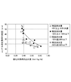
- FIG. 2 is a graph showing the relationship between the average particle diameter of the produced nickel sulfide and the amount of hydrogen sulfide gas blown.
- nickel sulfide having an adjusted particle size is added as a seed crystal, for example, in an amount of 100% by mass to 150% by mass with respect to the amount of nickel contained in the starting solution.
- the supply amount of hydrogen sulfide gas to the nickel sulfate solution so that the addition rate of hydrogen sulfide gas in the first sulfurization reaction tank is in the range of 0.36 to 0.82 Nm 3 / kg-Ni
- the average particle diameter of nickel sulfide precipitated by the reaction could be appropriately controlled in the range of 15 to 55 ⁇ m.
- the seed crystal addition amount is 50% by mass or more and less than 100% by mass and the hydrogen sulfide gas addition rate in the first sulfurization reaction tank is adjusted to about 0.33 to 0.37 Nm 3 / kg-Ni
- nickel Although the particle size of the sulfide tended to be relatively large, the average particle size could be controlled in the range of 40 to 60 ⁇ m.
- the addition amount of nickel sulfide as a seed crystal is set to 100% by mass or more and 150% by mass or less, the nickel concentration in the final solution after the sulfurization reaction tends to increase and the actual nickel yield tends to decrease. I understood that.
- the seed crystal addition amount is 150% by mass or more and 500% by mass or less and the hydrogen sulfide gas addition rate in the first sulfurization reaction tank is adjusted to 0.38 to 0.74 Nm 3 / Kg-Ni
- nickel sulfide Although the particle size of the product tended to be relatively small, the average particle size was 12.4 to 32.0 ⁇ m and could be controlled within a predetermined range.
- the addition amount of nickel sulfide as a seed crystal is set to 100% by mass or more and 150% by mass or less, the nickel concentration in the final solution after the sulfurization reaction tends to increase and the actual nickel yield tends to decrease. I understood that.
- the addition amount of nickel sulfide having a grain size adjusted as a seed crystal was set to an amount of 40% by mass or more and 500% by mass or less with respect to the nickel amount in the sulfurization reaction starting solution, and the sulfurization reaction
- the amount of nickel sulfide obtained is controlled to a predetermined particle size by adjusting the amount of blowing to the range of 0.30 to 0.85 Nm 3 / kg-Ni and blowing hydrogen sulfide gas to cause a sulfurization reaction. It was found that the range can be controlled appropriately.
- the particle size of the nickel sulfide is more preferably in an appropriate range. It was found that the nickel concentration in the final liquid can be kept low, and the decrease in the actual nickel yield can be more effectively suppressed.
- the average particle diameter of the produced nickel sulfide was too large, 100 ⁇ m or more.
- the nickel concentration in the final solution after completion of the sulfurization reaction was as extremely high as 0.32 g / L, and the actual nickel yield was reduced.
- the average particle diameter of the obtained nickel sulfide was 8 ⁇ m.
- the average particle diameter of the produced nickel sulfide was too large, 100 ⁇ m or more.
- the nickel concentration in the final solution after the completion of the sulfurization reaction was as extremely high as 0.30 g / L, and the actual nickel yield was reduced.
- the average particle diameter of the obtained nickel sulfide was 8 ⁇ m.
- the addition amount of nickel sulfide as a seed crystal is in the range of 40 to 500% by mass, and the blowing amount of hydrogen sulfide gas is in the range of 0.30 to 0.85 Nm. It has been found that under conditions exceeding 3 / kg-Ni, the particle size of the nickel sulfide produced is minimized or maximized, and the actual nickel yield decreases.
Landscapes
- Chemical & Material Sciences (AREA)
- Engineering & Computer Science (AREA)
- Organic Chemistry (AREA)
- Manufacturing & Machinery (AREA)
- Materials Engineering (AREA)
- Mechanical Engineering (AREA)
- Metallurgy (AREA)
- General Chemical & Material Sciences (AREA)
- Chemical Kinetics & Catalysis (AREA)
- Life Sciences & Earth Sciences (AREA)
- Environmental & Geological Engineering (AREA)
- General Life Sciences & Earth Sciences (AREA)
- Geochemistry & Mineralogy (AREA)
- Geology (AREA)
- Inorganic Chemistry (AREA)
- Manufacture And Refinement Of Metals (AREA)
Priority Applications (6)
| Application Number | Priority Date | Filing Date | Title |
|---|---|---|---|
| AU2015384934A AU2015384934B2 (en) | 2015-03-05 | 2015-12-01 | Method for producing nickel sulfide and hydrometallurgical method for nickel oxide ore |
| CA2978233A CA2978233C (en) | 2015-03-05 | 2015-12-01 | Method for producing nickel sulfide and hydrometallurgical method for nickel oxide ore |
| CN201580077312.5A CN107429316B (zh) | 2015-03-05 | 2015-12-01 | 镍硫化物的制造方法、镍氧化物矿的湿式冶炼方法 |
| EP15884024.9A EP3266885B1 (en) | 2015-03-05 | 2015-12-01 | Method for producing nickel sulfide and hydrometallurgical method for nickel oxide ore |
| US15/554,869 US10017835B2 (en) | 2015-03-05 | 2015-12-01 | Method for producing nickel sulfide and hydrometallurgical method for nickel oxide ore |
| PH12017501582A PH12017501582B1 (en) | 2015-03-05 | 2017-09-04 | Method for producing nickel sulfide and hydromettalurgical method for nickel oxide ore |
Applications Claiming Priority (2)
| Application Number | Priority Date | Filing Date | Title |
|---|---|---|---|
| JP2015043693A JP6222141B2 (ja) | 2015-03-05 | 2015-03-05 | ニッケル硫化物の製造方法、ニッケル酸化鉱石の湿式製錬方法 |
| JP2015-043693 | 2015-03-05 |
Publications (1)
| Publication Number | Publication Date |
|---|---|
| WO2016139858A1 true WO2016139858A1 (ja) | 2016-09-09 |
Family
ID=56844354
Family Applications (1)
| Application Number | Title | Priority Date | Filing Date |
|---|---|---|---|
| PCT/JP2015/083794 Ceased WO2016139858A1 (ja) | 2015-03-05 | 2015-12-01 | ニッケル硫化物の製造方法、ニッケル酸化鉱石の湿式製錬方法 |
Country Status (8)
| Country | Link |
|---|---|
| US (1) | US10017835B2 (enExample) |
| EP (1) | EP3266885B1 (enExample) |
| JP (1) | JP6222141B2 (enExample) |
| CN (1) | CN107429316B (enExample) |
| AU (1) | AU2015384934B2 (enExample) |
| CA (1) | CA2978233C (enExample) |
| PH (1) | PH12017501582B1 (enExample) |
| WO (1) | WO2016139858A1 (enExample) |
Cited By (3)
| Publication number | Priority date | Publication date | Assignee | Title |
|---|---|---|---|---|
| WO2018101069A1 (ja) * | 2016-11-30 | 2018-06-07 | 住友金属鉱山株式会社 | ニッケル酸化鉱石の湿式製錬方法 |
| JP2018090889A (ja) * | 2016-11-30 | 2018-06-14 | 住友金属鉱山株式会社 | ニッケル酸化鉱石の湿式製錬方法 |
| JP2019183189A (ja) * | 2018-04-03 | 2019-10-24 | 住友金属鉱山株式会社 | 低ニッケル品位酸化鉱石からのニッケルコバルト混合硫化物の製造方法 |
Families Citing this family (1)
| Publication number | Priority date | Publication date | Assignee | Title |
|---|---|---|---|---|
| US20250313491A1 (en) * | 2022-06-10 | 2025-10-09 | Umicore | Process for metal sulphidation |
Citations (3)
| Publication number | Priority date | Publication date | Assignee | Title |
|---|---|---|---|---|
| JP2005350766A (ja) * | 2004-05-13 | 2005-12-22 | Sumitomo Metal Mining Co Ltd | ニッケル酸化鉱石の湿式製錬方法 |
| JP2010031302A (ja) * | 2008-07-25 | 2010-02-12 | Sumitomo Metal Mining Co Ltd | ニッケル酸化鉱石の湿式製錬方法 |
| JP2012031446A (ja) * | 2010-07-28 | 2012-02-16 | Sumitomo Metal Mining Co Ltd | 低品位ニッケル酸化鉱石からのフェロニッケル製錬原料の製造方法 |
Family Cites Families (14)
| Publication number | Priority date | Publication date | Assignee | Title |
|---|---|---|---|---|
| US4547347A (en) | 1983-12-02 | 1985-10-15 | Amax Inc. | Granulometric control of nickel sulfide precipitate |
| JPH0681050A (ja) * | 1991-10-31 | 1994-03-22 | Taiheiyo Kinzoku Kk | ニッケル、コバルトの回収方法 |
| CN1166816C (zh) * | 2000-11-28 | 2004-09-15 | 华东理工大学 | 含镍三氯化铁蚀刻废液再生和镍回收方法 |
| AU2002950815A0 (en) * | 2002-08-15 | 2002-09-12 | Wmc Resources Ltd | Recovery nickel |
| JP4762517B2 (ja) | 2004-09-09 | 2011-08-31 | 株式会社オプトニクス精密 | プリンター用トナーの製造方法 |
| CN1329308C (zh) * | 2005-07-15 | 2007-08-01 | 曹国华 | 从红土镍矿酸浸液中获得硫化镍的方法 |
| CN101466855B (zh) * | 2006-03-31 | 2014-03-26 | 拜奥特克环保技术公司 | 硫化镍沉淀方法 |
| CN102057063A (zh) * | 2008-06-27 | 2011-05-11 | Bhp比利通Ssm开发有限公司 | 用于形成高浓度硫化物的方法 |
| CN101298638B (zh) * | 2008-06-27 | 2010-06-02 | 中南大学 | 一种从红土镍矿浸出液分离富集镍钴的方法 |
| JP5516534B2 (ja) * | 2011-08-22 | 2014-06-11 | 住友金属鉱山株式会社 | ニッケル回収ロスの低減方法、ニッケル酸化鉱石の湿式製錬方法、並びに硫化処理システム |
| JP5257501B2 (ja) * | 2011-11-04 | 2013-08-07 | 住友金属鉱山株式会社 | 鉱石スラリーの製造方法及び金属製錬方法 |
| JP5904459B2 (ja) * | 2011-11-22 | 2016-04-13 | 住友金属鉱山株式会社 | 高純度硫酸ニッケルの製造方法 |
| CN102994746B (zh) * | 2012-11-21 | 2015-04-08 | 广西藤县雅照钛白有限公司 | 工业废酸制取硫化镍精矿的方法 |
| JP5765459B2 (ja) * | 2014-04-02 | 2015-08-19 | 住友金属鉱山株式会社 | ニッケル回収ロスの低減方法、ニッケル酸化鉱石の湿式製錬方法、並びに硫化処理システム |
-
2015
- 2015-03-05 JP JP2015043693A patent/JP6222141B2/ja active Active
- 2015-12-01 WO PCT/JP2015/083794 patent/WO2016139858A1/ja not_active Ceased
- 2015-12-01 EP EP15884024.9A patent/EP3266885B1/en not_active Not-in-force
- 2015-12-01 CN CN201580077312.5A patent/CN107429316B/zh not_active Expired - Fee Related
- 2015-12-01 AU AU2015384934A patent/AU2015384934B2/en active Active
- 2015-12-01 US US15/554,869 patent/US10017835B2/en not_active Expired - Fee Related
- 2015-12-01 CA CA2978233A patent/CA2978233C/en not_active Expired - Fee Related
-
2017
- 2017-09-04 PH PH12017501582A patent/PH12017501582B1/en unknown
Patent Citations (3)
| Publication number | Priority date | Publication date | Assignee | Title |
|---|---|---|---|---|
| JP2005350766A (ja) * | 2004-05-13 | 2005-12-22 | Sumitomo Metal Mining Co Ltd | ニッケル酸化鉱石の湿式製錬方法 |
| JP2010031302A (ja) * | 2008-07-25 | 2010-02-12 | Sumitomo Metal Mining Co Ltd | ニッケル酸化鉱石の湿式製錬方法 |
| JP2012031446A (ja) * | 2010-07-28 | 2012-02-16 | Sumitomo Metal Mining Co Ltd | 低品位ニッケル酸化鉱石からのフェロニッケル製錬原料の製造方法 |
Cited By (4)
| Publication number | Priority date | Publication date | Assignee | Title |
|---|---|---|---|---|
| WO2018101069A1 (ja) * | 2016-11-30 | 2018-06-07 | 住友金属鉱山株式会社 | ニッケル酸化鉱石の湿式製錬方法 |
| JP2018090889A (ja) * | 2016-11-30 | 2018-06-14 | 住友金属鉱山株式会社 | ニッケル酸化鉱石の湿式製錬方法 |
| JP2019183189A (ja) * | 2018-04-03 | 2019-10-24 | 住友金属鉱山株式会社 | 低ニッケル品位酸化鉱石からのニッケルコバルト混合硫化物の製造方法 |
| JP7035735B2 (ja) | 2018-04-03 | 2022-03-15 | 住友金属鉱山株式会社 | 低ニッケル品位酸化鉱石からのニッケルコバルト混合硫化物の製造方法 |
Also Published As
| Publication number | Publication date |
|---|---|
| CA2978233A1 (en) | 2016-09-09 |
| PH12017501582A1 (en) | 2018-02-05 |
| EP3266885A4 (en) | 2018-03-07 |
| CA2978233C (en) | 2019-10-01 |
| PH12017501582B1 (en) | 2022-01-05 |
| EP3266885A1 (en) | 2018-01-10 |
| EP3266885B1 (en) | 2019-01-23 |
| JP6222141B2 (ja) | 2017-11-01 |
| AU2015384934B2 (en) | 2019-05-02 |
| US20180044760A1 (en) | 2018-02-15 |
| JP2016160526A (ja) | 2016-09-05 |
| CN107429316B (zh) | 2019-04-19 |
| CN107429316A (zh) | 2017-12-01 |
| US10017835B2 (en) | 2018-07-10 |
| AU2015384934A1 (en) | 2017-09-21 |
Similar Documents
| Publication | Publication Date | Title |
|---|---|---|
| JP6589950B2 (ja) | 浸出処理方法、ニッケル酸化鉱石の湿式製錬方法 | |
| AU2017218246A1 (en) | Sulfuration treatment method, sulfide production method, and hydrometallurgical process for nickel oxide ore | |
| JP5971364B1 (ja) | 鉱石スラリーの前処理方法、鉱石スラリーの製造方法 | |
| WO2020149122A1 (ja) | 湿式製錬法によるニッケル酸化鉱石からのニッケルコバルト混合硫化物の製造方法 | |
| WO2013027603A1 (ja) | ニッケル回収ロスの低減方法、ニッケル酸化鉱石の湿式製錬方法、並びに硫化処理システム | |
| JP6388043B2 (ja) | 硫化物の製造方法、ニッケル酸化鉱石の湿式製錬方法 | |
| JP6222141B2 (ja) | ニッケル硫化物の製造方法、ニッケル酸化鉱石の湿式製錬方法 | |
| CN107406910B (zh) | 钴粉的制造方法 | |
| JP2017061733A (ja) | ニッケル酸化鉱石の湿式製錬方法、浸出処理設備 | |
| WO2016194709A1 (ja) | 遊離酸除去設備、遊離酸除去方法、ニッケル及びコバルト混合硫化物の製造方法 | |
| JP7200698B2 (ja) | ニッケル酸化鉱石の湿式製錬方法 | |
| JP2021008654A (ja) | ニッケル酸化鉱石の浸出処理方法及びこれを含む湿式製錬方法 | |
| JP2020041194A (ja) | ニッケル酸化鉱石の処理方法及び該処理方法を含んだニッケルコバルト混合硫化物の製造方法 | |
| JP2008231470A (ja) | 硫化工程の反応制御方法 | |
| JP2017201056A (ja) | 中和処理方法、及び中和終液の濁度低減方法 | |
| JP2020180314A (ja) | 水硫化ナトリウム溶液の製造方法、硫化処理方法、ニッケル硫化物の製造方法、及びニッケル酸化鉱石の湿式製錬方法 | |
| JP7293873B2 (ja) | ニッケル硫化物の製造方法、ニッケル酸化鉱石の湿式製錬方法 | |
| JP2014141749A (ja) | ニッケル回収ロスの低減方法、ニッケル酸化鉱石の湿式製錬方法、並びに硫化処理システム | |
| JP2019077928A (ja) | 中和処理方法およびニッケル酸化鉱石の湿式製錬方法 | |
| JP7035735B2 (ja) | 低ニッケル品位酸化鉱石からのニッケルコバルト混合硫化物の製造方法 | |
| JP7585928B2 (ja) | ニッケル酸化鉱石の湿式製錬方法 | |
| JP7585921B2 (ja) | ニッケル酸化鉱石の湿式製錬方法 | |
| JP2019049020A (ja) | ニッケル酸化鉱石の湿式製錬方法 | |
| JP2024017958A (ja) | ニッケル酸化鉱石の湿式製錬方法 | |
| JP2019035132A (ja) | 中和処理方法 |
Legal Events
| Date | Code | Title | Description |
|---|---|---|---|
| 121 | Ep: the epo has been informed by wipo that ep was designated in this application |
Ref document number: 15884024 Country of ref document: EP Kind code of ref document: A1 |
|
| DPE1 | Request for preliminary examination filed after expiration of 19th month from priority date (pct application filed from 20040101) | ||
| ENP | Entry into the national phase |
Ref document number: 2978233 Country of ref document: CA |
|
| WWE | Wipo information: entry into national phase |
Ref document number: 15554869 Country of ref document: US |
|
| WWE | Wipo information: entry into national phase |
Ref document number: 12017501582 Country of ref document: PH |
|
| NENP | Non-entry into the national phase |
Ref country code: DE |
|
| REEP | Request for entry into the european phase |
Ref document number: 2015884024 Country of ref document: EP |
|
| ENP | Entry into the national phase |
Ref document number: 2015384934 Country of ref document: AU Date of ref document: 20151201 Kind code of ref document: A |