WO2016121237A1 - インバータ制御装置及びモータ駆動システム - Google Patents
インバータ制御装置及びモータ駆動システム Download PDFInfo
- Publication number
- WO2016121237A1 WO2016121237A1 PCT/JP2015/084540 JP2015084540W WO2016121237A1 WO 2016121237 A1 WO2016121237 A1 WO 2016121237A1 JP 2015084540 W JP2015084540 W JP 2015084540W WO 2016121237 A1 WO2016121237 A1 WO 2016121237A1
- Authority
- WO
- WIPO (PCT)
- Prior art keywords
- voltage
- high frequency
- unit
- command
- control device
- Prior art date
- Legal status (The legal status is an assumption and is not a legal conclusion. Google has not performed a legal analysis and makes no representation as to the accuracy of the status listed.)
- Ceased
Links
Images


Classifications
-
- H—ELECTRICITY
- H02—GENERATION; CONVERSION OR DISTRIBUTION OF ELECTRIC POWER
- H02P—CONTROL OR REGULATION OF ELECTRIC MOTORS, ELECTRIC GENERATORS OR DYNAMO-ELECTRIC CONVERTERS; CONTROLLING TRANSFORMERS, REACTORS OR CHOKE COILS
- H02P27/00—Arrangements or methods for the control of AC motors characterised by the kind of supply voltage
- H02P27/04—Arrangements or methods for the control of AC motors characterised by the kind of supply voltage using variable-frequency supply voltage, e.g. inverter or converter supply voltage
- H02P27/047—V/F converter, wherein the voltage is controlled proportionally with the frequency
-
- H—ELECTRICITY
- H02—GENERATION; CONVERSION OR DISTRIBUTION OF ELECTRIC POWER
- H02P—CONTROL OR REGULATION OF ELECTRIC MOTORS, ELECTRIC GENERATORS OR DYNAMO-ELECTRIC CONVERTERS; CONTROLLING TRANSFORMERS, REACTORS OR CHOKE COILS
- H02P6/00—Arrangements for controlling synchronous motors or other dynamo-electric motors using electronic commutation dependent on the rotor position; Electronic commutators therefor
- H02P6/14—Electronic commutators
- H02P6/16—Circuit arrangements for detecting position
- H02P6/18—Circuit arrangements for detecting position without separate position detecting elements
-
- H—ELECTRICITY
- H02—GENERATION; CONVERSION OR DISTRIBUTION OF ELECTRIC POWER
- H02P—CONTROL OR REGULATION OF ELECTRIC MOTORS, ELECTRIC GENERATORS OR DYNAMO-ELECTRIC CONVERTERS; CONTROLLING TRANSFORMERS, REACTORS OR CHOKE COILS
- H02P21/00—Arrangements or methods for the control of electric machines by vector control, e.g. by control of field orientation
- H02P21/14—Estimation or adaptation of machine parameters, e.g. flux, current or voltage
- H02P21/18—Estimation of position or speed
-
- H—ELECTRICITY
- H02—GENERATION; CONVERSION OR DISTRIBUTION OF ELECTRIC POWER
- H02P—CONTROL OR REGULATION OF ELECTRIC MOTORS, ELECTRIC GENERATORS OR DYNAMO-ELECTRIC CONVERTERS; CONTROLLING TRANSFORMERS, REACTORS OR CHOKE COILS
- H02P21/00—Arrangements or methods for the control of electric machines by vector control, e.g. by control of field orientation
- H02P21/22—Current control, e.g. using a current control loop
-
- H—ELECTRICITY
- H02—GENERATION; CONVERSION OR DISTRIBUTION OF ELECTRIC POWER
- H02P—CONTROL OR REGULATION OF ELECTRIC MOTORS, ELECTRIC GENERATORS OR DYNAMO-ELECTRIC CONVERTERS; CONTROLLING TRANSFORMERS, REACTORS OR CHOKE COILS
- H02P21/00—Arrangements or methods for the control of electric machines by vector control, e.g. by control of field orientation
- H02P21/24—Vector control not involving the use of rotor position or rotor speed sensors
-
- H—ELECTRICITY
- H02—GENERATION; CONVERSION OR DISTRIBUTION OF ELECTRIC POWER
- H02P—CONTROL OR REGULATION OF ELECTRIC MOTORS, ELECTRIC GENERATORS OR DYNAMO-ELECTRIC CONVERTERS; CONTROLLING TRANSFORMERS, REACTORS OR CHOKE COILS
- H02P27/00—Arrangements or methods for the control of AC motors characterised by the kind of supply voltage
- H02P27/04—Arrangements or methods for the control of AC motors characterised by the kind of supply voltage using variable-frequency supply voltage, e.g. inverter or converter supply voltage
- H02P27/06—Arrangements or methods for the control of AC motors characterised by the kind of supply voltage using variable-frequency supply voltage, e.g. inverter or converter supply voltage using DC to AC converters or inverters
- H02P27/08—Arrangements or methods for the control of AC motors characterised by the kind of supply voltage using variable-frequency supply voltage, e.g. inverter or converter supply voltage using DC to AC converters or inverters with pulse width modulation
- H02P27/085—Arrangements or methods for the control of AC motors characterised by the kind of supply voltage using variable-frequency supply voltage, e.g. inverter or converter supply voltage using DC to AC converters or inverters with pulse width modulation wherein the PWM mode is adapted on the running conditions of the motor, e.g. the switching frequency
-
- H—ELECTRICITY
- H02—GENERATION; CONVERSION OR DISTRIBUTION OF ELECTRIC POWER
- H02P—CONTROL OR REGULATION OF ELECTRIC MOTORS, ELECTRIC GENERATORS OR DYNAMO-ELECTRIC CONVERTERS; CONTROLLING TRANSFORMERS, REACTORS OR CHOKE COILS
- H02P6/00—Arrangements for controlling synchronous motors or other dynamo-electric motors using electronic commutation dependent on the rotor position; Electronic commutators therefor
- H02P6/14—Electronic commutators
- H02P6/16—Circuit arrangements for detecting position
- H02P6/18—Circuit arrangements for detecting position without separate position detecting elements
- H02P6/183—Circuit arrangements for detecting position without separate position detecting elements using an injected high frequency signal
-
- H—ELECTRICITY
- H02—GENERATION; CONVERSION OR DISTRIBUTION OF ELECTRIC POWER
- H02M—APPARATUS FOR CONVERSION BETWEEN AC AND AC, BETWEEN AC AND DC, OR BETWEEN DC AND DC, AND FOR USE WITH MAINS OR SIMILAR POWER SUPPLY SYSTEMS; CONVERSION OF DC OR AC INPUT POWER INTO SURGE OUTPUT POWER; CONTROL OR REGULATION THEREOF
- H02M1/00—Details of apparatus for conversion
- H02M1/0003—Details of control, feedback or regulation circuits
- H02M1/0006—Arrangements for supplying an adequate voltage to the control circuit of converters
-
- H—ELECTRICITY
- H02—GENERATION; CONVERSION OR DISTRIBUTION OF ELECTRIC POWER
- H02M—APPARATUS FOR CONVERSION BETWEEN AC AND AC, BETWEEN AC AND DC, OR BETWEEN DC AND DC, AND FOR USE WITH MAINS OR SIMILAR POWER SUPPLY SYSTEMS; CONVERSION OF DC OR AC INPUT POWER INTO SURGE OUTPUT POWER; CONTROL OR REGULATION THEREOF
- H02M1/00—Details of apparatus for conversion
- H02M1/0003—Details of control, feedback or regulation circuits
- H02M1/0009—Devices or circuits for detecting current in a converter
-
- H—ELECTRICITY
- H02—GENERATION; CONVERSION OR DISTRIBUTION OF ELECTRIC POWER
- H02P—CONTROL OR REGULATION OF ELECTRIC MOTORS, ELECTRIC GENERATORS OR DYNAMO-ELECTRIC CONVERTERS; CONTROLLING TRANSFORMERS, REACTORS OR CHOKE COILS
- H02P25/00—Arrangements or methods for the control of AC motors characterised by the kind of AC motor or by structural details
- H02P25/02—Arrangements or methods for the control of AC motors characterised by the kind of AC motor or by structural details characterised by the kind of motor
- H02P25/08—Reluctance motors
Definitions
- Embodiments of the present invention relate to an inverter control device.
- An inverter control device includes an inverter main circuit, a current command generation unit, a voltage command generation unit, an estimation unit, and a high frequency superposition unit.
- the inverter main circuit can be electrically connected to a predetermined rotational drive target.
- the current command generation unit generates a current command.
- the voltage command generation unit generates a voltage command in which the current output from the inverter main circuit is equal to the current command.
- the estimation unit calculates an estimated rotation phase angle of the rotation drive target.
- the high frequency superimposing unit superimposes the high frequency on the current command or the voltage command in accordance with the relationship between the feature value of the rotational drive target and the threshold value.
- generation part of FIG. The figure which shows the inductance table of FIG.
- the figure which shows the electric current phase angle table of FIG. The figure which shows the structure of the voltage command production
- FIG. 14 is a diagram for explaining the operation of the bandpass filter of FIG. 13.
- movement of the FFT analysis part of FIG. The figure which shows an example of high frequency current idc 'and iqc'.
- movement of the high frequency superimposition part of FIG. The figure which shows the structure of the modification of a high frequency superimposition part.
- FIG. 1 The figure explaining the other example of operation
- generation part of FIG. The figure which shows the structure of the control system switching part of FIG.
- FIG. 1 is a diagram illustrating a configuration of a motor drive system according to the present embodiment.
- the motor drive system according to the present embodiment includes a motor 1 and an inverter control device 2 (hereinafter referred to as “control device 2”).
- the motor 1 is a rotational drive target of the control device 2 and is connected to the control device 2.
- the SynRM 1 includes a stator and a rotor.
- the stator has three excitation phases (U phase, V phase, and W phase).
- the stator generates a magnetic field by a three-phase alternating current flowing in each excitation phase.
- the rotor does not have a permanent magnet and rotates by magnetic interaction with the magnetic field generated by the stator.
- the control device 2 controls the rotational phase angle ⁇ of the SynRM 1 without the rotational phase sensor.
- the control device 2 includes an inverter main circuit 21, a current detector 22, a coordinate conversion unit 23, a current command generation unit 24, a voltage command generation unit 25, and a coordinate A conversion unit 26, a PWM modulation unit 27, a speed / rotation phase angle estimation unit 28, an adder 29, and a high frequency superimposing unit 30 are provided.
- the inverter main circuit 21 is a circuit including a switching element.
- the inverter main circuit 21 converts power from a power source (not shown) into alternating current by switching ON / OFF of the switching element, and supplies it to SynRM1.
- the inverter main circuit 21 receives a control signal for controlling ON / OFF of each switching element from the PWM modulation unit 27.
- the current detector 22 detects a two-phase or three-phase current among the three-phase AC current flowing through the stator of the SynRM1.
- FIG. 1 shows a configuration for detecting two-phase (U-phase and W-phase) currents iu and iw. Note that the three-phase alternating current flowing through the stator of the SynRM 1 may be obtained by calculation based on the direct current on the inverter main circuit 21.
- the coordinate conversion unit 23 converts the currents iu and iw detected by the current detector 22 from the three-phase fixed coordinate system to the dcqc axis rotation coordinate system, and generates currents idc and iqc.
- the current idc is a dc axis component of the current flowing through the stator
- the current iqc is a qc axis component of the current flowing through the stator.
- the three-phase fixed coordinate system is a fixed coordinate system composed of an ⁇ axis and a ⁇ axis.
- the ⁇ axis is set in the U-phase direction
- the ⁇ axis is set in a direction perpendicular to the ⁇ axis.
- the currents iu and iw detected by the current detector 22 are represented on such three-phase fixed coordinates.
- the dcqc axis rotational coordinate system is a rotational coordinate system composed of a dc axis and a qc axis.
- the dc axis is set in the direction estimated by the control device 2 as the d-axis direction (the direction in which the rotor inductance is minimum), and the qc axis is the q-axis direction in the q-axis direction (the direction in which the rotor inductance is maximum). Is set in the estimated direction.
- the inductance ellipse in FIG. 2 indicates the inductance of the rotor.
- the dcqc axis and the dq axis do not always coincide with each other.
- the actual rotational phase angle ⁇ of the rotor is represented by an angle from the ⁇ axis to the d axis.
- the estimated rotational phase angle ⁇ est of the rotor estimated by the control device 2 is represented by an angle from the ⁇ axis to the dc axis.
- an error between the rotational phase angle ⁇ and the estimated rotational phase angle ⁇ est is referred to as an error ⁇ .
- the coordinate conversion unit 23 can convert the three-phase fixed coordinate system into the dcqc axis rotation coordinate system by using the estimated rotation phase angle ⁇ est output from the speed / rotation phase angle estimation unit 28.
- the current command generator 24 generates current commands idc * and iqc * based on the torque command T * and the estimated speed ⁇ est.
- the torque command T * is a torque value generated in the rotor. In the present embodiment, it is assumed that the torque command T * is input from an external device.
- the estimated speed ⁇ est is the rotor speed ⁇ estimated by the control device 2.
- the current command idc * is a dc axis component of a current that flows through SynRM1.
- the current command iqc * is a qc-axis component of a current that flows through the SynRM1.
- FIG. 3 is a diagram illustrating a configuration of the current command generation unit 24.
- the current command generator 24 includes an inductance table 31 and a current phase angle table 32.
- the inductance table 31 is a table showing the relationship between the current command and the inductance. As shown in FIG. 4, the inductance table 31 includes a table indicating the relationship between the current command idc * and the inductance Ld and a table indicating the relationship between the current command iqc * and the inductance Lq.
- the inductance Ld is a d-axis component of the inductance of SynRM1
- the inductance Lq is a q-axis component of the inductance of SynRM1.
- the current command idc * is fed back to iqc *, the current command idc *, iqc * in accordance inductance Ld, may output the Lq.
- the current phase angle table 32 is a table showing the relationship between the torque command T * and the estimated angular velocity ⁇ * and the current phase angle ⁇ .
- the current phase angle ⁇ is the phase angle of the current vector corresponding to the current flowing through the stator.
- the current phase angle table 32 receives the torque command T * and the estimated speed ⁇ * , and outputs a current phase angle ⁇ corresponding to the torque command T * and the estimated angular speed ⁇ * .
- the current command generator 24 calculates the current Idq based on the torque command T * , the inductances Ld and Lq, and the current phase angle ⁇ .
- the current Idq is the magnitude of the current flowing through the stator.
- the current Idq is calculated by the following formula.
- P is the number of pole pairs of SynRM1.
- the current command generator 24 generates current commands idc * and iqc * from the current Idq and the current phase angle ⁇ .
- the current command idc * is a dc-axis component of a current vector whose magnitude is the current Idq and whose phase angle is the current phase angle ⁇ .
- the current command iqc * is a qc-axis component of a current vector having a current Idq and a phase angle ⁇ .
- the method of calculating the current commands idc * and iqc * is not limited to the above method, and can be arbitrarily selected.
- the voltage command generation unit 25 (current control unit) is configured to output a current output from the inverter main circuit 21 based on the currents idc and iqc, the current commands idc * and iqc * , and the estimated speed ⁇ est (that is, a current flowing through the SynRM1). Voltage commands vdc * and vqc * are generated so that becomes current commands idc * and iqc * .
- the voltage command vdc * is a dc axis component of a voltage applied to the stator of SynRM1.
- the voltage command vqc * is a qc-axis component of a voltage applied to the stator of SynRM1.
- FIG. 6 is a diagram illustrating a configuration of the voltage command generation unit 25.
- the voltage command generation unit 25 includes a PI controller 41, a feedforward command generation unit 42, and adders 43 and 44.
- the PI controller 41 receives the currents idc and iqc and the current commands idc * and iqc * , and calculates the voltages ACRd and ACRq at which the currents idc and iqc become the current commands idc * and iqc * by PI control.
- the voltages ACRd and ACRq are voltages generated according to the error ⁇ , and when the set motor parameter matches the true value and the error ⁇ is 0, both are 0.
- the voltages ACRd and ACRq output from the PI controller 41 are input to adders 43 and 44, respectively.
- Feedforward command generating unit 42 current command idc *, and iqc *, is input and estimated speed .omega.est, the feedforward voltage Vd_ FF, generates a Vq_ FF.
- R is the winding resistance of the stator.
- Feedforward command generating unit 42 is feedforward voltage Vd_ FF outputted, Vq_ FF is inputted to adders 43 and 44.
- the adder 43 adds the voltage ACRd and feedforward voltage Vd_ FF, generates a voltage command vdc *.
- the adder 44 adds the voltage ACRq and feedforward voltage Vq_ FF, generates a voltage command Vdq *.
- the coordinate conversion unit 26 converts the voltage command vdc * output from the voltage command generation unit 25 and the voltage output from the adder 29 from the dcqc axis rotation coordinate system to the three-phase fixed coordinate system. As with the coordinate conversion unit 23, the coordinate conversion unit 26 converts the dcqc axis rotation coordinate system into a three-phase fixed coordinate system by using the estimated rotation phase angle ⁇ est.
- the voltages coordinate-converted by the coordinate conversion unit 26 are referred to as voltage commands vu * , vv * , vw * .
- the voltage command vu * is a voltage applied to the U phase of the stator
- the voltage command vv * is a voltage applied to the V phase of the stator
- the voltage command vw * is applied to the W phase of the stator. Voltage.
- the PWM modulation unit 27 modulates the voltage commands vu * , vv * , and vw * by PWM (Pulse-Width Modulation) using a triangular wave, and is a binary value corresponding to ON or OFF of each switching element of the inverter main circuit 21. Control signal is generated.
- the PWM modulation unit 27 inputs the generated control signal to the inverter main circuit 21.
- the speed / rotation phase angle estimation unit 28 (hereinafter referred to as “estimation unit 28”) estimates the rotor speed ⁇ and the rotation phase angle ⁇ of the SynRM 1 based on the voltage commands vdc * and vqc * and the currents idc and iqc. Then, the estimated speed ⁇ est and the estimated rotational phase angle ⁇ est are calculated.
- the estimated speed ⁇ est output from the estimation unit 28 is input to the current command generation unit 24, the voltage command generation unit 25, and the high frequency superimposition unit 30.
- the estimated rotational phase angle ⁇ est is input to the coordinate conversion units 23 and 26 and used for coordinate conversion.
- the estimation unit 28 estimates the speed ⁇ and the rotation phase angle ⁇ using the expansion induced voltage.
- an estimation method using the extended induced voltage will be described.
- vd is the d-axis component of the voltage applied to SynRM1
- vq is the q-axis component of the voltage applied to SynRM1
- id is the d-axis component of the current flowing through SynRM1
- iq is the current flowing through SynRM1.
- q-axis component, p is a differential operator (d / dt).
- Equation (4) vdc is a dc axis component of the voltage applied to SynRM1, and vqc is a qc axis component of the voltage applied to SynRM1.
- Equation (3) is expressed as follows.
- the voltage Ex represented by the above formula (12) is referred to as an extended induced voltage.
- Equation (14) When the terms of Equation (14) are divided, the following equation is established.
- the estimation unit 28 can calculate the estimated speed ⁇ est by calculating the error ⁇ based on the equation (16) and performing the PLL control so that the error ⁇ becomes 0, thereby calculating the estimated speed ⁇ est. Further, by integrating the estimated speed ⁇ est, the rotational phase angle ⁇ can be estimated and the estimated rotational phase angle ⁇ est can be calculated.
- FIG. 7 is a diagram illustrating a configuration of the estimation unit 28 that estimates the speed ⁇ and the rotation phase angle ⁇ by the above-described method.
- the estimation unit 28 includes a high frequency detection unit 51, a ⁇ calculation unit 52, a PLL control unit 53, and an integrator 54.
- the high frequency detector 51 detects the high frequency components of the currents idc and iqc and calculates the current differential terms pidc and picc.
- the current differential terms pidc and piqc output from the high frequency detection unit 51 are input to the ⁇ calculation unit 52.
- the error ⁇ calculated by the ⁇ calculation unit 52 is input to the PLL control unit 53. The details of the high-frequency detector 51 will be described later.
- the PLL control unit 53 performs PLL control so that the error ⁇ becomes 0, and calculates the estimated speed ⁇ est.
- the estimated speed ⁇ est output from the PLL control unit 53 is input to the integrator 54.
- the integrator 54 integrates the estimated speed ⁇ est to calculate the estimated rotational phase angle ⁇ est.
- the adder 29 adds the voltage command vdc * output from the voltage command generator 25 and the high frequency voltage vh output from the high frequency superimposing unit 30. Thereby, the high frequency voltage vh is superimposed on the voltage command vdc * .
- the voltage command vdc * superimposed with the high frequency voltage vh is input to the coordinate conversion unit 26.
- the high frequency superimposing unit 30 outputs the high frequency voltage vh when the voltage amplitude command Vdqc * or the power Pm of the SynRM 1 is lower than the threshold value.
- the power Pm is the rated output (shaft output) of SynRM1.
- the output high frequency voltage vh is superimposed on the voltage command vdc * by the adder 29.
- the reason why the high-frequency voltage vh is superimposed on the voltage command vdc * will be described.
- the estimation unit 28 calculates the error ⁇ using the extended induced voltage Ex, and estimates the speed ⁇ and the rotation phase angle ⁇ .
- the expansion induced voltage Ex of Expression (12) is small.
- FIG. 8 and FIG. 9 are diagrams showing the characteristics of torque, power Pm, and voltage amplitude command Vdqc * with respect to the speed of conventional PMSM and SynRM.
- FIG. 8 shows characteristics at the time of heavy load in which each motor outputs a large torque.
- FIG. 9 shows characteristics at light loads where each motor outputs a small torque.
- the conventional PMSM and SynRM can obtain a sufficient expansion induced voltage Ex at the time of heavy load. For this reason, the control device for controlling PMSM and SynRM performs stable control without stepping out PMSM and SynRM even if the superposition of the high-frequency voltage vh on the voltage command vdc * is stopped with a certain speed ⁇ n as a reference. Can continue.
- the conventional PMSM generates a magnet voltage corresponding to the rotational speed even at a light load, so that a relatively large expansion induced voltage Ex can be obtained.
- the control device that controls PMSM can control PMSM without stepping out even if superposition of high-frequency voltage vh to voltage command vdc * is stopped with reference to a certain speed ⁇ n.
- the control device 2 superimposes the high frequency voltage vh on the voltage command vdc * when the voltage amplitude command Vdqc * or the power Pm of the SynRM 1 is lower than the threshold value.
- the expansion induced voltage Ex is increased to stabilize the control of SynRM1.
- the dc-axis current differential term of Equation (4) is as follows when ⁇ is extremely small.
- FIG. 11 is a diagram illustrating an example of the configuration of the high-frequency superimposing unit 30.
- the high frequency superimposing unit 30 in FIG. 11 switches the presence / absence of high frequency superimposition based on the power Pm of SynRM1.
- the high frequency superimposing unit 30 includes a determination unit 60.
- the determination unit 60 determines whether to superimpose the high-frequency voltage vh based on the power Pm of SynRM1.
- the determination unit 60 outputs a signal corresponding to the determination result.
- the determination unit 60 outputs 0 when it is determined that the expansion induced voltage Ex is large, and outputs 1 when it is determined that the expansion induced voltage Ex is small.
- the high frequency superimposing unit 30 does not output the high frequency voltage vh when the determining unit 60 determines that the expansion induced voltage Ex is large (outputs 0). In this case, the voltage command vdc * is input to the coordinate conversion unit 26.
- the high frequency superimposing unit 30 outputs the high frequency voltage vh when the determining unit 60 determines that the load is small (outputs 1).
- the voltage command vdc * obtained by adding the high frequency voltage vh by the adder 29 is input to the coordinate conversion unit 26.
- the high frequency voltage vh is expressed by the following equation.
- Vh is an amplitude setting value
- fh is a frequency setting value
- FIG. 12 is a diagram illustrating an example of the determination unit 60 in FIG.
- the determination unit 60 determines whether high-frequency superimposition is necessary based on the power Pm of SynRM1. Specifically, the determination unit 60 calculates the power Pm of the SynRM 1 based on the torque command T * and the estimated speed ⁇ est, and compares the power Pm with a predetermined threshold value Pr. The determination unit 60 determines that the load is small when the power Pm is smaller than the threshold Pr (Pm ⁇ Pr).
- the threshold value Pr is set so that the estimation accuracy of the speed ⁇ and the rotational phase angle ⁇ is improved. For example, when the minimum value that can accurately estimate the rotational phase angle ⁇ using the extended induced voltage Ex is n, the extended induced voltage Ex corresponding to the threshold Pr when the motor pole pair number is 1 is expressed by the following equation.
- the threshold value Pr that satisfies the minimum value of the extended induced voltage n that can accurately estimate the rotational phase angle ⁇ from Equations (22) and (23) is as follows.
- the determination unit 60 may calculate the threshold value Pr that satisfies Equation (24) sequentially or in advance and compare it with the power Pm. Thereby, when the power Pm is smaller than the threshold value Pr, the high frequency voltage vh is superimposed on the voltage command vdc * .
- the power Pm may be calculated using the following mathematical formula instead of formula (23).
- the high frequency superimposing unit 30 may switch the presence / absence of high frequency superposition based on the voltage amplitude command Vdqc * of SynRM1. In this case, voltage commands vdc * and vqc * are input to the high frequency superimposing unit 30 instead of the torque command T * and the estimated speed ⁇ est.
- the determination unit 60 calculates the voltage amplitude command Vdqc * of SynRM1 based on the voltage commands vdc * and vqc * , compares the voltage amplitude command Vdqc * with the threshold value Vr, and compares Vdqc *. If ⁇ Vr, it may be determined that the load is small. Thereby, when the voltage amplitude command Vdqc * is smaller than the threshold value Vr, the high frequency voltage vh is superimposed on the voltage command vqc * .
- the high frequency superimposing unit 30 superimposes the high frequency voltage vh on the voltage command vdc * to increase the expansion induced voltage Ex, and the speed ⁇ and the rotation phase angle using the expansion induced voltage Ex.
- the estimation accuracy of ⁇ can be improved.
- the high frequency superimposing unit 30 superimposes the high frequency voltage vh on the voltage command vqc * when the load of the SynRM 1 is small.
- the estimation unit 28 calculates the error ⁇ by Expression (16) when the high-frequency voltage vh is not superimposed, and calculates the error ⁇ by Expression (20) when the high-frequency voltage vh is superimposed.
- the high frequency detection unit 51 calculates the current differential terms pidc and picc.
- the estimation unit 28 calculates the error ⁇ by substituting the current differential terms pidc and piqc calculated by the high frequency detection unit 51 into the equation (20).
- FIG. 14 is a diagram illustrating a configuration of the high-frequency detection unit 51.
- the high frequency detection unit 51 includes a band pass filter 55 and an FFT analysis unit 56.
- the band-pass filter 55 passes a frequency component in a predetermined range including the frequency fh of the high-frequency voltage vh out of the input currents idc and iqc, and attenuates the frequency component outside the range. Thereby, the band pass filter 55 detects the high frequency currents idc ′ and iqc ′ having the frequency fh from the currents idc and idq.
- the high-frequency currents idc ′ and iqc ′ output from the bandpass filter 55 are input to the FFT analysis unit 56.
- the extra high frequency currents idc ′ and iqc ′ have their extra frequency components removed by the band pass filter 55. Therefore, the FFT analyzer 56 can calculate the amplitudes idc′pp and iqc′pp with high accuracy as shown in FIG.
- the high-frequency detector 51 calculates the current differential terms pidc and picc by dividing the amplitudes idc′pp and iqc′pp calculated by the FFT analyzer 56 by the sampling period dt, respectively.
- the inverter control device 2 superimposes the high-frequency voltage vh on the voltage command vqc * when the load of the SynRM 1 is low.
- the extended induced voltage Ex is increased and the rotational phase angle ⁇ and the speed ⁇ of the SynRM1 are accurately determined using the expanded induced voltage Ex. Can be estimated well. Therefore, instability and step-out of the control of SynRM1 can be suppressed.
- the inverter control device 2 may be a PMSM or a winding field that supplies field magnetic flux by a secondary winding. It can also be used as a control device for a synchronous machine.
- the inverter control device 2 may superimpose the high frequency voltage vh on the voltage command vqc * , or may superimpose the high frequency current on the current commands idc * and iqc * . In either case, since the expansion induced voltage Ex can be increased, the above-described effect can be obtained.
- the high frequency superimposing unit 30 may switch the presence / absence of high frequency superposition based on the rotational phase angle error ⁇ of the SynRM 1.
- the error ⁇ calculated by the estimating unit 28 is input to the high frequency superimposing unit 30 instead of the torque command T * and the estimated speed ⁇ est.
- the determination unit 60 may compare the error ⁇ with the threshold value ⁇ r and determine that the load is small when
- the rotational phase angle error ⁇ is controlled to approach zero, and when the error ⁇ exceeds the threshold value, the phase angle error can be easily converged to zero by superimposing high frequency. Instability and step-out of the control of SynRM1 can be suppressed.
- the inverter control device 2 can be applied not only to sensorless control using the expanded induced voltage Ex but also to sensorless control using an observer or PWM harmonics.
- the inverter control device 2 may control the SynRM 1 without the current sensor 22 and without a current sensor. In this case, the same effect can be obtained.
- FIG. 19 is a diagram illustrating a configuration of the high frequency superimposing unit 30. As shown in FIG. 19, the high frequency superimposing unit 30 further includes an amplitude calculating unit 61.
- the amplitude calculation unit 61 calculates the amplitude Vh of the high-frequency voltage vh based on the power Pm of the SynRM 1 or the voltage amplitude command Vdqc * .
- the amplitude calculating unit 61 calculates the amplitude Vh so that the smaller the power Pm or the voltage amplitude command Vdqc * of the SynRM 1 is.
- the amplitude calculation unit 61 calculates the amplitude Vh by the following formula based on the torque command T * and the estimated speed ⁇ est. calculate.
- the amplitude Vh increases as the power Pm decreases. What is necessary is just to determine the value of amplitude Vh so that the relationship of Formula (24) may be satisfy
- the amplitude calculation unit 61 may calculate the amplitude Vh by the following equation.
- the amplitude Vh decreases in inverse proportion to the speed ⁇ without depending on the voltage amplitude command Vdqc * when a constant current is applied, and has a characteristic as shown in FIG.
- the inverter control device 2 can vary the superposed high-frequency voltage vh using the relationship between the speed ⁇ and the expansion induced voltage Ex.
- the high frequency superimposing unit 30 may change the frequency fh of the high frequency current vh according to the load of the SynRM 1. Further, the high frequency superimposing unit 30 may change the amplitude Vh according to the estimated speed ⁇ est and the torque command T * without being limited to the power Pm and the voltage amplitude command Vdqc * .
- the inverter control device 2 according to the present embodiment uses two types of estimation methods of the rotational phase angle ⁇ and the speed ⁇ , and switches between these estimation methods according to the load of the SynRM 1.
- FIG. 22 is a diagram showing a configuration of a motor drive system according to the present embodiment. As shown in FIG. 22, the inverter control device 2 according to the present embodiment further includes a control method switching unit 70. Hereinafter, differences from the first embodiment will be described.
- the voltage command generator 25 outputs the voltage ACRd together with the voltage commands vdc * and vqc * .
- the voltage ACRd output from the voltage command generation unit 25 is input to the estimation unit 28.
- the control method switching unit 70 outputs a binary control switching signal according to the voltage amplitude command Vdqc * or the power Pm of SynRM1.
- the control method such as the estimation method of the rotational phase angle ⁇ and the speed ⁇ is switched by this control switching signal.
- the control method switching unit 70 outputs 0 when the voltage amplitude command Vdqc * or the power Pm is small, and outputs 1 when the voltage amplitude command Vdqc * or the power Pm is large.
- the control method switching unit 70 calculates the voltage amplitude command Vdqc * of SynRM1 based on the voltage commands vdc * and vqc * , compares the voltage amplitude command Vdqc * with the threshold value Vr, and compares Vdqc *. If ⁇ Vr, it may be determined that the load is small.
- control method switching unit 70 calculates the power Pm of the SynRM 1 based on the torque command T * and the estimated speed ⁇ est, compares the power Pm with a predetermined threshold Pr, and the load is small when Pm ⁇ Pr. May be determined.
- control method switching unit 70 may compare the estimated speed ⁇ est with a predetermined threshold value ⁇ r and determine that the high frequency voltage vh needs to be superimposed when ⁇ est ⁇ r.
- the high frequency superimposing unit 30 receives a control switching signal from the control method switching unit 70.
- the high frequency superimposing unit 30 outputs the high frequency voltage vh when 0 is input as the control switching signal, and does not output the high frequency voltage vh when 1 is input as the control switching signal.
- the high frequency voltage vh output from the high frequency superimposing unit 30 is input to the estimating unit 28 and the adder 29.
- the adder 29 adds the voltage command vdc * and the high-frequency voltage vh and inputs them to the coordinate conversion unit 26. Thereby, the high frequency voltage vh is superimposed on the voltage command vdc * .
- the estimation unit 28 includes a PLL control unit 53, an integrator 54, a first estimation unit 57, a second estimation unit 58, and a switch 59.
- the first estimation unit 57 and the second estimation unit 58 calculate the error ⁇ by different methods.
- the first estimation unit 57 calculates the error ⁇ based on the high frequency voltage vh and the current idc.
- the current differential term pidc is expressed by the following equation.
- the first estimation unit 57 calculates the error ⁇ based on the equation (29).
- Second estimation unit 58 calculates an error ⁇ by using the voltage ACRd the PI controller 41 is output, feedforward voltage Vd_ FF, and Vq_ FF, the relationship. Specifically, the second estimation unit 58 calculates the error ⁇ based on the currents idc and iqc and the voltage ACRd.
- the second estimation unit 58 calculates the error ⁇ based on the equation (32).
- the switch 59 switches the error ⁇ input to the PLL control unit 53 in accordance with the control switching signal.
- the switch 59 inputs the error ⁇ output from the first estimation unit 57 to the PLL control unit 53 when 0 is input as the control switching signal.
- the switch 59 inputs the error ⁇ output from the first estimation unit 58 to the PLL control unit 53 when 1 is input as the control switching signal.
- the PLL control unit 53 performs PLL control on the error ⁇ , and calculates the estimated speed ⁇ est.
- the integrator 54 integrates the estimated speed ⁇ est to calculate the estimated rotational phase angle ⁇ est.
- the inverter control device 2 includes the first control method that estimates the rotational phase using the harmonic current generated by superimposing the high-frequency voltage vh.
- the SynRM 1 is controlled by using two types of control methods, that is, a second control method that estimates the rotational phase using the voltage generated by the flux linkage.
- the inverter control unit 2 In the first control mode, the inverter control unit 2 superimposes a high frequency voltage vh to the voltage command vdc *, calculates an error ⁇ based on the high-frequency voltage vh voltage command vdc superimposed *, based on the error ⁇ Thus, the rotational phase angle ⁇ and the speed ⁇ are estimated. Thereby, the inverter control apparatus 2 can enlarge the expansion induced voltage Ex, and can improve the estimation precision of rotational phase angle (theta) and speed (omega).
- the inverter control device 2 estimates the rotational phase angle ⁇ and the speed ⁇ without superimposing the high-frequency voltage vh on the voltage command vdc * . Thereby, the inverter control apparatus 2 can reduce a torque ripple and the noise resulting from it, a noise, and a high frequency loss.
- any method that does not use the high-frequency voltage vh can be selected as a method for calculating the error ⁇ by the second estimating unit 58.
- the second estimation unit 58 may calculate the error ⁇ using an observer or voltages ACRd and ACRq.
- control method switching unit 70 may be configured so that the control switching signal is not frequently changed by a hysteresis operation.
- the present invention is not limited to the above-described embodiments as they are, and can be embodied by modifying the constituent elements without departing from the scope of the invention in the implementation stage.
- various inventions can be formed by appropriately combining a plurality of constituent elements disclosed in the above embodiments. Further, for example, a configuration in which some components are deleted from all the components shown in each embodiment is also conceivable. Furthermore, you may combine suitably the component described in different embodiment.
Landscapes
- Engineering & Computer Science (AREA)
- Power Engineering (AREA)
- Control Of Ac Motors In General (AREA)
- Control Of Electric Motors In General (AREA)
- Control Of Motors That Do Not Use Commutators (AREA)
Abstract
【課題】 モータの回転位相角を精度よく推定できるインバータ制御装置及びモータ駆動システムを提供する。 【解決手段】 一実施形態に係るインバータ制御装置は、インバータ主回路と、電流指令生成部と、電圧指令生成部と、推定部と、高周波重畳部と、を備える。インバータ主回路は、所定の回転駆動対象と電気的に接続可能である。電流指令生成部は、電流指令を生成する。電圧指令生成部は、インバータ主回路から出力される電流が、電流指令と等しくなる電圧指令を生成する。推定部は、回転駆動対象の推定回転位相角を算出する。高周波重畳部は、回転駆動対象の特徴量と閾値との関係に応じて、電流指令又は電圧指令に、高周波を重畳する。
Description
本発明の実施形態は、インバータ制御装置に関する。
従来、永久磁石同期モータ(PMSM)やシンクロナスリラクタンスモータ(SynRM)の回転位相角センサレス制御において、高速域では誘起電圧を利用した回転位相角の推定方法が利用されている。しかしながら、磁石磁束が小さいPMSMや、SynRMでは、高速域であっても、低負荷の状態では、鎖交磁束により生じる誘起電圧が小さいため、回転位相角の推定精度が悪化するという問題があった。
モータの回転位相角を精度よく推定できるインバータ制御装置及びモータ駆動システムを提供する。
一実施形態に係るインバータ制御装置は、インバータ主回路と、電流指令生成部と、電圧指令生成部と、推定部と、高周波重畳部と、を備える。インバータ主回路は、所定の回転駆動対象と電気的に接続可能である。電流指令生成部は、電流指令を生成する。電圧指令生成部は、インバータ主回路から出力される電流が、電流指令と等しくなる電圧指令を生成する。推定部は、回転駆動対象の推定回転位相角を算出する。高周波重畳部は、回転駆動対象の特徴量と閾値との関係に応じて、電流指令又は電圧指令に、高周波を重畳する。
以下、本発明の実施形態について図面を参照して説明する。
(第1実施形態)
第1実施形態に係るインバータ制御装置について、図1~図21を参照して説明する。図1は、本実施形態に係るモータ駆動システムの構成を示す図である。図1に示すように、本実施形態に係るモータ駆動システムは、モータ1と、インバータ制御装置2(以下、「制御装置2」という)と、を備える。
第1実施形態に係るインバータ制御装置について、図1~図21を参照して説明する。図1は、本実施形態に係るモータ駆動システムの構成を示す図である。図1に示すように、本実施形態に係るモータ駆動システムは、モータ1と、インバータ制御装置2(以下、「制御装置2」という)と、を備える。
モータ1は、制御装置2の回転駆動対象であり、制御装置2に接続される。以下では、モータ1がシンクロナスリラクタンスモータ(以下、「SynRM1」という)である場合を例として説明する。SynRM1は、固定子と、回転子と、を備える。固定子は、3つの励磁相(U相、V相、及びW相)を有する。固定子は、各励磁相に流れる3相交流電流によって磁界を発生させる。回転子は、永久磁石を有さず、固定子が発生させた磁界との磁気的相互作用により回転する。
制御装置2は、SynRM1の回転位相角θを、回転位相センサレスで制御する。図1に示すように、本実施形態に係る制御装置2は、インバータ主回路21と、電流検出器22と、座標変換部23と、電流指令生成部24と、電圧指令生成部25と、座標変換部26と、PWM変調部27と、速度・回転位相角推定部28と、加算器29と、高周波重畳部30と、を備える。
インバータ主回路21は、スイッチング素子を備える回路である。インバータ主回路21は、スイッチング素子のON/OFFを切替えることにより、電源(図示省略)からの電力を交流に変換して、SynRM1に供給する。インバータ主回路21は、各スイッチング素子のON/OFFを制御する制御信号をPWM変調部27から入力される。
電流検出器22は、SynRM1の固定子に流れる3相交流電流のうち、2相又は3相の電流を検出する。図1は、2相(U相及びW相)の電流iu,iwを検出する構成を示している。尚、SynRM1の固定子に流れる3相交流電流は、インバータ主回路21の直流側電流に基づき演算により求めてもよい。
座標変換部23は、電流検出器22が検出した電流iu,iwを、三相固定座標系からdcqc軸回転座標系に座標変換し、電流idc,iqcを生成する。電流idcは、固定子に流れる電流のdc軸成分であり、電流iqcは、固定子に流れる電流のqc軸成分である。ここで、三相固定座標系及びdcqc軸回転座標系について、図2を参照して説明する。
図2に示すように、三相固定座標系は、α軸とβ軸とからなる固定座標系である。図2において、α軸は、U相方向に設定され、β軸は、α軸と垂直な方向に設定されている。電流検出器22により検出された電流iu,iwは、このような三相固定座標上で表される。
これに対して、dcqc軸回転座標系は、dc軸とqc軸とからなる回転座標系である。dc軸は、制御装置2がd軸方向(回転子のインダクタンスが最小の方向)と推定した方向に設定され、qc軸は、制御装置2がq軸方向(回転子のインダクタンスが最大の方向)と推定した方向に設定される。図2のインダクタンス楕円は、回転子のインダクタンスを示している。
図2に示すように、dcqc軸と、dq軸と、は必ずしも一致するとは限らない。回転子の実際の回転位相角θは、α軸からd軸までの角度で表される。また、制御装置2が推定した回転子の推定回転位相角θestは、α軸からdc軸までの角度で表される。以下では、回転位相角θと推定回転位相角θestとの誤差を、誤差Δθという。
座標変換部23は、速度・回転位相角推定部28が出力した推定回転位相角θestを用いることにより、三相固定座標系をdcqc軸回転座標系に変換することができる。
電流指令生成部24は、トルク指令T*及び推定速度ωestに基づいて、電流指令idc*,iqc*を生成する。トルク指令T*とは、回転子に発生させるトルク値である。本実施形態では、トルク指令T*は、外部装置から入力されるものとする。推定速度ωestとは、制御装置2が推定した回転子の速度ωのことである。電流指令idc*とは、SynRM1に流す電流のdc軸成分である。電流指令iqc*とは、SynRM1に流す電流のqc軸成分である。
ここで、図3は、電流指令生成部24の構成を示す図である。図3に示すように、電流指令生成部24は、インダクタンステーブル31と、電流位相角テーブル32と、を備える。
インダクタンステーブル31は、電流指令とインダクタンスとの関係を示すテーブルである。インダクタンステーブル31には、図4に示すように、電流指令idc*とインダクタンスLdとの関係を示すテーブルと、電流指令iqc*とインダクタンスLqとの関係を示すテーブルと、が含まれる。インダクタンスLdは、SynRM1のインダクタンスのd軸成分であり、インダクタンスLqは、SynRM1のインダクタンスのq軸成分である。インダクタンステーブル31は、電流指令idc*,iqc*をフィードバックされ、電流指令idc*,iqc*に応じたインダクタンスLd,Lqをそれぞれ出力してもよい。
電流位相角テーブル32は、図5に示すように、トルク指令T*及び推定角速度ω*と、電流位相角βと、の関係を示すテーブルである。電流位相角βは、固定子に流れる電流に対応する電流ベクトルの位相角である。電流位相角テーブル32は、トルク指令T*及び推定速度ω*を入力され、トルク指令T*及び推定角速度ω*に応じた電流位相角βを出力する。
まず、電流指令生成部24は、トルク指令T*、インダクタンスLd,Lq、及び電流位相角βに基づいて、電流Idqを算出する。電流Idqは、固定子に流れる電流の大きさである。電流Idqは、以下の式により算出される。

式(1)において、Pは、SynRM1の極対数である。
次に、電流指令生成部24は、電流Idqと、電流位相角βと、から電流指令idc*,iqc*を生成する。電流指令idc*は、大きさが電流Idqかつ位相角が電流位相角βの電流ベクトルのdc軸成分となる。また、電流指令iqc*は、大きさが電流Idqかつ位相角が電流位相角βの電流ベクトルのqc軸成分となる。
なお、電流指令idc*,iqc*の算出方法は、上記の方法に限られず、任意に選択可能である。
電圧指令生成部25(電流制御部)は、電流idc,iqc、電流指令idc*,iqc*、及び推定速度ωestに基づいて、インバータ主回路21から出力される電流(すなわち、SynRM1に流れる電流)が電流指令idc*,iqc*となるように、電圧指令vdc*,vqc*を生成する。電圧指令vdc*は、SynRM1の固定子に印加する電圧のdc軸成分である。電圧指令vqc*は、SynRM1の固定子に印加する電圧のqc軸成分である。
図6は、電圧指令生成部25の構成を示す図である。図6に示すように、電圧指令生成部25は、PI制御器41と、フィードフォワード指令生成部42と、加算器43,44と、を備える。
PI制御器41は、電流idc,iqc及び電流指令idc*,iqc*を入力され、PI制御により、電流idc,iqcが電流指令idc*,iqc*となる電圧ACRd,ACRqを算出する。電圧ACRd,ACRqは、誤差Δθに応じて生成される電圧であり、設定したモータパラメータが真値と一致し、なおかつ誤差Δθが0の場合、いずれも0となる。PI制御器41が出力した電圧ACRd,ACRqは、加算器43,44にそれぞれ入力される。
フィードフォワード指令生成部42は、電流指令idc*,iqc*と、推定速度ωestと、を入力され、フィードフォワード電圧Vd_FF,Vq_FFを生成する。フィードフォワード電圧Vd_FF,Vq_FFは、例えば、以下の式により算出される。

式(2)において、Rは固定子の巻線抵抗である。フィードフォワード指令生成部42が出力したフィードフォワード電圧Vd_FF,Vq_FFは、加算器43,44にそれぞれ入力される。
加算器43は、電圧ACRd及びフィードフォワード電圧Vd_FFを加算し、電圧指令vdc*を生成する。加算器44は、電圧ACRq及びフィードフォワード電圧Vq_FFを加算し、電圧指令vdq*を生成する。
座標変換部26は、電圧指令生成部25が出力した電圧指令vdc*及び加算器29が出力した電圧を、dcqc軸回転座標系から三相固定座標系に座標変換する。座標変換部26は、座標変換部23と同様、推定回転位相角θestを用いることにより、dcqc軸回転座標系を三相固定座標系に変換する。
以下では、座標変換部26が座標変換した電圧を電圧指令vu*,vv*,vw*という。電圧指令vu*は、固定子のU相に印加する電圧であり、電圧指令vv*は、固定子のV相に印加する電圧であり、電圧指令vw*は、固定子のW相に印加する電圧である。
PWM変調部27は、電圧指令vu*,vv*,vw*を、三角波を用いたPWM(Pulse-Width Modulation)によって変調し、インバータ主回路21の各スイッチング素子のON又はOFFに対応した2値の制御信号を生成する。PWM変調部27は、生成した制御信号をインバータ主回路21に入力する。
速度・回転位相角推定部28(以下、「推定部28」という)は、電圧指令vdc*,vqc*及び電流idc,iqcに基づいて、SynRM1の回転子の速度ω及び回転位相角θを推定し、推定速度ωest及び推定回転位相角θestを算出する。推定部28が出力した推定速度ωestは、電流指令生成部24、電圧指令生成部25、及び高周波重畳部30に入力される。また、推定回転位相角θestは、座標変換部23,26に入力され、座標変換に利用される。
本実施形態に係る推定部28は、拡張誘起電圧を用いて速度ω及び回転位相角θを推定する。以下で、拡張誘起電圧を用いた推定方法について説明する。
回転位相角θと推定回転位相角θestとの誤差Δθが0である場合、すなわち、dq軸とdcdq軸とが一致する場合、以下の電圧方程式が成り立つ。

式(3)において、vdはSynRM1に印加される電圧のd軸成分、vqはSynRM1に印加される電圧のq軸成分、idはSynRM1に流れる電流のd軸成分、iqはSynRM1に流れる電流のq軸成分、pは微分演算子(d/dt)である。
これに対して、誤差Δθが生じ、dq軸とdcdq軸とがずれている場合、以下の電圧方程式が成り立つ。
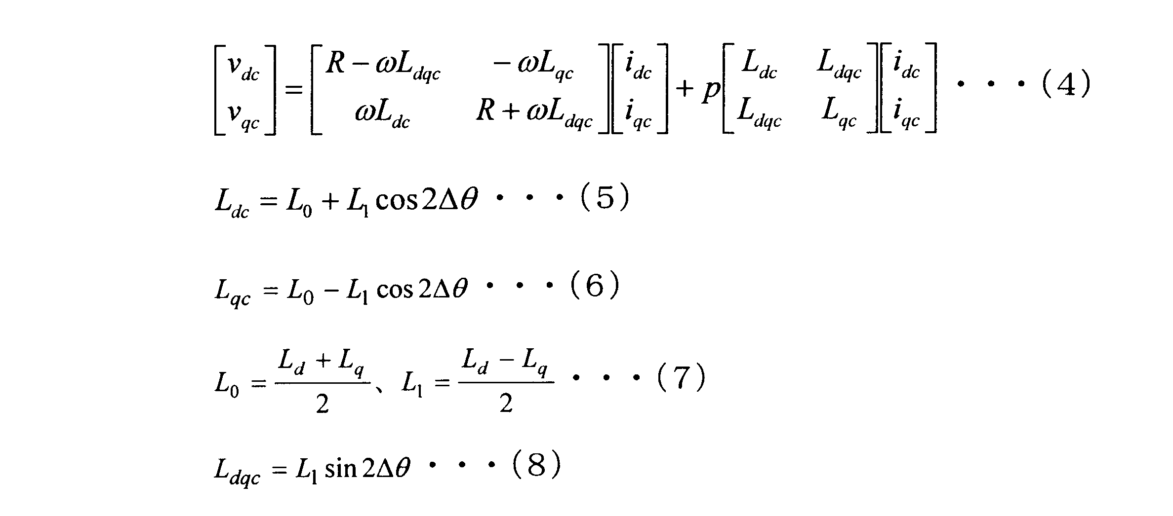
式(4)において、vdcはSynRM1に印加される電圧のdc軸成分であり、vqcはSynRM1に印加される電圧のqc軸成分である。
式(4)~(8)より、式(4)の各項に含まれるインダクタンスは、誤差Δθに依存して変化する。このため、Δθを式(3),(4)から直接求めることは難しい。そこで、式(3)を、拡張誘起電圧表現に書き換えると、式(3)は以下のように表される。

同様に、式(4)~(8)を、拡張誘起電圧表現に書き換えると、以下のように表される。

上記の式(12)で表される電圧Exを、拡張誘起電圧という。
ここで、式(10)を変形すると以下のようになる。

式(11)と式(13)とは等しいので、以下の式が成り立つ。

式(14)の各項を除算すると、以下の式が成り立つ。

さらに、式(15)の逆正接をとると、以下のようになる。

推定部28は、式(16)に基づいて、誤差Δθを算出し、誤差Δθが0となるようにPLL制御を行うことで、速度ωを推定し、推定速度ωestを算出することができる。また、推定速度ωestを積分することで、回転位相角θを推定し、推定回転位相角θestを算出することができる。
図7は、上記の方法で速度ω及び回転位相角θを推定する推定部28の構成を示す図である。図7に示すように、推定部28は、高周波検出部51と、Δθ算出部52と、PLL制御部53と、積分器54と、を備える。
高周波検出部51は、電流idc,iqcの高周波成分を検出し、電流微分項pidc,piqcを算出する。高周波検出部51が出力した電流微分項pidc,piqcは、Δθ算出部52に入力される。Δθ算出部52が算出した誤差Δθは、PLL制御部53に入力される。なお、高周波検出部51の詳細は後述する。
PLL制御部53は、誤差Δθが0になるようにPLL制御を行い、推定速度ωestを算出する。PLL制御部53が出力した推定速度ωestは、積分器54に入力される。
積分器54は、推定速度ωestを積分し、推定回転位相角θestを算出する。
加算器29は、電圧指令生成部25が出力した電圧指令vdc*と、高周波重畳部30が出力した高周波電圧vhと、を加算する。これにより、電圧指令vdc*に高周波電圧vhが重畳される。高周波電圧vhを重畳された電圧指令vdc*は、座標変換部26に入力される。
高周波重畳部30は、SynRM1の電圧振幅指令Vdqc*又はパワーPmが閾値を下回る場合、高周波電圧vhを出力する。ここでいう電圧振幅指令Vdqc*とは、電圧指令vdc*,vqc*により設定されるSynRM1の端子電圧のことであり、Vdqc*=(vdc*2+vdc*2)1/2となる。また、パワーPmとは、SynRM1の定格出力(軸出力)のことである。出力された高周波電圧vhは、加算器29により電圧指令vdc*に重畳される。以下で、電圧指令vdc*に高周波電圧vhを重畳する理由を説明する。
上述の通り、推定部28は、拡張誘起電圧Exを用いて誤差Δθを算出し、速度ω及び回転位相角θを推定する。しかしながら、SynRM1の負荷が小さい場合、式(12)の拡張誘起電圧Exは小さくなる。
ここで、図8及び図9は、従来のPMSM及びSynRMの速度に対するトルク、パワーPm、及び電圧振幅指令Vdqc*の特性を示す図である。図8は、各モータが大きなトルクを出力する重負荷時の特性を示す。図9は、各モータが小さなトルクを出力する軽負荷時の特性を示す。
図8に示すように、従来のPMSM及びSynRMは、重負荷時には十分な拡張誘起電圧Exが得られる。このため、PMSM及びSynRMを制御する制御装置は、ある速度ωnを基準として、電圧指令vdc*に対する高周波電圧vhの重畳を停止したとしても、PMSM及びSynRMを脱調させることなく、安定した制御を継続することができる。
また、図9に示すように、従来のPMSMは、軽負荷時においても、回転速度に応じた磁石電圧が発生するため、比較的大きな拡張誘起電圧Exが得られる。このため、PMSMを制御する制御装置は、ある速度ωnを基準として、電圧指令vdc*に対する高周波電圧vhの重畳を停止したとしても、PMSMを脱調させることなく制御することができる。
これに対して、図9に示すように、従来のSynRMは、軽負荷時に拡張誘起電圧Exが小さくなる。これは、上述の通りである。このため、SynRMを制御する制御装置は、ある速度ωnを基準として、電圧指令vdc*に対する高周波電圧vhの重畳を停止すると、回転位相の推定が困難となり、SynRMの脱調や、制御の不安定化を招く恐れがある。
そこで、本実施形態に係る制御装置2は、図10に示すように、SynRM1の電圧振幅指令Vdqc*又はパワーPmが閾値を下回る場合に、電圧指令vdc*に高周波電圧vhを重畳することにより、拡張誘起電圧Exを大きくし、SynRM1の制御を安定化させる。高周波電圧vhを重畳すると、式(4)のdc軸の電流微分項は、Δθが極めて小さい場合以下のようになる。

また、電流Idqが小さい場合、式(12)の拡張誘起電圧Exは、以下のようになる。

式(17)及び式(18)より、拡張誘起電圧Exは以下のようになる。

式(19)より、高周波電圧vhを重畳することにより、拡張誘起電圧Exが大きくなることがわかる。したがって、拡張誘起電圧Exを用いて回転位相角θを推定することができる。このとき、誤差Δθは、以下の式で表される。

ここで、図11は、高周波重畳部30の構成の一例を示す図である。図11の高周波重畳部30は、SynRM1のパワーPmに基づいて、高周波重畳の有無を切り替える。図11に示すように、高周波重畳部30は、判定部60を備える。
判定部60は、SynRM1のパワーPmに基づいて、高周波電圧vhを重畳するか否かを判定する。判定部60は、判定結果に応じた信号を出力する。以下では、判定部60は、拡張誘起電圧Exが大きいと判定した場合に0を出力し、拡張誘起電圧Exが小さいと判定した場合に1を出力するものとする。
高周波重畳部30は、判定部60が、拡張誘起電圧Exは大きいと判定した(0を出力した)場合、高周波電圧vhを出力しない。この場合、座標変換部26には、電圧指令vdc*が入力される。
これに対して、高周波重畳部30は、判定部60が、負荷は小さいと判定した(1を出力した)場合、高周波電圧vhを出力する。この場合、座標変換部26には、加算器29により高周波電圧vhを加算された電圧指令vdc*が入力される。なお、高周波電圧vhは、以下の式で表される。

式(20)において、Vhは振幅の設定値、fhは周波数の設定値である。
図12は、図11の判定部60の一例を示す図である。この判定部60は、上述の通り、SynRM1のパワーPmに基づいて、高周波重畳が必要か否か判定する。具体的には、判定部60は、トルク指令T*及び推定速度ωestに基づいて、SynRM1のパワーPmを算出し、パワーPmと所定の閾値Prとを比較する。判定部60は、パワーPmが閾値Prより小さい場合(Pm<Pr)、負荷が小さいと判定する。
閾値Prは、速度ω及び回転位相角θの推定精度が向上するように設定される。例えば、拡張誘起電圧Exを用いて回転位相角θを精度よく推定できる最低値をnとすると、モータ極対数を1とした場合の閾値Prに対応する拡張誘起電圧Exは以下の式で表される。

また、SynRM1のパワーPmは以下の式で表される。
したがって、式(22),(23)より、回転位相角θを精度よく推定できる拡張誘起電圧最低値nを満たす閾値Prは、以下のようになる。

判定部60は、式(24)を満たす閾値Prを逐次、或いは事前に算出し、パワーPmと比較すればよい。これにより、パワーPmが閾値Prより小さい場合に、高周波電圧vhが電圧指令vdc*に重畳される。
なお、パワーPmは、式(23)以外の代わりに、下記の数式を用いて演算してもよい。

また、高周波重畳部30は、SynRM1の電圧振幅指令Vdqc*に基づいて、高周波重畳の有無を切り替えてもよい。この場合、高周波重畳部30には、トルク指令T*及び推定速度ωestの代わりに、電圧指令vdc*,vqc*が入力される。
そして、図13に示すように、判定部60は、電圧指令vdc*,vqc*に基づいてSynRM1の電圧振幅指令Vdqc*を算出し、電圧振幅指令Vdqc*と閾値Vrとを比較し、Vdqc*<Vrの場合に負荷が小さいと判定してもよい。これにより、電圧振幅指令Vdqc*が閾値Vrより小さい場合に、高周波電圧vhが電圧指令vqc*に重畳される。
このように、負荷が小さい場合に、高周波重畳部30が高周波電圧vhを電圧指令vdc*に重畳することにより、拡張誘起電圧Exを大きくし、拡張誘起電圧Exを用いた速度ω及び回転位相角θの推定精度を向上させることができる。
ここで、推定部28の高周波検出部51の詳細について説明する。上述の通り、高周波重畳部30は、SynRM1の負荷が小さい場合、電圧指令vqc*に高周波電圧vhを重畳する。推定部28は、高周波電圧vhが重畳されていない場合、式(16)により誤差Δθを算出し、高周波電圧vhが重畳されている場合、式(20)により誤差Δθを算出する。
式(20)からわかるように、高周波電圧vhが重畳された場合、誤差Δθを算出するために、電流微分項pidc,piqcが必要となる。高周波検出部51は、この電流微分項pidc,piqcを算出する。推定部28は、高周波検出部51が算出した電流微分項pidc,piqcを式(20)に代入して、誤差Δθを算出する。
図14は、高周波検出部51の構成を示す図である。図14に示すように、高周波検出部51は、バンドパスフィルタ55と、FFT解析部56と、を備える。
バンドパスフィルタ55は、図15に示すように、入力された電流idc,iqcのうち、高周波電圧vhの周波数fhを含む所定の範囲の周波数成分を通過させ、範囲外の周波数成分を減衰させる。これにより、バンドパスフィルタ55は、電流idc,idqから、周波数fhを有する高周波電流idc′,iqc′を検出する。バンドパスフィルタ55が出力した高周波電流idc′,iqc′は、FFT解析部56に入力される。
FFT解析部56は、バンドパスフィルタ55が検出した高周波電流idc′,iqc′の振幅idc′p-p,iqc′p-pをそれぞれ算出する。FFT解析部56は、例えば、図16に示すように、高周波電流idc′,iqc′に対して、高周波電圧vhの1周期(=1/fh)中に4回サンプリングを行い、サンプリングされた4つの電流値から振幅idc′p-p,iqc′p-pをそれぞれ算出する。
高周波電流idc′,iqc′は、バンドパスフィルタ55によって余計な周波数成分を除去されている。このため、FFT解析部56は、図17に示すように、振幅idc′p-p,iqc′p-pを精度よく算出することができる。
高周波検出部51は、FFT解析部56により算出した振幅idc′p-p,iqc′p-pを、サンプリング期間dtでそれぞれ除算することにより、電流微分項pidc,piqcを算出する。
以上説明した通り、本実施形態に係るインバータ制御装置2は、SynRM1の負荷が低い場合、電圧指令vqc*に高周波電圧vhを重畳する。これにより、SynRM1の負荷が低く、鎖交磁束により生じる誘起電圧が小さい場合であっても、拡張誘起電圧Exを大きくし、拡張誘起電圧Exを用いてSynRM1の回転位相角θ及び速度ωを精度よく推定することができる。したがって、SynRM1の制御の不安定化や脱調を抑制することができる。
なお、以上の説明では、インバータ制御装置2がSynRM1の動作を制御する場合について説明したが、このインバータ制御装置2は、PMSMや、界磁磁束を二次巻線にて供給する巻線界磁式同期機の制御装置として利用することも可能である。
また、インバータ制御装置2は、高周波電圧vhを電圧指令vqc*に重畳してもよいし、高周波電流を電流指令idc*,iqc*に重畳してもよい。いずれの場合も、拡張誘起電圧Exを大きくすることができるため、上述の効果が得られる。
また、高周波重畳部30は、SynRM1の回転位相角の誤差Δθに基づいて、高周波重畳の有無を切り替えてもよい。この場合、高周波重畳部30には、トルク指令T*及び推定速度ωestの代わりに、推定部28が算出した誤差Δθが入力される。
そして、判定部60は、誤差Δθと閾値Δθrとを比較し、|Δθ|>Δθrの場合に負荷が小さいと判定してもよい。これにより、図18に示すように、誤差Δθが閾値Δθrより大きい場合に、高周波電圧vhが電圧指令vqc*に重畳される。
センサレス制御においては、回転位相角の誤差Δθは、ゼロに近づくように制御されており、誤差Δθが閾値を超える場合に高周波重畳することで、位相角誤差をゼロへ収束しやすくすることができ、SynRM1の制御の不安定化や脱調を抑制することができる。
また、インバータ制御装置2は、拡張誘起電圧Exを用いたセンサレス制御に限らず、オブザーバやPWM高調波を用いたセンサレス制御に適用することも可能である。
また、インバータ制御装置2は、電流検出器22を備えず、電流センサレスでSynRM1を制御してもよい。この場合も、同様の効果が得られる。
(第1実施形態の変形例)
次に、第1実施形態に係る高周波重畳部30の変形例について、図19~図21を参照して説明する。この高周波重畳部30は、SynRM1の負荷に応じて、重畳する高周波電圧vhの振幅Vhを変化させる。図19は、この高周波重畳部30の構成を示す図である。図19に示すように、高周波重畳部30は、振幅算出部61を更に備える。
次に、第1実施形態に係る高周波重畳部30の変形例について、図19~図21を参照して説明する。この高周波重畳部30は、SynRM1の負荷に応じて、重畳する高周波電圧vhの振幅Vhを変化させる。図19は、この高周波重畳部30の構成を示す図である。図19に示すように、高周波重畳部30は、振幅算出部61を更に備える。
振幅算出部61は、SynRM1のパワーPm又は電圧振幅指令Vdqc*に基づいて、高周波電圧vhの振幅Vhを算出する。振幅算出部61は、SynRM1のパワーPm又は電圧振幅指令Vdqc*が小さいほど、振幅Vhが大きくなるように算出する。
例えば、判定部60がSynRM1のパワーPmを用いて判定を行う場合、図19に示すように、振幅算出部61は、トルク指令T*及び推定速度ωestに基づいて、以下の式により振幅Vhを算出する。

これにより、図20に示すように、振幅Vhは、パワーPmが小さい程大きくなる。振幅Vhの値は、式(24)の関係を満たすように決定すればよい。
また、電圧振幅指令Vdqc*を用いて高周波電圧vhの振幅Vhを変更する場合、振幅算出部61は、以下の式により振幅Vhを算出してもよい。

これにより、振幅Vhは、一定の電流を通電している場合は、電圧振幅指令Vdqc*に依存せずに、速度ωに反比例して減少し、図21に示すような特性となる。
このような構成により、インバータ制御装置2は、速度ωや拡張誘起電圧Exの関係を用いて重畳する高周波電圧vhを可変することが可能となる。
なお、この高周波重畳部30は、SynRM1の負荷に応じて高周波電流vhの周波数fhを変更させてもよい。また、高周波重畳部30は、パワーPmや電圧振幅指令Vdqc*に限らず、推定速度ωestやトルク指令T*に応じて、振幅Vhを変化させてもよい。
(第2実施形態)
次に、第2実施形態に係るインバータ制御装置2について、図22~図26を参照して説明する。本実施形態に係るインバータ制御装置2は、回転位相角θ及び速度ωの推定方法を2種類利用し、SynRM1の負荷に応じて、これらの推定方法を切替える。
次に、第2実施形態に係るインバータ制御装置2について、図22~図26を参照して説明する。本実施形態に係るインバータ制御装置2は、回転位相角θ及び速度ωの推定方法を2種類利用し、SynRM1の負荷に応じて、これらの推定方法を切替える。
図22は本実施形態に係るモータ駆動システムの構成を示す図である。図22に示すように、本実施形態に係るインバータ制御装置2は、制御方式切替え部70を更に備える。以下、第1実施形態との相違点について説明する。
電圧指令生成部25は、図23に示すように、電圧指令vdc*,vqc*と共に、電圧ACRdを出力する。電圧指令生成部25が出力した電圧ACRdは、推定部28に入力される。
制御方式切替え部70は、SynRM1の電圧振幅指令Vdqc*又はパワーPmに応じて2値の制御切替え信号を出力する。本実施形態では、この制御切替え信号によって、回転位相角θ及び速度ωの推定方法などの制御方式が切替えられる。以下では、制御方式切替え部70は、電圧振幅指令Vdqc*又はパワーPmが小さい場合に0を出力し、電圧振幅指令Vdqc*又はパワーPmが大きい場合に1を出力するものとする。
制御方式切替え部70は、図24に示すように、電圧指令vdc*,vqc*に基づいてSynRM1の電圧振幅指令Vdqc*を算出し、電圧振幅指令Vdqc*と閾値Vrとを比較し、Vdqc*<Vrの場合に負荷が小さいと判定してもよい。
また、制御方式切替え部70は、トルク指令T*及び推定速度ωestに基づいて、SynRM1のパワーPmを算出し、パワーPmと所定の閾値Prとを比較し、Pm<Prの場合に負荷が小さいと判定してもよい。
さらに、制御方式切替え部70は、推定速度ωestと所定の閾値ωrとを比較し、ωest<ωrの場合に高周波電圧vhを重畳する必要があると判定してもよい。
高周波重畳部30は、制御方式切替え部70から制御切替え信号を入力される。高周波重畳部30は、制御切替え信号として0を入力された場合、高周波電圧vhを出力し、制御切替え信号として1を入力された場合、高周波電圧vhを出力しない。高周波重畳部30が出力した高周波電圧vhは、推定部28及び加算器29に入力される。
加算器29は、電圧指令vdc*と高周波電圧vhとを加算し、座標変換部26に入力する。これにより、高周波電圧vhが電圧指令vdc*に重畳される。
推定部28は、図25に示すように、PLL制御部53と、積分器54と、第1推定部57と、第2推定部58と、スイッチ59と、を備える。第1推定部57及び第2推定部58は、それぞれ異なる方法で誤差Δθを算出する。
第1推定部57は、高周波電圧vhと電流idcとに基づいて、誤差Δθを算出する。電圧指令vdc*に高周波電圧vhが重畳された場合、電流微分項pidcは以下の式で表される。

誤差Δθが十分に小さい場合、式(28)より、誤差Δθは以下の式で表される。

第1推定部57は、式(29)に基づいて、誤差Δθを算出する。
第2推定部58は、PI制御器41が出力した電圧ACRdと、フィードフォワード電圧Vd_FF,Vq_FFと、の関係を用いて誤差Δθを算出する。具体的には、第2推定部58は、電流idc,iqc及び電圧ACRdに基づいて、誤差Δθを算出する。
誤差Δθが生じる場合、式(2)より、フィードフォワード電圧Vd_FF,Vq_FFは、以下の式で表される。

ここで、式(30)のdc軸成分に着目すると、以下の式が成り立つ。

誤差Δθが十分に小さい場合、式(31)より、誤差Δθは以下の式で表される。

第2推定部58は、式(32)に基づいて、誤差Δθを算出する。
スイッチ59は、PLL制御部53に入力される誤差Δθを、制御切替え信号に応じて切替える。スイッチ59は、制御切替え信号として0を入力された場合、第1推定部57が出力した誤差ΔθをPLL制御部53に入力する。スイッチ59は、制御切替え信号として1を入力された場合、第1推定部58が出力した誤差ΔθをPLL制御部53に入力する。
PLL制御部53は、誤差Δθに対してPLL制御を行い、推定速度ωestを算出する。積分器54は、推定速度ωestを積分し、推定回転位相角θestを算出する。
以上説明した通り、本実施形態に係るインバータ制御装置2は、図26に示すように、高周波電圧vhを重畳することで発生する高調波電流を用いて回転位相を推定する第1の制御方式と、鎖交磁束による電圧を用いて回転位相を推定する第2の制御方式と、の2種類の制御方式を用いてSynRM1を制御する。
第1の制御方式では、インバータ制御装置2は、電圧指令vdc*に高周波電圧vhを重畳し、高周波電圧vhが重畳された電圧指令vdc*に基づいて誤差Δθを算出し、この誤差Δに基づいて回転位相角θ及び速度ωを推定する。これにより、インバータ制御装置2は、拡張誘起電圧Exを大きくし、回転位相角θ及び速度ωの推定精度を向上させることができる。
また、第2の制御方式では、インバータ制御装置2は、電圧指令vdc*に高周波電圧vhを重畳せずに、回転位相角θ及び速度ωを推定する。これにより、インバータ制御装置2は、トルクリプルやそれに起因した騒音、ノイズ、及び高周波損失を低減することができる。
なお、第2推定部58による誤差Δθの算出方法として、高周波電圧vhを用いない任意の方法を選択することができる。例えば、第2推定部58は、オブザーバや電圧ACRd,ACRqを用いて誤差Δθを算出してもよい。
また、制御方式切替え部70は、ヒステリシス動作により、制御切替え信号が頻繁に変更されないように構成されてもよい。
なお、本発明は上記各実施形態そのままに限定されるものではなく、実施段階ではその要旨を逸脱しない範囲で構成要素を変形して具体化できる。また、上記各実施形態に開示されている複数の構成要素を適宜組み合わせることによって種々の発明を形成できる。また例えば、各実施形態に示される全構成要素からいくつかの構成要素を削除した構成も考えられる。さらに、異なる実施形態に記載した構成要素を適宜組み合わせてもよい。
1:モータ(SynRM)、2:インバータ制御装置、21:インバータ主回路、22:電流検出器、23:座標変換部、24:電流指令生成部、25:電圧指令生成部、26:座標変換部、27:PWM変調器、28:速度・回転位相角推定部、29:加算器、30:高周波重畳部、31:インダクタンステーブル、32:電流位相角テーブル、41:PI制御器、42:フィードフォワード指令生成部、43,44:加算器、51:高周波検出部、52:Δθ算出部、53:PLL制御部、54:積分器、55:バンドパスフィルタ、56:FFT解析部、57:第1推定部、58:第2推定部、59:スイッチ、60:判定部、61:振幅算出部、70:制御方式切替え部
Claims (12)
- 所定の回転駆動対象と電気的に接続可能なインバータ主回路と、
電流指令を生成する電流指令生成部と、
前記インバータ主回路から出力される電流が、前記電流指令と等しくなる電圧指令を生成する電圧指令生成部と、
前記回転駆動対象の推定回転位相角を算出する推定部と、
前記回転駆動対象の特徴量と閾値との関係に応じて、前記電流指令又は前記電圧指令に高周波を重畳する高周波重畳部と、
を備えるインバータ制御装置。 - 前記特徴量は、前記回転駆動対象のパワーである
請求項1に記載のインバータ制御装置。 - 前記特徴量は、前記回転駆動対象への電圧振幅指令である
請求項1に記載のインバータ制御装置。 - 前記高周波重畳部は、前記パワーが所定の閾値より小さいとき、前記高周波を重畳する
請求項2に記載のインバータ制御装置。 - 前記高周波重畳部は、前記電圧振幅指令が所定の閾値より小さいとき、前記高周波を重畳する
請求項3に記載のインバータ制御装置。 - 前記高周波重畳部は、前記推定回転位相角の誤差が所定の閾値より大きいとき、前記高周波を重畳する
請求項1乃至請求項5のいずれか1項に記載のインバータ制御装置。 - 前記高周波重畳部は、前記特徴量の大きさに応じて、前記高周波の振幅を変化させる
請求項1乃至請求項6のいずれか1項に記載のインバータ制御装置。 - 前記推定部は、拡張誘起電圧を用いて前記推定回転位相角を算出する
請求項1乃至請求項7のいずれか1項に記載のインバータ制御装置。 - 前記推定部は、
前記高周波に基づいて前記推定回転位相角を算出する第1推定部と、
前記第1推定部と異なる方法で前記推定回転位相角を算出する第2推定部と、
を備える請求項1乃至請求項8のいずれか1項に記載のインバータ制御装置。 - 前記回転駆動対象のパワーが所定の閾値より小さいとき、前記第1推定部が算出した前記推定回転位相角を用いて制御する
請求項9に記載のインバータ制御装置。 - 前記回転駆動対象への電圧振幅指令が所定の閾値より小さいとき、前記第1推定部が算出した前記推定回転位相角を用いて制御する
請求項9に記載のインバータ制御装置。 - モータと、
前記モータに接続されるインバータ主回路と、
電流指令を生成する電流指令生成部と、
前記インバータ主回路から出力される電流が、前記電流指令と等しくなる電圧指令を生成する電圧指令生成部と、
前記モータの推定回転位相角を算出する推定部と、
前記モータの特徴量と閾値との関係に応じて、前記電流指令又は前記電圧指令に高周波を重畳する高周波重畳部と、
を備えるモータ駆動システム。
Priority Applications (4)
| Application Number | Priority Date | Filing Date | Title |
|---|---|---|---|
| EP15880129.0A EP3252942A1 (en) | 2015-01-28 | 2015-12-09 | Inverter control device and motor drive system |
| CN201580058309.9A CN107078675A (zh) | 2015-01-28 | 2015-12-09 | 逆变器控制装置以及电机驱动系统 |
| JP2016571799A JPWO2016121237A1 (ja) | 2015-01-28 | 2015-12-09 | インバータ制御装置及びモータ駆動システム |
| US15/606,663 US20170264227A1 (en) | 2015-01-28 | 2017-05-26 | Inverter control device and motor drive system |
Applications Claiming Priority (2)
| Application Number | Priority Date | Filing Date | Title |
|---|---|---|---|
| JP2015-014734 | 2015-01-28 | ||
| JP2015014734 | 2015-01-28 |
Related Child Applications (1)
| Application Number | Title | Priority Date | Filing Date |
|---|---|---|---|
| US15/606,663 Continuation US20170264227A1 (en) | 2015-01-28 | 2017-05-26 | Inverter control device and motor drive system |
Publications (1)
| Publication Number | Publication Date |
|---|---|
| WO2016121237A1 true WO2016121237A1 (ja) | 2016-08-04 |
Family
ID=56542871
Family Applications (1)
| Application Number | Title | Priority Date | Filing Date |
|---|---|---|---|
| PCT/JP2015/084540 Ceased WO2016121237A1 (ja) | 2015-01-28 | 2015-12-09 | インバータ制御装置及びモータ駆動システム |
Country Status (5)
| Country | Link |
|---|---|
| US (1) | US20170264227A1 (ja) |
| EP (1) | EP3252942A1 (ja) |
| JP (1) | JPWO2016121237A1 (ja) |
| CN (1) | CN107078675A (ja) |
| WO (1) | WO2016121237A1 (ja) |
Cited By (8)
| Publication number | Priority date | Publication date | Assignee | Title |
|---|---|---|---|---|
| WO2018043502A1 (ja) * | 2016-09-05 | 2018-03-08 | 東芝インフラシステムズ株式会社 | インバータ制御装置および電動機駆動システム |
| CN109690935A (zh) * | 2016-09-05 | 2019-04-26 | 株式会社东芝 | 逆变器控制装置以及马达驱动系统 |
| WO2019138692A1 (ja) * | 2018-01-12 | 2019-07-18 | 三菱電機株式会社 | 回転機の制御装置 |
| EP3509207A4 (en) * | 2016-09-05 | 2020-04-22 | Toshiba Infrastructure Systems & Solutions Corporation | INVERTER CONTROL DEVICE AND ELECTRIC MOTOR DRIVE SYSTEM |
| KR20200103325A (ko) * | 2019-02-25 | 2020-09-02 | 영남대학교 산학협력단 | 전류벡터에 기반한 속도 센서리스 모터 제어 시스템 및 풍력 발전 시스템 |
| JPWO2023223436A1 (ja) * | 2022-05-17 | 2023-11-23 | ||
| JP2024072014A (ja) * | 2022-11-15 | 2024-05-27 | 株式会社豊田自動織機 | 電動機 |
| JP2024072015A (ja) * | 2022-11-15 | 2024-05-27 | 株式会社豊田自動織機 | 電動機 |
Families Citing this family (7)
| Publication number | Priority date | Publication date | Assignee | Title |
|---|---|---|---|---|
| EP3460984A1 (de) * | 2017-09-22 | 2019-03-27 | Siemens Aktiengesellschaft | Überwachungseinrichtung für eine reluktanzmaschine und verfahren zur überwachung |
| JP6755845B2 (ja) * | 2017-09-26 | 2020-09-16 | 株式会社東芝 | モータ駆動システム |
| CN108574438A (zh) * | 2018-04-02 | 2018-09-25 | 江苏大学 | 一种飞跨电容开绕组三相永磁同步电机的逆变器开路混合调制容错控制方法 |
| DE102020122099A1 (de) * | 2020-09-04 | 2022-03-10 | Schaeffler Technologies AG & Co. KG | Verfahren zur Modulation der Drehmomentwelligkeit und/oder der Radialkraft einer drehstrombetriebenen elektrischen Maschine |
| DE102021205649A1 (de) | 2021-06-02 | 2022-12-08 | Volkswagen Aktiengesellschaft | Verfahren und Vorrichtung zum Regeln einer elektrischen Maschine |
| US11848629B1 (en) * | 2022-05-26 | 2023-12-19 | GM Global Technology Operations LLC | Method and apparatus for electric motor control |
| DE102023109006B4 (de) * | 2023-04-11 | 2024-10-24 | Schaeffler Technologies AG & Co. KG | Verfahren zur bestimmung der rotorlage eines ec-motors |
Citations (4)
| Publication number | Priority date | Publication date | Assignee | Title |
|---|---|---|---|---|
| JP2007185080A (ja) * | 2006-01-07 | 2007-07-19 | C & S Kokusai Kenkyusho:Kk | 交流電動機の回転子位相推定装置 |
| WO2010073865A1 (ja) * | 2008-12-24 | 2010-07-01 | アイシン・エィ・ダブリュ株式会社 | センサレス電動機制御装置 |
| JP2014039414A (ja) * | 2012-08-17 | 2014-02-27 | Yaskawa Electric Corp | モータ制御装置 |
| WO2014157628A1 (ja) * | 2013-03-28 | 2014-10-02 | アイシン・エィ・ダブリュ株式会社 | 回転電機制御装置 |
Family Cites Families (6)
| Publication number | Priority date | Publication date | Assignee | Title |
|---|---|---|---|---|
| WO2009024835A1 (en) * | 2007-08-20 | 2009-02-26 | Freescale Semiconductor, Inc. | Motor controller for determining a position of a rotor of an ac motor, ac motor system, and method of determining a position of a rotor of an ac motor |
| JP4687846B2 (ja) * | 2001-03-26 | 2011-05-25 | 株式会社安川電機 | 同期電動機の磁極位置推定方法および制御装置 |
| US7932692B2 (en) * | 2006-11-13 | 2011-04-26 | Denso Corporation | Control system for rotary electric machine with salient structure |
| JP5435252B2 (ja) * | 2008-01-30 | 2014-03-05 | 株式会社ジェイテクト | 車両用操舵装置 |
| JP5321614B2 (ja) * | 2011-02-28 | 2013-10-23 | 株式会社デンソー | 回転機の制御装置 |
| JP5652664B2 (ja) * | 2011-10-21 | 2015-01-14 | アイシン・エィ・ダブリュ株式会社 | 回転電機制御装置 |
-
2015
- 2015-12-09 WO PCT/JP2015/084540 patent/WO2016121237A1/ja not_active Ceased
- 2015-12-09 CN CN201580058309.9A patent/CN107078675A/zh not_active Withdrawn
- 2015-12-09 EP EP15880129.0A patent/EP3252942A1/en not_active Withdrawn
- 2015-12-09 JP JP2016571799A patent/JPWO2016121237A1/ja not_active Withdrawn
-
2017
- 2017-05-26 US US15/606,663 patent/US20170264227A1/en not_active Abandoned
Patent Citations (4)
| Publication number | Priority date | Publication date | Assignee | Title |
|---|---|---|---|---|
| JP2007185080A (ja) * | 2006-01-07 | 2007-07-19 | C & S Kokusai Kenkyusho:Kk | 交流電動機の回転子位相推定装置 |
| WO2010073865A1 (ja) * | 2008-12-24 | 2010-07-01 | アイシン・エィ・ダブリュ株式会社 | センサレス電動機制御装置 |
| JP2014039414A (ja) * | 2012-08-17 | 2014-02-27 | Yaskawa Electric Corp | モータ制御装置 |
| WO2014157628A1 (ja) * | 2013-03-28 | 2014-10-02 | アイシン・エィ・ダブリュ株式会社 | 回転電機制御装置 |
Cited By (20)
| Publication number | Priority date | Publication date | Assignee | Title |
|---|---|---|---|---|
| US10833613B2 (en) | 2016-09-05 | 2020-11-10 | Kabushiki Kaisha Toshiba | Inverter control apparatus and motor drive system |
| JP2018042324A (ja) * | 2016-09-05 | 2018-03-15 | 東芝インフラシステムズ株式会社 | インバータ制御装置および電動機駆動システム |
| CN109690935A (zh) * | 2016-09-05 | 2019-04-26 | 株式会社东芝 | 逆变器控制装置以及马达驱动系统 |
| CN109874396A (zh) * | 2016-09-05 | 2019-06-11 | 东芝基础设施系统株式会社 | 逆变器控制装置以及电动机驱动系统 |
| CN109874396B (zh) * | 2016-09-05 | 2022-10-28 | 东芝基础设施系统株式会社 | 逆变器控制装置以及电动机驱动系统 |
| EP3509211A4 (en) * | 2016-09-05 | 2020-04-15 | Kabushiki Kaisha Toshiba | CONVERTER CONTROL DEVICE AND DRIVE SYSTEM |
| EP3509207A4 (en) * | 2016-09-05 | 2020-04-22 | Toshiba Infrastructure Systems & Solutions Corporation | INVERTER CONTROL DEVICE AND ELECTRIC MOTOR DRIVE SYSTEM |
| CN109690935B (zh) * | 2016-09-05 | 2022-08-30 | 株式会社东芝 | 逆变器控制装置以及马达驱动系统 |
| WO2018043502A1 (ja) * | 2016-09-05 | 2018-03-08 | 東芝インフラシステムズ株式会社 | インバータ制御装置および電動機駆動システム |
| US10742151B2 (en) | 2016-09-05 | 2020-08-11 | Toshiba Infrastructure Systems & Solutions Corporation | Inverter control device and motor drive system |
| US11223313B2 (en) | 2016-09-05 | 2022-01-11 | Toshiba Infrastructure Systems & Solutions Corporation | Inverter control device and motor drive system |
| JPWO2019138692A1 (ja) * | 2018-01-12 | 2020-07-02 | 三菱電機株式会社 | 回転機の制御装置 |
| WO2019138692A1 (ja) * | 2018-01-12 | 2019-07-18 | 三菱電機株式会社 | 回転機の制御装置 |
| KR102262010B1 (ko) * | 2019-02-25 | 2021-06-09 | 영남대학교 산학협력단 | 전류벡터에 기반한 속도 센서리스 모터 제어 시스템 및 풍력 발전 시스템 |
| KR20200103325A (ko) * | 2019-02-25 | 2020-09-02 | 영남대학교 산학협력단 | 전류벡터에 기반한 속도 센서리스 모터 제어 시스템 및 풍력 발전 시스템 |
| JPWO2023223436A1 (ja) * | 2022-05-17 | 2023-11-23 | ||
| WO2023223436A1 (ja) * | 2022-05-17 | 2023-11-23 | 三菱電機株式会社 | 回転機の制御装置 |
| JP7599617B2 (ja) | 2022-05-17 | 2024-12-13 | 三菱電機株式会社 | 回転機の制御装置 |
| JP2024072014A (ja) * | 2022-11-15 | 2024-05-27 | 株式会社豊田自動織機 | 電動機 |
| JP2024072015A (ja) * | 2022-11-15 | 2024-05-27 | 株式会社豊田自動織機 | 電動機 |
Also Published As
| Publication number | Publication date |
|---|---|
| US20170264227A1 (en) | 2017-09-14 |
| EP3252942A1 (en) | 2017-12-06 |
| JPWO2016121237A1 (ja) | 2017-08-24 |
| CN107078675A (zh) | 2017-08-18 |
Similar Documents
| Publication | Publication Date | Title |
|---|---|---|
| WO2016121237A1 (ja) | インバータ制御装置及びモータ駆動システム | |
| TWI654827B (zh) | 換流器控制裝置及馬達驅動系統 | |
| JP6367332B2 (ja) | インバータ制御装置及びモータ駆動システム | |
| CN103595326B (zh) | 电机控制装置和电机控制方法 | |
| JP4687846B2 (ja) | 同期電動機の磁極位置推定方法および制御装置 | |
| US9531313B2 (en) | Apparatus for controlling controlled variable of rotary machine to command value | |
| CN107710594B (zh) | 交流旋转电机的控制装置及电动助力转向的控制装置 | |
| JP5098439B2 (ja) | 永久磁石同期電動機のセンサレス制御装置 | |
| KR102409792B1 (ko) | 영구 자석 동기 전동기의 제어 장치, 마이크로 컴퓨터, 전동기 시스템 및 영구 자석 동기 전동기의 운전 방법 | |
| KR20080071055A (ko) | 교류 회전기의 제어 장치 및 이 제어 장치를 사용한 교류회전기의 전기적 정수 측정 방법 | |
| JP2012055041A (ja) | ベクトル制御装置、及び電動機制御システム | |
| JP6075090B2 (ja) | モータ制御装置 | |
| JP7699908B2 (ja) | 電力変換装置 | |
| JP2008220169A (ja) | モータ制御装置 | |
| JP6422796B2 (ja) | 同期機制御装置及び駆動システム | |
| JP4583257B2 (ja) | 交流回転機の制御装置 | |
| JP5851662B1 (ja) | 交流回転機の制御装置 | |
| JP2018125955A (ja) | モータ制御装置 | |
| JP6544204B2 (ja) | モータの制御装置 | |
| JP7226211B2 (ja) | インバータ装置及びインバータ装置の制御方法 | |
| JP6089608B2 (ja) | 同期電動機の制御方法 | |
| JP6012037B2 (ja) | 電力変換装置 | |
| JP2020178508A (ja) | インバータ装置及びインバータ装置の制御方法 |
Legal Events
| Date | Code | Title | Description |
|---|---|---|---|
| 121 | Ep: the epo has been informed by wipo that ep was designated in this application |
Ref document number: 15880129 Country of ref document: EP Kind code of ref document: A1 |
|
| ENP | Entry into the national phase |
Ref document number: 2016571799 Country of ref document: JP Kind code of ref document: A |
|
| REEP | Request for entry into the european phase |
Ref document number: 2015880129 Country of ref document: EP |
|
| NENP | Non-entry into the national phase |
Ref country code: DE |