WO2016084528A1 - 車両制御装置及び車両制御方法 - Google Patents
車両制御装置及び車両制御方法 Download PDFInfo
- Publication number
- WO2016084528A1 WO2016084528A1 PCT/JP2015/079933 JP2015079933W WO2016084528A1 WO 2016084528 A1 WO2016084528 A1 WO 2016084528A1 JP 2015079933 W JP2015079933 W JP 2015079933W WO 2016084528 A1 WO2016084528 A1 WO 2016084528A1
- Authority
- WO
- WIPO (PCT)
- Prior art keywords
- vehicle
- host vehicle
- parameter
- lane
- host
- Prior art date
Links
- 238000000034 method Methods 0.000 title claims description 45
- 238000012937 correction Methods 0.000 claims abstract description 93
- 238000001514 detection method Methods 0.000 claims abstract description 33
- 230000007423 decrease Effects 0.000 claims description 23
- 230000008859 change Effects 0.000 claims description 12
- 230000008569 process Effects 0.000 description 42
- 238000013459 approach Methods 0.000 description 28
- 238000012545 processing Methods 0.000 description 16
- 230000007717 exclusion Effects 0.000 description 13
- 230000001133 acceleration Effects 0.000 description 8
- 238000003384 imaging method Methods 0.000 description 8
- 230000005540 biological transmission Effects 0.000 description 5
- 230000003247 decreasing effect Effects 0.000 description 5
- 238000012986 modification Methods 0.000 description 5
- 230000004048 modification Effects 0.000 description 5
- 238000000926 separation method Methods 0.000 description 5
- 238000010586 diagram Methods 0.000 description 4
- 230000000694 effects Effects 0.000 description 4
- 230000004043 responsiveness Effects 0.000 description 4
- 238000004891 communication Methods 0.000 description 3
- 239000000284 extract Substances 0.000 description 3
- 230000004044 response Effects 0.000 description 3
- 238000005516 engineering process Methods 0.000 description 2
- 101100215368 Dictyostelium discoideum act21 gene Proteins 0.000 description 1
- 230000003044 adaptive effect Effects 0.000 description 1
- 239000003086 colorant Substances 0.000 description 1
- 238000000605 extraction Methods 0.000 description 1
- 239000012530 fluid Substances 0.000 description 1
- 230000010365 information processing Effects 0.000 description 1
- 238000013507 mapping Methods 0.000 description 1
- 238000012544 monitoring process Methods 0.000 description 1
Images


Classifications
-
- B—PERFORMING OPERATIONS; TRANSPORTING
- B60—VEHICLES IN GENERAL
- B60W—CONJOINT CONTROL OF VEHICLE SUB-UNITS OF DIFFERENT TYPE OR DIFFERENT FUNCTION; CONTROL SYSTEMS SPECIALLY ADAPTED FOR HYBRID VEHICLES; ROAD VEHICLE DRIVE CONTROL SYSTEMS FOR PURPOSES NOT RELATED TO THE CONTROL OF A PARTICULAR SUB-UNIT
- B60W30/00—Purposes of road vehicle drive control systems not related to the control of a particular sub-unit, e.g. of systems using conjoint control of vehicle sub-units, or advanced driver assistance systems for ensuring comfort, stability and safety or drive control systems for propelling or retarding the vehicle
- B60W30/14—Adaptive cruise control
- B60W30/16—Control of distance between vehicles, e.g. keeping a distance to preceding vehicle
-
- B—PERFORMING OPERATIONS; TRANSPORTING
- B60—VEHICLES IN GENERAL
- B60R—VEHICLES, VEHICLE FITTINGS, OR VEHICLE PARTS, NOT OTHERWISE PROVIDED FOR
- B60R21/00—Arrangements or fittings on vehicles for protecting or preventing injuries to occupants or pedestrians in case of accidents or other traffic risks
-
- B—PERFORMING OPERATIONS; TRANSPORTING
- B60—VEHICLES IN GENERAL
- B60W—CONJOINT CONTROL OF VEHICLE SUB-UNITS OF DIFFERENT TYPE OR DIFFERENT FUNCTION; CONTROL SYSTEMS SPECIALLY ADAPTED FOR HYBRID VEHICLES; ROAD VEHICLE DRIVE CONTROL SYSTEMS FOR PURPOSES NOT RELATED TO THE CONTROL OF A PARTICULAR SUB-UNIT
- B60W10/00—Conjoint control of vehicle sub-units of different type or different function
- B60W10/04—Conjoint control of vehicle sub-units of different type or different function including control of propulsion units
- B60W10/06—Conjoint control of vehicle sub-units of different type or different function including control of propulsion units including control of combustion engines
-
- B—PERFORMING OPERATIONS; TRANSPORTING
- B60—VEHICLES IN GENERAL
- B60W—CONJOINT CONTROL OF VEHICLE SUB-UNITS OF DIFFERENT TYPE OR DIFFERENT FUNCTION; CONTROL SYSTEMS SPECIALLY ADAPTED FOR HYBRID VEHICLES; ROAD VEHICLE DRIVE CONTROL SYSTEMS FOR PURPOSES NOT RELATED TO THE CONTROL OF A PARTICULAR SUB-UNIT
- B60W10/00—Conjoint control of vehicle sub-units of different type or different function
- B60W10/10—Conjoint control of vehicle sub-units of different type or different function including control of change-speed gearings
-
- B—PERFORMING OPERATIONS; TRANSPORTING
- B60—VEHICLES IN GENERAL
- B60W—CONJOINT CONTROL OF VEHICLE SUB-UNITS OF DIFFERENT TYPE OR DIFFERENT FUNCTION; CONTROL SYSTEMS SPECIALLY ADAPTED FOR HYBRID VEHICLES; ROAD VEHICLE DRIVE CONTROL SYSTEMS FOR PURPOSES NOT RELATED TO THE CONTROL OF A PARTICULAR SUB-UNIT
- B60W10/00—Conjoint control of vehicle sub-units of different type or different function
- B60W10/18—Conjoint control of vehicle sub-units of different type or different function including control of braking systems
-
- B—PERFORMING OPERATIONS; TRANSPORTING
- B60—VEHICLES IN GENERAL
- B60W—CONJOINT CONTROL OF VEHICLE SUB-UNITS OF DIFFERENT TYPE OR DIFFERENT FUNCTION; CONTROL SYSTEMS SPECIALLY ADAPTED FOR HYBRID VEHICLES; ROAD VEHICLE DRIVE CONTROL SYSTEMS FOR PURPOSES NOT RELATED TO THE CONTROL OF A PARTICULAR SUB-UNIT
- B60W30/00—Purposes of road vehicle drive control systems not related to the control of a particular sub-unit, e.g. of systems using conjoint control of vehicle sub-units, or advanced driver assistance systems for ensuring comfort, stability and safety or drive control systems for propelling or retarding the vehicle
- B60W30/10—Path keeping
- B60W30/12—Lane keeping
-
- B—PERFORMING OPERATIONS; TRANSPORTING
- B60—VEHICLES IN GENERAL
- B60W—CONJOINT CONTROL OF VEHICLE SUB-UNITS OF DIFFERENT TYPE OR DIFFERENT FUNCTION; CONTROL SYSTEMS SPECIALLY ADAPTED FOR HYBRID VEHICLES; ROAD VEHICLE DRIVE CONTROL SYSTEMS FOR PURPOSES NOT RELATED TO THE CONTROL OF A PARTICULAR SUB-UNIT
- B60W30/00—Purposes of road vehicle drive control systems not related to the control of a particular sub-unit, e.g. of systems using conjoint control of vehicle sub-units, or advanced driver assistance systems for ensuring comfort, stability and safety or drive control systems for propelling or retarding the vehicle
- B60W30/14—Adaptive cruise control
-
- G—PHYSICS
- G01—MEASURING; TESTING
- G01S—RADIO DIRECTION-FINDING; RADIO NAVIGATION; DETERMINING DISTANCE OR VELOCITY BY USE OF RADIO WAVES; LOCATING OR PRESENCE-DETECTING BY USE OF THE REFLECTION OR RERADIATION OF RADIO WAVES; ANALOGOUS ARRANGEMENTS USING OTHER WAVES
- G01S13/00—Systems using the reflection or reradiation of radio waves, e.g. radar systems; Analogous systems using reflection or reradiation of waves whose nature or wavelength is irrelevant or unspecified
- G01S13/88—Radar or analogous systems specially adapted for specific applications
- G01S13/93—Radar or analogous systems specially adapted for specific applications for anti-collision purposes
- G01S13/931—Radar or analogous systems specially adapted for specific applications for anti-collision purposes of land vehicles
-
- G—PHYSICS
- G08—SIGNALLING
- G08G—TRAFFIC CONTROL SYSTEMS
- G08G1/00—Traffic control systems for road vehicles
- G08G1/16—Anti-collision systems
-
- G—PHYSICS
- G08—SIGNALLING
- G08G—TRAFFIC CONTROL SYSTEMS
- G08G1/00—Traffic control systems for road vehicles
- G08G1/16—Anti-collision systems
- G08G1/166—Anti-collision systems for active traffic, e.g. moving vehicles, pedestrians, bikes
-
- G—PHYSICS
- G08—SIGNALLING
- G08G—TRAFFIC CONTROL SYSTEMS
- G08G1/00—Traffic control systems for road vehicles
- G08G1/16—Anti-collision systems
- G08G1/167—Driving aids for lane monitoring, lane changing, e.g. blind spot detection
-
- B—PERFORMING OPERATIONS; TRANSPORTING
- B60—VEHICLES IN GENERAL
- B60T—VEHICLE BRAKE CONTROL SYSTEMS OR PARTS THEREOF; BRAKE CONTROL SYSTEMS OR PARTS THEREOF, IN GENERAL; ARRANGEMENT OF BRAKING ELEMENTS ON VEHICLES IN GENERAL; PORTABLE DEVICES FOR PREVENTING UNWANTED MOVEMENT OF VEHICLES; VEHICLE MODIFICATIONS TO FACILITATE COOLING OF BRAKES
- B60T2201/00—Particular use of vehicle brake systems; Special systems using also the brakes; Special software modules within the brake system controller
- B60T2201/08—Lane monitoring; Lane Keeping Systems
-
- B60W2420/408—
-
- B—PERFORMING OPERATIONS; TRANSPORTING
- B60—VEHICLES IN GENERAL
- B60W—CONJOINT CONTROL OF VEHICLE SUB-UNITS OF DIFFERENT TYPE OR DIFFERENT FUNCTION; CONTROL SYSTEMS SPECIALLY ADAPTED FOR HYBRID VEHICLES; ROAD VEHICLE DRIVE CONTROL SYSTEMS FOR PURPOSES NOT RELATED TO THE CONTROL OF A PARTICULAR SUB-UNIT
- B60W2520/00—Input parameters relating to overall vehicle dynamics
- B60W2520/10—Longitudinal speed
-
- B—PERFORMING OPERATIONS; TRANSPORTING
- B60—VEHICLES IN GENERAL
- B60W—CONJOINT CONTROL OF VEHICLE SUB-UNITS OF DIFFERENT TYPE OR DIFFERENT FUNCTION; CONTROL SYSTEMS SPECIALLY ADAPTED FOR HYBRID VEHICLES; ROAD VEHICLE DRIVE CONTROL SYSTEMS FOR PURPOSES NOT RELATED TO THE CONTROL OF A PARTICULAR SUB-UNIT
- B60W2540/00—Input parameters relating to occupants
- B60W2540/215—Selection or confirmation of options
-
- B—PERFORMING OPERATIONS; TRANSPORTING
- B60—VEHICLES IN GENERAL
- B60W—CONJOINT CONTROL OF VEHICLE SUB-UNITS OF DIFFERENT TYPE OR DIFFERENT FUNCTION; CONTROL SYSTEMS SPECIALLY ADAPTED FOR HYBRID VEHICLES; ROAD VEHICLE DRIVE CONTROL SYSTEMS FOR PURPOSES NOT RELATED TO THE CONTROL OF A PARTICULAR SUB-UNIT
- B60W2554/00—Input parameters relating to objects
- B60W2554/40—Dynamic objects, e.g. animals, windblown objects
- B60W2554/404—Characteristics
- B60W2554/4041—Position
-
- B—PERFORMING OPERATIONS; TRANSPORTING
- B60—VEHICLES IN GENERAL
- B60W—CONJOINT CONTROL OF VEHICLE SUB-UNITS OF DIFFERENT TYPE OR DIFFERENT FUNCTION; CONTROL SYSTEMS SPECIALLY ADAPTED FOR HYBRID VEHICLES; ROAD VEHICLE DRIVE CONTROL SYSTEMS FOR PURPOSES NOT RELATED TO THE CONTROL OF A PARTICULAR SUB-UNIT
- B60W2554/00—Input parameters relating to objects
- B60W2554/80—Spatial relation or speed relative to objects
- B60W2554/801—Lateral distance
-
- B—PERFORMING OPERATIONS; TRANSPORTING
- B60—VEHICLES IN GENERAL
- B60W—CONJOINT CONTROL OF VEHICLE SUB-UNITS OF DIFFERENT TYPE OR DIFFERENT FUNCTION; CONTROL SYSTEMS SPECIALLY ADAPTED FOR HYBRID VEHICLES; ROAD VEHICLE DRIVE CONTROL SYSTEMS FOR PURPOSES NOT RELATED TO THE CONTROL OF A PARTICULAR SUB-UNIT
- B60W2554/00—Input parameters relating to objects
- B60W2554/80—Spatial relation or speed relative to objects
- B60W2554/802—Longitudinal distance
-
- B—PERFORMING OPERATIONS; TRANSPORTING
- B60—VEHICLES IN GENERAL
- B60W—CONJOINT CONTROL OF VEHICLE SUB-UNITS OF DIFFERENT TYPE OR DIFFERENT FUNCTION; CONTROL SYSTEMS SPECIALLY ADAPTED FOR HYBRID VEHICLES; ROAD VEHICLE DRIVE CONTROL SYSTEMS FOR PURPOSES NOT RELATED TO THE CONTROL OF A PARTICULAR SUB-UNIT
- B60W2554/00—Input parameters relating to objects
- B60W2554/80—Spatial relation or speed relative to objects
- B60W2554/804—Relative longitudinal speed
Definitions
- the present disclosure relates to a vehicle control technology that is mounted on a vehicle and detects other vehicles existing in front of the vehicle.
- a millimeter wave or the like is transmitted as an exploration wave at regular intervals over a predetermined angle around the vehicle, and the position of the other vehicle is detected by receiving the reflected wave, and the own vehicle follows the detected other vehicle.
- a vehicle control apparatus that performs the above.
- This disclosure is intended to provide a vehicle control technology that can quickly determine whether another vehicle is present on the course of the host vehicle.
- the present disclosure is a vehicle control device that is mounted on a host vehicle and controls the host vehicle in accordance with the position of another vehicle existing in front of the host vehicle, in a lateral direction that is a direction orthogonal to the course of the host vehicle.
- Setting means for setting a parameter indicating the relative position of the other vehicle with respect to the own vehicle, determination means for determining whether or not the other vehicle is located on the course of the own vehicle by the parameter, Detecting means for detecting whether or not relative movement in the lateral direction has been performed in one vehicle, and correcting means for correcting parameters when it is detected that relative movement in the lateral direction has been performed; .
- the parameter is corrected when at least one of the own vehicle and the other vehicle moves in the relative lateral direction by the above configuration.
- FIG. 1 is an overall configuration diagram of the vehicle control device.
- FIG. 2 is a diagram showing a probability map of the own lane.
- FIG. 3 is a diagram illustrating an example in which the lateral movement in the approach direction is performed.
- FIG. 4 is a diagram illustrating an example in which the lateral movement in the separation direction is performed.
- FIG. 5 is a flowchart showing the processing according to the first embodiment.
- FIG. 6 is a time chart when the processing according to the first embodiment is executed.
- FIG. 7 is a flowchart showing processing according to the second embodiment.
- FIG. 8 is a flowchart showing a subroutine of the first process.
- a vehicle control device including an object detection device is mounted on a vehicle and has an ACC (Adaptive Cruise Control) function.
- the vehicle control device causes the host vehicle to follow the vehicle so that the distance between the other vehicle detected by the object detection device and the host vehicle becomes a target value of the inter-vehicle distance according to the vehicle speed. Further, the vehicle control device performs control so that the vehicle speed set as the target value is obtained when no other vehicle is detected.
- ACC Adaptive Cruise Control
- the vehicle control device includes a radar device 11, an image acquisition device 12, an inter-vehicle control ECU 13, an engine ECU 14, and a brake ECU 15.
- the inter-vehicle control ECU 13 functions as an object detection device using information acquired from the radar device 11 and the image acquisition device 12, and controls the inter-vehicle distance in cooperation with the engine ECU 14 and the brake ECU 15. To do.
- the radar device 11 and the image acquisition device 12 and the ECUs 13 to 15 are connected to each other via an in-vehicle network so that mutual communication is possible.
- An ACC switch 16 is connected to the inter-vehicle control ECU 13.
- a transmission 17, a throttle motor 18, and a throttle sensor 19 are connected to the engine ECU 14.
- a vehicle speed sensor 20 and a brake ACT (actuator) 21 are connected to the brake ECU 15.
- Each of these devices is connected by a dedicated line such as serial communication.
- the radar device 11, the image acquisition device 12, and the ECUs 13 to 15 are information processing devices equipped with a microcomputer, a wire harness interface, and the like.
- the microcomputer has a configuration including a CPU, a ROM, a RAM, an I / O port, a CAN communication device, and the like.
- the radar device 11 detects the distance, relative speed, and relative position for each of the other vehicles, and provides the detection result to the inter-vehicle control ECU 13.
- the image acquisition device 12 includes an imaging unit that captures an image of an object or the like, acquires a captured image around the host vehicle, performs predetermined processing, and provides the processing result to the inter-vehicle control ECU 13.
- the inter-vehicle control ECU 13 transmits an acceleration instruction value for instructing the acceleration of the host vehicle to the engine ECU 14 and the brake ECU 15 based on the other vehicle information transmitted from the radar device 11 and the image acquisition device 12, the current vehicle speed, the acceleration, and the like. To do.
- ACC switch 16 accepts driver's operation for ACC.
- the inter-vehicle control ECU 13 transmits an acceleration instruction value to the engine ECU 14 and the brake ECU 15.
- the driver's operation for ACC includes, for example, ON / OFF of ACC, switching between a mode for keeping the inter-vehicle distance constant and a mode for keeping the vehicle speed constant, an indication value of the vehicle speed, and the like.
- the engine ECU 14 controls the throttle motor 18 while monitoring the throttle opening detected by the throttle sensor 19. For example, the engine ECU 14 determines the throttle opening based on the acceleration instruction value received from the inter-vehicle control ECU 13 and the current vehicle speed based on table data in which the throttle opening is associated with the vehicle speed and the acceleration instruction value. Further, the engine ECU 14 determines whether or not it is necessary to change gear positions (necessity) based on the vehicle speed and the throttle opening, and if necessary, instructs the transmission 17 to change gear positions.
- the brake ECU 15 brakes the host vehicle by controlling the opening / closing and opening of the valve of the brake ACT21.
- the brake ACT 21 controls the acceleration (or deceleration) of the host vehicle by increasing, maintaining, or reducing the wheel cylinder pressure of each wheel by the pressure generated by the pump in the working fluid (for example, oil).
- the brake ECU 15 brakes the host vehicle according to the acceleration instruction value transmitted by the inter-vehicle control ECU 13.
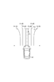
- the radar device 11 functions as first detection means for detecting the relative position of another vehicle with respect to the host vehicle.
- the radar device 11 is, for example, a radar device that uses a millimeter-wave band high-frequency signal as a transmission wave.
- the radar device 11 detects a position of an object within the detection range by setting a region within a predetermined detection angle in front of the host vehicle as a detection range. To do.
- the radar apparatus 11 includes a transmission / reception unit 11a that transmits a survey wave and receives a reflected wave by a plurality of antennas, and a distance calculation unit 11b that calculates a distance between the host vehicle and another vehicle. .
- a relative speed calculation unit 11c that calculates a relative speed between the host vehicle and the other vehicle, and an orientation calculation unit 11d that calculates an orientation of the other vehicle with respect to the host vehicle are provided.
- the distance calculation unit 11b calculates the distance between the host vehicle and the other vehicle based on the transmission time of the exploration wave and the reception time of the reflected wave.
- the relative speed calculation unit 11c calculates the relative speed based on the frequency of the reflected wave reflected by the other vehicle (frequency changed by the Doppler effect).
- the direction calculation unit 11d calculates the direction of the other vehicle based on the phase difference of the reflected waves received by the plurality of antennas.
- the radar device 11 can specify the relative position of the other vehicle with respect to the host vehicle if the position and orientation of the other vehicle can be calculated.
- the radar apparatus 11 transmits the exploration wave to the other vehicle and receives the reflected wave from the other vehicle at predetermined intervals. Further, the radar device 11 performs calculation of the reflection position, which is the position where the exploration wave is reflected, and calculation of the relative speed between the host vehicle and the other vehicle at predetermined intervals. As a result, the radar apparatus 11 transmits information including at least the reflection position (position based on the reflected wave) to the inter-vehicle control ECU 13 as the first detection information.
- the image acquisition device 12 includes an imaging unit 12a (imaging means), and the imaging unit 12a is a monocular imaging device, such as a CCD camera, a CMOS image sensor, or a near infrared camera.
- the imaging unit 12a is attached to a predetermined height in the center in the vehicle width direction of the vehicle, and images a region (detection range by the radar device 11) that extends in a range of a predetermined angle toward the front of the vehicle from an overhead viewpoint.
- the image processing unit 12b extracts feature points (feature points indicating the presence of other vehicles) in the image captured by the imaging unit 12a. Specifically, the image processing unit 12b extracts edge points based on the luminance information of the image, and performs Hough transform on the extracted edge points.
- the image acquisition device 12 captures an image and extracts feature points at each control cycle that is the same as or different from that of the radar device 11. As a result, the image acquisition device 12 transmits information including at least a feature point extraction result (a position based on the captured image of the detection range) to the inter-vehicle control ECU 13 as second detection information.
- the inter-vehicle control ECU 13 uses the own lane probability as a parameter for determining whether there is another vehicle in the own lane that is the lane in which the own vehicle is traveling for each of the other vehicles existing in the traveling direction of the own vehicle. S is used.
- the own lane probability S will be described with reference to FIG.
- the other vehicle travels over a predetermined range on the virtual plane (virtual coordinate space) located in front of the own vehicle 30 in the traveling direction.
- a probability map which is a determination area for determining whether or not it is located above, is set.
- the inter-vehicle control ECU 13 functions as a setting unit that sets a parameter indicating the relative position of the other vehicle with respect to the host vehicle 30 in the lateral direction orthogonal to the course of the host vehicle 30.
- This probability map is set within a detectable range of the radar apparatus 11.
- the own lane probability S is associated with the position (coordinates) on the probability map.
- the inter-vehicle control ECU 13 obtains the own lane probability S of the other vehicle with respect to the own vehicle 30 by mapping the relative position of the other vehicle with respect to the own vehicle 30 to the position on the coordinate space in the probability map.
- FIG. 2 shows an example of a probability map in which the own lane probabilities S of probability values 30 to 90 are associated with each other in a virtual coordinate space indicating the relative position of the other vehicle in front of the own vehicle 30. .
- the own lane probability S on the probability map is set such that the value gradually decreases from the course of the host vehicle 30 toward the lateral direction orthogonal to the course of the host vehicle 30. Furthermore, the own lane probability S is set such that the range of the corresponding position is partially enlarged as the distance from the own vehicle 30 increases. The reason for performing these settings is that the error in the position of the object detected by the radar apparatus 11 increases as the distance from the host vehicle 30 increases.
- the inter-vehicle control ECU 13 calculates the threshold Th that is a predetermined value and the calculated own vehicle probability. The value with the lane probability S is compared.
- the inter-vehicle control ECU 13 selects the other vehicle detected by the radar device 11 as the preceding vehicle used for the follow-up control of the own vehicle 30 when the value of the own lane probability S is equal to or greater than the threshold Th. .
- the inter-vehicle control ECU 13 has already selected the other vehicle detected by the radar device 11 as the preceding vehicle used for the follow-up control of the own vehicle 30 when the own lane probability S is a value less than the threshold Th. Cancel the selection of the vehicle.
- the host lane probability S is 90.
- the host lane probability S is approximately 40.
- the threshold Th is set as 50
- the other vehicle at the position P1 is selected as the preceding vehicle because the own lane probability S is equal to or higher than the threshold Th.
- the other vehicle at the position P2 is not selected as the preceding vehicle because the own lane probability S is less than the threshold Th (when the preceding vehicle is selected, the selection is canceled).
- the specific probability value of the own lane probability S is shown in the probability map of FIG. 2, this is merely an example. That is, the probability map is such that the other vehicle is selected as the preceding vehicle as the lateral relative position of the other vehicle with respect to the own vehicle 30 moves toward a position near the course of the own vehicle 30 (near the center of the own lane).
- the own lane probability S may be set.
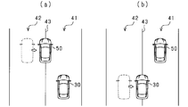
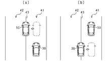
- FIG. 3 shows an example in which the own lane probability S increases as the driving behavior of the vehicle changes.
- FIG. 4 shows an example in which the own lane probability S decreases.
- FIG. 3B the host vehicle 30 traveling in the second lane 42 while the other vehicle 50 is traveling in the first lane 41, and the other vehicle 50 traveling in the first lane 41 across the white line 43.
- An example in the case of entering the rear of the vehicle and changing lanes is shown.
- the host vehicle 30 enters the first lane 41 the relative position in the lateral direction between the other vehicle 50 traveling ahead and the host vehicle 30 approaches. Therefore, as the host vehicle 30 moves, the host lane probability S increases.
- FIG. 4A while the host vehicle 30 is traveling in the first lane 41, the other vehicle 50 traveling in front of the host vehicle 30 in the first lane 41 crosses the white line 43 from the first lane 41.
- An example in the case of leaving and changing lanes is shown. In such a case, since the other vehicle 50 is moving in a direction away from the front position in the traveling direction of the own vehicle 30, the own lane probability S of the other vehicle 50 is reduced along with the movement.
- FIG. 4B shows that the own vehicle 30 traveling behind the other vehicle 50 in the first lane 41 leaves the first lane 41 across the white line 43 while the other vehicle 50 is traveling in the first lane 41.
- An example when the lane is changed is shown.
- the host vehicle 30 enters the first lane 41 the relative position in the lateral direction with respect to the other vehicle 50 traveling ahead is separated. Accordingly, as the host vehicle 30 moves, the host lane probability S decreases.
- the own lane probability S gradually increases as the own vehicle 30 or the other vehicle 50 moves in the lateral direction.
- the own lane probability S gradually decreases as the host vehicle 30 or the other vehicle 50 moves in the lateral direction. Therefore, selection and cancellation of the preceding vehicle in the case of the lane change shown in FIGS. 3 and 4 cannot be performed at the beginning of the movement of the vehicle. Thereby, the responsiveness of selection and cancellation of the preceding vehicle is lowered.
- relative lateral movement in the approach direction of the host vehicle 30 and the other vehicle 50 (hereinafter referred to as “relative lateral movement”). ”) Is detected, a correction value N indicating the approach probability is added to the own lane probability S calculated based on the probability map. That is, in the present embodiment, the own lane probability S is corrected when the vehicle performs a relative lateral movement in the approach direction. At this time, the relative lateral movement in the approach direction is detected using a change in the position of the other vehicle 50 detected by the radar device 11.
- the inter-vehicle control ECU 13 calculates the movement amount of the relative lateral movement of the other vehicle 50 relative to the host vehicle 30 (the relative lateral movement amount) based on the detection value of the radar device 11. Monitor.
- the inter-vehicle control ECU 13 determines whether or not the vehicle has made a relative lateral movement on the condition that the amount of movement per hour has exceeded a predetermined value. Further, the inter-vehicle control ECU 13 adds the correction value N to the own lane probability S (corrects the own lane probability S) while the vehicle continues to move laterally and at the end of the lateral movement. Do different processing.
- the correction value N is set to the first predetermined value N1, and thereafter, when the lateral movement is completed, the correction value N is gradually decreased from the first predetermined value N1.
- the lateral movement of the other vehicle 50 is determined.
- the own lane probability S at the end position is less than the threshold Th. Therefore, in this embodiment, when the lateral movement of the vehicle is finished, the correction value N added to the own lane probability S is gradually decreased so that the selection as the preceding vehicle is not immediately released.
- the calculation is based on the probability map.
- a correction value N indicating the departure probability is added to the own lane probability S (the own lane probability S is corrected).
- the own lane probability S shifts in the decreasing direction, and therefore the correction value N added to the own lane probability S is set to a negative value.
- the relative lateral position between the own vehicle 30 and the other vehicle 50 is sufficiently different. (Meaning that there is a sufficient distance between the own vehicle 30 and the other vehicle 50 in the lateral direction). In such a case, when the lateral movement of the other vehicle 50 is detected, if the other vehicle 50 is immediately selected as the preceding vehicle, the selection is likely to be an erroneous selection. Further, when the value of the own lane probability S is sufficiently larger than the threshold Th, it means that the other vehicle 50 is located on the course of the own vehicle 30.
- the first predetermined value N1 set as the correction value N of the own lane probability S may be a value lower than the threshold Th (for example, a value of about 20 to 30 when the threshold Th is 50). . And while lateral movement continues, selection and exclusion as a preceding vehicle should just be performed.
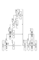
- FIG. 5 is a flowchart showing a process executed by the inter-vehicle control ECU 13 according to the present embodiment. This process is performed for all the other vehicles 50 detected by the radar apparatus 11, and is repeatedly executed at a predetermined control cycle.
- the correction value N of the own lane probability S is maintained at the first predetermined value N1.
- the inter-vehicle control ECU 13 determines that the lateral movement is not performed in the approach direction (S101: NO), whether or not the relative lateral movement in the separation direction of the host vehicle 30 and the other vehicle 50 is performed. Is determined (S103). In the process of S103 (detection of the lateral movement of the vehicle), the movement amount of the lateral movement of the other vehicle 50 relative to the host vehicle 30 is monitored as in the process of S101, and the movement amount per time exceeds a predetermined value. It is determined whether or not a relative lateral movement in the withdrawal direction has been performed.
- the reason for performing the process of S105 is after the period in which the correction value N of the own lane probability S is determined to be a value greater than 0 after detecting a lateral movement in the approach direction. This is because it corresponds to the gradual decrease period of the correction value N.
- the inter-vehicle control ECU 13 determines that the correction value N of the own lane probability S is not a value larger than 0 (S105: NO), it determines whether the correction value N of the own lane probability S is a value smaller than 0. Determination is made (S107).
- the reason for performing the process of S108 (increasing the correction value N) is after the period in which it is determined that the correction value N of the own lane probability S is a value smaller than 0 is detected as a lateral movement in the departure direction. This is because it corresponds to the gradual decrease period of the correction value N.
- the inter-vehicle control ECU 13 adds the correction value N to the own lane probability S calculated using the probability map and corrects the corrected own lane probability (hereinafter referred to as the following lane probability).
- the correction value N of the own lane probability S is a positive value in the gradual decrease period of the correction value N performed after the vehicle has moved laterally in the approach direction, and thus the corrected probability S * is the own lane probability S. (S *> S).
- the corrected probability S * is greater than the own lane probability S. Is also a small value (S * ⁇ S).
- the inter-vehicle control ECU 13 compares the calculated corrected probability S * with the threshold Th and determines whether or not the corrected probability S * is equal to or greater than the threshold Th (S110). When it is determined that the corrected probability S * is equal to or greater than the threshold value Th (S110: YES), the inter-vehicle control ECU 13 sets the other vehicle 50 (selection target vehicle) corresponding to the compared corrected probability S * as a preceding vehicle. Select (S111). In the process of S111 (selection of the preceding vehicle), if the selection target vehicle has already been selected as the preceding vehicle, the selection state of the preceding vehicle is maintained.
- the inter-vehicle control ECU 13 precedes the other vehicle 50 (exclusion target vehicle) corresponding to the compared corrected probability S *. Excluded from the vehicle (S112).
- the process of S112 inclusion from the preceding vehicle
- the exclusion target vehicle is not selected as the preceding vehicle
- the state where the exclusion target vehicle is not selected as the preceding vehicle is maintained. Therefore, in the process of S112, when the exclusion target vehicle is selected as the preceding vehicle, a process of excluding the exclusion target vehicle from the preceding vehicle is performed.
- the inter-vehicle control ECU 13 ends the series of processes.
- the inter-vehicle control ECU 13 performs the processing of S101 and S103, thereby detecting whether or not relative lateral movement has been performed in at least one of the host vehicle 30 and the other vehicle 50. Function.
- the inter-vehicle control ECU 13 executes the processes of S102 and S104 to S109, so that when the relative lateral movement is performed, the parameter (the own vehicle It functions as a correction means for correcting the lane probability S).
- the inter-vehicle control ECU 13 functions as a determination unit that determines whether or not the other vehicle 50 is positioned on the course of the host vehicle 30 based on the parameter (own lane probability S) by executing the process of S110.
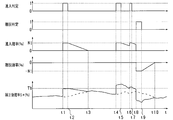
- FIG. 6 shows a time chart showing an example when the inter-vehicle control ECU 13 according to the present embodiment executes the process.
- the corrected probability S * is indicated by a solid line
- the own lane probability S before correction is indicated by a broken line.
- the inter-vehicle control ECU 13 detects the relative lateral movement of the host vehicle 30 or the other vehicle 50 in the approach direction at time t1 and makes an entry determination.
- the first predetermined value N1 is set as the correction value N indicating the approach probability.
- the inter-vehicle control ECU 13 adds the correction value N to the own lane probability S to calculate a corrected probability S *.
- the own lane probability S before correction is a relatively small value, and the corrected probability S * Is less than the threshold Th. Therefore, the other vehicle 50 is not selected as the preceding vehicle.
- the inter-vehicle control ECU 13 gradually decreases the correction value N indicating the approach probability from time t2 to time t3 (gradually decreases the correction value N).
- the inter-vehicle control ECU 13 performs the entry determination again at time t4.
- the own lane probability S indicates a value larger than that at time t1, so that the correction value N is added to exceed the threshold Th.
- the inter-vehicle control ECU 13 selects the other vehicle 50 as the preceding vehicle.
- This entry determination is continued until time t5, and the entry determination ends at time t5.
- the inter-vehicle control ECU 13 gradually decreases the correction value N indicating the approach probability (the correction value N is gradually decreased).
- the inter-vehicle control ECU 13 sets the correction value N indicating the entry probability to the first predetermined value N1. After this entry determination continues until time t7, the inter-vehicle control ECU 13 performs a departure determination at time t8 during the gradual decrease period. As a result, the correction value N indicating the separation probability indicates a negative value of the first predetermined value N1. This separation determination is performed until time t9. Thereafter, the inter-vehicle control ECU 13 gradually increases the correction value N indicating the separation probability until the time t10, and makes the value of the correction value N zero.
- the vehicle control device has the following effects due to the above configuration.
- the host lane probability S (parameter) that takes a larger value as it approaches the course of the host vehicle 30.
- the own lane probability S increases or decreases with the relative lateral movement of the host vehicle 30 and the other vehicle 50.
- the own lane probability S gradually increases or decreases. Therefore, when determining whether or not the other vehicle 50 is positioned on the course of the host vehicle 30, a determination delay may occur.
- the correction value N is added to or subtracted from the own lane probability S when the relative lateral movement between the own vehicle 30 and the other vehicle 50 is detected.
- the first predetermined value N1 is set to a value smaller than the threshold value Th. Therefore, in the probability map, when the relative lateral movement is performed for the other vehicle 50 existing at a position where the own lane probability S is low, the corrected probability S * is set to the threshold Th by adding the first predetermined value N1. Can be controlled so as not to exceed immediately, and erroneous selection as a preceding vehicle can be suppressed.
- the vehicle control apparatus has the same overall configuration as that of the vehicle control apparatus according to the first embodiment, and the processing executed by the inter-vehicle control ECU 13 is partially different. Furthermore, the image acquisition device 12 according to the present embodiment detects a travel division line such as a white line drawn on the road ahead of the host vehicle 30 from the image (road image) captured by the imaging unit 12a. That is, the image acquisition device 12 according to the present embodiment functions as a second detection unit that detects a travel lane marking on the road on which the host vehicle 30 travels.
- the white line is shown as an example of a travel division line, it is not restricted to this.
- the detection target is not limited to the white line, and traveling lane markings of various colors can be the detection target.
- the running line such as a white line can be detected not only as a continuous line but also as a broken line.
- the determination as to whether or not the relative lateral movement in the approach direction or the departure direction in the vehicle has been performed is performed by determining whether or not the host vehicle 30 or the other vehicle 50 straddles the white line. .
- the reason why the relative lateral movement can be determined based on the above conditions is that the vehicle straddles the white line because the driver has performed a lane change operation (the vehicle may have changed lanes). Is high).
- Whether or not the other vehicle 50 straddles the white line is determined by determining whether or not a part of the white line detected by the image acquisition device 12 is shielded by the other vehicle 50.
- whether or not the host vehicle 30 straddles the white line is determined by determining whether or not the detected white line is located within a predetermined range near the course of the host vehicle 30.
- the vehicle control apparatus adds the correction value N to the own lane probability S when the own vehicle 30 or the other vehicle 50 straddles the white line, as in the first embodiment. S is corrected.
- a second predetermined value N2 (first predetermined value N1 ⁇ second predetermined value N2) that is larger than the first predetermined value N1 is used.
- the relative lateral movement of the vehicle in the approaching direction or the leaving direction is a method of determining whether or not the white line is crossed rather than a change in the relative positional relationship between the vehicles obtained based on the detection result of the radar device 11.
- the second predetermined value N2 used as the correction value N when the vehicle straddles the white line is set to a value larger than the first predetermined value N1.
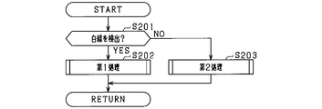
- FIG. 7 is a flowchart showing processing executed by the inter-vehicle control ECU 13 according to the present embodiment. This process is performed for all the other vehicles 50 detected by the radar apparatus 11, and is repeatedly executed at a predetermined control cycle.
- the vehicle control device first determines whether or not a white line is detected by the image acquisition device 12 (S201). As a result, when it is determined by the image acquisition device 12 that a white line has been detected (S201: YES), the vehicle control device according to the present embodiment executes the first process by the inter-vehicle control ECU 13 (S202). Specifically, the inter-vehicle control ECU 13 determines the relative lateral movement of the vehicle in the approaching direction or the leaving direction by determining whether the host vehicle 30 or the other vehicle 50 straddles the white line (first process). ).
- the inter-vehicle control ECU 13 executes the second process (S203). Specifically, the inter-vehicle control ECU 13 determines a relative lateral movement of the vehicle in the approaching direction or the leaving direction based on a change in the relative lateral position between the host vehicle 30 and the other vehicle 50 (second process). ). In the second process, the same process as the process shown in FIG. 5 in the first embodiment is executed.
- FIG. 8 is a flowchart showing a subroutine of the first process.
- the inter-vehicle control ECU 13 first determines whether or not the vehicle straddles the white line by the relative lateral movement in the approach direction by the own vehicle 30 or the other vehicle 50 (S301).
- the correction value N of the own lane probability S is maintained at the second predetermined value N2.
- the inter-vehicle control ECU 13 determines that the vehicle does not straddle the white line due to the lateral movement in the approach direction (S301: NO)
- the inter-vehicle control ECU 13 performs the relative lateral movement in the departure direction by the own vehicle 30 or the other vehicle 50. Then, it is determined whether or not the vehicle straddles the white line (S303).
- the inter-vehicle control ECU 13 reverses the sign of the second predetermined value N2 for the correction value N of the own lane probability S when it is determined that the vehicle has straddled the white line by lateral movement in the departure direction (S303: YES).
- the inter-vehicle control ECU 13 determines whether the correction value N is greater than 0 (S305). .
- the correction value N of the own lane probability S is a value larger than 0 (S305: YES)
- the reason for performing the process of S305 is that the period when the correction value N of the own lane probability S is determined to be a value greater than 0, This is because it corresponds to the gradual decrease period of the correction value N performed after it is determined that the crossing is over.
- the inter-vehicle control ECU 13 determines that the correction value N of the own lane probability S is not a value larger than 0 (S305: NO), it determines whether the correction value N of the own lane probability S is a value smaller than 0. Determination is made (S307).
- the reason for performing the process of S308 is that the vehicle is a white line due to the lateral movement in the departure direction during the period in which the correction value N of the own lane probability S is determined to be a value smaller than 0. This is because it corresponds to a gradual decrease period of the correction value N performed after it is determined that the threshold value is crossed.
- the inter-vehicle control ECU 13 adds the correction value N to the own lane probability S calculated using the probability map, and calculates the corrected probability S *.
- S * S + N
- the corrected probability S * is larger than the own lane probability S (S *> S).
- the corrected probability S * Is a value smaller than the own lane probability S (S * ⁇ S).
- the inter-vehicle control ECU 13 compares the calculated corrected probability S * with the threshold value Th, and determines whether or not the corrected probability S * is greater than or equal to the threshold value Th (S310). When it is determined that the corrected probability S * is equal to or greater than the threshold value Th (S310: YES), the inter-vehicle control ECU 13 sets the other vehicle 50 (selection target vehicle) corresponding to the compared corrected probability S * as the preceding vehicle. Select (S311). In the process of S311 (selection of preceding vehicle), if the selection target vehicle has already been selected as the preceding vehicle, the selection state of the preceding vehicle is maintained.
- the inter-vehicle control ECU 13 precedes the other vehicle 50 (exclusion target vehicle) corresponding to the compared corrected probability S *. Excluded from the vehicle (S312).
- S312 inclusion from the preceding vehicle
- the exclusion target vehicle is not selected as the preceding vehicle
- the state where the exclusion target vehicle is not selected as the preceding vehicle is maintained. Therefore, in the process of S112, when the exclusion target vehicle is selected as the preceding vehicle, a process of excluding the exclusion target vehicle from the preceding vehicle is performed.
- the inter-vehicle control ECU 13 ends the series of processes.
- the inter-vehicle control ECU 13 performs the processes of S301 and S303, so that in at least one of the own vehicle 30 and the other vehicle 50, relative lateral movement is performed based on the determination result of whether or not the white line is straddled. It functions as a detection means for detecting whether or not it has been performed.
- the inter-vehicle control ECU 13 executes the processes of S302 and S304 to S309, so that when the relative lateral movement is performed, a parameter indicating the relative position in the lateral direction of the other vehicle 50 with respect to the own vehicle 30 (the own vehicle It functions as a correction means for correcting the lane probability S).
- the inter-vehicle control ECU 13 functions as a determination unit that determines whether or not the other vehicle 50 is located on the course of the own vehicle 30 based on the parameter (own lane probability S) by executing the process of S310.
- the vehicle control apparatus according to the present embodiment has the following effects in addition to the effects exerted by the vehicle control apparatus according to the first embodiment.
- the vehicle control device when the own vehicle 30 or the other vehicle 50 straddles a travel line such as a white line, it is highly likely that the own vehicle 30 or the other vehicle 50 is changing the lane.
- a running lane marking such as a white line
- the second predetermined value N2 is added to the own lane probability S.
- the vehicle control device when a white line is detected in front of the host vehicle, relative lateral to the entering direction and the leaving direction in the vehicle based on the determination result of whether or not the vehicle straddles the white line. Judge the movement. On the other hand, when the white line is not detected in front of the host vehicle, the determination of the relative lateral movement in the approach direction and the departure direction in the vehicle is performed based on the detection result of the relative lateral position between the vehicles. . Thereby, in the vehicle control device according to the present embodiment, it is possible to determine the relative lateral movement of the vehicle in the approach direction and the departure direction regardless of the presence or absence of a travel lane marking such as a white line on the road.
- the correction value N of the own lane probability S used when the white line is detected in front of the own vehicle is larger than the correction value N used when the white line is not detected (first predetermined value N1 ⁇ second predetermined value). Value N2).
- the first predetermined value N1 used as the correction value N of the own lane probability S when the white line is not detected in front of the host vehicle and the correction value N when the white line is detected Although the second predetermined value N2 to be used is a different value, it may be the same value.
- the second embodiment when a white line is detected in front of the host vehicle, relative lateral movement in the approach direction or the leaving direction of the vehicle is performed based on the determination result of whether or not the host vehicle straddles the white line.
- a first process for determination is executed.
- the relative lateral movement in the approaching direction or the leaving direction in the vehicle is determined based on the detection result of the relative lateral position between the vehicles.
- Two processes are executed.
- the configuration may be such that the first process is executed when a white line is detected in front of the host vehicle, and the second process is not performed when a white line is not detected. That is, the vehicle control apparatus according to the present modification may be configured to execute only processing that can accurately determine the lane entry and lane departure of the other vehicle 50 with respect to the own lane (the lane in which the own vehicle 30 is traveling).
- the correction value N is a first predetermined value N1. Furthermore, in the vehicle control device according to the present modification, the correction value N may be set to the second predetermined value N2 when it is detected that the vehicle straddles the white line.
- both the own vehicle 30 and the other vehicle 50 straddle the white line while the own vehicle 30 and the other vehicle 50 are traveling in the same lane.
- a positive value may be used as the correction value N of the own lane probability S.
- both the host vehicle 30 and the other vehicle 50 straddle the white line while the host vehicle 30 and the other vehicle 50 are traveling in the same lane. It means to enter.
- a negative value may be used as the correction value N of the own lane probability S.
- processing such as not adding the correction value N may be performed under these conditions.
- Inter-vehicle control ECU 30 ... Own vehicle, 50 ... Other vehicle, S ... Own lane probability.
Abstract
自車両に搭載され、自車両の前方に存在する他車両の位置に応じて自車両を制御する車両制御装置(13)であって、自車両の進路に直交する方向である横方向における、自車両に対する他車両の相対位置を示すパラメータ(S)を設定する設定手段と、パラメータにより、他車両が自車両の進路上に位置するか否かを判定する判定手段と、自車両と他車両との少なくとも一方の車両において、横方向への相対的な移動が行われたか否かを検知する検知手段と、横方向への相対的な移動が行われたと検知した場合に、パラメータを補正する補正手段と、を備える。
Description
本開示は、車両に搭載され、車両前方に存在する他車両の検知を行う車両制御技術に関する。
従来では、車両周囲の所定角度にわたり、一定期間ごとにミリ波などを探査波として送信し、反射波を受信することによって他車両の位置を検知し、検知した他車両に自車両を追従させる制御を行う車両制御装置が知られている。
この種の車両制御装置には、特許文献1に記載の車両制御装置がある。特許文献1に記載の車両制御装置では、自車線(自車両が走行中の車線)及び隣接車線(自車線に隣接する車線)を走行する他車両を検出し、隣接車線を走行する他車両が自車線に進入したか否かを判定している。また、特許文献1に記載の車両制御装置では、自車線を走行する他車両が自車線から離脱したか否かを判定している。このとき、自車線を走行する他車両が横方向へと移動し、自車線から離脱を行う挙動を開始した場合には、他車両の位置の検知幅を縮小することにより、他車両が検知範囲からの早い離脱を促している。一方、隣接車線を走行する他車両が横方向へと移動し、自車線へと移動する場合には、他車両の位置の検知幅を拡大することにより、他車両が検知範囲への早い進入を促している。
特許文献1に記載の車両制御装置では、他車両の位置の検知幅を変更することにより、他車両の自車線からの離脱が早く行える。また、他車両の自車線への進入が早く行える。しかし、他車両の自車線への進入は徐々に行われる。また、他車両の自車線からの離脱も徐々に行われる。そのため、他車両の自車線への進入の判定を行う場合には応答遅れが生ずる。また、他車両の自車線からの離脱の判定を行う場合にも応答遅れが生ずる。
本開示は、他車両が自車両の進路上に存在するか否かを迅速に判定できる車両制御技術を提供することを目的とする。
本開示は、自車両に搭載され、自車両の前方に存在する他車両の位置に応じて自車両を制御する車両制御装置であって、自車両の進路に直交する方向である横方向における、自車両に対する他車両の相対位置を示すパラメータを設定する設定手段と、パラメータにより、他車両が自車両の進路上に位置するか否かを判定する判定手段と、自車両と他車両との少なくとも一方の車両において、横方向への相対的な移動が行われたか否かを検知する検知手段と、横方向への相対的な移動が行われたと検知した場合に、パラメータを補正する補正手段と、を備える。
自車両の前方に存在する他車両が自車両の進路上に位置するか否かを判定するために、自車両と他車両との相対位置に応じて設定されるパラメータを用いる場合には、自車両と他車両との横方向への移動に伴い、パラメータが変化する。そして、パラメータの変化は徐々に変化するものである。そのため、他車両が自車両の進路上に位置するか否かの判定を行う場合には、判定の遅れが生ずることがある。この点、本開示の車両制御装置では、上記構成により、自車両と他車両との少なくとも一方の車両が相対的な横方向への移動を行った場合、パラメータを補正している。これにより、本開示の車両制御装置では、自車両と他車両との相対的な横方向への移動が行われた場合において、他車両が自車両の進路上に位置するか否かの判定の応答性を向上できる。
以下、各実施形態を図面に基づいて説明する。なお、以下の各実施形態において、互いに同一もしくは均等である部分には、図中、同一符号を付しており、同一符号の部分についてはその説明を援用する。
<第1実施形態>
本開示の第1実施形態について図面を参照しながら説明する。物体検知装置を備える車両制御装置は、車両に搭載されており、ACC(Adaptive Cruise Control)機能を有している。車両制御装置は、ACC機能により、物体検知装置で検出した他車両と自車両との距離が、車速に応じた車間距離の目標値となるように、自車両を追従走行させる。また、車両制御装置は、他車両が検出されない場合、目標値として設定された車速となるように制御を行う。
本開示の第1実施形態について図面を参照しながら説明する。物体検知装置を備える車両制御装置は、車両に搭載されており、ACC(Adaptive Cruise Control)機能を有している。車両制御装置は、ACC機能により、物体検知装置で検出した他車両と自車両との距離が、車速に応じた車間距離の目標値となるように、自車両を追従走行させる。また、車両制御装置は、他車両が検出されない場合、目標値として設定された車速となるように制御を行う。
図1において、本実施形態に係る車両制御装置は、レーダ装置11、画像取得装置12、車間制御ECU13、エンジンECU14、及び、ブレーキECU15を備えている。そして、車両制御装置では、車間制御ECU13が、レーダ装置11及び画像取得装置12から取得した情報を用いて物体検知装置として機能し、エンジンECU14及びブレーキECU15と協働して車間距離の制御を実施する。
レーダ装置11及び画像取得装置12と各ECU13~15とは、車載ネットワークを介して相互通信が可能に接続されている。車間制御ECU13にはACCスイッチ16が接続されている。エンジンECU14には、トランスミッション17、スロットルモータ18、及びスロットルセンサ19が接続されている。ブレーキECU15には、車速センサ20及びブレーキACT(アクチュエータ)21が接続されている。これらのデバイスは、それぞれシリアル通信等の専用線で接続されている。
レーダ装置11、画像取得装置12、及び各ECU13~15は、マイコンやワイヤハーネスのインタフェース等を搭載した情報処理装置である。また、マイコンは、CPU、ROM、RAM、I/Oポート、及びCAN通信装置等を備えた構成を有する。
レーダ装置11は、他車両ごとに距離、相対速度、及び相対位置を検出し、その検出結果を車間制御ECU13に提供する。画像取得装置12は、物体等の画像を撮像する撮像手段を有し、自車両の周囲の撮像画像を取得して所定の処理を行い、その処理結果を車間制御ECU13に提供する。
車間制御ECU13は、レーダ装置11及び画像取得装置12から送信される他車両の情報、現在の車速、及び加速度等に基づき、自車両の加速度を指示する加速度指示値をエンジンECU14及びブレーキECU15に送信する。
ACCスイッチ16は、ACCについて運転者の操作を受け付ける。これを受けて、車間制御ECU13は、エンジンECU14及びブレーキECU15へ加速度指示値を送信する。なお、ACCについての運転者の操作には、例えば、ACCのON/OFF、車間距離を一定に保つモードと車速を一定に保つモードとの切り替え、車速の指示値等である。
エンジンECU14は、スロットルセンサ19が検出するスロットル開度を監視しながら、スロットルモータ18を制御する。例えば、エンジンECU14は、車速と加速度指示値とにスロットル開度が対応づけられたテーブルデータに基づき、車間制御ECU13から受信した加速度指示値と現在の車速とに応じてスロットル開度を決定する。また、エンジンECU14は、車速とスロットル開度とに基づき、変速段の切り替えが必要か否か(必要性)を判断し、必要であればトランスミッション17に変速段を指示する。
ブレーキECU15は、ブレーキACT21のバルブの開閉及び開度を制御することで自車両を制動する。ブレーキACT21は、ポンプが作動流体(例えば油等)に発生させた圧力により、各車輪のホイルシリンダ圧を増圧・維持・減圧することで、自車両の加速度(又は減速度)を制御する。ブレーキECU15は、車間制御ECU13が送信する加速度指示値に応じて自車両を制動する。
レーダ装置11は、自車両に対する他車両の相対位置を検出する第1検出手段として機能する。レーダ装置11は、例えば、ミリ波帯の高周波信号を送信波とするレーダ装置であり、自車両の前方において、所定の検知角に入る領域を検知範囲とし、検知範囲内の物体の位置を検出する。具体的には、レーダ装置11は、探査波を送信し、複数のアンテナにより反射波を受信する送受信部11aと、自車両と他車両との距離を算出する距離算出部11bとを備えている。また、自車両と他車両との相対速度を算出する相対速度算出部11cと、他車両の自車両に対する方位を算出する方位算出部11dとを備えている。距離算出部11bは、探査波の送信時刻と反射波の受信時刻とにより、自車両と他車両との距離を算出する。相対速度算出部11cは、他車両に反射された反射波の周波数(ドップラー効果により変化した周波数)により、相対速度を算出する。方位算出部11dは、複数のアンテナが受信した反射波の位相差により、他車両の方位を算出する。なお、レーダ装置11では、他車両の位置及び方位が算出できれば、自車両に対する他車両の相対位置を特定できる。レーダ装置11は、他車両への探査波の送信、及び、他車両からの反射波の受信を、所定周期ごとに行う。また、レーダ装置11は、探査波が反射された位置である反射位置の算出、及び、自車両と他車両との相対速度の算出を、所定周期ごとに行う。その結果、レーダ装置11は、少なくとも反射位置(反射波に基づく位置)を含む情報を第1検知情報として、車間制御ECU13に送信する。
画像取得装置12は、撮像部12a(撮像手段)を有しており、撮像部12aは単眼の撮像装置であり、例えばCCDカメラ、CMOSイメージセンサ、近赤外線カメラ等である。撮像部12aは、車両の車幅方向における中央の所定高さに取り付けられており、車両の前方に向けて所定角度の範囲で広がる領域(レーダ装置11による検知範囲)を、俯瞰視点から撮像する。画像処理部12bは、撮像部12aが撮像した画像における特徴点(他車両の存在を示す特徴点)を抽出する。具体的には、画像処理部12bは、画像の輝度情報に基づきエッジ点を抽出し、抽出したエッジ点に対してハフ変換を行う。ハフ変換では、例えば、エッジ点が複数個連続して並ぶ直線上の点や、直線同士が直交する点が、特徴点として抽出される。なお、画像取得装置12は、レーダ装置11と同じ、若しくはレーダ装置11と異なる制御周期ごとに、画像の撮像及び特徴点の抽出を行う。その結果、画像取得装置12は、少なくとも特徴点の抽出結果(検知範囲の撮像画像に基づく位置)を含む情報を第2検知情報として、車間制御ECU13に送信する。
続いて、本実施形態に係る車間制御ECU13が実行する処理(他車両が自車線に存在するか否かを判定するための処理)について説明する。車間制御ECU13は、自車両の進行方向に存在する他車両のそれぞれについて、自車両が走行中の車線である自車線に他車両が存在するか否かを判定するためのパラメータとして、自車線確率Sを用いる。図2を用いて、自車線確率Sについて説明する。
他車両に自車線確率Sを対応付けるために、本実施形態では、自車両30の進行方向前方に位置する仮想平面(仮想の座標空間)上において、所定範囲にわたり、他車両が自車両30の進路上に位置するか否かの判定領域である確率マップを設定する。このとき、車間制御ECU13は、自車両30の進路に直交する横方向において自車両30に対する他車両の相対位置を示すパラメータを設定する設定手段として機能する。この確率マップは、レーダ装置11の検知可能な範囲内に設定される。確率マップ上の位置(座標)には、自車線確率Sが対応付けられている。これにより、車間制御ECU13は、自車両30に対する他車両の相対位置を、確率マップにおける座標空間上の位置にマッピングすることによって、自車両30に対する他車両の自車線確率Sを求める。図2には、自車両30の前方における他車両の相対位置を示す仮想の座標空間上に、確率値30~90の各自車線確率Sが対応付けられている確率マップの例が示されている。図2に示すように、自車線確率Sは、自車両30の進路近傍(自車線の中央近傍)に位置するほど高い値(S=90)が設定されており、自車両30の進路近傍の位置から横方向に遠ざかるほど値が漸減するように設定されている。このように、確率マップ上における自車線確率Sは、自車両30の進路上から、自車両30の進路に直交する横方向に向かうにつれて、値が漸減するように設定されている。さらに、自車線確率Sは、自車両30から遠方となるにつれて、対応付ける位置の範囲が一部拡大されるように設定されている。これらの設定を行う理由は、自車両30から遠方になるにつれて、レーダ装置11で検出された物体の位置の誤差が拡大するためである。車間制御ECU13は、検出された他車両の位置と、設定されている確率マップとに基づき、他車両の自車線確率Sを算出すると、予め定められた所定値である閾値Thと、算出した自車線確率Sとの値を比較する。その結果、車間制御ECU13は、自車線確率Sの値が閾値Th以上の値であった場合に、レーダ装置11で検出された他車両を、自車両30の追従制御に用いる先行車両として選択する。一方、車間制御ECU13は、自車線確率Sが閾値Th未満の値であった場合に、レーダ装置11で検出された他車両が、自車両30の追従制御に用いる先行車両として既に選択されている車両について、その選択を解除する。
例えば、図2に示す確率マップ上において、自車両30の進路近傍(自車線の中央近傍)の位置P1に、他車両の位置が検出された場合には、自車線確率Sは90となる。また、自車両30の進路から横方向にずれた位置P2に、他車両の位置が検出された場合には、自車線確率Sは概ね40となる。このとき、例えば閾値Thが50として設定されている場合、位置P1の他車両は、自車線確率Sが閾値Th以上であることから、先行車両として選択される。一方、位置P2の他車両は、自車線確率Sが閾値Th未満であることから、先行車両として選択されない(先行車両として選択されている場合には、その選択を解除する)。
なお、図2の確率マップには、自車線確率Sの具体的な確率値が示されているが、これはあくまで一例に過ぎない。すなわち、確率マップは、自車両30に対する他車両の横方向の相対位置が、自車両30の進路近傍(自車線の中央近傍)の位置に向かうにつれて、他車両が先行車両として選択されるように、自車線確率Sが設定されていればよい。
この自車線確率Sを用いて、他車両を先行車両として選択するか否かの判定を行ううえで、例えば車線変更などの車両の走行挙動の変化について考える必要がある。なぜなら、自車両30又は他車両が車線変更を行った場合には、自車両30に対する他車両の相対位置が確率マップ上の座標空間において大きく変化するため、それに伴い自車線確率Sも大きく変化する。図3には、車両の走行挙動の変化に伴い自車線確率Sが増加する例が示されている。一方、図4には、自車線確率Sが減少する例が示されている。
図3(a)には、自車両30が第1車線41を走行中に、第2車線42を走行中の他車両50が、白線(走行区画線)43を跨いで第1車線41を走行中の自車両30の前方に割り込んで(進入して)車線変更した場合の例が示されている。このような場合には、自車両30の進行方向の正面位置に向けて他車両50が移動しているため、その移動に伴って、他車両50の自車線確率Sは増加する。
図3(b)には、他車両50が第1車線41を走行中に、第2車線42を走行中の自車両30が、白線43を跨いで第1車線41を走行中の他車両50の後方に進入して車線変更した場合の例が示されている。このような場合には、自車両30の第1車線41への進入に伴い、前方を走行する他車両50と自車両30との横方向における相対位置は接近する。したがって、この自車両30の移動に伴って、自車線確率Sは増加する。
図4(a)には、自車両30が第1車線41を走行中に、第1車線41の自車両30の前方を走行中の他車両50が、白線43を跨いで第1車線41から離脱して車線変更した場合の例が示されている。このような場合には、自車両30の進行方向の正面位置から離れる方向に他車両50が移動しているため、その移動に伴って、他車両50の自車線確率Sは減少する。
図4(b)は、他車両50が第1車線41を走行中に、第1車線41の他車両50の後方を走行中の自車両30が、白線43を跨いで第1車線41から離脱して車線変更した場合の例が示されている。このような場合には、自車両30の第1車線41への進入に伴い、前方を走行する他車両50との横方向における相対位置は離間する。したがって、この自車両30の移動に伴って、自車線確率Sは減少する。
このように、図3で示した車線変更の場合には、自車両30又は他車両50の横方向への移動に伴い、自車線確率Sが徐々に増加する。一方、図4で示した車線変更の場合には、自車両30又は他車両50の横方向への移動に伴い、自車線確率Sが徐々に減少する。そのため、図3及び図4で示した車線変更の場合における先行車両の選択及び解除は、車両が移動を開始した当初には行えない。これにより、先行車両の選択及び解除の応答性は低下する。
そこで、本実施形態では、図3(a)及び(b)で示したような、自車両30と他車両50との進入方向への相対的な横方向の移動(以下「相対的な横移動」という)を検出した場合には、確率マップに基づき算出される自車線確率Sに、進入確率を示す補正値Nを加算する。つまり、本実施形態では、車両が進入方向への相対的な横移動を行った場合に、自車線確率Sを補正する。なおこのとき、進入方向への相対的な横移動の検出は、レーダ装置11で検出された他車両50の位置の変化を用いて行う。すなわち、本実施形態に係る車間制御ECU13は、レーダ装置11の検出値に基づいて、自車両30に対する他車両50の相対的な横移動の移動量(相対的な横方向への移動量)を監視する。車間制御ECU13は、時間当たりの移動量が所定値を超えたことを判定条件に、車両が相対的な横移動を行ったか否かを判定する。さらに、車間制御ECU13は、自車線確率Sに補正値Nを加算する(自車線確率Sを補正する)場合に、車両の横移動が継続している間と、横移動の終了時とで、異なる処理を行う。具体的には、車両の横移動が継続している間は、補正値Nを第1所定値N1とし、その後、横移動が終了した際には、補正値Nを第1所定値N1から漸減させる処理を行う。すなわち、車両の横移動を検出した際に補正値Nを加算することによって自車線確率Sが閾値Thを超え、他車両50が先行車両として選択された場合には、他車両50の横移動の終了位置における自車線確率Sが閾値Th未満となる。そのため、本実施形態では、車両の横移動が終了した際には、自車線確率Sに加算する補正値Nを漸減させ、先行車両としての選択の解除が、直ちに行われないようにする。
同様に、図4(a)及び(b)で示したような、自車両30と他車両50との離脱方向への相対的な横移動を検出した場合には、確率マップに基づき算出される自車線確率Sに、離脱確率を示す補正値Nを加算する(自車線確率Sを補正する)。車両の離脱方向への相対的な横移動を検出した場合には、自車線確率Sは減少方向へと遷移するため、自車線確率Sに加算する補正値Nを負の値とする。
なお、確率マップに基づき算出される自車線確率Sの値が閾値Thよりも十分に小さい値の場合には、自車両30と他車両50との相対的な横方向の位置が十分に乖離していることを意味する(自車両30と他車両50との横方向の間に十分に距離があることを意味する)。このような場合において、他車両50の横移動を検知した際に、直ちに他車両50を先行車両として選択すれば、その選択は誤った選択である可能性が高い。また、自車線確率Sの値が閾値Thよりも十分に大きい値の場合には、自車両30の進路上に他車両50が位置することを意味する。このような場合において、他車両50の横移動を検出した際に、直ちに他車両50を先行車両から除外すれば、その解除は誤った解除である可能性が高い。そのため、自車線確率Sの補正値Nに設定する第1所定値N1は、閾値Thよりも低い値(例えば、閾値Thの値が50の場合には20~30程度の値)とすればよい。そして、横移動が継続している間は、先行車両としての選択及び除外が行われるものとすればよい。
図5は、本実施形態に係る車間制御ECU13が実行する処理を示すフローチャートである。この処理は、レーダ装置11で検出された他車両50すべてに対して行われ、所定の制御周期で繰り返し実行される。
本実施形態に係る車間制御ECU13は、まず、自車両30と他車両50との進入方向への相対的な横移動が行われたか否かを判定する(S101)。なお、S101の処理(車両の横移動の検出)は、上述したとおり、自車両30に対する他車両50の相対的な横移動の移動量を監視し、時間当たりの移動量が所定値を超えたことを判定条件に、進入方向への相対的な横移動が行われたか否かを判定する。車間制御ECU13は、進入方向へ横移動が行われたと判定した場合(S101:YES)、自車線確率Sの補正値Nを、第1所定値N1(N=N1)とする(S102)。なお、以前の制御周期においても同じ判定結果の場合には、自車線確率Sの補正値Nが第1所定値N1に維持されていることになる。一方、車間制御ECU13は、進入方向へ横移動が行われていないと判定した場合(S101:NO)、自車両30と他車両50との離脱方向への相対的な横移動が行われたか否かを判定する(S103)。S103の処理(車両の横移動の検出)は、S101の処理と同様に、自車両30に対する他車両50の相対的な横移動の移動量を監視し、時間当たりの移動量が所定値を超えたことを判定条件に、離脱方向への相対的な横移動が行われたか否かを判定する。車間制御ECU13は、離脱方向へ横移動が行われたと判定した場合(S103:YES)、自車線確率Sの補正値Nを、第1所定値N1の符号を反転させた値(N=-N1)とする(S104)。
一方、車間制御ECU13は、離脱方向への横移動が行われていないと判定した場合(S103:NO)、自車線確率Sの補正値Nが0よりも大きい値であるかを判定する(S105)。車間制御ECU13は、自車線確率Sの補正値Nが0よりも大きい値であると判定した場合(S105:YES)、自車線確率Sの補正値Nを減少(N=N-1)させる(S106)。なおS105の処理(補正値Nの減少)を行う理由は、自車線確率Sの補正値Nが0よりも大きい値であると判定された期間が、進入方向への横移動を検出した後に行う補正値Nの漸減期間に相当するからである。一方、車間制御ECU13は、自車線確率Sの補正値Nが0よりも大きい値でないと判定した場合(S105:NO)、自車線確率Sの補正値Nが0よりも小さい値であるかを判定する(S107)。車間制御ECU13は、自車線確率Sの補正値Nが0よりも小さい値であると判定した場合(S107:YES)、自車線確率Sの補正値Nを増加(N=N+1)させる(S108)。なおS108の処理(補正値Nの増加)を行う理由は、自車線確率Sの補正値Nが0よりも小さい値であると判定された期間が、離脱方向への横移動を検出した後に行う補正値Nの漸減期間に相当するからである。
車間制御ECU13は、上記処理により、自車線確率Sの補正値Nを決定(設定)すると、確率マップを用いて算出した自車線確率Sに補正値Nを加算し、補正した自車線確率(以下「補正後確率」という)S*を算出(S*=S+N)する(S109)。このとき、車両が進入方向への横移動し、移動後に行う補正値Nの漸減期間では、自車線確率Sの補正値Nが正の値であるため、補正後確率S*は自車線確率Sよりも大きい値(S*>S)となる。一方、車両が離脱方向への横移動し、移動後に行う補正値Nの漸増期間では、自車線確率Sの補正値Nが負の値であるため、補正後確率S*は自車線確率Sよりも小さい値(S*<S)となる。
そして、車間制御ECU13は、算出した補正後確率S*と閾値Thと比較し、補正後確率S*が閾値Th以上か否かを判定する(S110)。車間制御ECU13は、補正後確率S*が閾値Th以上の値であると判定した場合(S110:YES)、比較した補正後確率S*に対応する他車両50(選択対象車両)を先行車両として選択する(S111)。なお、S111の処理(先行車両の選択)では、選択対象車両が既に先行車両として選択されている場合、その先行車両の選択状態を維持する。一方、車間制御ECU13は、補正後確率S*が閾値Th未満の値であると判定した場合(S110:NO)、比較した補正後確率S*に対応する他車両50(除外対象車両)を先行車両から除外する(S112)。なお、S112の処理(先行車両からの除外)では、除外対象車両が先行車両として選択されていない場合、除外対象車両が先行車両として選択されない状態を維持する。よって、S112の処理では、除外対象車両が先行車両として選択されている場合に、除外対象車両を先行車両から除外する処理を行う。車間制御ECU13は、一連の処理を終了する。なお、車間制御ECU13は、S101及びS103の処理を実行することで、自車両30と他車両50との少なくとも一方の車両において、相対的な横移動が行われたか否かを検知する検知手段として機能する。また、車間制御ECU13は、S102及びS104~S109の処理を実行することで、相対的な横移動が行われた場合に、自車両30に対する他車両50の横方向における相対位置を示すパラメータ(自車線確率S)を補正する補正手段として機能する。また、車間制御ECU13は、S110の処理を実行することで、パラメータ(自車線確率S)により、他車両50が自車両30の進路上に位置するか否かを判定する判定手段として機能する。
図6には、本実施形態に係る車間制御ECU13が処理を実行した場合の一例を示すタイムチャートが示されている。なお、図6では、補正後確率S*を実線で示し、補正前の自車線確率Sを破線で示している。
まず、車間制御ECU13は、時刻t1において、自車両30又は他車両50の進入方向への相対的な横移動を検出し進入判定を行う。このとき、進入確率を示す補正値Nには、第1所定値N1が設定される。車間制御ECU13は、この補正値Nを自車線確率Sに加算し補正後確率S*を算出する。なお、図6の想定例では、他車両50が自車両30の正面位置から離れた位置を走行中であるため、補正前の自車線確率Sは比較的小さい値であり、補正後確率S*は閾値Th未満である。よって、他車両50は先行車両として選択されない。そして、自車両30又は他車両50の進入方向への相対的な横移動は時刻t2まで継続される。このとき、車間制御ECU13は、時刻t2から時刻t3にかけて、進入確率を示す補正値Nを漸減させる(補正値Nを徐々に減少させる)。
続いて、車間制御ECU13は、時刻t4において、再度進入判定を行う。時刻t4では、自車線確率Sが、時刻t1のときよりも大きい値を示しているため、補正値Nを加算することにより閾値Thを超える。これにより、車間制御ECU13は、他車両50を先行車両として選択する。この進入判定は時刻t5まで継続され、時刻t5において進入判定は終了する。このとき、車間制御ECU13は、進入確率を示す補正値Nを漸減させる(補正値Nを徐々に減少させる)。この漸減期間中である時刻t6において、再度進入判定が行われた場合に、車間制御ECU13は、進入確率を示す補正値Nを、第1所定値N1に設定する。この進入判定が時刻t7まで継続した後、車間制御ECU13は、漸減期間中である時刻t8において離脱判定を行う。その結果、離脱確率を示す補正値Nは、第1所定値N1の負の値を示すこととなる。この離脱判定は時刻t9まで行われる。その後、車間制御ECU13は、時刻t10まで、離脱確率を示す補正値Nを漸増させ、補正値Nの値をゼロにさせる。
本実施形態に係る車両制御装置は、上記構成により、以下の効果を奏する。
・自車両30の前方を走行する他車両50が自車両30の進路上に位置するか否かを判定するために、自車両30の進路に近いほど大きい値をとる自車線確率S(パラメータ)を用いる場合には、自車両30と他車両50との相対的な横移動に伴い、自車線確率Sが増減する。そして、自車線確率Sは徐々に増減する。そのため、他車両50が自車両30の進路上に位置するか否かの判定を行う際には、判定の遅れが生ずることがある。この点、本実施形態に係る車両制御装置では、自車両30と他車両50との相対的な横移動を検出した際に、自車線確率Sに対して補正値Nを加減算している。これにより、本実施形態に係る車両制御装置では、自車両30と他車両50との相対的な横移動を検出した際における、他車両50が自車両30の進路上に位置するか否かの判定の応答性を向上できる。
・本実施形態に係る車両制御装置では、自車両30と他車両50との相対的な横移動の検出を終了した際に、補正値Nを徐変させている(補正値Nを徐々に変化させる)。これにより、本実施形態に係る車両制御装置では、車両の横移動の終了時に、他車両50を先行車両として選択又は解除する制御を直ちに行わないようにできる。
・本実施形態に係る車両制御装置では、第1所定値N1を閾値Thよりも小さい値としている。そのため、確率マップ上において、自車線確率Sが低い位置に存在する他車両50について相対的な横移動が行われた場合には、第1所定値N1の加算により補正後確率S*が閾値Thを直ちに超えないように制御することができ、先行車両としての誤った選択を抑制できる。
<第2実施形態>
本実施形態に係る車両制御装置は、全体構成が第1実施形態に係る車両制御装置と共通しており、車間制御ECU13が実行する処理が一部異なっている。さらに、本実施形態に係る画像取得装置12は、撮像部12aが撮像した画像(道路画像)により、自車両30の前方の道路上に描かれた白線等の走行区画線を検出する。つまり、本実施形態に係る画像取得装置12は、自車両30が走行する道路上の走行区画線を検出する第2検出手段として機能する。なお、本実施形態では、走行区画線の一例として白線を提示しているが、これに限らない。検出対象は白線に限られず、種々の色の走行区画線を検出対象とすることができる。また、白線等の走行区画線は、連続線だけでなく、破断線等も検出対象とすることができる。
本実施形態に係る車両制御装置は、全体構成が第1実施形態に係る車両制御装置と共通しており、車間制御ECU13が実行する処理が一部異なっている。さらに、本実施形態に係る画像取得装置12は、撮像部12aが撮像した画像(道路画像)により、自車両30の前方の道路上に描かれた白線等の走行区画線を検出する。つまり、本実施形態に係る画像取得装置12は、自車両30が走行する道路上の走行区画線を検出する第2検出手段として機能する。なお、本実施形態では、走行区画線の一例として白線を提示しているが、これに限らない。検出対象は白線に限られず、種々の色の走行区画線を検出対象とすることができる。また、白線等の走行区画線は、連続線だけでなく、破断線等も検出対象とすることができる。
本実施形態において、車両における進入方向又は離脱方向への相対的な横移動が行われた否かの判定は、自車両30又は他車両50が白線を跨いだか否かを判定することにより行われる。上記条件に基づき相対的な横移動を判定できる理由は、車両が白線を跨ぐということが、運転者により車線変更の操作が行われたことに起因する(車両が車線変更を行っている可能性が高い)からである。他車両50が白線を跨いだか否かの判定は、画像取得装置12により検出された白線の一部が、他車両50により遮蔽されたか否かを判定することにより行われる。一方、自車両30が白線を跨いだか否かの判定は、検出された白線が、自車両30の進路近傍の所定範囲内に位置するか否かを判定することにより行われる。
本実施形態に係る車両制御装置は、自車両30又は他車両50が白線を跨いだ場合に、第1実施形態と同様に、自車線確率Sに補正値Nを加算することにより、自車線確率Sを補正する。このとき、補正値Nは、第1所定値N1よりも大きい値である第2所定値N2(第1所定値N1<第2所定値N2)を用いる。車両における進入方向又は離脱方向への相対的な横移動は、レーダ装置11の検出結果に基づいて求められる車両同士の相対的な位置関係の変化よりも、白線を跨いだか否かの判定の方が、精度よく判定できる。そのため、本実施形態では、車両が白線を跨いだ場合に、補正値Nとして用いる第2所定値N2を第1所定値N1よりも大きい値とする。
図7は、本実施形態に係る車間制御ECU13が実行する処理を示すフローチャートである。この処理は、レーダ装置11で検出された他車両50すべてに対して行われ、所定の制御周期で繰り返し実行される。
本実施形態に係る車両制御装置は、まず、画像取得装置12により、白線が検出されたか否かを判定する(S201)。その結果、本実施形態に係る車両制御装置は、画像取得装置12により、白線が検出されたと判定した場合(S201:YES)、車間制御ECU13により、第1処理を実行する(S202)。具体的には、車間制御ECU13は、自車両30又は他車両50が白線を跨いだか否かの判定により、車両における進入方向又は離脱方向への相対的な横移動を判定する処理(第1処理)を実行する。一方、本実施形態に係る車両制御装置は、画像取得装置12により、白線が検出されていないと判定した場合(S201:NO)、車間制御ECU13により、第2処理を実行する(S203)。具体的には、車間制御ECU13は、自車両30と他車両50との相対的な横位置の変化により、車両における進入方向又は離脱方向への相対的な横移動を判定する処理(第2処理)を実行する。なお、第2処理では、第1実施形態において図5で示した処理と同様の処理が実行される。
図8は、第1処理のサブルーチンを示すフローチャートである。
本実施形態に係る車間制御ECU13は、まず、自車両30又は他車両50による進入方向への相対的な横移動により、車両が白線を跨いだか否かを判定する(S301)。車間制御ECU13は、進入方向への横移動により、車両が白線を跨いだと判定した場合(S301:YES)、自車線確率Sの補正値Nを、第2所定値N2(N=N2)とする(S302)。なお、以前の制御周期においても同じ判定結果の場合には、自車線確率Sの補正値Nが第2所定値N2に維持されていることになる。一方、車間制御ECU13は、進入方向への横移動により、車両が白線を跨いでいないと判定した場合(S301:NO)、自車両30又は他車両50による離脱方向への相対的な横移動により、車両が白線を跨いだか否かを判定する(S303)。車間制御ECU13は、離脱方向への横移動により、車両が白線を跨いだと判定した場合(S303:YES)、自車線確率Sの補正値Nを、第2所定値N2の符号を反転させた値(N=-N2)とする(S304)。
一方、車間制御ECU13は、離脱方向への横移動により、車両が白線を跨いでいないと判定した場合(S303:NO)、補正値Nが0よりも大きい値であるかを判定する(S305)。車間制御ECU13は、自車線確率Sの補正値Nが0よりも大きい値であると判定した場合(S305:YES)、自車線確率Sの補正値Nを減少(N=N-1)させる(S306)。なおS305の処理(補正値Nの減少)を行う理由は、自車線確率Sの補正値Nが0よりも大きい値であると判定された期間が、進入方向への横移動により、車両が白線を跨いだことを判定した後に行う補正値Nの漸減期間に相当するからである。一方、車間制御ECU13は、自車線確率Sの補正値Nが0よりも大きい値でないと判定した場合(S305:NO)、自車線確率Sの補正値Nが0よりも小さい値であるかを判定する(S307)。車間制御ECU13は、自車線確率Sの補正値Nが0よりも小さい値であると判定した場合(S307:YES)、自車線確率Sの補正値Nを増加(N=N+1)させる(S308)。なおS308の処理(補正値Nの増加)を行う理由は、自車線確率Sの補正値Nが0よりも小さい値であると判定された期間が、離脱方向への横移動により、車両が白線を跨いだと判定した後に行う補正値Nの漸減期間に相当するからである。
車間制御ECU13は、上記処理により、自車線確率Sの補正値Nを決定(設定)すると、確率マップを用いて算出した自車線確率Sに補正値Nを加算し、補正後確率S*を算出(S*=S+N)する(S309)。このとき、車両が進入方向へ横移動し、白線を跨いでいる間、及び、白線を跨いだ後の漸減期間では、自車線確率Sの補正値Nが正の値であるため、補正後確率S*は自車線確率Sよりも大きい値(S*>S)となる。一方、車両が離脱方向へ横移動し、白線を跨いでいる間、及び、白線を跨いだ後の漸増期間では、自車線確率Sの補正値Nが負の値であるため、補正後確率S*は自車線確率Sよりも小さい値(S*<S)となる。
そして、車間制御ECU13は、算出した補正後確率S*と閾値Thと比較し、補正後確率S*が閾値Th以上か否かを判定する(S310)。車間制御ECU13は、補正後確率S*が閾値Th以上の値であると判定した場合(S310:YES)、比較した補正後確率S*に対応する他車両50(選択対象車両)を先行車両として選択する(S311)。なお、S311の処理(先行車両の選択)では、選択対象車両が既に先行車両として選択されている場合、その先行車両の選択状態を維持する。一方、車間制御ECU13は、補正後確率S*が閾値Th未満の値であると判定した場合(S310:NO)、比較した補正後確率S*に対応する他車両50(除外対象車両)を先行車両から除外する(S312)。なお、S312の処理(先行車両からの除外)では、除外対象車両が先行車両として選択されていない場合、除外対象車両が先行車両として選択されない状態を維持する。よって、S112の処理では、除外対象車両が先行車両として選択されている場合に、除外対象車両を先行車両から除外する処理を行う。車間制御ECU13は、一連の処理を終了する。なお、車間制御ECU13は、S301及びS303の処理を実行することで、自車両30と他車両50との少なくとも一方の車両において、白線を跨いだか否かの判定結果に基づき相対的な横移動が行われたか否かを検知する検知手段として機能する。また、車間制御ECU13は、S302及びS304~S309の処理を実行することで、相対的な横移動が行われた場合に、自車両30に対する他車両50の横方向における相対位置を示すパラメータ(自車線確率S)を補正する補正手段として機能する。また、車間制御ECU13は、S310の処理を実行することで、パラメータ(自車線確率S)により、他車両50が自車両30の進路上に位置するか否かを判定する判定手段として機能する。
本実施形態に係る車両制御装置は、上記構成により、第1実施形態に係る車両制御装置が奏する効果に加えて、以下の効果を奏する。
・自車両30又は他車両50が白線等の走行区画線を跨ぐ場合には、自車両30又は他車両50が車線変更を行っている可能性が高い。この点、本実施形態に係る車両制御装置では、自車前方に白線等の走行区画線が検出されると、自車両30及び他車両50が白線を跨いでいるか否かの判定を行い、車両が白線を跨いでいると判定した場合に、自車線確率Sに対して第2所定値N2を加算している。これにより、本実施形態に係る車両制御装置では、車両における進入方向及び離脱方向への相対的な横移動の判定精度を高めることができる。
・本実施形態に係る車両制御装置では、自車前方に白線が検出された場合に、車両が白線を跨いだか否かの判定結果に基づき、車両における進入方向及び離脱方向への相対的な横移動の判定を行う。一方、自車前方に白線が検出されていない場合には、車両同士の相対的な横位置の検出結果に基づき、車両における進入方向及び離脱方向への相対的な横移動の判定を行っている。これにより、本実施形態に係る車両制御装置では、道路上における白線等の走行区画線の有無に関わらず、車両における進入方向及び離脱方向への相対的な横移動の判定を行うことができる。さらに、自車前方に白線が検出された場合に用いる自車線確率Sの補正値Nは、白線が検出されていない場合に用いる補正値Nよりも大きい値(第1所定値N1<第2所定値N2)としている。これにより、本実施形態に係る車両制御装置では、車線変更等により車両が白線を跨いだことを検出した際における、他車両50を先行車両として選択及び解除する制御の応答性を高めることができる。
<変形例>
・上記第1実施形態では、進入方向への相対的な横移動を検出した場合と離脱方向への相対的な横移動を検出した場合において、自車線確率Sの補正値Nとして、同じ第1所定値N1を用いているが、異なる値を用いてもよい。
・上記第1実施形態では、進入方向への相対的な横移動を検出した場合と離脱方向への相対的な横移動を検出した場合において、自車線確率Sの補正値Nとして、同じ第1所定値N1を用いているが、異なる値を用いてもよい。
・上記第2実施形態では、自車前方に白線が検出されていない場合に、自車線確率Sの補正値Nとして用いる第1所定値N1と、白線が検出された場合に、補正値Nとして用いる第2所定値N2とを異なる値としているが、同じ値としてもよい。
・上記各実施形態で示したフローチャートは一例にすぎない。よって、車間制御ECU13の処理は、フローチャートで示した順に実行する必要はない。
・上記第2実施形態では、自車前方に白線が検出された場合に、自車が白線を跨いだか否かの判定結果に基づき、車両における進入方向又は離脱方向への相対的な横移動を判定する第1処理を実行する。また、上記第2実施形態では、白線が検出されていない場合に、車両同士の相対的な横位置の検出結果に基づき、車両における進入方向又は離脱方向への相対的な横移動を判定する第2処理を実行する。上記第2実施形態では、このような構成としているが、この限りでない。例えば、自車前方に白線が検出された場合には、第1処理を実行し、白線が検出されていない場合には、第2処理を行わない構成としてもよい。すなわち、本変形例に係る車両制御装置では、自車線(自車両30が走行中の車線)に対する他車両50の車線進入及び車線離脱を、正確に判定できる処理のみを実行する構成としてもよい。
・本変形例に係る車両制御装置では、上記第2実施形態において、自車前方に白線が検出され、車両による相対的な横移動が行われたと判定した場合に、まず自車線確率Sの補正値Nを第1所定値N1とする。さらに、本変形例に係る車両制御装置では、車両が白線を跨いだことを検出した場合に、補正値Nを第2所定値N2とする構成としてもよい。
・本変形例に係る車両制御装置では、上記第2実施形態において、自車両30と他車両50とが同じ車線を走行中に、自車両30及び他車両50の両方の車両が白線を跨いだことを検出した場合、自車線確率Sの補正値Nとして、正の値を用いればよい。なお、自車両30と他車両50とが同じ車線を走行中に、自車両30及び他車両50の両方の車両が白線を跨ぐことは、自車両30と他車両50とがともに同じ車線へと進入することを意味している。また、本変形例に係る車両制御装置では、自車両30と他車両50とが同じ車線を走行中に、自車両30又は他車両50のどちらか一方の車両の離脱を優先して検出し、自車線確率Sの補正値Nとして、負の値を用いてもよい。さらに、この条件では補正値Nを加算しない等の処理を行ってもよい。
13…車間制御ECU、30…自車両、50…他車両、S…自車線確率。
Claims (10)
- 自車両(30)に搭載され、前記自車両の前方に存在する他車両(50)の位置に応じて前記自車両を制御する車両制御装置(13)であって、
前記自車両の進路に直交する方向である横方向における、前記自車両に対する前記他車両の相対位置を示すパラメータ(S)を設定する設定手段と、
前記パラメータにより、前記他車両が前記自車両の進路上に位置するか否かを判定する判定手段と、
前記自車両と前記他車両との少なくとも一方の車両において、前記横方向への相対的な移動が行われたか否かを検知する検知手段と、
前記横方向への相対的な移動が行われたと検知した場合に、前記パラメータを補正する補正手段と、を備える車両制御装置。 - 前記パラメータの値は、前記自車両の前方において前記自車両の正面位置が最も大きく、前記自車両の正面位置から離れるほど小さくなるように設定されており、
前記判定手段は、前記パラメータが閾値以上の場合に、前記他車両が前記自車両の進路上に位置すると判定し、
前記設定手段は、前記自車両と前記他車両との前記横方向の相対位置が、前記自車両の進路に近いほど、前記パラメータの値を大きく設定する、請求項1に記載の車両制御装置。 - 前記補正手段は、前記自車両と前記他車両との前記横方向の相対位置が、前記自車両の進路から離間する方向へ変化した場合に、前記パラメータの補正量を減少させ、前記パラメータを補正する、請求項2に記載の車両制御装置。
- 前記補正手段は、前記自車両と前記他車両との前記横方向の相対位置が、前記自車両の進路へ接近する方向へ変化した場合に、前記パラメータの補正量を増加させ、前記パラメータを補正する、請求項2又は3に記載の車両制御装置。
- 前記検知手段は、前記自車両又は前記他車両が、前記自車両が走行中の道路上の走行区画線を跨いだか否かの判定結果に基づき、前記横方向への相対的な移動を検知する、請求項1乃至4のいずれか1項に記載の車両制御装置。
- 前記検知手段は、前記自車両が走行中の道路上の走行区画線が検出された場合に、前記自車両又は前記他車両が前記走行区画線を跨いだか否かの判定結果に基づき、前記横方向への相対的な移動を検知し、前記走行区画線が検出されていない場合に、前記自車両と前記他車両との前記横方向の相対位置の変化に基づき、前記横方向への相対的な移動を検知する、請求項1乃至4のいずれか1項に記載の車両制御装置。
- 前記補正手段は、前記検知手段が前記横方向への相対的な移動が行われたことを検知した場合に、前記走行区画線が検出された場合に用いる前記パラメータの補正量を、前記走行区画線が検出されていない場合に用いる前記パラメータの補正量よりも大きい値とする、請求項6に記載の車両制御装置。
- 前記補正手段は、前記検知手段により、前記横方向への相対的な移動が行われたことを検知し終えた場合に、前記パラメータの補正量を減少させる、請求項1乃至7のいずれか1項に記載の車両制御装置。
- 前記判定手段により、前記他車両が前記自車両の進路上に位置すると判定された場合に、判定された前記他車両に前記自車両を追従させる制御を行う、請求項1乃至8のいずれか1項に記載の車両制御装置。
- 自車両(30)に搭載され、前記自車両の前方に存在する他車両(50)の位置に応じて前記自車両を制御する車両制御方法であって、
前記自車両の進路に直交する方向である横方向における、前記自車両に対する前記他車両の相対位置を示すパラメータ(S)を設定する工程と、
前記パラメータにより、前記他車両が前記自車両の進路上に位置するか否かを判定する工程と、
前記自車両と前記他車両との少なくとも一方の車両において、前記横方向への相対的な移動が行われたか否かを検知する工程と、
前記横方向への相対的な移動が行われたと検知した場合に、前記パラメータを補正する工程と、を含む車両制御方法。
Priority Applications (3)
| Application Number | Priority Date | Filing Date | Title |
|---|---|---|---|
| DE112015005370.0T DE112015005370T5 (de) | 2014-11-28 | 2015-10-23 | Fahrzeugsteuerungsvorrichtung und fahrzeugsteuerungsverfahren |
| CN201580064523.5A CN107004366B (zh) | 2014-11-28 | 2015-10-23 | 车辆控制装置以及车辆控制方法 |
| US15/529,930 US10407066B2 (en) | 2014-11-28 | 2015-10-23 | Vehicle control apparatus and vehicle control method |
Applications Claiming Priority (2)
| Application Number | Priority Date | Filing Date | Title |
|---|---|---|---|
| JP2014-242233 | 2014-11-28 | ||
| JP2014242233A JP6325425B2 (ja) | 2014-11-28 | 2014-11-28 | 車両制御装置 |
Publications (1)
| Publication Number | Publication Date |
|---|---|
| WO2016084528A1 true WO2016084528A1 (ja) | 2016-06-02 |
Family
ID=56074104
Family Applications (1)
| Application Number | Title | Priority Date | Filing Date |
|---|---|---|---|
| PCT/JP2015/079933 WO2016084528A1 (ja) | 2014-11-28 | 2015-10-23 | 車両制御装置及び車両制御方法 |
Country Status (5)
| Country | Link |
|---|---|
| US (1) | US10407066B2 (ja) |
| JP (1) | JP6325425B2 (ja) |
| CN (1) | CN107004366B (ja) |
| DE (1) | DE112015005370T5 (ja) |
| WO (1) | WO2016084528A1 (ja) |
Families Citing this family (14)
| Publication number | Priority date | Publication date | Assignee | Title |
|---|---|---|---|---|
| JP6363516B2 (ja) * | 2015-01-21 | 2018-07-25 | 株式会社デンソー | 車両の走行制御装置 |
| JP6550016B2 (ja) * | 2016-06-27 | 2019-07-24 | 株式会社デンソー | 車両制御装置及び車両制御方法 |
| JP6577926B2 (ja) * | 2016-09-26 | 2019-09-18 | 本田技研工業株式会社 | 走行支援装置及び走行支援方法 |
| US10814913B2 (en) | 2017-04-12 | 2020-10-27 | Toyota Jidosha Kabushiki Kaisha | Lane change assist apparatus for vehicle |
| JP6627821B2 (ja) | 2017-06-06 | 2020-01-08 | トヨタ自動車株式会社 | 車線変更支援装置 |
| JP6642522B2 (ja) * | 2017-06-06 | 2020-02-05 | トヨタ自動車株式会社 | 車線変更支援装置 |
| JP6627822B2 (ja) | 2017-06-06 | 2020-01-08 | トヨタ自動車株式会社 | 車線変更支援装置 |
| JP6897349B2 (ja) * | 2017-06-09 | 2021-06-30 | トヨタ自動車株式会社 | 運転支援装置 |
| JP2019003234A (ja) * | 2017-06-09 | 2019-01-10 | トヨタ自動車株式会社 | 運転支援装置 |
| JP6805105B2 (ja) * | 2017-09-28 | 2020-12-23 | 株式会社デンソー | 制御対象車両設定装置、制御対象車両設定システムおよび制御対象車両設定方法 |
| CN110967991B (zh) * | 2018-09-30 | 2023-05-26 | 百度(美国)有限责任公司 | 车辆控制参数的确定方法、装置、车载控制器和无人车 |
| CN109849910B (zh) * | 2018-12-21 | 2020-11-03 | 重庆长安汽车股份有限公司 | 无人驾驶车辆多目标决策控制方法、装置及计算机可读存储介质 |
| US11119492B2 (en) | 2019-02-12 | 2021-09-14 | Sf Motors, Inc. | Automatically responding to emergency service vehicles by an autonomous vehicle |
| CN114167849B (zh) * | 2020-08-21 | 2023-12-08 | 富联精密电子(天津)有限公司 | 自走三角警示架及其行进控制方法 |
Citations (6)
| Publication number | Priority date | Publication date | Assignee | Title |
|---|---|---|---|---|
| JPH10172098A (ja) * | 1996-12-13 | 1998-06-26 | Denso Corp | 車速制御方法、車速制御装置および記憶媒体 |
| JP2000235699A (ja) * | 1999-02-15 | 2000-08-29 | Denso Corp | 車間距離制御装置 |
| JP2000343980A (ja) * | 1999-03-29 | 2000-12-12 | Denso Corp | 自動走行制御装置及び記録媒体並びに自動走行制御方法 |
| JP2004220341A (ja) * | 2003-01-15 | 2004-08-05 | Fujitsu Ten Ltd | 先行車両推定方法 |
| JP2006327531A (ja) * | 2005-05-30 | 2006-12-07 | Nissan Motor Co Ltd | 車両のオートクルーズ装置 |
| JP2011065219A (ja) * | 2009-09-15 | 2011-03-31 | Toyota Motor Corp | 道路曲率推定装置 |
Family Cites Families (9)
| Publication number | Priority date | Publication date | Assignee | Title |
|---|---|---|---|---|
| DE19804944C2 (de) | 1998-02-07 | 2000-04-20 | Volkswagen Ag | Verfahren zur automatischen Abstandsregelung von Kraftfahrzeugen |
| JP2004200341A (ja) * | 2002-12-18 | 2004-07-15 | Mitsubishi Electric Corp | 半導体素子の生産管理方法 |
| JP2005289292A (ja) * | 2004-04-02 | 2005-10-20 | Hitachi Ltd | 操舵制御装置 |
| JP4466365B2 (ja) * | 2004-12-27 | 2010-05-26 | 日産自動車株式会社 | 車線逸脱防止装置 |
| JP4793094B2 (ja) * | 2006-05-17 | 2011-10-12 | 株式会社デンソー | 走行環境認識装置 |
| JP5375752B2 (ja) * | 2009-07-15 | 2013-12-25 | 日産自動車株式会社 | 車両運転支援装置 |
| JP5696444B2 (ja) * | 2009-12-24 | 2015-04-08 | 日産自動車株式会社 | 走行制御装置 |
| CN103635947B (zh) * | 2011-08-31 | 2015-10-07 | 日产自动车株式会社 | 车辆驾驶辅助装置 |
| JP5994755B2 (ja) * | 2013-09-06 | 2016-09-21 | トヨタ自動車株式会社 | 車両走行制御装置 |
-
2014
- 2014-11-28 JP JP2014242233A patent/JP6325425B2/ja active Active
-
2015
- 2015-10-23 CN CN201580064523.5A patent/CN107004366B/zh active Active
- 2015-10-23 WO PCT/JP2015/079933 patent/WO2016084528A1/ja active Application Filing
- 2015-10-23 DE DE112015005370.0T patent/DE112015005370T5/de active Pending
- 2015-10-23 US US15/529,930 patent/US10407066B2/en active Active
Patent Citations (6)
| Publication number | Priority date | Publication date | Assignee | Title |
|---|---|---|---|---|
| JPH10172098A (ja) * | 1996-12-13 | 1998-06-26 | Denso Corp | 車速制御方法、車速制御装置および記憶媒体 |
| JP2000235699A (ja) * | 1999-02-15 | 2000-08-29 | Denso Corp | 車間距離制御装置 |
| JP2000343980A (ja) * | 1999-03-29 | 2000-12-12 | Denso Corp | 自動走行制御装置及び記録媒体並びに自動走行制御方法 |
| JP2004220341A (ja) * | 2003-01-15 | 2004-08-05 | Fujitsu Ten Ltd | 先行車両推定方法 |
| JP2006327531A (ja) * | 2005-05-30 | 2006-12-07 | Nissan Motor Co Ltd | 車両のオートクルーズ装置 |
| JP2011065219A (ja) * | 2009-09-15 | 2011-03-31 | Toyota Motor Corp | 道路曲率推定装置 |
Also Published As
| Publication number | Publication date |
|---|---|
| CN107004366B (zh) | 2020-10-30 |
| JP2016103222A (ja) | 2016-06-02 |
| US10407066B2 (en) | 2019-09-10 |
| CN107004366A (zh) | 2017-08-01 |
| DE112015005370T5 (de) | 2017-08-10 |
| JP6325425B2 (ja) | 2018-05-16 |
| US20170327115A1 (en) | 2017-11-16 |
Similar Documents
| Publication | Publication Date | Title |
|---|---|---|
| WO2016084528A1 (ja) | 車両制御装置及び車両制御方法 | |
| US10384681B2 (en) | Vehicle cruise control device and cruise control method | |
| US10793096B2 (en) | Vehicle control device with object detection | |
| JP6313198B2 (ja) | 車両制御装置 | |
| JP6363517B2 (ja) | 車両の走行制御装置 | |
| JP6589760B2 (ja) | 車両制御装置 | |
| US11021155B2 (en) | Vehicle control apparatus and vehicle control method | |
| JP6363519B2 (ja) | 車両制御装置 | |
| WO2018074288A1 (ja) | 車両認識装置及び車両認識方法 | |
| WO2018101208A1 (ja) | 走行制御装置 | |
| US20200180616A1 (en) | Driving support device | |
| JP6354659B2 (ja) | 走行支援装置 | |
| US10538251B2 (en) | Course estimator and method of estimating a state of a course of a vehicle and a non-transitory computer-readable storage medium for the same | |
| US20180312163A1 (en) | Vehicle control method and apparatus | |
| US9643576B2 (en) | Collision avoidance assist device and collision avoidance assist method | |
| WO2018008564A1 (ja) | 走行支援装置 | |
| JP6367697B2 (ja) | 物体検知装置 | |
| US20190143966A1 (en) | Vehicle control apparatus | |
| JP2019059449A (ja) | 車両運転支援装置 |
Legal Events
| Date | Code | Title | Description |
|---|---|---|---|
| 121 | Ep: the epo has been informed by wipo that ep was designated in this application |
Ref document number: 15862768 Country of ref document: EP Kind code of ref document: A1 |
|
| WWE | Wipo information: entry into national phase |
Ref document number: 15529930 Country of ref document: US |
|
| WWE | Wipo information: entry into national phase |
Ref document number: 112015005370 Country of ref document: DE |
|
| 122 | Ep: pct application non-entry in european phase |
Ref document number: 15862768 Country of ref document: EP Kind code of ref document: A1 |