WO2016017471A1 - 平面型ヒートパイプ - Google Patents
平面型ヒートパイプ Download PDFInfo
- Publication number
- WO2016017471A1 WO2016017471A1 PCT/JP2015/070677 JP2015070677W WO2016017471A1 WO 2016017471 A1 WO2016017471 A1 WO 2016017471A1 JP 2015070677 W JP2015070677 W JP 2015070677W WO 2016017471 A1 WO2016017471 A1 WO 2016017471A1
- Authority
- WO
- WIPO (PCT)
- Prior art keywords
- heat pipe
- container
- welding
- laser
- plate
- Prior art date
- Legal status (The legal status is an assumption and is not a legal conclusion. Google has not performed a legal analysis and makes no representation as to the accuracy of the status listed.)
- Ceased
Links
Images

Classifications
-
- F—MECHANICAL ENGINEERING; LIGHTING; HEATING; WEAPONS; BLASTING
- F28—HEAT EXCHANGE IN GENERAL
- F28D—HEAT-EXCHANGE APPARATUS, NOT PROVIDED FOR IN ANOTHER SUBCLASS, IN WHICH THE HEAT-EXCHANGE MEDIA DO NOT COME INTO DIRECT CONTACT
- F28D15/00—Heat-exchange apparatus with the intermediate heat-transfer medium in closed tubes passing into or through the conduit walls ; Heat-exchange apparatus employing intermediate heat-transfer medium or bodies
- F28D15/02—Heat-exchange apparatus with the intermediate heat-transfer medium in closed tubes passing into or through the conduit walls ; Heat-exchange apparatus employing intermediate heat-transfer medium or bodies in which the medium condenses and evaporates, e.g. heat pipes
- F28D15/0233—Heat-exchange apparatus with the intermediate heat-transfer medium in closed tubes passing into or through the conduit walls ; Heat-exchange apparatus employing intermediate heat-transfer medium or bodies in which the medium condenses and evaporates, e.g. heat pipes the conduits having a particular shape, e.g. non-circular cross-section, annular
-
- B—PERFORMING OPERATIONS; TRANSPORTING
- B23—MACHINE TOOLS; METAL-WORKING NOT OTHERWISE PROVIDED FOR
- B23K—SOLDERING OR UNSOLDERING; WELDING; CLADDING OR PLATING BY SOLDERING OR WELDING; CUTTING BY APPLYING HEAT LOCALLY, e.g. FLAME CUTTING; WORKING BY LASER BEAM
- B23K26/00—Working by laser beam, e.g. welding, cutting or boring
- B23K26/20—Bonding
- B23K26/206—Laser sealing
-
- F—MECHANICAL ENGINEERING; LIGHTING; HEATING; WEAPONS; BLASTING
- F28—HEAT EXCHANGE IN GENERAL
- F28D—HEAT-EXCHANGE APPARATUS, NOT PROVIDED FOR IN ANOTHER SUBCLASS, IN WHICH THE HEAT-EXCHANGE MEDIA DO NOT COME INTO DIRECT CONTACT
- F28D15/00—Heat-exchange apparatus with the intermediate heat-transfer medium in closed tubes passing into or through the conduit walls ; Heat-exchange apparatus employing intermediate heat-transfer medium or bodies
- F28D15/02—Heat-exchange apparatus with the intermediate heat-transfer medium in closed tubes passing into or through the conduit walls ; Heat-exchange apparatus employing intermediate heat-transfer medium or bodies in which the medium condenses and evaporates, e.g. heat pipes
- F28D15/04—Heat-exchange apparatus with the intermediate heat-transfer medium in closed tubes passing into or through the conduit walls ; Heat-exchange apparatus employing intermediate heat-transfer medium or bodies in which the medium condenses and evaporates, e.g. heat pipes with tubes having a capillary structure
-
- F—MECHANICAL ENGINEERING; LIGHTING; HEATING; WEAPONS; BLASTING
- F28—HEAT EXCHANGE IN GENERAL
- F28F—DETAILS OF HEAT-EXCHANGE AND HEAT-TRANSFER APPARATUS, OF GENERAL APPLICATION
- F28F19/00—Preventing the formation of deposits or corrosion, e.g. by using filters or scrapers
-
- H—ELECTRICITY
- H05—ELECTRIC TECHNIQUES NOT OTHERWISE PROVIDED FOR
- H05K—PRINTED CIRCUITS; CASINGS OR CONSTRUCTIONAL DETAILS OF ELECTRIC APPARATUS; MANUFACTURE OF ASSEMBLAGES OF ELECTRICAL COMPONENTS
- H05K7/00—Constructional details common to different types of electric apparatus
- H05K7/20—Modifications to facilitate cooling, ventilating, or heating
- H05K7/2029—Modifications to facilitate cooling, ventilating, or heating using a liquid coolant with phase change in electronic enclosures
- H05K7/20336—Heat pipes, e.g. wicks or capillary pumps
-
- H—ELECTRICITY
- H10—SEMICONDUCTOR DEVICES; ELECTRIC SOLID-STATE DEVICES NOT OTHERWISE PROVIDED FOR
- H10W—GENERIC PACKAGES, INTERCONNECTIONS, CONNECTORS OR OTHER CONSTRUCTIONAL DETAILS OF DEVICES COVERED BY CLASS H10
- H10W40/00—Arrangements for thermal protection or thermal control
- H10W40/70—Fillings or auxiliary members in containers or in encapsulations for thermal protection or control
- H10W40/73—Fillings or auxiliary members in containers or in encapsulations for thermal protection or control for cooling by change of state
-
- B—PERFORMING OPERATIONS; TRANSPORTING
- B23—MACHINE TOOLS; METAL-WORKING NOT OTHERWISE PROVIDED FOR
- B23K—SOLDERING OR UNSOLDERING; WELDING; CLADDING OR PLATING BY SOLDERING OR WELDING; CUTTING BY APPLYING HEAT LOCALLY, e.g. FLAME CUTTING; WORKING BY LASER BEAM
- B23K2101/00—Articles made by soldering, welding or cutting
- B23K2101/36—Electric or electronic devices
-
- F—MECHANICAL ENGINEERING; LIGHTING; HEATING; WEAPONS; BLASTING
- F28—HEAT EXCHANGE IN GENERAL
- F28F—DETAILS OF HEAT-EXCHANGE AND HEAT-TRANSFER APPARATUS, OF GENERAL APPLICATION
- F28F2265/00—Safety or protection arrangements; Arrangements for preventing malfunction
- F28F2265/26—Safety or protection arrangements; Arrangements for preventing malfunction for allowing differential expansion between elements
-
- F—MECHANICAL ENGINEERING; LIGHTING; HEATING; WEAPONS; BLASTING
- F28—HEAT EXCHANGE IN GENERAL
- F28F—DETAILS OF HEAT-EXCHANGE AND HEAT-TRANSFER APPARATUS, OF GENERAL APPLICATION
- F28F2275/00—Fastening; Joining
- F28F2275/06—Fastening; Joining by welding
- F28F2275/067—Fastening; Joining by welding by laser welding
Definitions
- the present invention relates to a planar heat pipe in which distortion of a void portion having a wick structure is suppressed and warpage of the entire container is reduced.
- a planar heat pipe may be used as a cooling method for electronic components.
- Patent Document 1 a planar heat pipe in which a void having a wick structure is sealed by seam welding has been proposed.
- the seam welding has a problem that the width of the welded portion of the planar heat pipe tends to be wide, and is unsuitable for high-speed welding.
- Patent Document 2 a flat heat pipe in which a void portion having a wick structure is sealed by ultrasonic welding has been proposed (Patent Document 2).
- Patent Document 2 since the welding strength is limited in ultrasonic welding, there is a problem that it is difficult to further improve the airtightness of the void portion having the wick structure as compared with the conventional case.
- Patent Document 3 a planar heat pipe in which a gap having a wick structure is sealed by pressure welding has also been proposed.
- pressure welding is a joint by plastic deformation, the joint strength is limited, and it is difficult to further improve the airtightness of the void portion having a wick structure, and the heat pipe may be distorted. was there.
- the width of the welded portion on the laser irradiation side surface of the container is much wider than the width of the laser welded portion on the opposite surface, so when the welded portion solidifies, Due to the difference between the widths of the welds on both surfaces, the entire flat heat pipe is warped, and the melting heat of the container material generated during welding is transmitted to the gaps, causing distortions in the gaps. There was a problem that.
- an object of the present invention is to provide a planar heat pipe in which distortion of a void having a wick structure and warpage of the entire planar heat pipe are reduced.
- An aspect of the present invention includes a container in which a convex portion having a hollow portion is formed in a central portion by two opposing plate-like bodies, and a working fluid sealed in the hollow portion, and the wick is provided in the hollow portion.
- An aspect of the present invention is a planar heat pipe in which the groove has a depth of 1/10 or more and 1/3 or less of the total thickness of the two plate-like bodies.
- the aspect of the present invention is such that the groove is not less than the weld width of the welded portion on the side surface to which heat is applied to the container, and the convex portion side end portion of the welded portion on the side surface to which the heat is applied.
- It is a planar heat pipe having a width that is less than the shortest distance to the end of the.
- the weld width of the welded portion on the side surface on which the heat of the container is applied is 1/10 or more of the total thickness of the two plate-like bodies, on the side surface on which the heat of the container is applied.
- It is a planar heat pipe which is below the shortest distance from the convex part side edge part of a welding part to the edge part of the convex part.
- the welding method of the welding which applied the heat is not particularly limited, and examples thereof include laser welding, resistance welding, Tig welding, electron beam welding, and the like. From the viewpoint of improvement, laser welding is preferable.
- An aspect of the present invention is a planar heat pipe in which the weld width of the welded portion on the side surface to which the heat of the container is applied is 10 ⁇ m or more and 300 ⁇ m or less.
- the weld width of the welded portion on the side surface to which the container is heated is 1: 1 to 1: 0. 8 is a flat type heat pipe.
- An aspect of the present invention is a planar heat pipe in which the thickness of the convex portion is 1/2 or more of the total thickness of the two plate-like bodies.
- An aspect of the present invention is a planar heat pipe in which the material of the container is copper, copper alloy, aluminum, aluminum alloy, nickel, nickel alloy, or stainless steel.
- An aspect of the present invention is a planar heat pipe in which the total thickness of the two plate-like bodies is 0.05 mm or greater and 1.0 mm or less.
- An aspect of the present invention is a flat heat pipe in which the heat-applied welding is laser welding.
- An aspect of the present invention includes a container in which a convex portion having a hollow portion is formed in a central portion by two opposing plate-like bodies, and a working fluid sealed in the hollow portion, and the wick is provided in the hollow portion.
- a flat heat pipe having a structure, the outer peripheral portion of the convex portion being sealed by laser welding, and the convex portion from the convex side end of the laser welded portion on the laser irradiation side surface of the container Is the total thickness of the two plate-like bodies, and the welding width of the laser welded portion on the laser irradiation side surface is the total thickness of the two plate-like bodies.
- It is a flat type heat pipe which is 1/10 or more and not more than the shortest distance from the convex part side end part of the laser welding part to the end part of the convex part on the laser irradiation side surface.
- the groove since the groove is formed around the convex portion, the groove suppresses the melting heat of the container material generated during welding from being transmitted to the hollow portion. Reduced. Further, a groove is formed around the convex portion, and the weld width of the welded portion on the heated side surface is 1/10 or more of the total thickness of the two plate-like bodies, on the heated side surface.
- the planar heat pipe having the groove according to the present invention is a planar heat pipe having excellent bonding strength of the welded portion and reduced distortion of the cavity and overall warpage.
- the weld width of the welded portion on the side surface to which the container is heated is 10 ⁇ m or more and 300 ⁇ m or less, so that the weld width of the welded portion on the side surface to which the container is heated is opposite to the weld width.
- the difference from the weld width of the surface weld is more reliably reduced.
- the welding width of the weld on the side surface to which the container is heated is 1: 1 to 1: 0. .8, the warpage of the entire planar heat pipe is more reliably reduced.
- the shortest distance from the convex portion side end of the laser welded portion on the laser irradiation side surface of the container to the end of the convex portion is equal to or greater than the total thickness of the two plate-like bodies,
- the welding width of the laser welded portion on the laser irradiation side surface is 1/10 or more of the total thickness of the two plates, from the convex side end of the laser welded portion on the laser irradiation side surface to the end of the convex portion Is less than the shortest distance, it is possible to prevent the melting heat of the container material generated during welding from being transmitted to the cavity and causing distortion in the cavity.
- the flat type heat pipe of the present invention is a flat type heat pipe in which the distortion of the cavity and the overall warpage are reduced while having excellent bonding strength of the laser welded part.
- the planar heat pipe 1 according to the first embodiment is formed by stacking two opposing plate-like bodies, that is, one plate-like body 4 and the other plate-like body 3.
- a convex portion 11 having a hollow portion 5 includes a container 2 having a rectangular shape in plan view formed in the center portion, and a working fluid (not shown) sealed in the hollow portion 5.
- a wick structure 6 having a capillary structure is accommodated in the cavity 5.
- One plate-like body 4 has a flat plate shape.
- the other plate-like body 3 is also plate-shaped, but its central portion is plastically deformed into a convex shape.
- a portion of the other plate-like body 3 protruding outward and plastically deformed into a convex shape becomes a convex portion 11 of the container 2.
- the protrusion 11 protrudes perpendicularly to the surface of the outer periphery of the protrusion 11.
- the inside of the convex portion 11 is a hollow portion 5.
- the cavity portion 5 is sealed by laser welding the outer peripheral portion of the convex portion 11, and airtightness is imparted to the cavity portion 5.
- the peripheral edge 7 of the other plate-like body 3 whose center is processed into a convex shape, that is, the peripheral edge of the container 2 where the convex 11 is not formed is welded by the laser beam 9.
- a laser weld 8 is formed.
- One plate-like body 4 and the other plate-like body 3 are joined by the laser welded portion 8.
- the shortest distance from the end portion of the convex portion 11 of the laser welding portion 8 on the laser irradiation side surface to the end portion of the convex portion 11, that is, the boundary portion between the surface of the outer peripheral portion of the convex portion 11 and the convex portion 11 in FIG.
- the distance c is a thickness obtained by superimposing one plate-like body 4 and the other plate-like body 3 (thickness a in FIG. 1, hereinafter “thickness a”).
- the laser welded portion 8 is provided at a position having the above dimensions. Thereby, since the melting heat of the container material generated at the time of welding can be prevented from being transmitted to the gap portion 5, the distortion of the gap portion 5 of the planar heat pipe 1 is reduced.
- the lower limit of the distance c is a dimension corresponding to the thickness a, and is preferably 1.5 times the dimension corresponding to the thickness a from the viewpoint of surely preventing the heat of fusion from being transmitted to the gap 5. From the viewpoint of surely avoiding the influence of distortion due to residual stress caused by welding of the laser beam 9, 2.0 times the dimension corresponding to the thickness a is particularly preferable.
- the upper limit value of the distance c is not particularly limited, but the dimension corresponding to the thickness a is 5 from the viewpoint that the planar heat pipe 1 can be downsized and the planar heat pipe 1 can be installed in a narrow space. 0.0 times is preferable, and 4.0 times the dimension corresponding to the thickness a is more preferable in that the residual stress is surely reduced by shortening the welding distance by the laser beam 9 and the processing speed is increased. 0 times is particularly preferable.
- welding width is the width of a linear softening deformation region generated by welding with heat, and an average value when ten welding regions are measured uniformly by a microscope. means.
- the lower limit of the welding width of the laser welded portion 8 on the laser irradiation side surface is the point of the joining strength of the laser welded portion 8.
- To 1/10 of the dimension corresponding to the thickness a preferably 1/5 of the dimension corresponding to the thickness a from the viewpoint of gas barrier properties, and particularly preferably 1/4 of the dimension corresponding to the thickness a.
- the upper limit value of the welding width of the laser welding portion 8 on the laser irradiation side surface is the welding width of the laser welding portion 8 on the laser irradiation side surface of the container 2 (the surface on the other plate-like body 3 side in FIG. 1).
- the flat surface heat pipe 1 in which the warpage as a whole is reduced by reducing the difference between the welding width of the laser welded portion 8 on the opposite surface (the surface on the one plate-like body 4 side in FIG. 1) and From this point, it is a dimension corresponding to the shortest distance (that is, distance c) from the end portion of the convex portion 11 of the laser welded portion 8 to the end portion of the convex portion 11, and a slight warpage in the vicinity of the laser welded portion 8 is also suppressed. 3/5 of the dimension corresponding to the distance c is preferable, and 1/2 of the dimension corresponding to the distance c is more preferable from the viewpoint of reliably reducing the residual stress, and the flat heat pipe 1 can be downsized.
- a dimension corresponding to the thickness a and a dimension corresponding to the distance c are set so that the position and the welding width of the laser welded portion 8 are in the above range.
- the welding width of the laser welded portion 8 on the laser irradiation side surface of the container 2 is not particularly limited as long as it is in the above range.
- the lower limit value is 10 ⁇ m. 20 ⁇ m is preferable, and 25 ⁇ m is particularly preferable.
- the upper limit is, for example, 500 ⁇ m, preferably 300 ⁇ m, more preferably 250 ⁇ m, and particularly preferably 125 ⁇ m.
- the weld width of the laser welded portion 8 on the laser irradiation side surface of the container 2 is a flat type heat pipe 1 with reduced warpage as a whole. From 1: 1 to 1: 0.80 is preferable, and from the point of suppressing slight warpage in the vicinity of the laser weld 8, 1: 1 to 1: 0.85 is more preferable, and laser irradiation of the container 2 is performed. A ratio of 1: 1 to 1: 0.90 is particularly preferable from the viewpoint of surely suppressing a difference in residual stress generated between the side surface and the opposite surface.
- Examples of the laser that can be welded with the welding width of the laser welding portion 8 include a laser having a small condensing diameter on the laser irradiation side surface of the container 2, for example, a laser having a condensing diameter of 20 to 200 ⁇ m.
- Examples of the laser include a fiber laser.
- the thickness of the protrusion 11 can be selected as appropriate.
- the thickness of the protrusion 11 has a dimension corresponding to the thickness a from the viewpoint of the balance between the bendability and the cooling efficiency of the planar heat pipe 1.
- a dimension equal to or greater than 1/2 and equal to or smaller than the thickness a is preferable.
- the thickness a can be appropriately selected. For example, it is preferably 0.05 mm or more and 1.0 mm or less from the viewpoint of thinning, and particularly preferably 0.1 mm or more and 0.8 mm or less from the viewpoint of pressure resistance and workability. .
- Examples of the material of the container 2 include copper, copper alloy, aluminum, aluminum alloy, nickel, nickel alloy, and stainless steel.
- the hydraulic fluid to be sealed in the cavity 5 can be appropriately selected according to the compatibility with the material of the container 2, and examples thereof include water, alternative chlorofluorocarbon, florina, and cyclopentane.
- Examples of the wick structure 6 having a capillary structure include a thin plate having a mesh, a wire, and the like.
- planar heat pipe 1 according to a second embodiment of the present invention will be described with reference to the drawings.
- the same components as those of the planar heat pipe 1 according to the first embodiment of the present invention will be described using the same reference numerals.
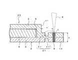
- the flat heat pipe 20 has a concave groove 21 formed in a region between the convex portion 11 and the laser welded portion 8 welded by the laser beam 9.
- a single groove 21 ′ is formed on the peripheral edge 7 of the other plate-like body 3, that is, the outer peripheral portion of the protrusion 11, which is processed in a convex shape at the center that is the laser irradiation side surface.
- one concave groove 21 ′′ is formed in the peripheral edge portion 10 of one plate-like body 4 corresponding to the position parallel to the thickness direction of the container 2 with respect to the concave groove 21 ′. Yes.
- the concave groove 21 ′ is formed so as to surround the outer periphery of the convex portion 11 formed in the central portion of the container 2, and the concave groove 21 ′′ is formed so as to surround the outer periphery of the central portion corresponding to the position of the convex portion 11.
- the groove 21 ′ and the groove 21 ′′ have the same cross-sectional shape and the same width and depth, and are formed so that the bottom surface of the groove 21 ′ and the bottom surface of the groove 21 ′′ face each other. Has been.
- the concave grooves 21 ′ and 21 ′′ prevent the melting heat of the container material generated during laser welding from being transmitted to the gap portion 5, the distortion of the gap portion 5 is further reduced.
- the width of the concave grooves 21 ′ and 21 ′′ is equal to or greater than the welding width of the laser welded portion 8 on the laser irradiation side surface of the container 2, and the convex portion 11 side end portion of the laser welded portion 8 on the laser irradiation side surface. It has a dimension corresponding to less than the shortest distance to the end (hereinafter sometimes referred to as “distance c ′”), and the depth of the concave grooves 21 ′ and 21 ′′ is equal to that of one plate-like body 4 and the other. 1/10 or more and 1/3 or less, preferably 1/6 or more, 1 / th of the thickness (the thickness a in FIG. 2, hereinafter referred to as “thickness a”). It has a dimension corresponding to 3 or less. Accordingly, the distance c ′ of the planar heat pipe 20 has a dimension larger than the welding width of the laser welded portion 8 on the laser irradiation side surface.
- the widths of the concave grooves 21 ′ and 21 ′′ are not particularly limited as long as they are in the above-described range.
- the lower limit value is the laser irradiation side from the viewpoint of reliably suppressing the heat of fusion from being transmitted to the gap portion 5. 1.5 times the welding width of the laser welded portion 8 on the surface is preferable, and 2.0 times the weld width of the laser welded portion 8 on the laser irradiation side surface is particularly preferable.
- the upper limit value of the width of the concave grooves 21 ′ and 21 ′′ prevents the temperature increase in the region from the end portion of the laser welding portion 8 on the convex portion 11 side to the end portion of the convex portion 11.
- 5 is preferably 4/5 of the dimension corresponding to the distance c ′, and particularly preferably 2/3 of the dimension corresponding to the distance c ′.
- the depths of the concave grooves 21 ′ and 21 ′′ are not particularly limited as long as they are in the above-described range. However, the transmission of the melting heat to the gap portion 5 is reliably suppressed, and the outer peripheral portion of the convex portion 11 is mechanically suppressed. From the viewpoint of ensuring strength, the dimension corresponding to the thickness a is particularly preferably from 1/5 to 1/4.
- the welding width of the laser welded portion 8 of the planar heat pipe 20 is the same as that of the planar heat pipe 1 according to the first embodiment described above.
- the lower limit value of the welding width of the laser welded portion 8 on the laser irradiation side surface is the laser welded portion 8. Is 1/10 of the dimension corresponding to the thickness a from the viewpoint of bonding strength, and preferably 1/5 of the dimension corresponding to the thickness a from the viewpoint of gas barrier properties, and is 1/4 of the dimension corresponding to the thickness a. Is particularly preferred.
- the upper limit value of the welding width of the laser welding portion 8 on the laser irradiation side surface is the welding width of the laser welding portion 8 on the laser irradiation side surface of the container 2 (the surface on the other plate-like body 3 side in FIG. 2).
- the concave grooves 21 ′ and 21 ′′ prevent the heat of fusion generated during laser welding from being transmitted to the gap 5, so that the distance c ′ is equal to the flat heat pipe 1.
- the distance c can be made shorter.
- the distance c ′ is not particularly limited, but the lower limit thereof is preferably 1 ⁇ 2 of the dimension corresponding to the thickness a from the viewpoint of preventing the distortion of the gap 5 while reducing the size of the planar heat pipe 20.
- the dimension corresponding to the thickness a is more preferable from the viewpoint of surely preventing the distortion of 5, and the dimension corresponding to the thickness a from the viewpoint of surely avoiding the influence of the distortion caused by the residual stress caused by the welding of the laser beam 9. 5 times is particularly preferable.
- the upper limit value of the distance c ′ is not particularly limited.
- the flat heat pipe 20 is reduced in size so that the flat heat pipe 20 can be installed in a narrow space. 0 times is preferable, and by shortening the welding distance by the laser beam 9, the residual stress is surely reduced, and 4.0 times the dimension corresponding to the thickness a is more preferable from the point of speeding up the processing. Double is particularly preferred.
- the position and the welding width of the laser welded portion 8 are set so that the concave grooves 21 ′ and 21 ′′ are within the above dimensions.
- planar heat pipe a case where a flexible printed wiring board on which a CPU or the like inside an electronic device such as a personal computer is mounted is cooled using the planar heat pipe of the present invention will be described as an example.
- the flat heat pipe is appropriately bent according to the state of the gap inside the electronic device and the storage state of the flexible printed wiring board, and the flexible printed wiring board is thermally connected to the heat input side of the flat heat pipe.
- a heat sink or a heat radiation fin is provided on the heat radiation side of the flat heat pipe.
- the wick structure 6 having a capillary structure is housed in the cavity 5, but instead, on the inner wall of the cavity 5, A wick structure may be formed.
- the laser beam 9 is irradiated on the surface on the other plate-like body 3 side whose center is processed into a convex shape.
- the laser beam 9 may be irradiated to the surface by the side of the one plate-shaped body 4 in which the center part is not processed into convex shape.
- the end of the convex portion 11 is the convex portion 11 of the other plate-like body 3.
- the concave groove 21 ′ and the concave groove 21 ′′ have the same cross-sectional shape and the same width and depth, but instead, different cross-sectional shapes. And / or different widths and depths.
- Example 1 A plate-like body (plate thickness: 0.1 mm) having one concave groove having a width of 0.3 mm and a depth of 0.05 mm at a position corresponding to a portion surrounding the outer periphery of the convex portion (height 0.2 mm) having a hollow portion 2) Two sheets were overlapped on the back side of each plate-like body. Next, the planar heat pipe of Example 1 was manufactured by laser welding the outer peripheral part of a ditch
- the concave groove of the plate-like body in which the convex portion on the laser irradiation side is processed and the concave groove of the plate-like body in which the convex portion is not processed on the laser irradiation side are the contact surfaces of the opposing plate-like bodies. It is formed in the same position with the border. Further, since the plate thickness of the plate-like body is 0.1 mm, the thickness of the flat heat pipe other than the convex portion (cavity portion) and the concave groove is 0.2 mm.
- Comparative Example 1 A planar heat pipe of Comparative Example 1 was produced in the same manner as in Example 1 except that the plate-like bodies having a thickness of 0.1 mm that did not have concave grooves were overlapped.
- Example 1 Flatness 0.3 mm Comparative Example 1: Flatness 0.5mm
- Example 1 having a groove on the outer peripheral portion of the convex portion (cavity portion) can obtain better flatness of the convex portion (cavity portion) than Comparative Example 1 having no concave groove.
- the distortion of the convex part (cavity part) could be prevented.
- the flat type heat pipe of the present invention is used in the field of uniformly cooling the heating element to be cooled in a planar shape because the distortion of the gap portion having the wick structure and the warpage of the whole flat type heat pipe are reduced. High value.
Landscapes
- Engineering & Computer Science (AREA)
- Physics & Mathematics (AREA)
- Thermal Sciences (AREA)
- Mechanical Engineering (AREA)
- Optics & Photonics (AREA)
- General Engineering & Computer Science (AREA)
- Life Sciences & Earth Sciences (AREA)
- Sustainable Development (AREA)
- Microelectronics & Electronic Packaging (AREA)
- Plasma & Fusion (AREA)
- Cooling Or The Like Of Semiconductors Or Solid State Devices (AREA)
- Laser Beam Processing (AREA)
- Cooling Or The Like Of Electrical Apparatus (AREA)
Abstract
ウィック構造を有する空隙部の歪みと平面型ヒートパイプ全体の反りが低減された平面型ヒートパイプを提供する。 平面型ヒートパイプ1は、対向する2枚の板状体3、4により空洞部5を有する凸部11が中央部に形成されたコンテナ2と、前記空洞部に封入された作動液とを有し、前記空洞部にウィック構造体6が備えられ、前記凸部の周縁部7が、熱をかけた溶接8にて封止され、前記凸部と前記熱をかけた溶接により溶接された溶接部との間の前記凸部の周りに、溝21(21'、21")が形成されている。
Description
本発明は、ウィック構造を有する空隙部の歪みが抑えられ、コンテナ全体の反りが低減された平面型ヒートパイプに関するものである。
電気・電子機器に搭載されている半導体素子等の電子部品は、高機能化に伴う高密度搭載等により、発熱量が増大し、近年、その冷却がより重要となっている。電子部品の冷却方法として、平面型ヒートパイプが使用されることがある。
そこで、シーム溶接にてウィック構造を有する空隙部を密封した平面型ヒートパイプが提案されている(特許文献1)。しかし、シーム溶接では、平面型ヒートパイプの溶接部の幅が広くなる傾向にあり、また、高速溶接に不向きであるという問題があった。
また、超音波溶接にてウィック構造を有する空隙部を密封した平面型ヒートパイプも提案されている(特許文献2)。しかし、超音波溶接では、溶接強度が限定されるので、ウィック構造を有する空隙部の気密性を従来よりもさらに向上させることが難しいという問題があった。
さらに、圧接にてウィック構造を有する空隙部を密封した平面型ヒートパイプも提案されている(特許文献3)。しかし、圧接は、塑性変形による接合なので、接合強度が限定され、ウィック構造を有する空隙部の気密性を従来よりもさらに向上させることが難しいという問題、ヒートパイプに歪みが生じる場合があるという問題があった。
そこで、近年、気密性に優れた空隙部を得ることができ、高速溶接にも適することから、YAGレーザーを用いた溶接にて、ウィック構造を有する空隙部を密封した平面型ヒートパイプも提案されている。しかし、YAGレーザーでの溶接では、コンテナのレーザー照射側表面におけるレーザー溶接部の幅が、コンテナのレーザー照射側とは反対側の表面のレーザー溶接部の幅と比較して、その差が大きくなってしまう。すなわち、YAGレーザーを用いた溶接では、コンテナのレーザー照射側表面の溶接部の幅が反対側表面のレーザー溶接部の幅よりも非常に広くなってしまうので、溶接部が固化する際に、上記両表面の溶接部の幅の差に起因して平面型ヒートパイプ全体に反りが生じてしまうという問題や、溶接時に生じるコンテナ材料の溶融熱が空隙部にまで伝わり、空隙部に歪みが生じてしまうという問題があった。
上記事情に鑑み、本発明は、ウィック構造を有する空隙部の歪みと平面型ヒートパイプ全体の反りが低減された平面型ヒートパイプを提供することを目的とする。
本発明の態様は、対向する2枚の板状体により空洞部を有する凸部が中央部に形成されたコンテナと、前記空洞部に封入された作動液とを有し、前記空洞部にウィック構造が備えられ、前記凸部の外周部が、熱をかけた溶接にて封止された平面型ヒートパイプであって、前記凸部と前記熱をかけた溶接により溶接された溶接部との間の前記凸部の周りに、溝が、形成されている平面型ヒートパイプである。本発明の態様は、前記溝が、前記2枚の板状体の合計の厚みの1/10以上1/3以下の深さを有する平面型ヒートパイプである。本発明の態様は、前記溝が、前記コンテナの熱をかけた側表面における前記溶接部の溶接幅以上、前記熱をかけた側表面における前記溶接部の前記凸部側端部から前記凸部の端部までの最短距離未満である幅を有する平面型ヒートパイプである。本発明の態様は、前記コンテナの熱をかけた側表面における溶接部の溶接幅が、前記2枚の板状体の合計の厚みの1/10以上、前記コンテナの熱をかけた側表面における溶接部の前記凸部側端部から前記凸部の端部までの最短距離以下である平面型ヒートパイプである。なお、上記熱をかけた溶接の溶接法は、特に限定されないが、例えば、レーザー溶接、抵抗溶接、Tig溶接、電子ビーム溶接等が挙げられ、狭い溶接しろ、加工形状の自由度及び加工タクトの向上の点から、レーザー溶接が好ましい。
本発明の態様は、前記コンテナの熱をかけた側表面における溶接部の溶接幅が、10μm以上300μm以下である平面型ヒートパイプである。
本発明の態様は、前記コンテナの熱をかけた側表面における溶接部の溶接幅:前記コンテナの熱をかけた側表面の反対側表面における溶接部の溶接幅が、1:1~1:0.8である平面型ヒートパイプである。
本発明の態様は、前記凸部の厚さが、前記2枚の板状体の合計の厚みの1/2以上である平面型ヒートパイプである。
本発明の態様は、前記コンテナの材料が、銅、銅合金、アルミニウム、アルミニウム合金、ニッケル、ニッケル合金またはステンレスである平面型ヒートパイプである。
本発明の態様は、前記2枚の板状体の合計の厚みが、0.05mm以上1.0mm以下である平面型ヒートパイプである。
本発明の態様は、前記熱をかけた溶接が、レーザー溶接である平面型ヒートパイプである。
本発明の態様は、対向する2枚の板状体により空洞部を有する凸部が中央部に形成されたコンテナと、前記空洞部に封入された作動液とを有し、前記空洞部にウィック構造が備えられ、前記凸部の外周部がレーザー溶接にて封止された平面型ヒートパイプであって、前記コンテナのレーザー照射側表面におけるレーザー溶接部の前記凸部側端部から前記凸部の端部までの最短距離が、前記2枚の板状体の合計の厚み以上であり、前記レーザー照射側表面におけるレーザー溶接部の溶接幅が、前記2枚の板状体の合計の厚みの1/10以上、前記レーザー照射側表面におけるレーザー溶接部の前記凸部側端部から前記凸部の端部までの最短距離以下である平面型ヒートパイプである。
本発明の態様によれば、溝が、凸部の周りに形成されることにより、溶接時に生じるコンテナ材料の溶融熱が空洞部にまで伝わるのを前記溝が抑制するので、空洞部の歪みが低減される。また、溝が、凸部の周りに形成され、熱をかけた側表面における溶接部の溶接幅が、2枚の板状体の合計の厚みの1/10以上、熱をかけた側表面における溶接部の凸部側端部から凸部の端部までの最短距離以下であることにより、溶接時に生じるコンテナ材料の溶融熱が空洞部にまで伝わるのを前記溝が抑制するので、空洞部の歪みが低減され、さらに、コンテナの熱をかけた側表面の溶接部の溶接幅と反対側表面の溶接部の溶接幅との差が小さいので、溶接部の固化にあたり、平面型ヒートパイプ全体の反りが低減される。すなわち、本発明の溝を有する平面型ヒートパイプは、優れた溶接部の接合強度を有しつつ、空洞部の歪みと全体の反りが低減した平面型ヒートパイプである。
本発明の態様によれば、コンテナの熱をかけた側表面における溶接部の溶接幅が、10μm以上300μm以下であることにより、コンテナの熱をかけた側表面の溶接部の溶接幅と反対側表面の溶接部の溶接幅との差がより確実に小さくなる。
本発明の態様によれば、コンテナの熱をかけた側表面における溶接部の溶接幅:コンテナの熱をかけた側表面の反対側表面における溶接部の溶接幅が、1:1~1:0.8であることにより、平面型ヒートパイプ全体の反りがより確実に低減される。
本発明の態様によれば、コンテナのレーザー照射側表面におけるレーザー溶接部の凸部側端部から凸部の端部までの最短距離が、2枚の板状体の合計の厚み以上であり、レーザー照射側表面におけるレーザー溶接部の溶接幅が、2枚の板状体の合計の厚みの1/10以上、レーザー照射側表面におけるレーザー溶接部の凸部側端部から凸部の端部までの最短距離以下であることにより、溶接時に生じるコンテナ材料の溶融熱が空洞部にまで伝わって空洞部に歪みが生じてしまうのが防止され、さらに、コンテナのレーザー照射側表面のレーザー溶接部の溶接幅と反対側表面のレーザー溶接部の溶接幅との差が小さいので、溶接部の固化にあたり、平面型ヒートパイプ全体の反りが低減される。すなわち、本発明の平面型ヒートパイプは、優れたレーザー溶接部の接合強度を有しつつ、空洞部の歪みと全体の反りが低減した平面型ヒートパイプである。
以下に、本発明の第1実施形態例に係る平面型ヒートパイプについて、図面を用いながら説明する。図1に示すように、第1実施形態例に係る平面型ヒートパイプ1は、対向する2枚の板状体、すなわち、一方の板状体4と他方の板状体3とを重ねることにより空洞部5を有する凸部11が中央部に形成された平面視矩形状のコンテナ2と、空洞部5に封入された作動液(図示せず)とを有している。空洞部5内には、毛細管構造を有するウィック構造体6が収納されている。
一方の板状体4は平板状である。他方の板状体3も平板状であるが、中央部が凸状に塑性変形されている。この他方の板状体3の、外側に向かって突出し、凸状に塑性変形された部位が、コンテナ2の凸部11となる。図1では、凸部11は、凸部11の外周部の表面に対して垂直に突出している。凸部11の内部が、空洞部5となっている。平面型ヒートパイプ1は、凸部11の外周部がレーザー溶接されることで空洞部5が封止され、空洞部5に気密性が付与される。
平面型ヒートパイプ1では、中央部が凸状に加工された他方の板状体3の周縁部7、すなわち、凸部11が形成されていないコンテナ2の周縁部が、レーザー光線9により溶接されてレーザー溶接部8が形成されている。レーザー溶接部8により、一方の板状体4と他方の板状体3とが接合されている。レーザー照射側表面のレーザー溶接部8の凸部11側端部から凸部11の端部、すなわち、凸部11の外周部の表面と凸部11との境界部までの最短距離(図1の距離c、以下、「距離c」ということがある。)が、一方の板状体4と他方の板状体3とを重ね合わせた厚み(図1の厚さa、以下、「厚さa」ということがある。)以上の寸法となる位置に、レーザー溶接部8が設けられている。これにより、溶接時に生じるコンテナ材料の溶融熱が空隙部5にまで伝わるのを防止できるので、平面型ヒートパイプ1の空隙部5の歪みが低減される。
距離cの下限値は、厚さaに相当する寸法であり、前記溶融熱が空隙部5にまで伝わるのを確実に防止する点から、厚さaに相当する寸法の1.5倍が好ましく、レーザー光線9の溶接によって生じる残留応力による歪みの影響を確実に避ける点から厚さaに相当する寸法の2.0倍が特に好ましい。一方で、距離cの上限値は、特に限定されないが、平面型ヒートパイプ1を小型化して狭い空間にも平面型ヒートパイプ1を設置可能とする点から、厚さaに相当する寸法の5.0倍が好ましく、レーザー光線9による溶接距離を短縮することで、残留応力を確実に低減し、加工を高速化する点から厚さaに相当する寸法の4.0倍がより好ましく、3.0倍が特に好ましい。
なお、レーザー溶接部8とレーザー溶接されていない部位との境界の判断は、肉眼にて、レーザー溶接部8表面を観察するか、またはレーザー溶接部8の断面を観察することにより行うことができる。また、本明細書中、「溶接幅」とは、熱をかけた溶接により生じる線状の軟化変形領域の幅であって、マイクロスコープにより溶接領域を均等に10箇所測定したときの平均値を意味する。
レーザー照射側表面(図1では、中央部が凸状に加工された他方の板状体3側の表面)におけるレーザー溶接部8の溶接幅の下限値は、レーザー溶接部8の接合強度の点から厚さaに相当する寸法の1/10であり、ガスバリア性の点から厚さaに相当する寸法の1/5が好ましく、厚さaに相当する寸法の1/4が特に好ましい。一方で、レーザー照射側表面におけるレーザー溶接部8の溶接幅の上限値は、コンテナ2のレーザー照射側表面(図1では、他方の板状体3側の表面)のレーザー溶接部8の溶接幅と反対側表面(図1では、一方の板状体4側の表面)のレーザー溶接部8の溶接幅との差を小さくすることで、全体としての反りが低減された平面型ヒートパイプ1とする点から、レーザー溶接部8の凸部11側端部から凸部11の端部までの最短距離(すなわち、距離c)に相当する寸法であり、レーザー溶接部8近傍の僅かな反りも抑制する点から、距離cに相当する寸法の3/5が好ましく、残留応力を確実に低減する点から、距離cに相当する寸法の1/2がより好ましく、平面型ヒートパイプ1の小型化の点から、距離cに相当する寸法の1/4が特に好ましい。従って、レーザー溶接部8の位置と溶接幅が上記範囲となるように、厚さaに相当する寸法と距離cに相当する寸法を設定する。
コンテナ2のレーザー照射側表面におけるレーザー溶接部8の溶接幅は、上記範囲であれば特に限定されず、具体例として、厚さaが100μmのコンテナ2の場合には、その下限値は、10μmであり、20μmが好ましく、25μmが特に好ましい。一方で、その上限値は、例えば、500μmであり、300μmが好ましく、250μmがより好ましく、125μmが特に好ましい。
コンテナ2のレーザー照射側表面におけるレーザー溶接部8の溶接幅:コンテナ2のレーザー照射側表面の反対側表面におけるレーザー溶接部8の溶接幅は、全体としての反りが低減された平面型ヒートパイプ1とする点から、1:1~1:0.80が好ましく、レーザー溶接部8近傍の僅かな反りも抑制する点から、1:1~1:0.85がより好ましく、コンテナ2のレーザー照射側表面とその反対側表面とで生じる残留応力の差を確実に抑制する点から、1:1~1:0.90が特に好ましい。
上記レーザー溶接部8の溶接幅にて溶接できるレーザーとして、コンテナ2のレーザー照射側表面における集光径が小さい、例えば、前記集光径が20~200μmであるレーザーを挙げることができる。該レーザーとしては、例えば、ファイバーレーザーを挙げることができる。
凸部11の厚さ(図1の厚さb)は、適宜選択可能であり、例えば、平面型ヒートパイプ1の曲げ性と冷却効率とのバランスの点から、厚さaに相当する寸法の1/2以上、厚さaに相当する寸法以下が好ましい。また、厚さaは、適宜選択可能であり、例えば、薄型化の点から0.05mm以上1.0mm以下が好ましく、耐圧性と加工性の点から0.1mm以上0.8mm以下が特に好ましい。
コンテナ2の材料としては、例えば、銅、銅合金、アルミニウム、アルミニウム合金、ニッケル、ニッケル合金、ステンレス等を挙げることができる。また、空洞部5に封入する作動液としては、コンテナ2の材料との適合性に応じて、適宜選択可能であり、例えば、水、代替フロン、フロリーナ、シクロペンタン等を挙げることができる。
毛細管構造を有するウィック構造体6としては、例えば、メッシュ、ワイヤ等を有する薄板を挙げることができる。
次に、本発明の第2実施形態例に係る平面型ヒートパイプについて、図面を用いながら説明する。本発明の第1実施形態例に係る平面型ヒートパイプ1と同じ構成要素については同じ符号を用いて説明する。
図2に示すように、第2実施形態例に係る平面型ヒートパイプ20には、凸部11とレーザー光線9により溶接されたレーザー溶接部8との間の領域に、凹溝21が形成されている。図2では、レーザー照射側表面である中央部が凸状に加工された他方の板状体3の周縁部7、すなわち、凸部11の外周部に1本の凹溝21’が形成されている。さらに、凹溝21’に対して、コンテナ2の厚さ方向に対して平行方向の位置に対応する一方の板状体4の周縁部10に、1本の凹溝21’’が形成されている。凹溝21’は、コンテナ2中央部に形成された凸部11の外周を囲むように形成され、凹溝21’’は、凸部11の位置に相当する中央部の外周を囲むように形成されている。また、凹溝21’と凹溝21’’は、同一の断面形状及び同一の幅と深さであり、凹溝21’の底面部と凹溝21’’の底面部が対向するように形成されている。
凹溝21’、21’’が、レーザー溶接時に生じるコンテナ材料の溶融熱が空隙部5にまで伝わるのを抑制するので、空隙部5の歪みがより低減される。
凹溝21’、21’’の幅は、コンテナ2のレーザー照射側表面におけるレーザー溶接部8の溶接幅以上、レーザー照射側表面におけるレーザー溶接部8の凸部11側端部から凸部11の端部までの最短距離(以下、「距離c’」ということがある。)未満に相当する寸法を有し、凹溝21’、21’’の深さは、一方の板状体4と他方の板状体3とを重ね合わせた厚み(図2の厚さa、以下、「厚さa」ということがある。)の1/10以上1/3以下、好ましくは1/6以上1/3以下に相当する寸法を有する。従って、平面型ヒートパイプ20の距離c’は、レーザー照射側表面におけるレーザー溶接部8の溶接幅よりも大きい寸法を有していることとなる。
凹溝21’、21’’の幅は、上記した範囲であれば特に限定されないが、その下限値は、空隙部5にまで前記溶融熱が伝わるのを確実に抑制する点から、レーザー照射側表面におけるレーザー溶接部8の溶接幅の1.5倍が好ましく、レーザー照射側表面におけるレーザー溶接部8の溶接幅の2.0倍が特に好ましい。一方、凹溝21’、21’’の幅の上限値は、レーザー溶接部8の凸部11側端部から凸部11の端部までの領域の温度上昇を防止して、ひいては、空洞部5の歪みを防止する点から、距離c’に相当する寸法の4/5が好ましく、距離c’に相当する寸法の2/3が特に好ましい。
凹溝21’、21’’の深さは、上記した範囲であれば特に限定されないが、空隙部5にまで前記溶融熱が伝わるのを確実に抑制しつつ、凸部11外周部の機械的強度を確保する点から、厚さaに相当する寸法の1/5以上1/4以下が特に好ましい。
平面型ヒートパイプ20のレーザー溶接部8の溶接幅は、上記した第1実施形態例に係る平面型ヒートパイプ1と同様にする。具体的には、レーザー照射側表面(図2では、中央部が凸状に加工された他方の板状体3側の表面)におけるレーザー溶接部8の溶接幅の下限値は、レーザー溶接部8の接合強度の点から厚さaに相当する寸法の1/10であり、ガスバリア性の点から厚さaに相当する寸法の1/5が好ましく、厚さaに相当する寸法の1/4が特に好ましい。一方で、レーザー照射側表面におけるレーザー溶接部8の溶接幅の上限値は、コンテナ2のレーザー照射側表面(図2では、他方の板状体3側の表面)のレーザー溶接部8の溶接幅と反対側表面(図2では、一方の板状体4側の表面)のレーザー溶接部8の溶接幅との差を小さくすることで、全体としての反りが低減された平面型ヒートパイプ20とする点から、距離c’に相当する寸法であり、レーザー溶接部8近傍の僅かな反りも抑制する点から、距離c’に相当する寸法の3/5が好ましく、残留応力を確実に低減する点から、距離c’に相当する寸法の1/2がより好ましく、平面型ヒートパイプ20の小型化の点から、距離c’に相当する寸法の1/4が特に好ましい。
平面型ヒートパイプ20では、上記の通り、凹溝21’、21’’が、レーザー溶接時に生じる溶融熱が空隙部5にまで伝わるのを抑制するので、距離c’は、平面型ヒートパイプ1の距離cよりも短くすることができる。
距離c’は特に限定されないが、その下限値は、平面型ヒートパイプ20を小型化しつつ空隙部5の歪みを防止する点から、厚さaに相当する寸法の1/2が好ましく、空隙部5の歪みの確実な防止の点から、厚さaに相当する寸法がより好ましく、レーザー光線9の溶接によって生じる残留応力による歪みの影響を確実に避ける点から厚さaに相当する寸法の1.5倍が特に好ましい。一方で、距離c’の上限値は、特に限定されないが、平面型ヒートパイプ20を小型化して狭い空間にも平面型ヒートパイプ20を設置可能とする点から、厚さaする寸法の5.0倍が好ましく、レーザー光線9による溶接距離を短縮することで、残留応力を確実に低減し、加工を高速化する点から厚さaに相当する寸法の4.0倍がより好ましく、3.0倍が特に好ましい。
第2実施形態例に係る平面型ヒートパイプ20では、凹溝21’、21’’が、上記寸法の範囲となるように、レーザー溶接部8の位置と溶接幅を設定する。
次に、本発明の実施形態例に係る平面型ヒートパイプの使用方法例について説明する。ここでは、パソコン等の電子機器内部のCPU等が実装されているフレキシブルプリント配線板を、本発明の平面型ヒートパイプを用いて冷却する場合を例にとって説明する。電子機器内部の空隙の状況とフレキシブルプリント配線板の収納状況に応じて、適宜、平面型ヒートパイプを曲げて、フレキシブルプリント配線板を平面型ヒートパイプの入熱側と熱的に接続させる。平面型ヒートパイプの放熱側には、必要に応じて、ヒートシンクや放熱用のフィンを設ける。これにより、電子機器内部の狭い空間に収容されたフレキシブルプリント配線板を面状に冷却することができる。
次に、本発明のその他の実施形態例について説明する。上記各実施形態例に係る平面型ヒートパイプ1、20では、空洞部5内には、毛細管構造を有するウィック構造体6が収納されていたが、これに代えて、空洞部5の内壁に、ウィック構造を形成してもよい。
また、上記各実施形態例に係る平面型ヒートパイプ1、20では、中央部が凸状に加工された他方の板状体3側の表面に、レーザー光線9が照射されていたが、これに代えて、中央部が凸状に加工されていない一方の板状体4側の表面に、レーザー光線9が照射されてもよい。一方の板状体4側の表面に、レーザー光線9が照射される場合には、レーザー溶接部8の位置を設定するにあたり、凸部11の端部は、他方の板状体3の凸部11の外周部表面と凸部11との境界部をコンテナ2の厚さ方向に対して平行方向に移動させた、一方の板状体4表面上の部位となる。すなわち、一方の板状体4における凸部11の端部は、他方の板状体3の凸部11の外周部表面と凸部11との境界部の位置に対応した、一方の板状体4表面上の部位となる。
第2実施形態例に係る平面型ヒートパイプ20では、凹溝21’と凹溝21’’は、同一の断面形状及び同一の幅と深さであったが、これに代えて、異なる断面形状及び/または異なる幅と深さとしてもよい。
次に、本発明の実施例を説明するが、本発明はその趣旨を超えない限り、これらの例に限定されるものではない。
実施例1
空洞部を有する凸部(高さ0.2mm)の外周を囲む部位に相当する位置に、幅0.3mm、深さ0.05mmの凹溝を1本有する板状体(板厚0.1mm)2枚を、各板状体の裏面側にて重ね合わせた。次に、凹溝の外周部をレーザー溶接(レーザー光線の幅0.02mm)することにより、実施例1の平面型ヒートパイプを製造した。なお、レーザー照射側である凸部が加工された板状体の凹溝と、レーザー照射側ではなく凸部が加工されていない板状体の凹溝とは、対向する板状体の接触面を境にして、同じ位置に形成されている。また、板状体の板厚は0.1mmなので、平面型ヒートパイプの、凸部(空洞部)及び凹溝以外の厚さは、0.2mmである。
空洞部を有する凸部(高さ0.2mm)の外周を囲む部位に相当する位置に、幅0.3mm、深さ0.05mmの凹溝を1本有する板状体(板厚0.1mm)2枚を、各板状体の裏面側にて重ね合わせた。次に、凹溝の外周部をレーザー溶接(レーザー光線の幅0.02mm)することにより、実施例1の平面型ヒートパイプを製造した。なお、レーザー照射側である凸部が加工された板状体の凹溝と、レーザー照射側ではなく凸部が加工されていない板状体の凹溝とは、対向する板状体の接触面を境にして、同じ位置に形成されている。また、板状体の板厚は0.1mmなので、平面型ヒートパイプの、凸部(空洞部)及び凹溝以外の厚さは、0.2mmである。
比較例1
凹溝を有さない板厚0.1mmの板状体を重ね合わせた以外は、実施例1と同様にして、比較例1の平面型ヒートパイプを製造した。
凹溝を有さない板厚0.1mmの板状体を重ね合わせた以外は、実施例1と同様にして、比較例1の平面型ヒートパイプを製造した。
平面度評価
実施例1の平面型ヒートパイプ及び比較例1の平面型ヒートパイプについて、それぞれ、レーザー変位計(高速・高精度CCDレーザー変位計 keyence LK-G30、3次元アーム:IAI TABLE TOP TT)を用いて、凸部(空洞部)の高さを測定した。測定点は、長手方向に一方の端部から他方の端部まで等間隔に7点、短手方向に一方の端部から他方の端部まで等間隔に3点の計21点とした。この21の測定点の座標から最小二乗法により、基準となる仮想平面を算出し、「測定点21点のうちの該仮想平面からの最大高さ-測定点21点のうちの該仮想平面からの最小高さ」にて、凸部(空洞部)の平面度を算出した。
実施例1の平面型ヒートパイプ及び比較例1の平面型ヒートパイプについて、それぞれ、レーザー変位計(高速・高精度CCDレーザー変位計 keyence LK-G30、3次元アーム:IAI TABLE TOP TT)を用いて、凸部(空洞部)の高さを測定した。測定点は、長手方向に一方の端部から他方の端部まで等間隔に7点、短手方向に一方の端部から他方の端部まで等間隔に3点の計21点とした。この21の測定点の座標から最小二乗法により、基準となる仮想平面を算出し、「測定点21点のうちの該仮想平面からの最大高さ-測定点21点のうちの該仮想平面からの最小高さ」にて、凸部(空洞部)の平面度を算出した。
平面度の算出結果を以下に示す。
実施例1:平面度0.3mm
比較例1:平面度0.5mm
実施例1:平面度0.3mm
比較例1:平面度0.5mm
上記から、凸部(空洞部)の外周部に凹溝を有する実施例1は、凹溝を有さない比較例1と比較して、良好な凸部(空洞部)の平面度が得られ、凸部(空洞部)の歪みを防止できた。
本発明の平面型ヒートパイプは、ウィック構造を有する空隙部の歪みと平面型ヒートパイプ全体の反りが低減されているので、特に、冷却対象の発熱体を面状に均一に冷却する分野で利用価値が高い。
1、20 平面型ヒートパイプ
2 コンテナ
3 他方の板状体
4 一方の板状体
5 空洞部
8 レーザー溶接部
21 凹溝
2 コンテナ
3 他方の板状体
4 一方の板状体
5 空洞部
8 レーザー溶接部
21 凹溝
Claims (10)
- 対向する2枚の板状体により空洞部を有する凸部が中央部に形成されたコンテナと、前記空洞部に封入された作動液とを有し、前記空洞部にウィック構造が備えられ、前記凸部の外周部が、熱をかけた溶接にて封止された平面型ヒートパイプであって、
前記凸部と前記熱をかけた溶接により溶接された溶接部との間の前記凸部の周りに、溝が、形成されている平面型ヒートパイプ。 - 前記溝が、前記2枚の板状体の合計の厚みの1/10以上1/3以下の深さを有する請求項1に記載の平面型ヒートパイプ。
- 前記溝が、前記コンテナの熱をかけた側表面における前記溶接部の溶接幅以上、前記熱をかけた側表面における前記溶接部の前記凸部側端部から前記凸部の端部までの最短距離未満である幅を有する請求項1に記載の平面型ヒートパイプ。
- 前記コンテナの熱をかけた側表面における溶接部の溶接幅が、前記2枚の板状体の合計の厚みの1/10以上、前記コンテナの熱をかけた側表面における溶接部の前記凸部側端部から前記凸部の端部までの最短距離以下である請求項1に記載の平面型ヒートパイプ。
- 前記コンテナの熱をかけた側表面における溶接部の溶接幅が、10μm以上300μm以下である請求項1に記載の平面型ヒートパイプ。
- 前記コンテナの熱をかけた側表面における溶接部の溶接幅:前記コンテナの熱をかけた側表面の反対側表面における溶接部の溶接幅が、1:1~1:0.8である請求項1に記載の平面型ヒートパイプ。
- 前記凸部の厚さが、前記2枚の板状体の合計の厚みの1/2以上である請求項1に記載の平面型ヒートパイプ。
- 前記コンテナの材料が、銅、銅合金、アルミニウム、アルミニウム合金、ニッケル、ニッケル合金またはステンレスである請求項1に記載の平面型ヒートパイプ。
- 前記2枚の板状体の合計の厚みが、0.05mm以上1.0mm以下である請求項1に記載の平面型ヒートパイプ。
- 前記熱をかけた溶接が、レーザー溶接である請求項1に記載の平面型ヒートパイプ。
Priority Applications (2)
| Application Number | Priority Date | Filing Date | Title |
|---|---|---|---|
| CN201590000847.8U CN206546117U (zh) | 2014-08-01 | 2015-07-21 | 平面型热管 |
| US15/418,811 US20170138673A1 (en) | 2014-08-01 | 2017-01-30 | Planar Heat Pipe |
Applications Claiming Priority (2)
| Application Number | Priority Date | Filing Date | Title |
|---|---|---|---|
| JP2014157713A JP5740036B1 (ja) | 2014-08-01 | 2014-08-01 | 平面型ヒートパイプ |
| JP2014-157713 | 2014-08-01 |
Related Child Applications (1)
| Application Number | Title | Priority Date | Filing Date |
|---|---|---|---|
| US15/418,811 Continuation US20170138673A1 (en) | 2014-08-01 | 2017-01-30 | Planar Heat Pipe |
Publications (1)
| Publication Number | Publication Date |
|---|---|
| WO2016017471A1 true WO2016017471A1 (ja) | 2016-02-04 |
Family
ID=53534140
Family Applications (1)
| Application Number | Title | Priority Date | Filing Date |
|---|---|---|---|
| PCT/JP2015/070677 Ceased WO2016017471A1 (ja) | 2014-08-01 | 2015-07-21 | 平面型ヒートパイプ |
Country Status (5)
| Country | Link |
|---|---|
| US (1) | US20170138673A1 (ja) |
| JP (1) | JP5740036B1 (ja) |
| CN (1) | CN206546117U (ja) |
| TW (1) | TWI583910B (ja) |
| WO (1) | WO2016017471A1 (ja) |
Cited By (5)
| Publication number | Priority date | Publication date | Assignee | Title |
|---|---|---|---|---|
| WO2018198350A1 (ja) * | 2017-04-28 | 2018-11-01 | 株式会社村田製作所 | ベーパーチャンバー |
| WO2018199215A1 (ja) * | 2017-04-28 | 2018-11-01 | 株式会社村田製作所 | ベーパーチャンバー |
| WO2019009323A1 (ja) * | 2017-07-04 | 2019-01-10 | 豊田鉄工株式会社 | 車両ボデー構造部材 |
| WO2020026907A1 (ja) * | 2018-07-31 | 2020-02-06 | 株式会社村田製作所 | ベーパーチャンバー |
| WO2020100364A1 (ja) * | 2018-11-16 | 2020-05-22 | 株式会社村田製作所 | ベーパーチャンバー及びベーパーチャンバーの製造方法 |
Families Citing this family (17)
| Publication number | Priority date | Publication date | Assignee | Title |
|---|---|---|---|---|
| CN110167312B (zh) * | 2018-02-12 | 2020-12-25 | 台达电子工业股份有限公司 | 均温板支撑结构及其制法 |
| JP6859993B2 (ja) * | 2018-09-28 | 2021-04-14 | 日本製鉄株式会社 | 電池外装材、電池、およびそれらの製造方法 |
| WO2020100378A1 (ja) * | 2018-11-16 | 2020-05-22 | 株式会社村田製作所 | ベーパーチャンバー |
| CN111954789B (zh) * | 2019-03-15 | 2021-11-19 | 株式会社村田制作所 | 均热板 |
| CN215864819U (zh) * | 2019-11-06 | 2022-02-18 | 古河电气工业株式会社 | 均热板 |
| JP6877513B2 (ja) * | 2019-11-06 | 2021-05-26 | 古河電気工業株式会社 | ベーパーチャンバ |
| JP7132958B2 (ja) * | 2020-01-31 | 2022-09-07 | 古河電気工業株式会社 | ベーパーチャンバ |
| JP6998979B2 (ja) | 2020-01-31 | 2022-01-18 | 古河電気工業株式会社 | ベーパーチャンバ |
| JP7536530B2 (ja) * | 2020-06-30 | 2024-08-20 | 古河電気工業株式会社 | 熱輸送デバイスおよび熱輸送デバイスの製造方法 |
| KR102890022B1 (ko) * | 2020-11-23 | 2025-11-25 | 삼성전자주식회사 | 열 확산 구조 및 이를 포함하는 전자 장치 |
| TWI733623B (zh) * | 2020-11-25 | 2021-07-11 | 建準電機工業股份有限公司 | 具有易銲結構的散熱裝置 |
| JP7609652B2 (ja) * | 2021-02-19 | 2025-01-07 | 株式会社神戸製鋼所 | 銅合金板の接合方法及び銅合金板の接合体 |
| CN113916031A (zh) * | 2021-10-15 | 2022-01-11 | 东莞领益精密制造科技有限公司 | 均热板及其制造方法 |
| EP4439654A4 (en) * | 2021-11-24 | 2026-01-14 | Kmw Inc | HEATING ELEMENT COOLING STRUCTURE AND ITS MANUFACTURING PROCESS |
| CN114515939B (zh) * | 2022-01-25 | 2025-06-24 | 中国船舶集团有限公司第七二四研究所 | 一种真空扩散焊微通道冷板装夹修正方法 |
| CN115283773A (zh) * | 2022-07-21 | 2022-11-04 | 瑞泰精密科技(沭阳)有限公司 | 一种均温板腔体密封工艺及均温板 |
| JP2025524063A (ja) * | 2022-07-29 | 2025-07-25 | ケーエムダブリュ・インコーポレーテッド | ヒートシンク構造体 |
Citations (8)
| Publication number | Priority date | Publication date | Assignee | Title |
|---|---|---|---|---|
| JP2004138347A (ja) * | 2002-10-18 | 2004-05-13 | Sasanuma Seisakusho:Kk | 受熱ジャケット |
| JP2007113864A (ja) * | 2005-10-21 | 2007-05-10 | Sony Corp | 熱輸送装置及び電子機器 |
| JP2007260743A (ja) * | 2006-03-29 | 2007-10-11 | Tokyu Car Corp | レーザ溶接方法 |
| JP2010019495A (ja) * | 2008-07-10 | 2010-01-28 | Sony Corp | 熱輸送デバイス、電子機器、封入装置、封入方法及び熱輸送デバイスの製造方法 |
| JP2010158717A (ja) * | 2008-12-09 | 2010-07-22 | Nippon Steel Corp | 高強度薄鋼板のレーザ重ね溶接継手及びその製造方法 |
| JP2010243077A (ja) * | 2009-04-07 | 2010-10-28 | Sony Corp | 熱輸送デバイスの製造方法、熱輸送デバイス、電子機器及びカシメピン |
| JP2012115876A (ja) * | 2010-12-01 | 2012-06-21 | Toyota Motor Corp | レーザ溶接方法 |
| JP2012240083A (ja) * | 2011-05-19 | 2012-12-10 | Nippon Steel Corp | 耐遅れ破壊特性に優れた鋼板溶接部の製造方法およびその溶接部を有する鋼構造物 |
Family Cites Families (7)
| Publication number | Priority date | Publication date | Assignee | Title |
|---|---|---|---|---|
| US6871701B2 (en) * | 2001-04-09 | 2005-03-29 | The Furukawa Electric Co., Ltd. | Plate-type heat pipe and method for manufacturing the same |
| DE60312962T2 (de) * | 2003-05-13 | 2007-12-13 | Lasag Ag | Laser Punktschweissverfahren und -vorrichtung zum wirksamen Prüfen der Schweissqualität |
| KR20050032888A (ko) * | 2003-10-02 | 2005-04-08 | 엘에스전선 주식회사 | 판형 열전달 장치 |
| US20220228811A9 (en) * | 2008-07-21 | 2022-07-21 | The Regents Of The University Of California | Titanium-based thermal ground plane |
| WO2010036442A1 (en) * | 2008-07-21 | 2010-04-01 | The Regents Of The University Of California | Titanium-based thermal ground plane |
| TW201144740A (en) * | 2010-06-14 | 2011-12-16 | Chaun Choung Technology Corp | Capillary structure of thermal plate |
| TW201403017A (zh) * | 2012-07-13 | 2014-01-16 | Forcecon Technology Co Ltd | 具有無管式密封結構之薄形化熱傳導裝置及其成型方法 |
-
2014
- 2014-08-01 JP JP2014157713A patent/JP5740036B1/ja active Active
-
2015
- 2015-07-21 CN CN201590000847.8U patent/CN206546117U/zh not_active Expired - Lifetime
- 2015-07-21 WO PCT/JP2015/070677 patent/WO2016017471A1/ja not_active Ceased
- 2015-07-24 TW TW104124011A patent/TWI583910B/zh active
-
2017
- 2017-01-30 US US15/418,811 patent/US20170138673A1/en not_active Abandoned
Patent Citations (8)
| Publication number | Priority date | Publication date | Assignee | Title |
|---|---|---|---|---|
| JP2004138347A (ja) * | 2002-10-18 | 2004-05-13 | Sasanuma Seisakusho:Kk | 受熱ジャケット |
| JP2007113864A (ja) * | 2005-10-21 | 2007-05-10 | Sony Corp | 熱輸送装置及び電子機器 |
| JP2007260743A (ja) * | 2006-03-29 | 2007-10-11 | Tokyu Car Corp | レーザ溶接方法 |
| JP2010019495A (ja) * | 2008-07-10 | 2010-01-28 | Sony Corp | 熱輸送デバイス、電子機器、封入装置、封入方法及び熱輸送デバイスの製造方法 |
| JP2010158717A (ja) * | 2008-12-09 | 2010-07-22 | Nippon Steel Corp | 高強度薄鋼板のレーザ重ね溶接継手及びその製造方法 |
| JP2010243077A (ja) * | 2009-04-07 | 2010-10-28 | Sony Corp | 熱輸送デバイスの製造方法、熱輸送デバイス、電子機器及びカシメピン |
| JP2012115876A (ja) * | 2010-12-01 | 2012-06-21 | Toyota Motor Corp | レーザ溶接方法 |
| JP2012240083A (ja) * | 2011-05-19 | 2012-12-10 | Nippon Steel Corp | 耐遅れ破壊特性に優れた鋼板溶接部の製造方法およびその溶接部を有する鋼構造物 |
Cited By (9)
| Publication number | Priority date | Publication date | Assignee | Title |
|---|---|---|---|---|
| WO2018198350A1 (ja) * | 2017-04-28 | 2018-11-01 | 株式会社村田製作所 | ベーパーチャンバー |
| WO2018199215A1 (ja) * | 2017-04-28 | 2018-11-01 | 株式会社村田製作所 | ベーパーチャンバー |
| US11150030B2 (en) | 2017-04-28 | 2021-10-19 | Murata Manufacturing Co., Ltd. | Vapor chamber |
| WO2019009323A1 (ja) * | 2017-07-04 | 2019-01-10 | 豊田鉄工株式会社 | 車両ボデー構造部材 |
| WO2020026907A1 (ja) * | 2018-07-31 | 2020-02-06 | 株式会社村田製作所 | ベーパーチャンバー |
| JP6702524B1 (ja) * | 2018-07-31 | 2020-06-03 | 株式会社村田製作所 | ベーパーチャンバー |
| US11421943B2 (en) | 2018-07-31 | 2022-08-23 | Murata Manufacturing Co., Ltd. | Vapor chamber |
| WO2020100364A1 (ja) * | 2018-11-16 | 2020-05-22 | 株式会社村田製作所 | ベーパーチャンバー及びベーパーチャンバーの製造方法 |
| US11566851B2 (en) | 2018-11-16 | 2023-01-31 | Murata Manufacturing Co., Ltd. | Vapor chamber and method of manufacturing vapor chamber |
Also Published As
| Publication number | Publication date |
|---|---|
| JP5740036B1 (ja) | 2015-06-24 |
| TWI583910B (zh) | 2017-05-21 |
| CN206546117U (zh) | 2017-10-10 |
| US20170138673A1 (en) | 2017-05-18 |
| JP2016035348A (ja) | 2016-03-17 |
| TW201610385A (zh) | 2016-03-16 |
Similar Documents
| Publication | Publication Date | Title |
|---|---|---|
| JP5740036B1 (ja) | 平面型ヒートパイプ | |
| JP5788069B1 (ja) | 平面型ヒートパイプ | |
| CN103228388B (zh) | 钎焊方法以及钎焊构造 | |
| US20190271511A1 (en) | Vapor chamber | |
| TWI815076B (zh) | 蒸氣室 | |
| CN211903865U (zh) | 均热板 | |
| JP6773253B1 (ja) | ベーパーチャンバー | |
| JP6803015B1 (ja) | ベーパーチャンバ、電子機器、ベーパーチャンバ用金属シートおよびベーパーチャンバの製造方法 | |
| CN112771344B (zh) | 均热板 | |
| WO2018198354A1 (ja) | ベーパーチャンバー | |
| CN103339723A (zh) | 半导体模块用散热板的制造方法、该散热板以及使用该散热板的半导体模块 | |
| JP5962820B2 (ja) | 液冷ジャケットの製造方法 | |
| JP6395530B2 (ja) | 半導体装置 | |
| US9437520B2 (en) | Semiconductor device including a semiconductor element and a fixed member to which the semiconductor element is fixed | |
| JP5838910B2 (ja) | 冷却器及び冷却器の製造方法 | |
| CN110756990A (zh) | 焊接方法、焊接物的制造方法、以及焊接物 | |
| JP5801118B2 (ja) | 真空容器の製造方法 | |
| JP6422726B2 (ja) | 回路基板付きヒートシンク及びその製造方法 | |
| JP2015195592A (ja) | 真空容器の製造方法 | |
| JP2016152344A (ja) | 半導体装置 | |
| JP5971171B2 (ja) | 絶縁基板及びその製造方法、半導体装置 | |
| KR101099052B1 (ko) | 냉각 판 및 그 제조방법 | |
| JP2019140198A (ja) | 回路基板付きヒートシンク | |
| JP2016103526A (ja) | 半導体装置 | |
| JP2016105508A (ja) | 半導体装置 |
Legal Events
| Date | Code | Title | Description |
|---|---|---|---|
| 121 | Ep: the epo has been informed by wipo that ep was designated in this application |
Ref document number: 15828076 Country of ref document: EP Kind code of ref document: A1 |
|
| NENP | Non-entry into the national phase |
Ref country code: DE |
|
| 122 | Ep: pct application non-entry in european phase |
Ref document number: 15828076 Country of ref document: EP Kind code of ref document: A1 |