WO2016013536A1 - 基板収納容器 - Google Patents
基板収納容器 Download PDFInfo
- Publication number
- WO2016013536A1 WO2016013536A1 PCT/JP2015/070655 JP2015070655W WO2016013536A1 WO 2016013536 A1 WO2016013536 A1 WO 2016013536A1 JP 2015070655 W JP2015070655 W JP 2015070655W WO 2016013536 A1 WO2016013536 A1 WO 2016013536A1
- Authority
- WO
- WIPO (PCT)
- Prior art keywords
- gas
- container
- substrate
- replacement unit
- main body
- Prior art date
- Legal status (The legal status is an assumption and is not a legal conclusion. Google has not performed a legal analysis and makes no representation as to the accuracy of the status listed.)
- Ceased
Links
Images







Classifications
-
- H—ELECTRICITY
- H10—SEMICONDUCTOR DEVICES; ELECTRIC SOLID-STATE DEVICES NOT OTHERWISE PROVIDED FOR
- H10P—GENERIC PROCESSES OR APPARATUS FOR THE MANUFACTURE OR TREATMENT OF DEVICES COVERED BY CLASS H10
- H10P72/00—Handling or holding of wafers, substrates or devices during manufacture or treatment thereof
- H10P72/10—Handling or holding of wafers, substrates or devices during manufacture or treatment thereof using carriers specially adapted therefor, e.g. front opening unified pods [FOUP]
- H10P72/19—Handling or holding of wafers, substrates or devices during manufacture or treatment thereof using carriers specially adapted therefor, e.g. front opening unified pods [FOUP] closed carriers
- H10P72/1922—Handling or holding of wafers, substrates or devices during manufacture or treatment thereof using carriers specially adapted therefor, e.g. front opening unified pods [FOUP] closed carriers characterised by the construction of the closed carrier
-
- H—ELECTRICITY
- H10—SEMICONDUCTOR DEVICES; ELECTRIC SOLID-STATE DEVICES NOT OTHERWISE PROVIDED FOR
- H10P—GENERIC PROCESSES OR APPARATUS FOR THE MANUFACTURE OR TREATMENT OF DEVICES COVERED BY CLASS H10
- H10P72/00—Handling or holding of wafers, substrates or devices during manufacture or treatment thereof
- H10P72/10—Handling or holding of wafers, substrates or devices during manufacture or treatment thereof using carriers specially adapted therefor, e.g. front opening unified pods [FOUP]
- H10P72/19—Handling or holding of wafers, substrates or devices during manufacture or treatment thereof using carriers specially adapted therefor, e.g. front opening unified pods [FOUP] closed carriers
- H10P72/1924—Handling or holding of wafers, substrates or devices during manufacture or treatment thereof using carriers specially adapted therefor, e.g. front opening unified pods [FOUP] closed carriers characterised by atmosphere control
- H10P72/1926—Handling or holding of wafers, substrates or devices during manufacture or treatment thereof using carriers specially adapted therefor, e.g. front opening unified pods [FOUP] closed carriers characterised by atmosphere control characterised by the presence of atmosphere modifying elements inside or attached to the closed carrier
-
- H—ELECTRICITY
- H10—SEMICONDUCTOR DEVICES; ELECTRIC SOLID-STATE DEVICES NOT OTHERWISE PROVIDED FOR
- H10P—GENERIC PROCESSES OR APPARATUS FOR THE MANUFACTURE OR TREATMENT OF DEVICES COVERED BY CLASS H10
- H10P72/00—Handling or holding of wafers, substrates or devices during manufacture or treatment thereof
- H10P72/10—Handling or holding of wafers, substrates or devices during manufacture or treatment thereof using carriers specially adapted therefor, e.g. front opening unified pods [FOUP]
- H10P72/14—Vertical carrier comprising wall type elements whereby the substrates are horizontally supported, e.g. comprising sidewalls
-
- H—ELECTRICITY
- H10—SEMICONDUCTOR DEVICES; ELECTRIC SOLID-STATE DEVICES NOT OTHERWISE PROVIDED FOR
- H10P—GENERIC PROCESSES OR APPARATUS FOR THE MANUFACTURE OR TREATMENT OF DEVICES COVERED BY CLASS H10
- H10P72/00—Handling or holding of wafers, substrates or devices during manufacture or treatment thereof
- H10P72/10—Handling or holding of wafers, substrates or devices during manufacture or treatment thereof using carriers specially adapted therefor, e.g. front opening unified pods [FOUP]
- H10P72/18—Handling or holding of wafers, substrates or devices during manufacture or treatment thereof using carriers specially adapted therefor, e.g. front opening unified pods [FOUP] characterised by being specially adapted for supporting a single substrate or by comprising a stack of such individual supports
-
- H—ELECTRICITY
- H10—SEMICONDUCTOR DEVICES; ELECTRIC SOLID-STATE DEVICES NOT OTHERWISE PROVIDED FOR
- H10P—GENERIC PROCESSES OR APPARATUS FOR THE MANUFACTURE OR TREATMENT OF DEVICES COVERED BY CLASS H10
- H10P72/00—Handling or holding of wafers, substrates or devices during manufacture or treatment thereof
- H10P72/10—Handling or holding of wafers, substrates or devices during manufacture or treatment thereof using carriers specially adapted therefor, e.g. front opening unified pods [FOUP]
- H10P72/19—Handling or holding of wafers, substrates or devices during manufacture or treatment thereof using carriers specially adapted therefor, e.g. front opening unified pods [FOUP] closed carriers
- H10P72/1918—Handling or holding of wafers, substrates or devices during manufacture or treatment thereof using carriers specially adapted therefor, e.g. front opening unified pods [FOUP] closed carriers characterised by coupling elements, kinematic members, handles or elements to be externally gripped
-
- H—ELECTRICITY
- H10—SEMICONDUCTOR DEVICES; ELECTRIC SOLID-STATE DEVICES NOT OTHERWISE PROVIDED FOR
- H10P—GENERIC PROCESSES OR APPARATUS FOR THE MANUFACTURE OR TREATMENT OF DEVICES COVERED BY CLASS H10
- H10P72/00—Handling or holding of wafers, substrates or devices during manufacture or treatment thereof
- H10P72/10—Handling or holding of wafers, substrates or devices during manufacture or treatment thereof using carriers specially adapted therefor, e.g. front opening unified pods [FOUP]
- H10P72/19—Handling or holding of wafers, substrates or devices during manufacture or treatment thereof using carriers specially adapted therefor, e.g. front opening unified pods [FOUP] closed carriers
- H10P72/1924—Handling or holding of wafers, substrates or devices during manufacture or treatment thereof using carriers specially adapted therefor, e.g. front opening unified pods [FOUP] closed carriers characterised by atmosphere control
-
- H—ELECTRICITY
- H10—SEMICONDUCTOR DEVICES; ELECTRIC SOLID-STATE DEVICES NOT OTHERWISE PROVIDED FOR
- H10P—GENERIC PROCESSES OR APPARATUS FOR THE MANUFACTURE OR TREATMENT OF DEVICES COVERED BY CLASS H10
- H10P72/00—Handling or holding of wafers, substrates or devices during manufacture or treatment thereof
- H10P72/10—Handling or holding of wafers, substrates or devices during manufacture or treatment thereof using carriers specially adapted therefor, e.g. front opening unified pods [FOUP]
- H10P72/19—Handling or holding of wafers, substrates or devices during manufacture or treatment thereof using carriers specially adapted therefor, e.g. front opening unified pods [FOUP] closed carriers
- H10P72/1924—Handling or holding of wafers, substrates or devices during manufacture or treatment thereof using carriers specially adapted therefor, e.g. front opening unified pods [FOUP] closed carriers characterised by atmosphere control
- H10P72/1926—Handling or holding of wafers, substrates or devices during manufacture or treatment thereof using carriers specially adapted therefor, e.g. front opening unified pods [FOUP] closed carriers characterised by atmosphere control characterised by the presence of atmosphere modifying elements inside or attached to the closed carrier
- H10P72/1928—Handling or holding of wafers, substrates or devices during manufacture or treatment thereof using carriers specially adapted therefor, e.g. front opening unified pods [FOUP] closed carriers characterised by atmosphere control characterised by the presence of atmosphere modifying elements inside or attached to the closed carrier characterised by the presence of antistatic elements
Definitions
- the present invention relates to a substrate storage container in which an internal gas is replaced with a protective gas for a substrate in a state where a lid is removed from the container body.
- a substrate storage container such as a conventional FOUP is detachably attached to a container main body 1 for aligning and storing a plurality of semiconductor wafers W and an open front surface 2 of the container main body 1 as partially shown in FIGS. And a plurality of air supply valves and exhaust valves are disposed in the container main body 1, and the plurality of air supply valves and exhaust valves exchange the air in the container main body 1 with semiconductors.
- the semiconductor wafer W is protected by replacing with a purge gas for the wafer W.
- the container body 1 is formed in a front open box having an opening on the front face 2 and is positioned and mounted on a load port 81 provided with a purging device.
- the load port 81 allows a lid to be fitted on the open front face 2. Or the lid is removed from the front surface 2.
- An air supply valve for supplying a purge gas for the semiconductor wafer W (see arrows in FIGS. 23 and 24) from the outside to the inside of the container body 1 is fitted on both sides of the rear portion of the bottom plate 6 of the container body 1.
- Exhaust valves for exhausting air from the inside of the container main body 1 to the outside with the supply of the purge gas for the semiconductor wafer W are respectively fitted on both sides of the front part (see Patent Document 1).
- Examples of the purge gas for the semiconductor wafer W include inert gas (nitrogen gas, etc.) and dry air that suppress the deterioration of the surface state of the semiconductor wafer W and corrosion of the wiring.
- Each air supply valve is selectively connected with a hollow tower nozzle 70 when efficient replacement of air and purge gas is required.
- the tower nozzle 70 is formed in, for example, a hollow cylindrical shape that is elongated in the vertical direction, is fixed to the bottom plate 6 of the container body 1 and communicates with the air supply valve.
- a plurality of blow-out holes 71 for blowing out purge gas are formed in a line (see Patent Document 2).
- the substrate storage container is replaced with a purge gas in a state in which a lid is fitted to the front surface 2 of the container body 1 and the container body 1 is closed.
- a purge gas has been performed so that the surface state of the semiconductor wafer W does not change.
- the substrate storage container is mounted on a module called EFEM (Equipment Front End Module) 80, and after the lid body is removed from the front surface 2 of the container body 1, the front surface 2 of the container body 1 is opened.
- EFEM Equipment Front End Module
- the EFEM 80 includes a load port 81, a wafer transfer mechanism, and a wafer transfer chamber, and is a semiconductor manufacturing process that is responsible for supplying the semiconductor wafer W transferred from the load port 81 to the manufacturing apparatus. It is a transfer device.
- a fan filter unit (FFU) 82 is installed on the ceiling of the EFEM 80, and the fan filter unit 82 downflows a large amount of clean air indicated by arrows in the floor direction.
- the container body of the substrate storage container is connected to the load port 81 of the EFEM 80. 1 is mounted, and after the lid is removed from the front surface 2 of the container body 1, a large amount of clean air is flowed down from the fan filter unit 82 on the ceiling of the EFEM 80 toward the floor, and from the outside of the container body 1 to the inside.
- the purge gas is supplied at a high pressure.
- the purge gas flows into the tower nozzle 70 from the air supply valve of the container main body 1 and blows out from the plurality of blowout holes 71 of the tower nozzle 70 in the two front directions where the container main body 1 is opened, and a plurality of semiconductor wafers. It flows while contacting in the front direction from the rear part between W. By this flow, the air in the container body 1 is exhausted from the front surface 2 of the container body 1 to the outside, and the relative humidity in the container body 1 is lowered.
- the conventional substrate storage container is configured as described above, and when the tower nozzle 70 is selectively connected to the air supply valve, the elongated tower nozzle 70 is simply provided with a plurality of outlet holes 71. There is a possibility of hindering efficient replacement of the air in the container body 1 with the purge gas. Further, the tower nozzle 70 is simply fixed to the rear portion of the bottom plate 6 of the container main body 1 and the upper portion of the tower nozzle 70 becomes free, which hinders efficient replacement of air in the container main body 1 with purge gas. There is a possibility of coming.
- a part of the clean air may flow into the upper portion of the container body 1 close to the front and collide with the purge gas from the tower nozzle 70, thereby causing stagnation S (see FIG. 24).
- the purge gas from the tower nozzle 70 does not reach the upper portion of the container main body 1 near the front, and the relative humidity between the upper part of the container main body 1 and the other remaining parts becomes non-uniform. There arises a problem that the relative humidity cannot be lowered uniformly. This problem is particularly serious because the space between the ceiling plate 16 of the container body 1 and the uppermost semiconductor wafer W is wide and it is not easy to fill the purge gas using the tower nozzle 70.
- a container main body that can store a plurality of substrates, an air supply valve that supplies a protective gas for the substrate from the outside to the inside of the container main body, and a substrate from the air supply valve
- a gas replacement unit that blows out the protective gas for the inside of the container body, the container body is formed in a front open box, and an air supply valve is attached to the bottom rear of the container body
- the gas replacement unit includes a housing member that stores the protective gas for the substrate flowing in from the air supply valve, and a cover member that covers the opening surface of the housing member so that the protective gas for the substrate flows through the lower portion of the housing member.
- the housing member and the cover member Connected to the air valve, either one of the housing member and the cover member is provided with a plurality of blowing holes for blowing the protective gas for the substrate in the housing member in the front direction of the container body.
- the opening surface of the housing member of the gas replacement unit is a front surface, the front surface of the housing member is directed in the front direction of the container body, the front surface of the housing member is covered with a cover member, and a plurality of outlet holes are formed in the cover member. Can be provided.
- the front surface of the housing member of the gas replacement unit is directed toward the back wall direction of the container body, the closed back wall of the housing is directed to the front direction of the container body, and a plurality of blow holes are provided in the back wall of the housing member.
- the front surface of the housing member can be covered with a cover member without a blowout hole.
- the housing member of the gas replacement unit is extended in the vertical direction of the container body so that its size can be opposed to at least most of the rear wall of the container body, and the interior of the housing member is divided into a plurality of storage spaces.
- a cutout corresponding to the observation window of the housing member may be formed in the cover member of the gas replacement unit, and a plurality of blowout holes may be arranged in the vertical and horizontal directions of the cover member.
- the gas replacement unit includes an air conditioning plate member that is opposed so as to define a gap between at least the bottom and the ceiling of the container main body, and the inner surface of the back wall of the container main body is defined by the air conditioning plate member.
- a gas flow passage is formed in communication with the gap between the housing member and the housing member.
- the gas replacement unit can be formed of a conductive material, and the static electricity of the gas replacement unit can be grounded to the outside of the container main body by the connection portion of the gas replacement unit with the container main body.
- the gas replacement unit is formed of a conductive material and has a surface resistance value in the range of 10 3 to 10 12 ⁇ .
- the gas replacement unit may include a breathable filter member interposed between the housing member and the cover member.
- an air supply hole for the air supply valve is perforated at the rear of the bottom of the container body, a hollow offset adapter is interposed between the air supply valve and the air supply hole, and the upper part is fitted into the air supply hole.
- the flow tube portion protruding from the lower portion of the housing member of the gas replacement unit can be connected via a seal member.
- a locking piece for the gas replacement unit is formed on the inner surface of the back wall of the container body so as to face the front direction of the container body, and the engagement of the back wall of the container body above the peripheral edge of the observation window of the housing member.
- An engagement piece connected to the stop piece can also be formed.
- the gas replacement unit includes a rectifying member that is provided on the housing member and extends while inclining in the direction of the side wall of the container main body, and the tip of the rectifying member can be brought close to the side wall of the container main body via a gap.
- a gas guide may be formed in a plane V shape on the air conditioning plate member of the gas replacement unit, and the bent portion of the guide may be directed toward the back wall of the container body.
- the substrate in the claims includes a necessary number of semiconductor wafers, glass wafers, mask glasses, etc. of at least ⁇ 200, 300, 450 mm.
- the container body and the gas replacement unit may be transparent, opaque, or translucent.
- At least one of the container main body, the housing member of the gas replacement unit, and the cover member may be provided with a contact protrusion that brings the container main body and the gas replacement unit into contact conduction. It is preferable that the container main body is mounted on the EFEM, clean air is downflowed from above with the front surface opened, and a protective gas for the substrate is supplied from the outside to the air supply valve at the bottom.
- a lid can be detachably fitted to the opened front surface of the container body, and the lid body covers the lid body fitted into the front surface of the container body and the opened surface of the lid body. It is comprised from a surface plate, The locking mechanism for lids can be interposed between these lid bodies and surface plates.
- the housing member of the gas replacement unit can support the upper part and the central part, the upper part, or the central part inside the container main body (back wall inner surface, side wall inner surface, ceiling inner surface).
- the cover member of the gas replacement unit can be fixed to the opening surface of the housing member or can be detachably attached.
- the plurality of blowing holes may be regularly drilled in the housing member or the cover member, or may be drilled irregularly.
- the air conditioning plate member may be a single sheet or a plurality of sheets. In this case, the air conditioning plate members may be opposed to each other so as to define a gap between the bottom of the container body and the ceiling of the container body.
- the housing member of the gas replacement unit is positioned in a wide region on the back wall side of the container main body, and the protective gas for the substrate can flow from the plurality of blowing holes of the gas replacement unit toward the front of the container main body. Therefore, collision with air and stagnation can be prevented, and the inside of the container body can be efficiently replaced with the protective gas for the substrate.
- the lower part of the housing member of the gas replacement unit can be connected to and supported by the air supply valve of the container body, and at least one of the upper part and the center part of the housing member can be supported by the container body, Even if substrate protection gas is supplied from the inside or the substrate storage container is transported at high speed and vibration or acceleration is applied, the upper part of the gas replacement unit may shake and the posture of the gas replacement unit becomes unstable. Few.
- the protective gas for the substrate can be circulated in a wide area in the container body or the posture of the gas replacement unit can be stabilized, the air in the container body is used for the substrate. There is an effect that the protective gas can be efficiently replaced.
- the housing member is opposed to at least most of the back wall of the container body and a plurality of blowing holes are arranged in the vertical and horizontal directions of the cover member, the substrate protective gas is blown out and circulated over a wide area in the container body. Can be contacted. Further, the housing member is partitioned into a plurality of storage spaces, and at least one of the upper and lower portions of the plurality of storage spaces is communicated so that the protective gas for the substrate flows. Stabilization of the protective gas and equalization of the amount of protective gas for the substrate can be expected.
- the protective gas for the substrate is high pressure from the outside to the inside of the container body. It is possible to prevent the posture of the gas replacement unit from becoming unstable even if the substrate is supplied or the substrate storage container is transported at a high speed and vibration or acceleration is applied.
- the fifth aspect of the present invention even if clean air flows down from above with the front of the container body opened, clean air flows into the container body even if the clean air flows into the opened front of the container body.
- the gas can be exhausted to the outside of the container main body by flowing into the gas flow passage located outside the storage area of the substrate from below the inside.
- the protective gas for the substrate flows so as not to contact the upper surface of the uppermost substrate
- the clean gas in which the protective gas for the substrate flows through the upper surface of the uppermost substrate and circulates in the container body. It collides with air and is less likely to cause stagnation when mixed. Therefore, the protective gas for the substrate from the gas replacement unit is filled in the upper part near the front of the container main body, and the relative humidity of the upper part in the container main body and the rest other than that can be made uniform. It will be possible to lower the level approximately uniformly below a certain level.
- the gas replacement unit is formed of a conductive material, and the static electricity of the gas replacement unit can be grounded to the outside of the container main body by the connection portion with the container main body of the gas replacement unit. For example, even if it takes a long time to purge the purge gas, the gas replacement unit can be dissipated without causing static charge. Accordingly, it is possible to prevent the dust from being adsorbed due to charging and to reduce the contamination of the substrate.
- the gas replacement unit is formed of a conductive material and has a surface resistance value in the range of 10 3 to 10 12 ⁇ , the gas replacement unit is caused by vibration during purging with the purge gas. As a result, the dust can be adsorbed to adsorb dust, and as a result, contamination of the substrate can be further reduced.
- the contaminants in the protective gas for the substrate stored in the housing member can be removed by the filter member, even if the protective gas for the substrate is blown out from the blowing hole of the cover member. A clean environment can be maintained, and the substrate is less likely to be contaminated.
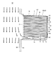
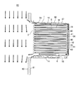
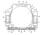
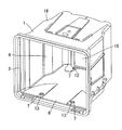
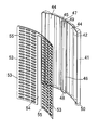
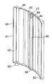
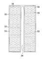
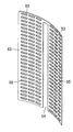
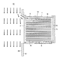
- FIG. 1 It is front explanatory drawing which shows typically the incomplete container main body in embodiment of the substrate storage container which concerns on this invention. It is a perspective explanatory view showing typically an incomplete container body in an embodiment of a substrate storage container concerning the present invention. It is a perspective explanatory view showing typically the vicinity of the attachment hole of the container body in the embodiment of the substrate storage container according to the present invention from below. It is a disassembled perspective view which shows typically the attachment hole of a container main body, an air supply valve, an offset adapter, etc. in embodiment of the board
- a substrate main body 1 capable of storing a plurality of semiconductor wafers W is used as a substrate storage container in the present embodiment.
- a lid 30 that is detachably fitted to the open front surface 2 of the container body 1, a locking mechanism 36 that locks the lid 30 fitted to the front surface 2 of the container body 1,
- a gas replacement unit 40 that blows out a purge gas for the semiconductor wafer W, which is a protective gas for the substrate supplied to the inside, to the inside of the container body 1, and supports the upper part of the housing 41 of the gas replacement unit 40 inside the container body 1.
- a plurality of blowout holes 55 for blowing out the purge gas are formed in the cover 52 of the gas replacement unit 40.
- each semiconductor wafer W is made of, for example, a ⁇ 300 mm silicon wafer having a thickness of 775 ⁇ m, and various semiconductor wafer manufacturing processes (up to 500 to 600 processes) are performed. Processing and processing are appropriately performed. 25 of the semiconductor wafers W are horizontally inserted and stored in the substrate storage area 5 defined in the container body 1 and aligned in the vertical direction at a predetermined interval.
- the container body 1, the lid body 30, and the locking mechanism 36 are constituted by a combination of a plurality of parts, each of which is injection-molded with a molding material containing a required resin.
- the resin contained in the molding material include thermoplastic resins such as cycloolefin polymer, cycloolefin copolymer, polycarbonate, polypropylene, polyetherimide, polyether ketone, polyether ether ketone, polybutylene terephthalate, polyacetal, and liquid crystal polymer, and the like.
- the alloy etc. are mention
- the container body 1 is formed into a front open box type having an open front surface 2 and is gripped by a ceiling transport mechanism in a semiconductor manufacturing factory with the open front surface 2 facing horizontally. Then, it is transported between the processes, or is positioned and mounted on the load port 81 of the EFEM 80 that flows down a large amount of clean air (see the arrows in FIGS. 1 and 2) from the ceiling fan filter unit 82 to the floor. .
- the container body 1 is provided with a pair of left and right support pieces 3 for supporting the semiconductor wafer W substantially horizontally on the inner sides of the container body, in other words, on the inner surfaces of the both side walls.
- Position restricting portions 4 for restricting excessive insertion of W are integrally formed.
- the pair of left and right support pieces 3 are arranged at a predetermined pitch in the vertical direction of the container main body 1, and each support piece 3 is formed in an elongated plate shape that supports the side edge of the semiconductor wafer W.
- a step portion for restricting the semiconductor wafer W from jumping forward is integrally formed on the front surface of the semiconductor device.
- the plurality of support pieces 3 partition and form a substrate storage area 5 in most of the container body 1 as shown in FIGS. 1 and 2.
- a pair of uppermost support pieces 3 may support or not support a dummy wafer having substantially the same size as the semiconductor wafer W as necessary.
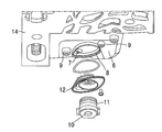
- Mounting holes 7 are drilled through both sides of the front and rear portions of the bottom plate 6 of the container body 1, and replacement air supply valves 10 and exhaust valves 13 are fitted into the mounting holes 7, respectively.
- the plurality of air supply valves 10 and the exhaust valves 13 cause a gas such as air or purge gas to flow inside and outside the container main body 1 to eliminate the internal / external pressure difference of the substrate storage container.
- endless eccentric walls 8 are provided around the mounting holes 7 on both sides of the rear portion of the bottom plate 6 so as to draw a cam.
- a plurality of cylindrical shapes are provided around each eccentric wall 8.
- Mounting bosses 9 are formed to protrude at a predetermined interval.
- the air supply valve 10 is built in, for example, a cylindrical air supply housing 11 so that a valve body can be moved up and down via a spring, and an internal gas replacement unit 40 from the outside of the container body 1.
- a purge gas see arrows in FIGS. 1 and 2.
- An offset adapter 12 that is fitted into the eccentric wall 8 via an O-ring is fitted to the upper portion of the air supply housing 11, and both side portions of the offset adapter 12 are screwed to the plurality of mounting bosses 9.
- the offset adapter 12 is formed, for example, in the shape of a hollow convex character having a substantially elliptical plane shape, and the protruding upper portion is opened and fitted into the mounting hole 7 of the bottom plate 6.
- the exhaust valve 13 is basically configured in the same manner as the air supply valve 10 and is closely fitted in the mounting holes 7 on both sides of the front portion of the bottom plate 6.
- the exhaust valve 13 functions to exhaust air from the inside of the container body 1 to the outside when the lid 30 is fitted to the front surface 2 of the container body 1 and purge gas is supplied.
- the purge gas include various inert gases and dry air.
- a separate bottom plate 14 serving as an interface is generally screwed horizontally to the back surface of the bottom plate 6 of the container body 1 via a screw tool.
- Positioning tools 15 for positioning the container main body 1 are provided.
- Each positioning tool 15 is basically formed in a substantially V-shaped cross section having a substantially elliptical shape in a plane, and a recess having a pair of inclined surfaces is directed downward, and the positioning pin of the load port 81 has a recess from above.
- the container body 1 is positioned with high accuracy by fitting and sliding contact.
- a transfer top flange 17 gripped by a ceiling transport mechanism of a semiconductor manufacturing factory is detachably mounted.
- Locking holes for the locking mechanism 36 are respectively drilled on both sides.
- the back wall 18 of the container body 1 is slightly curved with transparency that allows the inside of the container body 1 to be visually recognized, and has a scale that contributes to storage of the semiconductor wafer W on both sides of the inner surface. A required number of numbers are formed, and a pair of left and right locking pieces 19 for the gas replacement unit 40 are formed to protrude toward the front two directions of the container body 1 at the upper center of the inner surface.
- Such a back wall 18 of the container main body 1 is formed separately from the container main body 1 and is later attached to and integrated with the opened back surface of the molded container main body 1, but if necessary, a transparent container When the main body 1 is molded, it is integrally molded as a part of the container main body 1 or insert molded.
- a grip part 20 for gripping operation is detachably attached to the center part of the outer surface of both side walls of the container body 1. Moreover, the side rails 21 for conveyance are each selectively mounted horizontally on the lower outer surface of both side walls.
- the lid 30 includes a lid body 31 that is press-fitted into the front surface 2 of the container main body 1 and is fitted and a surface plate that covers the front surface of the lid body 31 that is opened. 33 and a sealing gasket 35 for sealing and sealing interposed between the inner periphery of the front surface 2 of the container main body 1 and the lid main body 31, and the inner periphery of the front surface 2 of the container main body 1 opened on the inner periphery of the lid main body 31.
- the peripheral wall comes into contact.
- the lid body 31 is basically formed in a substantially dish-shaped cross section with a shallow bottom, and a plurality of reinforcing and mounting ribs are disposed inside, and on the back surface, which is the facing surface facing the semiconductor wafer W, A front retainer 32 that elastically holds the semiconductor wafer W is mounted.
- a frame-shaped fitting groove is formed in the peripheral edge of the back surface of the lid body 31, and a seal gasket 35 that presses against the inner periphery of the front surface 2 of the container body 1 is tightly fitted in the fitting groove. Further, in both the upper and lower sides of the peripheral wall of the lid main body 31, a protruding / retracting hole for the locking mechanism 36 that faces the locking hole of the container main body 1 is penetrated and drilled.
- the surface plate 33 is formed in a horizontally long front rectangle, and a plurality of reinforcing and mounting ribs, screw holes, and the like are provided. On both sides of the surface plate 33, operation holes 34 for the locking mechanism 36 are respectively drilled.
- the seal gasket 35 is formed into a frame shape that can be elastically deformed using, for example, a polyester-based, polystyrene-based, polyolefin-based thermoplastic elastomer having excellent heat resistance, weather resistance, or the like as a molding material.
- the locking mechanism 36 is a pair of left and right rotating plates that are pivotally supported by the left and right side portions of the lid body 31 of the lid 30 and are rotated by the operation keys of the load port 81 that penetrates the operation holes 34 of the surface plate 33 from the outside. And a plurality of advancing and retracting plates that slide in the vertical direction of the lid body 30 as each rotating plate rotates, and as the respective advancing and retracting plates slide, they appear and retract from the intruding holes of the lid main body 31 to the locking holes of the container body 1. It comprises a plurality of locking claws that come in contact with and separate from each other, and is interposed between the lid body 31 and the surface plate 33.
- the gas replacement unit 40 allows the purge gas that has flowed from the air supply valve 10 to face the curved back wall 18 of the container body 1.
- An air conditioning plate 57 facing the plate 16 from the inside and below is provided.
- the housing 41 is formed into a slightly curved sectional dish shape having a shallow bottom using a predetermined molding material, in other words, a slightly curved box shape having a shallow bottom, and the front surface 42 is opened vertically to open the container body 1. It is directed in the front two directions and the semiconductor wafer W direction.
- the molding material of the housing 41 is not particularly limited, and examples thereof include cycloolefin polymer, cycloolefin copolymer, polypropylene, and polycarbonate. Among these, when the housing 41 is required to have transparency, high barrier properties, low impurity characteristics, etc., a cycloolefin polymer or a cycloolefin copolymer is preferably used.
- Carbon black, acetylene black, carbon fiber, carbon nanotube, carbon nanofiber, or the like is added to the molding material of the housing 41 as necessary.
- the housing 41 can be surface-treated with a conductive polymer such as polythiophene or polypyrrole, or can be provided with conductivity by applying a conductive paint.
- the container body 1, the air supply valve 10, and the offset adapter 12 are all provided with conductivity, and the surface resistance value of the housing 41 is in the range of 10 3 to 10 12 ⁇ . Is preferred.
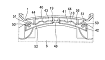
- the housing 41 is extended in the vertical direction of the container body 1 so that the curved back-and-back wall can face at least most of the curved back wall 18 of the container body 1.
- the air gap 43 for the gas flow passage 60 is defined between the inner surface of the container body 1 and the inner surface thereof.
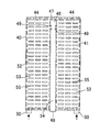
- the inside of the housing 41 member is partitioned into a pair of adjacent left and right storage spaces 44, and each storage space 44 is formed in a vertically long shape, and the storage space 44 serves as a chamber chamber to stabilize the purge gas flowing from the air supply valve 10. Or exert a mute effect.
- An observation window 46 with ribs 45 that allows the semiconductor wafer W to be visually recognized is vertically defined between the upper and lower portions of the pair of storage spaces 44, and the upper portion 47 of the pair of storage spaces 44 communicates.
- the upper space 47 between the pair of storage spaces 44 allows the purge gas flowing from the air supply valve 10 to flow as a flow path from the storage space 44 to the adjacent storage space 44, equalizing the pressure of the purge gas and blowing out from the storage space 44. It works to even out the amount.
- the lower space 48 between the pair of storage spaces 44 is bent into a thin channel shape, and connects and reinforces the adjacent storage spaces 44 and 44. Further, on both upper sides of the peripheral edge portion of the observation window 46, rearwardly-engaging engagement pieces 49 are formed to project, and a plurality of engagement pieces 49 project forward from the back wall 18 of the container body 1.
- the locking piece 19 is nipped and locked via a locking tool. Due to the locking of the engaging pieces 49, the upper part of the gas replacement unit 40 is firmly supported and fixed to the back wall 18 of the container body 1.
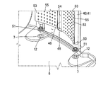
- purge gas flow tube portions 50 communicating with the storage space 44 are formed so as to protrude downward, and each flow tube portion 50 is formed in a cylindrical shape inside the mounting hole 7 of the bottom plate 6.
- the offset adapter 12 is fitted and connected to the upper portion of the offset adapter 12 via an elastic seal member 51 without a gap, and the purge gas from the air supply valve 10 flows into each flow tube portion 50.
- the seal member 51 is formed into a hollow convex shape or the like by using, for example, a fluorine-based molding material having excellent heat resistance, weather resistance, chemical resistance, and the like.
- the cover 52 is formed in a shape corresponding to the housing 41 using a predetermined material having flexibility as shown in FIGS. 12, 14, 16, 17, and the like. It is covered without gaps by the method such as heat welding or ultrasonic welding.
- the material of the cover 52 is not particularly limited, and examples thereof include molded articles and sheets such as cycloolefin polymer, cycloolefin copolymer, polypropylene, and polycarbonate. Among these, when the cover 52 requires transparency, high barrier properties, low impurity characteristics, etc., a sheet or film made of cycloolefin polymer or cycloolefin copolymer having a thickness of 1 to 1.5 mm is optimal. It is.
- the cover 52 may be surface-treated with a conductive polymer such as polythiophene or polypyrrole, or may be provided with conductivity by applying a conductive paint.
- the conductive polymer can ensure transparency and visibility, it is optimal when such transparency and visibility are required. Further, when conductivity is imparted to the cover 52, conductivity is imparted to the container body 1, the air supply valve 10, and the offset adapter 12 from the viewpoint of dissipating static electricity, and the surface resistance value of the cover 52 is 10 3. It is preferably within the range of ⁇ 10 12 ⁇ .
- the cover 52 is partitioned into a pair of adjacent left and right cover regions 53 so as to correspond to the partition structure of the housing 41, and each cover region 53 is formed in a vertically long shape to cover the storage space 44 of the housing 41.
- a notch 54 corresponding to the observation window 46 of the housing 41 is formed between the pair of cover areas 53 so that the upper portions of the adjacent cover areas 53 and the cover areas 53 are connected and integrated.
- a plurality of blowout holes 55 for blowing the purge gas in the housing 41 in the two front directions of the container main body 1 to contact the semiconductor wafer W are aligned and drilled.
- the notch 54 is formed in a vertically long shape and is covered without gaps on the rib 45 protruding forward from the peripheral edge of the observation window 46 by a method such as thermal welding or ultrasonic welding.
- the plurality of blow holes 55 are arranged in an m ⁇ n matrix, for example, in the vertical and horizontal directions of each cover region 53 so that the purge gas blows over a wide range and comes into contact with the plurality of semiconductor wafers W.
- a predetermined shape such as a front circular shape, an elliptical shape, a rectangular shape, a polygonal shape, a slot, or the like.
- the blow holes 55 other than the lowermost blow hole 55 and the blow holes 55 are adjusted so that the purge gas flows between the plurality of semiconductor wafers W from the viewpoint of preventing the purge gas from staying. Is done.
- the lowermost blowout hole 55 has a perforation position so that the purge gas does not come into contact with the lower surface of the lowermost semiconductor wafer W from the viewpoint of preventing mixing of the downflowed clean air and the blown purge gas. Is adjusted.
- the perforation position of the uppermost blow hole 55 is adjusted so that the purge gas does not contact the upper surface of the uppermost semiconductor wafer W in order to prevent mixing of clean air and the blown purge gas.
- each filter 56 is formed in a vertically long shape corresponding to the cover 52 using a predetermined material having flexibility, transparency, or translucency, and faces the front surface 42 of the housing 41.
- the cover 52 is covered without gaps by a method such as heat welding or ultrasonic welding on the back surface of the cover 52, specifically, the peripheral portion of each cover region 53 and the peripheral portion of each blowout hole 55, and is stored in the housing 41. Remove contaminants in the purge gas.
- the material of the filter 56 is not particularly limited. For example, a combination of polypropylene, polyester, non-woven fabric, nylon 66, and saran fiber is applicable.
- the air conditioning plate 57 is molded into a flat plate whose rear portion is curved in a semicircular shape using a molding material such as polycarbonate or polypropylene. It is supported and fixed horizontally on the uppermost pair of support pieces 3 and the housing 41 that can support the wafer.
- the air conditioning plate 57 is formed in a size corresponding to the ceiling plate 16 of the container body 1 and faces the uppermost semiconductor wafer W from above. From the front part to the center part of the surface of the air conditioning plate 57, a guide 58 for diverting the clean air to the left and right and for merging the clean air from the left and right is bent and formed in a plane V shape. Is directed toward the back wall 18 of the container body 1 and the housing 41.
- the air conditioning plate 57 is opposed to the inner surface of the ceiling plate 16 of the container body 1, and defines a gap 59 between the inner surface of the ceiling plate 16. 59 is in communication with the gap 43 between the inner surface of the back wall 18 of the container body 1 and the housing 41, and the gap 59 and the gap 43 are located outside the substrate storage area 5 of the container body 1 for clean air.
- the flow passage 60 is formed in an inverted L-shaped cross section.
- the container body of the substrate storage container is connected to the load port 81 of the EFEM 80. 1 is mounted, and the lid 30 is removed from the front surface 2 of the container body 1, and then a large amount of clean air is flowed down from the fan filter unit 82 on the ceiling of the EFEM 80 toward the floor, and from the outside of the container body 1.
- a purge gas is supplied inside at high pressure.
- a part of the clean air also flows into the upper part of the opening of the container body 1 near the front, but in this case, the clean air is caused by the merging action of the guide 58 of the air conditioning plate 57, After joining the guide 58, the gas flows through the gas flow path 60 on the ceiling plate 16 side of the container body 1 and the gas flow path 60 on the back wall 18 side of the container body 1, and flows from the rear below the interior of the container body 1. After flowing forward, it is exhausted outside the front of the container body 1 (see FIG. 2).
- the purge gas flows into the housing 41 of the gas replacement unit 40 from the air supply valve 10 of the container body 1 and is stored, passes through the filter 56, and opens from the plurality of outlet holes 55 of the cover 52. It blows out in two directions, and flows while coming into contact with the front part from the rear part between the plurality of semiconductor wafers W. Due to the flow of the purge gas, the air in the container body 1 is exhausted to the outside of the front surface of the container body 1, and the relative humidity in the container body 1 is lowered to a certain level or less.
- the purge gas flows so as to come into contact with the upper surface of the lowermost semiconductor wafer W and the lower surface of the uppermost semiconductor wafer W, and the lower surface of the lowermost semiconductor wafer W and the upper surface of the uppermost semiconductor wafer W. (See FIG. 1 and FIG. 2), it does not collide with clean air flowing in the container body 1 and does not mix with clean air to generate starch S.
- the purge gas flows from the wide area on the back wall 18 side of the container body 1 in the front direction, so that collision with clean air and stagnation S are prevented, and the inside of the container body 1 is efficiently replaced with the purge gas.
- the upper part of the housing 41 is supported and fixed to the container body 1, so that, for example, purge gas is supplied from the outside to the inside of the container body 1 at a high pressure, or the substrate storage container is conveyed at high speed. Even if vibration or acceleration is applied, the upper part of the gas replacement unit 40 does not shake back and forth and right and left, and the posture of the gas replacement unit 40 does not become unstable. Therefore, since the position of the blowing hole 55 of the gas replacement unit 40 does not deviate from the initial set position, the air in the container body 1 can be efficiently replaced with the purge gas.
- the container main body 1 when replacing the purge gas with the EFEM 80 and reducing the relative humidity of the substrate storage container uniformly below a certain level, the container main body 1 is designed so that a large amount of clean air from the ceiling bypasses the substrate storage region 5. Since the air can be exhausted from the front upper side of the container body 1 to the outside through the gas flow passage 60 from the inside lower side of the container, clean air flows into the lower side of the opened front side and collides with the purge gas, and the stagnation S is generated. There is nothing. Accordingly, the purge gas can reach the lower portion of the container main body 1 near the front surface, and can be efficiently replaced, or the relative humidity between the lower portion in the container main body 1 and the rest can be made uniform. The relative humidity inside can be lowered uniformly below a certain level.
- the container body 1 since a large amount of clean air from the ceiling can be exhausted from the front lower side of the container body 1 to the outside through the gas flow passage 60 of the container body 1 through the inside lower side, the container body 1 is close to the opened front side. Clean air flows into the upper part of the air and collides with the purge gas, so that no stagnation S occurs. This allows the purge gas to reach a wide space between the ceiling plate 16 of the container body 1 and the uppermost semiconductor wafer W for efficient replacement, and uniform relative humidity between the upper part of the container body 1 and the rest of the container body 1. Therefore, the relative humidity in the container body 1 can be uniformly lowered below a certain level.
- the cover 52 that covers the front surface 42 of the housing 41 can be removed not by welding but by adhesion or the like, it is possible to easily select the cover 52 having the blowout hole 55 that is optimal for the semiconductor manufacturing process. It becomes. Further, since the air supply valve 10 and the flow tube portion 50 of the housing 41 are connected via the offset adapter 12 and the seal member 51, the air supply valve 10 and the flow tube portion 50 of the housing 41 are separated and eccentric. However, it is possible to securely connect and fix them. Further, if an elastic seal member 51 is used, it is possible to facilitate the connection and fixation, and to easily form a seal.
- the housing 41 and the cover 52 of the gas replacement unit 40 are formed of a conductive material, static electricity can be dissipated. Therefore, it is possible to effectively prevent the gas replacement unit 40 from being charged and increase particles due to the vibration accompanying the ejection of the purge gas. By preventing the increase of the particles, the possibility of contamination of the semiconductor wafer W is effectively eliminated. can do. Furthermore, since the static electricity charged from the contact portion (such as the engagement piece 49) between the container main body 1 and the gas replacement unit 40 can be grounded to the outside via the container main body 1, particles can be further reduced.
- FIGS. 19 to 22 show a second embodiment of the present invention.
- the opened front surface 42 of the housing 41 of the gas replacement unit 40 is directed toward the curved rear wall 18 of the container body 1.
- a closed rear wall of the housing 41 is directed in the two directions of the front surface of the container body 1, a plurality of blow holes 55 are formed side by side in the closed back wall of the housing 41, and the front face 42 of the housing 41 is covered with no blow holes. 52.
- the container body 1 and the gas replacement unit 40 are each provided with conductivity, and at least one of the rear wall 18 of the container body 1, the upper both sides of the housing 41, and the upper both sides of the cover 52 is replaced with the gas.
- a small contact protrusion 61 is provided to contact and conduct with the unit 40.
- the cover 52 is divided into a pair of adjacent left and right cover regions 53 so as to correspond to the partition structure of the housing 41, and each cover region 53 is formed in a vertically long shape to cover the storage space 44 of the housing 41.
- the other parts are the same as those in the above embodiment, and the description thereof is omitted.
- the same effect as the above embodiment can be expected, and since the plurality of blowing holes 55 are perforated not in the cover 52 but in the back wall of the housing 41, the configuration of the gas replacement unit 40 can be diversified. It is clear that it can be achieved.
- the some support piece 3 in the said embodiment may be integrally formed in the inner surface of the both-sides wall of the container main body 1, and may be positioned and attached to the inner surface of the both-sides wall of the container main body 1 so that attachment or detachment is possible later.
- the single gas replacement unit 40 was made to oppose the back wall 18 of the container main body 1
- the several gas replacement unit 40 was made to oppose the back wall 18 of the container main body 1, and this some gas replacement
- a gap may be formed between the units 40, and the gap may be used as an observation window 46 that enables the semiconductor wafer W to be visually recognized.
- the housing 41 may be formed in a size that can be opposed to the entire back wall 18 of the container body 1, or may be formed in a size that can be opposed to a part of the back wall 18 of the container body 1. .
- the lower portions 48 of the pair of storage spaces 44 may communicate with each other, or the upper and lower portions of the pair of storage spaces 44 may communicate with each other.
- the engagement piece 49 located on both upper sides of the peripheral edge of the observation window 46 is engaged with the engagement piece 19 protruding from the back wall 18 of the container body 1, and the gas replacement unit 40 is attached to the back wall 18 of the container body 1.
- the upper part is supported and fixed, the present invention is not limited to this.
- the engagement piece 49 at the center on both sides of the peripheral edge of the observation window 46 and the locking piece 19 protruding from the back wall 18 of the container body 1 are locked, and the gas replacement unit 40 is placed on the back wall 18 of the container body 1.
- the central portion may be supported and fixed, or the engaging pieces 49 may be protruded from the upper and central portions on both sides of the peripheral edge of the observation window 46, and the upper portion and the center of the gas replacement unit 40 may be placed on the back wall 18 of the container body 1. It is also possible to support and fix the part.
- the distribution cylinder portion 50 of the housing 41 can be formed in various shapes such as a polygon. Further, a rectifying member that extends while tilting toward the rear side of the side wall of the container main body 1 is supported on both sides of the housing 41, and the tip of each rectifying member is brought close to the inner surface of the rear side of the side wall of the container main body 1 through a gap. It is possible to use the gap as a gas flow path 60 for clean air or a cleaning flow path using a cleaning liquid. Furthermore, the cover 52 is not limited to a flexible sheet, but may be a resin molded product using various resins.
- the substrate storage container according to the present invention is used in the field of manufacturing semiconductors and liquid crystal displays.
Landscapes
- Container, Conveyance, Adherence, Positioning, Of Wafer (AREA)
- Packaging Frangible Articles (AREA)
Abstract
Description
気体置換ユニットは、給気弁から流入した基板用保護気体を貯留するハウジング部材と、このハウジング部材の開口面を覆うカバー部材とを含み、ハウジング部材の下部を基板用保護気体が流通するよう給気弁に接続し、ハウジング部材とカバー部材のいずれか一方に、ハウジング部材内の基板用保護気体を容器本体の正面方向に吹き出す複数の吹出孔を設けたことを特徴としている。
また、気体置換ユニットのハウジング部材の開口した正面を容器本体の背面壁方向に向けてハウジングの閉じた背面壁を容器本体の正面方向に向け、ハウジング部材の背面壁に複数の吹出孔を設け、ハウジング部材の正面を吹出孔無のカバー部材により覆うことができる。
気体置換ユニットのハウジング部材を容器本体の上下方向に伸ばしてその大きさを容器本体の背面壁の少なくとも大部分に対向可能な大きさとし、ハウジング部材の内部を複数の貯留空間に区画し、この複数の貯留空間の間に基板視認用の観察窓を形成するとともに、複数の貯留空間の上部間と下部間の少なくともいずれか一方を基板用保護気体が流通するよう連通させ、
気体置換ユニットのカバー部材に、ハウジング部材の観察窓に対応する切り欠きを形成し、カバー部材の縦横方向に複数の吹出孔を配列することもできる。
また、気体置換ユニットは、容器本体の底部と天井のうち、少なくとも天井との間に隙間を区画するよう対向する整風板部材を含み、この整風板部材が区画する隙間を容器本体の背面壁内面とハウジング部材との間の空隙と連通させて気体流通路とし、カバー部材の複数の吹出孔のうち、下方の吹出孔の位置を、最下方に位置する基板の下面に基板用保護気体が触れないよう調整することが可能である。
また、気体置換ユニットを導電材料により形成し、この気体置換ユニットの容器本体との接続部により、気体置換ユニットの静電気を容器本体の外部に接地可能とすることが可能である。
また、気体置換ユニットは、ハウジング部材とカバー部材との間に介在される通気性のフィルタ部材を含むと良い。
また、容器本体の背面壁の内面上部に、気体置換ユニット用の係止片を容器本体の正面方向に向けて形成し、ハウジング部材の観察窓の周縁部上方に、容器本体の背面壁の係止片と接続される係合片を形成することもできる。
また、気体置換ユニットの整風板部材に、気体用のガイドを平面V字形状に形成し、このガイドの屈曲部を容器本体の背面壁方向に向けても良い。
カバー52は、ハウジング41の区画構造に対応するよう、隣接する左右一対のカバー領域53に分割され、各カバー領域53が縦長に形成されてハウジング41の貯留空間44を被覆する。その他の部分については、上記実施形態と同様であるので説明を省略する。
2 正面
3 支持片
5 基板収納領域
6 底板(底部)
7 取付孔
10 給気弁
13 排気弁
16 天井板(天井)
18 背面壁
19 係止片
30 蓋体
36 施錠機構
40 気体置換ユニット
41 ハウジング(ハウジング部材)
42 正面
43 空隙
44 貯留空間
46 観察窓
47 一対の貯留空間の上部間(複数の貯留空間の上部間)
48 一対の貯留空間の下部間(複数の貯留空間の下部間)
49 係合片
50 流通筒部
52 カバー(カバー部材)
53 カバー領域
54 切り欠き
55 吹出孔
56 フィルタ(フィルタ部材)
57 整風板(整風板部材)
59 隙間
60 気体流通路
61 接触突起
80 EFEM
82 ファンフィルターユニット
S 澱み
W 半導体ウェーハ(基板)
Claims (9)
- 複数枚の基板を収納可能な容器本体と、この容器本体の外部から内部に基板用保護気体を供給する給気弁と、この給気弁からの基板用保護気体を容器本体の内部に吹き出す気体置換ユニットとを備え、容器本体をフロントオープンボックスに形成してその底部後方に給気弁を取り付けた基板収納容器であって、
気体置換ユニットは、給気弁から流入した基板用保護気体を貯留するハウジング部材と、このハウジング部材の開口面を覆うカバー部材とを含み、ハウジング部材の下部を基板用保護気体が流通するよう給気弁に接続し、ハウジング部材とカバー部材のいずれか一方に、ハウジング部材内の基板用保護気体を容器本体の正面方向に吹き出す複数の吹出孔を設けたことを特徴とする基板収納容器。 - 気体置換ユニットのハウジング部材の開口面を正面とし、このハウジング部材の開口した正面を容器本体の正面方向に向け、ハウジング部材の正面をカバー部材により覆うとともに、このカバー部材に複数の吹出孔を設けた請求項1記載の基板収納容器。
- 容器本体に複数枚の基板を上下方向に並べて収納可能とし、この容器本体の少なくとも背面壁に透明性を付与し、
気体置換ユニットのハウジング部材を容器本体の上下方向に伸ばしてその大きさを容器本体の背面壁の少なくとも大部分に対向可能な大きさとし、ハウジング部材の内部を複数の貯留空間に区画し、この複数の貯留空間の間に基板視認用の観察窓を形成するとともに、複数の貯留空間の上部間と下部間の少なくともいずれか一方を基板用保護気体が流通するよう連通させ、
気体置換ユニットのカバー部材に、ハウジング部材の観察窓に対応する切り欠きを形成し、カバー部材の縦横方向に複数の吹出孔を配列した請求項2記載の基板収納容器。 - 気体置換ユニットのハウジング部材の上部と中央部の少なくともいずれか一方を容器本体の内部に支持させた請求項1、2、又は3記載の基板収納容器。
- 気体置換ユニットは、容器本体の背面壁内面との間に空隙を形成するよう配置され、容器本体の底部と天井のうち、少なくとも天井との間に隙間を区画するよう対向する整風板部材を含み、この整風板部材が区画する隙間を空隙と連通させて気体流通路とし、カバー部材の複数の吹出孔のうち、下方の吹出孔の位置を、最下方に位置する基板の下面に基板用保護気体が触れないよう調整した請求項2、3、又は4記載の基板収納容器。
- 気体置換ユニットの複数の吹出孔のうち、上方の吹出孔の位置を、最上方に位置する基板の上面に基板用保護気体が触れないよう調整した請求項1ないし5いずれか一項に記載の基板収納容器。
- 気体置換ユニットを導電材料により形成し、この気体置換ユニットの容器本体との接続部により、気体置換ユニットの静電気を容器本体の外部に接地可能とした請求項1ないし6いずれか一項に記載の基板収納容器。
- 気体置換ユニットを導電材料により形成してその表面抵抗値を103~1012Ωの範囲内とした請求項1ないし8いずれか一項に記載の基板収納容器。
- 気体置換ユニットは、ハウジング部材とカバー部材との間に介在される通気性のフィルタ部材を含んでなる請求項1ないし8いずれか一項に記載の基板収納容器。
Priority Applications (6)
| Application Number | Priority Date | Filing Date | Title |
|---|---|---|---|
| JP2016535930A JP6532466B2 (ja) | 2014-07-25 | 2015-07-21 | 基板収納容器 |
| US15/329,078 US10312122B2 (en) | 2014-07-25 | 2015-07-21 | Substrate storage container |
| CN201580040567.4A CN106537574B (zh) | 2014-07-25 | 2015-07-21 | 基板收纳容器 |
| SG11201700505UA SG11201700505UA (en) | 2014-07-25 | 2015-07-21 | Substrate storage container |
| KR1020177004770A KR102397525B1 (ko) | 2014-07-25 | 2015-07-21 | 기판 수납 용기 |
| DE112015003423.4T DE112015003423T5 (de) | 2014-07-25 | 2015-07-21 | Substratvorratsbehälter |
Applications Claiming Priority (2)
| Application Number | Priority Date | Filing Date | Title |
|---|---|---|---|
| JP2014-151855 | 2014-07-25 | ||
| JP2014151855 | 2014-07-25 |
Publications (1)
| Publication Number | Publication Date |
|---|---|
| WO2016013536A1 true WO2016013536A1 (ja) | 2016-01-28 |
Family
ID=55163061
Family Applications (1)
| Application Number | Title | Priority Date | Filing Date |
|---|---|---|---|
| PCT/JP2015/070655 Ceased WO2016013536A1 (ja) | 2014-07-25 | 2015-07-21 | 基板収納容器 |
Country Status (8)
| Country | Link |
|---|---|
| US (1) | US10312122B2 (ja) |
| JP (1) | JP6532466B2 (ja) |
| KR (1) | KR102397525B1 (ja) |
| CN (1) | CN106537574B (ja) |
| DE (1) | DE112015003423T5 (ja) |
| SG (1) | SG11201700505UA (ja) |
| TW (1) | TWI661503B (ja) |
| WO (1) | WO2016013536A1 (ja) |
Cited By (11)
| Publication number | Priority date | Publication date | Assignee | Title |
|---|---|---|---|---|
| JP2017112165A (ja) * | 2015-12-15 | 2017-06-22 | 信越ポリマー株式会社 | 基板収納容器 |
| JP2018120912A (ja) * | 2017-01-24 | 2018-08-02 | 信越ポリマー株式会社 | 基板収納容器及び基板収納容器の製造方法 |
| WO2018179964A1 (ja) * | 2017-03-27 | 2018-10-04 | 信越ポリマー株式会社 | 基板収納容器 |
| WO2018203384A1 (ja) * | 2017-05-02 | 2018-11-08 | ミライアル株式会社 | 基板収納容器 |
| JP2022119995A (ja) * | 2016-08-30 | 2022-08-17 | ブルックス オートメーション (ジャーマニー) ゲゼルシャフト ミット ベシュレンクテル ハフツング | レチクル容器及び拡散板 |
| JP2022150855A (ja) * | 2021-03-26 | 2022-10-07 | 信越ポリマー株式会社 | 基板収納容器 |
| JP2023007441A (ja) * | 2021-06-30 | 2023-01-18 | 家登精密工業股▲ふん▼有限公司 | 基板容器システム |
| CN117465827A (zh) * | 2022-07-27 | 2024-01-30 | 家登精密工业股份有限公司 | 上开式载板载具 |
| JP2024025617A (ja) * | 2022-08-11 | 2024-02-26 | 家登精密工業股▲ふん▼有限公司 | 負圧チャンバ内蔵の基板容器 |
| JP2024522578A (ja) * | 2021-06-08 | 2024-06-21 | インテグリス・インコーポレーテッド | ウエハ容器およびパージシステム |
| JP7537570B1 (ja) | 2023-08-22 | 2024-08-21 | artience株式会社 | 電気電子包装材用熱可塑性樹脂組成物および電気電子包装材 |
Families Citing this family (24)
| Publication number | Priority date | Publication date | Assignee | Title |
|---|---|---|---|---|
| KR101865636B1 (ko) * | 2016-07-06 | 2018-06-08 | 우범제 | 웨이퍼 수납용기 |
| WO2018047541A1 (ja) * | 2016-09-06 | 2018-03-15 | 信越ポリマー株式会社 | 基板収納容器及び気体置換ユニット |
| JP6623988B2 (ja) * | 2016-09-09 | 2019-12-25 | 株式会社ダイフク | 容器収納設備 |
| US10115607B2 (en) * | 2016-09-16 | 2018-10-30 | Applied Materials, Inc. | Method and apparatus for wafer outgassing control |
| US10262884B2 (en) | 2016-11-10 | 2019-04-16 | Applied Materials, Inc. | Systems, apparatus, and methods for an improved load port |
| KR102066175B1 (ko) * | 2017-12-28 | 2020-01-14 | 우범제 | 웨이퍼 수납용기 |
| US10937677B2 (en) * | 2018-04-02 | 2021-03-02 | Bum Je WOO | Wafer storage container |
| WO2019194327A1 (ko) * | 2018-04-02 | 2019-10-10 | 우범제 | 웨이퍼 수납용기 |
| WO2020065968A1 (ja) * | 2018-09-28 | 2020-04-02 | ミライアル株式会社 | 基板収納容器 |
| JP7299474B2 (ja) * | 2019-03-13 | 2023-06-28 | シンフォニアテクノロジー株式会社 | Efem |
| CN112289718A (zh) * | 2019-07-13 | 2021-01-29 | 家登精密工业股份有限公司 | 基板载具及其气体扩散模块 |
| US11104496B2 (en) * | 2019-08-16 | 2021-08-31 | Gudeng Precision Industrial Co., Ltd. | Non-sealed reticle storage device |
| KR102272005B1 (ko) * | 2019-10-17 | 2021-07-02 | (주)에스티아이 | 풉 세정 장치 |
| TWI751814B (zh) * | 2020-09-22 | 2022-01-01 | 家登精密工業股份有限公司 | 支撐片狀物的中央支撐裝置及存放片狀物的儲存設備 |
| JP7591919B2 (ja) * | 2020-12-16 | 2024-11-29 | キヤノン株式会社 | 収納装置、露光装置及び物品の製造方法 |
| JP7467367B2 (ja) * | 2021-02-19 | 2024-04-15 | 信越ポリマー株式会社 | パネル収納容器 |
| CN116888721A (zh) * | 2021-03-29 | 2023-10-13 | 未来儿股份有限公司 | 基板收纳容器 |
| US12347711B2 (en) | 2021-08-17 | 2025-07-01 | Gudeng Precision Industrial Co., Ltd. | Gas diffusion device, and wafer container including the same |
| KR20240115341A (ko) | 2021-12-17 | 2024-07-25 | 엔테그리스, 아이엔씨. | 반도체 기판 운반 용기 내에 퍼지 유체 조절 요소를 설치하는 방법 |
| TWD223988S (zh) * | 2022-03-03 | 2023-03-01 | 家登精密工業股份有限公司 | 氣匣 |
| US12589345B2 (en) * | 2022-04-08 | 2026-03-31 | Applied Materials, Inc. | Filter isolation for reduced startup time in low relative humidity equipment front end module |
| CN117524953A (zh) * | 2023-03-23 | 2024-02-06 | 家登精密工业股份有限公司 | 气阀盖和应用气阀盖的基板载具 |
| WO2025024330A1 (en) * | 2023-07-21 | 2025-01-30 | Entegris, Inc. | Method and device to distribute gas into a container |
| CN118218326A (zh) * | 2024-03-14 | 2024-06-21 | 江苏芯梦半导体设备有限公司 | 一种基板存储容器清洁方法及清洁单元及清洁设备 |
Citations (4)
| Publication number | Priority date | Publication date | Assignee | Title |
|---|---|---|---|---|
| JPH09134952A (ja) * | 1995-11-03 | 1997-05-20 | Jenoptik Ag | ウェハ状物体の搬送コンテナ |
| JP2002122382A (ja) * | 2000-01-28 | 2002-04-26 | Ebara Corp | 基板容器 |
| JP2002170876A (ja) * | 2000-12-04 | 2002-06-14 | Ebara Corp | 基板搬送容器 |
| JP2013513951A (ja) * | 2009-12-10 | 2013-04-22 | インテグリス・インコーポレーテッド | 微小環境中に均一に分布した浄化ガスを得るための多孔質バリア |
Family Cites Families (14)
| Publication number | Priority date | Publication date | Assignee | Title |
|---|---|---|---|---|
| KR20010078077A (ko) * | 2000-01-28 | 2001-08-20 | 마에다 시게루 | 기판용기 |
| JP3960787B2 (ja) | 2001-11-30 | 2007-08-15 | 信越ポリマー株式会社 | 精密基板収納容器 |
| JP4201583B2 (ja) | 2002-11-28 | 2008-12-24 | 信越ポリマー株式会社 | 基板収納容器 |
| US6899145B2 (en) * | 2003-03-20 | 2005-05-31 | Asm America, Inc. | Front opening unified pod |
| JP4027837B2 (ja) | 2003-04-28 | 2007-12-26 | Tdk株式会社 | パージ装置およびパージ方法 |
| JP4920565B2 (ja) * | 2007-12-04 | 2012-04-18 | 株式会社アルバック | 基板収容容器及び基板処理方法 |
| CN102017119B (zh) * | 2008-03-13 | 2014-01-01 | 安格斯公司 | 具有管状环境控制部件的晶圆容器 |
| WO2011102318A1 (ja) * | 2010-02-19 | 2011-08-25 | 信越ポリマー株式会社 | 基板収納容器 |
| KR101368706B1 (ko) * | 2011-07-22 | 2014-02-28 | 주식회사 삼에스코리아 | 웨이퍼 캐리어 |
| JP6087161B2 (ja) * | 2012-02-03 | 2017-03-01 | 東京エレクトロン株式会社 | 基板収容容器のパージ方法 |
| TWI642605B (zh) * | 2012-11-20 | 2018-12-01 | 恩特葛瑞斯股份有限公司 | 具有清洗埠的基板收納盒 |
| TWM453233U (zh) * | 2013-01-07 | 2013-05-11 | 家登精密工業股份有限公司 | 應用於基板收納容器的氣體填充裝置 |
| JP6226190B2 (ja) * | 2014-02-20 | 2017-11-08 | Tdk株式会社 | パージシステム、及び該パージシステムに供せられるポッド及びロードポート装置 |
| US9881826B2 (en) * | 2014-10-24 | 2018-01-30 | Lam Research Corporation | Buffer station with single exit-flow direction |
-
2015
- 2015-07-21 DE DE112015003423.4T patent/DE112015003423T5/de not_active Withdrawn
- 2015-07-21 WO PCT/JP2015/070655 patent/WO2016013536A1/ja not_active Ceased
- 2015-07-21 JP JP2016535930A patent/JP6532466B2/ja active Active
- 2015-07-21 CN CN201580040567.4A patent/CN106537574B/zh active Active
- 2015-07-21 KR KR1020177004770A patent/KR102397525B1/ko active Active
- 2015-07-21 US US15/329,078 patent/US10312122B2/en active Active
- 2015-07-21 SG SG11201700505UA patent/SG11201700505UA/en unknown
- 2015-07-24 TW TW104124072A patent/TWI661503B/zh active
Patent Citations (4)
| Publication number | Priority date | Publication date | Assignee | Title |
|---|---|---|---|---|
| JPH09134952A (ja) * | 1995-11-03 | 1997-05-20 | Jenoptik Ag | ウェハ状物体の搬送コンテナ |
| JP2002122382A (ja) * | 2000-01-28 | 2002-04-26 | Ebara Corp | 基板容器 |
| JP2002170876A (ja) * | 2000-12-04 | 2002-06-14 | Ebara Corp | 基板搬送容器 |
| JP2013513951A (ja) * | 2009-12-10 | 2013-04-22 | インテグリス・インコーポレーテッド | 微小環境中に均一に分布した浄化ガスを得るための多孔質バリア |
Cited By (22)
| Publication number | Priority date | Publication date | Assignee | Title |
|---|---|---|---|---|
| JP2017112165A (ja) * | 2015-12-15 | 2017-06-22 | 信越ポリマー株式会社 | 基板収納容器 |
| JP2022119995A (ja) * | 2016-08-30 | 2022-08-17 | ブルックス オートメーション (ジャーマニー) ゲゼルシャフト ミット ベシュレンクテル ハフツング | レチクル容器及び拡散板 |
| EP4102549A1 (en) * | 2016-08-30 | 2022-12-14 | Brooks Automation (Germany) GmbH | Reticle compartment and diffusor plate |
| JP2018120912A (ja) * | 2017-01-24 | 2018-08-02 | 信越ポリマー株式会社 | 基板収納容器及び基板収納容器の製造方法 |
| KR102461290B1 (ko) * | 2017-03-27 | 2022-11-01 | 신에츠 폴리머 가부시키가이샤 | 기판 수납 용기 |
| US11646214B2 (en) | 2017-03-27 | 2023-05-09 | Shin-Etsu Polymer Co., Ltd. | Substrate storage container |
| JPWO2018179964A1 (ja) * | 2017-03-27 | 2020-02-06 | 信越ポリマー株式会社 | 基板収納容器 |
| KR20190129991A (ko) * | 2017-03-27 | 2019-11-20 | 신에츠 폴리머 가부시키가이샤 | 기판 수납 용기 |
| US20200020549A1 (en) * | 2017-03-27 | 2020-01-16 | Shin-Etsu Polymer Co., Ltd. | Substrate Storage Container |
| WO2018179964A1 (ja) * | 2017-03-27 | 2018-10-04 | 信越ポリマー株式会社 | 基板収納容器 |
| US11011399B2 (en) | 2017-05-02 | 2021-05-18 | Miraial Co., Ltd. | Substrate storing container |
| WO2018203384A1 (ja) * | 2017-05-02 | 2018-11-08 | ミライアル株式会社 | 基板収納容器 |
| JP2022150855A (ja) * | 2021-03-26 | 2022-10-07 | 信越ポリマー株式会社 | 基板収納容器 |
| JP7570264B2 (ja) | 2021-03-26 | 2024-10-21 | 信越ポリマー株式会社 | 基板収納容器 |
| JP2024522578A (ja) * | 2021-06-08 | 2024-06-21 | インテグリス・インコーポレーテッド | ウエハ容器およびパージシステム |
| JP2023007441A (ja) * | 2021-06-30 | 2023-01-18 | 家登精密工業股▲ふん▼有限公司 | 基板容器システム |
| JP7458442B2 (ja) | 2021-06-30 | 2024-03-29 | 家登精密工業股▲ふん▼有限公司 | 基板容器システム |
| CN117465827A (zh) * | 2022-07-27 | 2024-01-30 | 家登精密工业股份有限公司 | 上开式载板载具 |
| JP2024025617A (ja) * | 2022-08-11 | 2024-02-26 | 家登精密工業股▲ふん▼有限公司 | 負圧チャンバ内蔵の基板容器 |
| JP7506137B2 (ja) | 2022-08-11 | 2024-06-25 | 家登精密工業股▲ふん▼有限公司 | 負圧チャンバ内蔵の基板容器 |
| JP7537570B1 (ja) | 2023-08-22 | 2024-08-21 | artience株式会社 | 電気電子包装材用熱可塑性樹脂組成物および電気電子包装材 |
| JP2025029900A (ja) * | 2023-08-22 | 2025-03-07 | artience株式会社 | 電気電子包装材用熱可塑性樹脂組成物および電気電子包装材 |
Also Published As
| Publication number | Publication date |
|---|---|
| SG11201700505UA (en) | 2017-02-27 |
| TW201622047A (zh) | 2016-06-16 |
| JPWO2016013536A1 (ja) | 2017-05-25 |
| DE112015003423T5 (de) | 2017-05-04 |
| CN106537574A (zh) | 2017-03-22 |
| CN106537574B (zh) | 2020-06-05 |
| KR20170038846A (ko) | 2017-04-07 |
| TWI661503B (zh) | 2019-06-01 |
| US10312122B2 (en) | 2019-06-04 |
| KR102397525B1 (ko) | 2022-05-12 |
| JP6532466B2 (ja) | 2019-06-19 |
| US20170213752A1 (en) | 2017-07-27 |
Similar Documents
| Publication | Publication Date | Title |
|---|---|---|
| WO2016013536A1 (ja) | 基板収納容器 | |
| US10923373B2 (en) | Substrate storage container and gas replacement unit | |
| US11646214B2 (en) | Substrate storage container | |
| JP6400534B2 (ja) | 基板収納容器 | |
| JP5713875B2 (ja) | 基板収納容器 | |
| US10522379B2 (en) | Substrate transfer apparatus | |
| JP6431440B2 (ja) | 基板収納容器 | |
| JP6367153B2 (ja) | 基板収納容器 | |
| JP6265844B2 (ja) | 基板収納容器 | |
| JP5627509B2 (ja) | 基板収納容器 | |
| JP6271354B2 (ja) | 基板収納容器及びその製造方法 | |
| US11488850B2 (en) | Substrate storage container and gas replacement unit | |
| JP6553498B2 (ja) | 基板収納容器 | |
| JP2018198332A (ja) | 基板収納容器 | |
| JP6576811B2 (ja) | 基板収納容器 | |
| JP6165653B2 (ja) | 基板収納容器 | |
| US20090200250A1 (en) | Cleanliness-improved wafer container | |
| JP2011258624A (ja) | 基板収納容器 | |
| JP7423429B2 (ja) | 基板収納容器 | |
| JP7453822B2 (ja) | 基板収納容器 | |
| JP2017092229A (ja) | 基板収納容器 | |
| JP2012190898A (ja) | 基板収納容器 | |
| JP6549027B2 (ja) | 基板収納容器 | |
| JP2026022699A (ja) | 基板収納容器 |
Legal Events
| Date | Code | Title | Description |
|---|---|---|---|
| 121 | Ep: the epo has been informed by wipo that ep was designated in this application |
Ref document number: 15825091 Country of ref document: EP Kind code of ref document: A1 |
|
| ENP | Entry into the national phase |
Ref document number: 2016535930 Country of ref document: JP Kind code of ref document: A |
|
| WWE | Wipo information: entry into national phase |
Ref document number: 15329078 Country of ref document: US Ref document number: 112015003423 Country of ref document: DE |
|
| ENP | Entry into the national phase |
Ref document number: 20177004770 Country of ref document: KR Kind code of ref document: A |
|
| 122 | Ep: pct application non-entry in european phase |
Ref document number: 15825091 Country of ref document: EP Kind code of ref document: A1 |