WO2016013151A1 - 高炭酸飲料の供給装置 - Google Patents
高炭酸飲料の供給装置 Download PDFInfo
- Publication number
- WO2016013151A1 WO2016013151A1 PCT/JP2015/003094 JP2015003094W WO2016013151A1 WO 2016013151 A1 WO2016013151 A1 WO 2016013151A1 JP 2015003094 W JP2015003094 W JP 2015003094W WO 2016013151 A1 WO2016013151 A1 WO 2016013151A1
- Authority
- WO
- WIPO (PCT)
- Prior art keywords
- raw material
- material liquid
- nozzle
- container
- valve body
- Prior art date
- Legal status (The legal status is an assumption and is not a legal conclusion. Google has not performed a legal analysis and makes no representation as to the accuracy of the status listed.)
- Ceased
Links
Images








Classifications
-
- B—PERFORMING OPERATIONS; TRANSPORTING
- B67—OPENING, CLOSING OR CLEANING BOTTLES, JARS OR SIMILAR CONTAINERS; LIQUID HANDLING
- B67D—DISPENSING, DELIVERING OR TRANSFERRING LIQUIDS, NOT OTHERWISE PROVIDED FOR
- B67D1/00—Apparatus or devices for dispensing beverages on draught
- B67D1/04—Apparatus utilising compressed air or other gas acting directly or indirectly on beverages in storage containers
Definitions
- the present invention relates to an apparatus for supplying a carbonated drink obtained by mixing a drink liquid and a carbonated liquid, and more particularly, to an apparatus for supplying a high carbonated drink in which the carbon dioxide gas of the carbonate solution is difficult to escape.
- Patent Document 1 provides a beverage dispenser having a structure in which a base beverage (such as strawberry high) and an added syrup are simultaneously supplied from each nozzle to a cup.
- a base beverage such as strawberry high
- the base beverage nozzle and the additive syrup nozzle are arranged side by side in close proximity to the left and right, so the base beverage (such as strawberry high) and the additive syrup are discharged in the same direction. Is done.
- This beverage supply device is provided with a nozzle tube for discharging a liquid beverage and a discharge port of a dilution liquid nozzle for discharging a diluent at a predetermined distance from each other, and a beverage placed on a cuprest from each nozzle It is an apparatus for preparing by discharging a liquid raw material and a diluent into a container.
- the diluent outlet of the diluent nozzle is disposed so as to face the inner wall surface of the beverage container, and the diluent is discharged toward the inner wall surface to flow down.
- an object of the present invention is to provide a high carbonated beverage supply device in which the carbonic acid solution does not collide with the inner wall surface of the container and the carbonic acid gas escapes from the carbonic acid solution as much as possible.
- the present invention includes (1) a raw material liquid nozzle that pours out a raw material liquid, a carbonic acid liquid nozzle that pours out a carbonic acid liquid, and a receiving part on which the container is placed, and the raw material is placed in a container positioned by the guide part
- a high carbonated beverage supply device capable of discharging a raw material liquid and a carbonic acid liquid from a liquid nozzle and a carbonic acid liquid nozzle, respectively, provided so that the raw material liquid nozzle is located at the center of the container.
- the nozzle hole is arranged along the inner wall surface of the container, and the high carbonated beverage supply device is provided so that the discharge direction of the carbonic acid liquid is inclined at an angle ⁇ with respect to the horizontal tangential direction of the inner wall surface.
- the present invention resides in (2) the high carbonated beverage supply device according to the above (1), wherein the raw material liquid nozzle includes a plurality of holes for discharging the raw material liquid in multiple directions.
- the present invention resides in (3) the high carbonated beverage supply device according to the above (1) or (2), wherein the discharge direction of the carbonate nozzle is inclined by an angle ⁇ with respect to the inner wall surface of the container.
- the present invention includes (5) a cartridge reservoir that temporarily stores a certain amount (one shot) of the raw material liquid, and the cartridge reservoir is connected to the raw material liquid tank via the raw material liquid supply channel.
- the cartridge reservoir is connected to the raw material liquid nozzle through the raw material liquid discharge passage, and discharges a predetermined amount (one shot) of the raw material liquid from the cartridge reservoir from the raw material liquid nozzle. It exists in the supply apparatus of the high carbonated drink of a certain said (1) description.
- the first valve body is provided in the raw material liquid supply flow path
- the second valve body is provided in the raw material liquid discharge flow path, which is common for opening and closing both valve bodies.
- the high carbonated beverage supply apparatus according to the above (5) is provided with a cam bar.
- the cam rod is in perpendicular contact with the first valve body and the second valve body, and the first valve body and the second valve body are opened and closed by the movement of the cam rod ( 6) It exists in the supply apparatus of the high carbonated drink of description.
- the first valve body is opened after the second valve body is closed by the forward movement of the cam rod, and the fifth valve body is closed by the reverse movement of the cam rod.
- the present invention resides in (9) the high carbonated beverage supply apparatus according to the above (1), further provided with a raw material liquid adding nozzle for adding the raw material liquid for addition.
- the high carbonated beverage supply apparatus of the present invention includes a raw material liquid nozzle for pouring a raw material liquid, a carbonic acid liquid nozzle for discharging the carbonic acid liquid, and a container receiving part for placing the container, and the container positioned by the guide part
- the raw material liquid nozzle and the carbonic acid liquid nozzle can be discharged from the raw material liquid nozzle and the carbonic acid liquid nozzle, respectively, and the raw material liquid nozzle is provided so as to be located at the center of the container. Is disposed along the inner wall surface and the discharge direction of the carbonic acid solution is inclined by an angle ⁇ with respect to the horizontal tangential direction of the inner wall surface. (The central part is the central part in plan view). Further, the carbonic acid solution does not directly collide with the inner wall surface of the container, and the carbon dioxide contained in the carbonated water is difficult to escape.
- the raw material liquid nozzle is provided with a plurality of holes through which the raw material liquid is discharged in multiple directions, the raw material liquid can more reliably fall on the entire ice piece more evenly.
- the carbonic acid solution can be reliably discharged along the inner wall surface, is not subjected to an impact, and the generation of bubbles, which are carbon dioxide contained in the carbonic acid solution, is suppressed as much as possible. .
- the guide part has a concave part having a curve corresponding to the shape of the upper side surface of the container and a convex part covering a part of the upper end part of the container, when the raw material liquid is discharged, the container is It is positioned at an appropriate position with respect to the liquid nozzle and the carbonate liquid nozzle.
- a cartridge reservoir that temporarily stores a predetermined amount (one shot) of the raw material liquid
- the cartridge reservoir is connected to the raw material liquid tank via the raw material liquid supply channel, and the cartridge reservoir It is connected to the raw material liquid nozzle through the raw material liquid discharge flow path, and discharges a fixed amount (one shot) of the raw material liquid from the cartridge reservoir from the raw material liquid nozzle. Without acting, a certain amount of raw material liquid can be poured accurately into the container.
- the first valve body is provided in the raw material liquid supply flow path
- the second valve body is provided in the raw material liquid discharge flow path, and a common cam bar for opening and closing both valve bodies is provided.
- the valve body can be opened and closed synchronously with a simple structure.
- the cam rod is in vertical contact with the first valve body and the second valve body, and the first valve body and the second valve body are opened and closed by the movement of the cam rod, so that the force of the cam rod is applied to each valve body. Works efficiently.
- the concentration of the raw material liquid in the carbonated beverage liquid can be increased.
- FIG. 1 is an overall schematic diagram showing a carbonated beverage server device equipped with a high carbonated beverage supply device.
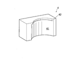
- FIG. 2 is an enlarged perspective view showing the guide portion.
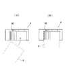
- FIG. 3 is an enlarged view showing the arrangement relationship between the guide portion and the upper portion of the container, wherein (A) shows the position before positioning the container and (B) shows the position after positioning the container.
- 4A and 4B are diagrams showing the container, in which FIG. 4A shows a state before putting ice pieces, and FIG. 4B shows a state after putting ice pieces.
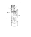
- FIG. 5 is a schematic perspective view showing the arrangement relationship between the raw material liquid nozzle, the carbonic acid liquid nozzle, and the inner wall surface of the container.
- FIG. 6A and 6B are schematic views showing the arrangement relationship between the raw material liquid nozzle, the carbonic acid liquid nozzle, and the inner wall surface of the container.
- FIG. 6A is a front view
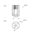
- FIG. FIG. 7 is a view showing an example of a nozzle opening of a raw material liquid nozzle, where (A) is a longitudinal sectional view and (B) is a bottom view.
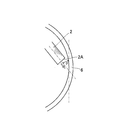
- FIG. 8 is a diagram for explaining the inclination relationship between the discharge direction of the carbonic acid solution nozzle 2 and the inner wall surface of the container.
- FIG. 9 is a diagram illustrating an operation for moving the cartridge reservoir A1 and the carbonic acid solution operating lever 21 to open and close the third valve body provided in the carbonic acid solution dispensing flow path.
- FIG. 10 shows a standby state in which the raw material liquid is filled in the cartridge reservoir, and the first valve body is closed and the raw material liquid cannot be discharged from the raw material nozzle.
- FIG. 11 shows a state where the second valve body is closed and the first valve body is opened, and the raw material liquid is discharged from the raw material nozzle.
- FIG. 12 shows a state where the first valve body is closed and the second valve body is opened, and the raw material liquid is supplied to the empty cartridge reservoir.
- FIG. 13 shows a high carbonated beverage supply apparatus provided with a nozzle for adding a raw material liquid.
- FIG. 14 is a schematic perspective view showing the arrangement relationship with the inner wall surface of the container when the raw material liquid addition nozzle is provided.
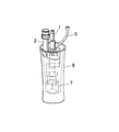
- FIG. 15 is an explanatory diagram of the raw material liquid flow path in the high carbonated beverage supply apparatus A in which the raw material liquid is allowed to flow directly from the raw material liquid tank to the raw material liquid nozzle.
- FIG. 16 is an explanatory diagram of the raw material liquid channel in the embodiment of FIGS.
- the high carbonated beverage supply apparatus A of the present invention performs positioning of a raw material liquid nozzle 1 for pouring a raw material liquid, a carbonic acid liquid nozzle 2 for discharging a carbonic acid liquid, a receiving part 3 for placing a container 6, and a container. And a guide unit 4. After being temporarily placed on the receiving part 3 and then lifted and positioned by the guide part 4, the raw material liquid 1 and the carbonic acid liquid nozzle 2 are used to supply the raw material liquid and carbonic acid, respectively. The liquid can be discharged.
- the raw material liquid is a liquid such as alcohol-containing beverages (for example, whiskey, brandy, shochu, liqueur, etc.), fruit juice, etc.
- the carbonic acid liquid is a liquid for diluting the raw material liquid containing carbon dioxide gas.
- the ice piece 7 (ice block)
- the surface has not been smoothed yet, and the surface with burrs or the like is rough, and various shapes such as a cube, a sphere, and a square are used. Needless to say, an ice piece with a smooth ice surface can also be used.
- the raw material liquid discharged from each nozzle and the carbonic acid liquid are mixed in the container 6 to obtain a high-carbonic beverage liquid.
- FIG. 1 is an overall schematic diagram showing a carbonated beverage server apparatus X equipped with a high carbonated beverage supply apparatus A.
- the carbonated beverage server device X is provided with a high carbonated beverage supply device A on the front surface thereof.
- the high carbonated beverage supply apparatus A includes a raw material liquid nozzle 1 for discharging a raw material liquid and a carbonic acid liquid nozzle 2 for discharging a carbonic acid liquid, and a container 6 is disposed below the nozzles at a predetermined distance.
- a receiving portion 3 to be placed is provided.
- the receiving portion 3 is provided with an eye plate portion 31 having a notch portion for dropping liquid, and the container 6 is temporarily placed on the eye plate portion 31. Moisture adhering to the container 6 and overflowing liquid fall downward from the eye plate part 31 and accumulate in the receiving part 3.
- a guide portion 4 is provided above the receiving portion 3 of the container 6 (below the raw material liquid nozzle 1 and the carbonic acid solution nozzle 2) (see FIG. 1), and when the raw material liquid is discharged, the container 6 is The guide part 4 is positioned at an appropriate position with respect to the raw material liquid nozzle 1 and the carbonic acid liquid nozzle 2.
- FIG. 2 is an enlarged perspective view showing the guide portion 4.
- FIG. 3 is an enlarged view showing the arrangement relationship between the guide part and the upper part of the container.
- FIG. 3A shows a state before positioning the container
- FIG. 3B shows a state after positioning the container.
- the guide portion 4 includes a concave portion 41 that is a portion having a curve corresponding to the shape of the upper side surface of the container 6, and a convex portion 42 that is a portion that covers a part of the upper end portion of the container 6.
- the container 6 temporarily placed on the receiving part 3 is lifted and aligned with the guide part 4 so that the container 6 is positioned at appropriate positions below the raw material liquid nozzle 1 and the carbonic acid liquid nozzle 2 in the vertical and horizontal directions.
- FIG. 4A and 4B are schematic views showing the container 6, in which FIG. 4A shows a state before the ice piece 7 is put, and FIG. 4B shows a state after the ice piece 7 is put.
- FIG. 5 is a schematic perspective view showing an arrangement relationship among the raw material liquid nozzle 1, the carbonic acid liquid nozzle 2, and the inner wall surface of the container 6. In this figure, the guide part is omitted.
- FIG. 6 is a schematic view showing the arrangement relationship between the raw material liquid nozzle 1, the carbonic acid liquid nozzle 2, and the inner wall surface of the container 6.
- FIG. 6A is a front view, and FIG. It shows with.
- the raw material liquid nozzle 1 is connected to a raw material liquid tank (not shown) via a raw material liquid supply flow path, and is disposed so as to be discharged to the center of the positioned container 6.
- the raw material liquid nozzle 1 is provided with the some hole H, and can spray a raw material liquid to the whole ice piece 7 reliably.
- the raw material liquid may be cooled at room temperature (room temperature), or at room temperature, mainly due to the temperature difference between the raw material liquid and ice, and when cooled, due to the reaction heat due to contact between the raw material liquid and ice,
- the ice pieces 7 that have been sprayed with the raw material liquid are not melted with burrs (spine-like splinters) existing on the surface thereof, and the surface becomes uniform and smooth.
- burrs spine-like splinters
- FIG. 7 is a view showing an example of the nozzle opening 1A of the raw material liquid nozzle 1, in which (A) is a longitudinal sectional view, and (B) is a bottom view.
- (A) is a longitudinal sectional view
- (B) is a bottom view.
- eight holes H are provided around the periphery, and a total of nine holes are provided.
- the carbonate solution nozzle 2 is connected to a carbonate solution production tank (not shown), and the carbonate solution cooled from the carbonate solution production tank by moving the carbonate solution operation lever 21 is discharged to the container 6 through the carbonate solution nozzle 2. Supplied.
- the carbonic acid solution nozzle 2 is arranged such that a pipe-like nozzle extends downward and bends along the inner wall surface of the container 6.
- the discharge direction of the carbonic acid solution nozzle 2 (the direction in which the liquid jumps out) is provided so as to incline by a certain angle ⁇ with respect to the horizontal tangential direction of the inner wall surface of the opposing container 6.
- the angle ⁇ refers to an angle formed by the tangential direction at the intersection of the central axis of the carbonic acid solution nozzle 2 and the inner wall surface.
- FIG. 8 is a view for explaining the inclination relationship between the discharge direction of the carbonic acid solution nozzle 2 and the inner wall surface of the container 6.
- the inclination angle ⁇ is less than 90 degrees, but from the viewpoint of suppressing the generation of carbon dioxide bubbles as much as possible, for example, 10 to 70 degrees is preferably employed.
- FIG. 9 is an explanatory diagram of the cartridge reservoir A1 that temporarily stores the raw material liquid, which is provided in the high carbonated beverage supply apparatus A of the present invention.
- the cartridge reservoir A1 is connected to a raw material liquid tank (not shown) via the raw material liquid supply channel 14, and the raw material liquid is additionally supplied from the raw material liquid tank to the cartridge reservoir A1. Further, the cartridge reservoir A1 is connected to the raw material liquid nozzle 1 via the raw material liquid discharge channel 12, and a fixed amount (one shot) of the raw material liquid W is filled in the cartridge reservoir A1. By moving the raw material liquid operation lever 11, the liquid is discharged into the container 6 through the raw material liquid nozzle 1. When the cartridge reservoir A1 becomes empty (colored), the raw material liquid is filled into the cartridge reservoir A1 from the raw material liquid tank through the raw material liquid supply channel 14 by a fixed amount (one shot). It has become.
- FIG. 9 is a diagram for explaining an operation for opening and closing the third valve body 23 provided in the carbonic acid solution dispensing flow path 22 by moving the carbonic acid solution operating lever 21.
- (A) shows a state (standby state) where the third valve body 23 cannot be discharged
- (B) shows a state where the third valve body 23 is opened and can discharge the carbonic acid solution. Note that the structure for transmitting the movement of the carbonic acid solution operating lever 21 to the third valve body 23 is omitted.
- the vertical carbonic acid solution operating lever 21 is moved and leveled, the closed third valve body 23 is opened, and the carbonic acid liquid discharge passage 22 can be passed. Therefore, the carbonic acid solution is discharged from the carbonic acid solution nozzle 2.
- the cartridge reservoir A1 is connected to the raw material liquid tank, and the raw material liquid is filled from the raw material liquid tank through the raw material liquid supply flow path into the cartridge reservoir A1 by a certain amount (one shot).
- One-shot is the amount of raw liquid required for the production of high carbonated beverages for a full container, which is often 30 ml, 45 ml, 60 ml, etc., but is set appropriately depending on the type of raw material liquid and the type of high carbonated beverage you want to make Is done.
- a predetermined amount (one shot) of the raw material liquid is discharged from the cartridge reservoir A1 to the container 6 through the raw material liquid nozzle 1.
- a valve switching safety mechanism is provided between the raw material liquid supply flow path 14 from the raw material liquid tank to the cartridge reservoir A1 and the raw material liquid extraction flow path 12 that guides the raw material liquid filled in the cartridge reservoir A1 and pours it out.
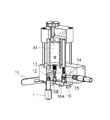
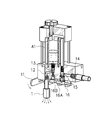
- FIGS. 10 to 12 are internal sectional views of a partial cross section for explaining the valve switching safety mechanism.
- the cover body A1a covering the cartridge reservoir A1 is omitted for convenience.
- FIG. 10 shows a state (standby state) in which the raw material liquid is filled in the cartridge reservoir A1, and the first valve body 13 is closed and the raw material liquid cannot be discharged from the raw material nozzle.
- FIG. 11 shows a state where the second valve body 15 is closed and the first valve body 13 is opened, and the raw material liquid is discharged from the raw material nozzle 1.
- FIG. 12 shows a state where the first valve body 13 is closed and the second valve body 15 is opened, and the raw material liquid is supplied to the empty cartridge reservoir A1.
- a first valve body 13 is provided in the raw material liquid extraction flow path 12 which is a flow path for discharging the raw material liquid filled in the cartridge storage device A1 to the outside.
- a second valve body 15 is provided in the raw material liquid supply flow path 14 which is a flow path for supplying the raw material liquid.
- a cam rod 16 is provided in common for making these passages passable or not passable, that is, for opening and closing each valve body.
- the cam rod 16 slides in the horizontal direction, and opens and closes the first valve body 13 and the second valve body 15. Specifically, the cam rod 16 is in perpendicular contact with the first valve body 13 and the second valve body 15, and the first valve body 13 and the second valve body 15 are opened and closed synchronously by the movement of the cam rod 16. be able to.
- the first valve body 13 is normally biased downward by a spring so that the flow path cannot pass through, but has a structure that opens when the spring is overcome and pushed up.
- the second valve body 15 is normally biased downward by a spring so that the flow path can pass therethrough. However, the second valve body 15 has a structure that closes when the spring is overcome and pushed up.
- the raw material liquid supply flow path 14 can pass, the raw material liquid is supplied again to the emptied cartridge reservoir A1 until a predetermined amount (one shot) is obtained (see FIG. 12).
- the pressure for supplying the raw material liquid depends on the pressure of the flow jet pump, for example.
- the first valve body 13 is closed, the raw material liquid is not discharged from the raw material liquid nozzle 1.
- the first valve body 13 is opened after the second valve body 15 is closed by the forward movement of the cam rod 16, and the first valve body is opened by the reverse movement of the cam rod 16.
- the second valve body 15 opens after 13 is closed.
- the raw material liquid is not supplied to the cartridge reservoir A1, and the raw material liquid for one shot is poured accurately into the container 6.
- the raw material liquid is not inadvertently supplied to the cartridge reservoir A ⁇ b> 1, and this prevents the raw material liquid from being excessively injected into the container 6. Is done.
- the raw material liquid can be poured into the container 6 with peace of mind. Incidentally, in order to change a certain amount (one shot) of the cartridge reservoir A1, it is performed by changing the volume of the internal space, but the details are omitted.
- the raw material liquid is discharged into the container 6 containing the ice pieces 7 while being in contact with the ice pieces 7 (raw material liquid discharge), and then the carbonic acid solution is brought into contact with the inner wall surface of the container 6. Discharge while discharging (carbonic acid solution discharge).
- the key point for producing a highly carbonated beverage, that is, the trick is to discharge the carbonated liquid after discharging the raw material liquid.
- the container 6 Temporarily place the container 6 containing the ice pieces 7 on the receiving part 3.
- the container 6 is properly positioned in the vertical and horizontal directions, the raw material liquid nozzle 1 is positioned above the central part of the container 6, and the carbonic acid liquid nozzle 2 is 6 along the inner wall surface.
- the discharge direction of the carbonic acid solution nozzle 2 is arranged to be inclined by an angle ⁇ with respect to the horizontal tangential direction of the inner wall surface of the container 6 (see FIG. 8).
- the raw material liquid operation lever 11 is operated to discharge the raw material liquid (whiskey or the like) from the raw material liquid nozzle 1.
- the discharged raw material liquid falls on the ice piece 7 in the container 6 and first smoothes the rough surface of the ice piece 7. That is, burrs and the like on the surface of the ice piece 7 are eliminated to make a smooth surface. This eliminates the carbon dioxide escape factor 1 described above. Since the raw material liquid nozzle 1 is located at the center of the container 6, the raw material liquid falls evenly on the entire ice piece 7, and since the raw material liquid nozzle 1 has a plurality of holes, the raw material liquid is iced. The whole piece 7 is sprayed.
- the carbonated liquid operation lever 21 is moved to discharge the carbonated liquid from the carbonated liquid nozzle 2, and the carbonated liquid flows along the inner wall surface of the container 6. Moreover, since the discharge direction of the carbonic acid solution nozzle 2 is inclined by an angle ⁇ with respect to the horizontal tangential direction of the inner wall surface of the container 6, there is no impact and the carbon dioxide gas does not escape. This eliminates the carbon dioxide escape factor 2 described above. Thus, the carbonic acid solution does not collide with the inner wall surface of the container 6 in an impact manner, and does not fall directly on the ice piece 7 as much as possible.
- the present invention has been described above, the present invention is not limited to the embodiments, and various modifications can be made.
- another raw material liquid nozzle for adjusting the concentration so as to meet the taste of a person who drinks a carbonated beverage.
- the amount of the raw material liquid for one shot is regulated, so that it is not possible when a thick carbonated beverage is required according to customer preference.
- Such a case can be dealt with by providing a raw material liquid addition nozzle (connected to the raw material liquid tank) for further adding an additional raw material liquid to thicken the carbonated beverage.
- FIG. 13 shows a supply device A for a high carbonated beverage provided with a nozzle 5 for adding a raw material liquid.
- FIG. 14 is a schematic perspective view showing the arrangement relationship with the inner wall surface of the container 6 when the raw material liquid addition nozzle 5 is provided. Therefore, for a person who prefers a beverage with a high concentration of the raw material liquid, an additional raw material liquid is added to the container 6 by operating the operation lever (not shown) of the raw material liquid adding nozzle 5.
- the addition of the addition raw material liquid from the raw material liquid addition nozzle 5 may be after the above-described raw material liquid discharge or after the carbonic acid liquid discharge.
- the supply apparatus of the high carbonated beverages shown in FIG.13 and FIG.14 is equipped with cartridge storage device A1, and has the function to discharge the raw material liquid for one shot in a container in principle. Therefore, three nozzles of the raw material liquid nozzle 1, the raw material liquid addition nozzle 5, and the carbonic acid liquid nozzle 2 are required. By supplying the raw material liquid directly from the raw material liquid tank T to the raw material liquid nozzle 1 without providing the cartridge reservoir A1, the number of nozzles can be reduced.
- FIG. 15 is an explanatory diagram of the raw material liquid flow path in the high carbonated beverage supply apparatus A in which the raw material liquid is allowed to flow directly from the raw material liquid tank T to the raw material liquid nozzle 1.
- a raw material liquid supply passage 14A is provided between the raw material liquid tank T and the raw material liquid nozzle 1, and a valve body 13A is provided in the raw material liquid supply passage 14A.
- the amount of the raw material liquid discharged to the container can be increased or decreased or freely adjusted by using the valve body 13A as an electromagnetic valve and opening and closing by switching the switch.
- the electromagnetic valve is switched by electric drive, it is naturally possible to set the raw material liquid so as to have a constant discharge amount.
- valve body 13A can be opened and closed by mechanical drive by moving the raw material liquid operation lever.
- the amount of the raw material liquid discharged to the container can be increased or decreased or freely adjusted by operating the raw material liquid operation lever.
- the high carbonated beverage supply device A has been described as an example, but it is naturally also possible to design a plurality of so-called nozzle towers (supports).
- FIG. 1 For reference, an explanatory diagram of the raw material liquid flow path in the embodiment of FIGS. 1 to 12 is shown in FIG.
- the high carbonated beverage supply device of the present invention is provided such that the raw material liquid nozzle is positioned at the center of the container, the nozzle hole of the carbonate liquid nozzle is disposed along the inner wall surface of the container, and the carbonated liquid Is discharged so as to be inclined at an angle ⁇ with respect to the horizontal tangential direction of the inner wall surface, so that the raw material liquid is applied evenly to the entire ice pieces in the container. Further, the carbonic acid solution does not directly collide with the inner wall surface of the container, and the carbon dioxide contained in the carbonated water is difficult to escape. As long as this principle can be used, it can be widely used in a discharge device for a liquid containing gas.
Landscapes
- Devices For Dispensing Beverages (AREA)
- Containers And Packaging Bodies Having A Special Means To Remove Contents (AREA)
Abstract
Description
この炭酸飲料を供給する飲料ディスペンサは、炭酸液と原料液をそれぞれノズルから別々に容器に供給して飲料液とするものである。
このような飲料ディスペンサとして例えば、特許文献1には、ベース飲料(酎ハイ等)と添加シロップを各ノズルから同時にカップに供給する構造の飲料ディスペンサが提供されている。
この飲料ディスペンサでは、ベース飲料用のノズルと添加シロップ用のノズルとは左右に近接して並んで配置される構造となっているため、ベース飲料(酎ハイ等)と添加シロップは同じ方向に吐出される。
その結果、炭酸ガスの溶け込み率の低い、いわゆる炭酸の効きが悪い飲料液となってしまう。
このような問題点を解決するものとして、特許文献2に示すような飲料液供給装置が開発されている。
そして、希釈液ノズルの希釈液吐出口を飲料容器の内壁面に対峙するように配設し、希釈液を内壁面に向けて吐出して流下させるものである。
そのため、炭酸ガスの抜け出しが少なくなり、いわゆる炭酸の効きがよい高炭酸の飲料を調製することができる。
そのため容器の内壁面への衝突時に炭酸液に含まれている炭酸ガスが抜け出してしまう。
本発明は、このような技術的な問題点を解決するものである。
すなわち、本発明は、炭酸液が容器の内壁面に衝突して炭酸液から炭酸ガスが極力抜け出すようなことがない高炭酸飲料の供給装置を提供することを目的とする。
また炭酸液が容器の内壁面に、直接、衝突することはなく、炭酸水に含まれる炭酸ガスが抜け出しにくい。
(高炭酸飲料の供給装置)
本発明の高炭酸飲料の供給装置Aは、原料液を注出する原料液ノズル1と炭酸液を吐出する炭酸液ノズル2と、容器6を載置する受け部3と、容器の位置決めを行うガイド部4とを備えている。
受け部3に一旦仮置きされた後、持ち上げられてガイド部4で位置決めされた状態の氷片7入り容器6に対して、原料液ノズル1と炭酸液ノズル2とから、それぞれ原料液と炭酸液とを吐出することができる。
尤も、氷の表面が滑らになった氷片も使用可能なことはいうまでもない。
本発明では、それぞれのノズルから吐出された原料液と炭酸液とが容器6内で混合されて高炭酸の飲料液となる。
炭酸飲料サーバ装置Xの前面部には高炭酸飲料の供給装置Aが備わっている。
高炭酸飲料の供給装置Aは、原料液を吐出する原料液ノズル1と、炭酸液を吐出する炭酸液ノズル2とを備えており、これら各ノズルから所定の距離離れた下方には容器6を載置する受け部3が設けられている。
この受け部3には、液落とし用の切欠き部がある目皿部31が設けられており、容器6はこの目皿部31の上に仮置きされる。
容器6に付着した水分やあふれた液は目皿部31から下方に落下し受け部3に溜まる。
また、図3は、ガイド部と容器上部との配設関係を拡大して示す図であり、(A)は、容器を位置決めする前、(B)は容器を位置決めした後を示す。
ガイド部4は、容器6の上部側面形状に応じたカーブを持つ部分である凹部41と、容器6の上端部の一部に被さる部分である凸部42を有する。
位置決めは、受け部3に仮置きした容器6を持ち上げてこのガイド部4に合わせることにより、容器6は上下、左右方向ともに原料液ノズル1と炭酸液ノズル2の下方の適正な部位に位置決めされる。
図5は、原料液ノズル1と炭酸液ノズル2と容器6の内壁面との配設関係を示した概略斜視図である。
なお、この図ではガイド部は省略している。
ここで原料液ノズル1は、図示しない原料液タンクに原料液供給流路を介して連結されており、位置決めされた容器6の中央部に吐出するように配置されている。
そして原料液ノズル1は、複数の孔Hを備えており、氷片7の全体に偏りなく確実に原料液を散布することができる。
原料液は常温(室温)でも冷却されたものでもよく、常温の場合は主に原料液と氷との温度差により、また冷却されていた場合は原料液と氷との接触による反応熱により、原料液の散布を受けた氷片7は、その表面に存在するバリ(棘状のトゲトゲ)が溶けてなくなり、表面が均一に且つ滑らかになる。
併せて、原料液の吐出により氷の表面が原料液でコーティングされた状態になるので氷片7の表面が更に滑らかになる。
この例は、中心部の孔Hの他、更に周囲に8個の孔Hを備え、合計9個の孔を有するものである。
炭酸液ノズル2はパイプ状のノズルが下方に伸びて屈曲し容器6の内壁面に沿うような状態で配置される。
そして炭酸液ノズル2の吐出方向(液の飛び出し方向)は、対向する容器6の内壁面の水平接線方向に対して一定角度θだけ傾斜して吐出するように設けられている。
この場合、角度θは、炭酸液ノズル2の中心軸線と内壁面との交差点における接線方向とのなす角度をいう。
このように液の吐出方向を角度θだけ傾斜させたことにより、炭酸液は確実に容器6の内壁面に沿うようにして螺旋状に効率よく流れることとなる。
この場合、傾斜する角度θは、90度未満が採用されるが、炭酸ガスの泡発生を極力抑止する観点から、例えば10~70度が好ましく採用される。
このカートリッジ貯留器A1は、原料液供給流路14を介して図示しない原料液タンクと連結されており、この原料液タンクからカートリッジ貯留器A1に原料液が追加供給される。
また、カートリッジ貯留器A1は原料液注出流路12を介して原料液ノズル1と連結されており、このカートリッジ貯留器A1に、充填されている一定量(ワンショット分)Wの原料液が、原料液操作レバー11を動かすことで、原料液ノズル1を介して容器6に吐出される。
なお、カートリッジ貯留器A1が空(カラ)になった場合は、原料液タンクから原料液供給流路14を通って原料液が一定量(ワンショット分)カートリッジ貯留器A1に充填されるようになっている。
(A)は、第3弁体23が閉じた炭酸液を吐出できない状態(待機状態)を示し、(B)第3弁体23が開いて炭酸液を吐出できる状態を示す。
なお、炭酸液操作レバー21の動きを第3弁体23に伝える構造は省略している。
垂直にある炭酸液操作レバー21を動かし水平にすると、閉じている第3弁体23が開き、炭酸液注出流路22が通過可能となる。
そのため炭酸液ノズル2から炭酸液が吐出される。
ところで前述したように、カートリッジ貯留器A1は原料液タンクに連結されており、原料液タンクから原料液供給流路を通って原料液が一定量(ワンショット分)カートリッジ貯留器A1に充填される。
ワンショットとは、容器一杯分の高炭酸飲料の製造に必要な原料液の量で30ml、45ml、60ml等であることが多いが、原料液の種類や作りたい高炭酸飲料の種類により適宜設定される。
そして、原料液操作レバーを動かすことで、カートリッジ貯留器A1から一定量(ワンショット分)の原料液が原料液ノズル1を介して容器6に吐出される。
この場合、原料液タンクからカートリッジ貯留器A1に至る原料液供給流路14と、カートリッジ貯留器A1に充填された原料液を導いて外部に注出する原料液注出流路12との間に弁切り替え安全機構が設けられている。
なお、カートリッジ貯留器A1を覆うカバー体A1aは便宜的に省略した。
図10は、カートリッジ貯留器A1に原料液が充填された状態であって、第1弁体13が閉じて原料ノズルから原料液が吐出できない状態(待機状態)を示す。
図12は、第1弁体13が閉じ第2弁体15が開いて、空のカートリッジ貯留器A1に原料液が供給される状態を示す。
そしてこの両流路を通過可能又は通過不能とするための、すなわち各弁体を開閉するためのカム棒16が共通に設けられている。
詳しくは、カム棒16が第1弁体13と第2弁体15とに垂直に当接しており、カム棒16の動きによって第1弁体13と第2弁体15を同期的に開閉することができる。
第1弁体13は、通常、バネで下方に付勢されて流路が通過不能となっているが、バネに打ち勝って押し上げられると開く構造である。
また第2弁体15は、通常、バネで下方に付勢されて流路が通過可能となっているが、バネに打ち勝って押し上げられると閉じる構造である。
A)最初、第1弁体13は閉じて第2弁体15は開いており、カートリッジ貯留器A1に一定量(ワンショット分)の原料液が充填されている(図10参照)。
いわゆる待機状態である。
同時に、太径部16Aで第2弁体15を押し上げ第2弁体15が閉じる(すなわち原料液供給流路14が通過不能となる)。
この場合、原料液ノズル1から図示しない外部の容器6に原料液が吐出されるが(図11参照)、第2弁体15が閉じているので原料液供給流路14を介してカートリッジ貯留器A1に原料液は充填されない。
同時に、細径部16Bにより第2弁体15を押し下げ第2弁体15が開く。
なお、原料液を供給する圧は例えばフロージェットポンプの圧による。
この場合、第1弁体13が閉じているので原料液ノズル1から原料液は吐出されない。
A)~C)から分かるように、カム棒16の順方向の動きによって第2弁体15が閉じてから第1弁体13が開き、またカム棒16の逆方向の動きによって第1弁体13が閉じてから第2弁体15が開く。
原料液を容器6に注いでいる途中で、不用意にカートリッジ貯留器A1に原料液が供給されるようなことがなく、それが原因で容器6へ原料液が余分に注入されることが防止される。
このような弁切り替え安全機構により安心して容器6に原料液を注ぐことができる。
因みに、カートリッジ貯留器A1の一定量(ワンショット分)を変えるには、その内部空間の体積を変更することによって行うが詳細は省略する。
ところで炭酸液から炭酸ガスが抜け出る原因は、二つあり、その一つは炭酸液が粗い表面を有する氷片7に接触することで溶け込んでいる炭酸ガスが抜け出すから(炭酸ガス抜け出し要因1)であり、他の一つは、炭酸液が容器6の内壁面に直接衝突しその衝撃によって溶け込んでいる炭酸ガスが抜け出すから(炭酸ガス抜け出し要因2)である。
炭酸液吐出は、必ず、原料液吐出の後に行うことが高炭酸飲料を製造するキーポイント、すなわちコツである。
ついで、容器6を持ち上げて、ガイド部4に合わせると、容器6の上下、左右方向とも適正に位置決めされ、原料液ノズル1が容器6の中央部上方に位置し、且つ炭酸液ノズル2は容器6の内壁面に沿うように配置される。(図3、図5参照)
詳しくは前述したように炭酸液ノズル2の吐出方向が容器6の内壁面の水平接線方向に対して角度θだけ傾斜して配置される(図8参照)。
吐出された原料液は、容器6内の氷片7に降りかかり、まず氷片7の粗い表面を滑らかにする。
すなわち、氷片7の表面のバリ等を消失させて滑らかな面にする。
これで上述した炭酸ガス抜け出し要因1が解消される。
原料液ノズル1は、容器6の中央部に位置しているので、原料液は氷片7全体に偏りなく降りかかり、また原料液ノズル1が複数の孔を備えていることにより、原料液は氷片7全体に散布される。
しかも炭酸液ノズル2の吐出方向を容器6の内壁面の水平接線方向に対して角度θだけ傾斜させた状態とするので、衝撃がなく炭酸ガスが抜け出すことはない。
これで上述した炭酸ガス抜け出し要因2が解消される。
このように炭酸液は容器6の内壁面に衝撃的に衝突しないだけでなく、氷片7にも、直接には極力降りかからない。
因みに容器6の底部で溜まった炭酸液が氷片7に接触しても、既に原料液によって氷片7の表面が均一に円滑化されているので炭酸液から炭酸ガスが抜け出さない。
以上で氷片7の入った容器6に原料液と炭酸液を供給する手順が完了する。
例えば、炭酸飲料を飲む者の好みに対応できるように、濃さを調整のための別の原料液ノズルを設けることも可能である。
本来、ワンショット分の原料液は、その量が規定されているので、お客の好みにより濃い炭酸飲料が求められる場合には対応できない。
このような場合は、炭酸飲料を濃くするため更に加算用原料液を追加する原料液追加用ノズル(原料液タンクに連結されている)を設けることで対応する。
図14は、原料液追加用ノズル5を設けた場合における容器6の内壁面との配設関係を示した概略斜視図である。
従って、原料液の濃い飲料液を好む者に対しては、この原料液追加用ノズル5の操作レバー(図示しない)を操作して加算用原料液を容器6に余分に追加する。
原料液追加用ノズル5からの加算用原料液の追加は、上述した原料液吐出の後でもよいし、また炭酸液吐出の後でもよい。
そのため原料液ノズル1と原料液追加用ノズル5と炭酸液ノズル2の3つのノズルが必要となる。
カートリッジ貯留器A1を備えず、直接、原料液タンクTから原料液ノズル1に原料液を流すようにすることで、ノズルの数を少なくすることができる。
ここでは、原料液タンクTと原料液ノズル1との間に、原料液供給流路14Aを設け、該原料液供給流路14Aに弁体13Aを設ける。
この場合、弁体13Aを電磁弁にしてスイッチの切り替えにより開閉可能とすることにより、容器に吐出する原料液の量を多くしたり、或いは少なくしたり、自由に調整することができる。
電気的駆動により電磁弁を切り替えをする場合、原料液を一定量の吐出量になるように設定することも当然可能である。
また原料液操作レバーを動かして機械的駆動により弁体13Aを開閉できるようにすることも当然、設計変更可能である。
この場合は、原料液操作レバーの操作により、容器に吐出する原料液の量を多くしたり、或いは少なくしたり、自由に調整することができる。
また炭酸液が容器の内壁面に、直接、衝突することはなく、炭酸水に含まれる炭酸ガスが抜け出しにくい。
この原理を利用できる限り、ガスを含む液の吐出装置等にも広く利用が可能である。
1A・・・ノズル口部
11・・・原料液操作レバー
12・・・原料液注出流路
13・・・第1弁体
13A・・・弁体
14・・・原料液供給流路
14A・・・原料液供給流路
15・・・第2弁体
16・・・カム棒
16A・・・太径部
16B・・・細径部
2・・・炭酸液ノズル
2A・・・開口面
21・・・炭酸液操作レバー
22・・・炭酸液注出流路
23・・・第3弁体
3・・・受け部
31・・・目皿部
4・・・ガイド部
41・・・凹部
42・・・凸部
5・・・原料液追加用ノズル
6・・・容器
7・・・氷片
A・・・高炭酸飲料の供給装置
A1・・・カートリッジ貯留器
A1a・・・カバー体
H・・・孔
T・・・原料液タンク
X・・・炭酸飲料サーバ装置
Claims (9)
- 原料液を注出する原料液ノズルと炭酸液を注出する炭酸液ノズルと、容器を載置する受け部とを備え、ガイド部によって位置決めされた容器に原料液ノズルと炭酸液ノズルとからそれぞれ原料液と炭酸液とを吐出できる高炭酸飲料の供給装置であって、原料液ノズルが容器の中央部に位置するように設けられており、炭酸液ノズルのノズル孔は、容器の内壁面に沿って配置され、且つ炭酸液の吐出方向が内壁面の水平接線方向に対して角度θだけ傾斜して吐出するように設けられていることを特徴とする高炭酸飲料の供給装置。
- 原料液ノズルが原料液を多方向に吐出する複数の孔を備えるものであることを特徴とする請求項1記載の高炭酸飲料の供給装置。
- 角度θが10度~70度であることを特徴とする請求項1又は2記載の高炭酸飲料の供給装置。
- ガイド部は、容器の上部側面形状に応じたカーブを持つ凹部と、容器の上端部の一部に被さる凸部を有することを特徴とする請求項1ないし3のいずれか一項に記載の高炭酸飲料の供給装置。
- 原料液を一時的に一定量だけ貯蔵するカートリッジ貯留器を備え、該カートリッジ貯留器は原料液供給流路を介して原料液タンクに連結されており、且つ該カートリッジ貯留器は原料液注出流路を介して原料液ノズルに連結されており、カートリッジ貯留器の原料液を一定量だけ原料液ノズルから吐出するものであることを特徴とする請求項1記載の高炭酸飲料の供給装置。
- 原料液供給流路に第1弁体が設けられ、且つ原料液注出流路には第2弁体が設けられ、両弁体を開閉操作するための共通のカム棒が設けられていることを特徴とする請求項5記載の高炭酸飲料の供給装置。
- カム棒は第1弁体と第2弁体とに垂直に当接しており、カム棒の動きによって第1弁体と第2弁体とを開閉することを特徴とする請求項6記載の高炭酸飲料の供給装置。
- カム棒の順方向の動きによって第2弁体が閉じてから第1弁体が開き、またカム棒の逆方向の動きによって第5弁体が閉じてから第2弁体が開くものであることを特徴とする請求項7記載の高炭酸飲料の供給装置。
- 加算用原料液を追加するための原料液追加用ノズルを更に設けたことを特徴とする請求項1記載の高炭酸飲料の供給装置。
Priority Applications (3)
| Application Number | Priority Date | Filing Date | Title |
|---|---|---|---|
| KR1020167036272A KR102363517B1 (ko) | 2014-07-23 | 2015-06-19 | 고탄산 음료의 공급 장치 |
| CN201580038108.2A CN106660772B (zh) | 2014-07-23 | 2015-06-19 | 高碳酸饮料的供给装置 |
| JP2016535765A JP6595994B2 (ja) | 2014-07-23 | 2015-06-19 | 高炭酸飲料の供給装置 |
Applications Claiming Priority (2)
| Application Number | Priority Date | Filing Date | Title |
|---|---|---|---|
| JP2014150250 | 2014-07-23 | ||
| JP2014-150250 | 2014-07-23 |
Publications (1)
| Publication Number | Publication Date |
|---|---|
| WO2016013151A1 true WO2016013151A1 (ja) | 2016-01-28 |
Family
ID=55162700
Family Applications (1)
| Application Number | Title | Priority Date | Filing Date |
|---|---|---|---|
| PCT/JP2015/003094 Ceased WO2016013151A1 (ja) | 2014-07-23 | 2015-06-19 | 高炭酸飲料の供給装置 |
Country Status (4)
| Country | Link |
|---|---|
| JP (1) | JP6595994B2 (ja) |
| KR (1) | KR102363517B1 (ja) |
| CN (1) | CN106660772B (ja) |
| WO (1) | WO2016013151A1 (ja) |
Families Citing this family (3)
| Publication number | Priority date | Publication date | Assignee | Title |
|---|---|---|---|---|
| CN111700502A (zh) * | 2019-03-18 | 2020-09-25 | 富士电机株式会社 | 饮料供给装置 |
| KR102222670B1 (ko) | 2020-07-23 | 2021-03-04 | 김태헌 | 하이볼 제조 및 디스펜싱 시스템 |
| KR102838002B1 (ko) * | 2024-10-29 | 2025-07-24 | (주)위벨롭먼트 | 저온 숙성 살얼음 맥주 공급 장치 |
Citations (7)
| Publication number | Priority date | Publication date | Assignee | Title |
|---|---|---|---|---|
| JPH02108900U (ja) * | 1989-02-13 | 1990-08-29 | ||
| JP2000025899A (ja) * | 1998-07-10 | 2000-01-25 | Fuji Electric Co Ltd | 飲料ディスペンサの飲料供給ノズル |
| JP2003137396A (ja) * | 2001-11-07 | 2003-05-14 | Sanyo Electric Co Ltd | 飲料供給装置 |
| JP2003160196A (ja) * | 2001-11-22 | 2003-06-03 | Sanyo Electric Co Ltd | 飲料供給装置 |
| WO2003045832A1 (en) * | 2001-11-30 | 2003-06-05 | Labatt Brewing Company Limited | Beverage dispensing system and device |
| JP3179224U (ja) * | 2012-08-09 | 2012-10-18 | 富士電機リテイルシステムズ株式会社 | 飲料供給装置 |
| US20130255825A1 (en) * | 2012-04-03 | 2013-10-03 | David J. Fedewa | Foam reducing container |
Family Cites Families (10)
| Publication number | Priority date | Publication date | Assignee | Title |
|---|---|---|---|---|
| JPS56145781U (ja) * | 1980-03-26 | 1981-11-04 | ||
| JPH0330320Y2 (ja) * | 1986-02-20 | 1991-06-26 | ||
| JP3939011B2 (ja) * | 1998-03-30 | 2007-06-27 | 三洋電機株式会社 | 飲料供給装置 |
| JP2001106299A (ja) * | 1999-10-06 | 2001-04-17 | Sanden Corp | 炭酸飲料供給装置 |
| JP2001171796A (ja) | 1999-12-14 | 2001-06-26 | Fuji Electric Co Ltd | 飲料ディスペンサ |
| DK1611944T3 (da) * | 2003-03-28 | 2009-11-16 | Suntory Holdings Ltd | Opbevaringsudstyr med en afgangsmekanisme til fast stof |
| JP2007045496A (ja) * | 2005-08-12 | 2007-02-22 | Fuji Electric Retail Systems Co Ltd | 飲料供給装置 |
| JP5617351B2 (ja) * | 2010-05-28 | 2014-11-05 | 富士電機株式会社 | 飲料供給装置 |
| JP5659719B2 (ja) * | 2010-11-12 | 2015-01-28 | 大日本印刷株式会社 | 液化ガス添加用ノズル |
| US8485503B2 (en) * | 2011-04-14 | 2013-07-16 | Skip A. Lei | Multi stream wine aerating device |
-
2015
- 2015-06-19 CN CN201580038108.2A patent/CN106660772B/zh active Active
- 2015-06-19 KR KR1020167036272A patent/KR102363517B1/ko active Active
- 2015-06-19 JP JP2016535765A patent/JP6595994B2/ja active Active
- 2015-06-19 WO PCT/JP2015/003094 patent/WO2016013151A1/ja not_active Ceased
Patent Citations (7)
| Publication number | Priority date | Publication date | Assignee | Title |
|---|---|---|---|---|
| JPH02108900U (ja) * | 1989-02-13 | 1990-08-29 | ||
| JP2000025899A (ja) * | 1998-07-10 | 2000-01-25 | Fuji Electric Co Ltd | 飲料ディスペンサの飲料供給ノズル |
| JP2003137396A (ja) * | 2001-11-07 | 2003-05-14 | Sanyo Electric Co Ltd | 飲料供給装置 |
| JP2003160196A (ja) * | 2001-11-22 | 2003-06-03 | Sanyo Electric Co Ltd | 飲料供給装置 |
| WO2003045832A1 (en) * | 2001-11-30 | 2003-06-05 | Labatt Brewing Company Limited | Beverage dispensing system and device |
| US20130255825A1 (en) * | 2012-04-03 | 2013-10-03 | David J. Fedewa | Foam reducing container |
| JP3179224U (ja) * | 2012-08-09 | 2012-10-18 | 富士電機リテイルシステムズ株式会社 | 飲料供給装置 |
Also Published As
| Publication number | Publication date |
|---|---|
| JPWO2016013151A1 (ja) | 2017-04-27 |
| KR20170038766A (ko) | 2017-04-07 |
| JP6595994B2 (ja) | 2019-10-23 |
| CN106660772A (zh) | 2017-05-10 |
| KR102363517B1 (ko) | 2022-02-16 |
| CN106660772B (zh) | 2019-05-14 |
Similar Documents
| Publication | Publication Date | Title |
|---|---|---|
| TWI619653B (zh) | 噴流裝置 | |
| JP3179224U (ja) | 飲料供給装置 | |
| US5186363A (en) | Liquid mixing and dispensing nozzle | |
| JP6595994B2 (ja) | 高炭酸飲料の供給装置 | |
| KR20150113173A (ko) | 카란, 서버, 주출 부재 및 탈착 공구 | |
| JP6595995B2 (ja) | 高炭酸飲料の供給方法 | |
| US20160220970A1 (en) | Method and Apparatus for Rapid Carbonation of a Fluid | |
| JP4859757B2 (ja) | 発泡性飲料サーバー | |
| JP6713228B2 (ja) | 液体注出装置 | |
| JP5672777B2 (ja) | 飲料供給装置の飲料ノズル | |
| JP7307626B2 (ja) | 飲料自動注出装置 | |
| JP6511335B2 (ja) | 発泡性飲料自動注出装置 | |
| JP6088416B2 (ja) | 飲料の製造方法、及び飲料 | |
| JP2016078858A (ja) | 泡コック | |
| JP2016059372A (ja) | 容器入りコーヒー飲料、容器入りコーヒー飲料の製造方法、コーヒー用ディスペンサーおよびコーヒーサーバー装置 | |
| JP7321831B2 (ja) | 炭酸飲料用注出ノズル | |
| JP7633050B2 (ja) | 飲料サーバー | |
| TWI748658B (zh) | 飲料機及注出構件 | |
| JP2006016048A (ja) | 飲料注出バルブ | |
| WO2020138099A1 (ja) | 発泡性飲料の注出装置 | |
| WO2026053868A1 (ja) | 炭酸水製造装置及びそれを用いた炭酸水の製造方法 | |
| CN105520642B (zh) | 饮料供应装置的多路阀 | |
| JP2017197254A (ja) | 飲料充填装置 | |
| KR20170085350A (ko) | 생맥주 인출밸브 | |
| JP6094860B2 (ja) | ピッチャー |
Legal Events
| Date | Code | Title | Description |
|---|---|---|---|
| 121 | Ep: the epo has been informed by wipo that ep was designated in this application |
Ref document number: 15825426 Country of ref document: EP Kind code of ref document: A1 |
|
| ENP | Entry into the national phase |
Ref document number: 20167036272 Country of ref document: KR Kind code of ref document: A |
|
| ENP | Entry into the national phase |
Ref document number: 2016535765 Country of ref document: JP Kind code of ref document: A |
|
| NENP | Non-entry into the national phase |
Ref country code: DE |
|
| 122 | Ep: pct application non-entry in european phase |
Ref document number: 15825426 Country of ref document: EP Kind code of ref document: A1 |