WO2015198717A1 - エアバッグ装置 - Google Patents
エアバッグ装置 Download PDFInfo
- Publication number
- WO2015198717A1 WO2015198717A1 PCT/JP2015/063150 JP2015063150W WO2015198717A1 WO 2015198717 A1 WO2015198717 A1 WO 2015198717A1 JP 2015063150 W JP2015063150 W JP 2015063150W WO 2015198717 A1 WO2015198717 A1 WO 2015198717A1
- Authority
- WO
- WIPO (PCT)
- Prior art keywords
- airbag
- collision
- tether
- vehicle
- deployed
- Prior art date
- Legal status (The legal status is an assumption and is not a legal conclusion. Google has not performed a legal analysis and makes no representation as to the accuracy of the status listed.)
- Ceased
Links
Images






Classifications
-
- B—PERFORMING OPERATIONS; TRANSPORTING
- B60—VEHICLES IN GENERAL
- B60R—VEHICLES, VEHICLE FITTINGS, OR VEHICLE PARTS, NOT OTHERWISE PROVIDED FOR
- B60R21/00—Arrangements or fittings on vehicles for protecting or preventing injuries to occupants or pedestrians in case of accidents or other traffic risks
- B60R21/02—Occupant safety arrangements or fittings, e.g. crash pads
- B60R21/16—Inflatable occupant restraints or confinements designed to inflate upon impact or impending impact, e.g. air bags
- B60R21/23—Inflatable members
- B60R21/231—Inflatable members characterised by their shape, construction or spatial configuration
- B60R21/233—Inflatable members characterised by their shape, construction or spatial configuration comprising a plurality of individual compartments; comprising two or more bag-like members, one within the other
-
- B—PERFORMING OPERATIONS; TRANSPORTING
- B60—VEHICLES IN GENERAL
- B60R—VEHICLES, VEHICLE FITTINGS, OR VEHICLE PARTS, NOT OTHERWISE PROVIDED FOR
- B60R21/00—Arrangements or fittings on vehicles for protecting or preventing injuries to occupants or pedestrians in case of accidents or other traffic risks
- B60R21/01—Electrical circuits for triggering passive safety arrangements, e.g. airbags, safety belt tighteners, in case of vehicle accidents or impending vehicle accidents
- B60R21/013—Electrical circuits for triggering passive safety arrangements, e.g. airbags, safety belt tighteners, in case of vehicle accidents or impending vehicle accidents including means for detecting collisions, impending collisions or roll-over
-
- B—PERFORMING OPERATIONS; TRANSPORTING
- B60—VEHICLES IN GENERAL
- B60R—VEHICLES, VEHICLE FITTINGS, OR VEHICLE PARTS, NOT OTHERWISE PROVIDED FOR
- B60R21/00—Arrangements or fittings on vehicles for protecting or preventing injuries to occupants or pedestrians in case of accidents or other traffic risks
- B60R21/02—Occupant safety arrangements or fittings, e.g. crash pads
- B60R21/16—Inflatable occupant restraints or confinements designed to inflate upon impact or impending impact, e.g. air bags
- B60R21/20—Arrangements for storing inflatable members in their non-use or deflated condition; Arrangement or mounting of air bag modules or components
- B60R21/203—Arrangements for storing inflatable members in their non-use or deflated condition; Arrangement or mounting of air bag modules or components in steering wheels or steering columns
-
- B—PERFORMING OPERATIONS; TRANSPORTING
- B60—VEHICLES IN GENERAL
- B60R—VEHICLES, VEHICLE FITTINGS, OR VEHICLE PARTS, NOT OTHERWISE PROVIDED FOR
- B60R21/00—Arrangements or fittings on vehicles for protecting or preventing injuries to occupants or pedestrians in case of accidents or other traffic risks
- B60R21/02—Occupant safety arrangements or fittings, e.g. crash pads
- B60R21/16—Inflatable occupant restraints or confinements designed to inflate upon impact or impending impact, e.g. air bags
- B60R21/20—Arrangements for storing inflatable members in their non-use or deflated condition; Arrangement or mounting of air bag modules or components
- B60R21/205—Arrangements for storing inflatable members in their non-use or deflated condition; Arrangement or mounting of air bag modules or components in dashboards
-
- B—PERFORMING OPERATIONS; TRANSPORTING
- B60—VEHICLES IN GENERAL
- B60R—VEHICLES, VEHICLE FITTINGS, OR VEHICLE PARTS, NOT OTHERWISE PROVIDED FOR
- B60R21/00—Arrangements or fittings on vehicles for protecting or preventing injuries to occupants or pedestrians in case of accidents or other traffic risks
- B60R21/02—Occupant safety arrangements or fittings, e.g. crash pads
- B60R21/16—Inflatable occupant restraints or confinements designed to inflate upon impact or impending impact, e.g. air bags
- B60R21/23—Inflatable members
- B60R21/231—Inflatable members characterised by their shape, construction or spatial configuration
-
- B—PERFORMING OPERATIONS; TRANSPORTING
- B60—VEHICLES IN GENERAL
- B60R—VEHICLES, VEHICLE FITTINGS, OR VEHICLE PARTS, NOT OTHERWISE PROVIDED FOR
- B60R21/00—Arrangements or fittings on vehicles for protecting or preventing injuries to occupants or pedestrians in case of accidents or other traffic risks
- B60R21/02—Occupant safety arrangements or fittings, e.g. crash pads
- B60R21/16—Inflatable occupant restraints or confinements designed to inflate upon impact or impending impact, e.g. air bags
- B60R21/23—Inflatable members
- B60R21/231—Inflatable members characterised by their shape, construction or spatial configuration
- B60R21/23138—Inflatable members characterised by their shape, construction or spatial configuration specially adapted for side protection
-
- B—PERFORMING OPERATIONS; TRANSPORTING
- B60—VEHICLES IN GENERAL
- B60R—VEHICLES, VEHICLE FITTINGS, OR VEHICLE PARTS, NOT OTHERWISE PROVIDED FOR
- B60R21/00—Arrangements or fittings on vehicles for protecting or preventing injuries to occupants or pedestrians in case of accidents or other traffic risks
- B60R21/02—Occupant safety arrangements or fittings, e.g. crash pads
- B60R21/16—Inflatable occupant restraints or confinements designed to inflate upon impact or impending impact, e.g. air bags
- B60R21/23—Inflatable members
- B60R21/231—Inflatable members characterised by their shape, construction or spatial configuration
- B60R21/2334—Expansion control features
- B60R21/2338—Tethers
-
- B—PERFORMING OPERATIONS; TRANSPORTING
- B60—VEHICLES IN GENERAL
- B60R—VEHICLES, VEHICLE FITTINGS, OR VEHICLE PARTS, NOT OTHERWISE PROVIDED FOR
- B60R21/00—Arrangements or fittings on vehicles for protecting or preventing injuries to occupants or pedestrians in case of accidents or other traffic risks
- B60R21/02—Occupant safety arrangements or fittings, e.g. crash pads
- B60R21/16—Inflatable occupant restraints or confinements designed to inflate upon impact or impending impact, e.g. air bags
- B60R21/23—Inflatable members
- B60R21/239—Inflatable members characterised by their venting means
-
- B—PERFORMING OPERATIONS; TRANSPORTING
- B60—VEHICLES IN GENERAL
- B60R—VEHICLES, VEHICLE FITTINGS, OR VEHICLE PARTS, NOT OTHERWISE PROVIDED FOR
- B60R21/00—Arrangements or fittings on vehicles for protecting or preventing injuries to occupants or pedestrians in case of accidents or other traffic risks
- B60R21/02—Occupant safety arrangements or fittings, e.g. crash pads
- B60R21/16—Inflatable occupant restraints or confinements designed to inflate upon impact or impending impact, e.g. air bags
- B60R21/26—Inflatable occupant restraints or confinements designed to inflate upon impact or impending impact, e.g. air bags characterised by the inflation fluid source or means to control inflation fluid flow
- B60R21/263—Inflatable occupant restraints or confinements designed to inflate upon impact or impending impact, e.g. air bags characterised by the inflation fluid source or means to control inflation fluid flow using a variable source, e.g. plural stage or controlled output
-
- B—PERFORMING OPERATIONS; TRANSPORTING
- B60—VEHICLES IN GENERAL
- B60R—VEHICLES, VEHICLE FITTINGS, OR VEHICLE PARTS, NOT OTHERWISE PROVIDED FOR
- B60R21/00—Arrangements or fittings on vehicles for protecting or preventing injuries to occupants or pedestrians in case of accidents or other traffic risks
- B60R2021/0002—Type of accident
- B60R2021/0004—Frontal collision
-
- B—PERFORMING OPERATIONS; TRANSPORTING
- B60—VEHICLES IN GENERAL
- B60R—VEHICLES, VEHICLE FITTINGS, OR VEHICLE PARTS, NOT OTHERWISE PROVIDED FOR
- B60R21/00—Arrangements or fittings on vehicles for protecting or preventing injuries to occupants or pedestrians in case of accidents or other traffic risks
- B60R2021/0002—Type of accident
- B60R2021/0009—Oblique collision
-
- B—PERFORMING OPERATIONS; TRANSPORTING
- B60—VEHICLES IN GENERAL
- B60R—VEHICLES, VEHICLE FITTINGS, OR VEHICLE PARTS, NOT OTHERWISE PROVIDED FOR
- B60R21/00—Arrangements or fittings on vehicles for protecting or preventing injuries to occupants or pedestrians in case of accidents or other traffic risks
- B60R2021/0002—Type of accident
- B60R2021/0023—Offset collision
-
- B—PERFORMING OPERATIONS; TRANSPORTING
- B60—VEHICLES IN GENERAL
- B60R—VEHICLES, VEHICLE FITTINGS, OR VEHICLE PARTS, NOT OTHERWISE PROVIDED FOR
- B60R21/00—Arrangements or fittings on vehicles for protecting or preventing injuries to occupants or pedestrians in case of accidents or other traffic risks
- B60R2021/003—Arrangements or fittings on vehicles for protecting or preventing injuries to occupants or pedestrians in case of accidents or other traffic risks characterised by occupant or pedestian
- B60R2021/0039—Body parts of the occupant or pedestrian affected by the accident
- B60R2021/0048—Head
-
- B—PERFORMING OPERATIONS; TRANSPORTING
- B60—VEHICLES IN GENERAL
- B60R—VEHICLES, VEHICLE FITTINGS, OR VEHICLE PARTS, NOT OTHERWISE PROVIDED FOR
- B60R21/00—Arrangements or fittings on vehicles for protecting or preventing injuries to occupants or pedestrians in case of accidents or other traffic risks
- B60R21/02—Occupant safety arrangements or fittings, e.g. crash pads
- B60R21/16—Inflatable occupant restraints or confinements designed to inflate upon impact or impending impact, e.g. air bags
- B60R21/23—Inflatable members
- B60R21/231—Inflatable members characterised by their shape, construction or spatial configuration
- B60R2021/23107—Inflatable members characterised by their shape, construction or spatial configuration the bag being integrated in a multi-bag system
-
- B—PERFORMING OPERATIONS; TRANSPORTING
- B60—VEHICLES IN GENERAL
- B60R—VEHICLES, VEHICLE FITTINGS, OR VEHICLE PARTS, NOT OTHERWISE PROVIDED FOR
- B60R21/00—Arrangements or fittings on vehicles for protecting or preventing injuries to occupants or pedestrians in case of accidents or other traffic risks
- B60R21/02—Occupant safety arrangements or fittings, e.g. crash pads
- B60R21/16—Inflatable occupant restraints or confinements designed to inflate upon impact or impending impact, e.g. air bags
- B60R21/23—Inflatable members
- B60R21/231—Inflatable members characterised by their shape, construction or spatial configuration
- B60R21/233—Inflatable members characterised by their shape, construction or spatial configuration comprising a plurality of individual compartments; comprising two or more bag-like members, one within the other
- B60R2021/23308—Inflatable members characterised by their shape, construction or spatial configuration comprising a plurality of individual compartments; comprising two or more bag-like members, one within the other the individual compartments defining the external shape of the bag
-
- B—PERFORMING OPERATIONS; TRANSPORTING
- B60—VEHICLES IN GENERAL
- B60R—VEHICLES, VEHICLE FITTINGS, OR VEHICLE PARTS, NOT OTHERWISE PROVIDED FOR
- B60R21/00—Arrangements or fittings on vehicles for protecting or preventing injuries to occupants or pedestrians in case of accidents or other traffic risks
- B60R21/02—Occupant safety arrangements or fittings, e.g. crash pads
- B60R21/16—Inflatable occupant restraints or confinements designed to inflate upon impact or impending impact, e.g. air bags
- B60R21/23—Inflatable members
- B60R21/231—Inflatable members characterised by their shape, construction or spatial configuration
- B60R21/233—Inflatable members characterised by their shape, construction or spatial configuration comprising a plurality of individual compartments; comprising two or more bag-like members, one within the other
- B60R2021/23324—Inner walls crating separate compartments, e.g. communicating with vents
-
- B—PERFORMING OPERATIONS; TRANSPORTING
- B60—VEHICLES IN GENERAL
- B60R—VEHICLES, VEHICLE FITTINGS, OR VEHICLE PARTS, NOT OTHERWISE PROVIDED FOR
- B60R21/00—Arrangements or fittings on vehicles for protecting or preventing injuries to occupants or pedestrians in case of accidents or other traffic risks
- B60R21/02—Occupant safety arrangements or fittings, e.g. crash pads
- B60R21/16—Inflatable occupant restraints or confinements designed to inflate upon impact or impending impact, e.g. air bags
- B60R21/23—Inflatable members
- B60R21/231—Inflatable members characterised by their shape, construction or spatial configuration
- B60R21/2334—Expansion control features
- B60R21/2338—Tethers
- B60R2021/23382—Internal tether means
-
- B—PERFORMING OPERATIONS; TRANSPORTING
- B60—VEHICLES IN GENERAL
- B60R—VEHICLES, VEHICLE FITTINGS, OR VEHICLE PARTS, NOT OTHERWISE PROVIDED FOR
- B60R21/00—Arrangements or fittings on vehicles for protecting or preventing injuries to occupants or pedestrians in case of accidents or other traffic risks
- B60R21/02—Occupant safety arrangements or fittings, e.g. crash pads
- B60R21/16—Inflatable occupant restraints or confinements designed to inflate upon impact or impending impact, e.g. air bags
- B60R21/23—Inflatable members
- B60R21/231—Inflatable members characterised by their shape, construction or spatial configuration
- B60R21/2334—Expansion control features
- B60R21/2338—Tethers
- B60R2021/23382—Internal tether means
- B60R2021/23384—Internal tether means having ends which are movable or detachable during deployment
-
- B—PERFORMING OPERATIONS; TRANSPORTING
- B60—VEHICLES IN GENERAL
- B60R—VEHICLES, VEHICLE FITTINGS, OR VEHICLE PARTS, NOT OTHERWISE PROVIDED FOR
- B60R21/00—Arrangements or fittings on vehicles for protecting or preventing injuries to occupants or pedestrians in case of accidents or other traffic risks
- B60R21/02—Occupant safety arrangements or fittings, e.g. crash pads
- B60R21/16—Inflatable occupant restraints or confinements designed to inflate upon impact or impending impact, e.g. air bags
- B60R21/23—Inflatable members
- B60R21/231—Inflatable members characterised by their shape, construction or spatial configuration
- B60R21/2334—Expansion control features
- B60R21/2338—Tethers
- B60R2021/23386—External tether means
-
- B—PERFORMING OPERATIONS; TRANSPORTING
- B60—VEHICLES IN GENERAL
- B60R—VEHICLES, VEHICLE FITTINGS, OR VEHICLE PARTS, NOT OTHERWISE PROVIDED FOR
- B60R21/00—Arrangements or fittings on vehicles for protecting or preventing injuries to occupants or pedestrians in case of accidents or other traffic risks
- B60R21/02—Occupant safety arrangements or fittings, e.g. crash pads
- B60R21/16—Inflatable occupant restraints or confinements designed to inflate upon impact or impending impact, e.g. air bags
- B60R21/23—Inflatable members
- B60R21/239—Inflatable members characterised by their venting means
- B60R2021/2395—Inflatable members characterised by their venting means comprising means to control the venting
Definitions
- the present invention relates to an airbag device that protects an occupant in a vehicle by deploying the airbag.
- the present invention relates to an airbag device that is disposed inside an instrument panel (instrument panel) of a vehicle and mainly protects passengers in a passenger seat.
- a passenger airbag device employs a structure in which an inflator that generates inflation gas and an airbag that is inflated and deployed by the gas are accommodated inside the instrument panel.
- the inflator is actuated to inflate the airbag and deploy toward the inside of the vehicle to restrain the passenger from moving forward.
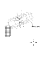
- FIG. 1 is a plan view showing a structure of a conventional vehicle (left-hand drive specification) equipped with an airbag device in a driver seat and a passenger seat, and is 0 with respect to an object (obstacle) at a position shifted from the front. Shows approach at an angle of °.
- a driver's seat airbag 16 is accommodated in the steering wheel 14 in front of the driver 10 and is deployed toward the occupant when a collision occurs.
- an airbag 18 for the passenger seat is accommodated inside the instrument panel (24), and is deployed toward the passenger when a collision occurs.
- the airbags 14 and 18 are inflated by inflation gas supplied from an inflator (not shown) that is activated by a signal from a collision sensor.
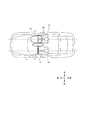
- FIG. 2 is a plan view showing a structure of a conventional vehicle in which an airbag device is mounted on a driver seat and a passenger seat, and enters at a predetermined angle ⁇ with respect to an object (obstacle) at a position shifted from the front. It shows how to do.
- FIG. 3 shows how the vehicle body rotates after colliding with an object (obstacle) from the state of FIG.
- the passenger 12 in the passenger seat slides beside the passenger seat airbag 18 and collides with the center console between the driver seat and the passenger seat.
- This brain injury index is called BRIC (BrainBRotational Injury Criteria).
- the present invention has been made in view of the above situation, and an object of the present invention is to provide an airbag device that can effectively restrain an occupant from moving obliquely forward with a simple structure.
- another object of the present invention is to provide a low-cost airbag device without increasing the output (capacity) of an inflator that generates inflation gas or minimizing the increase. There is to do.
- an airbag device is operated by a signal from a sensor that detects a collision of a vehicle and releases an inflation gas; and an airbag that is inflated and deployed by the inflation gas; Is provided.
- the airbag is connected to a first airbag that unfolds in front of an occupant seated on a seat and restrains the occupant from moving forward; And a second airbag that restrains the occupant from moving obliquely forward when deployed.
- the collision sensor can discriminate between a first collision mode that does not involve rotation of the vehicle and a second collision mode that involves rotation in a horizontal plane of the vehicle, and when the second collision mode occurs Only deploy the second airbag.
- the present invention configured as described above, it is possible to effectively restrain the occupant from moving obliquely forward, and to reduce the collision with the center console and further the injury caused by the rotation of the occupant's neck (head). be able to.
- the second airbag is configured to deploy only when the second collision mode occurs, the exhaust vent opening normally provided in the first airbag is omitted, or the second airbag By closing the exhaust vent opening when a collision mode occurs, it is possible to minimize the increase in the capacity of the inflator. That is, in the present invention, the inflation gas is efficiently used by selectively operating (deploying) a plurality of airbags.
- the third airbag is configured to be deployed only when the first collision mode occurs, In any collision mode, a 2/3 airbag may be deployed, and an increase in inflator capacity can be suppressed.
- vehicle rotation means rotation in a plane horizontal (parallel) to the ground on which the vehicle is traveling, that is, a rotation component around a rotation axis perpendicular to the ground. To do. It also includes the case where movement and rotation other than rotation in the horizontal plane occur at the same time. For example, it includes a case of rotating about the traveling direction as an axis like a roll over while rotating horizontally.
- FIG. 1 is a plan view showing the structure of a conventional vehicle in which an airbag device is mounted in a driver seat and a passenger seat, and enters at an angle of 0 ° with respect to an object (obstacle) at a position shifted from the front. It shows how to do.
- FIG. 2 is a plan view showing a structure of a conventional vehicle in which an airbag device is mounted on a driver seat and a passenger seat, and enters at a predetermined angle ⁇ with respect to an object (obstacle) at a position shifted from the front. It shows how to do.
- FIG. 1 is a plan view showing the structure of a conventional vehicle in which an airbag device is mounted in a driver seat and a passenger seat, and enters at an angle of 0 ° with respect to an object (obstacle) at a position shifted from the front. It shows how to do.
- FIG. 2 is a plan view showing a structure of a conventional vehicle in which an airbag device is mounted on a driver seat and
- FIG. 3 is a plan view showing the structure of a conventional vehicle in which an airbag device is mounted in the driver's seat and the passenger seat, and enters at a predetermined angle ⁇ with respect to an object (obstacle) at a position shifted from the front. Then, it shows how the car body rotates.
- FIG. 4 is a plan view showing a schematic configuration of a vehicle equipped with the airbag apparatus according to the present invention.
- FIG. 5 is a plan view showing the structure of a vehicle equipped with the airbag apparatus according to the present invention, and shows a state of colliding with an object (obstacle) from the front (first collision mode).
- FIG. 6 is a plan view showing the structure of a vehicle equipped with the airbag apparatus according to the present invention, and enters an object (obstacle) at a position shifted from the front in front at a predetermined angle ⁇ from the passenger seat side. Then, a state in which the vehicle body rotates (second collision mode) is shown.
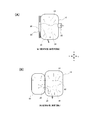
- FIG. 7 is an explanatory view showing an operating state of the airbag apparatus according to the first embodiment of the present invention, in which (A) shows a deployed state of the airbag in a first collision mode such as a frontal collision, and (B). Shows the deployed state of the airbag in a second collision mode such as an oblique collision.
- FIG. 8 is a schematic block diagram showing the configuration of the control system of the airbag apparatus according to the present invention.
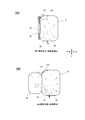
- FIG. 9 is an explanatory view showing an operating state of the airbag apparatus according to the second embodiment of the present invention, in which (A) shows a deployed state of the airbag in a first collision mode such as a frontal collision, and (B). Shows the deployed state of the airbag in a second collision mode such as an oblique collision.
- FIG. 10 is an explanatory view showing an operating state of the airbag apparatus according to the second embodiment of the present invention, in which (A) shows a deployed state of the airbag in a first collision mode such as a frontal collision, and (B). Shows the deployed state of the airbag in a second collision mode such as an oblique collision.
- FIG. 4 is a plan view showing a schematic configuration of a vehicle equipped with the airbag apparatus according to the present invention.
- the present invention employs a structure in which an auxiliary airbag 20 is connected to the side of the passenger seat airbag 18.
- the airbag device according to the present invention is configured to operate assuming at least two types of collision modes.
- FIG. 5 shows a state (first collision mode) in which a vehicle equipped with an airbag device according to the present invention collides against an object (obstacle) from the front.
- FIG. 6 shows that a vehicle equipped with an airbag device according to the present invention enters an object (obstacle) at a position deviated from the front from the front passenger side at a predetermined angle ⁇ , and then the vehicle body rotates.
- a state (second collision mode) is shown.
- the first collision mode is a mode in which the vehicle does not rotate in the horizontal plane due to the collision
- the second collision mode is a mode in which the vehicle rotates in the horizontal plane due to the collision.
- the passenger 12 in the passenger seat moves to the center console side between the passenger seat and the driver seat due to inertia.
- FIG. 7 is an explanatory view showing an operating state of the airbag apparatus according to the first embodiment of the present invention, in which (A) shows a deployed state of the airbag in a first collision mode such as a frontal collision, and (B). Shows a deployment body of an airbag in a second collision mode such as an oblique collision.
- the airbag apparatus according to the present embodiment includes a sensor (32) that detects a vehicle collision; an inflator 30 that operates according to a signal from the sensor (32) and discharges an inflation gas; and an air that is inflated and deployed by the inflation gas. Bags 18 and 20 are provided.
- the airbag is deployed in front of the occupant 12 seated in the passenger seat and restrains the occupant 12 from moving forward; the side of the first airbag 18 on the center side of the passenger compartment And a second airbag 20 that restrains the occupant 12 from moving obliquely forward when deployed.
- the collision sensor (32) can discriminate between the first collision mode that does not involve rotation of the vehicle and the second collision mode that involves rotation in the horizontal plane of the vehicle, and when the second collision mode occurs Only the second airbag 20 is deployed.
- a connecting portion between the first airbag 18 and the second airbag 20 is provided with a first vent 26 that is openable and closable that communicates with both airbags 18, 20.
- the gas flows from the airbag 18 into the second airbag 20. That is, the first vent 26 opens only when the second collision mode occurs.
- One end of a first tether 28 that controls opening and closing is connected to the first vent 26.
- the other end of the first tether 28 is connected to a housing (not shown) outside the airbag, and is cut when the second collision mode is detected.
- a second vent 22 that can be opened and closed is provided on the side of the first airbag 18 on the vehicle window side.
- One end of a second tether 24 for performing opening / closing control of the vent 22 is connected to the second vent 22.
- the other end of the second tether 24 is connected to the vehicle central side surface of the second airbag.
- FIG. 8 is a schematic block diagram showing the configuration of the control system of the airbag apparatus according to the present invention.
- the collision sensor 32 detects the occurrence of collision of the vehicle itself and discriminates between the first collision mode and the second collision mode. When the occurrence of a vehicle collision is detected by the collision sensor 32, a signal is sent to the inflator 30, and the inflator 30 is activated to release the inflation gas.
- the collision sensor 32 determines that the first collision mode is selected, the tether cutter 34 is not driven, and the first tether 28 is not cut.
- the tether cutter 34 is driven to cut the first tether 28.
- a well-known structure as disclosed in JP 2010-83175A can be adopted.
- the opening / closing control of the first vent 26 and the second vent 22 is performed by adjusting the tension of the tethers 28 and 24.
- the end of the tether is inserted into the periphery of the opening, the opening is closed by pulling the tether, and the opening is opened by loosening the tether. Yes.
- the inflator 30 when the first collision mode occurs, as shown in FIG. 7A, the inflator 30 is activated, and the first airbag 18 is first inflated. At this time, since the tether cutter 34 does not cut the first tether 28, the tension of the first tether 28 is maintained high, the first vent 26 remains closed, and the second airbag 20 Expansion gas does not flow. For this reason, the tension of the second tether 24 remains low, the second vent 22 is opened, and part of the gas is released from the second vent 22. The forward movement of the passenger 12 in the passenger seat is restrained by the inflated and deployed first airbag 18.
- the inflator 30 is operated, and the first airbag 18 is first inflated.
- the first tether 28 is cut by the tether cutter 34, the first tether 28 is loosened, the first vent 26 is opened, and the second airbag is passed from the first airbag 18 through the vent 26.
- the inflation gas flows through 20.
- the second airbag 20 is inflated, the second tether 24 is pulled, and the second vent 22 formed in the first airbag 18 is closed.
- the forward movement of the passenger 12 in the front passenger seat is restrained by the inflated and deployed first airbag 18, and at the same time, the second airbag 20 restrains the obliquely forward movement.
- FIG. 9 is an explanatory view showing an operating state of the airbag apparatus according to the second embodiment of the present invention, in which (A) shows a deployed state of the airbag in a first collision mode such as a frontal collision, and (B). Shows a deployment body of an airbag in a second collision mode such as an oblique collision.
- the airbag apparatus according to the present embodiment has the same basic structure as that of the first embodiment described above, but differs in the structure and operation of the vent mechanism. In addition, about the structure and operation
- the connecting portion between the first airbag 18 and the second airbag 20 is provided with a first vent 26 that can be opened and closed communicating with both airbags 18, 20.
- the gas is configured to flow from the first airbag 18 into the second airbag 20 in the case of two collision modes. That is, the first vent 26 opens only when the second collision mode occurs.
- One end of a first tether 28 that controls opening and closing is connected to the first vent 26.
- the other end of the first tether 28 is connected to a housing (not shown) outside the airbag, and is cut when the second collision mode is detected.
- a second vent opening 122 that can be opened and closed is provided in the upper portion of the first airbag 18 on the vehicle center side.
- the second vent opening 122 is controlled to be opened and closed by the second tether 124.
- One end of the second tether 124 is connected near the inner upper end of the first airbag 18, and the other end passes through the second vent opening 122 and comes out of the airbag, and the outer surface of the second airbag It is connected near the top of
- the opening / closing control of the first vent 26 and the second vent 122 is performed by adjusting the tension of the tethers 28 and 124.
- the vent 26 like the drawstring bag, the end of the tether is inserted into the periphery of the opening portion, the opening is closed by pulling the tether, and the opening is opened by loosening the tether.
- the second vent opening 122 takes the form of a so-called patch plug vent. The vent is closed by covering the opening with the flap, and the opening is opened by loosening the flap.
- the inflator 30 when the first collision mode occurs, as shown in FIG. 9A, the inflator 30 is activated, and the first airbag 18 is first inflated. At this time, since the tether cutter 34 does not cut the first tether 28, the tension of the first tether 28 is maintained high, the first vent 26 remains closed, and the second airbag 20 Expansion gas does not flow. Further, the tension of the second tether 124 remains low, the second vent 122 is opened, and a part of the gas is released from the second vent 122. The forward movement of the passenger 12 in the passenger seat is restrained by the inflated and deployed first airbag 18.
- the inflator 30 is activated, and the first airbag 18 is first inflated.
- the first tether 28 is cut by the tether cutter 34, the tension of the first tether 28 is loosened, the first vent 26 is opened, and the second tether 28 is opened from the first airbag 18 through the vent 26.
- the inflation gas flows through the airbag 20.
- the second airbag 20 is inflated, the second tether 124 is pulled, and the second vent 122 formed in the first airbag 18 is closed. Then, the forward movement of the passenger 12 in the passenger seat is restrained by the inflated and deployed first airbag 18, and the obliquely forward movement is restrained by the second airbag 20.
- the structure is such that gas is not exhausted from the first airbag 18 when the second airbag 20 is deployed, so that the required amount of gas can be minimized. It becomes. As a result, an increase in the capacity of the inflator 30 due to the provision of a plurality of airbags can be suppressed.
- FIG. 10 is an explanatory view showing an operating state of the airbag apparatus according to the third embodiment of the present invention, in which (A) shows a deployed state of the airbag in a first collision mode such as a frontal collision, and (B). Shows a deployment body of an airbag in a second collision mode such as an oblique collision.
- the airbag apparatus according to the present embodiment uses three airbags. Note that the description of the same configuration and operation as those in the first and second embodiments is omitted.
- a third airbag 222 connected to the window side portion of the first airbag 18 is further provided.
- the third airbag 222 is configured to be deployed only when the first collision mode occurs.
- the front airbag 218 and the vehicle window side airbag 222 are deployed to restrain movement of the occupant 12 to the front and outside.
- the airbag 218 on the front side and the airbag 220 on the center side of the vehicle are deployed to restrain movement of the occupant 12 toward the front side and the middle side (center console side).
- a connecting portion between the first airbag 218 and the second airbag 220 has a first vent 226 that can be opened and closed communicating with both airbags 218 and 220. It is provided so that gas flows from the first airbag 218 into the second airbag 220 in the second collision mode. That is, the first vent 226 is opened only when the second collision mode occurs.
- One end of a first tether 232 that controls opening and closing is connected to the first vent 226.
- the other end of the first tether 232 is connected to a housing (not shown) outside the airbag, and is cut when the second collision mode is detected.
- a connecting portion between the first airbag 218 and the third airbag 222 is provided with a second vent 230 that is openable and closable that communicates with both airbags 218, 222.
- the gas flows from the airbag 218 into the third airbag 222. That is, the second vent 230 opens only when the first collision mode occurs.
- One end of a second tether 228 that controls opening and closing is connected to the second vent 230.
- the other end of the second tether 228 passes through the first airbag 218 and is connected to the inner side surface of the second airbag 220.
- the opening / closing control of the first vent 226 and the second vent 230 is performed by adjusting the tension of the tethers 232 and 228.
- the end of the tether is inserted into the periphery of the opening, the opening is closed by pulling the tether, and the opening is opened by loosening the tether. Yes.
- the inflator 30 when the first collision mode occurs, as shown in FIG. 10A, the inflator 30 is activated, and the first airbag 218 is first inflated. At this time, since the tether cutter 34 does not cut the first tether 232, the tension of the first tether 232 is maintained high, the first vent 226 remains closed, and the second airbag 220 has Expansion gas does not flow. Further, the tension of the second tether 228 remains low, the second vent 230 is opened, a part of the gas flows from the second vent 230 into the third airbag 222, and the third air The bag 222 is deployed. The forward movement of the passenger 12 in the passenger seat is restrained by the inflated and deployed first airbag 218 and the third airbag 222.
- the inflator 30 is activated, and the first airbag 18 is first inflated.
- the first tether 232 is cut by the tether cutter 34, the first tether 232 is loosened, the first vent 226 is opened, and the second airbag is passed from the first airbag 218 through the vent 226.
- the inflation gas flows through 220.
- the second airbag 220 is inflated, the second tether 228 is pulled, so that the second vent 230 is closed and the third airbag 222 is not deployed.
- the forward movement of the passenger 12 in the passenger seat is restrained by the inflated and deployed first airbag 218, and at the same time the obliquely forward movement is restrained by the second airbag 220.
- the direction of vehicle rotation can be detected by the collision sensor 32, and the deployment of the first to third airbags 218, 220, and 222 can be controlled more precisely accordingly.
- the third airbag 222 is deployed only when the vehicle rotates counterclockwise as opposed to the state of FIG. 6, and in the case of a collision without rotation (first collision mode), the first It is also possible to configure so that only the airbag 218 is deployed.
Landscapes
- Engineering & Computer Science (AREA)
- Mechanical Engineering (AREA)
- Physics & Mathematics (AREA)
- Fluid Mechanics (AREA)
- Air Bags (AREA)
Abstract
Description
Claims (6)
- 車両の衝突を検出するセンサからの信号によって作動し、膨張ガスを放出するインフレータと;
前記膨張ガスによって膨張・展開するエアバッグとを備え、
前記エアバッグは、シートに着座した乗員の正面に展開して当該乗員の前方への移動を拘束する第1のエアバッグと;前記第1のエアバッグの車室中央側の側部に連結され、展開時に当該乗員の斜め前方への移動を拘束する第2のエアバッグとを備え、
前記衝突センサは、水平面内での車両の回転を伴わない第1の衝突形態と、水平面内での車両の回転を伴う第2の衝突形態とを判別可能であり、
前記第2の衝突形態が発生した場合にのみ、前記第2のエアバッグを展開させることを特徴とするエアバッグ装置。 - 前記第1のエアバッグと第2のエアバッグの連結部には、両方のエアバッグに連通する開閉可能な第1のベント開口が形成され、
前記第2の衝突形態の時に前記第1のエアバッグから前記第2のエアバッグにガスが流れ込むように構成されていることを特徴とする請求項1に記載のエアバッグ装置。 - 前記第1のベント開口は、前記第2の衝突形態が発生した時のみ開くことを特徴とする請求項2に記載のエアバッグ装置。
- 前記第1のベント開口には、開閉を調整する第1のテザーが連結され、
前記第1のテザーは、前記第2の衝突形態が検出されたときに切断されることを特徴とする3に記載のエアバッグ装置。 - 前記第1のエアバッグの窓側の側部に連結された第3のエアバッグを更に備えたことを特徴とする請求項1乃至4の何れか一項に記載のエアバッグ装置。
- 前記第3のエアバッグは、前記第1の衝突形態が発生した場合にのみ展開することを特徴とする請求項5に記載のエアバッグ装置。
Priority Applications (2)
| Application Number | Priority Date | Filing Date | Title |
|---|---|---|---|
| US15/319,904 US10246042B2 (en) | 2014-06-25 | 2015-05-01 | Air bag device |
| JP2016529160A JP6345241B2 (ja) | 2014-06-25 | 2015-05-01 | エアバッグ装置 |
Applications Claiming Priority (2)
| Application Number | Priority Date | Filing Date | Title |
|---|---|---|---|
| JP2014130828 | 2014-06-25 | ||
| JP2014-130828 | 2014-06-25 |
Publications (1)
| Publication Number | Publication Date |
|---|---|
| WO2015198717A1 true WO2015198717A1 (ja) | 2015-12-30 |
Family
ID=54937816
Family Applications (1)
| Application Number | Title | Priority Date | Filing Date |
|---|---|---|---|
| PCT/JP2015/063150 Ceased WO2015198717A1 (ja) | 2014-06-25 | 2015-05-01 | エアバッグ装置 |
Country Status (3)
| Country | Link |
|---|---|
| US (1) | US10246042B2 (ja) |
| JP (1) | JP6345241B2 (ja) |
| WO (1) | WO2015198717A1 (ja) |
Cited By (5)
| Publication number | Priority date | Publication date | Assignee | Title |
|---|---|---|---|---|
| JP2017100685A (ja) * | 2015-12-04 | 2017-06-08 | トヨタ自動車株式会社 | 助手席用エアバッグ装置 |
| CN107856631A (zh) * | 2016-09-21 | 2018-03-30 | 现代自动车株式会社 | 用于车辆的帘式气囊 |
| CN108688604A (zh) * | 2017-04-05 | 2018-10-23 | 福特全球技术公司 | 约束系统 |
| CN109318852A (zh) * | 2017-08-01 | 2019-02-12 | 通用汽车环球科技运作有限责任公司 | 具有用于次级压力室的内部阀门的气囊垫 |
| JPWO2023008303A1 (ja) * | 2021-07-27 | 2023-02-02 |
Families Citing this family (8)
| Publication number | Priority date | Publication date | Assignee | Title |
|---|---|---|---|---|
| KR102434047B1 (ko) * | 2017-10-11 | 2022-08-19 | 현대모비스 주식회사 | 에어백 장치 |
| US11192512B2 (en) * | 2018-08-31 | 2021-12-07 | Joyson Safety Systems Acquisition Llc | Airbag arrangement |
| US10730472B2 (en) | 2018-10-23 | 2020-08-04 | Trw Vehicle Safety Systems Inc. | Airbag and method for protecting an occupant of a vehicle |
| JP7074702B2 (ja) * | 2019-03-07 | 2022-05-24 | トヨタ自動車株式会社 | 車両用エアバッグ装置 |
| CN112172731A (zh) * | 2019-07-05 | 2021-01-05 | 标致雪铁龙汽车股份有限公司 | 一种车辆主动气帘设备及车辆 |
| US11014522B2 (en) | 2019-10-08 | 2021-05-25 | Ford Global Technologies, Llc | Dual-chambered side and front airbag |
| US11498513B2 (en) * | 2021-03-26 | 2022-11-15 | ZF Passive Safety Systems US Inc. | Airbag with passive and active vents |
| US11975674B2 (en) * | 2021-12-17 | 2024-05-07 | Waymo Llc | Airbag systems for autonomous vehicles |
Citations (3)
| Publication number | Priority date | Publication date | Assignee | Title |
|---|---|---|---|---|
| JPH0565706U (ja) * | 1992-02-19 | 1993-08-31 | 三菱自動車工業株式会社 | エアバッグ装置 |
| JP2008044594A (ja) * | 2006-07-19 | 2008-02-28 | Toyoda Gosei Co Ltd | エアバッグ装置 |
| JP2012505783A (ja) * | 2008-10-14 | 2012-03-08 | オートリブ エーエスピー,インコーポレイティド | テザー解放機構のための装着ブラケット |
Family Cites Families (44)
| Publication number | Priority date | Publication date | Assignee | Title |
|---|---|---|---|---|
| US4262931A (en) | 1979-09-18 | 1981-04-21 | Ford Motor Company | Air bag restraint system |
| US5007411A (en) | 1989-04-12 | 1991-04-16 | The Kendall Company | Device for applying compressive pressures against a patient's limb |
| JP2561370B2 (ja) | 1990-06-21 | 1996-12-04 | 日産自動車株式会社 | エアバッグ装置 |
| JPH0565706A (ja) | 1991-09-09 | 1993-03-19 | Nissan Motor Co Ltd | 信号装置 |
| JP3314091B2 (ja) | 1992-08-28 | 2002-08-12 | マツダ株式会社 | 自動車のエアバッグ配設構造 |
| JP3278463B2 (ja) | 1992-09-01 | 2002-04-30 | マツダ株式会社 | 自動車のエアバッグ配設構造 |
| JPH0872261A (ja) | 1994-09-02 | 1996-03-19 | Canon Inc | 処理液タンク、インクジェットカートリッジおよびインクジェット記録装置 |
| JPH08268204A (ja) | 1995-03-31 | 1996-10-15 | Nissan Motor Co Ltd | 乗り物用エアバッグ装置 |
| JPH1071920A (ja) | 1996-08-30 | 1998-03-17 | Denso Corp | 助手席用エアバッグ装置 |
| JP3598012B2 (ja) | 1999-03-31 | 2004-12-08 | 日産車体株式会社 | エアバッグ装置 |
| US6669229B2 (en) | 2001-03-22 | 2003-12-30 | General Motors Corporation | Automotive vehicle air bag system |
| JP2003182328A (ja) | 2001-12-21 | 2003-07-03 | Pacific Ind Co Ltd | タイヤ状態監視装置の送信機及びタイヤ状態監視装置 |
| JP2003182500A (ja) | 2001-12-25 | 2003-07-03 | Takata Corp | 乗員保護装置 |
| JP4274742B2 (ja) | 2002-05-22 | 2009-06-10 | タカタ株式会社 | エアバッグ及びエアバッグ装置 |
| US7083191B2 (en) | 2002-09-16 | 2006-08-01 | Trw Vehicle Safety Systems Inc. | Air bag module with vent controlled by tether |
| US7404575B2 (en) | 2003-07-14 | 2008-07-29 | Toyoda Gosei Co., Ltd. | Air bag apparatus |
| JP4096847B2 (ja) | 2003-09-16 | 2008-06-04 | 豊田合成株式会社 | 助手席用エアバッグ装置 |
| JP2005247118A (ja) | 2004-03-03 | 2005-09-15 | Toyoda Gosei Co Ltd | 助手席用エアバッグ |
| JP4419657B2 (ja) | 2004-04-15 | 2010-02-24 | 日産自動車株式会社 | 車両用乗員拘束装置 |
| JP4244896B2 (ja) | 2004-09-22 | 2009-03-25 | トヨタ自動車株式会社 | エアバッグ装置 |
| JP2006232267A (ja) | 2005-02-22 | 2006-09-07 | Takata Corp | エアバッグクッション |
| JP4870369B2 (ja) | 2005-03-17 | 2012-02-08 | 日本プラスト株式会社 | 車両用エアバッグ装置 |
| JP2006327505A (ja) | 2005-05-27 | 2006-12-07 | Nippon Plast Co Ltd | 助手席用エアバッグ装置 |
| US7625008B2 (en) | 2005-10-17 | 2009-12-01 | Key Safety Systems, Inc. | Air bag with groove or recess, open or partially covered |
| EP1775177B1 (en) | 2005-10-17 | 2015-05-13 | Key Safety Systems, Inc. | Airbag forming a recess |
| US7152880B1 (en) | 2005-10-17 | 2006-12-26 | Key Safety Systems, Inc. | Grooved air bag |
| JP2007216733A (ja) | 2006-02-14 | 2007-08-30 | Toyota Motor Corp | 車両用エアバッグ装置 |
| MX2007003946A (es) | 2006-04-07 | 2008-11-26 | Key Safety Systems Inc | Bolsa de aire con ranura vertical. |
| JP4841399B2 (ja) | 2006-10-31 | 2011-12-21 | 日本プラスト株式会社 | エアバッグ及びエアバッグの折畳方法 |
| JP4613913B2 (ja) | 2007-01-23 | 2011-01-19 | トヨタ自動車株式会社 | 車両のエアバック装置 |
| DE102007032761A1 (de) | 2007-07-13 | 2009-01-15 | Deutsches Zentrum für Luft- und Raumfahrt e.V. | Prüfvorrichtung und Verfahren zur Prüfung einer für eine Tieftemperaturanwendung vorgesehenen Dichtung |
| JP2009120114A (ja) | 2007-11-16 | 2009-06-04 | Toyoda Gosei Co Ltd | 助手席用エアバッグ装置 |
| JP4959616B2 (ja) | 2008-03-25 | 2012-06-27 | オートリブ ディベロップメント エービー | 可変排気孔付きエアバッグ装置 |
| JP5366591B2 (ja) | 2009-02-27 | 2013-12-11 | 日本プラスト株式会社 | エアバッグ及びエアバッグ装置 |
| JP5445406B2 (ja) | 2010-09-06 | 2014-03-19 | トヨタ自動車株式会社 | 助手席用エアバッグ装置 |
| JP5572597B2 (ja) | 2011-06-30 | 2014-08-13 | 富士重工業株式会社 | 乗員保護装置 |
| JP5743798B2 (ja) | 2011-08-10 | 2015-07-01 | タカタ株式会社 | ストラップ保持装置及びエアバッグ装置 |
| JP5747799B2 (ja) | 2011-11-30 | 2015-07-15 | トヨタ自動車株式会社 | 助手席用エアバッグ装置 |
| US9527469B2 (en) | 2011-12-29 | 2016-12-27 | Toyota Jidosha Kabushiki Kaisha | Vehicle airbag system |
| DE102012018450B4 (de) | 2012-09-18 | 2015-02-12 | Autoliv Development Ab | Personenkraftwagen mit einem sich am Fahrzeughimmel abstützenden Gassack eines Beifahrer- Frontgassackmoduls und Gassack für einen solchen Personenkraftwagen |
| JP6085470B2 (ja) | 2012-12-21 | 2017-02-22 | スズキ株式会社 | エアバッグ装置 |
| JP5850011B2 (ja) * | 2013-08-23 | 2016-02-03 | トヨタ自動車株式会社 | 車両用乗員保護装置 |
| US9162645B2 (en) * | 2013-12-20 | 2015-10-20 | Ford Global Technologies, Llc | High pressure airbag for oblique impact modes |
| US8882138B1 (en) | 2014-03-26 | 2014-11-11 | Autoliv Asp, Inc. | Center airbag |
-
2015
- 2015-05-01 US US15/319,904 patent/US10246042B2/en active Active
- 2015-05-01 WO PCT/JP2015/063150 patent/WO2015198717A1/ja not_active Ceased
- 2015-05-01 JP JP2016529160A patent/JP6345241B2/ja active Active
Patent Citations (3)
| Publication number | Priority date | Publication date | Assignee | Title |
|---|---|---|---|---|
| JPH0565706U (ja) * | 1992-02-19 | 1993-08-31 | 三菱自動車工業株式会社 | エアバッグ装置 |
| JP2008044594A (ja) * | 2006-07-19 | 2008-02-28 | Toyoda Gosei Co Ltd | エアバッグ装置 |
| JP2012505783A (ja) * | 2008-10-14 | 2012-03-08 | オートリブ エーエスピー,インコーポレイティド | テザー解放機構のための装着ブラケット |
Cited By (9)
| Publication number | Priority date | Publication date | Assignee | Title |
|---|---|---|---|---|
| JP2017100685A (ja) * | 2015-12-04 | 2017-06-08 | トヨタ自動車株式会社 | 助手席用エアバッグ装置 |
| CN107856631A (zh) * | 2016-09-21 | 2018-03-30 | 现代自动车株式会社 | 用于车辆的帘式气囊 |
| CN107856631B (zh) * | 2016-09-21 | 2021-10-01 | 现代自动车株式会社 | 用于车辆的帘式气囊 |
| CN108688604A (zh) * | 2017-04-05 | 2018-10-23 | 福特全球技术公司 | 约束系统 |
| GB2562887A (en) * | 2017-04-05 | 2018-11-28 | Ford Global Tech Llc | Restraint System |
| CN109318852A (zh) * | 2017-08-01 | 2019-02-12 | 通用汽车环球科技运作有限责任公司 | 具有用于次级压力室的内部阀门的气囊垫 |
| JPWO2023008303A1 (ja) * | 2021-07-27 | 2023-02-02 | ||
| WO2023008303A1 (ja) * | 2021-07-27 | 2023-02-02 | オートリブ ディベロップメント エービー | 乗員拘束装置 |
| JP7620710B2 (ja) | 2021-07-27 | 2025-01-23 | オートリブ ディベロップメント エービー | 乗員拘束装置 |
Also Published As
| Publication number | Publication date |
|---|---|
| US20170120856A1 (en) | 2017-05-04 |
| US10246042B2 (en) | 2019-04-02 |
| JP6345241B2 (ja) | 2018-06-20 |
| JPWO2015198717A1 (ja) | 2017-04-20 |
Similar Documents
| Publication | Publication Date | Title |
|---|---|---|
| JP6345241B2 (ja) | エアバッグ装置 | |
| US10730472B2 (en) | Airbag and method for protecting an occupant of a vehicle | |
| JP5850011B2 (ja) | 車両用乗員保護装置 | |
| JP6491739B2 (ja) | エアバッグ装置 | |
| KR102683790B1 (ko) | 차량의 시트에어백 | |
| KR101664588B1 (ko) | 차량용 조수석 에어백 장치 | |
| JP2018135098A (ja) | エアバッグ装置 | |
| JP6314897B2 (ja) | 車両用運転席エアバッグ装置 | |
| WO2015156088A1 (ja) | エアバッグ装置 | |
| JP2006298119A (ja) | エアバッグ装置、乗員保護システム、車両 | |
| US8684403B2 (en) | Active airbag venting system | |
| KR20100127982A (ko) | 도어 회전이 제한되는 루프 에어백 장치 | |
| WO2018193688A1 (ja) | エアバッグ装置 | |
| WO2016147683A1 (ja) | エアバッグ装置 | |
| KR20160025369A (ko) | 차량의 동승석 에어백 | |
| JP6642303B2 (ja) | 助手席用エアバッグ装置 | |
| JP4379433B2 (ja) | 膝保護用エアバッグ装置 | |
| US11498513B2 (en) | Airbag with passive and active vents | |
| KR101684988B1 (ko) | 차량용 에어백 장치 | |
| KR101724965B1 (ko) | 차량용 에어백 장치 | |
| JP7169258B2 (ja) | サイドエアバッグ装置 | |
| KR20180062494A (ko) | 차량용 전방에어백 | |
| KR20210037039A (ko) | 차량용 에어백 장치 | |
| JP6697805B2 (ja) | エアバッグ装置 | |
| JP6762909B2 (ja) | サイドエアバッグ装置 |
Legal Events
| Date | Code | Title | Description |
|---|---|---|---|
| 121 | Ep: the epo has been informed by wipo that ep was designated in this application |
Ref document number: 15812670 Country of ref document: EP Kind code of ref document: A1 |
|
| ENP | Entry into the national phase |
Ref document number: 2016529160 Country of ref document: JP Kind code of ref document: A |
|
| WWE | Wipo information: entry into national phase |
Ref document number: 15319904 Country of ref document: US |
|
| NENP | Non-entry into the national phase |
Ref country code: DE |
|
| 122 | Ep: pct application non-entry in european phase |
Ref document number: 15812670 Country of ref document: EP Kind code of ref document: A1 |