WO2015181900A1 - 回転電機 - Google Patents
回転電機 Download PDFInfo
- Publication number
- WO2015181900A1 WO2015181900A1 PCT/JP2014/064034 JP2014064034W WO2015181900A1 WO 2015181900 A1 WO2015181900 A1 WO 2015181900A1 JP 2014064034 W JP2014064034 W JP 2014064034W WO 2015181900 A1 WO2015181900 A1 WO 2015181900A1
- Authority
- WO
- WIPO (PCT)
- Prior art keywords
- brake
- electrical machine
- rotating electrical
- shaft
- yoke
- Prior art date
- Legal status (The legal status is an assumption and is not a legal conclusion. Google has not performed a legal analysis and makes no representation as to the accuracy of the status listed.)
- Ceased
Links
Images
Classifications
-
- F—MECHANICAL ENGINEERING; LIGHTING; HEATING; WEAPONS; BLASTING
- F16—ENGINEERING ELEMENTS AND UNITS; GENERAL MEASURES FOR PRODUCING AND MAINTAINING EFFECTIVE FUNCTIONING OF MACHINES OR INSTALLATIONS; THERMAL INSULATION IN GENERAL
- F16D—COUPLINGS FOR TRANSMITTING ROTATION; CLUTCHES; BRAKES
- F16D55/00—Brakes with substantially-radial braking surfaces pressed together in axial direction, e.g. disc brakes
- F16D55/02—Brakes with substantially-radial braking surfaces pressed together in axial direction, e.g. disc brakes with axially-movable discs or pads pressed against axially-located rotating members
- F16D55/22—Brakes with substantially-radial braking surfaces pressed together in axial direction, e.g. disc brakes with axially-movable discs or pads pressed against axially-located rotating members by clamping an axially-located rotating disc between movable braking members, e.g. movable brake discs or brake pads
- F16D55/224—Brakes with substantially-radial braking surfaces pressed together in axial direction, e.g. disc brakes with axially-movable discs or pads pressed against axially-located rotating members by clamping an axially-located rotating disc between movable braking members, e.g. movable brake discs or brake pads with a common actuating member for the braking members
- F16D55/225—Brakes with substantially-radial braking surfaces pressed together in axial direction, e.g. disc brakes with axially-movable discs or pads pressed against axially-located rotating members by clamping an axially-located rotating disc between movable braking members, e.g. movable brake discs or brake pads with a common actuating member for the braking members the braking members being brake pads
-
- H—ELECTRICITY
- H02—GENERATION; CONVERSION OR DISTRIBUTION OF ELECTRIC POWER
- H02K—DYNAMO-ELECTRIC MACHINES
- H02K7/00—Arrangements for handling mechanical energy structurally associated with dynamo-electric machines, e.g. structural association with mechanical driving motors or auxiliary dynamo-electric machines
- H02K7/10—Structural association with clutches, brakes, gears, pulleys or mechanical starters
- H02K7/102—Structural association with clutches, brakes, gears, pulleys or mechanical starters with friction brakes
Definitions
- the disclosed embodiment relates to a rotating electrical machine.
- Patent Document 1 describes a rotating electric machine having a rotor and a stator provided with a motor shaft, and an electromagnetic brake device for braking the non-load side of the motor shaft.
- the above prior art has a structure in which the rotating electrical machine and the electromagnetic brake device are arranged in parallel in the axial direction, and therefore the axial dimension tends to increase.
- the axial dimension tends to increase.
- the present invention has been made in view of such problems, and an object thereof is to provide a rotating electrical machine including a brake that can be thinned in the axial direction.
- an electromagnetic part including a stator and configured to rotate a shaft, and at least a part of the electromagnetic part positioned on one side in the axial direction of the electromagnetic part Is applied to a rotating electric machine having a brake portion arranged to overlap the stator in the radial direction and configured to brake the shaft.
- an electromagnetic unit including a stator and configured to rotate a shaft, a brake unit configured to brake the shaft, the stator and the A rotating electrical machine having a means for connecting the electromagnetic part and the brake part so that at least a part of the brake part overlaps in the radial direction is applied.
- the rotating electrical machine equipped with the brake can be thinned in the axial direction.
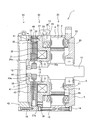
- the rotating electrical machine 1 includes an electromagnetic unit 20, a brake unit 30, and an encoder unit 50.
- the brake unit 30 is disposed on the anti-load side of the electromagnetic unit 20 (an example of one side in the axial direction; the left side in FIG. 1), and the encoder unit 50 is disposed on the further anti-load side of the brake unit 30.
- positioning of the electromagnetic part 20, the brake part 30, and the encoder part 50 is not limited above.
- at least one of the brake unit 30 and the encoder unit 50 may be disposed on the load side (right side in FIG. 1) of the electromagnetic unit 20.
- the electromagnetic unit 20 and the brake unit 30 are disposed adjacent to each other in the axial direction.
- the rotating electrical machine 1 may be a motor or a generator.
- load side refers to the direction in which the shaft 10 protrudes from the rotating electrical machine 1 (right side in FIG. 1)
- anti-load side refers to the opposite direction of the load side, that is, in this example.
- the direction (left side in FIG. 1) in which the encoder unit 50 is disposed with respect to the rotating electrical machine 1 is indicated.
- the electromagnetic unit 20 includes a stator 2 provided inside the cylindrical frame 4 and a rotor 3 provided on the shaft 10, and is configured to rotate the shaft 10.
- the stator 2 has an annular stator core 21 provided on the inner peripheral surface of the frame 4, and a plurality of stator windings 23 arranged on the stator core 21 in the circumferential direction.
- the stator winding 23 is wound around a bobbin 22, and the bobbin 22 is attached to the stator core 21.
- the rotor 3 is provided on the outer peripheral surface of the shaft 10.
- the rotor 3 includes an annular rotor core 27 disposed with a predetermined magnetic gap from the stator core 21, and a plurality of permanent magnets 28 disposed inside the rotor core 27.
- the permanent magnet 28 may be installed on the outer peripheral surface of the rotor core 27.
- the plurality of permanent magnets 28 are arranged on the rotor core 27 so that the magnetic poles formed on the outer periphery of the rotor core 27 alternately repeat the N pole and the S pole in the circumferential direction.
- a load side bracket 5 is provided on the load side (right side in FIG. 1) of the frame 4.
- a load side bearing 6 is fixed to the load side bracket 5.
- the outer peripheral portion of the load side bracket 5 is fixed to the frame 4 by a plurality of bolts 14.
- An anti-load side bearing 7 (an example of a first bearing) is fixed to the inner periphery of a yoke 32 (details will be described later) of the brake unit 30.
- An outer peripheral portion (a flange portion 37 described later) of the yoke 32 is fixed to the frame 4 by a plurality of bolts 15.
- the shaft 10 is rotatably supported by the load side bearing 6 and the anti-load side bearing 7.
- the electromagnetic part 20 has a resin part 25 that seals the stator 2.
- the resin portion 25 covers the periphery of the stator 2 including the stator core 21, the bobbin 22, the stator winding 23, and the connection portion 24.
- an alternating current is supplied to the stator winding 23 of the stator 2 from an external power source (not shown) via the connection unit 24.
- the stator winding 23 generates a rotating magnetic field, and the generated rotating magnetic field acts on the field magnetic flux of the permanent magnet 28 of the rotor 3, thereby generating a thrust in the circumferential direction on the rotor 3, and the shaft 10 rotates.
- the encoder unit 50 includes an encoder 12 and an encoder cover 45 that houses the encoder 12.
- the encoder 12 is disposed at the end of the shaft 10 on the side opposite to the load (an example of one side in the axial direction) and detects the rotational position of the shaft 10.
- the encoder 12 may be either magnetic or optical, or may include both.
- the outer periphery of the encoder cover 45 is fixed to the brake housing 43 by a plurality of bolts 16.
- the brake unit 30 is configured to brake the shaft 10.
- the brake unit 30 is configured as an electromagnetic brake (in this example, a non-excitation operation type brake).
- the brake unit 30 includes a brake coil 31, a yoke 32 that is a field core, a brake disk 33, an armature 34, and a side plate 35.
- the brake disk 33, the armature 34, and the side plate 35 are arranged in this order between the yoke 32 and the encoder unit 50 in the order of the armature 34, the brake disk 33, and the side plate 35 from the load side to the anti-load side.
- the brake part 30 is arranged so that at least a part thereof overlaps the stator 2 of the electromagnetic part 20 in the radial direction.
- at least a part of the yoke 32 is disposed so as to overlap the stator 2 in the radial direction.
- the yoke 32 has a protruding portion 36, and the protruding portion 36 is inserted from the anti-load side to the inside of the resin portion 25 in the radial direction, so that the protruding portion 36 has a diameter of the stator 2. It is arranged so as to overlap inside in the direction.
- the resin part 25 and the protrusion part 36 may be concavo-convexly fitted with no gap, or may be concavo-convexly fitted with a slight gap.
- the protrusion 36 has an annular recess 36a that opens to the opposite load side, and the brake coil 31 is accommodated in the recess 36a.
- the yoke 32 has a flange portion 37 extending outward in the radial direction from the protruding portion 36.
- the outer diameter of the flange portion 37 is substantially equal to that of the frame 4 and the resin portion 25, and the outer peripheral surface thereof is exposed on the surface of the rotating electrical machine 1.
- the connector 13 to which a motor cable (not shown) is connected is installed across the outer peripheral surface of the resin portion 25 and the outer peripheral surface of the flange portion 37.
- the flange portion 37 is formed with a plurality of spring recesses 37a formed at appropriate intervals in the circumferential direction, and a coil spring 38 is accommodated in each spring recess 37a.
- the coil spring 38 urges the armature 34 toward the anti-load side (brake disc 33 side).
- the anti-load side bearing 7 is fixed to the opening 32 a on the inner periphery of the yoke 32.
- the anti-load side bearing 7 is positioned by an annular projecting member 17 and a leaf spring 18 provided in the opening 32a.
- the brake disc 33 has a structure in which, for example, a friction material is provided on both sides of a disc-like disc.
- the brake disc 33 is provided on the shaft 10 so as to be movable in the axial direction and non-rotatable in the circumferential direction by fitting a spline portion in the axial direction to a hub 39 fixed on the opposite load side of the shaft 10.
- the armature 34 is, for example, a disk-shaped member made of an appropriate magnetic material (for example, a steel plate).
- the armature 34 is provided so as to be movable in the axial direction and non-rotatable in the circumferential direction by inserting a cylindrical collar 40 fixed to the yoke 32 through the outer peripheral portion.
- the side plate 35 is, for example, a disk-shaped member made of an appropriate material such as iron, aluminum, or composite carbon fiber material.
- the outer peripheral portion of the side plate 35 is fixed to the flange portion 37 of the yoke 32 by a plurality of fixing bolts 41 inserted through the collar 40.
- the dimension of the brake disk 33 in the radial direction is set to be as large as possible without contacting the collar 40.
- the brake unit 30 has a brake housing 43 that accommodates the brake disc 33 and the like.
- the brake housing 43 is formed with an insertion hole 43a through which an end of the shaft 10 on the side opposite to the load (one example in the axial direction) is inserted, and a bearing is provided in a gap between the insertion hole 43a and the outer periphery of the shaft 10. 44 (an example of a second bearing) is installed.
- the bearing 44 has an outer ring fixed to the brake housing 43 and an inner ring fixed to the shaft 10, and functions as a seal member that prevents inflow of brake powder generated in the brake housing 43 to the encoder unit 50 side.
- the brake housing 43 is fixed to the yoke 32 by a fixing bolt (not shown).
- the armature 34 is attracted to the yoke 32 against the urging force of the coil spring 38 and separated from the brake disk 33, and the braking of the shaft 10 is released.
- the armature 34 moves to the anti-load side by the urging force of the coil spring 38, the brake disc 33 is sandwiched between the armature 34 and the side plate 35, and the shaft 10 Is braked.
- the concave-convex fitting structure of the resin portion 25 of the electromagnetic portion 20 and the protruding portion 36 of the brake portion 30 and the bolt 15 are arranged so that at least a part of the stator and the brake portion overlap in the radial direction.
- the brake unit 30 is located on the non-load side of the electromagnetic unit 20. At this time, since at least a part of the brake part 30 is arranged so as to overlap the stator 2 in the radial direction, the electromagnetic part 20 and the brake part 30 are arranged in parallel in the axial direction (without overlapping in the radial direction). The axial dimension of the rotating electrical machine 1 can be reduced compared to the case where the rotating electrical machine 1 is used. Therefore, the rotary electric machine 1 can be thinned in the axial direction.
- the brake unit 30 includes the brake coil 31 and the yoke 32, and at least a part of the yoke 32 is disposed so as to overlap the stator 2 in the radial direction.
- the brake unit 30 is an electromagnetic brake having a brake coil 31 and a yoke 32.
- the brake disk 33 can be arranged so that the radial dimension is not limited by the stator 2.
- the radial direction dimension of the brake disc 33 can be enlarged and the braking function of the brake part 30 can be improved.
- the electromagnetic part 20 includes a resin part 25 that seals the stator 2, and the yoke 32 is a protruding part that accommodates the brake coil 31 and is inserted radially inside the resin part 25. 36.
- the electromagnetic portion 20 and the brake portion 30 can be roughly positioned by the concave and convex fitting between the protruding portion 36 of the yoke 32 and the resin portion 25, and assembling workability can be improved.
- the yoke 32 has a flange portion 37 extending outward in the radial direction from the protruding portion 36 and having an outer peripheral surface exposed to the surface of the rotating electrical machine 1.
- the brake disk 33 is configured such that its radial dimension is set so as not to contact the collar 40.
- the outer peripheral surface of the flange portion 37 of the yoke 32 is exposed to the surface of the rotating electrical machine 1. Therefore, the radial dimension of the yoke 32 can be increased as compared with the case where the yoke 32 is accommodated in the brake housing 43.
- the collar 40 can be installed at a position on the outer peripheral side, the brake disk 33 can be further enlarged in the radial direction.
- the coil spring 38 and the brake coil 31 can be reduced in size, so that the axial direction of the rotating electrical machine 1 can be further reduced in thickness.
- the brake unit 30 includes the anti-load side bearing 7 that is fixed to the inner periphery of the yoke 32 and supports the shaft 10 rotatably.
- the yoke 32 can also serve as a bearing support member that supports the anti-load side bearing 7, and there is no need to separately install a bearing support member such as an anti-load side bracket. As a result, it is possible to further reduce the thickness in the axial direction, reduce the number of parts, and reduce the cost.
- the encoder further includes an encoder 12 arranged on the anti-load side of the brake unit 30 and configured to detect the rotational position of the shaft 10, and the brake unit 30 includes the brake coil 31 and the yoke 32. And a brake disk 33 disposed between the encoder 12 and the encoder 12.
- the brake coil 31 and the yoke 32 and the encoder 12 are separated from each other as compared with the case where the brake disk 33 is arranged between the brake coil 31 and the yoke 32 and the electromagnetic unit 20. be able to. Thereby, the influence of the leakage magnetic flux from the brake part 30 with respect to the encoder 12 can be reduced.
- the brake portion 30 includes a brake housing 43 that accommodates the brake disc 33 and the like, and an insertion hole 43a in which an insertion hole 43a into which the end on the side opposite to the load of the shaft 10 is inserted is formed. And a bearing 44 provided in a gap with the outer periphery of the shaft 10. The bearing 44 can prevent the brake powder generated in the brake housing 43 from flowing into the encoder 12 through the insertion hole 43a. Thereby, it can prevent that the position detection accuracy of the encoder 12 falls.
- a bearing 44 in which the outer ring is fixed to the brake housing 43 and the inner ring is fixed to the shaft 10 is used.
- the bearing 44 as the seal member, it is possible to enclose the lubricant in the bearing 44 and to prevent the lubricant from flowing into the encoder 12 side.
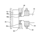
- a seal member 48 may be installed in the gap between the insertion hole 43 a of the brake housing 43 and the outer periphery of the shaft 10.
- a dust seal or an oil seal made of an elastic material such as a rubber material can be used as the seal member 48.
- the seal member 48 includes an annular body 48 a that is fixed to the inner peripheral surface of the insertion hole 43 a of the brake housing 43, and a hook-shaped contact piece 48 b that is formed on the inner periphery of the annular body 48 a and contacts the outer peripheral surface of the shaft 10. Have. Also in this case, the same effect as that of the above embodiment is obtained.
- the case where a part of the brake part 30 (the protruding part 36 of the yoke 32) overlaps the stator 2 in the radial direction is described as an example, but the present invention is not limited to this.
- the whole brake part 30 is provided inside the resin part 25, it is good also as a structure by which the whole brake part 30 overlaps with the stator 2 and is arrange
- the brake unit 30 is an electromagnetic brake
- the present invention is not limited to this.
- a brake driven by hydraulic pressure or air pressure may be used.
- the rotating electrical machine 1 includes the encoder unit 50
- the encoder unit 50 is not necessarily provided.
Landscapes
- Engineering & Computer Science (AREA)
- General Engineering & Computer Science (AREA)
- Power Engineering (AREA)
- Mechanical Engineering (AREA)
- Connection Of Motors, Electrical Generators, Mechanical Devices, And The Like (AREA)
- Braking Arrangements (AREA)
- Mounting Of Bearings Or Others (AREA)
- Rolling Contact Bearings (AREA)
Abstract
【課題】ブレーキを備えた回転電機を軸方向に薄型化できるようにする。 【解決手段】回転電機1は、電磁部20と、ブレーキ部30とを有する。電磁部20は、固定子2及び回転子3を備えており、シャフト10を回転するように構成される。ブレーキ部30は、シャフト10の制動を行うように構成される。このブレーキ部30は、電磁部20の反負荷側に位置し、少なくとも一部が電磁部20の固定子2と径方向に重なり合って配置される。
Description
開示の実施形態は、回転電機に関する。
特許文献1には、モータシャフトを備えた回転子及び固定子を有する回転電機と、モータシャフトの反負荷側に対し制動を行う電磁ブレーキ装置とが記載されている。
上記従来技術は、回転電機と電磁ブレーキ装置とが軸方向に並列に配置される構造であることから、軸方向寸法が大きくなる傾向にある。一方で、使用環境や搭載性等の観点から、軸方向寸法を小さく抑えたい場合がある。この場合には、装置構成のさらなる最適化が要望される。
本発明はこのような問題点に鑑みてなされたものであり、軸方向に薄型化することが可能なブレーキを備えた回転電機を提供することを目的とする。
上記課題を解決するため、本発明の一の観点によれば、固定子を備え、シャフトを回転するように構成された電磁部と、前記電磁部の軸方向一方側に位置し、少なくとも一部が前記固定子と径方向に重なり合って配置された、前記シャフトの制動を行うように構成されたブレーキ部と、を有する回転電機が適用される。
また、本発明の別の観点によれば、固定子を備え、シャフトを回転するように構成された電磁部と、前記シャフトの制動を行うように構成されたブレーキ部と、前記固定子と前記ブレーキ部の少なくとも一部が径方向に重なり合うように前記電磁部と前記ブレーキ部とを連結する手段と、を有する回転電機が適用される。
本発明によれば、ブレーキを備えた回転電機を軸方向に薄型化することができる。
以下、一実施の形態について図面を参照しつつ説明する。なお、以下において、回転電機等の構成の説明の便宜上、上下左右等の方向を適宜使用する場合があるが、回転電機等の各構成の位置関係を限定するものではない。
<回転電機の全体構成>
図1に示すように、回転電機1は、電磁部20と、ブレーキ部30と、エンコーダ部50とを有する。ブレーキ部30は電磁部20の反負荷側(軸方向一方側の一例。図1中左側)に配置され、エンコーダ部50はブレーキ部30のさらに反負荷側に配置される。なお、電磁部20、ブレーキ部30及びエンコーダ部50の配置は、上記に限定されるものではない。例えば、ブレーキ部30及びエンコーダ部50の少なくとも一方が電磁部20の負荷側(図1中右側)に配置されてもよい。但し、電磁部20とブレーキ部30とは、軸方向に隣接して配置される。また、回転電機1は、モータでも発電機でもよい。
図1に示すように、回転電機1は、電磁部20と、ブレーキ部30と、エンコーダ部50とを有する。ブレーキ部30は電磁部20の反負荷側(軸方向一方側の一例。図1中左側)に配置され、エンコーダ部50はブレーキ部30のさらに反負荷側に配置される。なお、電磁部20、ブレーキ部30及びエンコーダ部50の配置は、上記に限定されるものではない。例えば、ブレーキ部30及びエンコーダ部50の少なくとも一方が電磁部20の負荷側(図1中右側)に配置されてもよい。但し、電磁部20とブレーキ部30とは、軸方向に隣接して配置される。また、回転電機1は、モータでも発電機でもよい。
なお、本明細書において「負荷側」とは回転電機1に対してシャフト10が突出する方向(図1中右側)を指し、「反負荷側」とは負荷側の反対方向、すなわちこの例では回転電機1に対してエンコーダ部50が配置される方向(図1中左側)を指す。
<電磁部の構成>
電磁部20は、筒状のフレーム4の内側に設けられた固定子2と、シャフト10に設けられた回転子3とを備え、シャフト10を回転するように構成される。
電磁部20は、筒状のフレーム4の内側に設けられた固定子2と、シャフト10に設けられた回転子3とを備え、シャフト10を回転するように構成される。
固定子2は、フレーム4の内周面に設けられた環状の固定子鉄心21と、固定子鉄心21に周方向に配置された複数の固定子巻線23とを有する。固定子巻線23はボビン22に巻回され、そのボビン22が固定子鉄心21に装着されている。固定子2の反負荷側には、各固定子巻線23の巻き始め及び巻き終りの端末(図示せず)を結線処理するための結線部24が設けられている。
回転子3は、シャフト10の外周面に設けられる。回転子3は、固定子鉄心21と所定の磁気的ギャップを空けて配置された環状の回転子鉄心27と、回転子鉄心27の内部に配設された複数の永久磁石28とを備えている。なお、永久磁石28は、回転子鉄心27の外周面に設置されてもよい。複数の永久磁石28は、回転子鉄心27の外周部に形成する磁極が周方向にN極及びS極を交互に繰り返すように、回転子鉄心27に配置されている。
フレーム4の負荷側(図1中右側)には、負荷側ブラケット5が設けられている。負荷側ブラケット5には、負荷側軸受6が固定されている。負荷側ブラケット5の外周部は、複数のボルト14によってフレーム4に固定されている。また、ブレーキ部30のヨーク32(詳細は後述)の内周には、反負荷側軸受7(第1軸受の一例)が固定されている。ヨーク32の外周部(後述するフランジ部37)は、複数のボルト15によってフレーム4に固定されている。シャフト10は、負荷側軸受6及び反負荷側軸受7により回転自在に支持されている。
電磁部20は、固定子2を封止する樹脂部25を有している。樹脂部25は、固定子鉄心21、ボビン22、固定子巻線23、及び結線部24を含む固定子2の周囲を被覆する。
電磁部20では、図示しない外部電源から結線部24を介して固定子2の固定子巻線23に例えば交流電流が供給される。これにより、固定子巻線23が回転磁界を発生し、発生した回転磁界が回転子3の永久磁石28の界磁磁束と作用することで、回転子3に周方向の推力が発生し、シャフト10が回転する。
<エンコーダ部の構成>
エンコーダ部50は、エンコーダ12と、エンコーダ12を収容するエンコーダカバー45とを有する。エンコーダ12は、シャフト10の反負荷側(軸方向一方側の一例)の端部に配置され、シャフト10の回転位置を検出する。エンコーダ12は、磁気式又は光学式のいずれでもよく、あるいはその両方を含むものでもよい。エンコーダカバー45の外周部は、複数のボルト16によってブレーキハウジング43に固定されている。
エンコーダ部50は、エンコーダ12と、エンコーダ12を収容するエンコーダカバー45とを有する。エンコーダ12は、シャフト10の反負荷側(軸方向一方側の一例)の端部に配置され、シャフト10の回転位置を検出する。エンコーダ12は、磁気式又は光学式のいずれでもよく、あるいはその両方を含むものでもよい。エンコーダカバー45の外周部は、複数のボルト16によってブレーキハウジング43に固定されている。
<ブレーキ部の構成>
ブレーキ部30は、シャフト10の制動を行うように構成される。本実施形態では、ブレーキ部30は、電磁ブレーキ(この例では無励磁作動型ブレーキ)として構成されている。ブレーキ部30は、ブレーキコイル31と、フィールドコアであるヨーク32と、ブレーキディスク33と、アーマチュア34と、サイドプレート35とを有する。ブレーキディスク33、アーマチュア34、及びサイドプレート35は、ヨーク32とエンコーダ部50との間で、負荷側から反負荷側に向けてアーマチュア34、ブレーキディスク33、サイドプレート35の順に配置されている。
ブレーキ部30は、シャフト10の制動を行うように構成される。本実施形態では、ブレーキ部30は、電磁ブレーキ(この例では無励磁作動型ブレーキ)として構成されている。ブレーキ部30は、ブレーキコイル31と、フィールドコアであるヨーク32と、ブレーキディスク33と、アーマチュア34と、サイドプレート35とを有する。ブレーキディスク33、アーマチュア34、及びサイドプレート35は、ヨーク32とエンコーダ部50との間で、負荷側から反負荷側に向けてアーマチュア34、ブレーキディスク33、サイドプレート35の順に配置されている。
ブレーキ部30は、少なくとも一部が電磁部20の固定子2と径方向に重なり合って配置される。本実施形態では、ヨーク32の少なくとも一部が固定子2と径方向に重なり合って配置される。具体的には、ヨーク32は突出部36を有しており、この突出部36が上記樹脂部25の径方向内側に反負荷側から挿入されることで、突出部36が固定子2の径方向内側に重なり合って配置される。なお、樹脂部25と突出部36とは隙間無く凹凸嵌合してもよいし、若干の隙間を設けて凹凸嵌合させてもよい。突出部36は反負荷側に開口した環状の凹部36aを有しており、この凹部36aにブレーキコイル31が収容されている。
また、ヨーク32は、突出部36より径方向外側に向けて延設されたフランジ部37を有する。フランジ部37の外径はフレーム4及び樹脂部25と略等しく、その外周面は回転電機1の表面に露出されている。図1に示す例では、モータケーブル(図示せず)が接続されるコネクタ13が、樹脂部25の外周面とフランジ部37の外周面とに跨って設置されている。フランジ部37には、周方向に適宜の間隔で形成された複数のばね用凹部37aが形成されており、各ばね用凹部37aにコイルばね38が収納されている。コイルばね38は、アーマチュア34を反負荷側(ブレーキディスク33側)へ向けて付勢している。
ヨーク32の内周の開口32aには、反負荷側軸受7が固定されている。反負荷側軸受7は、開口32aに設けられた円環状の突起部材17及び板ばね18により位置決めされている。
ブレーキディスク33は、例えば円板状のディスクの両面に摩擦材を設けた構造である。ブレーキディスク33は、シャフト10の反負荷側に固定されたハブ39に軸方向のスプライン部が嵌合して、シャフト10に軸方向に移動可能かつ周方向に回転不能に設けられている。アーマチュア34は、適宜の磁性体材料(例えば鋼板)からなる例えば円板状の部材である。アーマチュア34は、ヨーク32に固定された円筒状のカラー40を外周部に挿通させて、軸方向に移動可能かつ周方向に回転不能に設けられている。サイドプレート35は、鉄、アルミ、複合炭素繊維材料等の適宜の材料からなる例えば円板状の部材である。サイドプレート35の外周部は、カラー40に挿通した複数の固定ボルト41によってヨーク32のフランジ部37に固定されている。ブレーキディスク33の径方向の寸法は、カラー40と接触しない範囲でなるべく大きくなるように設定されている。
また、ブレーキ部30は、ブレーキディスク33等を収容するブレーキハウジング43を有している。ブレーキハウジング43には、シャフト10の反負荷側(軸方向一方側の一例)の端部が挿通される挿通孔43aが形成されており、この挿通孔43aとシャフト10の外周との隙間に軸受44(第2軸受の一例)が設置されている。軸受44は、外輪がブレーキハウジング43に固定され、内輪がシャフト10に固定されており、ブレーキハウジング43内で発生したブレーキ粉のエンコーダ部50側への流入を防止するシール部材として機能する。なお、ブレーキハウジング43は図示しない固定ボルトによりヨーク32に固定される。
ブレーキ部30では、ブレーキコイル31が通電されると、アーマチュア34がコイルばね38の付勢力に抗してヨーク32に吸引されてブレーキディスク33から離れ、シャフト10の制動が解放される。一方、ブレーキコイル31への通電が停止されると、アーマチュア34がコイルばね38の付勢力により反負荷側に移動し、アーマチュア34とサイドプレート35との間でブレーキディスク33が挟まれ、シャフト10が制動される。
なお、上記ではブレーキ部30が無励磁作動形ブレーキである場合を一例として説明したが、これに限定されるものではなく、例えば励磁作動形ブレーキとしてもよい。
以上において、電磁部20の樹脂部25とブレーキ部30の突出部36との凹凸嵌合構造とボルト15とが、固定子とブレーキ部の少なくとも一部が径方向に重なり合うように電磁部とブレーキ部とを連結する手段の一例に相当する。
<実施形態の効果>
以上説明したように、本実施形態の回転電機1では、ブレーキ部30が電磁部20の反負荷側に位置する。このとき、ブレーキ部30の少なくとも一部が固定子2と径方向に重なり合って配置されるので、電磁部20とブレーキ部30とが軸方向に並列に(径方向に重なり合わずに)配置される場合に比べて回転電機1の軸方向寸法を低減できる。したがって、回転電機1を軸方向に薄型化できる。
以上説明したように、本実施形態の回転電機1では、ブレーキ部30が電磁部20の反負荷側に位置する。このとき、ブレーキ部30の少なくとも一部が固定子2と径方向に重なり合って配置されるので、電磁部20とブレーキ部30とが軸方向に並列に(径方向に重なり合わずに)配置される場合に比べて回転電機1の軸方向寸法を低減できる。したがって、回転電機1を軸方向に薄型化できる。
また、本実施形態では特に、ブレーキ部30は、ブレーキコイル31及びヨーク32を有し、ヨーク32の少なくとも一部が固定子2と径方向に重なり合って配置される。これにより、次の効果を奏する。すなわち、ブレーキ部30は、ブレーキコイル31及びヨーク32を有する電磁ブレーキである。ヨーク32の少なくとも一部を固定子2と径方向に重なり合うように配置させることにより、ブレーキディスク33については固定子2により径方向寸法を制限されない配置構成とすることができる。これにより、ブレーキディスク33の径方向寸法を大型化し、ブレーキ部30の制動機能を向上できる。
また、本実施形態では特に、電磁部20は、固定子2を封止する樹脂部25を有し、ヨーク32は、ブレーキコイル31が収容され樹脂部25の径方向内側に挿入される突出部36を有する。これにより、樹脂部25と反負荷側軸受7との間の空間にヨーク32及びブレーキコイル31を配置することが可能となり、当該空間を有効活用できる。また、回転電機1の組立時にヨーク32の突出部36と樹脂部25との凹凸嵌合により電磁部20とブレーキ部30との概略の位置決めをすることが可能となり、組立作業性を向上できる。
また、本実施形態では特に、ヨーク32は、突出部36より径方向外側に向けて延設され外周面が回転電機1の表面に露出するフランジ部37を有する。これにより、次の効果を奏する。すなわち、ブレーキディスク33は、カラー40と接触しないように径方向寸法が設定されるところ、本実施形態では、ヨーク32のフランジ部37の外周面が回転電機1の表面に露出するように構成されるので、ヨーク32がブレーキハウジング43の内部に収容される場合に比べて、ヨーク32の径方向寸法を増大できる。これにより、カラー40をより外周側の位置に設置することができるので、ブレーキディスク33を径方向にさらに大型化できる。その結果、コイルばね38及びブレーキコイル31の小型化が可能となるので、回転電機1の軸方向のさらなる薄型化が可能となる。
また、本実施形態では特に、ブレーキ部30は、ヨーク32の内周に固定されシャフト10を回転自在に支持する反負荷側軸受7を有する。これにより、ヨーク32が反負荷側軸受7を支持する軸受支持部材を兼ねることができ、別途、反負荷側ブラケット等の軸受支持部材を設置する必要がない。その結果、軸方向のさらなる薄型化、部品の削減、コスト低減が可能となる。
また、本実施形態では特に、ブレーキ部30の反負荷側に配置され、シャフト10の回転位置を検出するように構成されたエンコーダ12をさらに有し、ブレーキ部30は、ブレーキコイル31及びヨーク32とエンコーダ12との間に配置されたブレーキディスク33を有する。このような配置構成とすることにより、例えばブレーキディスク33がブレーキコイル31及びヨーク32と電磁部20との間に配置される場合に比べて、ブレーキコイル31及びヨーク32とエンコーダ12とを離間させることができる。これにより、エンコーダ12に対するブレーキ部30からの漏れ磁束の影響を低減できる。
また、本実施形態では特に、ブレーキ部30は、シャフト10の反負荷側の端部が挿通される挿通孔43aが形成された、ブレーキディスク33等を収容するブレーキハウジング43と、挿通孔43aとシャフト10の外周との隙間に設けられた軸受44とを有する。軸受44により、ブレーキハウジング43内で発生したブレーキ粉が挿通孔43aを介してエンコーダ12側に流入するのを防止できる。これにより、エンコーダ12の位置検出精度が低下するのを防止できる。
また、本実施形態では特に、上記ブレーキ粉のエンコーダ12側への流入を防止するシール部材として、外輪がブレーキハウジング43に固定され、内輪がシャフト10に固定された軸受44を用いることにより、次の効果を奏する。すなわち、シール部材として例えばダストシールやオイルシール等を用いる場合、シャフト10との摺動箇所にグリース等の潤滑剤が塗布されるので、その潤滑剤がエンコーダ12側に流入して検出精度を低下させるおそれがある。本実施形態では、シール部材として軸受44を用いることにより、潤滑剤を軸受44内に封入でき、潤滑剤がエンコーダ12側に流入するのを防止できる効果がある。
<変形例>
なお、開示の実施形態は、上記に限られるものではなく、その趣旨及び技術的思想を逸脱しない範囲内で種々の変形が可能である。
なお、開示の実施形態は、上記に限られるものではなく、その趣旨及び技術的思想を逸脱しない範囲内で種々の変形が可能である。
例えば、図2に示すように、ブレーキハウジング43の挿通孔43aとシャフト10の外周との隙間にシール部材48を設置してもよい。シール部材48としては、ゴム材等の弾性材料からなるダストシールやオイルシール等を用いることができる。シール部材48は、ブレーキハウジング43の挿通孔43aの内周面に固定される環状体48aと、環状体48aの内周に形成されシャフト10の外周面と接触する鉤状の接触片48bとを有する。この場合にも、上記実施形態と同様の効果を得る。
また、以上では、ブレーキ部30の一部(ヨーク32の突出部36)が固定子2と径方向に重なり合う場合を一例として説明したが、これに限定されるものではない。例えば、ブレーキ部30全体が樹脂部25の内側に設けられる場合等、ブレーキ部30の全部が固定子2と径方向に重なり合って配置された構成としてもよい。
また、以上では、ブレーキ部30が電磁ブレーキである場合を一例として説明したが、これに限定されるものではなく、例えば油圧や空気圧等により駆動されるブレーキとしてもよい。
また、以上では、回転電機1がエンコーダ部50を有する場合を一例として説明したが、エンコーダ部50は必ずしも設けなくともよい。
また、以上既に述べた以外にも、上記実施形態による手法を適宜組み合わせて利用しても良い。その他、一々例示はしないが、上記実施形態は、その趣旨を逸脱しない範囲内において、種々の変更が加えられて実施されるものである。
1 回転電機
2 固定子
7 反負荷側軸受(第1軸受の一例)
10 シャフト
12 エンコーダ
20 電磁部
25 樹脂部
30 ブレーキ部
31 ブレーキコイル
32 ヨーク
33 ブレーキディスク
36 突出部
37 フランジ部
43 ブレーキハウジング
43a 挿通孔
44 軸受(シール部材の一例、第2軸受の一例)
48 シール部材
2 固定子
7 反負荷側軸受(第1軸受の一例)
10 シャフト
12 エンコーダ
20 電磁部
25 樹脂部
30 ブレーキ部
31 ブレーキコイル
32 ヨーク
33 ブレーキディスク
36 突出部
37 フランジ部
43 ブレーキハウジング
43a 挿通孔
44 軸受(シール部材の一例、第2軸受の一例)
48 シール部材
Claims (8)
- 固定子を備え、シャフトを回転するように構成された電磁部と、
前記電磁部の軸方向一方側に位置し、少なくとも一部が前記固定子と径方向に重なり合って配置された、前記シャフトの制動を行うように構成されたブレーキ部と、
を有することを特徴とする回転電機。 - 前記ブレーキ部は、
ブレーキコイル及びヨークを有し、
前記ヨークの少なくとも一部が前記固定子と径方向に重なり合って配置される
ことを特徴とする請求項1に記載の回転電機。 - 前記電磁部は、
前記固定子を封止する樹脂部を有し、
前記ヨークは、
前記ブレーキコイルが収容され前記樹脂部の径方向内側に挿入される突出部を有する
ことを特徴とする請求項2に記載の回転電機。 - 前記ヨークは、
前記突出部より径方向外側に向けて延設され外周面が前記回転電機の表面に露出するフランジ部を有する
ことを特徴とする請求項3に記載の回転電機。 - 前記ブレーキ部は、
前記ヨークの内周に固定され前記シャフトを回転自在に支持する第1軸受を有する
ことを特徴とする請求項2乃至4のいずれか1項に記載の回転電機。 - 前記ブレーキ部の軸方向一方側に配置され、前記シャフトの回転位置を検出するように構成されたエンコーダをさらに有し、
前記ブレーキ部は、
前記ブレーキコイル及び前記ヨークと前記エンコーダとの間に配置されたブレーキディスクを有する
ことを特徴とする請求項2乃至5のいずれか1項に記載の回転電機。 - 前記ブレーキ部は、
前記シャフトの軸方向一方側の端部が挿通される挿通孔が形成された、前記ブレーキディスクを収容するブレーキハウジングと、
前記挿通孔と前記シャフトの外周との隙間に設けられたシール部材と、を有する
ことを特徴とする請求項6に記載の回転電機。 - 前記シール部材は、
外輪が前記ブレーキハウジングに固定され、内輪が前記シャフトに固定された第2軸受である
ことを特徴とする請求項7に記載の回転電機。
Priority Applications (3)
| Application Number | Priority Date | Filing Date | Title |
|---|---|---|---|
| JP2016523020A JPWO2015181900A1 (ja) | 2014-05-27 | 2014-05-27 | 回転電機 |
| PCT/JP2014/064034 WO2015181900A1 (ja) | 2014-05-27 | 2014-05-27 | 回転電機 |
| CN201480078353.1A CN106233587A (zh) | 2014-05-27 | 2014-05-27 | 旋转电机 |
Applications Claiming Priority (1)
| Application Number | Priority Date | Filing Date | Title |
|---|---|---|---|
| PCT/JP2014/064034 WO2015181900A1 (ja) | 2014-05-27 | 2014-05-27 | 回転電機 |
Publications (1)
| Publication Number | Publication Date |
|---|---|
| WO2015181900A1 true WO2015181900A1 (ja) | 2015-12-03 |
Family
ID=54698284
Family Applications (1)
| Application Number | Title | Priority Date | Filing Date |
|---|---|---|---|
| PCT/JP2014/064034 Ceased WO2015181900A1 (ja) | 2014-05-27 | 2014-05-27 | 回転電機 |
Country Status (3)
| Country | Link |
|---|---|
| JP (1) | JPWO2015181900A1 (ja) |
| CN (1) | CN106233587A (ja) |
| WO (1) | WO2015181900A1 (ja) |
Cited By (7)
| Publication number | Priority date | Publication date | Assignee | Title |
|---|---|---|---|---|
| CN107042419A (zh) * | 2016-01-28 | 2017-08-15 | 至禾机器工业有限公司 | 加工机的驱动装置及其销售和装配方法 |
| CN107303235A (zh) * | 2016-04-19 | 2017-10-31 | 李书贤 | 助行器的模块化电动轮组 |
| CN107872116A (zh) * | 2016-09-26 | 2018-04-03 | 日本电产三协株式会社 | 带制动器的电动机 |
| WO2019082490A1 (ja) * | 2017-10-24 | 2019-05-02 | ミネベアミツミ株式会社 | 回転装置 |
| JP2020513723A (ja) * | 2016-12-01 | 2020-05-14 | イエフペ エネルジ ヌヴェルIfp Energies Nouvelles | 磁気位置センサを含む回転電気機械 |
| JPWO2022153438A1 (ja) * | 2021-01-14 | 2022-07-21 | ||
| WO2025104840A1 (ja) * | 2023-11-15 | 2025-05-22 | ファナック株式会社 | ブレーキを有するモータ |
Families Citing this family (3)
| Publication number | Priority date | Publication date | Assignee | Title |
|---|---|---|---|---|
| CN109194079A (zh) * | 2018-10-15 | 2019-01-11 | 广州数控设备有限公司 | 一种交流永磁同步电动机及其制造方法 |
| DE102019120250A1 (de) * | 2019-07-26 | 2021-01-28 | Dunkermotoren Gmbh | Bremse für einen Elektromotor und Herstellungsverfahren hierfür |
| CN116641974A (zh) * | 2023-05-09 | 2023-08-25 | 成都超德创科技有限公司 | 一种失电式回转制动器 |
Citations (7)
| Publication number | Priority date | Publication date | Assignee | Title |
|---|---|---|---|---|
| JPS5833950A (ja) * | 1981-08-19 | 1983-02-28 | Fuji Electric Co Ltd | 電動機 |
| JPS6110941A (ja) * | 1984-06-27 | 1986-01-18 | Hitachi Ltd | デイスクブレ−キの手動緩め装置 |
| JPH0561555U (ja) * | 1992-01-29 | 1993-08-13 | オリエンタルモーター株式会社 | 電動機用直交軸減速機 |
| JP2007195342A (ja) * | 2006-01-19 | 2007-08-02 | Toshiba Corp | ブレーキ付きモータおよびそのモータを用いたエレベータ駆動システム |
| JP2009131148A (ja) * | 2007-11-19 | 2009-06-11 | Siemens Ag | ロータに直接磁気ブレーキを設けた電気機械 |
| JP2011190918A (ja) * | 2010-03-17 | 2011-09-29 | Yaskawa Electric Corp | ブレーキ装置及び回転電機 |
| JP2013059169A (ja) * | 2011-09-07 | 2013-03-28 | Yaskawa Electric Corp | 回転電機 |
Family Cites Families (1)
| Publication number | Priority date | Publication date | Assignee | Title |
|---|---|---|---|---|
| JP4775551B2 (ja) * | 2005-11-16 | 2011-09-21 | 株式会社安川電機 | ブレーキ付モータ |
-
2014
- 2014-05-27 WO PCT/JP2014/064034 patent/WO2015181900A1/ja not_active Ceased
- 2014-05-27 JP JP2016523020A patent/JPWO2015181900A1/ja active Pending
- 2014-05-27 CN CN201480078353.1A patent/CN106233587A/zh active Pending
Patent Citations (7)
| Publication number | Priority date | Publication date | Assignee | Title |
|---|---|---|---|---|
| JPS5833950A (ja) * | 1981-08-19 | 1983-02-28 | Fuji Electric Co Ltd | 電動機 |
| JPS6110941A (ja) * | 1984-06-27 | 1986-01-18 | Hitachi Ltd | デイスクブレ−キの手動緩め装置 |
| JPH0561555U (ja) * | 1992-01-29 | 1993-08-13 | オリエンタルモーター株式会社 | 電動機用直交軸減速機 |
| JP2007195342A (ja) * | 2006-01-19 | 2007-08-02 | Toshiba Corp | ブレーキ付きモータおよびそのモータを用いたエレベータ駆動システム |
| JP2009131148A (ja) * | 2007-11-19 | 2009-06-11 | Siemens Ag | ロータに直接磁気ブレーキを設けた電気機械 |
| JP2011190918A (ja) * | 2010-03-17 | 2011-09-29 | Yaskawa Electric Corp | ブレーキ装置及び回転電機 |
| JP2013059169A (ja) * | 2011-09-07 | 2013-03-28 | Yaskawa Electric Corp | 回転電機 |
Cited By (15)
| Publication number | Priority date | Publication date | Assignee | Title |
|---|---|---|---|---|
| CN107042419A (zh) * | 2016-01-28 | 2017-08-15 | 至禾机器工业有限公司 | 加工机的驱动装置及其销售和装配方法 |
| CN107303235A (zh) * | 2016-04-19 | 2017-10-31 | 李书贤 | 助行器的模块化电动轮组 |
| CN107872116A (zh) * | 2016-09-26 | 2018-04-03 | 日本电产三协株式会社 | 带制动器的电动机 |
| JP2020513723A (ja) * | 2016-12-01 | 2020-05-14 | イエフペ エネルジ ヌヴェルIfp Energies Nouvelles | 磁気位置センサを含む回転電気機械 |
| JP7162590B2 (ja) | 2016-12-01 | 2022-10-28 | イエフペ エネルジ ヌヴェル | 磁気位置センサを含む回転電気機械 |
| CN111279591A (zh) * | 2017-10-24 | 2020-06-12 | 美蓓亚三美株式会社 | 旋转装置 |
| JP2019080421A (ja) * | 2017-10-24 | 2019-05-23 | ミネベアミツミ株式会社 | 回転装置 |
| US11239730B2 (en) | 2017-10-24 | 2022-02-01 | Minebea Mitsumi Inc. | Rotating device |
| WO2019082490A1 (ja) * | 2017-10-24 | 2019-05-02 | ミネベアミツミ株式会社 | 回転装置 |
| JPWO2022153438A1 (ja) * | 2021-01-14 | 2022-07-21 | ||
| WO2022153438A1 (ja) * | 2021-01-14 | 2022-07-21 | 三菱電機株式会社 | 回転機 |
| DE112021006808T5 (de) | 2021-01-14 | 2023-11-02 | Mitsubishi Electric Corporation | Rotator |
| JP7415050B2 (ja) | 2021-01-14 | 2024-01-16 | 三菱電機株式会社 | 回転機 |
| US12500478B2 (en) | 2021-01-14 | 2025-12-16 | Mitsubishi Electric Corporation | Rotator |
| WO2025104840A1 (ja) * | 2023-11-15 | 2025-05-22 | ファナック株式会社 | ブレーキを有するモータ |
Also Published As
| Publication number | Publication date |
|---|---|
| JPWO2015181900A1 (ja) | 2017-04-20 |
| CN106233587A (zh) | 2016-12-14 |
Similar Documents
| Publication | Publication Date | Title |
|---|---|---|
| WO2015181900A1 (ja) | 回転電機 | |
| JP5936425B2 (ja) | ブレーキ付きモータ | |
| JP5943694B2 (ja) | ブレーキ付きモータ | |
| EP2190104A1 (en) | Hollow actuator | |
| KR101477905B1 (ko) | 회전 전기 기계 | |
| JP5705259B2 (ja) | 回転電機のステータコア固定構造 | |
| WO2013084270A1 (ja) | 電動機 | |
| CN108231325B (zh) | 一种旋转电磁铁 | |
| JP5631133B2 (ja) | 回転電機用ロータにおける金属管のロータコアへの固定方法 | |
| JP5445546B2 (ja) | 回転電機 | |
| WO2015068846A1 (ja) | 回転電機 | |
| JP6145391B2 (ja) | 駆動装置 | |
| JP6413747B2 (ja) | 回転電機 | |
| WO2017221843A1 (ja) | 電動式直動アクチュエータ | |
| JP6964135B2 (ja) | 電動機及び電動機の組立方法 | |
| EP4084295B1 (en) | Rotary electric machine | |
| JP2012080615A (ja) | 可変磁束モータ | |
| JP5860724B2 (ja) | アウターロータ型ブラシレスモータ | |
| JP2014180107A (ja) | 回転電機 | |
| WO2015092887A1 (ja) | ブレーキ付きモータ | |
| CN203813638U (zh) | 旋转电机 | |
| JP2012080616A (ja) | 可変磁束モータ | |
| JP2013201844A (ja) | 回転電機 | |
| JP2017229162A (ja) | 回転電動機、及び回転電動機の組み立て方法 | |
| JP5643038B2 (ja) | 回転電機用ロータ |
Legal Events
| Date | Code | Title | Description |
|---|---|---|---|
| 121 | Ep: the epo has been informed by wipo that ep was designated in this application |
Ref document number: 14893404 Country of ref document: EP Kind code of ref document: A1 |
|
| ENP | Entry into the national phase |
Ref document number: 2016523020 Country of ref document: JP Kind code of ref document: A |
|
| NENP | Non-entry into the national phase |
Ref country code: DE |
|
| 122 | Ep: pct application non-entry in european phase |
Ref document number: 14893404 Country of ref document: EP Kind code of ref document: A1 |