WO2015178286A1 - 緩衝器 - Google Patents
緩衝器 Download PDFInfo
- Publication number
- WO2015178286A1 WO2015178286A1 PCT/JP2015/063930 JP2015063930W WO2015178286A1 WO 2015178286 A1 WO2015178286 A1 WO 2015178286A1 JP 2015063930 W JP2015063930 W JP 2015063930W WO 2015178286 A1 WO2015178286 A1 WO 2015178286A1
- Authority
- WO
- WIPO (PCT)
- Prior art keywords
- seal
- rod guide
- outer peripheral
- shock absorber
- rod
- Prior art date
Links
Images


Classifications
-
- F—MECHANICAL ENGINEERING; LIGHTING; HEATING; WEAPONS; BLASTING
- F16—ENGINEERING ELEMENTS AND UNITS; GENERAL MEASURES FOR PRODUCING AND MAINTAINING EFFECTIVE FUNCTIONING OF MACHINES OR INSTALLATIONS; THERMAL INSULATION IN GENERAL
- F16F—SPRINGS; SHOCK-ABSORBERS; MEANS FOR DAMPING VIBRATION
- F16F9/00—Springs, vibration-dampers, shock-absorbers, or similarly-constructed movement-dampers using a fluid or the equivalent as damping medium
- F16F9/32—Details
- F16F9/36—Special sealings, including sealings or guides for piston-rods
- F16F9/362—Combination of sealing and guide arrangements for piston rods
-
- F—MECHANICAL ENGINEERING; LIGHTING; HEATING; WEAPONS; BLASTING
- F16—ENGINEERING ELEMENTS AND UNITS; GENERAL MEASURES FOR PRODUCING AND MAINTAINING EFFECTIVE FUNCTIONING OF MACHINES OR INSTALLATIONS; THERMAL INSULATION IN GENERAL
- F16F—SPRINGS; SHOCK-ABSORBERS; MEANS FOR DAMPING VIBRATION
- F16F9/00—Springs, vibration-dampers, shock-absorbers, or similarly-constructed movement-dampers using a fluid or the equivalent as damping medium
- F16F9/32—Details
-
- F—MECHANICAL ENGINEERING; LIGHTING; HEATING; WEAPONS; BLASTING
- F16—ENGINEERING ELEMENTS AND UNITS; GENERAL MEASURES FOR PRODUCING AND MAINTAINING EFFECTIVE FUNCTIONING OF MACHINES OR INSTALLATIONS; THERMAL INSULATION IN GENERAL
- F16F—SPRINGS; SHOCK-ABSORBERS; MEANS FOR DAMPING VIBRATION
- F16F9/00—Springs, vibration-dampers, shock-absorbers, or similarly-constructed movement-dampers using a fluid or the equivalent as damping medium
- F16F9/06—Springs, vibration-dampers, shock-absorbers, or similarly-constructed movement-dampers using a fluid or the equivalent as damping medium using both gas and liquid
- F16F9/061—Mono-tubular units
Definitions
- This invention relates to a shock absorber.
- FIG. 3 The shock absorber disclosed in FIG. 3 includes a cylinder in which a working chamber is formed, an annular rod guide that is fixed to the upper opening of the cylinder, and a rod that is inserted inside the rod guide so as to be movable in the axial direction. And an annular oil seal attached to the lower side of the rod guide and an annular outer seal fitted in an annular groove formed on the outer periphery of the rod guide. Then, the outer periphery of the rod is sealed with an oil seal, and the gap between the rod guide and the cylinder is sealed with an outer periphery seal to prevent the fluid in the working chamber from leaking to the outside air side.
- the oil seal is arranged on the lower side, which is the working chamber side of the rod guide, it is difficult for foreign matter on the outside air to reach the oil seal, and the oil seal can be prevented from being damaged.
- a dust seal for preventing foreign matters from being mixed is attached to the upper side of the rod guide, the number of parts increases and the assembly work becomes complicated.
- an annular groove having a U-shaped cross-section must be formed on the outer periphery of the rod guide in order to attach the outer periphery seal, and the shape of the rod guide is complicated and the processing cost of the rod guide is high. Become.
- the object of the present invention is to provide an oil seal on the working chamber side of the rod guide, provide a dust seal on the reaction chamber side of the rod guide, and further simplify the assembly work even when provided with an outer peripheral seal, It is an object of the present invention to provide a shock absorber capable of reducing the processing cost of the rod guide.
- a shock absorber includes a cylindrical member in which a working chamber is formed, an annular rod guide fixed to an opening on one side of the cylindrical member, and an axial movement inside the rod guide.
- a rod inserted into the rod guide, an oil seal that is attached to the rod guide working chamber side and seals the outer periphery of the rod, and a seal member that is stacked on the reaction chamber side of the rod guide.
- a dust seal that seals between the cylinder and the rod guide, and an outer peripheral seal that seals between the cylinder and the rod guide.
- FIG. 1 is a front view of a shock absorber according to an embodiment of the present invention, partially cut away.
- FIG. 2 is an enlarged view of the main part of FIG.
- FIG. 3A is a partially enlarged view of the longitudinal section of the seal member of the shock absorber according to the embodiment of the present invention.
- FIG. 3B is an end view of the cut portion showing a part of FIG. 3A in an enlarged manner.
- FIG. 4 is an explanatory view showing a state in which a part of FIG. 2 is enlarged and the hydraulic oil is going to move outward from between the rod guide and the cylinder.
- FIG. 5 is a longitudinal sectional view showing a modified example of the shock absorber according to the embodiment of the present invention and enlarging the changed part.
- the shock absorber A includes a cylinder (cylindrical member) 1 in which a working chamber L is formed, and an annular rod fixed to one side opening of the cylinder 1.
- a guide 2 a rod 4 that is inserted inside the rod guide 2 so as to be movable in the axial direction, an oil seal 10 that is attached to the working chamber L side of the rod guide 2 and seals the outer periphery of the rod 4, and the rod guide 2
- the seal member 11 includes a dust seal 7 that seals the outer periphery of the rod 4 and an outer periphery seal 8 that seals between the cylinder 1 and the rod guide 2.
- the shock absorber A according to the present embodiment will be described below in detail.
- the shock absorber A according to this embodiment is used in a vehicle such as an automobile.
- the cylinder 1 is connected to the wheel side, and the protruding end portion of the rod 4 protruding from the cylinder 1 is a vehicle body. It is connected to the side and set upright. For this reason, when an impact caused by road surface unevenness is input to the wheel, the rod 4 enters and exits the cylinder 1 and the shock absorber A expands and contracts.
- the shock absorber A may be used for vehicles other than automobiles, devices, structures, etc., and the cylinder 1 is connected to the vehicle body side and the rod 4 is connected to the wheel side so as to be set upside down. May be.
- a shock absorber A includes a cylinder 1 formed in a bottomed cylindrical shape, an annular rod guide 2 fixed to the upper opening of the cylinder 1, and a rod guide 2.
- a rod 4 that penetrates into and out of the cylinder 1, a piston 5 that is held at the lower end of the rod 4 and slidably contacts the inner peripheral surface of the cylinder 1, and a free piston 6 that slidably contacts the inner peripheral surface of the cylinder 1 on the opposite rod side
- the rebound member 3 which relieves the impact at the time of the maximum expansion
- the cylinder 1 there are formed a working chamber L that is filled with hydraulic oil, and an air chamber G that is partitioned by the working chamber L and the free piston 6 and in which gas is enclosed.
- the air chamber G expands and contracts due to the movement of the free piston 6 in the axial direction (up and down), and compensates for the change in the volume of the hydraulic oil due to the change in the cylinder volume and the temperature change due to the expansion and contraction operation of the shock absorber A. it can.
- the free piston 6 moves upward and the air chamber G expands, so that an increase in the cylinder internal volume corresponding to the rod retracting volume can be compensated by the air chamber G. .
- the free piston 6 moves downward and the air chamber G is reduced.
- the free piston 6 moves downward and the air chamber G is reduced.
- the free piston 6 moves upward and the air chamber G expands.
- the shock absorber A is provided with an air chamber G and is set to a single cylinder type.
- a reservoir is provided outside the cylinder 1 to enclose hydraulic oil and gas.
- the reservoir may compensate for changes in the cylinder volume and hydraulic oil volume.
- an outer cylinder is provided on the outer periphery of the cylinder 1, the shock absorber A is set to a double cylinder type, and a reservoir is formed between the cylinder 1 and the outer cylinder.
- the outer peripheral seal 8 may seal between the outer cylinder and the rod guide 2.
- the liquid with which the working chamber L is filled may be other than hydraulic oil, and can be appropriately changed as long as a damping force can be generated.
- the working chamber L is divided by the piston 5 into an extension side chamber L1 on the rod 4 side and a pressure side chamber L2 on the piston 5 side.
- the piston 5 is formed with an extension side passage 5a and a pressure side passage 5b communicating with the extension side chamber L1 and the pressure side chamber L2.
- a leaf valve 50 that opens and closes the extension side passage 5 a is stacked below the piston 5, and a leaf valve 51 that opens and closes the pressure side passage 5 b is stacked above the piston 5.
- the lower leaf valve 50 functions as an extension-side damping valve that opens the extension-side passage 5a only during the extension operation of the shock absorber A and provides resistance to the flow of hydraulic oil passing through the extension-side passage 5a.
- the upper leaf valve 51 functions as a pressure-side damping valve that opens the pressure-side passage 5b only during the compression operation of the shock absorber A and provides resistance to the flow of hydraulic oil that passes through the pressure-side passage 5b.
- the hydraulic oil in the expansion side chamber L1 to be reduced opens the lower leaf valve 50 and moves to the pressure side chamber L2 that expands through the expansion side passage 5a.
- the shock absorber A generates an extension side damping force due to the resistance of the leaf valve 50 when the hydraulic oil passes through the extension side passage 5a.
- the hydraulic oil in the pressure side chamber L2 to be reduced opens the upper leaf valve 51 and moves to the expansion side chamber L1 that expands through the pressure side passage 5b.
- the pressure side damping force is generated due to the resistance of the leaf valve 51 when the hydraulic oil passes through the pressure side passage 5b.
- the shock absorber A is set so as to generate an extension-side and compression-side damping force due to the resistance of the leaf valves 50 and 51.
- the configuration for imparting resistance to the flow of hydraulic oil that moves between the extension side chamber L1 and the compression side chamber L2 can be changed as appropriate.
- a poppet valve or an orifice may be substituted for the leaf valves 50 and 51.
- the damping force on the extension side and the compression side can be set individually.
- the rod 4 connected to the piston 5 includes a small-diameter mounting portion 4 a that holds the piston 5 on the outer periphery, and a shaft portion 4 b that extends upward from the mounting portion 4 a and penetrates the extension side chamber L 1 and protrudes outside the cylinder 1.
- An annular groove 4c extending in the circumferential direction is formed on the outer periphery of the shaft portion 4b disposed in the cylinder 1, and the rebound member 3 is attached together with a later-described seat 30 by an annular stopper 32 fitted into the groove 4c.
- An annular rebound cushion 31 is supported.
- the rebound cushion 31 is made of an elastic body such as rubber, and abuts against the seat 30 when the shock absorber A is fully extended, elastically deforms, and relieves impact at the time of maximum extension.
- the shaft portion 4 b of the rod 4 passes through the annular rod guide 2 fixed to the upper opening of the cylinder 1.
- the rod guide 2 has an annular body portion 2a, an annular case portion 2b connected to the lower side of the body portion 2a, and an arc shape projecting from the inner periphery of the lower end portion of the case portion 2b to the center side. And claw 2c.
- the shape of the upper part of the main body 2a is substantially a truncated cone.
- An inclined surface 2d is formed on the upper portion of the main body 2a so as to be inclined so that the outer circumference is gradually reduced in diameter toward the upper end.
- the shape of the lower part of case part 2b is an inverted truncated cone shape.
- an inclined surface 2e is formed so that the outer periphery is gradually reduced in diameter toward the lower end, and is opposite to the inclined surface 2d.
- a bottom groove 2f extending in the radial direction from the outer peripheral end to the inner peripheral end is formed in the lower portion of the case portion 2b, and the bottom groove 2f opens in a gap between the claws 2c.
- a seal member 11 that seals the outer periphery of the rod 4 and the inner periphery of the cylinder 1 is stacked on the upper side of the main body 2a of the rod guide 2.
- the rod 4 is axially movable on the inner periphery of the main body 2a.
- a supporting annular bearing 12 is fitted.
- An oil seal 10 that seals the outer periphery of the rod 4 and a seal holder 13 are held on the inner periphery of the case portion 2b, and an annular sheet 30 is stacked below the case portion 2b.
- Both the oil seal 10 and the seal holder 13 are made of an elastic body such as rubber, and after the oil seal 10 is inserted inside the case portion 2b, the seal holder 13 is elastically deformed and fitted into the upper side of the claw 2c. Thus, the oil seal 10 and the seal holder 13 are prevented from coming off by the claw 2c. Further, since the bearing 12 is fitted to the main body 2a and is held by the main body 2a, the rod guide 2, the bearing 12, the oil seal 10 and the seal holder 13 are assembled in advance to constitute the rod guide assembly B. The cylinder 1 can be assembled in an integrated state.
- a groove 1a along the circumferential direction is formed on the inner periphery of the cylinder 1, and a retaining ring 14 is fitted in the groove 1a. Then, the seat 30, the rod guide assembly B, and the seal member 11 are laminated in this order on the upper side of the retaining ring 14 protruding from the inner peripheral surface of the cylinder 1, and the upper end 1 b of the cylinder 1 is crimped inward to 30, the rod guide assembly B and the seal member 11 are stacked and fixed to the upper opening of the cylinder 1.
- the assembling work can be simplified as compared with the case where they are individually assembled to the cylinder 1. .
- seat 30, the rod guide assembly B, and the sealing member 11 can be changed suitably.
- a portion corresponding to the groove 1a may be protruded to the inner peripheral side by roll caulking, and the sheet 30 may be hooked on the protruding portion.
- the oil seal 10 is separated from a dust seal 7 described later, and is disposed closer to the working chamber L than the bearing 12.
- the oil seal 10 can be separated from the foreign matter on the outside air side, and even if the foreign matter passes through the dust seal 7, the movement of the foreign matter to the working chamber L side can also be suppressed by the bearing 12. It is difficult to reach 10 and the damage of the oil seal 10 due to foreign matter can be suppressed, and the durability of the oil seal 10 can be improved.
- the oil seal 10 is in sliding contact with the outer peripheral surface of the portion of the rod 4 sandwiched between the piston 5 and the bearing 12.
- This portion is a portion that is difficult to bend even if an external force is applied laterally to the rod 4, so that the lip portion 10 a of the oil seal 10 is difficult to separate from the outer peripheral surface of the rod 4, and the sealing performance of the oil seal 10 is improved. it can. Furthermore, since the oil seal 10 and the dust seal 7 are separated and separated, it is easy to select an optimal material for each of them when forming them.
- the annular sheet 30 laminated on the lower side of the case part 2 b has the shaft part 4 b of the rod 4 inserted inside, and constitutes the rebound member 3 together with the rebound cushion 31.
- the seat 30 includes an annular plate-like abutting portion 30a against which the rebound cushion 31 abuts and an annular plate-shaped seat portion 30b provided on the outer peripheral side of the abutting portion 30a.
- a plurality of notches 30e are formed in the circumferential direction on the outer peripheral portion of the seat portion 30b, and a hooking groove 30f that is hooked on the retaining ring 14 is formed in the lower portion.
- the notch 30e faces the inclined surface 2e formed on the outer periphery of the lower portion of the case portion 2b, and the vertical passage 33 formed between the notch 30e and the cylinder 1 and between the inclined surface 2e and the cylinder 1 are provided.
- the annular passage 20 formed, the lateral passage 21 formed between the bottom groove 2f and the seat portion 30b of the seat 30, and a gap (not shown) between the claws 2c constitute a communication passage P.
- the communication path P communicates the working chamber L and the gap S formed between the seal holder 13 and the abutting portion 30 a of the seat 30 to transmit the pressure in the working chamber L to the oil seal 10.
- the gap S formed between the seal holder 13 and the sheet 30 and the working chamber L communicate with each other by the communication path P, when the working chamber L is pressurized while being sealed in the gas chamber G while being compressed, the gap S is also pressurized, and the seal holder 13 is compressed by this pressure.
- the compression reduces the diameter of the support portion 13b of the seal holder 13 and increases the force for tightening the lip portion 10a of the oil seal 10. That is, by applying the pressure in the working chamber L to the oil seal 10 via the communication path P, the gap S and the seal holder 13, the force for pressing the lip portion 10 a of the oil seal 10 against the outer peripheral surface of the rod 4 is increased.
- the sealing performance of the oil seal 10 can be improved.
- the rebound cushion 31 collides with the abutting portion 30a of the seat 30 and does not overlap the notch 30e that is the opening of the communication path P on the working chamber L side. For this reason, the rebound cushion 31 is not damaged by the edge of the notch 30e, and the durability of the rebound cushion 31 can be enhanced even when the communication path P passes through the seat 30. Further, since the communication passage P is configured to include the annular passage 20, it is not necessary to align the bottom groove 2f and the notch 30e, and the assembling property of the shock absorber A can be improved.
- the configuration of the communication path P can be changed as appropriate.
- the bottom groove 2f and the gap between the claws 2c arranged on the same straight line are arranged at equal intervals in the circumferential direction, and the seal holder 13 is arranged.
- the pressure may be uniformly applied to the surface.
- the shape, number, and arrangement of the claws 2c can be changed as appropriate.
- the claw 2c may be formed in an annular shape, and the bottom groove 2f may be extended to the inner peripheral end of the claw 2c.
- the seal member 11 laminated on the upper side of the main body 2a is composed of a metal ring-plate-like insert member 9 and a rubber member 71 that covers the insert member 9.
- the rubber member 71 includes an annular dust seal 7 that extends while tilting upward from the inner peripheral portion of the insert member 9, an annular outer peripheral seal 8 that extends downward from the outer peripheral portion of the insert member 9, and the insert member 9.
- a connecting rubber portion 70 that covers the lower surface and connects the dust seal 7 and the outer peripheral seal 8.
- the dust seal 7 is in sliding contact with the outer peripheral surface of the shaft portion 4 b of the rod 4 and seals the outer periphery of the rod 4 to prevent foreign matter from entering the cylinder 1 from the outside air side.
- the outer peripheral seal 8 is in close contact with the upper inclined surface 2d of the rod guide 2 and the inner peripheral surface of the cylinder 1, and prevents the hydraulic oil in the cylinder 1 from leaking to the outside air side.
- the connecting rubber portion 70 is in close contact with the upper side surface of the rod guide 2.
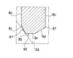
- the outer peripheral seal 8 is lowered while gradually expanding from the lower end of the inner peripheral surface 8a and the annular inner peripheral surface 8a and outer peripheral surface 8b that are substantially perpendicular to the insert member 9.
- An annular first inclined surface 8c extending to the side
- an annular second inclined surface 8d extending downward while gradually reducing the diameter from the lower end of the outer peripheral surface 8b, and lower ends of the first inclined surface 8c and the second inclined surface 8d
- an annular bottom surface 8e The corner portion formed at the boundary portion between the first inclined surface 8c and the bottom surface 8e is the inner peripheral lip 80
- the corner portion formed at the boundary portion between the outer peripheral surface 8b and the second inclined surface 8d is the outer peripheral lip 81.
- the outer peripheral lip 81 is provided above the inner peripheral lip 80.
- the seal member 11 when the seal member 11 is inserted into the cylinder 1 along the axial direction of the cylinder 1 and the inner peripheral lip 80 contacts the inclined surface 2d on the upper side of the rod guide 2, the inclined surface 2d and the first inclined surface
- the angle ⁇ 1 formed by the surface 8c is set to be smaller than the angle ⁇ 2 formed by the upper inclined surface 2d of the rod guide 2 and the bottom surface 8e ( ⁇ 1> ⁇ 2).
- the volume of the outer peripheral seal 8 is set so as to occupy most of the volume of the accommodating portion surrounded by the inclined surface 2 d of the rod guide 2, the inner peripheral surface of the cylinder 1 and the insert member 9.
- the configuration of the seal member 11 includes a dust seal 7 and an outer peripheral seal 8, and is set so that the outer periphery of the rod 4 can be sealed with the dust seal 7 and the rod guide 2 and the cylinder 1 can be sealed with the outer peripheral seal 8. As long as it is done, it can be changed as appropriate.
- the inner peripheral lip 80 disposed on the lower side is formed on the inclined surface 2 d on the upper side of the rod guide 2.
- the outer peripheral seal 8 is pushed up obliquely upward.
- the outer peripheral lip 81 is pressed against the inner peripheral surface of the cylinder 1 and the surface pressure at this portion increases, so that the inner periphery of the cylinder 1 can be reliably sealed. Since the inner peripheral lip 80 is pressed against the inclined surface 2d and the surface pressure at this portion increases, the upper side of the rod guide 2 can be reliably sealed.
- the outer peripheral seal 8 includes both the inner peripheral lip 80 and the outer peripheral lip 81, so that the center side (arrow y1 in FIG. 4) and the upper side are between the rod guide 2 and the cylinder 1. Since the movement of the hydraulic oil in two directions toward (the arrow y2 in FIG. 4) can be prevented, the gap between the rod guide 2 and the cylinder 1 can be reliably sealed.
- FIG. 1, and FIG. No. 4 discloses a shock absorber in which an outer peripheral seal is provided on a seal member that is provided with both an oil seal and a dust seal and is laminated on the upper side of a rod guide.
- this shock absorber even if the outer peripheral seal is not provided with an inner peripheral lip that prevents movement of the hydraulic oil from the position between the rod guide and the cylinder toward the center, leakage of the hydraulic oil can be prevented by the oil seal.
- the outer peripheral surface 8b that is the outermost side of the outer peripheral seal 8 extends vertically from the insert member 9 to the lower side that is the working chamber L side. Yes. Therefore, the outer peripheral surface 8 b is shaped along the inner peripheral surface of the cylinder 1 until the inner peripheral lip 80 contacts the rod guide 2. For this reason, it is easy to insert the outer peripheral seal 8 into the cylinder 1, and it is possible to prevent the outer peripheral seal 8 from being damaged during the insertion.
- the rod guide 2 prevents the oil seal 10 and the seal holder 13 from coming off with the claws 2c.
- the oil seal 10 can be prevented from shifting due to sliding of the rod 4, and the rod guide 2, the oil seal 10 and the seal holder 13 can be integrated as the rod guide assembly B.
- the claw 2c is eliminated, an annular extending portion 2i extending downward from the outer periphery of the case portion 2b is provided, and the oil seal 10 and the seal holder 13 are inserted inside the case portion 2b.
- the seat 30 is inserted into the extended portion 2i and the lower end of the extended portion 2i is crimped inward so that the rod guide 2, the oil seal 10, the seal holder 13, and the seat 30 are integrated. May be.
- the sheet 30 is in contact with the rod guide 2.
- the rebound load when the rebound cushion 31 is abutted against the seat 30 can be received by the rod guide 2 that is a strength member, the thickness of the seat 30 is reduced. it can.
- the sheet 30 and the rod guide 2 may be separated from each other and a rebound load may be received by the sheet 30 alone. In this case, the sheet 30 must be set to have a high strength so as to withstand a large load. Further, the seat 30 and the rod guide 2 must be individually fixed to the cylinder 1, and the structure becomes complicated.
- the outer periphery of the rod guide 2 is formed with an inclined surface 2e which is gradually reduced in diameter toward the sheet 30 side end (lower end) and faces the notch 30e.
- a bottom groove 2f is formed along the radial direction.
- the communication passage P includes an annular passage 20 formed between the inclined surface 2e and the cylinder 1, and a lateral passage 21 formed between the bottom groove 2f and the seat 30.
- the longitudinal passage 33 formed by the notch 30e and the bottom groove 2f and the sheet 30 are interposed via the annular passage 20.
- the side passage 21 formed in the communication can be communicated with each other, and the assembling property of the shock absorber A can be improved. If the notch 30e and the bottom groove 2f are aligned so that the vertical passage 33 and the horizontal passage 21 can always communicate with each other, the annular passage 20 can be eliminated. Further, instead of the inclined surface 2e and the bottom groove 2f, as shown in FIG.
- a lateral groove 30g extending in the radial direction from the notch 30e to the center side is formed on the rod guide 2 side (upper part) of the seat 30,
- the communication path P may be configured by the horizontal path 34 formed between the horizontal groove 30g and the rod guide 2 and the vertical path 33 formed by the notch 30e.
- a cutout 30e is formed on the outer periphery of the sheet 30, and the communication path P is configured to include a vertical passage 33 formed by the cutout 30e.
- the working chamber L side opening in the communication path P can be moved to the outer peripheral side as much as possible, the design freedom of the rebound cushion 31 can be improved.
- the configuration of the communication path P and the shape of the seat 30 are not limited to the above, and may be changed as appropriate as long as the rebound cushion 31 is set not to overlap the opening on the working chamber L side of the communication path P. Is possible.
- the shock absorber A includes a communication passage P that transmits the pressure of the working chamber L to the oil seal 10, and the opening (notch 30 e) of the communication passage P on the working chamber L side It arrange
- the surface of the seat 30 that receives the rebound cushion 31 is as much as possible even when the communication path P passes through the seat 30 and the rebound cushion 31 attached to the outer periphery of the rod 4 abuts against the seat 30. Since it can be made smooth, it becomes possible to suppress the damage of the rebound cushion 31, and to improve the durability of the rebound cushion 31.
- the inner peripheral lip 80 is disposed closer to the working chamber L (lower side) than the outer peripheral lip 81.
- the outer peripheral lip 81 is pressed against the inner peripheral surface of the cylinder 1, The surface pressure of this part can be increased. Further, the inner peripheral lip 80 is pressed against the inclined surface 2d, and the surface pressure of this portion increases. That is, according to the above configuration, it is possible to easily press the inner peripheral lip 80 against the rod guide 2 and the outer peripheral lip 81 against the cylinder 1. If the inner peripheral lip 80 and the outer peripheral lip 81 can be pressed in this way, the arrangement and shape of the inner peripheral lip 80 and the outer peripheral lip 81 can be appropriately changed.
- the outer peripheral seal 8 includes the annular inner peripheral surface 8a and the outer peripheral surface 8b extending in the vertical direction from the insert member 9 to the working chamber L side (lower side), and the inner peripheral surface 8a on the working chamber L side.
- the first inclined surface 8c extending toward the working chamber L side (lower side) while gradually increasing the diameter from the end (lower end), and the working chamber L while gradually reducing the diameter from the working chamber L side end (lower end) of the outer peripheral surface 8b.
- a second inclined surface 8d extending to the side (lower side) and a bottom surface 8e connecting the first inclined surface 8c and the working chamber L side end (lower end) of the second inclined surface 8d are provided.
- the inner peripheral lip 80 is a corner portion that can be a boundary portion between the first inclined surface 8c and the bottom surface 8e
- the outer peripheral lip 81 is a corner portion that can be a boundary portion between the outer peripheral surface 8b and the second inclined surface 8d.
- the outer peripheral surface 8b which is the outermost side of the outer peripheral seal 8 has a shape along the inner peripheral surface of the cylinder 1 and the outer peripheral lip 81 is outside the outer peripheral surface 8b when not elastically deformed. It has a structure that does not overhang.
- the inner peripheral lip 80 and the outer peripheral lip 81 may be formed by protrusions or the like without depending on the corners.
- an inclined surface 2d that is gradually reduced in diameter toward the reaction chamber side end (upper end) is formed on the outer periphery of the rod guide 2, and the outer peripheral seal 8 is in contact with the inclined surface 2d.
- An inner peripheral lip 80 in contact with the inner peripheral surface of the cylinder 1 and an outer peripheral lip 81 in contact with the inner peripheral surface of the cylinder 1 are provided.
- the inner peripheral lip 80 prevents movement of hydraulic oil from between the cylinder 1 and the rod guide 2 toward the center side (arrow y1 in FIG. 4), and the outer peripheral lip 81 prevents the cylinder 1 and the rod guide 2 from moving. Therefore, it is possible to prevent the hydraulic oil from moving toward the upper side (arrow y2 in FIG. 4) that is the reaction chamber side, so that the gap between the cylinder 1 and the rod guide 2 can be reliably sealed. As long as the gap between the cylinder 1 and the rod guide 2 can be sealed, the configuration of the rod guide 2 and the outer periphery seal 8 can be changed as appropriate.
- the seal member 11 includes an annular plate-like insert member 9 and a rubber member 71 that covers the insert member 9.
- the rubber member 71 forms the dust seal 7 and the outer peripheral seal 8. .
- the seal member 11 including both the dust seal 7 and the outer peripheral seal 8 can be easily formed.
- the structure of the sealing member 11 can be changed suitably.
- the shock absorber A includes a cylinder (cylindrical member) 1 in which a working chamber L is formed, an annular rod guide 2 fixed to an opening on one side (upper side) of the cylinder 1, A rod 4 that is inserted inside the rod guide 2 so as to be movable in the axial direction, an oil seal 10 that is attached to the working chamber L side (lower side) of the rod guide 2 and seals the outer periphery of the rod 4, and the rod guide 2 And a seal member 11 stacked on the reaction chamber side (upper side).
- the seal member 11 includes a dust seal 7 that seals the outer periphery of the rod 4 and an outer periphery seal 8 that seals between the cylinder 1 and the rod guide 2.
- the oil seal 10 is disposed on the lower side of the rod guide 2 on the working chamber L side, foreign matter on the outside air side hardly reaches the oil seal 10 and the oil seal 10 is damaged. Can be suppressed. Furthermore, even when the oil seal 10 is provided on the side of the working chamber L of the rod guide 2 and the dust seal 7 is provided on the side of the reaction chamber of the rod guide 2, and further provided with the outer peripheral seal 8, the dust seal is used as the seal member 11. 7 and the outer peripheral seal 8 can be integrated as one component. Therefore, the number of parts can be reduced, and the assembly work can be simplified by reducing the number of assembly steps.
- the shock absorber A is a single cylinder type
- the cylinder 1 and the rod guide 2 are sealed with the outer peripheral seal 8
- the shock absorber A is a double cylinder type.
- the outer cylinder 8 and the rod guide 2 may be sealed with an outer peripheral seal 8.
Landscapes
- Engineering & Computer Science (AREA)
- General Engineering & Computer Science (AREA)
- Mechanical Engineering (AREA)
- Fluid-Damping Devices (AREA)
- Sealing With Elastic Sealing Lips (AREA)
Priority Applications (3)
| Application Number | Priority Date | Filing Date | Title |
|---|---|---|---|
| CN201580021679.5A CN106233026B (zh) | 2014-05-19 | 2015-05-14 | 缓冲器 |
| US15/309,039 US10626948B2 (en) | 2014-05-19 | 2015-05-14 | Damper |
| MX2016015039A MX2016015039A (es) | 2014-05-19 | 2015-05-14 | Amortiguador. |
Applications Claiming Priority (2)
| Application Number | Priority Date | Filing Date | Title |
|---|---|---|---|
| JP2014103012A JP6335019B2 (ja) | 2014-05-19 | 2014-05-19 | 緩衝器 |
| JP2014-103012 | 2014-05-19 |
Publications (1)
| Publication Number | Publication Date |
|---|---|
| WO2015178286A1 true WO2015178286A1 (ja) | 2015-11-26 |
Family
ID=54553959
Family Applications (1)
| Application Number | Title | Priority Date | Filing Date |
|---|---|---|---|
| PCT/JP2015/063930 WO2015178286A1 (ja) | 2014-05-19 | 2015-05-14 | 緩衝器 |
Country Status (5)
| Country | Link |
|---|---|
| US (1) | US10626948B2 (es) |
| JP (1) | JP6335019B2 (es) |
| CN (1) | CN106233026B (es) |
| MX (1) | MX2016015039A (es) |
| WO (1) | WO2015178286A1 (es) |
Families Citing this family (7)
| Publication number | Priority date | Publication date | Assignee | Title |
|---|---|---|---|---|
| JP6374701B2 (ja) * | 2014-05-19 | 2018-08-15 | Kyb株式会社 | 緩衝器 |
| JP6412339B2 (ja) * | 2014-05-19 | 2018-10-24 | Kyb株式会社 | 緩衝器 |
| JP6554000B2 (ja) * | 2015-09-24 | 2019-07-31 | Kyb株式会社 | ショックアブソーバ |
| JP6845643B2 (ja) * | 2016-09-20 | 2021-03-24 | Kyb株式会社 | ショックアブソーバ |
| JP7222979B2 (ja) * | 2018-03-26 | 2023-02-15 | Kyb株式会社 | 往復動型流体圧機器 |
| IT201800007447A1 (it) * | 2018-07-23 | 2020-01-23 | Complesso anulare di tenuta di guida per ammortizzatore monotubo | |
| JP2023117684A (ja) * | 2022-02-14 | 2023-08-24 | Kyb株式会社 | 液圧機器 |
Citations (5)
| Publication number | Priority date | Publication date | Assignee | Title |
|---|---|---|---|---|
| JP2002286067A (ja) * | 2001-03-27 | 2002-10-03 | Kayaba Ind Co Ltd | ガススプリング |
| JP2007278459A (ja) * | 2006-04-11 | 2007-10-25 | Nok Corp | オイルシール |
| JP2008309263A (ja) * | 2007-06-15 | 2008-12-25 | Nok Corp | 密封装置 |
| JP2010116997A (ja) * | 2008-11-14 | 2010-05-27 | Kayaba Ind Co Ltd | ダストシール構造 |
| JP2010265954A (ja) * | 2009-05-13 | 2010-11-25 | Kayaba Ind Co Ltd | 軸封構造 |
Family Cites Families (19)
| Publication number | Priority date | Publication date | Assignee | Title |
|---|---|---|---|---|
| DE2020964C3 (de) * | 1970-04-29 | 1974-08-29 | Fichtel & Sachs Ag, 8720 Schweinfurt | Dichtungsführungsanordnung für Schwingungsdämpfer oder pneumatische bzw. hydropneumatic he Abfederungen |
| US3837445A (en) * | 1973-01-30 | 1974-09-24 | Monroe Belgium Nv | Piston assembly for a shock absorber |
| FR2308031A1 (fr) * | 1975-04-18 | 1976-11-12 | Allinquant Fernand | Joint d'etancheite pour tiges coulissantes |
| GB1581971A (en) * | 1977-02-22 | 1980-12-31 | Honda Motor Co Ltd | Shock absorbers |
| DE3018215A1 (de) | 1980-05-13 | 1981-11-19 | Fichtel & Sachs Ag, 8720 Schweinfurt | Kolbenstangendichtung mit temperaturabhaengig veraenderlicher anpresskraft |
| DE3206124A1 (de) * | 1982-02-20 | 1983-09-01 | Fichtel & Sachs Ag, 8720 Schweinfurt | Hydropneumatischer zweirohr-schwingungsdaempfer mit einem im bereich einer kolbenstangenfuehrung angeordneten oelabstreifring |
| US5115892A (en) * | 1988-09-27 | 1992-05-26 | Atsugi Unisia Corporation | Hydraulic shock absorber with piston seal structure for enhancement of initial response |
| JP2589321Y2 (ja) * | 1990-03-09 | 1999-01-27 | エヌオーケー株式会社 | 密封装置 |
| DE19707632C1 (de) * | 1997-02-26 | 1998-07-02 | Mannesmann Sachs Ag | Führungsbuchse |
| JP2002147517A (ja) * | 2000-11-08 | 2002-05-22 | Showa Corp | 油圧緩衝器のオイルシール |
| JP2005090569A (ja) * | 2003-09-16 | 2005-04-07 | Nok Corp | 往復動軸用密封装置 |
| JP4639619B2 (ja) * | 2004-03-23 | 2011-02-23 | Nok株式会社 | 往復動軸用密封装置 |
| JP2006226424A (ja) * | 2005-02-18 | 2006-08-31 | Kayaba Ind Co Ltd | シール構造および緩衝器 |
| JP2006234083A (ja) * | 2005-02-25 | 2006-09-07 | Kayaba Ind Co Ltd | 単筒型油圧緩衝器 |
| DE102005061164B4 (de) * | 2005-12-21 | 2007-09-13 | Zf Friedrichshafen Ag | Schwingungsdämpfer mit einer Anschlagfeder |
| JP4972518B2 (ja) * | 2007-10-24 | 2012-07-11 | カヤバ工業株式会社 | チェック構造 |
| JP5209940B2 (ja) * | 2007-11-13 | 2013-06-12 | カヤバ工業株式会社 | 高摩擦流体シール及び緩衝器 |
| JP5756392B2 (ja) * | 2011-11-01 | 2015-07-29 | カヤバ工業株式会社 | 密封装置及びこの密封装置を備える緩衝器 |
| JP5939464B2 (ja) * | 2012-04-05 | 2016-06-22 | Nok株式会社 | アブソーバ用シール |
-
2014
- 2014-05-19 JP JP2014103012A patent/JP6335019B2/ja active Active
-
2015
- 2015-05-14 MX MX2016015039A patent/MX2016015039A/es unknown
- 2015-05-14 CN CN201580021679.5A patent/CN106233026B/zh not_active Expired - Fee Related
- 2015-05-14 WO PCT/JP2015/063930 patent/WO2015178286A1/ja active Application Filing
- 2015-05-14 US US15/309,039 patent/US10626948B2/en active Active
Patent Citations (5)
| Publication number | Priority date | Publication date | Assignee | Title |
|---|---|---|---|---|
| JP2002286067A (ja) * | 2001-03-27 | 2002-10-03 | Kayaba Ind Co Ltd | ガススプリング |
| JP2007278459A (ja) * | 2006-04-11 | 2007-10-25 | Nok Corp | オイルシール |
| JP2008309263A (ja) * | 2007-06-15 | 2008-12-25 | Nok Corp | 密封装置 |
| JP2010116997A (ja) * | 2008-11-14 | 2010-05-27 | Kayaba Ind Co Ltd | ダストシール構造 |
| JP2010265954A (ja) * | 2009-05-13 | 2010-11-25 | Kayaba Ind Co Ltd | 軸封構造 |
Also Published As
| Publication number | Publication date |
|---|---|
| JP6335019B2 (ja) | 2018-05-30 |
| CN106233026A (zh) | 2016-12-14 |
| US10626948B2 (en) | 2020-04-21 |
| JP2015218818A (ja) | 2015-12-07 |
| MX2016015039A (es) | 2017-03-27 |
| CN106233026B (zh) | 2020-05-05 |
| US20170074344A1 (en) | 2017-03-16 |
Similar Documents
| Publication | Publication Date | Title |
|---|---|---|
| WO2015178286A1 (ja) | 緩衝器 | |
| JP6374701B2 (ja) | 緩衝器 | |
| JP6412339B2 (ja) | 緩衝器 | |
| US8109491B2 (en) | Vibration damper with a stop spring | |
| US7621383B2 (en) | Double tube hydraulic shock absorber | |
| CN110662906B (zh) | 缓冲器 | |
| JP6378963B2 (ja) | 緩衝器 | |
| CN108350974B (zh) | 限位器和缓冲器 | |
| JP2015197141A (ja) | 緩衝器 | |
| EP3196503A1 (en) | Shock absorber | |
| JP6810603B2 (ja) | シリンダ装置 | |
| JP4898607B2 (ja) | 空圧緩衝器のバルブ構造 | |
| US7559272B2 (en) | Cylinder apparatus | |
| CN109488717A (zh) | 一种汽车减震器 | |
| WO2018092327A1 (ja) | 緩衝器 | |
| JP7285750B2 (ja) | 緩衝器 | |
| JP2006070991A (ja) | 緩衝器のバルブ構造 | |
| WO2017146085A1 (ja) | シリンダ装置 | |
| JP6246425B1 (ja) | 緩衝器 | |
| JP2023120740A (ja) | シリンダ装置 | |
| WO2017090476A1 (ja) | シリンダ装置 | |
| JP2020112260A (ja) | 緩衝器 | |
| JP2010096205A (ja) | 軸シール構造 |
Legal Events
| Date | Code | Title | Description |
|---|---|---|---|
| 121 | Ep: the epo has been informed by wipo that ep was designated in this application |
Ref document number: 15796193 Country of ref document: EP Kind code of ref document: A1 |
|
| WWE | Wipo information: entry into national phase |
Ref document number: 15309039 Country of ref document: US |
|
| WWE | Wipo information: entry into national phase |
Ref document number: MX/A/2016/015039 Country of ref document: MX |
|
| NENP | Non-entry into the national phase |
Ref country code: DE |
|
| 122 | Ep: pct application non-entry in european phase |
Ref document number: 15796193 Country of ref document: EP Kind code of ref document: A1 |