WO2015174035A1 - Dispositif de climatisation pour véhicule - Google Patents
Dispositif de climatisation pour véhicule Download PDFInfo
- Publication number
- WO2015174035A1 WO2015174035A1 PCT/JP2015/002261 JP2015002261W WO2015174035A1 WO 2015174035 A1 WO2015174035 A1 WO 2015174035A1 JP 2015002261 W JP2015002261 W JP 2015002261W WO 2015174035 A1 WO2015174035 A1 WO 2015174035A1
- Authority
- WO
- WIPO (PCT)
- Prior art keywords
- cooling water
- heat
- air
- temperature
- refrigerant
- Prior art date
Links
Images

Classifications
-
- B—PERFORMING OPERATIONS; TRANSPORTING
- B60—VEHICLES IN GENERAL
- B60H—ARRANGEMENTS OF HEATING, COOLING, VENTILATING OR OTHER AIR-TREATING DEVICES SPECIALLY ADAPTED FOR PASSENGER OR GOODS SPACES OF VEHICLES
- B60H1/00—Heating, cooling or ventilating [HVAC] devices
- B60H1/02—Heating, cooling or ventilating [HVAC] devices the heat being derived from the propulsion plant
- B60H1/03—Heating, cooling or ventilating [HVAC] devices the heat being derived from the propulsion plant and from a source other than the propulsion plant
-
- B—PERFORMING OPERATIONS; TRANSPORTING
- B60—VEHICLES IN GENERAL
- B60H—ARRANGEMENTS OF HEATING, COOLING, VENTILATING OR OTHER AIR-TREATING DEVICES SPECIALLY ADAPTED FOR PASSENGER OR GOODS SPACES OF VEHICLES
- B60H1/00—Heating, cooling or ventilating [HVAC] devices
- B60H1/00321—Heat exchangers for air-conditioning devices
- B60H1/00342—Heat exchangers for air-conditioning devices of the liquid-liquid type
-
- B—PERFORMING OPERATIONS; TRANSPORTING
- B60—VEHICLES IN GENERAL
- B60H—ARRANGEMENTS OF HEATING, COOLING, VENTILATING OR OTHER AIR-TREATING DEVICES SPECIALLY ADAPTED FOR PASSENGER OR GOODS SPACES OF VEHICLES
- B60H1/00—Heating, cooling or ventilating [HVAC] devices
- B60H1/00642—Control systems or circuits; Control members or indication devices for heating, cooling or ventilating devices
- B60H1/00814—Control systems or circuits characterised by their output, for controlling particular components of the heating, cooling or ventilating installation
- B60H1/00821—Control systems or circuits characterised by their output, for controlling particular components of the heating, cooling or ventilating installation the components being ventilating, air admitting or air distributing devices
- B60H1/00835—Damper doors, e.g. position control
-
- B—PERFORMING OPERATIONS; TRANSPORTING
- B60—VEHICLES IN GENERAL
- B60H—ARRANGEMENTS OF HEATING, COOLING, VENTILATING OR OTHER AIR-TREATING DEVICES SPECIALLY ADAPTED FOR PASSENGER OR GOODS SPACES OF VEHICLES
- B60H1/00—Heating, cooling or ventilating [HVAC] devices
- B60H1/00642—Control systems or circuits; Control members or indication devices for heating, cooling or ventilating devices
- B60H1/00814—Control systems or circuits characterised by their output, for controlling particular components of the heating, cooling or ventilating installation
- B60H1/00878—Control systems or circuits characterised by their output, for controlling particular components of the heating, cooling or ventilating installation the components being temperature regulating devices
- B60H1/00899—Controlling the flow of liquid in a heat pump system
-
- B—PERFORMING OPERATIONS; TRANSPORTING
- B60—VEHICLES IN GENERAL
- B60H—ARRANGEMENTS OF HEATING, COOLING, VENTILATING OR OTHER AIR-TREATING DEVICES SPECIALLY ADAPTED FOR PASSENGER OR GOODS SPACES OF VEHICLES
- B60H1/00—Heating, cooling or ventilating [HVAC] devices
- B60H1/02—Heating, cooling or ventilating [HVAC] devices the heat being derived from the propulsion plant
- B60H1/03—Heating, cooling or ventilating [HVAC] devices the heat being derived from the propulsion plant and from a source other than the propulsion plant
- B60H1/034—Heating, cooling or ventilating [HVAC] devices the heat being derived from the propulsion plant and from a source other than the propulsion plant from the cooling liquid of the propulsion plant and from an electric heating device
-
- B—PERFORMING OPERATIONS; TRANSPORTING
- B60—VEHICLES IN GENERAL
- B60H—ARRANGEMENTS OF HEATING, COOLING, VENTILATING OR OTHER AIR-TREATING DEVICES SPECIALLY ADAPTED FOR PASSENGER OR GOODS SPACES OF VEHICLES
- B60H1/00—Heating, cooling or ventilating [HVAC] devices
- B60H1/32—Cooling devices
- B60H1/3204—Cooling devices using compression
- B60H1/3228—Cooling devices using compression characterised by refrigerant circuit configurations
- B60H1/32284—Cooling devices using compression characterised by refrigerant circuit configurations comprising two or more secondary circuits, e.g. at evaporator and condenser side
-
- B—PERFORMING OPERATIONS; TRANSPORTING
- B60—VEHICLES IN GENERAL
- B60H—ARRANGEMENTS OF HEATING, COOLING, VENTILATING OR OTHER AIR-TREATING DEVICES SPECIALLY ADAPTED FOR PASSENGER OR GOODS SPACES OF VEHICLES
- B60H1/00—Heating, cooling or ventilating [HVAC] devices
- B60H1/32—Cooling devices
- B60H1/3204—Cooling devices using compression
- B60H1/323—Cooling devices using compression characterised by comprising auxiliary or multiple systems, e.g. plurality of evaporators, or by involving auxiliary cooling devices
-
- B—PERFORMING OPERATIONS; TRANSPORTING
- B60—VEHICLES IN GENERAL
- B60H—ARRANGEMENTS OF HEATING, COOLING, VENTILATING OR OTHER AIR-TREATING DEVICES SPECIALLY ADAPTED FOR PASSENGER OR GOODS SPACES OF VEHICLES
- B60H1/00—Heating, cooling or ventilating [HVAC] devices
- B60H1/00478—Air-conditioning devices using the Peltier effect
-
- B—PERFORMING OPERATIONS; TRANSPORTING
- B60—VEHICLES IN GENERAL
- B60H—ARRANGEMENTS OF HEATING, COOLING, VENTILATING OR OTHER AIR-TREATING DEVICES SPECIALLY ADAPTED FOR PASSENGER OR GOODS SPACES OF VEHICLES
- B60H1/00—Heating, cooling or ventilating [HVAC] devices
- B60H1/00642—Control systems or circuits; Control members or indication devices for heating, cooling or ventilating devices
- B60H1/00814—Control systems or circuits characterised by their output, for controlling particular components of the heating, cooling or ventilating installation
- B60H1/00878—Control systems or circuits characterised by their output, for controlling particular components of the heating, cooling or ventilating installation the components being temperature regulating devices
- B60H2001/00928—Control systems or circuits characterised by their output, for controlling particular components of the heating, cooling or ventilating installation the components being temperature regulating devices comprising a secondary circuit
Definitions
- the present disclosure relates to a vehicle air conditioner that heats a passenger compartment by using cooling water of an internal combustion engine that outputs a driving force for traveling of the vehicle as a heat source.
- Patent Document 1 discloses a vehicle air conditioner of this type that is applied to a vehicle that operates an engine intermittently.
- an idle stop vehicle that stops the engine when the engine is in an idling state, or a driving force for driving the vehicle is used to improve vehicle fuel efficiency.
- hybrid vehicles that can be obtained from both electric motors.
- the temperature of the cooling water does not rise when the engine is stopped, so that the temperature of the cooling water is a temperature necessary for appropriately heating the passenger compartment (specifically, The temperature may be lower than 55 ° C. or higher. For this reason, the air cannot be sufficiently heated during heating, which may worsen the passenger's feeling of heating.
- the present disclosure provides a vehicle air conditioner that heats the interior of a vehicle by using cooling water of an internal combustion engine that outputs driving force for vehicle travel as a heat source.
- the purpose is to achieve both the suppression of deterioration.
- An air conditioner for a vehicle includes a water circulation circuit that circulates cooling water that cools an internal combustion engine that outputs driving force for traveling the vehicle, and the water circulation circuit is heated by the internal combustion engine.
- a heating heat exchanger that heats the blown air by exchanging heat between the cooling water and the blown air blown into the vehicle interior is disposed.
- the heat of the downstream cooling water flowing through the cooling water flow path from the cooling water outlet side of the heating heat exchanger to the cooling water inlet side of the internal combustion engine is absorbed, and the heat is absorbed from the downstream cooling water.
- a heat transport part that dissipates heat to the upstream cooling water that flows through the cooling water flow path from the cooling water outlet side of the internal combustion engine to the cooling water inlet side of the heating heat exchanger.
- the temperature of the upstream side cooling water flowing into the heating heat exchanger is adjusted even if the temperature of the cooling water flowing out from the internal combustion engine is not sufficiently increased.
- the temperature can be raised to a temperature required for proper heating.
- the internal combustion engine is not operated to increase the temperature of the upstream cooling water, so that even if the fuel is consumed to operate the heat transport unit Overall, the deterioration of vehicle fuel consumption can be suppressed.
- the heat transport section absorbs the heat of the downstream side cooling water
- the downstream side cooling water that has flowed out of the heating heat exchanger flows into the internal combustion engine as opposed to flowing directly into the internal combustion engine.
- the temperature of the downstream side cooling water can be lowered.
- the temperature difference between the cooling water flowing into the internal combustion engine and the internal combustion engine can be enlarged, and the waste water of the internal combustion engine can be efficiently absorbed by the cooling water.
- the heat absorbed efficiently can be used for heating the passenger compartment, so that the deterioration of the vehicle fuel consumption can be suppressed comprehensively.
- the vehicle fuel consumption mentioned above is a ratio of the travel distance to the amount of fuel consumed by the internal combustion engine, and can be expressed as a travel distance per unit fuel consumption. Therefore, when the internal combustion engine is operated to increase the temperature of the cooling water when it is not necessary to output the driving force for traveling the vehicle, the vehicle fuel consumption is deteriorated.
- the heat exchanger for heating has a plurality of heat exchange units arranged in series with respect to the flow of the blown air, and the plurality of heat exchange units serve as a plurality of heat exchange units.
- a leeward heat exchange section arranged on the most downstream side in the flow direction and an upwind heat exchange section arranged on the upstream side in the flow direction of the blown air from the leeward heat exchange section are provided, and the water circulation circuit You may be comprised so that the upstream cooling water heated in the transport part may be flowed into the leeward heat exchange part.
- the temperature of the upstream cooling water flowing into the leeward heat exchange unit can be made higher than the temperature of the upstream cooling water flowing into the leeward heat exchange unit. Therefore, the temperature difference between the cooling water and the blown air can be ensured in both heat exchange units, and the efficient heat exchange between the cooling water and the blown air can be performed.
- the heat transport unit may be configured by a vapor compression refrigeration cycle apparatus or may be configured by a Peltier element.
- the vehicle air conditioner 10 according to the present disclosure is applied to a hybrid vehicle that obtains driving force for vehicle travel from both the internal combustion engine (engine) EG and the travel electric motor.
- the hybrid vehicle according to the present embodiment has a travel mode (HV travel mode) in which the engine EG is intermittently operated in accordance with the travel load of the vehicle and travels by obtaining driving force from both the engine EG and the travel electric motor.
- the driving mode (EV driving mode) in which the engine EG is stopped and the driving force is obtained only from the driving electric motor can be switched.
- the vehicle fuel consumption is improved as compared with a normal vehicle that obtains driving force for vehicle traveling only from the engine.
- the vehicle fuel consumption is the ratio of the vehicle travel distance to the amount of fuel consumed by the engine, and can be expressed as the travel distance per unit fuel consumption.
- the driving force output from the engine EG is used not only for driving the vehicle but also for driving a generator (not shown).
- the electric power generated by this generator is stored in a power storage device (battery) made of a lithium ion battery or the like, and is supplied to various electric devices and the like that constitute the electric motor for traveling and the air conditioner 10 for the vehicle.
- the engine EG a gasoline engine whose operation is controlled by a control signal output from an engine control device 70 described later is adopted as the engine EG. Since the engine EG is an in-vehicle device that generates heat during operation, the vehicle air conditioner 10 of the present embodiment uses the waste heat of the engine EG to heat the blown air that is blown into the vehicle interior.
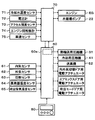
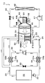
- the vehicle air conditioner 10 includes a water circulation circuit 20, a heat transport refrigeration cycle apparatus 30, a cooling refrigeration cycle apparatus 40, an indoor air conditioning unit 50, an air conditioning control apparatus 60, and the like.
- the water circulation circuit 20 is a circuit that circulates engine cooling water to heat the blown air.
- an antifreeze containing ethylene glycol aqueous solution or the like can be employed.
- the water circulation circuit 20 includes a heater core 21, a water circulation pump 22, a water passage 32 b of the heat-dissipating water-refrigerant heat exchanger 32 of the heat transport refrigeration cycle apparatus 30 described later, and a water passage of the evaporating water-refrigerant heat exchanger 34. 34b etc. are arranged.
- the heater core 21 is disposed in a casing 51 of an indoor air conditioning unit 50, which will be described later, and heat for heating the heated air by exchanging heat between the cooling water heated by the waste heat of the engine EG and the blown air. It is an exchanger.
- a water passage 32b outlet side of the heat radiation water-refrigerant heat exchanger 32 is connected to the cooling water inlet side of the heater core 21, and a water passage of the evaporating water-refrigerant heat exchanger 34 is connected to the cooling water outlet side of the heater core 21. 34b inlet side is connected.
- the water circulation pump 22 is an electric type which sucks the cooling water flowing out from the water passage 34b of the evaporating water-refrigerant heat exchanger 34 on the downstream side of the heater core 21 and pumps it to the cooling water flow path formed in the engine EG. This is a water pump.
- the water circulation pump 22 has its rotational speed (water pressure feeding capacity) controlled by a control signal output from the engine control device 70.
- the cooling water is supplied from the water circulation pump 22 ⁇ the cooling water flow path formed in the engine EG ⁇ the water passage 32 b of the radiating water-refrigerant heat exchanger 32 ⁇ the heater core 21.
- the water passage 34b of the evaporating water-refrigerant heat exchanger 34 ⁇ the water circulation pump 22 is circulated in this order.
- the broken-line arrow shown around the water circulation circuit 20 in the overall configuration diagram of FIG. 1 indicates the flow direction of the cooling water.
- the cooling water flowing through the cooling water flow path from the cooling water outlet side of the engine EG to the cooling water inlet side of the heater core 21 is the upstream cooling described in the claims.
- the cooling water flowing through the cooling water flow path from the cooling water outlet side of the heater core 21 to the cooling water inlet side of the engine EG corresponds to the downstream cooling water described in the claims. Yes.
- a radiator a cooling water bypass passage, a thermostat valve, and the like (not shown) are arranged in the water circulation circuit 20 of the present embodiment.
- the radiator is a heat dissipation heat exchanger that cools the cooling water by exchanging heat between the cooling water and outdoor air (outside air), and is connected in parallel to at least the heater core 21.
- the cooling water bypass passage is a passage through which the cooling water flows by bypassing the radiator.
- the cooling water circuit that flows the cooling water from the cooling water circuit that flows into the radiator to the cooling water bypass passage It is the cooling water circuit switching device which switches to.
- the thermostat valve switches the cooling water circuit as described above, so that, as will be described later, the temperature of the cooling water when the engine EG is operating is a predetermined reference temperature range (this embodiment). In this case, the temperature is generally maintained within 85 ° C. to 95 ° C.).
- the engine EG itself has a temperature equal to or higher than a reference warm-up temperature KTw (specifically, 50 ° C.) regardless of the running state. Warm-up control for intermittently operating the EG is performed. Therefore, in the present embodiment, even when the engine EG does not need to output the driving force for traveling, the temperature of the engine EG itself is maintained at the reference warm-up temperature KTw or higher.
- KTw specifically, 50 ° C.
- the refrigeration cycle apparatus 30 for heat transport is a heat transport section that moves the heat of the cooling water from the low temperature side to the high temperature side in the water circulation circuit 20. More specifically, the heat transport refrigeration cycle apparatus 30 includes a heat transport compressor 31, a heat radiation water-refrigerant heat exchanger 32, a heat transport fixed throttle 33, and an evaporation water-refrigerant heat exchanger 34. This is a compression refrigeration cycle.
- the heat transport compressor 31 compresses and discharges the refrigerant in the heat transport refrigeration cycle apparatus 30 and is an electric compressor that drives a fixed capacity compression mechanism with a fixed discharge capacity by an electric motor.
- various compression mechanisms such as a scroll type compression mechanism and a vane type compression mechanism can be adopted as the fixed capacity type compression mechanism.
- the rotation speed of the electric motor is controlled by a control signal output from the air conditioning control device 60, and either an AC motor or a DC motor may be adopted. And the refrigerant
- the outlet of the heat transport compressor 31 is connected to the inlet side of the refrigerant passage 32 a of the water-refrigerant heat exchanger 32 for heat radiation.
- the heat-dissipating water-refrigerant heat exchanger 32 includes a refrigerant passage 32a through which the high-pressure refrigerant discharged from the heat transport compressor 31 is circulated, and a water passage through which upstream-side cooling water is circulated among the cooling water circulated through the water circulation circuit 20. 32b. And the high-pressure refrigerant
- a water passage 32b is arranged on the outer periphery of the refrigerant passage 32a to exchange heat between the refrigerant and the cooling water, or the refrigerant is circulated as the refrigerant passage 32a.
- the heat-dissipating water-refrigerant heat exchanger 32 a counter flow type heat exchange in which the flow direction of the refrigerant flowing through the refrigerant passage 32a and the flow direction of the hot water flowing through the water passage 32b are opposite flows.
- a vessel is used as the heat-dissipating water-refrigerant heat exchanger 32.
- the heat transport fixed throttle 33 is a heat transport decompression device that decompresses the refrigerant flowing out of the coolant passage 32a.
- a nozzle, an orifice, a capillary tube or the like having a fixed throttle opening can be used as the fixed throttle 33 for heat transport.
- a refrigerant passage 34 a inlet side of the evaporating water-refrigerant heat exchanger 34 is connected to the outlet side of the heat transport fixed throttle 33.
- the evaporating water-refrigerant heat exchanger 34 is water that circulates the downstream side cooling water among the refrigerant passage 34 a that circulates the low-pressure refrigerant decompressed by the fixed throttle 33 for heat transport and the cooling water that circulates in the water circulation circuit 20. It has a passage 34b. And the low-pressure refrigerant
- an evaporating water-refrigerant heat exchanger 34 one having the same configuration as that of the radiating water-refrigerant heat exchanger 32 can be employed.
- the outlet side of the refrigerant passage 34 a of the evaporating water-refrigerant heat exchanger 34 is connected to the suction port side of the heat transport compressor 31.
- the heat absorbed from the downstream cooling water when the refrigerant evaporates in the evaporating water-refrigerant heat exchanger 34 is cooled upstream in the heat radiating water-refrigerant heat exchanger 32. Can dissipate heat to water.
- the cooling refrigeration cycle apparatus 40 is a vapor compression refrigeration cycle for cooling the blown air, and includes a cooling compressor 41, a radiator 42, a cooling expansion valve 43, and an evaporator 44. is doing.
- the cooling compressor 41 compresses and discharges the refrigerant in the cooling refrigeration cycle apparatus 40, and its basic configuration is the same as that of the heat transport compressor 31.
- the cooling compressor 41 has a larger discharge capacity than the heat transport compressor 31.
- the refrigerant inlet side of the radiator 42 is connected to the discharge port of the cooling compressor 41.
- the radiator 42 is disposed on the vehicle front side in the engine room, and exchanges heat between the high-pressure refrigerant discharged from the cooling compressor 41 and outside air (outside air) blown from a blower fan (not shown). This is a heat exchanger for heat dissipation that cools and condenses the high-pressure refrigerant.
- the blower fan is an electric blower in which the rotation speed (the amount of blown air) is controlled by a control voltage output from the air conditioning control device 60.
- the inlet side of the cooling expansion valve 43 is connected to the refrigerant outlet side of the radiator 42.
- the cooling expansion valve 43 is a cooling decompression device that decompresses the refrigerant flowing out of the radiator 42.
- the cooling expansion valve 43 has a temperature sensing unit that detects the degree of superheat of the evaporator 44 outlet-side refrigerant based on the temperature and pressure of the evaporator 44 outlet-side refrigerant, and the degree of superheat of the evaporator 44 outlet-side refrigerant is This is a temperature type expansion valve that adjusts the throttle opening by a mechanical mechanism so as to be within a predetermined reference range.
- the refrigerant inlet side of the evaporator 44 is connected to the outlet side of the cooling expansion valve 43.
- the evaporator 44 is disposed in the casing 51 of the indoor air conditioning unit 50 and exchanges heat between the low-pressure refrigerant decompressed by the cooling expansion valve 43 and the blown air, evaporates the low-pressure refrigerant, and exhibits an endothermic effect. This is an endothermic heat exchanger.
- the refrigerant outlet side of the evaporator 44 is connected to the suction port side of the compressor 11.
- the indoor air conditioning unit 50 is configured integrally with various devices for blowing out the temperature-adjusted blown air into the vehicle interior, and is disposed inside the instrument panel (instrument panel) at the forefront of the vehicle interior. ing. More specifically, the indoor air conditioning unit 50 is configured by housing a blower 52, an evaporator 44 of the cooling refrigeration cycle apparatus 40, a heater core 21 of the water circulation circuit 20, and the like in a casing 51 that forms an outer shell thereof. Yes.
- the casing 51 forms an air passage for blown air that is blown into the passenger compartment, and is formed of a resin (for example, polypropylene) having a certain degree of elasticity and excellent strength.
- An inside / outside air switching device 53 as an inside / outside air switching device for switching and introducing the inside air (vehicle compartment air) and the outside air (vehicle compartment outside air) into the casing 51 is arranged on the most upstream side of the blast air flow in the casing 51. ing.
- the inside / outside air switching device 53 continuously adjusts the opening area of the inside air introduction port through which the inside air is introduced into the casing 51 and the outside air introduction port through which the outside air is introduced by the inside / outside air switching door, so that the air volume of the inside air and the air volume of the outside air are adjusted.
- the air volume ratio is continuously changed.
- the inside / outside air switching door is driven by an electric actuator for the inside / outside air switching door, and the operation of this electric actuator is controlled by a control signal output from the air conditioning control device 60.
- a blower (blower) 52 for blowing the air sucked through the inside / outside air switching device 53 toward the vehicle interior is arranged.
- the blower 52 is an electric blower that drives a centrifugal multiblade fan (sirocco fan) with an electric motor, and the number of rotations (the amount of blown air) is controlled by a control voltage output from the air conditioning control device 60.
- the evaporator 44 and the heater core 21 are arranged in this order with respect to the flow of the blown air on the downstream side of the blower air flow of the blower 52. That is, the evaporator 44 is disposed upstream of the blower air flow with respect to the heater core 21. Further, in the casing 51, a cold air bypass passage 55 is formed in which the blown air that has passed through the evaporator 44 bypasses the heater core 21 and flows downstream.
- An air mix door 54 that adjusts the air volume ratio with the air volume that passes the air is disposed.
- a mixing space for mixing the blown air heated by the heater core 21 and the blown air that has passed through the cold air bypass passage 55 is provided. Furthermore, the opening hole which blows off the ventilation air (air conditioning wind) mixed in the mixing space to the vehicle interior which is an air-conditioning object space is arrange
- the opening hole includes a face opening hole that blows air-conditioned air toward the upper body of the passenger in the passenger compartment, a foot opening hole that blows air-conditioned air toward the feet of the passenger, and an inner surface of the front window glass of the vehicle.
- a defroster opening hole (both not shown) for blowing the conditioned air toward is provided.
- the air flow downstream of the face opening hole, foot opening hole and defroster opening hole is respectively connected to the face air outlet, foot air outlet and defroster air outlet provided in the vehicle interior via ducts forming air passages. It is connected to an outlet (both not shown).
- the air mix door 54 adjusts the air volume ratio between the air volume that passes through the heater core 21 and the air volume that passes through the cold air bypass passage 55, thereby adjusting the temperature of the conditioned air mixed in the mixing space.
- the temperature of the blast air (air conditioned air) blown out from the air outlet into the vehicle compartment is adjusted.
- the air mix door 54 constitutes a temperature adjustment device that adjusts the temperature of the conditioned air blown into the vehicle interior.
- the air mix door 54 is driven by an electric actuator for driving the air mix door, and the operation of this electric actuator is controlled by a control signal output from the air conditioning control device 60.
- a face door for adjusting the opening area of the face opening hole a foot door for adjusting the opening area of the foot opening hole, and a defroster opening, respectively.
- a defroster door (both not shown) for adjusting the opening area of the hole is disposed.
- blower outlet mode door that switches the blower outlet mode, and for driving the blower outlet mode door via a link mechanism or the like (not shown). It is connected to the electric actuator and is rotated in conjunction with it. The operation of this electric actuator is also controlled by a control signal output from the air conditioning controller 60.
- the face air outlet, the face air outlet and the foot air outlet which opens the face air outlet fully and blows air from the face air outlet toward the upper body of the passenger in the passenger compartment.
- the bi-level mode that opens both of the air outlets and blows air toward the upper body and feet of passengers in the passenger compartment, fully opens the foot outlet and opens the defroster outlet by a small opening, and mainly draws air from the foot outlet.
- the defroster mode in which the occupant manually operates the blowing mode changeover switch provided on the operation panel to fully open the defroster outlet and blow out air from the defroster outlet to the inner surface of the front windshield of the vehicle.
- the engine control device 70 and the air conditioning control device 60 are configured by a known microcomputer including a CPU, a ROM, a RAM, and the like and peripheral circuits thereof. Then, various operations and processes are performed based on the control program stored in the ROM to control the operation of various devices connected to the output side.
- various engine constituent devices that constitute the engine EG are connected to the output side of the engine control device 70. Specifically, a starter for starting the engine EG, a drive circuit for a fuel injection valve (injector) for supplying fuel to the engine EG, and the like are connected.
- a cooling water temperature sensor 71 for detecting the cooling water temperature Tw flowing out of the engine EG, a voltmeter 72 for detecting the battery voltage VB, and an accelerator opening Acc are detected.
- An engine opening sensor 73, an engine speed sensor 74 for detecting the engine speed Ne, and a vehicle speed sensor 75 for detecting the vehicle speed Vv are connected.
- the air-conditioning control device 60 On the output side of the air-conditioning control device 60, there are a heat transport compressor 31, a cooling compressor 41, a blower 52, an inside / outside air switching door, an air mix door, and an electric actuator for driving to drive the outlet mode door.
- Various air conditioning control devices are connected.
- the air-conditioning control device 60 is configured integrally with a control device that controls various air-conditioning control devices connected to the output side of the air-conditioning control device 60.
- Software constitutes a control device for controlling the operation of each air conditioning control device.
- the configuration for controlling the operation of the heat transport refrigeration cycle apparatus 30 constitutes the heat transport control unit 60a.
- an inside air sensor 61 that detects the vehicle interior temperature Tr
- an outside air sensor 62 that detects the outside air temperature Ta
- a solar radiation sensor 63 that detects the amount of solar radiation As in the vehicle interior
- an evaporator 44 A sensor group for air conditioning control, such as an evaporator temperature sensor 64 (evaporator temperature detector) for detecting the refrigerant evaporation temperature (evaporator temperature) Tefin, an air temperature sensor 65 for detecting the air temperature TAV blown into the passenger compartment. Is connected.
- an operation panel 80 disposed near the instrument panel in the front of the passenger compartment is connected to the input side of the air conditioning control device 60, and operation signals of various air conditioning operation switches provided on the operation panel 80 are sent to the air conditioning control device. 60.
- an operation switch for requesting operation or stop of the vehicle air conditioner 1 a temperature setting switch for setting the set temperature Tset in the vehicle interior, an operation mode changeover switch for setting the operation mode, An air outlet mode changeover switch, an air volume setting switch of the blower 52, and the like are provided.
- the engine control device 70 and the air conditioning control device 60 of the present embodiment are configured to be communicable with each other by being electrically connected to each other. Thereby, based on the detection signal or operation signal input into one control apparatus, the other control apparatus can also control the operation
- the engine control device 70 calculates the traveling load of the vehicle based on the detection signals of the above-described engine control sensor groups 71 to 75, and the engine EG is turned on according to the traveling load. Activate or deactivate. Furthermore, the engine control device 70 operates the water circulation pump 22 so as to exhibit a predetermined water pressure feeding capability when the vehicle is started.
- the cooling water circulating in the water circulation circuit 20 absorbs the waste heat of the engine EG and cools the engine EG as it flows through the cooling water flow path formed in the engine EG.
- the thermostat valve of the water circulation circuit 20 when the temperature of the cooling water passing through the thermostat valve of the water circulation circuit 20 is equal to or lower than the reference switching temperature, the thermostat valve switches to the cooling water circuit that flows the cooling water to the cooling water bypass passage side.
- the waste heat of the engine EG that has absorbed heat is not radiated to the atmosphere by the radiator.
- the thermostat valve switches the cooling water circuit so that the temperature of the cooling water and the engine EG itself is maintained within a predetermined reference temperature range (approximately 85 ° C. to 95 ° C. in this embodiment). Is done.
- the coolant temperature Tw detected by the coolant temperature sensor 71 even when the engine EG does not need to be operated to output the driving force for vehicle travel. Is controlled to operate the engine EG so as to be higher than the reference warm-up temperature KTw (in this embodiment, 50 ° C.).
- the reference warm-up temperature KTw it is desirable to set the reference warm-up temperature KTw to a temperature higher than 50 ° C. in order to suppress an increase in friction loss at the time of restart and malfunction of the exhaust gas purification catalyst.
- the reference warm-up temperature KTw is set to a temperature higher than 50 ° C., the frequency of operating the engine EG increases when it is not necessary to operate the engine EG in order to output the driving force for traveling the vehicle. End up.
- the warm-up control according to the present embodiment it is possible to suppress the increase in friction loss at the time of restart and the malfunction of the exhaust gas purifying catalyst, and to set the reference warm-up as a temperature that does not unnecessarily deteriorate the vehicle fuel consumption.
- the machine temperature KTw is set to 50 ° C.
- the operation of the vehicle air conditioner 10 will be described.
- a cooling mode in which the cooled blown air is blown into the vehicle interior based on an operation signal of the operation mode changeover switch of the operation panel 80, a cooling mode in which the cooled blown air is blown into the vehicle interior, and a heating in which the heated blown air is blown into the vehicle interior.
- the mode and the dehumidifying and heating mode in which the blown air that has been cooled and dehumidified is reheated and blown out into the passenger compartment can be switched. The operation in each operation mode will be described below.
- Cooling mode The cooling mode is executed when the operation switch of the operation panel 80 is turned on (ON) and the cooling mode is selected by the operation mode switch.
- the air conditioning control device 60 reads the detection signals of the air conditioning control sensor groups 61 to 65 and the operation signals of the operation panel 80 described above. Then, a target blowing temperature TAO that is a target temperature of air blown into the vehicle interior is calculated based on the read detection signal and operation signal values.
- the target blowing temperature TAO is calculated by the following formula F1.
- TAO Kset ⁇ Tset ⁇ Kr ⁇ Tr ⁇ Kam ⁇ Tam ⁇ Ks ⁇ As + C (F1)
- Tr is the vehicle interior temperature (internal air temperature) detected by the internal air sensor 61
- Tam is the external air temperature detected by the external air sensor 62
- I the amount of solar radiation detected by the solar radiation sensor 63.
- Kset, Kr, Kam, Ks are control gains
- C is a correction constant.
- control signals to be output to various air conditioning control devices connected to the output side of the air conditioning control device 60 are determined.
- control signal output to the electric motor of the cooling compressor 41 of the cooling refrigeration cycle apparatus 40 is determined as follows.
- the target evaporator outlet temperature TEO of the evaporator 44 is determined with reference to a control map stored in the air conditioning controller 60 in advance. This target evaporator outlet temperature TEO is determined so as to decrease as the target outlet temperature TAO decreases so that the outlet air temperature TAV approaches the target outlet temperature TAO.
- the evaporator temperature Tefin approaches the target evaporator outlet temperature TEO using a feedback control method.
- a control signal output to the electric motor of the cooling compressor 41 is determined.
- control voltage (blower motor voltage) output to the electric motor of the blower 52 is determined so as to be substantially maximum in the extremely low temperature range (maximum cooling range) and the extremely high temperature range (maximum heating range) of the TAO. Further, as the TAO moves from the extremely low temperature region or the extremely high temperature region to the intermediate temperature region, the blower motor voltage is determined to be gradually decreased from the substantially maximum value.
- the air mix door 54 closes the air passage on the heater core 21 side, and the total air volume of the blown air after passing through the evaporator 44 is the cold air bypass passage 55. Decide to pass.
- the outside air mode in which outside air is introduced is basically given priority.
- TAO is in a very low temperature range and high cooling performance is desired. It decides to become a shy mode to introduce shyness into.
- the air outlet mode As for the control signal output to the electric actuator for the air outlet mode door, as the TAO rises from the low temperature range to the high temperature range, the air outlet mode is switched from foot mode to bi-level mode to face mode. To be determined. Accordingly, the face mode is mainly selected in the summer, the bi-level mode is mainly selected in the spring and autumn, and the foot mode is mainly selected in the winter.
- control signal output to the electric motor of the heat transport compressor 31 of the heat transport refrigeration cycle apparatus 30 is determined so as to stop the operation of the heat transport compressor 31.
- control signals determined as described above are output to various air conditioning control devices.
- the above detection signal and operation signal are read at every predetermined control cycle ⁇ the target blowing temperature TAO is calculated ⁇ the operating states of various air conditioning control devices
- a control routine such as decision-> output of control voltage and control signal is repeated. Such a control routine is repeated in the other operation modes.
- the blown air (cold air) cooled by the evaporator 44 of the cooling refrigeration cycle apparatus 40 is blown out into the vehicle interior via the cold air bypass passage 55, the mixing space, and each outlet. .
- the passenger compartment is cooled.
- Heating mode is executed when the heating mode is selected by the operation mode changeover switch in a state where the operation switch of the operation panel 80 is turned on (ON).
- the air conditioning control device 60 In the heating mode, as in the cooling mode, the air conditioning control device 60 generates control signals or control voltages to be output to various air conditioning control devices based on the target blowing temperature TAO and the detection signals of the air conditioning control sensor groups 61 to 65. decide.
- control signal output to the electric motor of the cooling compressor 41 is determined so as to stop the operation of the cooling compressor 41. Further, the control signal output to the electric actuator for the air mix door 54 is determined so that the blown air temperature TAV detected by the blown air temperature sensor 65 approaches the target blown temperature TAO using a feedback control method.
- Other air conditioning control devices are the same as in the cooling mode.
- the temperature adjustment is performed so that the blown air (hot air) heated by the heater core 21 and the blown air that has passed through the cold air bypass passage 55 are mixed in the mixing space so as to approach the target blowing temperature TAO.
- the conditioned air thus blown out into the passenger compartment through each outlet. Thereby, the vehicle interior is heated.
- (C) Dehumidifying heating mode The heating mode is executed when the dehumidifying heating mode is selected by the operation mode changeover switch in a state where the operation switch of the operation panel 80 is turned on (ON).
- the air conditioning control device 60 outputs control signals to various air conditioning control devices based on the target blowing temperature TAO and the detection signals of the air conditioning control sensor groups 61 to 65, as in the cooling mode and the heating mode. Determine the control voltage and the like.
- control signal output to the electric motor of the cooling compressor 41 is determined such that the evaporator temperature Tefin is equal to or higher than a predetermined reference evaporator temperature (specifically, 1 ° C.).
- the reference evaporator temperature is determined so that frost formation does not occur in the evaporator 44.
- Other air conditioning control devices are the same as in the heating mode.
- the blown air (cold air) cooled and dehumidified by the evaporator 44 is reheated by the heater core 21.
- the reheated blown air (warm air) and the blown air (cold air) that has passed through the cold air bypass passage 55 are mixed in the mixing space, thereby adjusting the temperature of the conditioned air so as to approach the target blowing temperature TAO. Is blown out into the passenger compartment through each outlet. Thereby, dehumidification heating in the passenger compartment is performed.
- the vehicle air conditioner 10 of the present embodiment it is possible to perform cooling, heating, and dehumidifying heating in the passenger compartment.
- the blown air is heated using the cooling water of the engine EG as a heat source during heating of the vehicle interior and during dehumidifying heating.
- the temperature of the cooling water flowing into the heater core 21 does not rise above the temperature required to perform heating or dehumidifying heating in the vehicle interior, The blown air that is generated cannot be sufficiently heated, and the passenger's feeling of heating is deteriorated.
- the engine EG is operated so that the coolant temperature Tw becomes the reference warm-up temperature KTw (specifically, 50 ° C.). Yes. For this reason, if heating of a vehicle interior or dehumidification heating is performed during execution of warm-up control, the passenger's feeling of heating may be deteriorated.
- the heating determination temperature KHTw of the present embodiment is set to 60 ° C. as the cooling water temperature necessary to sufficiently heat the blown air so as not to deteriorate the passenger's feeling of heating.
- the heat transport control unit 60a of the air conditioning control device 60 operates the compressor 31 for heat transport of the refrigeration cycle device 30 for heat transport. More specifically, the heat transport control unit 60a is determined so that the temperature of the upstream cooling water flowing into the heater core 21 is equal to or higher than the heating determination temperature KHTw with respect to the electric motor of the heat transport compressor 31. Output a control signal.
- the high-pressure refrigerant discharged from the heat transport compressor 31 flows into the refrigerant passage 32a of the heat-dissipating water-refrigerant heat exchanger 32 and flows upstream through the water passage 32b. Heat exchange with cooling water to dissipate heat. Thereby, the temperature of the upstream side cooling water flowing into the heater core 21 is heated to the heating determination temperature KHTw or higher.
- the refrigerant that has flowed out of the refrigerant passage 32 a of the heat-dissipating water-refrigerant heat exchanger 32 is decompressed by the heat transport fixed throttle 33.
- the low-pressure refrigerant decompressed by the heat transport fixed throttle 33 flows into the refrigerant passage 34a of the evaporating water-refrigerant heat exchanger 34, evaporates by exchanging heat with the downstream cooling water flowing through the water passage 34b. Thereby, the temperature of the downstream side cooling water flowing into the engine EG is lower than that in the heating mode or the dehumidifying heating mode.
- the refrigerant that has flowed out of the refrigerant passage 34a of the evaporating water-refrigerant heat exchanger 34 is sucked into the heat transport compressor 31 and compressed again.
- the temperature of the upstream side cooling water flowing into the heater core 21 can be heated to the heating determination temperature KHTw or higher by the water for radiating water-refrigerant heat exchanger 32. Therefore, the blower air can be sufficiently heated by the heater core 21, and the deterioration of the passenger's feeling of heating can be suppressed.
- the engine EG is not operated to increase the temperature of the upstream side cooling water flowing into the heater core 21 when it is not necessary to output the driving force for traveling the vehicle. Even if the fuel is consumed to operate the refrigeration cycle apparatus 30 for heat transportation, it is possible to comprehensively suppress the deterioration of the vehicle fuel consumption.
- a normal vehicle air conditioner hereinafter referred to as a comparative air conditioner
- a comparative air conditioner applied to a hybrid vehicle in which the reference warm-up temperature KTw in the warm-up control is set to 60 ° C. This will be described in comparison with the heating mode or the dehumidifying heating mode.
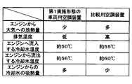
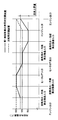
- the temperature of the engine EG itself during warm-up control is higher than that of the hybrid vehicle of the present embodiment. For this reason, the temperature difference between the temperature of the engine EG itself and the outside air temperature increases, and the amount of heat released from the engine EG itself to the atmosphere increases as shown in the chart of FIG. Furthermore, since the temperature of the exhaust gas also rises, the amount of heat released to the atmosphere via the exhaust gas increases.
- the downstream-side cooling water and the engine EG flowing into the engine EG are compared to the heating mode or the dehumidifying heating mode of the comparative air conditioner.
- the temperature of the upstream cooling water flowing out from the tank becomes low. For this reason, the temperature difference between the engine EG and the cooling water increases, and the amount of heat absorbed by the cooling water from the engine EG increases.
- the heat generated when the engine EG consumes fuel is higher than in the heating mode or the dehumidifying heating mode of the comparative air conditioner.
- the ratio of heat that is thrown away into the atmosphere can be reduced, and the waste heat of the engine EG can be efficiently absorbed into the cooling water.
- the cooling water temperature at the cooling water outlet of the engine EG relative to the cooling water temperature at the cooling water inlet of the engine EG. Can be made larger than the heating mode or the dehumidifying heating mode of the comparative air conditioner.
- the heat absorbed efficiently can be used for heating or dehumidifying heating in the passenger compartment, and the vehicle fuel consumption is deteriorated overall. Can be suppressed.
- the vehicle air conditioner 10 of the present embodiment it is possible to achieve both suppression of deterioration in vehicle fuel consumption and suppression of deterioration in passenger heating feeling.
- the vehicle air conditioner 10 of the present embodiment it is possible to suppress the deterioration of the passenger's feeling of heating without incurring deterioration of the vehicle fuel consumption.
- the amount of electric power necessary for operating the heat transport compressor 31 of the heat transport refrigeration cycle apparatus 30 during the strong heating mode or the strong dehumidifying heating mode is determined by operating the engine EG. It has been found that the amount of surplus power stored in the battery is less than the amount of surplus power stored during the running conditions.
- the engine EG is hardly operated only to operate the heat transport refrigeration cycle apparatus 30, and even if the heat transport refrigeration cycle apparatus 30 is operated, the vehicle fuel consumption is hardly deteriorated. .
- surplus power stored in the battery can be effectively utilized for heating or dehumidifying heating in the vehicle interior.
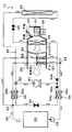
- the heater core 21 of the present embodiment has a plurality (two in the present embodiment) of heat exchange portions 21a and 21b arranged in series with the flow of the blown air.
- the windward side heat exchange unit 21a those arranged on the upstream side of the blast air flow are referred to as the windward side heat exchange unit 21a, and those arranged on the downstream side of the blast air flow are referred to as the leeward side heat exchange unit 21b.
- the windward side heat exchange unit 21a those arranged on the upstream side of the blast air flow
- the leeward side heat exchange unit 21b those arranged on the downstream side of the blast air flow
- the branch portion 23 that branches the flow of the upstream side cooling water flowing out from the engine EG, and the flow of the cooling water that flows out from the windward side heat exchanging portion 21a and the leeward side heat exchanging portion.
- a merging portion 24 for merging the flow of cooling water that has flowed out of 21b is disposed.
- the branch portion 23 is configured by a three-way joint having three inflow / outflow ports, and one of the three inflow / outflow ports is a cooling water inflow port and the remaining two are cooling water outflow ports.
- a three-way joint may be formed by joining pipes having different pipe diameters, or may be formed by providing a plurality of cooling water passages in a metal block or a resin block.
- One cooling water outlet of the branch portion 23 is connected to the inlet side of the water passage 32b of the water for radiating water-refrigerant heat exchanger 32, and on the outlet side of the water passage 32b of the water for radiating water-refrigerant heat exchanger 32, The cooling water inlet side of the leeward side heat exchanging portion 21b is connected. Further, the other cooling water outlet of the branch part 23 is connected to the cooling water inlet side of the windward heat exchange part 21a.
- the upstream side cooling water that has flowed out from one cooling water outlet of the branch portion 23 is used as the heat radiation water-refrigerant heat exchanger 32. After being heated at, it is made to flow into the leeward side heat exchanging part 21b and to allow the upstream side cooling water flowing out from the other cooling water outlet of the branching part 23 to flow into the leeward side heat exchanging part 21a.
- the passage sectional area of one cooling water outlet side of the cooling water passages in the branching portion 23 is formed smaller than the passage sectional area of the other cooling water outlet side. Therefore, the leeward flow rate Q2 of the cooling water flowing through the leeward heat exchange unit 21b is smaller than the leeward flow rate Q1 of the cooling water flowing through the windward heat exchange unit 21a. More specifically, the leeward flow rate Q2 of the present embodiment is about 1/15 of the leeward flow rate Q1.
- the confluence 24 is composed of a three-way joint similar to the branch 23, and two of the three inflow / outflow ports are cooling water inflow ports, and the remaining one is a cooling water outflow port.
- An inlet side of the water passage 34 b of the evaporating water-refrigerant heat exchanger 34 is connected to the cooling water outlet of the junction 24.
- the refrigerant of the heat transport refrigeration cycle apparatus 30 flows out of the windward heat exchange unit 21a in the evaporating water-refrigerant heat exchanger 34. It absorbs and evaporates the heat of the downstream cooling water, which is a combination of the cooling water flow and the cooling water flow that has flowed out of the leeward heat exchange section 21b.
- the heater core 21 has two heat exchanging parts, the windward side heat exchanging part 21a and the leeward side heat exchanging part 21b, and the cooling water flowing out from the engine EG is used as wind. Cooling water that has flowed into the upper heat exchanging portion 21a and has flowed out of the water passage 32b of the heat-dissipating water-refrigerant heat exchanger 32 is caused to flow into the leeward heat exchanging portion 21b.
- the temperature of the upstream cooling water flowing into the leeward heat exchange unit 21b is higher than the temperature of the upstream cooling water flowing into the leeward heat exchange unit 21a. According to this, in both heat exchanging parts 21a and 21b, a temperature difference between cooling water and blown air can be secured, and blown air can be efficiently heated.
- the leeward flow rate Q2 of the cooling water flowing through the leeward heat exchange unit 21b is less than the leeward flow rate Q1 of the cooling water flowing through the windward heat exchange unit 21a. Therefore, the flow rate of the cooling water flowing through the water passage 32b of the heat-dissipating water-refrigerant heat exchanger 32 can be reduced compared to the first embodiment.
- the heat absorption amount that the cooling water absorbs heat from the high-pressure refrigerant in the heat radiation water-refrigerant heat exchanger 32 that is, the heat radiation amount that the refrigerant radiates heat to the cooling water in the heat radiation water-refrigerant heat exchanger 32 decreases. Therefore, the cycle balance in the heat transport refrigeration cycle apparatus 30 changes so as to increase the refrigerant pressure (refrigerant condensation temperature) in the refrigerant passage 32a of the heat-dissipating water-refrigerant heat exchanger 32.
- the heat radiation water-refrigerant heat exchanger 32 is heated without increasing the rotational speed of the heat transport compressor 31 compared to the first embodiment.
- the temperature of the cooling water can be increased.
- the blower air can be sufficiently heated by the heater core 21, and the deterioration of the passenger's feeling of heating can be suppressed more reliably.
- the flow of the cooling water and the leeward heat flowing out from the windward heat exchange unit 21a to the refrigerant of the refrigeration cycle device 30 for heat transport is carried.
- the heat which the downstream side cooling water which merged with the flow of the cooling water which flowed out from exchange part 21b has absorbed heat.
- the heat absorption amount does not become insufficient as in the case of absorbing the heat of the cooling water that has flowed out of any one of the heat exchange sections, and the heater core in the radiating water-refrigerant heat exchanger 32 It is possible to reliably heat the temperature of the upstream-side cooling water flowing into 21 to the heating determination temperature KHTw or higher.
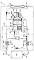
- the heater core 21 of the present embodiment includes the windward side heat exchange unit 21a and the leeward side heat exchange unit 21b similar to those of the second embodiment.
- the branch part 23 is arrange
- One cooling water outlet of the branch portion 23 of the present embodiment is connected to the inlet side of the water passage 32b of the radiating water-refrigerant heat exchanger 32, and the outlet of the water passage 32b of the radiating water-refrigerant heat exchanger 32 is connected.
- the cooling water inlet side of the leeward side heat exchanging portion 21b is connected to the side.
- one cooling water inlet of the merging portion 24 is connected to the other cooling water outlet of the branching portion 23, and the other cooling of the merging portion 24 is connected to the cooling water outlet side of the leeward side heat exchanging portion 21b. A water inlet is connected.
- the upstream side cooling water that has flowed out from one cooling water outlet of the branch portion 23 is used as the heat radiation water-refrigerant heat exchanger 32.
- the cooling water that has flowed from the cooling water outlet that flows out from the other cooling water outlet of the branch portion 23 is merged with the cooling water that has flowed out from the leeward heat exchange portion 21b. Yes.
- cooling, heating, and dehumidifying heating in the passenger compartment can be performed. Further, when the cooling water temperature Tw is equal to or lower than the heating determination temperature KHTw, by performing the operation in the strong heating mode and the strong dehumidifying heating mode, the passenger's feeling of heating is not caused without deteriorating the vehicle fuel consumption. Can be prevented.
- the heater core 21 since the heater core 21 has the two heat exchange parts 21a and 21b arranged in series with respect to the flow of blowing air, it is the same as in the second embodiment. The effect of can be obtained.
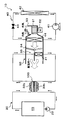
- the basic configuration of the compressor 91 of the present embodiment is the same as the heat transport compressor 31 and the cooling compressor 41. Further, in the present embodiment, a compressor having a larger discharge capacity than the cooling compressor 41 is employed as the compressor 91.
- the cooling water inlet side of the three-way flow rate adjustment valve 92 is connected to the discharge port of the cooling compressor 41.
- the basic configuration of the compressor 91 is the same as that of the heat transport compressor 31 and the cooling compressor 41. Further, in the present embodiment, a compressor having a larger discharge capacity than the cooling compressor 41 is employed as the compressor 91.
- the cooling water inlet side of the three-way flow rate adjustment valve 92 is connected to the discharge port of the cooling compressor 41.
- the three-type flow rate adjusting valve 92 is an electric type that adjusts the flow rate ratio between the refrigerant flow rate flowing into the heat radiating water-refrigerant heat exchanger 32 and the refrigerant flow rate flowing into the radiator 42 among the refrigerant discharged from the compressor 91. This is a flow regulating valve. The operation of the three-type flow rate adjusting valve 92 is controlled by a control signal output from the air conditioning control device 60.
- the three-system flow rate adjusting valve 92 of the present embodiment can cause the entire flow rate of the refrigerant discharged from the compressor 91 to flow into the radiator 42 or flow into the heat radiating water-refrigerant heat exchanger 32. Therefore, the three-system flow rate adjustment valve 92 of the present embodiment also has a function as a refrigerant circuit switching device that switches the refrigerant circuit.
- One refrigerant outlet of the three-mode flow rate adjusting valve 92 is connected to a suction port of the compressor 91 via a heat-dissipating water-refrigerant heat exchanger 32, a heat transport fixed throttle 33, and an evaporating water-refrigerant heat exchanger 34.
- the side is connected.
- the refrigerant path from the outlet side of the refrigerant passage 34a of the evaporating water-refrigerant heat exchanger 34 to the inlet side of the compressor 91 is connected to the compressor from the outlet side of the refrigerant passage 34a of the evaporating water-refrigerant heat exchanger 34.
- a check valve 93a for heat transport that only allows the refrigerant to flow to the suction port side of 91 is disposed.
- the other refrigerant outlet of the three-type flow rate adjusting valve 92 is connected to the suction port side of the compressor 91 via the radiator 42, the cooling expansion valve 43, and the evaporator 44. Further, the cooling passage that allows only the refrigerant to flow from the refrigerant outlet side of the evaporator 44 to the suction port side of the compressor 91 in the refrigerant path from the refrigerant outlet side of the evaporator 44 to the suction port side of the compressor 91.
- a check valve 93b is arranged.
- Other configurations are the same as those of the second embodiment.
- the air conditioning control device 60 operates the compressor 91 in the same manner as in the second embodiment, and the total flow rate of the refrigerant discharged from the compressor 91 is changed to the radiator 42.
- the operation of the three-type flow rate adjusting valve 92 is controlled so as to flow into.
- the air conditioning control device 60 stops the compressor 91. Further, in the dehumidifying and heating mode, the air conditioning control device 60 operates the compressor 91 in the same manner as in the second embodiment so that the total flow rate of the refrigerant discharged from the compressor 91 flows into the radiator 42. The operation of the flow rate adjustment valve 92 is controlled.
- the air conditioning control device 60 operates the compressor 91 so as to exhibit the refrigerant discharge capacity equivalent to that in the heating mode and the dehumidifying heating mode. Further, the operation of the three-type flow rate adjustment valve 92 is performed so that a part of the refrigerant discharged from the compressor 91 flows into the radiator 42 and the remaining refrigerant flows into the refrigerant passage 32a of the water-refrigerant heat exchanger 32 for heat radiation. To control. Other operations are the same as those in the second embodiment.
- the vehicle air conditioner 10 of this embodiment operates in exactly the same way as in the second embodiment, and can obtain the same effect. Furthermore, in this embodiment, since the compressor for heat transport 31 and the compressor for cooling 41 are used in common and one compressor 91 is employed, the vehicle air conditioner 10 as a whole can be reduced in size and manufacturing cost. Can be reduced.
- the inlet side of the refrigerant passage 32a of the heat-dissipating water-refrigerant heat exchanger 32 is connected to the discharge port side of the compressor 91, and the refrigerant of the radiator 42 is connected to the outlet side of the refrigerant passage 32a.
- the inlet side is connected.
- a refrigerant branching portion 94 that branches the flow of the refrigerant flowing out of the radiator 42 is disposed on the refrigerant outlet side of the radiator 42.
- the inlet side of the compressor 91 is connected to one of the refrigerant outlets of the refrigerant branch portion 94 via the heat transport fixed throttle 33, the evaporating water-refrigerant heat exchanger 34, and the heat transport check valve 93a.
- the other refrigerant outlet of the refrigerant branch portion 94 is connected to the suction port side of the compressor 91 via the cooling expansion valve 43, the evaporator 44, and the cooling check valve 93b.
- Other configurations are the same as those of the second embodiment.
- the operation of the vehicle air conditioner of the present embodiment having the above configuration will be described.
- the refrigerant discharged from the compressor 91 flows into the refrigerant passage 32a of the water-refrigerant heat exchanger 32 for heat radiation when the compressor 91 is operated, the operation in the strong heating mode and the dehumidifying heating mode is performed. Is not executed.
- the air conditioning control device 60 operates the compressor 91 as in the fourth embodiment.
- the air conditioning control device 60 stops the compressor 91.
- the air conditioning control device 60 operates the compressor 91 so as to exhibit the refrigerant discharge capacity equivalent to that of the fourth embodiment.
- Other operations are the same as those in the fourth embodiment.
- the cooling water and the refrigerant discharged from the compressor 91 exchange heat in the heat-dissipating water-refrigerant heat exchanger 32, but the air mix door 54 is on the heater core 21 side. Since the air passage is closed, the vehicle interior can be cooled as in the second embodiment. In the heating mode, the passenger compartment can be heated just as in the second embodiment.
- the cooling water heated to the heating determination temperature KHTw (specifically, 60 ° C.) or higher in the heat radiating water-refrigerant heat exchanger 32 is caused to flow into the leeward heat exchange unit 21b. Therefore, as in the second embodiment, it is possible to suppress the deterioration of the passenger's feeling of heating without causing deterioration of the vehicle fuel consumption.
- the entire vehicle air conditioner 10 is similar to the fourth embodiment. Thus, it is possible to reduce the size and the manufacturing cost.
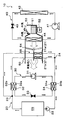
- the Peltier device 100 is used as a heat transport part. Adopted.
- the Peltier element 100 is a plate-like semiconductor element that utilizes the Peltier effect, and is supplied with electric power from the air-conditioning control device 60, whereby the heat absorbed by one surface can be dissipated to the other surface.
- the water passage 34b for circulating the downstream side cooling water is joined to one surface of the Peltier element 100, and the water passage 32b for circulating the upstream side cooling water is joined to the other surface.
- the heat absorbed from the downstream side cooling water flowing through the water passage 34b can be radiated to the upstream side cooling water flowing through the water passage 32b.
- the heat transport control unit 60a of this embodiment controls the operation of the Peltier element 100. Specifically, the heat transport control unit 60a of the present embodiment supplies power to the Peltier element 100 in the strong heating mode or the strong dehumidifying heating mode. Other configurations and operations are the same as those in the first embodiment. Therefore, also in the vehicle air conditioner 10 of the present embodiment, the same effect as in the first embodiment can be obtained.
- the heater core 21 has been described as having two heat exchanging parts, the windward side heat exchanging part 21a and the leeward side heat exchanging part 21b. As long as it has at least two heat exchange units arranged in series with respect to the air flow, it may have three or more heat exchange units.
- the leeward flow rate Q2 of the cooling water flowing through the leeward heat exchange unit 21b is greater than the leeward flow rate Q1 of the cooling water flowing through the windward heat exchange unit 21a.
- the windward flow volume Q1 and the leeward flow volume Q2 may be equivalent.
- the elements and devices disclosed in each of the above embodiments may be appropriately combined within a feasible range.
- the heat transport compressor 31 of the heat transport refrigeration cycle apparatus 30 and the cooling compressor 41 of the cooling refrigeration cycle apparatus 40 described in the first and third embodiments are used as a common compressor 91
- the fourth As described in the fifth embodiment, the heat transport refrigeration cycle apparatus 30 and the cooling refrigeration cycle apparatus 40 may be integrally configured as one refrigeration cycle apparatus 90.
- the Peltier element 100 may be employed as the heat transport unit.
Abstract
Selon l'invention, un radiateur de chauffage (21) qui est disposé dans un circuit de circulation d'eau (20) faisant circuler de l'eau de refroidissement pour un moteur (moteur à combustion interne) (EG) délivrant en sortie une force motrice destinée à faire se déplacer un véhicule, ledit radiateur de chauffage échangeant de la chaleur entre l'eau de refroidissement et l'air de ventilation insufflé dans l'habitacle du véhicule, et chauffant l'air de ventilation. Lorsque la température de l'eau de refroidissement qui s'est écoulée hors du moteur (EG) a chuté, un dispositif à cycle de réfrigération de transport de chaleur (30), qui fait office d'unité de transport de chaleur absorbant la chaleur d'une eau de refroidissement côté aval du côté aval du radiateur de chauffage (21) et dissipant la chaleur vers une eau de refroidissement côté amont du côté amont du radiateur de chauffage (21), est activé sans activer le moteur (EG), et la température de l'eau de refroidissement qui s'écoule dans le radiateur de chauffage (21) est élevée à une température nécessaire pour chauffer l'habitacle du véhicule.
Priority Applications (3)
| Application Number | Priority Date | Filing Date | Title |
|---|---|---|---|
| US15/307,849 US10899198B2 (en) | 2014-05-13 | 2015-04-27 | Air conditioner for vehicle |
| DE112015002259.7T DE112015002259T5 (de) | 2014-05-13 | 2015-04-27 | Klimaanlage für ein Fahrzeug |
| CN201580024903.6A CN106457968B (zh) | 2014-05-13 | 2015-04-27 | 车辆用空调装置 |
Applications Claiming Priority (2)
| Application Number | Priority Date | Filing Date | Title |
|---|---|---|---|
| JP2014-099635 | 2014-05-13 | ||
| JP2014099635A JP6269307B2 (ja) | 2014-05-13 | 2014-05-13 | 車両用空調装置 |
Publications (1)
| Publication Number | Publication Date |
|---|---|
| WO2015174035A1 true WO2015174035A1 (fr) | 2015-11-19 |
Family
ID=54479587
Family Applications (1)
| Application Number | Title | Priority Date | Filing Date |
|---|---|---|---|
| PCT/JP2015/002261 WO2015174035A1 (fr) | 2014-05-13 | 2015-04-27 | Dispositif de climatisation pour véhicule |
Country Status (5)
| Country | Link |
|---|---|
| US (1) | US10899198B2 (fr) |
| JP (1) | JP6269307B2 (fr) |
| CN (1) | CN106457968B (fr) |
| DE (1) | DE112015002259T5 (fr) |
| WO (1) | WO2015174035A1 (fr) |
Cited By (1)
| Publication number | Priority date | Publication date | Assignee | Title |
|---|---|---|---|---|
| US20220371397A1 (en) * | 2021-05-19 | 2022-11-24 | Toyota Jidosha Kabushiki Kaisha | In-vehicle temperature adjustment system |
Families Citing this family (15)
| Publication number | Priority date | Publication date | Assignee | Title |
|---|---|---|---|---|
| JP6534924B2 (ja) * | 2015-12-24 | 2019-06-26 | トヨタ自動車株式会社 | 車両用制御装置 |
| JP6590321B2 (ja) * | 2016-03-25 | 2019-10-16 | パナソニックIpマネジメント株式会社 | 車両用空調装置 |
| JP6867258B2 (ja) * | 2017-09-08 | 2021-04-28 | 本田技研工業株式会社 | 車両用熱交換システム、車両用熱交換方法、およびプログラム |
| CN110385959A (zh) * | 2018-04-17 | 2019-10-29 | 翰昂汽车零部件有限公司 | 车辆用热管理系统 |
| JP7153174B2 (ja) * | 2018-05-28 | 2022-10-14 | サンデン株式会社 | 車両用空気調和装置 |
| DE102018123551A1 (de) * | 2018-09-25 | 2020-03-26 | Man Truck & Bus Se | Modulare Klimatisierungsvorrichtung für ein Kraftfahrzeug und Kraftfahrzeug mit einer entsprechenden modularen Klimatisierungsvorrichtung |
| DE102018218264A1 (de) * | 2018-10-25 | 2020-04-30 | Audi Ag | Kälteanlage |
| JP7381207B2 (ja) * | 2019-02-14 | 2023-11-15 | 三菱重工サーマルシステムズ株式会社 | 空調システム |
| JP7111064B2 (ja) * | 2019-06-11 | 2022-08-02 | トヨタ自動車株式会社 | Co2回収システム |
| DE102019119366B4 (de) * | 2019-07-17 | 2023-06-15 | Volkswagen Aktiengesellschaft | Klimasystem und Kraftfahrzeug mit Klimasystem |
| DE102019120229A1 (de) * | 2019-07-26 | 2021-01-28 | Bayerische Motoren Werke Aktiengesellschaft | Wärmemanagementsystem für ein Kraftfahrzeug, Verfahren zum Wärmemanagement eines Kraftfahrzeugs und Kraftfahrzeug mit einem Wärmemanagementsystem |
| JP2021031026A (ja) * | 2019-08-29 | 2021-03-01 | 株式会社ヴァレオジャパン | 車両用空調装置 |
| US11267318B2 (en) * | 2019-11-26 | 2022-03-08 | Ford Global Technologies, Llc | Vapor injection heat pump system and controls |
| JP7243863B2 (ja) * | 2019-12-30 | 2023-03-22 | 日産自動車株式会社 | 車両用冷却装置 |
| DE102021111288A1 (de) | 2021-04-30 | 2022-11-03 | Denso Automotive Deutschland Gmbh | Klimagerät, insbesondere für ein Kraftfahrzeug |
Citations (5)
| Publication number | Priority date | Publication date | Assignee | Title |
|---|---|---|---|---|
| JP2010159008A (ja) * | 2009-01-09 | 2010-07-22 | Calsonic Kansei Corp | 車両用空調装置 |
| JP2010159006A (ja) * | 2009-01-09 | 2010-07-22 | Calsonic Kansei Corp | 車両用空調装置 |
| JP2010260449A (ja) * | 2009-05-07 | 2010-11-18 | Nippon Soken Inc | 車両用空調装置 |
| JP2012232730A (ja) * | 2011-04-18 | 2012-11-29 | Denso Corp | 車両用温度調整装置、および車載用熱システム |
| JP2013001160A (ja) * | 2011-06-13 | 2013-01-07 | Denso Corp | 車両用温度調節装置 |
Family Cites Families (47)
| Publication number | Priority date | Publication date | Assignee | Title |
|---|---|---|---|---|
| CN2124158U (zh) * | 1992-04-02 | 1992-12-09 | 孙春成 | 一种汽车暖风装置 |
| JP2000266492A (ja) | 1999-03-12 | 2000-09-29 | Sanden Corp | 積層型熱交換器 |
| JP2000335230A (ja) * | 1999-03-24 | 2000-12-05 | Tgk Co Ltd | 車両用暖房装置 |
| JP2005059797A (ja) * | 2003-08-19 | 2005-03-10 | Denso Corp | 車両用空調装置 |
| US7743614B2 (en) * | 2005-04-08 | 2010-06-29 | Bsst Llc | Thermoelectric-based heating and cooling system |
| JP4522458B2 (ja) | 2008-03-04 | 2010-08-11 | トヨタ自動車株式会社 | 車両用暖房装置 |
| US9555686B2 (en) * | 2008-10-23 | 2017-01-31 | Gentherm Incorporated | Temperature control systems with thermoelectric devices |
| US20120017637A1 (en) * | 2009-01-09 | 2012-01-26 | Kazuo Nakajo | Air conditioning device for vehicle |
| JP5494312B2 (ja) * | 2009-09-03 | 2014-05-14 | 株式会社デンソー | 車両用空調装置 |
| DE102010052019A1 (de) * | 2009-11-25 | 2011-06-09 | Denso Corporation, Kariya-City | Klimaanlage für Fahrzeug |
| WO2011108067A1 (fr) * | 2010-03-01 | 2011-09-09 | トヨタ自動車 株式会社 | Dispositif de commande pour véhicule |
| JP5526982B2 (ja) * | 2010-04-27 | 2014-06-18 | 株式会社デンソー | 内燃機関冷却装置 |
| JP5751028B2 (ja) * | 2010-06-10 | 2015-07-22 | 株式会社デンソー | ヒートポンプサイクル |
| JP2012096695A (ja) * | 2010-11-03 | 2012-05-24 | Denso Corp | 車両用空調装置 |
| DE102010051471A1 (de) | 2010-11-15 | 2012-05-16 | Audi Ag | Fahrzeug mit einer Klimaanlage |
| JP5488580B2 (ja) * | 2011-01-27 | 2014-05-14 | 株式会社デンソー | 磁気冷凍システムおよび自動車用空調装置 |
| JP2012180049A (ja) * | 2011-03-02 | 2012-09-20 | Toyota Industries Corp | 車両用空調システム |
| JP5817824B2 (ja) * | 2011-03-04 | 2015-11-18 | トヨタ自動車株式会社 | 車両の空調装置 |
| JP5370402B2 (ja) * | 2011-03-28 | 2013-12-18 | 株式会社デンソー | 車両用空調装置 |
| JP5880840B2 (ja) * | 2012-02-21 | 2016-03-09 | 株式会社デンソー | 車両用空調装置 |
| JP6103186B2 (ja) * | 2012-11-20 | 2017-03-29 | パナソニックIpマネジメント株式会社 | 車両用ヒートポンプ装置および車両用空調装置 |
| WO2014087645A1 (fr) * | 2012-12-06 | 2014-06-12 | パナソニック株式会社 | Dispositif de pompe à chaleur de véhicule et dispositif de climatisation de véhicule |
| DE102012024080A1 (de) | 2012-12-07 | 2014-03-20 | Daimler Ag | Fahrzeug mit Elektromotor |
| JP5626327B2 (ja) | 2012-12-21 | 2014-11-19 | 株式会社デンソー | 車両用空調装置 |
| EP3023275A4 (fr) * | 2013-07-17 | 2017-04-05 | Panasonic Intellectual Property Management Co., Ltd. | Climatiseur de véhicule et son unité constituante |
| WO2015011918A1 (fr) * | 2013-07-26 | 2015-01-29 | パナソニックIpマネジメント株式会社 | Climatiseur de véhicule |
| WO2015011919A1 (fr) * | 2013-07-26 | 2015-01-29 | パナソニックIpマネジメント株式会社 | Climatiseur pour véhicule |
| US10183550B2 (en) * | 2013-08-26 | 2019-01-22 | Ford Global Technologies, Llc | Method and system for heating a vehicle |
| US9630474B2 (en) * | 2013-10-29 | 2017-04-25 | Denso International America, Inc. | Thermostatic controlled heat pump water circuit |
| WO2015072126A1 (fr) * | 2013-11-13 | 2015-05-21 | パナソニックIpマネジメント株式会社 | Dispositif de climatiseur de véhicule et ses unités constitutives |
| US10336158B2 (en) * | 2013-12-30 | 2019-07-02 | Ford Global Technologies, Llc | Method and system for heating a vehicle |
| US9751381B2 (en) * | 2014-01-24 | 2017-09-05 | Ford Global Technologies, Llc | Method and system for vehicle climate control |
| JP6357322B2 (ja) * | 2014-02-26 | 2018-07-11 | サンデンホールディングス株式会社 | 自動車用空調装置 |
| JP6241663B2 (ja) * | 2014-04-25 | 2017-12-06 | パナソニックIpマネジメント株式会社 | 車両用空調装置 |
| DE102014111971B4 (de) * | 2014-08-21 | 2021-07-29 | Denso Automotive Deutschland Gmbh | Klimaanlage für ein Fahrzeug |
| JPWO2016059791A1 (ja) * | 2014-10-17 | 2017-07-27 | パナソニックIpマネジメント株式会社 | 車両用空調装置 |
| JPWO2016067567A1 (ja) * | 2014-10-31 | 2017-08-17 | パナソニックIpマネジメント株式会社 | 空調制御装置および車両用空調装置、および空調制御装置の電磁弁故障判定方法 |
| JP6488694B2 (ja) * | 2014-12-24 | 2019-03-27 | 株式会社デンソー | 冷凍サイクル装置 |
| CN107074066A (zh) * | 2014-12-24 | 2017-08-18 | 松下知识产权经营株式会社 | 车辆用空调装置 |
| JP6332560B2 (ja) * | 2015-06-16 | 2018-05-30 | 株式会社デンソー | 車両用空調装置 |
| KR101846923B1 (ko) * | 2016-11-01 | 2018-04-09 | 현대자동차 주식회사 | 차량용 히트 펌프 시스템 |
| KR101846915B1 (ko) * | 2016-11-01 | 2018-05-28 | 현대자동차 주식회사 | 차량용 히트 펌프 시스템 |
| CN108688445A (zh) * | 2017-04-12 | 2018-10-23 | 丰田自动车株式会社 | 车辆热管理装置 |
| US10486495B2 (en) * | 2017-06-16 | 2019-11-26 | Ford Global Technologies, Llc | Method and system to manage vehicle thermal conditions |
| JP6863131B2 (ja) * | 2017-06-28 | 2021-04-21 | 株式会社デンソー | 空調装置 |
| KR20200045727A (ko) * | 2018-10-23 | 2020-05-06 | 현대자동차주식회사 | 차량용 히트펌프 시스템 |
| US10882379B2 (en) * | 2019-01-15 | 2021-01-05 | Toyota Motor Engineering & Manufacturing North America, Inc. | Heater control logic in tow mode |
-
2014
- 2014-05-13 JP JP2014099635A patent/JP6269307B2/ja not_active Expired - Fee Related
-
2015
- 2015-04-27 DE DE112015002259.7T patent/DE112015002259T5/de not_active Ceased
- 2015-04-27 WO PCT/JP2015/002261 patent/WO2015174035A1/fr active Application Filing
- 2015-04-27 US US15/307,849 patent/US10899198B2/en active Active
- 2015-04-27 CN CN201580024903.6A patent/CN106457968B/zh not_active Expired - Fee Related
Patent Citations (5)
| Publication number | Priority date | Publication date | Assignee | Title |
|---|---|---|---|---|
| JP2010159008A (ja) * | 2009-01-09 | 2010-07-22 | Calsonic Kansei Corp | 車両用空調装置 |
| JP2010159006A (ja) * | 2009-01-09 | 2010-07-22 | Calsonic Kansei Corp | 車両用空調装置 |
| JP2010260449A (ja) * | 2009-05-07 | 2010-11-18 | Nippon Soken Inc | 車両用空調装置 |
| JP2012232730A (ja) * | 2011-04-18 | 2012-11-29 | Denso Corp | 車両用温度調整装置、および車載用熱システム |
| JP2013001160A (ja) * | 2011-06-13 | 2013-01-07 | Denso Corp | 車両用温度調節装置 |
Cited By (2)
| Publication number | Priority date | Publication date | Assignee | Title |
|---|---|---|---|---|
| US20220371397A1 (en) * | 2021-05-19 | 2022-11-24 | Toyota Jidosha Kabushiki Kaisha | In-vehicle temperature adjustment system |
| US11760154B2 (en) * | 2021-05-19 | 2023-09-19 | Toyota Jidosha Kabushiki Kaisha | In-vehicle temperature adjustment system |
Also Published As
| Publication number | Publication date |
|---|---|
| JP6269307B2 (ja) | 2018-01-31 |
| JP2015214308A (ja) | 2015-12-03 |
| US20170050493A1 (en) | 2017-02-23 |
| CN106457968B (zh) | 2018-10-23 |
| CN106457968A (zh) | 2017-02-22 |
| DE112015002259T5 (de) | 2017-02-09 |
| US10899198B2 (en) | 2021-01-26 |
Similar Documents
| Publication | Publication Date | Title |
|---|---|---|
| JP6269307B2 (ja) | 車両用空調装置 | |
| US10889163B2 (en) | Heat pump system | |
| JP6015636B2 (ja) | ヒートポンプシステム | |
| JP5370402B2 (ja) | 車両用空調装置 | |
| US9511647B2 (en) | Air conditioner for vehicle | |
| US11525611B2 (en) | Refrigeration cycle device for vehicle | |
| JP6047314B2 (ja) | 車両用空調装置 | |
| US20110167850A1 (en) | Air conditioner for vehicle | |
| JP7173064B2 (ja) | 熱管理システム | |
| JP2013184592A (ja) | 車両空調用、及び、自動車構成部品温度調整用冷凍サイクル装置 | |
| US11560039B2 (en) | Vehicular heater | |
| WO2019194027A1 (fr) | Dispositif de refroidissement de batterie | |
| JP7280770B2 (ja) | 車両用空気調和装置 | |
| WO2020050040A1 (fr) | Dispositif de cycle frigorifique | |
| WO2021220661A1 (fr) | Dispositif de climatisation de véhicule | |
| JP5510374B2 (ja) | 熱交換システム | |
| WO2012043062A1 (fr) | Dispositif de climatisation de véhicule | |
| JP2014034301A (ja) | 冷凍サイクル装置 | |
| JP5494595B2 (ja) | 車両用空調装置 | |
| JP7472714B2 (ja) | 冷凍サイクル装置 | |
| WO2020045030A1 (fr) | Vanne de combinaison et climatiseur de véhicule l'utilisant | |
| WO2020045031A1 (fr) | Vanne combinée et climatiseur de véhicule l'utilisant |
Legal Events
| Date | Code | Title | Description |
|---|---|---|---|
| 121 | Ep: the epo has been informed by wipo that ep was designated in this application |
Ref document number: 15792898 Country of ref document: EP Kind code of ref document: A1 |
|
| WWE | Wipo information: entry into national phase |
Ref document number: 15307849 Country of ref document: US |
|
| WWE | Wipo information: entry into national phase |
Ref document number: 112015002259 Country of ref document: DE |
|
| 122 | Ep: pct application non-entry in european phase |
Ref document number: 15792898 Country of ref document: EP Kind code of ref document: A1 |