WO2015174035A1 - 車両用空調装置 - Google Patents
車両用空調装置 Download PDFInfo
- Publication number
- WO2015174035A1 WO2015174035A1 PCT/JP2015/002261 JP2015002261W WO2015174035A1 WO 2015174035 A1 WO2015174035 A1 WO 2015174035A1 JP 2015002261 W JP2015002261 W JP 2015002261W WO 2015174035 A1 WO2015174035 A1 WO 2015174035A1
- Authority
- WO
- WIPO (PCT)
- Prior art keywords
- cooling water
- heat
- air
- temperature
- refrigerant
- Prior art date
Links
Images

Classifications
-
- B—PERFORMING OPERATIONS; TRANSPORTING
- B60—VEHICLES IN GENERAL
- B60H—ARRANGEMENTS OF HEATING, COOLING, VENTILATING OR OTHER AIR-TREATING DEVICES SPECIALLY ADAPTED FOR PASSENGER OR GOODS SPACES OF VEHICLES
- B60H1/00—Heating, cooling or ventilating [HVAC] devices
- B60H1/02—Heating, cooling or ventilating [HVAC] devices the heat being derived from the propulsion plant
- B60H1/03—Heating, cooling or ventilating [HVAC] devices the heat being derived from the propulsion plant and from a source other than the propulsion plant
-
- B—PERFORMING OPERATIONS; TRANSPORTING
- B60—VEHICLES IN GENERAL
- B60H—ARRANGEMENTS OF HEATING, COOLING, VENTILATING OR OTHER AIR-TREATING DEVICES SPECIALLY ADAPTED FOR PASSENGER OR GOODS SPACES OF VEHICLES
- B60H1/00—Heating, cooling or ventilating [HVAC] devices
- B60H1/00321—Heat exchangers for air-conditioning devices
- B60H1/00342—Heat exchangers for air-conditioning devices of the liquid-liquid type
-
- B—PERFORMING OPERATIONS; TRANSPORTING
- B60—VEHICLES IN GENERAL
- B60H—ARRANGEMENTS OF HEATING, COOLING, VENTILATING OR OTHER AIR-TREATING DEVICES SPECIALLY ADAPTED FOR PASSENGER OR GOODS SPACES OF VEHICLES
- B60H1/00—Heating, cooling or ventilating [HVAC] devices
- B60H1/00642—Control systems or circuits; Control members or indication devices for heating, cooling or ventilating devices
- B60H1/00814—Control systems or circuits characterised by their output, for controlling particular components of the heating, cooling or ventilating installation
- B60H1/00821—Control systems or circuits characterised by their output, for controlling particular components of the heating, cooling or ventilating installation the components being ventilating, air admitting or air distributing devices
- B60H1/00835—Damper doors, e.g. position control
-
- B—PERFORMING OPERATIONS; TRANSPORTING
- B60—VEHICLES IN GENERAL
- B60H—ARRANGEMENTS OF HEATING, COOLING, VENTILATING OR OTHER AIR-TREATING DEVICES SPECIALLY ADAPTED FOR PASSENGER OR GOODS SPACES OF VEHICLES
- B60H1/00—Heating, cooling or ventilating [HVAC] devices
- B60H1/00642—Control systems or circuits; Control members or indication devices for heating, cooling or ventilating devices
- B60H1/00814—Control systems or circuits characterised by their output, for controlling particular components of the heating, cooling or ventilating installation
- B60H1/00878—Control systems or circuits characterised by their output, for controlling particular components of the heating, cooling or ventilating installation the components being temperature regulating devices
- B60H1/00899—Controlling the flow of liquid in a heat pump system
-
- B—PERFORMING OPERATIONS; TRANSPORTING
- B60—VEHICLES IN GENERAL
- B60H—ARRANGEMENTS OF HEATING, COOLING, VENTILATING OR OTHER AIR-TREATING DEVICES SPECIALLY ADAPTED FOR PASSENGER OR GOODS SPACES OF VEHICLES
- B60H1/00—Heating, cooling or ventilating [HVAC] devices
- B60H1/02—Heating, cooling or ventilating [HVAC] devices the heat being derived from the propulsion plant
- B60H1/03—Heating, cooling or ventilating [HVAC] devices the heat being derived from the propulsion plant and from a source other than the propulsion plant
- B60H1/034—Heating, cooling or ventilating [HVAC] devices the heat being derived from the propulsion plant and from a source other than the propulsion plant from the cooling liquid of the propulsion plant and from an electric heating device
-
- B—PERFORMING OPERATIONS; TRANSPORTING
- B60—VEHICLES IN GENERAL
- B60H—ARRANGEMENTS OF HEATING, COOLING, VENTILATING OR OTHER AIR-TREATING DEVICES SPECIALLY ADAPTED FOR PASSENGER OR GOODS SPACES OF VEHICLES
- B60H1/00—Heating, cooling or ventilating [HVAC] devices
- B60H1/32—Cooling devices
- B60H1/3204—Cooling devices using compression
- B60H1/3228—Cooling devices using compression characterised by refrigerant circuit configurations
- B60H1/32284—Cooling devices using compression characterised by refrigerant circuit configurations comprising two or more secondary circuits, e.g. at evaporator and condenser side
-
- B—PERFORMING OPERATIONS; TRANSPORTING
- B60—VEHICLES IN GENERAL
- B60H—ARRANGEMENTS OF HEATING, COOLING, VENTILATING OR OTHER AIR-TREATING DEVICES SPECIALLY ADAPTED FOR PASSENGER OR GOODS SPACES OF VEHICLES
- B60H1/00—Heating, cooling or ventilating [HVAC] devices
- B60H1/32—Cooling devices
- B60H1/3204—Cooling devices using compression
- B60H1/323—Cooling devices using compression characterised by comprising auxiliary or multiple systems, e.g. plurality of evaporators, or by involving auxiliary cooling devices
-
- B—PERFORMING OPERATIONS; TRANSPORTING
- B60—VEHICLES IN GENERAL
- B60H—ARRANGEMENTS OF HEATING, COOLING, VENTILATING OR OTHER AIR-TREATING DEVICES SPECIALLY ADAPTED FOR PASSENGER OR GOODS SPACES OF VEHICLES
- B60H1/00—Heating, cooling or ventilating [HVAC] devices
- B60H1/00478—Air-conditioning devices using the Peltier effect
-
- B—PERFORMING OPERATIONS; TRANSPORTING
- B60—VEHICLES IN GENERAL
- B60H—ARRANGEMENTS OF HEATING, COOLING, VENTILATING OR OTHER AIR-TREATING DEVICES SPECIALLY ADAPTED FOR PASSENGER OR GOODS SPACES OF VEHICLES
- B60H1/00—Heating, cooling or ventilating [HVAC] devices
- B60H1/00642—Control systems or circuits; Control members or indication devices for heating, cooling or ventilating devices
- B60H1/00814—Control systems or circuits characterised by their output, for controlling particular components of the heating, cooling or ventilating installation
- B60H1/00878—Control systems or circuits characterised by their output, for controlling particular components of the heating, cooling or ventilating installation the components being temperature regulating devices
- B60H2001/00928—Control systems or circuits characterised by their output, for controlling particular components of the heating, cooling or ventilating installation the components being temperature regulating devices comprising a secondary circuit
Definitions
- the present disclosure relates to a vehicle air conditioner that heats a passenger compartment by using cooling water of an internal combustion engine that outputs a driving force for traveling of the vehicle as a heat source.
- Patent Document 1 discloses a vehicle air conditioner of this type that is applied to a vehicle that operates an engine intermittently.
- an idle stop vehicle that stops the engine when the engine is in an idling state, or a driving force for driving the vehicle is used to improve vehicle fuel efficiency.
- hybrid vehicles that can be obtained from both electric motors.
- the temperature of the cooling water does not rise when the engine is stopped, so that the temperature of the cooling water is a temperature necessary for appropriately heating the passenger compartment (specifically, The temperature may be lower than 55 ° C. or higher. For this reason, the air cannot be sufficiently heated during heating, which may worsen the passenger's feeling of heating.
- the present disclosure provides a vehicle air conditioner that heats the interior of a vehicle by using cooling water of an internal combustion engine that outputs driving force for vehicle travel as a heat source.
- the purpose is to achieve both the suppression of deterioration.
- An air conditioner for a vehicle includes a water circulation circuit that circulates cooling water that cools an internal combustion engine that outputs driving force for traveling the vehicle, and the water circulation circuit is heated by the internal combustion engine.
- a heating heat exchanger that heats the blown air by exchanging heat between the cooling water and the blown air blown into the vehicle interior is disposed.
- the heat of the downstream cooling water flowing through the cooling water flow path from the cooling water outlet side of the heating heat exchanger to the cooling water inlet side of the internal combustion engine is absorbed, and the heat is absorbed from the downstream cooling water.
- a heat transport part that dissipates heat to the upstream cooling water that flows through the cooling water flow path from the cooling water outlet side of the internal combustion engine to the cooling water inlet side of the heating heat exchanger.
- the temperature of the upstream side cooling water flowing into the heating heat exchanger is adjusted even if the temperature of the cooling water flowing out from the internal combustion engine is not sufficiently increased.
- the temperature can be raised to a temperature required for proper heating.
- the internal combustion engine is not operated to increase the temperature of the upstream cooling water, so that even if the fuel is consumed to operate the heat transport unit Overall, the deterioration of vehicle fuel consumption can be suppressed.
- the heat transport section absorbs the heat of the downstream side cooling water
- the downstream side cooling water that has flowed out of the heating heat exchanger flows into the internal combustion engine as opposed to flowing directly into the internal combustion engine.
- the temperature of the downstream side cooling water can be lowered.
- the temperature difference between the cooling water flowing into the internal combustion engine and the internal combustion engine can be enlarged, and the waste water of the internal combustion engine can be efficiently absorbed by the cooling water.
- the heat absorbed efficiently can be used for heating the passenger compartment, so that the deterioration of the vehicle fuel consumption can be suppressed comprehensively.
- the vehicle fuel consumption mentioned above is a ratio of the travel distance to the amount of fuel consumed by the internal combustion engine, and can be expressed as a travel distance per unit fuel consumption. Therefore, when the internal combustion engine is operated to increase the temperature of the cooling water when it is not necessary to output the driving force for traveling the vehicle, the vehicle fuel consumption is deteriorated.
- the heat exchanger for heating has a plurality of heat exchange units arranged in series with respect to the flow of the blown air, and the plurality of heat exchange units serve as a plurality of heat exchange units.
- a leeward heat exchange section arranged on the most downstream side in the flow direction and an upwind heat exchange section arranged on the upstream side in the flow direction of the blown air from the leeward heat exchange section are provided, and the water circulation circuit You may be comprised so that the upstream cooling water heated in the transport part may be flowed into the leeward heat exchange part.
- the temperature of the upstream cooling water flowing into the leeward heat exchange unit can be made higher than the temperature of the upstream cooling water flowing into the leeward heat exchange unit. Therefore, the temperature difference between the cooling water and the blown air can be ensured in both heat exchange units, and the efficient heat exchange between the cooling water and the blown air can be performed.
- the heat transport unit may be configured by a vapor compression refrigeration cycle apparatus or may be configured by a Peltier element.
- the vehicle air conditioner 10 according to the present disclosure is applied to a hybrid vehicle that obtains driving force for vehicle travel from both the internal combustion engine (engine) EG and the travel electric motor.
- the hybrid vehicle according to the present embodiment has a travel mode (HV travel mode) in which the engine EG is intermittently operated in accordance with the travel load of the vehicle and travels by obtaining driving force from both the engine EG and the travel electric motor.
- the driving mode (EV driving mode) in which the engine EG is stopped and the driving force is obtained only from the driving electric motor can be switched.
- the vehicle fuel consumption is improved as compared with a normal vehicle that obtains driving force for vehicle traveling only from the engine.
- the vehicle fuel consumption is the ratio of the vehicle travel distance to the amount of fuel consumed by the engine, and can be expressed as the travel distance per unit fuel consumption.
- the driving force output from the engine EG is used not only for driving the vehicle but also for driving a generator (not shown).
- the electric power generated by this generator is stored in a power storage device (battery) made of a lithium ion battery or the like, and is supplied to various electric devices and the like that constitute the electric motor for traveling and the air conditioner 10 for the vehicle.
- the engine EG a gasoline engine whose operation is controlled by a control signal output from an engine control device 70 described later is adopted as the engine EG. Since the engine EG is an in-vehicle device that generates heat during operation, the vehicle air conditioner 10 of the present embodiment uses the waste heat of the engine EG to heat the blown air that is blown into the vehicle interior.
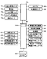
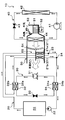
- the vehicle air conditioner 10 includes a water circulation circuit 20, a heat transport refrigeration cycle apparatus 30, a cooling refrigeration cycle apparatus 40, an indoor air conditioning unit 50, an air conditioning control apparatus 60, and the like.
- the water circulation circuit 20 is a circuit that circulates engine cooling water to heat the blown air.
- an antifreeze containing ethylene glycol aqueous solution or the like can be employed.
- the water circulation circuit 20 includes a heater core 21, a water circulation pump 22, a water passage 32 b of the heat-dissipating water-refrigerant heat exchanger 32 of the heat transport refrigeration cycle apparatus 30 described later, and a water passage of the evaporating water-refrigerant heat exchanger 34. 34b etc. are arranged.
- the heater core 21 is disposed in a casing 51 of an indoor air conditioning unit 50, which will be described later, and heat for heating the heated air by exchanging heat between the cooling water heated by the waste heat of the engine EG and the blown air. It is an exchanger.
- a water passage 32b outlet side of the heat radiation water-refrigerant heat exchanger 32 is connected to the cooling water inlet side of the heater core 21, and a water passage of the evaporating water-refrigerant heat exchanger 34 is connected to the cooling water outlet side of the heater core 21. 34b inlet side is connected.
- the water circulation pump 22 is an electric type which sucks the cooling water flowing out from the water passage 34b of the evaporating water-refrigerant heat exchanger 34 on the downstream side of the heater core 21 and pumps it to the cooling water flow path formed in the engine EG. This is a water pump.
- the water circulation pump 22 has its rotational speed (water pressure feeding capacity) controlled by a control signal output from the engine control device 70.
- the cooling water is supplied from the water circulation pump 22 ⁇ the cooling water flow path formed in the engine EG ⁇ the water passage 32 b of the radiating water-refrigerant heat exchanger 32 ⁇ the heater core 21.
- the water passage 34b of the evaporating water-refrigerant heat exchanger 34 ⁇ the water circulation pump 22 is circulated in this order.
- the broken-line arrow shown around the water circulation circuit 20 in the overall configuration diagram of FIG. 1 indicates the flow direction of the cooling water.
- the cooling water flowing through the cooling water flow path from the cooling water outlet side of the engine EG to the cooling water inlet side of the heater core 21 is the upstream cooling described in the claims.
- the cooling water flowing through the cooling water flow path from the cooling water outlet side of the heater core 21 to the cooling water inlet side of the engine EG corresponds to the downstream cooling water described in the claims. Yes.
- a radiator a cooling water bypass passage, a thermostat valve, and the like (not shown) are arranged in the water circulation circuit 20 of the present embodiment.
- the radiator is a heat dissipation heat exchanger that cools the cooling water by exchanging heat between the cooling water and outdoor air (outside air), and is connected in parallel to at least the heater core 21.
- the cooling water bypass passage is a passage through which the cooling water flows by bypassing the radiator.
- the cooling water circuit that flows the cooling water from the cooling water circuit that flows into the radiator to the cooling water bypass passage It is the cooling water circuit switching device which switches to.
- the thermostat valve switches the cooling water circuit as described above, so that, as will be described later, the temperature of the cooling water when the engine EG is operating is a predetermined reference temperature range (this embodiment). In this case, the temperature is generally maintained within 85 ° C. to 95 ° C.).
- the engine EG itself has a temperature equal to or higher than a reference warm-up temperature KTw (specifically, 50 ° C.) regardless of the running state. Warm-up control for intermittently operating the EG is performed. Therefore, in the present embodiment, even when the engine EG does not need to output the driving force for traveling, the temperature of the engine EG itself is maintained at the reference warm-up temperature KTw or higher.
- KTw specifically, 50 ° C.
- the refrigeration cycle apparatus 30 for heat transport is a heat transport section that moves the heat of the cooling water from the low temperature side to the high temperature side in the water circulation circuit 20. More specifically, the heat transport refrigeration cycle apparatus 30 includes a heat transport compressor 31, a heat radiation water-refrigerant heat exchanger 32, a heat transport fixed throttle 33, and an evaporation water-refrigerant heat exchanger 34. This is a compression refrigeration cycle.
- the heat transport compressor 31 compresses and discharges the refrigerant in the heat transport refrigeration cycle apparatus 30 and is an electric compressor that drives a fixed capacity compression mechanism with a fixed discharge capacity by an electric motor.
- various compression mechanisms such as a scroll type compression mechanism and a vane type compression mechanism can be adopted as the fixed capacity type compression mechanism.
- the rotation speed of the electric motor is controlled by a control signal output from the air conditioning control device 60, and either an AC motor or a DC motor may be adopted. And the refrigerant
- the outlet of the heat transport compressor 31 is connected to the inlet side of the refrigerant passage 32 a of the water-refrigerant heat exchanger 32 for heat radiation.
- the heat-dissipating water-refrigerant heat exchanger 32 includes a refrigerant passage 32a through which the high-pressure refrigerant discharged from the heat transport compressor 31 is circulated, and a water passage through which upstream-side cooling water is circulated among the cooling water circulated through the water circulation circuit 20. 32b. And the high-pressure refrigerant
- a water passage 32b is arranged on the outer periphery of the refrigerant passage 32a to exchange heat between the refrigerant and the cooling water, or the refrigerant is circulated as the refrigerant passage 32a.
- the heat-dissipating water-refrigerant heat exchanger 32 a counter flow type heat exchange in which the flow direction of the refrigerant flowing through the refrigerant passage 32a and the flow direction of the hot water flowing through the water passage 32b are opposite flows.
- a vessel is used as the heat-dissipating water-refrigerant heat exchanger 32.
- the heat transport fixed throttle 33 is a heat transport decompression device that decompresses the refrigerant flowing out of the coolant passage 32a.
- a nozzle, an orifice, a capillary tube or the like having a fixed throttle opening can be used as the fixed throttle 33 for heat transport.
- a refrigerant passage 34 a inlet side of the evaporating water-refrigerant heat exchanger 34 is connected to the outlet side of the heat transport fixed throttle 33.
- the evaporating water-refrigerant heat exchanger 34 is water that circulates the downstream side cooling water among the refrigerant passage 34 a that circulates the low-pressure refrigerant decompressed by the fixed throttle 33 for heat transport and the cooling water that circulates in the water circulation circuit 20. It has a passage 34b. And the low-pressure refrigerant
- an evaporating water-refrigerant heat exchanger 34 one having the same configuration as that of the radiating water-refrigerant heat exchanger 32 can be employed.
- the outlet side of the refrigerant passage 34 a of the evaporating water-refrigerant heat exchanger 34 is connected to the suction port side of the heat transport compressor 31.
- the heat absorbed from the downstream cooling water when the refrigerant evaporates in the evaporating water-refrigerant heat exchanger 34 is cooled upstream in the heat radiating water-refrigerant heat exchanger 32. Can dissipate heat to water.
- the cooling refrigeration cycle apparatus 40 is a vapor compression refrigeration cycle for cooling the blown air, and includes a cooling compressor 41, a radiator 42, a cooling expansion valve 43, and an evaporator 44. is doing.
- the cooling compressor 41 compresses and discharges the refrigerant in the cooling refrigeration cycle apparatus 40, and its basic configuration is the same as that of the heat transport compressor 31.
- the cooling compressor 41 has a larger discharge capacity than the heat transport compressor 31.
- the refrigerant inlet side of the radiator 42 is connected to the discharge port of the cooling compressor 41.
- the radiator 42 is disposed on the vehicle front side in the engine room, and exchanges heat between the high-pressure refrigerant discharged from the cooling compressor 41 and outside air (outside air) blown from a blower fan (not shown). This is a heat exchanger for heat dissipation that cools and condenses the high-pressure refrigerant.
- the blower fan is an electric blower in which the rotation speed (the amount of blown air) is controlled by a control voltage output from the air conditioning control device 60.
- the inlet side of the cooling expansion valve 43 is connected to the refrigerant outlet side of the radiator 42.
- the cooling expansion valve 43 is a cooling decompression device that decompresses the refrigerant flowing out of the radiator 42.
- the cooling expansion valve 43 has a temperature sensing unit that detects the degree of superheat of the evaporator 44 outlet-side refrigerant based on the temperature and pressure of the evaporator 44 outlet-side refrigerant, and the degree of superheat of the evaporator 44 outlet-side refrigerant is This is a temperature type expansion valve that adjusts the throttle opening by a mechanical mechanism so as to be within a predetermined reference range.
- the refrigerant inlet side of the evaporator 44 is connected to the outlet side of the cooling expansion valve 43.
- the evaporator 44 is disposed in the casing 51 of the indoor air conditioning unit 50 and exchanges heat between the low-pressure refrigerant decompressed by the cooling expansion valve 43 and the blown air, evaporates the low-pressure refrigerant, and exhibits an endothermic effect. This is an endothermic heat exchanger.
- the refrigerant outlet side of the evaporator 44 is connected to the suction port side of the compressor 11.
- the indoor air conditioning unit 50 is configured integrally with various devices for blowing out the temperature-adjusted blown air into the vehicle interior, and is disposed inside the instrument panel (instrument panel) at the forefront of the vehicle interior. ing. More specifically, the indoor air conditioning unit 50 is configured by housing a blower 52, an evaporator 44 of the cooling refrigeration cycle apparatus 40, a heater core 21 of the water circulation circuit 20, and the like in a casing 51 that forms an outer shell thereof. Yes.
- the casing 51 forms an air passage for blown air that is blown into the passenger compartment, and is formed of a resin (for example, polypropylene) having a certain degree of elasticity and excellent strength.
- An inside / outside air switching device 53 as an inside / outside air switching device for switching and introducing the inside air (vehicle compartment air) and the outside air (vehicle compartment outside air) into the casing 51 is arranged on the most upstream side of the blast air flow in the casing 51. ing.
- the inside / outside air switching device 53 continuously adjusts the opening area of the inside air introduction port through which the inside air is introduced into the casing 51 and the outside air introduction port through which the outside air is introduced by the inside / outside air switching door, so that the air volume of the inside air and the air volume of the outside air are adjusted.
- the air volume ratio is continuously changed.
- the inside / outside air switching door is driven by an electric actuator for the inside / outside air switching door, and the operation of this electric actuator is controlled by a control signal output from the air conditioning control device 60.
- a blower (blower) 52 for blowing the air sucked through the inside / outside air switching device 53 toward the vehicle interior is arranged.
- the blower 52 is an electric blower that drives a centrifugal multiblade fan (sirocco fan) with an electric motor, and the number of rotations (the amount of blown air) is controlled by a control voltage output from the air conditioning control device 60.
- the evaporator 44 and the heater core 21 are arranged in this order with respect to the flow of the blown air on the downstream side of the blower air flow of the blower 52. That is, the evaporator 44 is disposed upstream of the blower air flow with respect to the heater core 21. Further, in the casing 51, a cold air bypass passage 55 is formed in which the blown air that has passed through the evaporator 44 bypasses the heater core 21 and flows downstream.
- An air mix door 54 that adjusts the air volume ratio with the air volume that passes the air is disposed.
- a mixing space for mixing the blown air heated by the heater core 21 and the blown air that has passed through the cold air bypass passage 55 is provided. Furthermore, the opening hole which blows off the ventilation air (air conditioning wind) mixed in the mixing space to the vehicle interior which is an air-conditioning object space is arrange
- the opening hole includes a face opening hole that blows air-conditioned air toward the upper body of the passenger in the passenger compartment, a foot opening hole that blows air-conditioned air toward the feet of the passenger, and an inner surface of the front window glass of the vehicle.
- a defroster opening hole (both not shown) for blowing the conditioned air toward is provided.
- the air flow downstream of the face opening hole, foot opening hole and defroster opening hole is respectively connected to the face air outlet, foot air outlet and defroster air outlet provided in the vehicle interior via ducts forming air passages. It is connected to an outlet (both not shown).
- the air mix door 54 adjusts the air volume ratio between the air volume that passes through the heater core 21 and the air volume that passes through the cold air bypass passage 55, thereby adjusting the temperature of the conditioned air mixed in the mixing space.
- the temperature of the blast air (air conditioned air) blown out from the air outlet into the vehicle compartment is adjusted.
- the air mix door 54 constitutes a temperature adjustment device that adjusts the temperature of the conditioned air blown into the vehicle interior.
- the air mix door 54 is driven by an electric actuator for driving the air mix door, and the operation of this electric actuator is controlled by a control signal output from the air conditioning control device 60.
- a face door for adjusting the opening area of the face opening hole a foot door for adjusting the opening area of the foot opening hole, and a defroster opening, respectively.
- a defroster door (both not shown) for adjusting the opening area of the hole is disposed.
- blower outlet mode door that switches the blower outlet mode, and for driving the blower outlet mode door via a link mechanism or the like (not shown). It is connected to the electric actuator and is rotated in conjunction with it. The operation of this electric actuator is also controlled by a control signal output from the air conditioning controller 60.
- the face air outlet, the face air outlet and the foot air outlet which opens the face air outlet fully and blows air from the face air outlet toward the upper body of the passenger in the passenger compartment.
- the bi-level mode that opens both of the air outlets and blows air toward the upper body and feet of passengers in the passenger compartment, fully opens the foot outlet and opens the defroster outlet by a small opening, and mainly draws air from the foot outlet.
- the defroster mode in which the occupant manually operates the blowing mode changeover switch provided on the operation panel to fully open the defroster outlet and blow out air from the defroster outlet to the inner surface of the front windshield of the vehicle.
- the engine control device 70 and the air conditioning control device 60 are configured by a known microcomputer including a CPU, a ROM, a RAM, and the like and peripheral circuits thereof. Then, various operations and processes are performed based on the control program stored in the ROM to control the operation of various devices connected to the output side.
- various engine constituent devices that constitute the engine EG are connected to the output side of the engine control device 70. Specifically, a starter for starting the engine EG, a drive circuit for a fuel injection valve (injector) for supplying fuel to the engine EG, and the like are connected.
- a cooling water temperature sensor 71 for detecting the cooling water temperature Tw flowing out of the engine EG, a voltmeter 72 for detecting the battery voltage VB, and an accelerator opening Acc are detected.
- An engine opening sensor 73, an engine speed sensor 74 for detecting the engine speed Ne, and a vehicle speed sensor 75 for detecting the vehicle speed Vv are connected.
- the air-conditioning control device 60 On the output side of the air-conditioning control device 60, there are a heat transport compressor 31, a cooling compressor 41, a blower 52, an inside / outside air switching door, an air mix door, and an electric actuator for driving to drive the outlet mode door.
- Various air conditioning control devices are connected.
- the air-conditioning control device 60 is configured integrally with a control device that controls various air-conditioning control devices connected to the output side of the air-conditioning control device 60.
- Software constitutes a control device for controlling the operation of each air conditioning control device.
- the configuration for controlling the operation of the heat transport refrigeration cycle apparatus 30 constitutes the heat transport control unit 60a.
- an inside air sensor 61 that detects the vehicle interior temperature Tr
- an outside air sensor 62 that detects the outside air temperature Ta
- a solar radiation sensor 63 that detects the amount of solar radiation As in the vehicle interior
- an evaporator 44 A sensor group for air conditioning control, such as an evaporator temperature sensor 64 (evaporator temperature detector) for detecting the refrigerant evaporation temperature (evaporator temperature) Tefin, an air temperature sensor 65 for detecting the air temperature TAV blown into the passenger compartment. Is connected.
- an operation panel 80 disposed near the instrument panel in the front of the passenger compartment is connected to the input side of the air conditioning control device 60, and operation signals of various air conditioning operation switches provided on the operation panel 80 are sent to the air conditioning control device. 60.
- an operation switch for requesting operation or stop of the vehicle air conditioner 1 a temperature setting switch for setting the set temperature Tset in the vehicle interior, an operation mode changeover switch for setting the operation mode, An air outlet mode changeover switch, an air volume setting switch of the blower 52, and the like are provided.
- the engine control device 70 and the air conditioning control device 60 of the present embodiment are configured to be communicable with each other by being electrically connected to each other. Thereby, based on the detection signal or operation signal input into one control apparatus, the other control apparatus can also control the operation
- the engine control device 70 calculates the traveling load of the vehicle based on the detection signals of the above-described engine control sensor groups 71 to 75, and the engine EG is turned on according to the traveling load. Activate or deactivate. Furthermore, the engine control device 70 operates the water circulation pump 22 so as to exhibit a predetermined water pressure feeding capability when the vehicle is started.
- the cooling water circulating in the water circulation circuit 20 absorbs the waste heat of the engine EG and cools the engine EG as it flows through the cooling water flow path formed in the engine EG.
- the thermostat valve of the water circulation circuit 20 when the temperature of the cooling water passing through the thermostat valve of the water circulation circuit 20 is equal to or lower than the reference switching temperature, the thermostat valve switches to the cooling water circuit that flows the cooling water to the cooling water bypass passage side.
- the waste heat of the engine EG that has absorbed heat is not radiated to the atmosphere by the radiator.
- the thermostat valve switches the cooling water circuit so that the temperature of the cooling water and the engine EG itself is maintained within a predetermined reference temperature range (approximately 85 ° C. to 95 ° C. in this embodiment). Is done.
- the coolant temperature Tw detected by the coolant temperature sensor 71 even when the engine EG does not need to be operated to output the driving force for vehicle travel. Is controlled to operate the engine EG so as to be higher than the reference warm-up temperature KTw (in this embodiment, 50 ° C.).
- the reference warm-up temperature KTw it is desirable to set the reference warm-up temperature KTw to a temperature higher than 50 ° C. in order to suppress an increase in friction loss at the time of restart and malfunction of the exhaust gas purification catalyst.
- the reference warm-up temperature KTw is set to a temperature higher than 50 ° C., the frequency of operating the engine EG increases when it is not necessary to operate the engine EG in order to output the driving force for traveling the vehicle. End up.
- the warm-up control according to the present embodiment it is possible to suppress the increase in friction loss at the time of restart and the malfunction of the exhaust gas purifying catalyst, and to set the reference warm-up as a temperature that does not unnecessarily deteriorate the vehicle fuel consumption.
- the machine temperature KTw is set to 50 ° C.
- the operation of the vehicle air conditioner 10 will be described.
- a cooling mode in which the cooled blown air is blown into the vehicle interior based on an operation signal of the operation mode changeover switch of the operation panel 80, a cooling mode in which the cooled blown air is blown into the vehicle interior, and a heating in which the heated blown air is blown into the vehicle interior.
- the mode and the dehumidifying and heating mode in which the blown air that has been cooled and dehumidified is reheated and blown out into the passenger compartment can be switched. The operation in each operation mode will be described below.
- Cooling mode The cooling mode is executed when the operation switch of the operation panel 80 is turned on (ON) and the cooling mode is selected by the operation mode switch.
- the air conditioning control device 60 reads the detection signals of the air conditioning control sensor groups 61 to 65 and the operation signals of the operation panel 80 described above. Then, a target blowing temperature TAO that is a target temperature of air blown into the vehicle interior is calculated based on the read detection signal and operation signal values.
- the target blowing temperature TAO is calculated by the following formula F1.
- TAO Kset ⁇ Tset ⁇ Kr ⁇ Tr ⁇ Kam ⁇ Tam ⁇ Ks ⁇ As + C (F1)
- Tr is the vehicle interior temperature (internal air temperature) detected by the internal air sensor 61
- Tam is the external air temperature detected by the external air sensor 62
- I the amount of solar radiation detected by the solar radiation sensor 63.
- Kset, Kr, Kam, Ks are control gains
- C is a correction constant.
- control signals to be output to various air conditioning control devices connected to the output side of the air conditioning control device 60 are determined.
- control signal output to the electric motor of the cooling compressor 41 of the cooling refrigeration cycle apparatus 40 is determined as follows.
- the target evaporator outlet temperature TEO of the evaporator 44 is determined with reference to a control map stored in the air conditioning controller 60 in advance. This target evaporator outlet temperature TEO is determined so as to decrease as the target outlet temperature TAO decreases so that the outlet air temperature TAV approaches the target outlet temperature TAO.
- the evaporator temperature Tefin approaches the target evaporator outlet temperature TEO using a feedback control method.
- a control signal output to the electric motor of the cooling compressor 41 is determined.
- control voltage (blower motor voltage) output to the electric motor of the blower 52 is determined so as to be substantially maximum in the extremely low temperature range (maximum cooling range) and the extremely high temperature range (maximum heating range) of the TAO. Further, as the TAO moves from the extremely low temperature region or the extremely high temperature region to the intermediate temperature region, the blower motor voltage is determined to be gradually decreased from the substantially maximum value.
- the air mix door 54 closes the air passage on the heater core 21 side, and the total air volume of the blown air after passing through the evaporator 44 is the cold air bypass passage 55. Decide to pass.
- the outside air mode in which outside air is introduced is basically given priority.
- TAO is in a very low temperature range and high cooling performance is desired. It decides to become a shy mode to introduce shyness into.
- the air outlet mode As for the control signal output to the electric actuator for the air outlet mode door, as the TAO rises from the low temperature range to the high temperature range, the air outlet mode is switched from foot mode to bi-level mode to face mode. To be determined. Accordingly, the face mode is mainly selected in the summer, the bi-level mode is mainly selected in the spring and autumn, and the foot mode is mainly selected in the winter.
- control signal output to the electric motor of the heat transport compressor 31 of the heat transport refrigeration cycle apparatus 30 is determined so as to stop the operation of the heat transport compressor 31.
- control signals determined as described above are output to various air conditioning control devices.
- the above detection signal and operation signal are read at every predetermined control cycle ⁇ the target blowing temperature TAO is calculated ⁇ the operating states of various air conditioning control devices
- a control routine such as decision-> output of control voltage and control signal is repeated. Such a control routine is repeated in the other operation modes.
- the blown air (cold air) cooled by the evaporator 44 of the cooling refrigeration cycle apparatus 40 is blown out into the vehicle interior via the cold air bypass passage 55, the mixing space, and each outlet. .
- the passenger compartment is cooled.
- Heating mode is executed when the heating mode is selected by the operation mode changeover switch in a state where the operation switch of the operation panel 80 is turned on (ON).
- the air conditioning control device 60 In the heating mode, as in the cooling mode, the air conditioning control device 60 generates control signals or control voltages to be output to various air conditioning control devices based on the target blowing temperature TAO and the detection signals of the air conditioning control sensor groups 61 to 65. decide.
- control signal output to the electric motor of the cooling compressor 41 is determined so as to stop the operation of the cooling compressor 41. Further, the control signal output to the electric actuator for the air mix door 54 is determined so that the blown air temperature TAV detected by the blown air temperature sensor 65 approaches the target blown temperature TAO using a feedback control method.
- Other air conditioning control devices are the same as in the cooling mode.
- the temperature adjustment is performed so that the blown air (hot air) heated by the heater core 21 and the blown air that has passed through the cold air bypass passage 55 are mixed in the mixing space so as to approach the target blowing temperature TAO.
- the conditioned air thus blown out into the passenger compartment through each outlet. Thereby, the vehicle interior is heated.
- (C) Dehumidifying heating mode The heating mode is executed when the dehumidifying heating mode is selected by the operation mode changeover switch in a state where the operation switch of the operation panel 80 is turned on (ON).
- the air conditioning control device 60 outputs control signals to various air conditioning control devices based on the target blowing temperature TAO and the detection signals of the air conditioning control sensor groups 61 to 65, as in the cooling mode and the heating mode. Determine the control voltage and the like.
- control signal output to the electric motor of the cooling compressor 41 is determined such that the evaporator temperature Tefin is equal to or higher than a predetermined reference evaporator temperature (specifically, 1 ° C.).
- the reference evaporator temperature is determined so that frost formation does not occur in the evaporator 44.
- Other air conditioning control devices are the same as in the heating mode.
- the blown air (cold air) cooled and dehumidified by the evaporator 44 is reheated by the heater core 21.
- the reheated blown air (warm air) and the blown air (cold air) that has passed through the cold air bypass passage 55 are mixed in the mixing space, thereby adjusting the temperature of the conditioned air so as to approach the target blowing temperature TAO. Is blown out into the passenger compartment through each outlet. Thereby, dehumidification heating in the passenger compartment is performed.
- the vehicle air conditioner 10 of the present embodiment it is possible to perform cooling, heating, and dehumidifying heating in the passenger compartment.
- the blown air is heated using the cooling water of the engine EG as a heat source during heating of the vehicle interior and during dehumidifying heating.
- the temperature of the cooling water flowing into the heater core 21 does not rise above the temperature required to perform heating or dehumidifying heating in the vehicle interior, The blown air that is generated cannot be sufficiently heated, and the passenger's feeling of heating is deteriorated.
- the engine EG is operated so that the coolant temperature Tw becomes the reference warm-up temperature KTw (specifically, 50 ° C.). Yes. For this reason, if heating of a vehicle interior or dehumidification heating is performed during execution of warm-up control, the passenger's feeling of heating may be deteriorated.
- the heating determination temperature KHTw of the present embodiment is set to 60 ° C. as the cooling water temperature necessary to sufficiently heat the blown air so as not to deteriorate the passenger's feeling of heating.
- the heat transport control unit 60a of the air conditioning control device 60 operates the compressor 31 for heat transport of the refrigeration cycle device 30 for heat transport. More specifically, the heat transport control unit 60a is determined so that the temperature of the upstream cooling water flowing into the heater core 21 is equal to or higher than the heating determination temperature KHTw with respect to the electric motor of the heat transport compressor 31. Output a control signal.
- the high-pressure refrigerant discharged from the heat transport compressor 31 flows into the refrigerant passage 32a of the heat-dissipating water-refrigerant heat exchanger 32 and flows upstream through the water passage 32b. Heat exchange with cooling water to dissipate heat. Thereby, the temperature of the upstream side cooling water flowing into the heater core 21 is heated to the heating determination temperature KHTw or higher.
- the refrigerant that has flowed out of the refrigerant passage 32 a of the heat-dissipating water-refrigerant heat exchanger 32 is decompressed by the heat transport fixed throttle 33.
- the low-pressure refrigerant decompressed by the heat transport fixed throttle 33 flows into the refrigerant passage 34a of the evaporating water-refrigerant heat exchanger 34, evaporates by exchanging heat with the downstream cooling water flowing through the water passage 34b. Thereby, the temperature of the downstream side cooling water flowing into the engine EG is lower than that in the heating mode or the dehumidifying heating mode.
- the refrigerant that has flowed out of the refrigerant passage 34a of the evaporating water-refrigerant heat exchanger 34 is sucked into the heat transport compressor 31 and compressed again.
- the temperature of the upstream side cooling water flowing into the heater core 21 can be heated to the heating determination temperature KHTw or higher by the water for radiating water-refrigerant heat exchanger 32. Therefore, the blower air can be sufficiently heated by the heater core 21, and the deterioration of the passenger's feeling of heating can be suppressed.
- the engine EG is not operated to increase the temperature of the upstream side cooling water flowing into the heater core 21 when it is not necessary to output the driving force for traveling the vehicle. Even if the fuel is consumed to operate the refrigeration cycle apparatus 30 for heat transportation, it is possible to comprehensively suppress the deterioration of the vehicle fuel consumption.
- a normal vehicle air conditioner hereinafter referred to as a comparative air conditioner
- a comparative air conditioner applied to a hybrid vehicle in which the reference warm-up temperature KTw in the warm-up control is set to 60 ° C. This will be described in comparison with the heating mode or the dehumidifying heating mode.
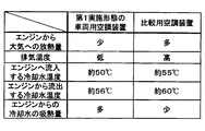
- the temperature of the engine EG itself during warm-up control is higher than that of the hybrid vehicle of the present embodiment. For this reason, the temperature difference between the temperature of the engine EG itself and the outside air temperature increases, and the amount of heat released from the engine EG itself to the atmosphere increases as shown in the chart of FIG. Furthermore, since the temperature of the exhaust gas also rises, the amount of heat released to the atmosphere via the exhaust gas increases.
- the downstream-side cooling water and the engine EG flowing into the engine EG are compared to the heating mode or the dehumidifying heating mode of the comparative air conditioner.
- the temperature of the upstream cooling water flowing out from the tank becomes low. For this reason, the temperature difference between the engine EG and the cooling water increases, and the amount of heat absorbed by the cooling water from the engine EG increases.
- the heat generated when the engine EG consumes fuel is higher than in the heating mode or the dehumidifying heating mode of the comparative air conditioner.
- the ratio of heat that is thrown away into the atmosphere can be reduced, and the waste heat of the engine EG can be efficiently absorbed into the cooling water.
- the cooling water temperature at the cooling water outlet of the engine EG relative to the cooling water temperature at the cooling water inlet of the engine EG. Can be made larger than the heating mode or the dehumidifying heating mode of the comparative air conditioner.
- the heat absorbed efficiently can be used for heating or dehumidifying heating in the passenger compartment, and the vehicle fuel consumption is deteriorated overall. Can be suppressed.
- the vehicle air conditioner 10 of the present embodiment it is possible to achieve both suppression of deterioration in vehicle fuel consumption and suppression of deterioration in passenger heating feeling.
- the vehicle air conditioner 10 of the present embodiment it is possible to suppress the deterioration of the passenger's feeling of heating without incurring deterioration of the vehicle fuel consumption.
- the amount of electric power necessary for operating the heat transport compressor 31 of the heat transport refrigeration cycle apparatus 30 during the strong heating mode or the strong dehumidifying heating mode is determined by operating the engine EG. It has been found that the amount of surplus power stored in the battery is less than the amount of surplus power stored during the running conditions.
- the engine EG is hardly operated only to operate the heat transport refrigeration cycle apparatus 30, and even if the heat transport refrigeration cycle apparatus 30 is operated, the vehicle fuel consumption is hardly deteriorated. .
- surplus power stored in the battery can be effectively utilized for heating or dehumidifying heating in the vehicle interior.
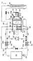
- the heater core 21 of the present embodiment has a plurality (two in the present embodiment) of heat exchange portions 21a and 21b arranged in series with the flow of the blown air.
- the windward side heat exchange unit 21a those arranged on the upstream side of the blast air flow are referred to as the windward side heat exchange unit 21a, and those arranged on the downstream side of the blast air flow are referred to as the leeward side heat exchange unit 21b.
- the windward side heat exchange unit 21a those arranged on the upstream side of the blast air flow
- the leeward side heat exchange unit 21b those arranged on the downstream side of the blast air flow
- the branch portion 23 that branches the flow of the upstream side cooling water flowing out from the engine EG, and the flow of the cooling water that flows out from the windward side heat exchanging portion 21a and the leeward side heat exchanging portion.
- a merging portion 24 for merging the flow of cooling water that has flowed out of 21b is disposed.
- the branch portion 23 is configured by a three-way joint having three inflow / outflow ports, and one of the three inflow / outflow ports is a cooling water inflow port and the remaining two are cooling water outflow ports.
- a three-way joint may be formed by joining pipes having different pipe diameters, or may be formed by providing a plurality of cooling water passages in a metal block or a resin block.
- One cooling water outlet of the branch portion 23 is connected to the inlet side of the water passage 32b of the water for radiating water-refrigerant heat exchanger 32, and on the outlet side of the water passage 32b of the water for radiating water-refrigerant heat exchanger 32, The cooling water inlet side of the leeward side heat exchanging portion 21b is connected. Further, the other cooling water outlet of the branch part 23 is connected to the cooling water inlet side of the windward heat exchange part 21a.
- the upstream side cooling water that has flowed out from one cooling water outlet of the branch portion 23 is used as the heat radiation water-refrigerant heat exchanger 32. After being heated at, it is made to flow into the leeward side heat exchanging part 21b and to allow the upstream side cooling water flowing out from the other cooling water outlet of the branching part 23 to flow into the leeward side heat exchanging part 21a.
- the passage sectional area of one cooling water outlet side of the cooling water passages in the branching portion 23 is formed smaller than the passage sectional area of the other cooling water outlet side. Therefore, the leeward flow rate Q2 of the cooling water flowing through the leeward heat exchange unit 21b is smaller than the leeward flow rate Q1 of the cooling water flowing through the windward heat exchange unit 21a. More specifically, the leeward flow rate Q2 of the present embodiment is about 1/15 of the leeward flow rate Q1.
- the confluence 24 is composed of a three-way joint similar to the branch 23, and two of the three inflow / outflow ports are cooling water inflow ports, and the remaining one is a cooling water outflow port.
- An inlet side of the water passage 34 b of the evaporating water-refrigerant heat exchanger 34 is connected to the cooling water outlet of the junction 24.
- the refrigerant of the heat transport refrigeration cycle apparatus 30 flows out of the windward heat exchange unit 21a in the evaporating water-refrigerant heat exchanger 34. It absorbs and evaporates the heat of the downstream cooling water, which is a combination of the cooling water flow and the cooling water flow that has flowed out of the leeward heat exchange section 21b.
- the heater core 21 has two heat exchanging parts, the windward side heat exchanging part 21a and the leeward side heat exchanging part 21b, and the cooling water flowing out from the engine EG is used as wind. Cooling water that has flowed into the upper heat exchanging portion 21a and has flowed out of the water passage 32b of the heat-dissipating water-refrigerant heat exchanger 32 is caused to flow into the leeward heat exchanging portion 21b.
- the temperature of the upstream cooling water flowing into the leeward heat exchange unit 21b is higher than the temperature of the upstream cooling water flowing into the leeward heat exchange unit 21a. According to this, in both heat exchanging parts 21a and 21b, a temperature difference between cooling water and blown air can be secured, and blown air can be efficiently heated.
- the leeward flow rate Q2 of the cooling water flowing through the leeward heat exchange unit 21b is less than the leeward flow rate Q1 of the cooling water flowing through the windward heat exchange unit 21a. Therefore, the flow rate of the cooling water flowing through the water passage 32b of the heat-dissipating water-refrigerant heat exchanger 32 can be reduced compared to the first embodiment.
- the heat absorption amount that the cooling water absorbs heat from the high-pressure refrigerant in the heat radiation water-refrigerant heat exchanger 32 that is, the heat radiation amount that the refrigerant radiates heat to the cooling water in the heat radiation water-refrigerant heat exchanger 32 decreases. Therefore, the cycle balance in the heat transport refrigeration cycle apparatus 30 changes so as to increase the refrigerant pressure (refrigerant condensation temperature) in the refrigerant passage 32a of the heat-dissipating water-refrigerant heat exchanger 32.
- the heat radiation water-refrigerant heat exchanger 32 is heated without increasing the rotational speed of the heat transport compressor 31 compared to the first embodiment.
- the temperature of the cooling water can be increased.
- the blower air can be sufficiently heated by the heater core 21, and the deterioration of the passenger's feeling of heating can be suppressed more reliably.
- the flow of the cooling water and the leeward heat flowing out from the windward heat exchange unit 21a to the refrigerant of the refrigeration cycle device 30 for heat transport is carried.
- the heat which the downstream side cooling water which merged with the flow of the cooling water which flowed out from exchange part 21b has absorbed heat.
- the heat absorption amount does not become insufficient as in the case of absorbing the heat of the cooling water that has flowed out of any one of the heat exchange sections, and the heater core in the radiating water-refrigerant heat exchanger 32 It is possible to reliably heat the temperature of the upstream-side cooling water flowing into 21 to the heating determination temperature KHTw or higher.
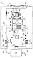
- the heater core 21 of the present embodiment includes the windward side heat exchange unit 21a and the leeward side heat exchange unit 21b similar to those of the second embodiment.
- the branch part 23 is arrange
- One cooling water outlet of the branch portion 23 of the present embodiment is connected to the inlet side of the water passage 32b of the radiating water-refrigerant heat exchanger 32, and the outlet of the water passage 32b of the radiating water-refrigerant heat exchanger 32 is connected.
- the cooling water inlet side of the leeward side heat exchanging portion 21b is connected to the side.
- one cooling water inlet of the merging portion 24 is connected to the other cooling water outlet of the branching portion 23, and the other cooling of the merging portion 24 is connected to the cooling water outlet side of the leeward side heat exchanging portion 21b. A water inlet is connected.
- the upstream side cooling water that has flowed out from one cooling water outlet of the branch portion 23 is used as the heat radiation water-refrigerant heat exchanger 32.
- the cooling water that has flowed from the cooling water outlet that flows out from the other cooling water outlet of the branch portion 23 is merged with the cooling water that has flowed out from the leeward heat exchange portion 21b. Yes.
- cooling, heating, and dehumidifying heating in the passenger compartment can be performed. Further, when the cooling water temperature Tw is equal to or lower than the heating determination temperature KHTw, by performing the operation in the strong heating mode and the strong dehumidifying heating mode, the passenger's feeling of heating is not caused without deteriorating the vehicle fuel consumption. Can be prevented.
- the heater core 21 since the heater core 21 has the two heat exchange parts 21a and 21b arranged in series with respect to the flow of blowing air, it is the same as in the second embodiment. The effect of can be obtained.
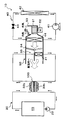
- the basic configuration of the compressor 91 of the present embodiment is the same as the heat transport compressor 31 and the cooling compressor 41. Further, in the present embodiment, a compressor having a larger discharge capacity than the cooling compressor 41 is employed as the compressor 91.
- the cooling water inlet side of the three-way flow rate adjustment valve 92 is connected to the discharge port of the cooling compressor 41.
- the basic configuration of the compressor 91 is the same as that of the heat transport compressor 31 and the cooling compressor 41. Further, in the present embodiment, a compressor having a larger discharge capacity than the cooling compressor 41 is employed as the compressor 91.
- the cooling water inlet side of the three-way flow rate adjustment valve 92 is connected to the discharge port of the cooling compressor 41.
- the three-type flow rate adjusting valve 92 is an electric type that adjusts the flow rate ratio between the refrigerant flow rate flowing into the heat radiating water-refrigerant heat exchanger 32 and the refrigerant flow rate flowing into the radiator 42 among the refrigerant discharged from the compressor 91. This is a flow regulating valve. The operation of the three-type flow rate adjusting valve 92 is controlled by a control signal output from the air conditioning control device 60.
- the three-system flow rate adjusting valve 92 of the present embodiment can cause the entire flow rate of the refrigerant discharged from the compressor 91 to flow into the radiator 42 or flow into the heat radiating water-refrigerant heat exchanger 32. Therefore, the three-system flow rate adjustment valve 92 of the present embodiment also has a function as a refrigerant circuit switching device that switches the refrigerant circuit.
- One refrigerant outlet of the three-mode flow rate adjusting valve 92 is connected to a suction port of the compressor 91 via a heat-dissipating water-refrigerant heat exchanger 32, a heat transport fixed throttle 33, and an evaporating water-refrigerant heat exchanger 34.
- the side is connected.
- the refrigerant path from the outlet side of the refrigerant passage 34a of the evaporating water-refrigerant heat exchanger 34 to the inlet side of the compressor 91 is connected to the compressor from the outlet side of the refrigerant passage 34a of the evaporating water-refrigerant heat exchanger 34.
- a check valve 93a for heat transport that only allows the refrigerant to flow to the suction port side of 91 is disposed.
- the other refrigerant outlet of the three-type flow rate adjusting valve 92 is connected to the suction port side of the compressor 91 via the radiator 42, the cooling expansion valve 43, and the evaporator 44. Further, the cooling passage that allows only the refrigerant to flow from the refrigerant outlet side of the evaporator 44 to the suction port side of the compressor 91 in the refrigerant path from the refrigerant outlet side of the evaporator 44 to the suction port side of the compressor 91.
- a check valve 93b is arranged.
- Other configurations are the same as those of the second embodiment.
- the air conditioning control device 60 operates the compressor 91 in the same manner as in the second embodiment, and the total flow rate of the refrigerant discharged from the compressor 91 is changed to the radiator 42.
- the operation of the three-type flow rate adjusting valve 92 is controlled so as to flow into.
- the air conditioning control device 60 stops the compressor 91. Further, in the dehumidifying and heating mode, the air conditioning control device 60 operates the compressor 91 in the same manner as in the second embodiment so that the total flow rate of the refrigerant discharged from the compressor 91 flows into the radiator 42. The operation of the flow rate adjustment valve 92 is controlled.
- the air conditioning control device 60 operates the compressor 91 so as to exhibit the refrigerant discharge capacity equivalent to that in the heating mode and the dehumidifying heating mode. Further, the operation of the three-type flow rate adjustment valve 92 is performed so that a part of the refrigerant discharged from the compressor 91 flows into the radiator 42 and the remaining refrigerant flows into the refrigerant passage 32a of the water-refrigerant heat exchanger 32 for heat radiation. To control. Other operations are the same as those in the second embodiment.
- the vehicle air conditioner 10 of this embodiment operates in exactly the same way as in the second embodiment, and can obtain the same effect. Furthermore, in this embodiment, since the compressor for heat transport 31 and the compressor for cooling 41 are used in common and one compressor 91 is employed, the vehicle air conditioner 10 as a whole can be reduced in size and manufacturing cost. Can be reduced.
- the inlet side of the refrigerant passage 32a of the heat-dissipating water-refrigerant heat exchanger 32 is connected to the discharge port side of the compressor 91, and the refrigerant of the radiator 42 is connected to the outlet side of the refrigerant passage 32a.
- the inlet side is connected.
- a refrigerant branching portion 94 that branches the flow of the refrigerant flowing out of the radiator 42 is disposed on the refrigerant outlet side of the radiator 42.
- the inlet side of the compressor 91 is connected to one of the refrigerant outlets of the refrigerant branch portion 94 via the heat transport fixed throttle 33, the evaporating water-refrigerant heat exchanger 34, and the heat transport check valve 93a.
- the other refrigerant outlet of the refrigerant branch portion 94 is connected to the suction port side of the compressor 91 via the cooling expansion valve 43, the evaporator 44, and the cooling check valve 93b.
- Other configurations are the same as those of the second embodiment.
- the operation of the vehicle air conditioner of the present embodiment having the above configuration will be described.
- the refrigerant discharged from the compressor 91 flows into the refrigerant passage 32a of the water-refrigerant heat exchanger 32 for heat radiation when the compressor 91 is operated, the operation in the strong heating mode and the dehumidifying heating mode is performed. Is not executed.
- the air conditioning control device 60 operates the compressor 91 as in the fourth embodiment.
- the air conditioning control device 60 stops the compressor 91.
- the air conditioning control device 60 operates the compressor 91 so as to exhibit the refrigerant discharge capacity equivalent to that of the fourth embodiment.
- Other operations are the same as those in the fourth embodiment.
- the cooling water and the refrigerant discharged from the compressor 91 exchange heat in the heat-dissipating water-refrigerant heat exchanger 32, but the air mix door 54 is on the heater core 21 side. Since the air passage is closed, the vehicle interior can be cooled as in the second embodiment. In the heating mode, the passenger compartment can be heated just as in the second embodiment.
- the cooling water heated to the heating determination temperature KHTw (specifically, 60 ° C.) or higher in the heat radiating water-refrigerant heat exchanger 32 is caused to flow into the leeward heat exchange unit 21b. Therefore, as in the second embodiment, it is possible to suppress the deterioration of the passenger's feeling of heating without causing deterioration of the vehicle fuel consumption.
- the entire vehicle air conditioner 10 is similar to the fourth embodiment. Thus, it is possible to reduce the size and the manufacturing cost.
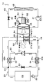
- the Peltier device 100 is used as a heat transport part. Adopted.
- the Peltier element 100 is a plate-like semiconductor element that utilizes the Peltier effect, and is supplied with electric power from the air-conditioning control device 60, whereby the heat absorbed by one surface can be dissipated to the other surface.
- the water passage 34b for circulating the downstream side cooling water is joined to one surface of the Peltier element 100, and the water passage 32b for circulating the upstream side cooling water is joined to the other surface.
- the heat absorbed from the downstream side cooling water flowing through the water passage 34b can be radiated to the upstream side cooling water flowing through the water passage 32b.
- the heat transport control unit 60a of this embodiment controls the operation of the Peltier element 100. Specifically, the heat transport control unit 60a of the present embodiment supplies power to the Peltier element 100 in the strong heating mode or the strong dehumidifying heating mode. Other configurations and operations are the same as those in the first embodiment. Therefore, also in the vehicle air conditioner 10 of the present embodiment, the same effect as in the first embodiment can be obtained.
- the heater core 21 has been described as having two heat exchanging parts, the windward side heat exchanging part 21a and the leeward side heat exchanging part 21b. As long as it has at least two heat exchange units arranged in series with respect to the air flow, it may have three or more heat exchange units.
- the leeward flow rate Q2 of the cooling water flowing through the leeward heat exchange unit 21b is greater than the leeward flow rate Q1 of the cooling water flowing through the windward heat exchange unit 21a.
- the windward flow volume Q1 and the leeward flow volume Q2 may be equivalent.
- the elements and devices disclosed in each of the above embodiments may be appropriately combined within a feasible range.
- the heat transport compressor 31 of the heat transport refrigeration cycle apparatus 30 and the cooling compressor 41 of the cooling refrigeration cycle apparatus 40 described in the first and third embodiments are used as a common compressor 91
- the fourth As described in the fifth embodiment, the heat transport refrigeration cycle apparatus 30 and the cooling refrigeration cycle apparatus 40 may be integrally configured as one refrigeration cycle apparatus 90.
- the Peltier element 100 may be employed as the heat transport unit.
Abstract
車両走行用の駆動力を出力するエンジン(内燃機関)EGの冷却水を循環させる水循環回路(20)に、冷却水と車室内へ送風される送風空気とを熱交換させて送風空気を加熱するヒータコア(21)を配置する。さらに、エンジンEGから流出した冷却水の温度が低下した際に、エンジンEGを作動させることなく、ヒータコア(21)より下流側の下流側冷却水の有する熱を吸熱してヒータコア(21)より上流側の上流側冷却水へ放熱する熱輸送部としての熱輸送用冷凍サイクル装置(30)を作動させて、ヒータコア(21)へ流入する冷却水の温度を車室内の暖房を行うために必要な温度となるまで上昇させる。
Description
本出願は、当該開示内容が参照によって本出願に組み込まれた、2014年5月13日に出願された日本特許出願2014-099635を基にしている。
本開示は、車両走行用の駆動力を出力する内燃機関の冷却水を熱源として車室内の暖房を行う車両用空調装置に関する。
従来、車両走行用の駆動力を出力するエンジン(内燃機関)の冷却水と車室内へ送風される送風空気とを熱交換させて送風空気を加熱し、加熱された送風空気を車室内へ吹き出すことによって、車室内の暖房を行う車両用空調装置が知られている。さらに、特許文献1には、この種の車両用空調装置であって、エンジンを間欠的に作動させる車両に適用されたものが開示されている。
ここで、エンジンを間欠的に作動させる車両としては、例えば、車両燃費の向上のために、エンジンがアイドリング状態となった際にエンジンを停止させるアイドルストップ車両や、車両走行用の駆動力をエンジンおよび電動モータの双方から得ることのできるハイブリッド車両等がある。
このようなエンジンを間欠的に作動させる車両では、エンジンの停止時には冷却水の温度が上昇しないので、冷却水の温度が車室内の適切な暖房を行うために必要な温度(具体的には、55℃以上の温度)よりも低下してしまうことがある。そのため、暖房時に送風空気を充分に加熱することができず、乗員の暖房感を悪化させてしまうことがある。
これに対して、特許文献1の車両用空調装置では、暖房時に車室内へ吹き出される送風空気の温度が予め定めた基準温度以下となった際に、エンジンが車両走行用の駆動力を出力する必要がなくても、エンジン制御装置に対してエンジンの作動要求を行っている。これにより、エンジンを作動させて、冷却水の温度が車室内の暖房を行うために必要な温度よりも低下してしまうことを抑制し、乗員の暖房感の悪化を抑制している。
しかしながら、特許文献1の車両用空調装置のように、エンジンが車両走行用の駆動力を出力する必要がないときに、冷却水の温度を上昇させるためにエンジンを作動させることは、車両燃費を悪化させてしまう原因となる。
本開示は、上記点に鑑み、車両走行用の駆動力を出力する内燃機関の冷却水を熱源として車室内の暖房を行う車両用空調装置において、車両燃費の悪化の抑制および乗員の暖房感の悪化の抑制の双方を両立させることを目的とする。
本開示の一つの特徴例の車両用空調装置は、車両走行用の駆動力を出力する内燃機関を冷却する冷却水を循環させる水循環回路を備え、水循環回路には、内燃機関にて加熱された冷却水と車室内へ送風される送風空気とを熱交換させて送風空気を加熱する加熱用熱交換器が配置される。
さらに、水循環回路のうち、加熱用熱交換器の冷却水出口側から内燃機関の冷却水入口側へ至る冷却水流路を流れる下流側冷却水の有する熱を吸熱し、下流側冷却水から吸熱した熱を、水循環回路のうち、内燃機関の冷却水出口側から加熱用熱交換器の冷却水入口側へ至る冷却水流路を流通する上流側冷却水へ放熱する熱輸送部を備える。
これによれば、熱輸送部を備えているので、内燃機関から流出した冷却水の温度が充分に上昇していなくても、加熱用熱交換器へ流入する上流側冷却水の温度を車室内の適切な暖房を行うために必要な温度となるまで上昇させることができる。
従って、加熱用熱交換器にて車室内へ送風される送風空気を充分に加熱することができ、乗員の暖房感の悪化を抑制することができる。
さらに、車両走行用の駆動力を出力する必要がないとき等に、上流側冷却水の温度を上昇させるために内燃機関を作動させないので、熱輸送部を作動させるために燃料を消費したとしても、総合的に車両燃費の悪化を抑制できる。
より詳細には、熱輸送部が下流側冷却水の有する熱を吸熱するので、加熱用熱交換器から流出した下流側冷却水を直接内燃機関へ流入させる場合に対して、内燃機関へ流入させる下流側冷却水の温度を低下させることができる。これにより、内燃機関へ流入した冷却水と内燃機関との温度差を拡大することができ、冷却水に内燃機関の廃熱を効率的に吸熱させることができる。
従って、熱輸送部を作動させることによって燃料を消費したとしても、効率的に吸熱した熱を車室内の暖房に利用することができるので、総合的に車両燃費の悪化を抑制することができる。
つまり、上記特徴例によれば、内燃機関の冷却水を熱源として車室内の暖房を行う車両用空調装置において、車両燃費の悪化の抑制および乗員の暖房感の悪化の抑制の双方を両立させることができる。換言すると、車両燃費の悪化を招くことなく、乗員の暖房感の悪化を抑制可能な車両用空調装置を提供することができる。
なお、上述した車両燃費とは、内燃機関が消費した燃料の量に対する走行距離の比であって、単位燃料消費量あたりの走行距離と表現することができる。従って、車両走行用の駆動力を出力する必要がないときに、冷却水の温度を上昇させるために内燃機関を作動させると車両燃費は悪化することになる。
また、上記特徴例の車両用空調装置において、加熱用熱交換器は、送風空気の流れに対して直列に配置された複数の熱交換部を有し、複数の熱交換部として、送風空気の流れ方向最下流側に配置された風下側熱交換部、および風下側熱交換部よりも送風空気の流れ方向上流側に配置された風上側熱交換部が設けられており、水循環回路は、熱輸送部にて加熱された上流側冷却水を、風下側熱交換部へ流入させるように構成されていてもよい。
これによれば、風下側熱交換部へ流入する上流側冷却水の温度を風上側熱交換部へ流入する上流側冷却水の温度よりも高くすることができる。従って、双方の熱交換部において、冷却水と送風空気との温度差を確保することができ、冷却水と送風空気との効率的な熱交換を行うことができる。
また、上記特徴例の車両用空調装置において、具体的に、熱輸送部は、蒸気圧縮式の冷凍サイクル装置で構成されていてもよいし、ペルチェ素子で構成されていてもよい。
(第1実施形態)
図1~図4により、本開示の第1実施形態を説明する。本実施形態では、本開示に係る車両用空調装置10を、内燃機関(エンジン)EGおよび走行用電動モータの双方から車両走行用の駆動力を得るハイブリッド車両に適用している。
図1~図4により、本開示の第1実施形態を説明する。本実施形態では、本開示に係る車両用空調装置10を、内燃機関(エンジン)EGおよび走行用電動モータの双方から車両走行用の駆動力を得るハイブリッド車両に適用している。
本実施形態のハイブリッド車両は、車両の走行負荷に応じてエンジンEGを間欠的に作動させて、エンジンEGおよび走行用電動モータの双方から駆動力を得て走行する走行モード(HV走行モード)や、エンジンEGを停止させて走行用電動モータのみから駆動力を得て走行する走行モード(EV走行モード)等を切り替えることができる。
そして、このような走行モードの切り替えによって、エンジンのみから車両走行用の駆動力を得る通常の車両よりも車両燃費を向上させている。なお、車両燃費とは、エンジンが消費した燃料の量に対する車両の走行距離の比であって、単位燃料消費量あたりの走行距離と表現することができる。
さらに、本実施形態のハイブリッド車両では、エンジンEGから出力された駆動力を、車両を走行させるためだけでなく、図示しない発電機を駆動するためにも用いている。この発電機にて発電された電力は、リチウムイオン電池等からなる蓄電装置(バッテリ)に蓄えられ、走行用電動モータや車両用空調装置10を構成する各種電動機器等に供給される。
また、本実施形態のハイブリッド車両では、エンジンEGとして、後述するエンジン制御装置70から出力される制御信号によって、その作動が制御されるガソリンエンジンを採用している。エンジンEGは作動時に発熱を伴う車載機器なので、本実施形態の車両用空調装置10では、エンジンEGの廃熱を利用して、車室内へ送風される送風空気を加熱している。
次に、本実施形態の車両用空調装置10の詳細構成について説明する。この車両用空調装置10は、水循環回路20、熱輸送用冷凍サイクル装置30、冷却用冷凍サイクル装置40、室内空調ユニット50、および空調制御装置60等を備えている。
まず、水循環回路20は、送風空気を加熱するためにエンジンの冷却水を循環させる回路である。この冷却水としては、エチレングリコール水溶液を含む不凍液等を採用することができる。また、水循環回路20には、ヒータコア21、水循環ポンプ22、後述する熱輸送用冷凍サイクル装置30の放熱用水-冷媒熱交換器32の水通路32b、および蒸発用水-冷媒熱交換器34の水通路34b等が配置されている。
ヒータコア21は、後述する室内空調ユニット50のケーシング51内に配置されており、エンジンEGの廃熱等によって加熱された冷却水と送風空気とを熱交換させて、送風空気を加熱する加熱用熱交換器である。ヒータコア21の冷却水入口側には、放熱用水-冷媒熱交換器32の水通路32b出口側が接続されており、ヒータコア21の冷却水出口側には、蒸発用水-冷媒熱交換器34の水通路34b入口側が接続されている。
水循環ポンプ22は、ヒータコア21の下流側であって蒸発用水-冷媒熱交換器34の水通路34bから流出した冷却水を吸入して、エンジンEG内に形成された冷却水流路へ圧送する電動式の水ポンプである。この水循環ポンプ22は、エンジン制御装置70から出力される制御信号によって回転数(水圧送能力)が制御される。
そして、エンジン制御装置70が、水循環ポンプ22を作動させると、冷却水は、水循環ポンプ22→エンジンEG内に形成された冷却水流路→放熱用水-冷媒熱交換器32の水通路32b→ヒータコア21→蒸発用水-冷媒熱交換器34の水通路34b→水循環ポンプ22の順で循環する。なお、図1の全体構成図の水循環回路20の周囲に示す破線矢印は、冷却水の流れ方向を示している。
従って、本実施形態では、水循環回路20のうち、エンジンEGの冷却水出口側からヒータコア21の冷却水入口側へ至る冷却水流路を流れる冷却水が、特許請求の範囲に記載された上流側冷却水に対応している。また、水循環回路20のうち、ヒータコア21の冷却水出口側からエンジンEGの冷却水入口側へ至る冷却水流路を流れる冷却水が、特許請求の範囲に記載された下流側冷却水に対応している。
さらに、本実施形態の水循環回路20には、図示しないラジエータ、冷却水バイパス通路、およびサーモスタット弁等が配置されている。ラジエータは、冷却水と室外空気(外気)とを熱交換させて冷却水を冷却する放熱用の熱交換器であって、少なくともヒータコア21に対して並列的に接続されている。
冷却水バイパス通路は、ラジエータを迂回させて冷却水を流す通路である。サーモスタット弁は、内部を流通する冷却水の温度が基準切替温度(本実施形態では、90℃)以下になると、冷却水をラジエータへ流入させる冷却水回路から冷却水バイパス通路へ流入させる冷却水回路へ切り替える冷却水回路切替装置である。
本実施形態では、サーモスタット弁が上記の如く冷却水回路の切り替えを行うことによって、後述するように、エンジンEGが作動している際の冷却水の温度が予め定めた基準温度範囲(本実施形態では、概ね85℃~95℃)内に維持される。
さらに、本実施形態のエンジン制御装置70では、後述するように、走行状態とは無関係に、エンジンEG自体の温度が基準暖機温度KTw(具体的には、50℃)以上となるようにエンジンEGを間欠的に作動させる暖機制御を行っている。従って、本実施形態では、エンジンEGが走行用の駆動力を出力する必要が無いときであっても、エンジンEG自体の温度が、基準暖機温度KTw以上に維持される。
次に、熱輸送用冷凍サイクル装置30は、水循環回路20において、冷却水の有する熱を低温側から高温側へ移動させる熱輸送部である。より具体的には、熱輸送用冷凍サイクル装置30は、熱輸送用圧縮機31、放熱用水-冷媒熱交換器32、熱輸送用固定絞り33、および蒸発用水-冷媒熱交換器34を有する蒸気圧縮式の冷凍サイクルである。
熱輸送用圧縮機31は、熱輸送用冷凍サイクル装置30において、冷媒を圧縮して吐出するもので、吐出容量が固定された固定容量型圧縮機構を電動モータにて駆動する電動圧縮機である。この固定容量型圧縮機構としては、具体的に、スクロール型圧縮機構、ベーン型圧縮機構等の各種圧縮機構を採用することができる。
電動モータは、空調制御装置60から出力される制御信号によって、その回転数が制御されるもので、交流モータ、直流モータのいずれの形式を採用してもよい。そして、この回転数制御によって、圧縮機11の冷媒吐出能力が変更される。熱輸送用圧縮機31の吐出口には、放熱用水-冷媒熱交換器32の冷媒通路32a入口側が接続されている。
放熱用水-冷媒熱交換器32は、熱輸送用圧縮機31から吐出された高圧冷媒を流通させる冷媒通路32a、および水循環回路20を循環する冷却水のうち、上流側冷却水を流通させる水通路32bを有している。そして、冷媒通路32aを流通する高圧冷媒と水通路32bを流通する上流側冷却水とを熱交換させて、上流側冷却水を加熱する機能を果たす。
このような放熱用水-冷媒熱交換器32の具体的構成としては、冷媒通路32aの外周に水通路32bを配置して冷媒と冷却水とを熱交換させる構成や、冷媒通路32aとして冷媒を流通させる蛇行状のチューブあるいは複数本のチューブを採用し、隣り合うチューブ間に水通路32bを形成し、さらに、冷媒と冷却水との間の熱交換を促進するコルゲートフィンやプレートフィンを設ける構成等を採用することができる。
さらに、本実施形態では、放熱用水-冷媒熱交換器32として、冷媒通路32aを流通する冷媒の流れ方向と水通路32bを流通する給湯水の流れ方向が対向流となる対向流型の熱交換器を採用している。放熱用水-冷媒熱交換器32の冷媒通路32aの出口側には、熱輸送用固定絞り33の入口側が接続されている。
熱輸送用固定絞り33は、冷媒通路32aから流出した冷媒を減圧させる熱輸送用減圧装置である。熱輸送用固定絞り33としては、絞り開度が固定されたノズル、オリフィス、キャピラリチューブ等を採用することができる。熱輸送用固定絞り33の出口側には、蒸発用水-冷媒熱交換器34の冷媒通路34a入口側が接続されている。
蒸発用水-冷媒熱交換器34は、熱輸送用固定絞り33にて減圧された低圧冷媒を流通させる冷媒通路34a、および水循環回路20を循環する冷却水のうち、下流側冷却水を流通させる水通路34bを有している。そして、冷媒通路34aを流通する低圧冷媒と水通路34bを流通する下流側冷却水とを熱交換させて、低圧冷媒を蒸発させて吸熱作用を発揮させる機能を果たす。
このような蒸発用水-冷媒熱交換器34としては、放熱用水-冷媒熱交換器32と同様の構成のものを採用することができる。蒸発用水-冷媒熱交換器34の冷媒通路34aの出口側には、熱輸送用圧縮機31の吸入口側が接続されている。
従って、熱輸送用冷凍サイクル装置30では、蒸発用水-冷媒熱交換器34にて冷媒が蒸発する際に下流側冷却水から吸熱した熱を、放熱用水-冷媒熱交換器32にて上流側冷却水へ放熱することができる。
次に、冷却用冷凍サイクル装置40は、送風空気を冷却するための蒸気圧縮式の冷凍サイクルであって、冷却用圧縮機41、放熱器42、冷却用膨張弁43、および蒸発器44を有している。
冷却用圧縮機41は、冷却用冷凍サイクル装置40において、冷媒を圧縮して吐出するもので、その基本的構成は、熱輸送用圧縮機31と同様である。なお、本実施形態では、冷却用圧縮機41として、熱輸送用圧縮機31よりも吐出容量の大きいものを採用している。冷却用圧縮機41の吐出口には、放熱器42の冷媒入口側が接続されている。
放熱器42は、エンジンルーム内の車両前方側に配置されており、冷却用圧縮機41から吐出された高圧冷媒と図示しない送風ファンから送風された車室外空気(外気)とを熱交換させて、高圧冷媒を冷却して凝縮させる放熱用熱交換器である。送風ファンは、空調制御装置60から出力される制御電圧によって回転数(送風空気量)が制御される電動送風機である。放熱器42の冷媒出口側には、冷却用膨張弁43の入口側が接続されている。
冷却用膨張弁43は、放熱器42から流出した冷媒を減圧させる冷却用減圧装置である。この冷却用膨張弁43は、蒸発器44出口側冷媒の温度および圧力に基づいて蒸発器44出口側冷媒の過熱度を検知する感温部を有し、蒸発器44出口側冷媒の過熱度が予め定めた基準範囲内となるように機械的機構によって絞り開度を調整する温度式膨張弁である。冷却用膨張弁43の出口側には、蒸発器44の冷媒入口側が接続されている。
蒸発器44は、室内空調ユニット50のケーシング51内に配置されており、冷却用膨張弁43にて減圧された低圧冷媒と送風空気とを熱交換させ、低圧冷媒を蒸発させて吸熱作用を発揮させる吸熱用熱交換器である。蒸発器44の冷媒出口側には、圧縮機11の吸入口側が接続されている。
次に、室内空調ユニット50は、温度調整された送風空気を車室内へ吹き出すための各種機器を一体的に構成したもので、車室内最前部の計器盤(インストルメントパネル)の内側に配置されている。より具体的には、室内空調ユニット50は、その外殻を形成するケーシング51内に送風機52、冷却用冷凍サイクル装置40の蒸発器44、水循環回路20のヒータコア21等を収容して構成されている。
ケーシング51は、車室内に送風される送風空気の空気通路を形成するもので、ある程度の弾性を有し、強度的にも優れた樹脂(例えば、ポリプロピレン)にて成形されている。このケーシング51内の送風空気流れ最上流側には、ケーシング51内へ内気(車室内空気)と外気(車室外空気)とを切替導入する内外気切替装置としての内外気切替装置53が配置されている。
内外気切替装置53は、ケーシング51内へ内気を導入させる内気導入口および外気を導入させる外気導入口の開口面積を、内外気切替ドアによって連続的に調整して、内気の風量と外気の風量との風量割合を連続的に変化させるものである。内外気切替ドアは、内外気切替ドア用の電動アクチュエータによって駆動され、この電動アクチュエータは、空調制御装置60から出力される制御信号によって、その作動が制御される。
内外気切替装置53の送風空気流れ下流側には、内外気切替装置53を介して吸入した空気を車室内へ向けて送風する送風機(ブロワ)52が配置されている。この送風機52は、遠心多翼ファン(シロッコファン)を電動モータにて駆動する電動送風機であって、空調制御装置60から出力される制御電圧によって回転数(送風量)が制御される。
送風機52の送風空気流れ下流側には、蒸発器44およびヒータコア21が、送風空気の流れに対して、この順に配置されている。つまり、蒸発器44は、ヒータコア21に対して、送風空気流れ上流側に配置されている。また、ケーシング51内には、蒸発器44を通過した送風空気を、ヒータコア21を迂回させて下流側へ流す冷風バイパス通路55が形成されている。
さらに、蒸発器44の送風空気流れ下流側であって、かつ、ヒータコア21の送風空気流れ上流側には、蒸発器44通過後の送風空気のうち、ヒータコア21を通過させる風量と冷風バイパス通路55を通過させる風量との風量割合を調整するエアミックスドア54が配置されている。
また、ヒータコア21の送風空気流れ下流側には、ヒータコア21にて加熱された送風空気と冷風バイパス通路55を通過した送風空気とを混合させる混合空間が設けられている。さらに、ケーシング51の送風空気流れ最下流部には、混合空間にて混合された送風空気(空調風)を、空調対象空間である車室内へ吹き出す開口穴が配置されている。
具体的には、この開口穴としては、車室内の乗員の上半身に向けて空調風を吹き出すフェイス開口穴、乗員の足元に向けて空調風を吹き出すフット開口穴、および車両前面窓ガラス内側面に向けて空調風を吹き出すデフロスタ開口穴(いずれも図示せず)が設けられている。
さらに、これらのフェイス開口穴、フット開口穴およびデフロスタ開口穴の送風空気流れ下流側は、それぞれ空気通路を形成するダクトを介して、車室内に設けられたフェイス吹出口、フット吹出口およびデフロスタ吹出口(いずれも図示せず)に接続されている。
従って、エアミックスドア54が、ヒータコア21を通過させる風量と冷風バイパス通路55を通過させる風量との風量割合を調整することによって、混合空間にて混合される空調風の温度が調整されて、各吹出口から車室内へ吹き出される送風空気(空調風)の温度が調整されることになる。
つまり、エアミックスドア54は、車室内へ送風される空調風の温度を調整する温度調整装置を構成している。エアミックスドア54は、エアミックスドア駆動用の電動アクチュエータによって駆動され、この電動アクチュエータは、空調制御装置60から出力される制御信号によって、その作動が制御される。
また、フェイス開口穴、フット開口穴、およびデフロスタ開口穴の送風空気流れ上流側には、それぞれ、フェイス開口穴の開口面積を調整するフェイスドア、フット開口穴の開口面積を調整するフットドア、デフロスタ開口穴の開口面積を調整するデフロスタドア(いずれも図示せず)が配置されている。
これらのフェイスドア、フットドア、デフロスタドアは、吹出口モードを切り替える吹出口モード切替装置(吹出口モードドア)を構成するものであって、図示しないリンク機構等を介して、吹出口モードドア駆動用の電動アクチュエータに連結されて連動して回転操作される。この電動アクチュエータも、空調制御装置60から出力される制御信号によって、その作動が制御される。
吹出口モード切替装置によって切り替えられる吹出口モードとしては、具体的に、フェイス吹出口を全開してフェイス吹出口から車室内乗員の上半身に向けて空気を吹き出すフェイスモード、フェイス吹出口とフット吹出口の両方を開口して車室内乗員の上半身と足元に向けて空気を吹き出すバイレベルモード、フット吹出口を全開するとともにデフロスタ吹出口を小開度だけ開口して、フット吹出口から主に空気を吹き出すフットモード、およびフット吹出口およびデフロスタ吹出口を同程度開口して、フット吹出口およびデフロスタ吹出口の双方から空気を吹き出すフットデフロスタモードがある。
さらに、乗員が操作パネルに設けられた吹出モード切替スイッチをマニュアル操作することによって、デフロスタ吹出口を全開してデフロスタ吹出口から車両フロント窓ガラス内面に空気を吹き出すデフロスタモードとすることもできる。
次に、図2のブロック図を用いて、本実施形態の電気制御部について説明する。エンジン制御装置70および空調制御装置60は、CPU、ROMおよびRAM等を含む周知のマイクロコンピュータとその周辺回路から構成される。そして、このROM内に記憶された制御プログラムに基づいて各種演算、処理を行って、出力側に接続された各種機器の作動を制御する。
エンジン制御装置70の出力側には、上述した水循環ポンプ22の他に、エンジンEGを構成する各種エンジン構成機器等が接続されている。具体的には、エンジンEGを始動させるスタータ、エンジンEGに燃料を供給する燃料噴射弁(インジェクタ)の駆動回路等が接続されている。
また、エンジン制御装置70の入力側には、エンジンEGから流出した冷却水の冷却水温度Twを検出する冷却水温度センサ71、バッテリの電圧VBを検出する電圧計72、アクセル開度Accを検出するアクセル開度センサ73、エンジン回転数Neを検出するエンジン回転数センサ74、車速Vvを検出する車速センサ75等のエンジン制御用センサ群が接続されている。
空調制御装置60の出力側には、熱輸送用圧縮機31、冷却用圧縮機41、送風機52、内外気切替ドア、エアミックスドア、および吹出口モードドアを駆動する駆動用の電動アクチュエータ等の各種空調制御機器が接続されている。
なお、空調制御装置60は、その出力側に接続された各種空調制御機器を制御する制御装置が一体に構成されたものであるが、それぞれの空調制御機器の作動を制御する構成(ハードウェアおよびソフトウェア)が、それぞれの空調制御機器の作動を制御する制御装置を構成している。
例えば、本実施形態では、熱輸送用冷凍サイクル装置30(具体的には、熱輸送用圧縮機31)の作動を制御する構成が、熱輸送制御部60aを構成している。もちろん、それぞれの空調制御機器の作動を制御する制御部や熱輸送制御部60a等を空調制御装置60に対して別体の制御装置で構成してもよい。
また、空調制御装置60の入力側には、車室内温度Trを検出する内気センサ61、外気温Taを検出する外気センサ62、車室内の日射量Asを検出する日射センサ63、蒸発器44における冷媒蒸発温度(蒸発器温度)Tefinを検出する蒸発器温度センサ64(蒸発器温度検出部)、車室内に吹き出される吹出空気温度TAVを検出する吹出空気温度センサ65等の空調制御用センサ群が接続されている。
さらに、空調制御装置60の入力側には、車室内前部の計器盤付近に配置された操作パネル80が接続され、この操作パネル80に設けられた各種空調操作スイッチの操作信号が空調制御装置60へ入力される。
各種空調操作スイッチとしては、具体的に、車両用空調装置1の作動あるいは停止を要求する作動スイッチ、車室内の設定温度Tsetを設定する温度設定スイッチ、運転モードを切替設定する運転モード切替スイッチ、吹出口モード切替スイッチ、送風機52の風量設定スイッチ等が設けられている。
なお、本実施形態のエンジン制御装置70および空調制御装置60は、互いに電気的に接続されて、通信可能に構成されている。これにより、一方の制御装置に入力された検出信号あるいは操作信号に基づいて、他方の制御装置が出力側に接続された各種機器の作動を制御することもできる。従って、エンジン制御装置70および空調制御装置60を1つの制御装置として一体的に構成してもよい。
次に、上記構成における本実施形態の作動について説明する。まず、エンジン制御装置70が実行する基本的な制御処理について説明する。
車両スタートスイッチが投入されて車両が起動すると、エンジン制御装置70は、上述のエンジン制御用センサ群71~75の検出信号に基づいて車両の走行負荷を算出し、走行負荷に応じてエンジンEGを作動あるいは停止させる。さらに、エンジン制御装置70は、車両の起動とともに、水循環ポンプ22を所定の水圧送能力を発揮するように作動させる。
従って、エンジンEGの作動時には、水循環回路20を循環する冷却水が、エンジンEG内に形成された冷却水流路を流通する際に、エンジンEGの廃熱を吸熱してエンジンEGを冷却する。
そして、水循環回路20のサーモスタット弁を通過する冷却水の温度が基準切替温度(本実施形態では、90℃)よりも高くなっている場合には、サーモスタット弁が冷却水をラジエータ側へ流す冷却水回路に切り替えるので、冷却水に吸熱されたエンジンEGの廃熱は、ラジエータにて大気へ放熱される。
一方、水循環回路20のサーモスタット弁を通過する冷却水の温度が基準切替温度以下になっている場合には、サーモスタット弁が冷却水を冷却水バイパス通路側に流す冷却水回路に切り替えるので、冷却水に吸熱されたエンジンEGの廃熱が、ラジエータにて大気へ放熱されることはない。
従って、エンジンEGの作動時には、サーモスタット弁が冷却水回路を切り替えることによって、冷却水およびエンジンEG自体の温度が予め定めた基準温度範囲(本実施形態では、概ね85℃~95℃)内に維持される。
その結果、エンジンEG自体の温度が過度に上昇して、エンジンEGがオーバーヒートしてしまうことを防止することができる。さらに、エンジンEG自体の温度が過度に低下して、エンジンオイルの粘度増加によるフリクションロスが増加してしまうことや、排気ガスの温度低下による排気ガス浄化用触媒の作動不良が生じてしまうことを抑制することができる。
また、エンジンEGの停止時には、エンジンEG自体が発熱しないだけでなく、エンジンEG自体からの放熱等により、冷却水およびエンジンEG自体の温度が過度に低下してしまうおそれがある。
そこで、本実施形態のエンジン制御装置70では、車両走行用の駆動力を出力させるためにエンジンEGを作動させる必要がないときであっても、冷却水温度センサ71によって検出された冷却水温度Twが基準暖機温度KTw(本実施形態では、50℃)よりも高くなるようにエンジンEGを作動させる暖機制御を行う。
より具体的には、この暖機制御では、冷却水温度Twが基準暖機温度KTwよりも低くなった際に、冷却水温度Twが基準暖機温度KTwよりも2℃程度高くなるまで、エンジンEGを作動させる。これにより、冷却水温度Twは、基準暖機温度KTw以上に維持される。
その結果、エンジンEG自体の温度が過度に低下して、エンジンEGを再始動させる際にフリクションロスが増加してしまうことや、排気ガス浄化用触媒の作動不良が生じてしまうことを抑制することができる。
ここで、再始動時のフリクションロスの増加や排気ガス浄化用触媒の作動不良を抑制するためには、基準暖機温度KTwを50℃よりも高い温度に設定しておくことが望ましい。ところが、基準暖機温度KTwを50℃よりも高い温度に設定すると、車両走行用の駆動力を出力させるためにエンジンEGを作動させる必要がないときに、エンジンEGを作動させる頻度が増加してしまう。
このようなエンジンEGの作動頻度の増加は、車両燃費を悪化させる原因となる。そこで、本実施形態の暖機制御では、再始動時のフリクションロスの増加や排気ガス浄化用触媒の作動不良の抑制を図ることができるとともに、車両燃費を不必要に悪化させない温度として、基準暖機温度KTwを50℃に設定している。
次に、車両用空調装置10の作動を説明する。本実施形態の車両用空調装置10では、操作パネル80の運転モード切替スイッチの操作信号に基づいて、冷却された送風空気を車室内へ吹き出す冷房モード、加熱された送風空気を車室内へ吹き出す暖房モード、さらに、冷却されて除湿された送風空気を再加熱して車室内へ吹き出す除湿暖房モードを切り替えることができる。以下に各運転モードにおける作動を説明する。
(a)冷房モード
冷房モードは、操作パネル80の作動スイッチが投入(ON)された状態で、運転モード切替スイッチによって冷房モードが選択されている際に実行される。冷房モードでは、空調制御装置60が、上述の空調制御用センサ群61~65の検出信号および操作パネル80の操作信号を読み込む。そして、読み込まれた検出信号および操作信号の値に基づいて車室内へ吹き出す空気の目標温度である目標吹出温度TAOを算出する。
冷房モードは、操作パネル80の作動スイッチが投入(ON)された状態で、運転モード切替スイッチによって冷房モードが選択されている際に実行される。冷房モードでは、空調制御装置60が、上述の空調制御用センサ群61~65の検出信号および操作パネル80の操作信号を読み込む。そして、読み込まれた検出信号および操作信号の値に基づいて車室内へ吹き出す空気の目標温度である目標吹出温度TAOを算出する。
具体的には、目標吹出温度TAOは、以下数式F1によって算出される。
TAO=Kset×Tset-Kr×Tr-Kam×Tam-Ks×As+C…(F1)
なお、Tsetは操作パネル80の温度設定スイッチによって設定された車室内設定温度、Trは内気センサ61によって検出された車室内温度(内気温)、Tamは外気センサ62によって検出された外気温、Asは日射センサ63によって検出された日射量である。Kset、Kr、Kam、Ksは制御ゲインであり、Cは補正用の定数である。
TAO=Kset×Tset-Kr×Tr-Kam×Tam-Ks×As+C…(F1)
なお、Tsetは操作パネル80の温度設定スイッチによって設定された車室内設定温度、Trは内気センサ61によって検出された車室内温度(内気温)、Tamは外気センサ62によって検出された外気温、Asは日射センサ63によって検出された日射量である。Kset、Kr、Kam、Ksは制御ゲインであり、Cは補正用の定数である。
さらに、算出された目標吹出温度TAOおよび空調制御用センサ群61~65の検出信号に基づいて、空調制御装置60の出力側に接続された各種空調制御機器へ出力する制御信号等を決定する。
例えば、冷却用冷凍サイクル装置40の冷却用圧縮機41の電動モータに出力される制御信号については、以下のように決定される。
まず、目標吹出温度TAOに基づいて、予め空調制御装置60に記憶された制御マップを参照して、蒸発器44の目標蒸発器吹出温度TEOを決定する。この目標蒸発器吹出温度TEOは、吹出空気温度TAVが目標吹出温度TAOに近づくように、目標吹出温度TAOの低下に伴って低くなるように決定される。
そして、この目標蒸発器吹出温度TEOと蒸発器温度センサ64によって検出された蒸発器温度Tefinとの偏差に基づいて、フィードバック制御手法を用いて蒸発器温度Tefinが目標蒸発器吹出温度TEOに近づくように、冷却用圧縮機41の電動モータに出力される制御信号を決定する。
また、送風機52の電動モータに出力される制御電圧(ブロワモータ電圧)については、TAOの極低温域(最大冷房域)および極高温域(最大暖房域)で略最大値となるように決定する。さらに、TAOが極低温域あるいは極高温域から中間温度域に向かうに伴って、ブロワモータ電圧を略最大値から徐々に減少させるように決定する。
また、エアミックスドア54用の電動アクチュエータへ出力される制御信号については、エアミックスドア54がヒータコア21側の空気通路を閉塞し、蒸発器44通過後の送風空気の全風量が冷風バイパス通路55を通過するように決定する。
また、内外気切替ドア用の電動アクチュエータへ出力される制御信号については、基本的に外気を導入する外気モードが優先されるが、TAOが極低温域となって高い冷房性能を得たい場合等に内気を導入する内気モードとなるように決定する。
また、吹出口モードドア用の電動アクチュエータへ出力される制御信号については、TAOが低温域から高温域へと上昇するに伴って、吹出口モードがフットモード→バイレベルモード→フェイスモードへ順次切り替えられるように決定される。従って、夏季は主にフェイスモード、春秋季は主にバイレベルモード、そして冬季は主にフットモードが選択されることになる。
また、熱輸送用冷凍サイクル装置30の熱輸送用圧縮機31の電動モータに出力される制御信号については、熱輸送用圧縮機31の作動を停止させるように決定する。
そして、上記の如く決定された制御信号等を各種空調制御機器へ出力する。その後、操作パネルによって車両用空調装置10の作動停止が要求されるまで、所定の制御周期毎に、上述の検出信号および操作信号の読み込み→目標吹出温度TAOの算出→各種空調制御機器の作動状態決定→制御電圧および制御信号の出力といった制御ルーチンが繰り返される。なお、このような制御ルーチンの繰り返しは、他の運転モード時にも同様に行われる。
従って、冷房モードでは、冷却用冷凍サイクル装置40の蒸発器44にて冷却された送風空気(冷風)が、冷風バイパス通路55、混合空間、および各吹出口を介して、車室内へ吹き出される。これにより、車室内の冷房がなされる。
(b)暖房モード
暖房モードは、操作パネル80の作動スイッチが投入(ON)された状態で、運転モード切替スイッチによって暖房モードが選択されている際に実行される。暖房モードでは、空調制御装置60が、冷房モードと同様に、目標吹出温度TAOおよび空調制御用センサ群61~65の検出信号に基づいて、各種空調制御機器へ出力する制御信号あるいは制御電圧等を決定する。
暖房モードは、操作パネル80の作動スイッチが投入(ON)された状態で、運転モード切替スイッチによって暖房モードが選択されている際に実行される。暖房モードでは、空調制御装置60が、冷房モードと同様に、目標吹出温度TAOおよび空調制御用センサ群61~65の検出信号に基づいて、各種空調制御機器へ出力する制御信号あるいは制御電圧等を決定する。
例えば、冷却用圧縮機41の電動モータに出力される制御信号については、冷却用圧縮機41の作動を停止させるように決定する。また、エアミックスドア54用の電動アクチュエータへ出力される制御信号については、フィードバック制御手法を用いて吹出空気温度センサ65によって検出された吹出空気温度TAVが目標吹出温度TAOに近づくように決定する。その他の空調制御機器については、冷房モードと同様である。
従って、暖房モードでは、ヒータコア21にて加熱された送風空気(温風)と冷風バイパス通路55を通過した送風空気が混合空間にて混合されることによって、目標吹出温度TAOに近づくように温度調整された空調風が各吹出口を介して、車室内へ吹き出される。これにより、車室内の暖房がなされる。
(c)除湿暖房モード
暖房モードは、操作パネル80の作動スイッチが投入(ON)された状態で、運転モード切替スイッチによって除湿暖房モードが選択される際に実行される。除湿暖房モードでは、空調制御装置60が、冷房モードおよび暖房モードと同様に、目標吹出温度TAOおよび空調制御用センサ群61~65の検出信号に基づいて、各種空調制御機器へ出力する制御信号あるいは制御電圧等を決定する。
暖房モードは、操作パネル80の作動スイッチが投入(ON)された状態で、運転モード切替スイッチによって除湿暖房モードが選択される際に実行される。除湿暖房モードでは、空調制御装置60が、冷房モードおよび暖房モードと同様に、目標吹出温度TAOおよび空調制御用センサ群61~65の検出信号に基づいて、各種空調制御機器へ出力する制御信号あるいは制御電圧等を決定する。
例えば、冷却用圧縮機41の電動モータに出力される制御信号については、蒸発器温度Tefinが、予め定めた基準蒸発器温度(具体的には、1℃)以上となるように決定する。なお、基準蒸発器温度は、蒸発器44に着霜が生じないように定められている。その他の空調制御機器について、暖房モードと同様である。
従って、暖房モードでは、蒸発器44にて冷却されて除湿された送風空気(冷風)がヒータコア21にて再加熱される。そして、再加熱された送風空気(温風)と冷風バイパス通路55を通過した送風空気(冷風)が混合空間にて混合されることによって、目標吹出温度TAOに近づくように温度調整された空調風が各吹出口を介して、車室内へ吹き出される。これにより、車室内の除湿暖房がなされる。
以上の如く、本実施形態の車両用空調装置10によれば、車室内の冷房、暖房、そして除湿暖房を行うことができる。
ここで、本実施形態の車両用空調装置10では、車室内の暖房時および除湿暖房時に、エンジンEGの冷却水を熱源として送風空気を加熱している。このような構成では、暖房時および除湿暖房時に、ヒータコア21へ流入させる冷却水の温度が、車室内の暖房あるいは除湿暖房を行うために必要な温度以上に上昇していないと、車室内へ吹き出される送風空気を充分に加熱することができず、乗員の暖房感が悪化してしまう。
さらに、本発明者らの検討によれば、車室内の充分な暖房あるいは除湿暖房を行うためには、ヒータコア21へ流入させる冷却水の温度を少なくとも55℃以上に昇温させておく必要があることが判っている。
ところが、本実施形態のエンジン制御装置70の暖機制御では、前述の如く、冷却水温度Twを基準暖機温度KTw(具体的には、50℃)程度となるようにエンジンEGを作動させている。このため、暖機制御の実行中に、車室内の暖房あるいは除湿暖房を行うと、乗員の暖房感が悪化してしまうおそれがある。
これに対して、暖機制御時の基準暖機温度KTwを60℃程度に設定しておく手段が考えられるものの、基準暖機温度KTwを50℃から60℃程度に上昇させてしまうと、前述の如く、エンジンEGの作動頻度が増加して車両燃費を悪化させてしまう。
そこで、本実施形態の車両用空調装置10では、暖房モード時あるいは除湿暖房モード時に冷却水温度Twが、暖房判定温度KHTw以下になっている際には、強暖房モードあるいは強除湿暖房モードでの運転を行う。本実施形態の暖房判定温度KHTwは、乗員の暖房感を悪化させないように送風空気を充分に加熱するために必要な冷却水の温度として、60℃に設定している。
強暖房モードあるいは強除湿暖房モードでは、空調制御装置60の熱輸送制御部60aが、熱輸送用冷凍サイクル装置30の熱輸送用圧縮機31を作動させる。より具体的には、熱輸送制御部60aは、熱輸送用圧縮機31の電動モータに対して、ヒータコア21へ流入する上流側冷却水の温度が暖房判定温度KHTw以上となるように決定された制御信号を出力する。
従って、強暖房モードあるいは強除湿暖房モードでは、熱輸送用圧縮機31から吐出された高圧冷媒が、放熱用水-冷媒熱交換器32の冷媒通路32aへ流入し、水通路32bを流通する上流側冷却水と熱交換して放熱する。これにより、ヒータコア21へ流入する上流側冷却水の温度が、暖房判定温度KHTw以上に加熱される。
放熱用水-冷媒熱交換器32の冷媒通路32aから流出した冷媒は、熱輸送固定絞り33にて減圧される。熱輸送用固定絞り33にて減圧された低圧冷媒は、蒸発用水-冷媒熱交換器34の冷媒通路34aへ流入し、水通路34bを流通する下流側冷却水と熱交換して蒸発する。これにより、暖房モードあるいは除湿暖房モードよりも、エンジンEGへ流入する下流側冷却水の温度が低下する。
蒸発用水-冷媒熱交換器34の冷媒通路34aから流出した冷媒は、熱輸送用圧縮機31へ吸入されて再び圧縮される。
以上の如く、強暖房モードあるいは強除湿暖房モードでは、放熱用水-冷媒熱交換器32にて、ヒータコア21へ流入させる上流側冷却水の温度を暖房判定温度KHTw以上に加熱することができる。従って、ヒータコア21にて送風空気を充分に加熱することができ、乗員の暖房感の悪化を抑制することができる。
さらに、強暖房モードあるいは強除湿暖房モードでは、車両走行用の駆動力を出力する必要がないとき等に、ヒータコア21へ流入させる上流側冷却水の温度を上昇させるためにエンジンEGを作動させないので、熱輸送用冷凍サイクル装置30を作動させるために燃料を消費したとしても、総合的に車両燃費の悪化を抑制できる。
このことを、図3、図4を用いて、暖機制御における基準暖機温度KTwが60℃に設定されたハイブリッド車両に適用された通常の車両用空調装置(以下、比較用空調装置と記載する。)の暖房モードあるいは除湿暖房モードと比較して説明する。
まず、比較用空調装置が適用されたハイブリッド車両では、本実施形態のハイブリッド車両よりも、暖機制御時におけるエンジンEG自体の温度が高くなる。このため、エンジンEG自体の温度と外気温との温度差が拡大し、図3の図表に示すように、エンジンEG自体から大気に放熱される放熱量が多くなる。さらに、排気の温度も上昇するので、排気を介して大気に放熱される放熱量も多くなる。
このことは、基準暖機温度KTwが60℃に設定されたハイブリッド車両では、本実施形態のハイブリッド車両よりも、エンジンEGが燃料を消費する際に発生させた熱のうち、大気に捨てられてしまう熱の割合が多いことを意味している。
その一方で、本実施形態の車両用空調装置10の強暖房モードあるいは強除湿暖房モードでは、比較用空調装置の暖房モードあるいは除湿暖房モードよりも、エンジンEGへ流入する下流側冷却水およびエンジンEGから流出する上流側冷却水の温度が低くなる。このため、エンジンEGと冷却水との温度差が拡大し、冷却水がエンジンEGから吸熱する吸熱量が多くなる。
つまり、本実施形態の車両用空調装置10の強暖房モードあるいは強除湿暖房モードでは、比較用空調装置の暖房モードあるいは除湿暖房モードよりも、エンジンEGが燃料を消費する際に発生させた熱のうち、大気に捨てられてしまう熱の割合を低下させ、さらに、冷却水にエンジンEGの廃熱を効率的に吸熱させることができる。
従って、図4に示すように、本実施形態の車両用空調装置10の強暖房モードあるいは強除湿暖房モードでは、エンジンEGの冷却水入口における冷却水温度に対するエンジンEGの冷却水出口における冷却水温度の温度上昇量を、比較用空調装置の暖房モードあるいは除湿暖房モードよりも大きくすることができる。
その結果、熱輸送用冷凍サイクル装置30を作動させるために燃料を消費したとしても、効率的に吸熱した熱を車室内の暖房あるいは除湿暖房に利用することができ、総合的に車両燃費の悪化を抑制することができる。
すなわち、本実施形態の車両用空調装置10によれば、車両燃費の悪化の抑制および乗員の暖房感の悪化の抑制の双方を両立させることができる。換言すると、本実施形態の車両用空調装置10では、車両燃費の悪化を招くことなく、乗員の暖房感の悪化を抑制することができる。
さらに、本発明者らの検討によれば、強暖房モードあるいは強除湿暖房モード時に熱輸送用冷凍サイクル装置30の熱輸送用圧縮機31を作動させるために必要な電力量は、エンジンEGを作動させる走行条件時に、バッテリに蓄えられる余剰の電力量よりも少ないことが判っている。
つまり、熱輸送用冷凍サイクル装置30を作動させるためだけにエンジンEGを作動させることは実質的に殆どなく、熱輸送用冷凍サイクル装置30を作動させたとしても車両燃費を悪化させることは殆どない。換言すると、本実施形態の車両用空調装置10によれば、バッテリに蓄えられた余剰の電力を車室内の暖房あるいは除湿暖房のために有効に活用することができる。
(第2実施形態)
本実施形態では、第1実施形態に対して、図5の全体構成図に示すように、水循環回路20およびヒータコア21の構成を変更した例を説明する。なお、図5では、第1実施形態と同一もしくは均等部分には同一の符号を付している。このことは、以下の図面でも同様である。
本実施形態では、第1実施形態に対して、図5の全体構成図に示すように、水循環回路20およびヒータコア21の構成を変更した例を説明する。なお、図5では、第1実施形態と同一もしくは均等部分には同一の符号を付している。このことは、以下の図面でも同様である。
より具体的には、本実施形態のヒータコア21は、送風空気の流れに対して直列に配置された複数(本実施形態では、2つ)の熱交換部21a、21bを有している。本実施形態では、これらの熱交換部のうち、送風空気流れ上流側に配置されたものを風上側熱交換部21aとし、送風空気流れ下流側に配置されたものを風下側熱交換部21bとする。
さらに、本実施形態の水循環回路20には、エンジンEGから流出した上流側冷却水の流れを分岐する分岐部23、および風上側熱交換部21aから流出した冷却水の流れと風下側熱交換部21bから流出した冷却水の流れとを合流させる合流部24が配置されている。
分岐部23は、3つの流入出口を有する三方継手で構成されており、3つの流入出口のうち1つを冷却水流入口とし、残りの2つを冷却水流出口としたものである。このような三方継手は、管径の異なる配管を接合して形成してもよいし、金属ブロックや樹脂ブロックに複数の冷却水通路を設けて形成してもよい。
分岐部23の一方の冷却水流出口には、放熱用水-冷媒熱交換器32の水通路32bの入口側が接続されており、放熱用水-冷媒熱交換器32の水通路32bの出口側には、風下側熱交換部21bの冷却水入口側が接続されている。また、分岐部23の他方の冷却水流出口には、風上側熱交換部21aの冷却水入口側が接続されている。
つまり、本実施形態の水循環回路20は、熱輸送用冷凍サイクル装置30を作動させた際に、分岐部23の一方の冷却水流出口から流出した上流側冷却水を放熱用水-冷媒熱交換器32にて加熱した後に風下側熱交換部21bへ流入させるとともに、分岐部23の他方の冷却水流出口から流出した上流側冷却水を風上側熱交換部21aへ流入させるように構成されている。
さらに、本実施形態では、分岐部23内の冷却水通路のうち一方の冷却水流出口側の通路断面積が、他方の冷却水流出口側の通路断面積よりも小さく形成されている。従って、風下側熱交換部21bを流通する冷却水の風下側流量Q2が、風上側熱交換部21aを流通する冷却水の風上側流量Q1よりも少なくなっている。より具体的には、本実施形態の風下側流量Q2は、風上側流量Q1の15分の1程度になっている。
合流部24は、分岐部23と同様の三方継手で構成されており、3つの流入出口のうち、2つを冷却水流入口とし、残りの1つを冷却水流出口としている。合流部24の冷却水流出口には、蒸発用水-冷媒熱交換器34の水通路34bの入口側が接続されている。
従って、本実施形態では、熱輸送用冷凍サイクル装置30を作動させると、熱輸送用冷凍サイクル装置30の冷媒は、蒸発用水-冷媒熱交換器34にて、風上側熱交換部21aから流出した冷却水の流れと風下側熱交換部21bから流出した冷却水の流れとを合流させた下流側冷却水の有する熱を吸熱して蒸発する。
その他の構成および作動は、第1実施形態と同様である。従って、本実施形態の車両用空調装置10においても、第1実施形態と同様に、車室内の冷房、暖房、そして除湿暖房を行うことができる。さらに、冷却水温度Twが暖房判定温度KHTw以下になっている際には、強暖房モードおよび強除湿暖房モードでの運転を実行することによって、車両燃費の悪化を招くことなく、乗員の暖房感の悪化を抑制することができる。
また、本実施形態の車両用空調装置10では、ヒータコア21が風上側熱交換部21aおよび風下側熱交換部21bの2つの熱交換部を有しており、エンジンEGから流出した冷却水を風上側熱交換部21aへ流入させ、放熱用水-冷媒熱交換器32の水通路32bから流出した冷却水を風下側熱交換部21bへ流入させている。
従って、強暖房モードおよび強除湿暖房モードでは、風下側熱交換部21bへ流入する上流側冷却水の温度が、風上側熱交換部21aへ流入する上流側冷却水の温度よりも高くなる。これによれば、双方の熱交換部21a、21bにおいて、冷却水と送風空気との温度差を確保することができ、送風空気を効率的に加熱することができる。
また、本実施形態の車両用空調装置10では、風下側熱交換部21bを流通する冷却水の風下側流量Q2が、風上側熱交換部21aを流通する冷却水の風上側流量Q1よりも少なくなっているので、第1実施形態に対して、放熱用水-冷媒熱交換器32の水通路32bを流通する冷却水の流量を減少させることができる。
これによれば、放熱用水-冷媒熱交換器32にて冷却水が高圧冷媒から吸熱する吸熱量、すなわち、放熱用水-冷媒熱交換器32にて冷媒が冷却水に放熱する放熱量が減少するので、熱輸送用冷凍サイクル装置30におけるサイクルバランスが、放熱用水-冷媒熱交換器32の冷媒通路32a内の冷媒圧力(冷媒凝縮温度)を上昇させるように変化する。
従って、本実施形態の強暖房モードおよび強除湿暖房モードでは、第1実施形態に対して熱輸送用圧縮機31の回転数を増加させることなく、放熱用水-冷媒熱交換器32にて加熱された冷却水の温度を上昇させることができる。その結果、ヒータコア21にて送風空気を充分に加熱することができ、より一層確実に乗員の暖房感の悪化を抑制することができる。
また、本実施形態の車両用空調装置10の強暖房モードおよび強除湿暖房モードでは、熱輸送用冷凍サイクル装置30の冷媒に、風上側熱交換部21aから流出した冷却水の流れと風下側熱交換部21bから流出した冷却水の流れとを合流させた下流側冷却水の有する熱を吸熱させている。
これによれば、いずれか一方の熱交換部から流出した冷却水の有する熱を吸熱する場合にように吸熱量が不足してしまうことがなく、放熱用水-冷媒熱交換器32にて、ヒータコア21へ流入させる上流側冷却水の温度を、確実に暖房判定温度KHTw以上に加熱することができる。
(第3実施形態)
本実施形態では、第1実施形態に対して、図6の全体構成図に示すように、水循環回路20およびヒータコア21の構成を変更した例を説明する。より具体的には、本実施形態のヒータコア21は、第2実施形態と同様の風上側熱交換部21aおよび風下側熱交換部21bを有している。さらに、本実施形態の水循環回路20では、風上側熱交換部21aの冷却水出口の下流側に分岐部23を配置している。
本実施形態では、第1実施形態に対して、図6の全体構成図に示すように、水循環回路20およびヒータコア21の構成を変更した例を説明する。より具体的には、本実施形態のヒータコア21は、第2実施形態と同様の風上側熱交換部21aおよび風下側熱交換部21bを有している。さらに、本実施形態の水循環回路20では、風上側熱交換部21aの冷却水出口の下流側に分岐部23を配置している。
本実施形態の分岐部23の一方の冷却水流出口には、放熱用水-冷媒熱交換器32の水通路32bの入口側が接続されており、放熱用水-冷媒熱交換器32の水通路32bの出口側には、風下側熱交換部21bの冷却水入口側が接続されている。また、分岐部23の他方の冷却水流出口には、合流部24の一方の冷却水流入口が接続されており、風下側熱交換部21bの冷却水出口側には、合流部24の他方の冷却水流入口が接続されている。
つまり、本実施形態の水循環回路20は、熱輸送用冷凍サイクル装置30を作動させた際に、分岐部23の一方の冷却水流出口から流出した上流側冷却水を放熱用水-冷媒熱交換器32にて加熱した後に風下側熱交換部21bへ流入させるとともに、分岐部23の他方の冷却水流出口から流出した冷却水を風下側熱交換部21bから流出した冷却水と合流させるように構成されている。
その他の構成および作動は、第2実施形態と同様である。従って、本実施形態の車両用空調装置10においても、車室内の冷房、暖房、そして除湿暖房を行うことができる。さらに、冷却水温度Twが暖房判定温度KHTw以下になっている際には、強暖房モードおよび強除湿暖房モードでの運転を実行することによって、車両燃費の悪化を招くことなく、乗員の暖房感の悪化を抑制することができる。
また、本実施形態の車両用空調装置10においても、ヒータコア21が送風空気の流れに対して直列に配置された2つの熱交換部21a、21bを有しているので、第2実施形態と同様の効果を得ることができる。
(第4実施形態)
本実施形態では、第2実施形態に対して、図7の全体構成図に示すように、熱輸送用冷凍サイクル装置30の熱輸送用圧縮機31と冷却用冷凍サイクル装置40の冷却用圧縮機41とを共通の圧縮機91とし、熱輸送用冷凍サイクル装置30および冷却用冷凍サイクル装置40を一つの冷凍サイクル装置90として一体的に構成した例を説明する。
本実施形態では、第2実施形態に対して、図7の全体構成図に示すように、熱輸送用冷凍サイクル装置30の熱輸送用圧縮機31と冷却用冷凍サイクル装置40の冷却用圧縮機41とを共通の圧縮機91とし、熱輸送用冷凍サイクル装置30および冷却用冷凍サイクル装置40を一つの冷凍サイクル装置90として一体的に構成した例を説明する。
まず、本実施形態の圧縮機91の基本的構成は、熱輸送用圧縮機31および冷却用圧縮機41と同様である。さらに、本実施形態では、圧縮機91として、冷却用圧縮機41よりも吐出容量の大きいものを採用している。冷却用圧縮機41の吐出口には、三方式流量調整弁92の冷却水入口側が接続されている。
圧縮機91の基本的構成は、熱輸送用圧縮機31および冷却用圧縮機41と同様である。さらに、本実施形態では、圧縮機91として、冷却用圧縮機41よりも吐出容量の大きいものを採用している。冷却用圧縮機41の吐出口には、三方式流量調整弁92の冷却水入口側が接続されている。
三方式流量調整弁92は、圧縮機91から吐出された冷媒のうち、放熱用水-冷媒熱交換器32へ流入させる冷媒流量と放熱器42へ流入させる冷媒流量との流量比を調整する電気式の流量調整弁である。この三方式流量調整弁92は、空調制御装置60から出力される制御信号によって、その作動が制御される。
さらに、本実施形態の三方式流量調整弁92は、圧縮機91から吐出された冷媒の全流量を放熱器42へ流入させることや、放熱用水-冷媒熱交換器32へ流入させることができる。従って、本実施形態の三方式流量調整弁92は、冷媒回路を切り替える冷媒回路切替装置としての機能も兼ね備える。
三方式流量調整弁92の一方の冷媒流出口には、放熱用水-冷媒熱交換器32、熱輸送用固定絞り33、および蒸発用水-冷媒熱交換器34を介して、圧縮機91の吸入口側が接続されている。さらに、蒸発用水-冷媒熱交換器34の冷媒通路34aの出口側から圧縮機91の吸入口側へ至る冷媒経路には、蒸発用水-冷媒熱交換器34の冷媒通路34aの出口側から圧縮機91の吸入口側へ冷媒が流れることのみを許容する熱輸送用逆止弁93aが配置されている。
また、三方式流量調整弁92の他方の冷媒流出口には、放熱器42、冷却用膨張弁43、および蒸発器44を介して、圧縮機91の吸入口側が接続されている。さらに、蒸発器44の冷媒出口側から圧縮機91の吸入口側へ至る冷媒経路には、蒸発器44の冷媒出口側から圧縮機91の吸入口側へ冷媒が流れることのみを許容する冷却用逆止弁93bが配置されている。その他の構成は、第2実施形態と同様である。
次に、上記構成における本実施形態の車両用空調装置の作動について説明する。本実施形態の車両用空調装置10の冷房モードでは、空調制御装置60が、第2実施形態と同様に圧縮機91を作動させて、圧縮機91から吐出された冷媒の全流量を放熱器42へ流入させるように三方式流量調整弁92の作動を制御する。
また、暖房モードでは、空調制御装置60が、圧縮機91を停止させる。また、除湿暖房モードでは、空調制御装置60が、第2実施形態と同様に圧縮機91を作動させて、圧縮機91から吐出された冷媒の全流量を放熱器42へ流入させるように三方式流量調整弁92の作動を制御する。
また、強暖房モードあるいは強除湿暖房モードでは、空調制御装置60が、暖房モードおよび除湿暖房モードと同等の冷媒吐出能力を発揮するように圧縮機91を作動させる。さらに、圧縮機91から吐出された冷媒の一部を放熱器42へ流入させ、残余の冷媒を放熱用水-冷媒熱交換器32の冷媒通路32aへ流入させるように三方式流量調整弁92の作動を制御する。その他の作動は、第2実施形態と同様である。
従って、本実施形態の車両用空調装置10は、第2実施形態と全く同様に作動して、同様の効果を得ることができる。さらに、本実施形態では、熱輸送用圧縮機31と冷却用圧縮機41とを共通化して1つの圧縮機91を採用しているので、車両用空調装置10全体としての小型化、および製造コストの低減を図ることができる。
(第5実施形態)
本実施形態では、第2実施形態に対して、図8の全体構成図に示すように、第4実施形態と同様の圧縮機91を採用し、熱輸送用冷凍サイクル装置30および冷却用冷凍サイクル装置40を一つの冷凍サイクル装置90として一体的に構成した例を説明する。
本実施形態では、第2実施形態に対して、図8の全体構成図に示すように、第4実施形態と同様の圧縮機91を採用し、熱輸送用冷凍サイクル装置30および冷却用冷凍サイクル装置40を一つの冷凍サイクル装置90として一体的に構成した例を説明する。
より具体的には、本実施形態では、圧縮機91の吐出口側に、放熱用水-冷媒熱交換器32の冷媒通路32aの入口側が接続され、冷媒通路32aの出口側に放熱器42の冷媒入口側が接続されている。さらに、放熱器42の冷媒出口側には、放熱器42から流出した冷媒の流れを分岐する冷媒分岐部94が配置されている。
そして、冷媒分岐部94の一方の冷媒流出口には、熱輸送用固定絞り33、蒸発用水-冷媒熱交換器34および熱輸送用逆止弁93aを介して、圧縮機91の吸入口側が接続されている。また、冷媒分岐部94の他方の冷媒流出口には、冷却用膨張弁43、蒸発器44および冷却用逆止弁93bを介して、圧縮機91の吸入口側が接続されている。その他の構成は、第2実施形態と同様である。
次に、上記構成における本実施形態の車両用空調装置の作動について説明する。本実施形態では、圧縮機91を作動させると圧縮機91吐出冷媒が放熱用水-冷媒熱交換器32の冷媒通路32aへ流入する構成となっているので、強暖房モードおよび除湿暖房モードでの運転を実行されない。
まず、冷房モードでは、空調制御装置60が、第4実施形態と同様に圧縮機91を作動させる。また、暖房モードでは、空調制御装置60が、圧縮機91を停止させる。また、除湿暖房モードでは、空調制御装置60が、第4実施形態と同等の冷媒吐出能力を発揮するように圧縮機91を作動させる。その他の作動は、第4実施形態と同様である。
従って、本実施形態の車両用空調装置10の冷房モードでは、放熱用水-冷媒熱交換器32にて冷却水と圧縮機91吐出冷媒が熱交換してしまうものの、エアミックスドア54がヒータコア21側の空気通路を閉塞しているので、第2実施形態と同様に車室内の冷房を行うことができる。また、暖房モードでは、第2実施形態と全く同様に車室内の暖房を行うことができる。
また、強除湿暖房モードでは、放熱用水-冷媒熱交換器32にて暖房判定温度KHTw(具体的には、60℃)以上となるまで加熱された冷却水を風下側熱交換部21bへ流入させることができるので、第2実施形態と同様に、車両燃費の悪化を招くことなく、乗員の暖房感の悪化を抑制することができる。
さらに、本実施形態では、熱輸送用圧縮機31と冷却用圧縮機41とを共通化して1つの圧縮機91を採用しているので、第4実施形態と同様に、車両用空調装置10全体としての小型化、および製造コストの低減を図ることができる。
(第6実施形態)
第1実施形態では、熱輸送部として熱輸送用冷凍サイクル装置30を採用した例を説明したが、本実施形態では、図9の全体構成図に示すように、熱輸送部としてペルチェ素子100を採用している。ペルチェ素子100は、ペルチェ効果を利用した板状の半導体素子であり、空調制御装置60から電力を供給されることによって、一方の面で吸熱した熱を他方の面に放熱させることができる。
第1実施形態では、熱輸送部として熱輸送用冷凍サイクル装置30を採用した例を説明したが、本実施形態では、図9の全体構成図に示すように、熱輸送部としてペルチェ素子100を採用している。ペルチェ素子100は、ペルチェ効果を利用した板状の半導体素子であり、空調制御装置60から電力を供給されることによって、一方の面で吸熱した熱を他方の面に放熱させることができる。
そこで、本実施形態では、ペルチェ素子100の一方の面に下流側冷却水を流通させる水通路34bを接合し、他方の面に上流側冷却水を流通させる水通路32bを接合している。これにより、ペルチェ素子100では、水通路34bを流通する下流側冷却水から吸熱した熱を、水通路32bを流通する上流側冷却水へ放熱することができる。
また、本実施形態の熱輸送制御部60aは、ペルチェ素子100の作動を制御する。具体的には、本実施形態の熱輸送制御部60aは、強暖房モードあるいは強除湿暖房モード時にペルチェ素子100に電力を供給する。その他の構成および作動は、第1実施形態と同様である。従って、本実施形態の車両用空調装置10においても、第1実施形態と同様の効果を得ることができる。
(他の実施形態)
本開示は上述の実施形態に限定されることなく、本開示の趣旨を逸脱しない範囲内で、以下のように種々変形可能である。
本開示は上述の実施形態に限定されることなく、本開示の趣旨を逸脱しない範囲内で、以下のように種々変形可能である。
(1)上述の各実施形態では、本開示に係る車両用空調装置10を、ハイブリッド車両に適用した例を説明したが、車両用空調装置10の適用はこれに限定されない。例えば、エンジンを間欠的に作動させるアイドルストップ車両に適用してもよい。
(2)上述の第2~第6実施形態では、ヒータコア21として、風上側熱交換部21aおよび風下側熱交換部21bの2つの熱交換部を有するものについて説明したが、ヒータコア21が、送風空気の流れにたいして直列に配置された少なくともの2つの熱交換部を有していれば、3つ以上の熱交換部を有するものであってもよい。
(3)上述の第2~第6実施形態では、風下側熱交換部21bを流通する冷却水の風下側流量Q2が、風上側熱交換部21aを流通する冷却水の風上側流量Q1よりも少なくなっている例を説明したが、これに限定されず、風上側流量Q1と風下側流量Q2が同等となっていてもよい。
(4)上記各実施形態に開示された要素、装置は、実施可能な範囲で適宜組み合わせてもよい。例えば、第1、第3実施形態で説明した熱輸送用冷凍サイクル装置30の熱輸送用圧縮機31と冷却用冷凍サイクル装置40の冷却用圧縮機41とを共通の圧縮機91とし、第4、第5実施形態で説明したように、熱輸送用冷凍サイクル装置30および冷却用冷凍サイクル装置40を一つの冷凍サイクル装置90として一体的に構成してもよい。
また、第2~第5実施形態の車両用空調装置10において、熱輸送部として、ペルチェ素子100を採用してもよい。
Claims (8)
- 車両走行用の駆動力を出力する内燃機関(EG)を冷却する冷却水を循環させる水循環回路(20)を備え、
前記水循環回路(20)には、前記内燃機関(EG)にて加熱された冷却水と車室内へ送風される送風空気とを熱交換させて前記送風空気を加熱する加熱用熱交換器(21、21a、21b)が配置されており、
さらに、前記水循環回路(20)のうち前記加熱用熱交換器(21、21a、21b)の冷却水出口側から前記内燃機関(EG)の冷却水入口側へ至る冷却水流路を流れる下流側冷却水の有する熱を吸熱し、前記下流側冷却水から吸熱した熱を、前記水循環回路(20)のうち前記内燃機関(EG)の冷却水出口側から前記加熱用熱交換器(21、21a、21b)の冷却水入口側へ至る冷却水流路を流通する上流側冷却水へ放熱する熱輸送部(30、100)を備えている車両用空調装置。 - 前記加熱用熱交換器は、前記送風空気の流れに対して直列に配置された複数の熱交換部(21a、21b)を有し、
前記複数の熱交換部として、前記送風空気流れ最下流側に配置された風下側熱交換部(21b)、および前記風下側熱交換部(21b)よりも前記送風空気流れ上流側に配置された風上側熱交換部(21a)が設けられており、
前記水循環回路(20)は、前記熱輸送部(30、100)にて加熱された上流側冷却水を、前記風下側熱交換部(21b)へ流入させるように構成されている請求項1に記載の車両用空調装置。 - 前記風下側熱交換部(21b)を流通する冷却水の風下側流量(Q2)が、前記風上側熱交換部(21a)を流通する冷却水の風上側流量(Q1)よりも少なくなっている請求項2に記載の車両用空調装置。
- 前記水循環回路(20)は、前記内燃機関(EG)にて加熱された上流側冷却水の流れを分岐する分岐部(23)を有し、
さらに、前記水循環回路(20)は、前記分岐部(23)の一方の冷却水流出口から流出した上流側冷却水を前記熱輸送部(30、100)にて加熱した後に前記風下側熱交換部(21b)へ流入させるとともに、前記分岐部(23)の他方の冷却水流出口から流出した上流側冷却水を前記風上側熱交換部(21a)へ流入させるように構成されている請求項2または3に記載の車両用空調装置。 - 前記水循環回路(20)は、前記風上側熱交換部(21a)から流出した冷却水の流れを分岐する分岐する分岐部(23)を有し、
さらに、前記水循環回路(20)は、前記分岐部(23)の一方の冷却水流出口から流出した上流側冷却水を前記熱輸送部(30、100)にて加熱した後に前記風下側熱交換部(21b)へ流入させるとともに、前記分岐部(23)の他方の冷却水流出口から流出した下流側冷却水を前記風下側熱交換部(21b)から流出した冷却水と合流させるように構成されている請求項2または3に記載の車両用空調装置。 - 前記熱輸送部(30、100)は、前記風上側熱交換部(21a)から流出した冷却水の流れと前記風下側熱交換部(21b)から流出した冷却水の流れとを合流させた下流側冷却水の有する熱を吸熱する請求項2ないし5のいずれか1つに記載の車両用空調装置。
- 前記熱輸送部は、蒸気圧縮式の冷凍サイクル装置(30、90)で構成されており、
前記冷凍サイクル装置(30、90)は、冷媒を圧縮する圧縮機(31、91)から吐出された高圧冷媒と前記上流側冷却水とを熱交換させる放熱用水-冷媒熱交換器(32)、および前記圧縮機(31、91)へ吸入される低圧冷媒と前記下流側冷却水とを熱交換させる蒸発用水-冷媒熱交換器(34)を有している請求項1ないし6のいずれか1つに記載の車両用空調装置。 - 前記熱輸送部は、ペルチェ素子(100)で構成されている請求項1ないし6のいずれか1つに記載の車両用空調装置。
Priority Applications (3)
| Application Number | Priority Date | Filing Date | Title |
|---|---|---|---|
| US15/307,849 US10899198B2 (en) | 2014-05-13 | 2015-04-27 | Air conditioner for vehicle |
| DE112015002259.7T DE112015002259T5 (de) | 2014-05-13 | 2015-04-27 | Klimaanlage für ein Fahrzeug |
| CN201580024903.6A CN106457968B (zh) | 2014-05-13 | 2015-04-27 | 车辆用空调装置 |
Applications Claiming Priority (2)
| Application Number | Priority Date | Filing Date | Title |
|---|---|---|---|
| JP2014099635A JP6269307B2 (ja) | 2014-05-13 | 2014-05-13 | 車両用空調装置 |
| JP2014-099635 | 2014-05-13 |
Publications (1)
| Publication Number | Publication Date |
|---|---|
| WO2015174035A1 true WO2015174035A1 (ja) | 2015-11-19 |
Family
ID=54479587
Family Applications (1)
| Application Number | Title | Priority Date | Filing Date |
|---|---|---|---|
| PCT/JP2015/002261 WO2015174035A1 (ja) | 2014-05-13 | 2015-04-27 | 車両用空調装置 |
Country Status (5)
| Country | Link |
|---|---|
| US (1) | US10899198B2 (ja) |
| JP (1) | JP6269307B2 (ja) |
| CN (1) | CN106457968B (ja) |
| DE (1) | DE112015002259T5 (ja) |
| WO (1) | WO2015174035A1 (ja) |
Cited By (1)
| Publication number | Priority date | Publication date | Assignee | Title |
|---|---|---|---|---|
| US20220371397A1 (en) * | 2021-05-19 | 2022-11-24 | Toyota Jidosha Kabushiki Kaisha | In-vehicle temperature adjustment system |
Families Citing this family (15)
| Publication number | Priority date | Publication date | Assignee | Title |
|---|---|---|---|---|
| JP6534924B2 (ja) | 2015-12-24 | 2019-06-26 | トヨタ自動車株式会社 | 車両用制御装置 |
| JP6590321B2 (ja) * | 2016-03-25 | 2019-10-16 | パナソニックIpマネジメント株式会社 | 車両用空調装置 |
| JP6867258B2 (ja) * | 2017-09-08 | 2021-04-28 | 本田技研工業株式会社 | 車両用熱交換システム、車両用熱交換方法、およびプログラム |
| CN110385959A (zh) * | 2018-04-17 | 2019-10-29 | 翰昂汽车零部件有限公司 | 车辆用热管理系统 |
| JP7153174B2 (ja) * | 2018-05-28 | 2022-10-14 | サンデン株式会社 | 車両用空気調和装置 |
| DE102018123551A1 (de) * | 2018-09-25 | 2020-03-26 | Man Truck & Bus Se | Modulare Klimatisierungsvorrichtung für ein Kraftfahrzeug und Kraftfahrzeug mit einer entsprechenden modularen Klimatisierungsvorrichtung |
| DE102018218264A1 (de) * | 2018-10-25 | 2020-04-30 | Audi Ag | Kälteanlage |
| JP7381207B2 (ja) * | 2019-02-14 | 2023-11-15 | 三菱重工サーマルシステムズ株式会社 | 空調システム |
| JP7111064B2 (ja) * | 2019-06-11 | 2022-08-02 | トヨタ自動車株式会社 | Co2回収システム |
| DE102019119366B4 (de) * | 2019-07-17 | 2023-06-15 | Volkswagen Aktiengesellschaft | Klimasystem und Kraftfahrzeug mit Klimasystem |
| DE102019120229A1 (de) * | 2019-07-26 | 2021-01-28 | Bayerische Motoren Werke Aktiengesellschaft | Wärmemanagementsystem für ein Kraftfahrzeug, Verfahren zum Wärmemanagement eines Kraftfahrzeugs und Kraftfahrzeug mit einem Wärmemanagementsystem |
| JP2021031026A (ja) * | 2019-08-29 | 2021-03-01 | 株式会社ヴァレオジャパン | 車両用空調装置 |
| US11267318B2 (en) * | 2019-11-26 | 2022-03-08 | Ford Global Technologies, Llc | Vapor injection heat pump system and controls |
| EP4086440A4 (en) * | 2019-12-30 | 2023-01-18 | NISSAN MOTOR Co., Ltd. | COOLING DEVICE FOR A VEHICLE |
| DE102021111288A1 (de) | 2021-04-30 | 2022-11-03 | Denso Automotive Deutschland Gmbh | Klimagerät, insbesondere für ein Kraftfahrzeug |
Citations (5)
| Publication number | Priority date | Publication date | Assignee | Title |
|---|---|---|---|---|
| JP2010159006A (ja) * | 2009-01-09 | 2010-07-22 | Calsonic Kansei Corp | 車両用空調装置 |
| JP2010159008A (ja) * | 2009-01-09 | 2010-07-22 | Calsonic Kansei Corp | 車両用空調装置 |
| JP2010260449A (ja) * | 2009-05-07 | 2010-11-18 | Nippon Soken Inc | 車両用空調装置 |
| JP2012232730A (ja) * | 2011-04-18 | 2012-11-29 | Denso Corp | 車両用温度調整装置、および車載用熱システム |
| JP2013001160A (ja) * | 2011-06-13 | 2013-01-07 | Denso Corp | 車両用温度調節装置 |
Family Cites Families (47)
| Publication number | Priority date | Publication date | Assignee | Title |
|---|---|---|---|---|
| CN2124158U (zh) * | 1992-04-02 | 1992-12-09 | 孙春成 | 一种汽车暖风装置 |
| JP2000266492A (ja) | 1999-03-12 | 2000-09-29 | Sanden Corp | 積層型熱交換器 |
| JP2000335230A (ja) * | 1999-03-24 | 2000-12-05 | Tgk Co Ltd | 車両用暖房装置 |
| JP2005059797A (ja) * | 2003-08-19 | 2005-03-10 | Denso Corp | 車両用空調装置 |
| US7743614B2 (en) * | 2005-04-08 | 2010-06-29 | Bsst Llc | Thermoelectric-based heating and cooling system |
| JP4522458B2 (ja) | 2008-03-04 | 2010-08-11 | トヨタ自動車株式会社 | 車両用暖房装置 |
| US9555686B2 (en) * | 2008-10-23 | 2017-01-31 | Gentherm Incorporated | Temperature control systems with thermoelectric devices |
| CN102271943A (zh) * | 2009-01-09 | 2011-12-07 | 卡森尼可关精株式会社 | 车辆用空调装置 |
| JP5494312B2 (ja) * | 2009-09-03 | 2014-05-14 | 株式会社デンソー | 車両用空調装置 |
| DE102010052019A1 (de) * | 2009-11-25 | 2011-06-09 | Denso Corporation, Kariya-City | Klimaanlage für Fahrzeug |
| WO2011108067A1 (ja) * | 2010-03-01 | 2011-09-09 | トヨタ自動車 株式会社 | 車両の制御装置 |
| JP5526982B2 (ja) * | 2010-04-27 | 2014-06-18 | 株式会社デンソー | 内燃機関冷却装置 |
| JP5751028B2 (ja) * | 2010-06-10 | 2015-07-22 | 株式会社デンソー | ヒートポンプサイクル |
| JP2012096695A (ja) * | 2010-11-03 | 2012-05-24 | Denso Corp | 車両用空調装置 |
| DE102010051471A1 (de) | 2010-11-15 | 2012-05-16 | Audi Ag | Fahrzeug mit einer Klimaanlage |
| JP5488580B2 (ja) * | 2011-01-27 | 2014-05-14 | 株式会社デンソー | 磁気冷凍システムおよび自動車用空調装置 |
| JP2012180049A (ja) * | 2011-03-02 | 2012-09-20 | Toyota Industries Corp | 車両用空調システム |
| RU2555567C2 (ru) * | 2011-03-04 | 2015-07-10 | Тойота Дзидося Кабусики Кайся | Автомобильный кондиционер |
| JP5370402B2 (ja) * | 2011-03-28 | 2013-12-18 | 株式会社デンソー | 車両用空調装置 |
| JP5880840B2 (ja) * | 2012-02-21 | 2016-03-09 | 株式会社デンソー | 車両用空調装置 |
| JP6103186B2 (ja) * | 2012-11-20 | 2017-03-29 | パナソニックIpマネジメント株式会社 | 車両用ヒートポンプ装置および車両用空調装置 |
| WO2014087645A1 (ja) * | 2012-12-06 | 2014-06-12 | パナソニック株式会社 | 車両用ヒートポンプ装置および車両用空調装置 |
| DE102012024080A1 (de) | 2012-12-07 | 2014-03-20 | Daimler Ag | Fahrzeug mit Elektromotor |
| JP5626327B2 (ja) | 2012-12-21 | 2014-11-19 | 株式会社デンソー | 車両用空調装置 |
| CN105517823A (zh) * | 2013-07-17 | 2016-04-20 | 松下知识产权经营株式会社 | 车辆用空调装置及其结构单元 |
| JPWO2015011919A1 (ja) * | 2013-07-26 | 2017-03-02 | パナソニックIpマネジメント株式会社 | 車両用空調装置 |
| CN105431313B (zh) * | 2013-07-26 | 2017-12-05 | 松下知识产权经营株式会社 | 车辆用空调装置 |
| US10183550B2 (en) * | 2013-08-26 | 2019-01-22 | Ford Global Technologies, Llc | Method and system for heating a vehicle |
| US9630474B2 (en) * | 2013-10-29 | 2017-04-25 | Denso International America, Inc. | Thermostatic controlled heat pump water circuit |
| EP3069912B1 (en) * | 2013-11-13 | 2020-01-15 | Panasonic Intellectual Property Management Co., Ltd. | Vehicular air-conditioning device, and constituent units of same |
| US10336158B2 (en) * | 2013-12-30 | 2019-07-02 | Ford Global Technologies, Llc | Method and system for heating a vehicle |
| US9751381B2 (en) * | 2014-01-24 | 2017-09-05 | Ford Global Technologies, Llc | Method and system for vehicle climate control |
| JP6357322B2 (ja) * | 2014-02-26 | 2018-07-11 | サンデンホールディングス株式会社 | 自動車用空調装置 |
| JP6241663B2 (ja) * | 2014-04-25 | 2017-12-06 | パナソニックIpマネジメント株式会社 | 車両用空調装置 |
| DE102014111971B4 (de) * | 2014-08-21 | 2021-07-29 | Denso Automotive Deutschland Gmbh | Klimaanlage für ein Fahrzeug |
| WO2016059791A1 (ja) * | 2014-10-17 | 2016-04-21 | パナソニックIpマネジメント株式会社 | 車両用空調装置 |
| EP3213945A4 (en) * | 2014-10-31 | 2017-11-29 | Panasonic Intellectual Property Management Co., Ltd. | Air-conditioning control device and vehicle air-conditioning device, and method for determining fault in electromagnetic valve of air-conditioning control device |
| JP6488694B2 (ja) * | 2014-12-24 | 2019-03-27 | 株式会社デンソー | 冷凍サイクル装置 |
| WO2016103578A1 (ja) * | 2014-12-24 | 2016-06-30 | パナソニックIpマネジメント株式会社 | 車両用空調装置 |
| WO2016203903A1 (ja) * | 2015-06-16 | 2016-12-22 | 株式会社デンソー | 車両用空調装置 |
| KR101846923B1 (ko) * | 2016-11-01 | 2018-04-09 | 현대자동차 주식회사 | 차량용 히트 펌프 시스템 |
| KR101846915B1 (ko) * | 2016-11-01 | 2018-05-28 | 현대자동차 주식회사 | 차량용 히트 펌프 시스템 |
| CN108688445A (zh) * | 2017-04-12 | 2018-10-23 | 丰田自动车株式会社 | 车辆热管理装置 |
| US10486495B2 (en) * | 2017-06-16 | 2019-11-26 | Ford Global Technologies, Llc | Method and system to manage vehicle thermal conditions |
| JP6863131B2 (ja) * | 2017-06-28 | 2021-04-21 | 株式会社デンソー | 空調装置 |
| KR20200045727A (ko) * | 2018-10-23 | 2020-05-06 | 현대자동차주식회사 | 차량용 히트펌프 시스템 |
| US10882379B2 (en) * | 2019-01-15 | 2021-01-05 | Toyota Motor Engineering & Manufacturing North America, Inc. | Heater control logic in tow mode |
-
2014
- 2014-05-13 JP JP2014099635A patent/JP6269307B2/ja not_active Expired - Fee Related
-
2015
- 2015-04-27 WO PCT/JP2015/002261 patent/WO2015174035A1/ja active Application Filing
- 2015-04-27 CN CN201580024903.6A patent/CN106457968B/zh not_active Expired - Fee Related
- 2015-04-27 DE DE112015002259.7T patent/DE112015002259T5/de not_active Ceased
- 2015-04-27 US US15/307,849 patent/US10899198B2/en active Active
Patent Citations (5)
| Publication number | Priority date | Publication date | Assignee | Title |
|---|---|---|---|---|
| JP2010159006A (ja) * | 2009-01-09 | 2010-07-22 | Calsonic Kansei Corp | 車両用空調装置 |
| JP2010159008A (ja) * | 2009-01-09 | 2010-07-22 | Calsonic Kansei Corp | 車両用空調装置 |
| JP2010260449A (ja) * | 2009-05-07 | 2010-11-18 | Nippon Soken Inc | 車両用空調装置 |
| JP2012232730A (ja) * | 2011-04-18 | 2012-11-29 | Denso Corp | 車両用温度調整装置、および車載用熱システム |
| JP2013001160A (ja) * | 2011-06-13 | 2013-01-07 | Denso Corp | 車両用温度調節装置 |
Cited By (2)
| Publication number | Priority date | Publication date | Assignee | Title |
|---|---|---|---|---|
| US20220371397A1 (en) * | 2021-05-19 | 2022-11-24 | Toyota Jidosha Kabushiki Kaisha | In-vehicle temperature adjustment system |
| US11760154B2 (en) * | 2021-05-19 | 2023-09-19 | Toyota Jidosha Kabushiki Kaisha | In-vehicle temperature adjustment system |
Also Published As
| Publication number | Publication date |
|---|---|
| CN106457968B (zh) | 2018-10-23 |
| DE112015002259T5 (de) | 2017-02-09 |
| US10899198B2 (en) | 2021-01-26 |
| JP6269307B2 (ja) | 2018-01-31 |
| CN106457968A (zh) | 2017-02-22 |
| JP2015214308A (ja) | 2015-12-03 |
| US20170050493A1 (en) | 2017-02-23 |
Similar Documents
| Publication | Publication Date | Title |
|---|---|---|
| JP6269307B2 (ja) | 車両用空調装置 | |
| US10889163B2 (en) | Heat pump system | |
| JP6015636B2 (ja) | ヒートポンプシステム | |
| JP5370402B2 (ja) | 車両用空調装置 | |
| US9511647B2 (en) | Air conditioner for vehicle | |
| US11525611B2 (en) | Refrigeration cycle device for vehicle | |
| JP6047314B2 (ja) | 車両用空調装置 | |
| US20110167850A1 (en) | Air conditioner for vehicle | |
| JP7173064B2 (ja) | 熱管理システム | |
| JP2013184592A (ja) | 車両空調用、及び、自動車構成部品温度調整用冷凍サイクル装置 | |
| WO2019194027A1 (ja) | 電池冷却装置 | |
| US11560039B2 (en) | Vehicular heater | |
| JP5510374B2 (ja) | 熱交換システム | |
| WO2012043062A1 (ja) | 車両用空調装置 | |
| JP2014034301A (ja) | 冷凍サイクル装置 | |
| WO2020050040A1 (ja) | 冷凍サイクル装置 | |
| JP5494595B2 (ja) | 車両用空調装置 | |
| WO2021220661A1 (ja) | 車両用空調装置 | |
| WO2020045030A1 (ja) | 複合弁及びそれを用いた車両用空気調和装置 | |
| WO2020045031A1 (ja) | 複合弁及びそれを用いた車両用空気調和装置 | |
| JP7468124B2 (ja) | 車両用空調装置 | |
| JP7280770B2 (ja) | 車両用空気調和装置 | |
| WO2020246305A1 (ja) | 車両用空気調和装置 |
Legal Events
| Date | Code | Title | Description |
|---|---|---|---|
| 121 | Ep: the epo has been informed by wipo that ep was designated in this application |
Ref document number: 15792898 Country of ref document: EP Kind code of ref document: A1 |
|
| WWE | Wipo information: entry into national phase |
Ref document number: 15307849 Country of ref document: US |
|
| WWE | Wipo information: entry into national phase |
Ref document number: 112015002259 Country of ref document: DE |
|
| 122 | Ep: pct application non-entry in european phase |
Ref document number: 15792898 Country of ref document: EP Kind code of ref document: A1 |