WO2015156218A1 - 乗物用シート - Google Patents
乗物用シート Download PDFInfo
- Publication number
- WO2015156218A1 WO2015156218A1 PCT/JP2015/060564 JP2015060564W WO2015156218A1 WO 2015156218 A1 WO2015156218 A1 WO 2015156218A1 JP 2015060564 W JP2015060564 W JP 2015060564W WO 2015156218 A1 WO2015156218 A1 WO 2015156218A1
- Authority
- WO
- WIPO (PCT)
- Prior art keywords
- blower
- bracket
- suction port
- pair
- vehicle seat
- Prior art date
Links
Images


Classifications
-
- B—PERFORMING OPERATIONS; TRANSPORTING
- B60—VEHICLES IN GENERAL
- B60N—SEATS SPECIALLY ADAPTED FOR VEHICLES; VEHICLE PASSENGER ACCOMMODATION NOT OTHERWISE PROVIDED FOR
- B60N2/00—Seats specially adapted for vehicles; Arrangement or mounting of seats in vehicles
- B60N2/56—Heating or ventilating devices
- B60N2/5607—Heating or ventilating devices characterised by convection
- B60N2/5621—Heating or ventilating devices characterised by convection by air
- B60N2/5657—Heating or ventilating devices characterised by convection by air blown towards the seat surface
-
- B—PERFORMING OPERATIONS; TRANSPORTING
- B60—VEHICLES IN GENERAL
- B60N—SEATS SPECIALLY ADAPTED FOR VEHICLES; VEHICLE PASSENGER ACCOMMODATION NOT OTHERWISE PROVIDED FOR
- B60N2/00—Seats specially adapted for vehicles; Arrangement or mounting of seats in vehicles
- B60N2/56—Heating or ventilating devices
- B60N2/5607—Heating or ventilating devices characterised by convection
- B60N2/5621—Heating or ventilating devices characterised by convection by air
- B60N2/5635—Heating or ventilating devices characterised by convection by air coming from the passenger compartment
-
- B—PERFORMING OPERATIONS; TRANSPORTING
- B60—VEHICLES IN GENERAL
- B60N—SEATS SPECIALLY ADAPTED FOR VEHICLES; VEHICLE PASSENGER ACCOMMODATION NOT OTHERWISE PROVIDED FOR
- B60N2/00—Seats specially adapted for vehicles; Arrangement or mounting of seats in vehicles
- B60N2/68—Seat frames
-
- B—PERFORMING OPERATIONS; TRANSPORTING
- B60—VEHICLES IN GENERAL
- B60N—SEATS SPECIALLY ADAPTED FOR VEHICLES; VEHICLE PASSENGER ACCOMMODATION NOT OTHERWISE PROVIDED FOR
- B60N2/00—Seats specially adapted for vehicles; Arrangement or mounting of seats in vehicles
- B60N2/68—Seat frames
- B60N2/682—Joining means
-
- B—PERFORMING OPERATIONS; TRANSPORTING
- B60—VEHICLES IN GENERAL
- B60N—SEATS SPECIALLY ADAPTED FOR VEHICLES; VEHICLE PASSENGER ACCOMMODATION NOT OTHERWISE PROVIDED FOR
- B60N2/00—Seats specially adapted for vehicles; Arrangement or mounting of seats in vehicles
- B60N2/70—Upholstery springs ; Upholstery
-
- A—HUMAN NECESSITIES
- A47—FURNITURE; DOMESTIC ARTICLES OR APPLIANCES; COFFEE MILLS; SPICE MILLS; SUCTION CLEANERS IN GENERAL
- A47C—CHAIRS; SOFAS; BEDS
- A47C7/00—Parts, details, or accessories of chairs or stools
- A47C7/62—Accessories for chairs
- A47C7/72—Adaptations for incorporating lamps, radio sets, bars, telephones, ventilation, heating or cooling arrangements or the like
- A47C7/74—Adaptations for incorporating lamps, radio sets, bars, telephones, ventilation, heating or cooling arrangements or the like for ventilation, heating or cooling
- A47C7/742—Adaptations for incorporating lamps, radio sets, bars, telephones, ventilation, heating or cooling arrangements or the like for ventilation, heating or cooling for ventilating or cooling
- A47C7/744—Adaptations for incorporating lamps, radio sets, bars, telephones, ventilation, heating or cooling arrangements or the like for ventilation, heating or cooling for ventilating or cooling with active means, e.g. by using air blowers or liquid pumps
-
- B—PERFORMING OPERATIONS; TRANSPORTING
- B60—VEHICLES IN GENERAL
- B60N—SEATS SPECIALLY ADAPTED FOR VEHICLES; VEHICLE PASSENGER ACCOMMODATION NOT OTHERWISE PROVIDED FOR
- B60N2/00—Seats specially adapted for vehicles; Arrangement or mounting of seats in vehicles
- B60N2/56—Heating or ventilating devices
- B60N2/5607—Heating or ventilating devices characterised by convection
- B60N2/5621—Heating or ventilating devices characterised by convection by air
- B60N2/5642—Heating or ventilating devices characterised by convection by air with circulation of air through a layer inside the seat
Definitions
- the present invention relates to a vehicle seat configured to be able to blow air from a seat body.
- a vehicle seat having an air-conditioning function configured to blow air from a seat cushion to a seated person
- the vehicle seat is configured such that a blower (fan) is provided under the seat cushion, and the air sucked from the suction port of the blower is sent out from the seat cushion.
- a blower fan
- Patent Document 1 since the suction port of the blower faces downward, there is a possibility that foreign matter such as dust falling on the floor of the vehicle is sucked from the suction port.
- an object of the present invention is to provide a vehicle seat in which foreign matter such as dust is prevented from entering the suction port.
- a vehicle seat according to the present invention is a vehicle seat including a seat body having an air passage connected to an air outlet and a blower for sending air sucked from a suction port into the air passage.
- the blower is disposed on the opposite side of the occupant with the seat body interposed therebetween, and the suction port faces the seat body side.
- the vehicle seat described above may be arranged at a position facing the suction port of the seat body, and may include a bracket for fixing the blower to the seat body.
- the bracket may have a recess facing the suction port.
- the recess may be open to the left and right.
- This configuration makes it easy to suck air from the left and right of the suction port.
- the bracket includes a pair of base portions, a facing portion that is opposed to the suction port between the pair of base portions, and is disposed farther from the blower than the pair of base portions.
- the bracket includes a pair of base portions, a facing portion that is opposed to the suction port between the pair of base portions, and is disposed farther from the blower than the pair of base portions. And a pair of connecting portions that connect the pair of base portions, and an attachment portion that is provided protruding from the base portion toward the blower, and for attaching the blower, and the base portion includes the blower It is good also as a structure separated from.
- the seat body has a pair of side frames that are spaced apart from each other on the left and right sides, and a connecting member that connects the pair of side frames, A part may be configured to enter the recess.
- the seat body includes a pair of side frames that are spaced apart from each other on the left and right sides, and a pan frame that connects the pair of side frames on the front side, and the bracket is attached to the pan frame. It is good also as a structure currently provided.
- the bracket may have a configuration in which a through hole is formed in a portion facing the suction port.
- the bracket is made of resin, and the base to which the blower is fixed is opposite to the occupant from the base. And a first wall disposed on at least a part of the periphery of the blower.
- the blower can be protected by the first wall. Moreover, since the bracket is made of resin, the weight of the bracket can be reduced.
- the bracket may have a second wall protruding from the base portion toward the occupant side, and a hole corresponding to the suction port may be formed in the base portion.
- the second wall can be disposed at least at a part of the periphery of the hole, so that the foreign material can be prevented from entering the suction port by the second wall.
- the bracket may be provided with a hole in which a harness member is fixed.
- the harness member can be easily fixed to the bracket. Further, since the bracket for fixing the harness member is made of resin, it is possible to prevent the harness member from being disconnected even when the harness member is rubbed against the bracket.
- the bracket has a first boss, a second boss, and a third boss to be engaged with the blower and to which a fastening member for fixing the blower is fastened.
- a circular first engagement hole that engages with one boss and determines the position of the blower; and an oval second engagement hole that engages with the second boss and determines a position in a direction perpendicular to the longitudinal direction;
- a third engagement hole that engages with the third boss with play can be used.
- the position of the blower relative to the bracket can be determined by the first boss and the first engagement hole, and the position of the blower relative to the bracket can be determined by the second boss and the second engagement hole.
- the second engagement hole is oval and the third engagement hole engages with the third boss with play, so that the blower can be easily operated even if there is a manufacturing error in the position of each boss of the blower. Can be assembled in a regular position.
- the suction port faces the sheet body side, foreign matter such as dust can be prevented from entering the suction port.
- the bracket since the bracket has a recess, air can be easily sucked from the suction port, and the mounting rigidity of the bracket can be increased.
- air can be easily sucked from the left and right of the suction port by opening the left and right sides of the recess.
- connection portion on the bracket it is possible to prevent foreign matter from entering the suction port from the front-rear direction by providing the connection portion on the bracket.
- air can be easily sucked from the suction port by separating the base portion of the bracket from the suction port.
- the bracket by providing a through hole in the bracket, air can be easily sucked from the through hole.
- the blower can be protected by the first wall. Moreover, since the bracket is made of resin, the weight of the bracket can be reduced.
- the second wall can be disposed at least at a part of the periphery of the hole, so that the foreign material can be prevented from entering the suction port by the second wall.
- the harness member can be easily fixed to the bracket. Further, since the bracket for fixing the harness member is made of resin, it is possible to prevent the harness member from being disconnected even when the harness member is rubbed against the bracket.
- the position and posture of the blower can be easily determined, and even if there is a manufacturing error in the position of each boss of the blower, the blower can be easily assembled at a regular position.
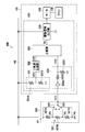
- FIG. 1 is a perspective view of a vehicle seat according to a first embodiment. It is a perspective view of a seat frame built in a vehicle seat. It is the figure which looked at the seat cushion frame and the seat cushion pad from the bottom. It is a disassembled perspective view of the front side of a seat cushion frame. It is the perspective view which looked at the bracket from the bottom. It is the figure (a) which looked at the bracket with which the blower was attached from the front, and the figure (b) seen from the right side. It is the perspective view (a) which looked at the bracket which concerns on the modification 1 from the bottom, and the figure (b) which looked at the bracket with which the blower was attached from the right side. It is the perspective view which looked at the bracket which concerns on the modification 2 from the bottom.
- FIG. 10 is an exploded perspective view of the front side of the seat cushion frame of FIG. 9. It is the perspective view which looked at the bracket of FIG. 9 from the bottom.
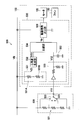
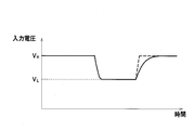
- FIG. 10 is an XX sectional view (a) of FIG. 9 and a YY sectional view (b) of FIG. It is a figure which shows the structure of the motor drive device for vehicles. It is the figure (a) which shows the voltage input into a comparison part, the figure (b) which shows the output of a comparison part, and the figure (c) which shows the output of the comparison part in a comparative example.
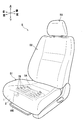
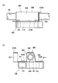
- the vehicle seat S is a seat used for a driver's seat of an automobile, and mainly includes a seat cushion S1, an example of a seat body, a seat back S2, and a headrest S3. .
- a seat cushion S1 an example of a seat body
- a seat back S2 a seat back S3
- a headrest S3. a seat cushion S1
- front and rear, left and right, and top and bottom are used with reference to an occupant sitting on the vehicle seat S.
- a seat frame F is built in the seat cushion S1 and the seat back S2.
- the seat frame F is mainly composed of a seat cushion frame F1 constituting a frame of the seat cushion S1 and a seat back frame F2 constituting a frame of the seat back S2.
- the seat cushion S ⁇ b> 1 is configured by covering a seat cushion frame F ⁇ b> 1 with a seat cushion pad 1 made of a cushion material such as urethane foam and a skin material 2 made of synthetic leather or fabric. .
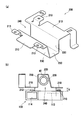
- the seat cushion frame F1 connects the pair of left and right side frames 10, the pan frame 30 that connects the front portions of the side frames 10, and the front and rear ends of the side frames 10.
- a connection pipe 40 (see also FIG. 3) as an example of a cylindrical connection member is mainly provided.
- the left and right side frames 10 are metal frames extending in the front-rear direction, and are spaced apart from each other on the left and right.
- the pan frame 30 is formed by press-molding a metal plate, and has a shape in which a central portion is recessed downward.
- the S spring 20 is a long spring extending in the front-rear direction, and is formed to be bent a plurality of times in the left-right direction.
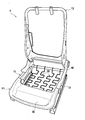
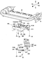
- the seat cushion pad 1 has an air passage 1 ⁇ / b> A formed inside and a plurality of air outlets 1 ⁇ / b> B formed on the upper surface, and air sent from the blower 100 into the air passage 1 ⁇ / b> A is indicated by an arrow. It is comprised so that ventilation can be carried out toward the passenger
- a blower 100 and a bracket 200 are provided under the pan frame 30, that is, on the side opposite to the occupant with the seat cushion pad 1 interposed therebetween.
- the blower 100 is a blower for sending air toward the ventilation path 1A through the duct 1C, and includes a housing 110, a motor 120, and a fan 130.
- the housing 110 includes a cylindrical portion 111 formed in a cylindrical shape, and a blowout portion 112 that protrudes to the left from the front portion of the cylindrical portion 111 and is connected to the duct 1 ⁇ / b> C. Yes.
- the cylindrical portion 111 is formed with a suction port 113, and the blowout portion 112 is formed with a blowout port 114.
- the suction port 113 is an opening for sucking air into the housing 110 by the rotation of the fan 130, and is formed in a circular shape on the upper surface of the cylindrical portion 111 so as to face the upper side (the pan frame 30 side).
- the suction port 113 is formed slightly to the left of the upper surface of the cylindrical portion 111. Specifically, the suction port 113 gradually increases as the distance between the inner periphery of the cylindrical portion 111 and the outer periphery of the fan 130 starts from the center left position of the cylindrical portion 111 and goes downstream in the clockwise direction in the figure. It is arranged in such a position. Thereby, the ventilation path 115 until it goes to the blower outlet 114 (blowing part 112) of the air which came out of the fan 130 is formed so that it may spread gradually.
- the suction port 113 is not exposed with a cover member such as a net or a lattice that covers the suction port 113, and is exposed.
- the suction port 113 consists of a single opening.
- the air outlet 114 is an opening for blowing out air sucked from the air inlet 113, and is formed on the left surface of the air outlet 112. Thereby, the blower outlet 114 is connected with the ventilation path 1A via the duct 1C.
- the housing 110 has three projecting portions 116 projecting from the outer peripheral surface of the cylindrical portion 111.
- a total of three projecting portions 116 are provided at the front right portion of the cylindrical portion 111 and one at each of the left and right end portions of the rear portion, and a hole 116A penetrating vertically is provided.
- the motor 120 is a drive source for rotationally driving a fan 130 such as a DC (Direct Current) brushless motor, and is provided inside the housing 110.
- a fan 130 such as a DC (Direct Current) brushless motor
- the fan 130 is connected to the output shaft of the motor 120 and is provided inside the housing 110, specifically, at a position along the edge of the suction port 113 of the housing 110.
- the blower 100 is configured so that the air sucked from the suction port 113 by the rotation of the fan 130 flows in the ventilation passage 115 in the clockwise direction in the drawing and reaches the blowout port 114. It is configured.
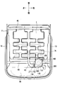
- the bracket 200 is a sheet metal member for fixing the blower 100 to the pan frame 30 and is disposed at a position facing the suction port 113 of the pan frame 30.
- the bracket 200 is opposed to the suction port 113 between the pair of base portions 210 disposed at positions corresponding to the front and rear end sides of the suction port 113 and the pair of base portions 210. It has the opposing part 220 arrange
- FIG. 1 the bracket 200 is opposed to the suction port 113 between the pair of base portions 210 disposed at positions corresponding to the front and rear end sides of the suction port 113 and the pair of base portions 210. It has the opposing part 220 arrange
- the pair of base portions 210 are provided with a total of three welding nuts 211 for attaching the blower 100, one for the front base portion 210A and two for the rear base portion 210B.
- the welding nut 211 is disposed at a position corresponding to the protruding portion 116 of the blower 100 on the upper surface of the base portion 210. Accordingly, the blower 100 is fixed to the lower surface of the base portion 210 of the bracket 200 by fitting the bolt inserted through the hole 116 ⁇ / b> A of the protruding portion 116 to the welding nut 211.
- the front base portion 210A is provided with an extending portion 212 extending upward on the front side at the left end.
- the extending part 212 has a bent part 212A whose upper end is bent to the left.
- the facing portion 220 is a portion that is fixed to the pan frame 30 together with the bent portion 212A by welding or the like, and as shown in FIGS. 6A and 6B, the vertical position is substantially the same as the bent portion 212A. It is arrange
- the pair of connection portions 230 are walls that connect the front and rear ends of the facing portion 220 and the pair of base portions 210.
- the pair of connection portions 230 rises from the base portion 210 and extends to the outside of the range where the suction port 113 is disposed in the left-right direction. As a result, even if a foreign object moves from the front-rear direction toward the suction port 113, the connecting portion 230 blocks the foreign object.
- the bracket 200 has a concave portion 240 that is recessed upward by the facing portion 220 and the connecting portion 230 described above. As a result, a space is created between the suction port 113 and the bracket 200.
- the recessed part 240 is open
- the connecting pipe 40 is disposed in the space above the suction port 113, and the flow path in the recess 240 is appropriately narrowed, so that large foreign matter that moves from the left and right directions of the connecting pipe 40 does not enter. Yes.
- the upper surface of the facing portion 220 of the bracket 200 and the bent portion 212A are fixed to the pan frame 30 by welding or the like.
- the front connection pipe 40 is inserted into the concave portion 240, and the pan frame 30 is disposed on the side frame 10.
- a bolt is inserted into the hole 116 ⁇ / b> A of the projecting portion 116 of the blower 100 and is fitted into the welding nut 211 of the bracket 200 to fix the blower 100 to the bracket 200.
- the suction port 113 of the blower 100 faces upward, it is possible to suppress dust and the like from being sucked from the suction port 113. Further, since the suction port 113 and the bracket 200 face each other, it is possible to prevent foreign matter from entering the suction port 113.
- bracket 200 since a space is formed between the suction port 113 and the bracket 200, air can be easily sucked from the suction port 113. Further, since the bracket 200 has the recess 240, the rigidity of the bracket 200 can be increased.
- the foreign matter from the front-rear direction of the connecting portion 230 is blocked, the foreign matter can be prevented from entering the suction port 113 from the front-rear direction.
- the connecting pipe 40 blocks foreign matter from the left and right direction, it is possible to prevent large foreign matter from entering the suction port 113 from the left and right direction.
- the suction port 113 is exposed. However, the suction port 113 is directed upward to block foreign matter from the front, rear, left and right, so that a separate cover member is not required. , Foreign matter can be prevented from entering the suction port 113.
- the blower 100 is fixed to the lower surface of the base portion 210.
- the present invention is not limited to this, for example, as shown in FIGS. 7 (a) and 7 (b).
- the base part 210 may be separated from the blower 100.
- the bracket 200 in this configuration protrudes from the pair of base portions 210, and is provided with a total of three attachment portions 213 for attaching the blower 100, one on the front side and two on the rear side.
- the front mounting portion 213 extends upward from the base portion 210 and then bends forward, and the rear mounting portion 213 extends upward from the base portion 210 and then bends rearward. Is formed.
- the attachment portion 213 is disposed such that each bent portion is located at a position corresponding to the protruding portion 116 of the blower 100.
- bracket 200 may have a configuration in which a through hole 250 is formed in a portion facing the suction port 113 as shown in FIG.
- the through hole 250 in this configuration is formed in the rear portion of the portion of the bracket 200 that faces the suction port 113.
- the through-hole 250 is formed in a range from the front-rear direction center portion of the opposing portion 220 of the bracket 200 to the front-rear direction center portion of the rear base portion 210B across the rear connection portion 230B.
- the through hole 250 may have any shape.
- a plurality of through holes 250 may be provided.
- the blower 300 and the bracket 400 in this embodiment are disposed under the connecting pipe 40 of the pan frame 30.
- the blower 300 includes a housing 310, a motor 120, and a fan 130, similar to the blower 100 of the first embodiment.
- the housing 310 is made of, for example, a resin such as PBT (polybutylene terephthalate), and includes a cylindrical portion 311 and a blowout portion 312 as in the blower 100 of the first embodiment. As shown in FIGS. 9 and 10, a suction port 313 is formed on the upper surface of the cylindrical portion 311. The blowout part 312 protrudes rearward from the rear part of the cylindrical part 311, and a blower outlet 314 is formed on the rear surface (see FIG. 12A).
- casing 310 is not specifically limited, You may be comprised with materials other than PBT.
- the attachment portion 316 protrudes to the right front of the cylindrical portion 311
- the attachment portion 317 protrudes substantially rearward of the cylindrical portion 311
- the attachment portion 318 protrudes to the left front of the cylindrical portion 311.
- the attachment portion 316 has a circular first engagement hole 316A
- the attachment portion 317 has an oblong second engagement hole 317A that is long in the front and rear
- the attachment portion 318 has a first engagement.
- a circular third engagement hole 318A larger than the hole 316A is formed.
- the first engagement hole 316A, the second engagement hole 317A, and the third engagement hole 318A are portions for fixing the blower 300 to the bracket 400 by inserting a tapping bolt B1 as an example of a fastening member. .
- the first engagement hole 316A is formed so as to be fitted to a first boss 416, which will be described later, so that the position of the blower 300 can be determined at the position of the first engagement hole 316A.
- the second engagement hole 317A engages with a second boss 417, which will be described later, and determines the direction orthogonal to the longitudinal direction of the second engagement hole 317A, that is, the position in the substantially left-right direction, and determines the attitude of the blower 300. It is formed so that it can be. Since the third engagement hole 318A is slightly larger than the first engagement hole 316A, the third engagement hole 318A is formed to engage with a third boss 418 described later with play in the front, rear, left, and right.
- the duct 320 is manufactured, for example, by blow molding olefin-based elastomer (TPO), and connects the blower 300 and the air passage 1A.
- TPO blow molding olefin-based elastomer
- the material of the duct 320 is not specifically limited, You may manufacture with materials other than TPO.
- the duct 320 includes a first extending portion 321 extending in the front-rear direction and a second extending portion 322 extending upward from the rear end of the first extending portion 321 and having an upper end connected to the air passage 1A. .
- the front-end part of the 1st extension part 321 becomes the fitting part 321A formed so that it might fit inside the blower outlet 314.
- FIG. By fitting the fitting portion 321 ⁇ / b> A into the blowout port 314, the blowout port 314 is connected to the ventilation path 1 ⁇ / b> A through the duct 320.
- the bracket 400 is manufactured by injection molding a resin such as PP (polypropylene), for example, and includes a base 410, a first wall 420, and a second wall 430. Yes.
- PP polypropylene
- the material of the bracket 400 is not specifically limited, You may manufacture with materials other than PP.
- the base 410 is a part to which the blower 300 is fixed, and is formed in a substantially rectangular shape.
- the base 410 is formed with a circular hole 411 at a position corresponding to the suction port 313 of the blower 300 (see also FIG. 12B).
- a concave portion 412 that is recessed upward from the lower surface is formed at the left and right center of the front end portion of the base portion 410.
- the first wall 420 protrudes from the base 410 to the opposite side of the occupant, that is, downward, and includes a front wall 421 positioned at the front end of the base 410 and a pair of side walls 422 positioned at the left and right side ends of the base 410. have.
- the front wall 421 is formed in the entire range of the front end of the base 410 in the left-right direction, and the pair of side walls 422 extends from the left and right ends of the front wall 421 in the front-rear direction. Is formed.
- the front wall 421 and the pair of side walls 422 are disposed around the hole 411 of the base 410, that is, around the blower 300.
- the second wall 430 protrudes from the front end of the base 410 to the passenger side, that is, upward, and is located in front of the hole 411 (see also FIGS. 12A and 12B).
- the second wall 430 is formed in the entire left and right range of the front end of the base 410.
- the base 410 is provided with a first boss 416, a second boss 417, and a third boss 418 for attaching the blower 300 so as to protrude downward from the lower surface.
- Each of the bosses 416, 417, and 418 has a cylindrical shape, and holes 416A, 417A, and 418A into which the tapping bolt B1 is engaged are formed on the lower end surface.
- the bosses 416, 417, and 418 have the same shape, and are disposed at positions corresponding to the first engagement hole 316A, the second engagement hole 317A, and the third engagement hole 318A, respectively.
- the base 410 is provided with ribs (reference numerals omitted) that connect the outer peripheral surfaces of the bosses 416, 417, and 418 and the front wall 421 or the side wall 422.
- the ribs have the same amount of protrusion from the base 410, and the vertical positions of the blower 300 can be determined by contacting the mounting portions 316, 317, and 318 of the blower 300.
- the base portion 410 has a pair of fixing portions 413 that extend to the left and right outside of the side wall 422 at the rear end portion.
- the left fixing portion 413 is provided with an extending portion 414 extending downward from the left end.
- a first fixing hole 412A is formed in the bottom wall of the recess 412 described above, a second fixing hole 413A is formed in the left fixing portion 413, and a third fixing hole is formed in the right fixing portion 413. 413B is formed.
- Each of the fixing holes 412A, 413A, 413B is a part for inserting the tapping bolt B2 and fixing the bracket 400 to the pan frame 30.
- the first fixing hole 412A is a circular hole that fits with a boss (not shown) of the pan frame 30 and determines the position of the bracket 400 at the position of the first fixing hole 412A.
- the second fixing hole 413A is an oblong hole that is long on the left and right sides, and is engaged with a boss (not shown) of the pan frame 30 to determine the position in the front-rear direction perpendicular to the longitudinal direction of the oval, and the seat of the bracket 400 The posture with respect to the cushion frame F1 can be determined.
- the third fixing hole 413B is an oval hole larger than the first fixing hole 412A and the second fixing hole 413A, and engages with a boss (not shown) of the pan frame 30 with play in the front, rear, left, and right. It has become.
- first wall 420 and the extending portion 414 are formed with holes 440 penetrating left and right.
- the hole 440 is a hole capable of fixing a clip that supports the harness member of the blower 300 and the harness member of other electrical components.
- each fixing hole 412A, 413A, 413B of the bracket 400 is engaged with a boss corresponding to each hole of the pan frame 30, and each tapping bolt B2 is inserted into each hole of the pan frame 30. Insert into the corresponding boss hole. Thereby, the bracket 400 is fixed to the pan frame 30.
- the fitting portion 321A of the duct 320 is fitted to the blower outlet 314 of the blower 300, and the upper end of the second extending portion 322 is inserted into the opening connected to the air passage 1A.
- the engagement holes 316A, 317A, 318A of the blower 300 are engaged with the bosses 416, 417, 418 of the bracket 400, and the tapping bolts B1 are connected to the bracket 400. Insert into the holes of the bosses 416, 417, 418. Thereby, the blower 300 is attached to the bracket 400.
- the following effects can be obtained in the present embodiment. Since the first wall 420 is disposed around the blower 300, the blower 300 can be protected by the first wall 420. Further, since the bracket 400 is made of resin, the weight of the bracket 400 can be reduced and the degree of freedom in design can be improved.
- the hole 411 is formed at a position corresponding to the suction port 313 of the base 410, air can be sucked into the suction port 313 from the upper side of the base 410.
- the second wall 430 is located around the hole 411, that is, around the suction port 313, the air around the bracket 400 once flows upward to the seat cushion pad 1 as shown in FIG. After approaching, it flows downward toward the suction port 313. That is, the air around the bracket 400 passes over the second wall 430 and enters the suction port 313.
- the presence of the second wall 430 in this way narrows the entry path of foreign matter between the bracket 400 and the seat cushion pad 1, and therefore foreign matter enters the suction port 313 as compared to the configuration without the second wall. Can be suppressed.
- the harness member can be easily fixed to the bracket 400. Further, since the bracket 400 for fixing the harness member is made of resin, even when the harness member is rubbed against the bracket, the harness member can be prevented from being broken or short-circuited.
- the position of the blower 300 with respect to the bracket 400 can be determined by fitting the first boss 416 and the first engagement hole 316A, and the blower with respect to the bracket 400 can be determined by the engagement of the second boss 417 and the second engagement hole 317A. 300 postures can be determined. Further, the second engagement hole 317A is oval, and the third engagement hole 318A engages with the third boss 418 with play so that the second engagement hole 317A is manufactured at the position of each boss 416, 417, 418 of the bracket 400. Even if there is an error, the blower 300 can be easily assembled at the normal position.
- vehicle motor drive device 500 for driving the motor 120 of the blowers 100 and 300 (only the first embodiment is shown) of the first and second embodiments described above will be described.
- the vehicle motor drive device 500 is supplied with electric power from a battery power supply VB as an example of a power supply mounted on the vehicle, and includes a motor 120, an input voltage generation unit 520, and a drive unit 530. I have.
- the motor 120 and the drive unit 530 are provided in the blower 100.
- the motor 120 is a drive source for rotationally driving the fan 130 such as a DC (Direct Current) brushless motor.
- DC Direct Current
- the input voltage generation unit 520 is a part that generates the input voltage V11 to be input to the drive unit 530, and includes a resistor string 521 and a switch unit 522.
- the resistor string 521 is configured by connecting three resistors 521A, 521B, and 521C in series from the battery power source VB side between the battery power source VB and the ground.
- the resistors 521A, 521B, and 521C may have the same resistance value or different resistance values.
- the switch unit 522 is a part for the occupant to switch the air volume when the blower 100 is ON / OFF and when the blower 100 is ON to each level of Hi, Mid, and Low.
- the switch unit 522 includes a connection part P1 on the battery power supply VB side of the resistor string 521, a connection part P2 between the resistors 521A and 521B, a connection part P3 between the resistors 521B and 521C, and the ground of the resistor string 521. Any one of the connection portions P4 on the side is configured to be selectively connected to the output unit 523 of the input voltage generation unit 520. Thus, the voltage at each connection portion selected in the switch unit 522 is output from the output unit 523 to the drive unit 530 as the input voltage V11 in the drive unit 530.
- the air volume of the blower 100 when the switch unit 522 is connected to the connection portion P1, the air volume of the blower 100 becomes Hi output, and when connected to the connection portion P2, the air volume of the blower 100 becomes Mid output, and the connection portion P3. When connected to, the air volume of the blower 100 becomes Low output. Moreover, when the switch part 522 is connected to the connection part P4, the blower 100 is turned off.
- the drive unit 530 is a part that directly receives the input voltage V11 from the input voltage generation unit 520 and drives the motor 120 at a rotation speed corresponding to the magnitude of the input voltage V11.
- the drive unit 530 includes a reference voltage generation unit 531, a triangular wave generation unit 532, a buffer unit 533, a comparison unit 534, and a drive signal output unit 535.
- the reference voltage generation unit 531 is a part that generates the reference voltage V21, and includes two resistors 531A and 531B connected in series between the battery power supply VB and the ground.
- the reference voltage generation unit 531 is configured to output a voltage between the resistor 531A and the resistor 531B to the triangular wave generation unit 532 as the reference voltage V21.
- the resistors 531A and 531B may have the same resistance value or different resistance values.
- the input voltage generation unit 520 and the reference voltage generation unit 531 described above generate the input voltage V11 and the reference voltage V21 by dividing the voltage between the battery power supply VB and the ground by a plurality of resistors connected in series. ing. Therefore, when the voltage of the battery power source VB varies, the input voltage V11 and the reference voltage V21 vary in conjunction with the voltage variation of the battery power source VB.
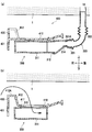
- the triangular wave generation unit 532 is a part that generates a triangular wave V22 having an amplitude corresponding to the reference voltage V21, and is configured to output the triangular wave V22 to the comparison unit 534 (see FIG. 14A).
- the buffer unit 533 adjusts the input voltage V11 to the buffer voltage V12 and outputs it to the comparison unit 534.
- the buffer unit 533 is connected in series between the amplifier 533A to which the input voltage V11 is input and the output of the amplifier 533A and the ground. It consists of two resistors 533B and 533C.
- the buffer unit 533 is configured to output the voltage between the resistor 533B and the resistor 533C to the comparison unit 534 as the buffer voltage V12.
- the comparison unit 534 compares the magnitude relationship between the input voltage V11 and the reference voltage V21, specifically, the buffer voltage V12 and the triangular wave V22, and outputs a pulse signal Vp having a pulse width corresponding to the magnitude of the input voltage V11 to the drive signal output unit. It is configured to output to 535.
- the comparison unit 534 in the present embodiment is set to output a high voltage when it is determined that the buffer voltage V12 is large, and to output a low voltage when it is determined that the triangular wave V22 is large (FIG. 14). (See (a) and (b)) may be set so that the outputs are opposite to each other.
- the drive signal output unit 535 is configured to output to the motor 120 a drive signal for driving the motor 120 at a rotational speed corresponding to the duty ratio of the pulse signal Vp.
- any connection portion of the resistor string 521 in the input voltage generation unit 520 is selected by the switch unit 522.
- the switch unit 522 an input voltage V11 corresponding to the voltage of the connection portion P1 is input to the buffer portion 533, and the buffer voltage V12 (indicated by a broken line) is displayed as shown in FIG.
- the data is input to the comparison unit 534.
- the comparison unit 534 compares the magnitude relationship between the triangular wave V22 (broken line display) generated by the triangular wave generation unit 532 from the reference voltage V21 and the buffer voltage V12, and generates a pulse signal Vp as shown in FIG.
- the data is output to the output unit 535.
- the motor 120 is rotated by the drive signal corresponding to the pulse signal Vp of the drive signal output unit 535, the fan 130 is rotationally driven along with it, and air is sent from the blower 100 to the ventilation path 1A.
- the comparison unit 534 outputs a pulse signal Vp having a pulse width corresponding to each input voltage V11, so that it corresponds to the duty ratio of the pulse signal Vp.
- the motor 120 is driven at the rotational speed. That is, by switching the connection portions P1, P2, and P3 by the switch unit 522, the rotation speed of the motor 120 can be changed by so-called PWM (Pulse Width Modulation) control for controlling the pulse width of the pulse signal Vp.
- PWM Pulse Width Modulation
- the rotation speed of the motor 120 can be determined by switching the input voltage V11 in a plurality of stages by the switch unit 522, the air volume of the blower 100 can be adjusted with a simple configuration using only an analog circuit. it can. Therefore, there is no need to provide an ECU for digital control, and the number of parts in the vehicle seat S and the vehicle motor drive device 500 can be reduced.
- the voltage of the battery power source VB decreases depending on the usage conditions and the like. Therefore, for example, as shown in FIG. 15, in the case of the configuration having the reference voltage generation unit 540 instead of the reference voltage generation unit 531 in FIG. 13, even if the voltage of the battery power supply VB varies, the reference voltage generation unit 540. Is constant, the triangular wave V22 of the triangular wave generator 532 is constant (see the broken line in FIG. 14A), unchanged from the voltage fluctuation of the battery power supply VB.
- the reference voltage generation unit 540 includes a resistor 541 having one end connected to the battery power supply VB, and a Zener diode 542 having a cathode connected to the other end of the resistor 541 and an anode connected to the ground. Yes.
- the voltage at the connection point between the resistor 541 and the Zener diode 542 is input to the triangular wave generation unit 532 as the reference voltage V23.
- Such a reference voltage generation unit 540 applies a voltage equal to or higher than the Zener voltage to the cathode side of the Zener diode 542 even when the battery power supply VB fluctuates, so that current flows from the cathode to the anode.
- a constant reference voltage V23 is output by a so-called Zener effect that flows.
- the comparison part 534 outputs the pulse signal Vp of a pulse width smaller than the pulse width of FIG.14 (b), and the rotational speed of the motor 120 falls, Even if the air volume of the blower 100 is set to Hi, the air volume becomes smaller than that.
- the input voltage V11 and the reference voltage V21 vary according to the voltage variation of the battery power source VB, so the buffer voltage V12 and the triangular wave V22 are changed as shown in FIG. From the broken line state to the solid line state.
- the output of the comparison unit 534 at this time is substantially the same as that before the battery power supply VB changes, as shown in FIG. Therefore, since the influence of the voltage fluctuation of the battery power supply VB can be suppressed, the influence of the voltage fluctuation of the battery power supply VB on the rotation speed of the motor 120 can be reduced.
- vehicle motor drive device 500 has been described above. However, the specific configuration of the vehicle motor drive device 500 can be changed as appropriate.
- the buffer voltage V12 from the buffer unit 533 is directly input to the comparison unit 534.
- a capacitor 550 is provided between the buffer unit 533 and the comparison unit 534. It may be a configuration.
- the capacitor 550 has one end connected between the buffer unit 533 and the comparison unit 534, and the other end connected to the ground. Note that one end of the capacitor 550 only needs to be connected between the input voltage generation unit 520 and the comparison unit 534. For example, one end may be connected between the input voltage generation unit 520 and the buffer unit 533.
- the air volume of the blower 100 is switched from Hi to Low in the switch unit 522 of the input voltage generation unit 520 and the rotational speed of the motor 120 is low, the air volume of the blower 100 is switched to Hi again.
- the input voltage (buffer voltage V12) to the comparison unit 534 is input from V L (input voltage when the air flow rate of the blower 100 is low) to V H (the air flow rate of the blower 100 is high) as indicated by the broken line. Therefore, the rotational speed of the motor 120 suddenly increases.
- the capacitor 550 can vary the input voltage to the comparison unit 534 so as to gradually increase, so that the rotation speed of the motor 120 can be prevented from suddenly increasing. can do.
- the input voltage generation unit 520 includes the resistor string 521 including three resistors.
- the present invention is not limited to this, and may be a resistor string including two resistors, or four or more resistors.
- a resistor string composed of resistors may be used.
- the vehicle motor driving device 500 is applied to the motor 120 for driving the fan 130.
- the present invention is not limited to this, and the motor driving device for devices other than the fan is used. May be applied.
- the seat cushion S1 is exemplified as an example of the seat body, but the present invention is not limited to this, and may be, for example, the seat back S2.
- a blower is provided after the seat back S2.
- the suction port of the blower faces the seat back S2 side (front side).
- the bracket faces the suction port.
- the present invention is not limited to this, and may not face the suction port.
- the blower is fixed to the bracket.
- the present invention is not limited to this, and may be directly fixed to the pan frame 30 or may be fixed to a member other than the bracket. .
- the bracket 200 has the concave portion 240.
- the present invention is not limited to this, and the concave portion 240 may not be provided.
- the recess 240 is configured to be opened to the left and right, but the present invention is not limited to this, and may be configured not to be opened to the left and right.
- the connecting portion 230 extends to the left and right outer sides of the suction port 113, but the present invention is not limited to this, and may not extend to the left and right outer sides.
- connection pipe 40 on the front side has entered the recess 240, but the present invention is not limited to this, and may have a configuration in which the recess 240 does not enter.
- the bracket is attached to the pan frame 30, but the present invention is not limited to this.
- the bracket may be attached to a portion other than the pan frame 30 such as the S spring 20.
- the vehicle seat S used in an automobile is exemplified as the vehicle seat.
- the present invention is not limited to this, and the vehicle seat S is used in other vehicle seats, for example, railway vehicles, ships, and aircrafts. It can also be applied to a sheet to be processed.
Landscapes
- Engineering & Computer Science (AREA)
- Aviation & Aerospace Engineering (AREA)
- Transportation (AREA)
- Mechanical Engineering (AREA)
- Chair Legs, Seat Parts, And Backrests (AREA)
- Seats For Vehicles (AREA)
Abstract
Description
ブラケット200の対向部220の上面及び屈曲部212Aを溶接等によりパンフレーム30に固定する。ブラケット200をパンフレーム30に固定したら、凹部240の部分に前側の連結パイプ40を入り込ませ、パンフレーム30をサイドフレーム10に配置する。そして、ブロワ100の突出部116の穴116Aにボルトを挿通し、ブラケット200の溶接ナット211にはめ込んでブロワ100をブラケット200に固定する。
ブロワ100内に設けられたファン130が回転すると、吸い込み口113から空気がブロワ100内に吸い込まれ、通風路115を通って、吹出口114に達する。その後、空気は、通気路1Aに送り込まれ、送風口1Bから送風される。ここで、従来の構成のように、ブロワの吸い込み口が下側を向いていると、車両のフロアに落ちている埃等を吸い込みやすくなる。
図10に示すように、まず、ブラケット400の各固定孔412A,413A,413Bを、パンフレーム30の各孔に対応したボスに係合させ、各タッピングボルトB2をパンフレーム30の、各孔に対応するボスの穴に挿入する。これにより、ブラケット400がパンフレーム30に固定される。
第1壁420がブロワ300の周囲に配置されているので、第1壁420によりブロワ300を保護することができる。また、ブラケット400が樹脂で作られているので、ブラケット400の軽量化を図ることができるとともに、設計自由度を向上させることができる。
バッテリー電源VBが変動しない状態において、入力電圧生成部520における抵抗列521のいずれかの接続部分をスイッチ部522により選択する。例えば、スイッチ部522により接続部分P1を選択すると、接続部分P1の電圧に相当する入力電圧V11がバッファ部533に入力され、図14(a)に示すように、バッファ電圧V12(破線表示)が比較部534に入力される。比較部534は、参照電圧V21から三角波生成部532により生成された三角波V22(破線表示)とバッファ電圧V12の大小関係を比較して、図14(b)に示すようなパルス信号Vpを駆動信号出力部535に出力する。
1A 通気路
10 サイドフレーム
30 パンフレーム
40 連結パイプ
100 ブロワ
113 吸い込み口
114 吹出口
130 ファン
200 ブラケット
210 ベース部
220 対向部
230 接続部
240 凹部
S1 シートクッション
S 車両用シート
Claims (13)
- 吹出口につながった通気路を有するシート本体と、吸い込み口から吸い込んだ空気を前記通気路に送り込むブロワとを備えた乗物用シートであって、
前記ブロワは、前記シート本体を挟んで乗員とは反対側に配置され、
前記吸い込み口は、前記シート本体側を向いていることを特徴とする乗物用シート。 - 前記シート本体の前記吸い込み口と対向する位置に配置され、前記ブロワを前記シート本体に固定するためのブラケットを備えることを特徴とする請求項1に記載の乗物用シート。
- 前記ブラケットは、前記吸い込み口と対向する凹部を有することを特徴とする請求項2に記載の乗物用シート。
- 前記凹部は、左右に開放していることを特徴とする請求項3に記載の乗物用シート。
- 前記ブラケットは、
一対のベース部と、
前記一対のベース部の間で前記吸い込み口と対向し、前記一対のベース部より前記ブロワから離れて配置された対向部と、
前記対向部の前後端と前記一対のベース部をつなぐ一対の接続部と、を有し、
前記接続部は、壁からなり、左右方向において前記吸い込み口が配置された範囲の外側まで延びていることを特徴とする請求項2から請求項4のいずれか1項に記載の乗物用シート。 - 前記ブラケットは、
一対のベース部と、
前記一対のベース部の間で前記吸い込み口と対向し、前記一対のベース部より前記ブロワから離れて配置された対向部と、
前記対向部と前記一対のベース部をつなぐ一対の接続部と、
前記ベース部から前記ブロワ側に突出して設けられた、前記ブロワを取り付けるための取付部と、を有し、
前記ベース部は、前記ブロワから離間していることを特徴とする請求項2から請求項5のいずれか1項に記載の乗物用シート。 - 前記シート本体は、左右に離間して配置された一対のサイドフレームと、前記一対のサイドフレームを連結する連結部材とを有し、
前記連結部材の少なくとも一部は、前記凹部に入り込んでいることを特徴とする請求項4に記載の乗物用シート。 - 前記シート本体は、左右に離間して配置された一対のサイドフレームと、前記一対のサイドフレームを前側で連結するパンフレームとを有し、
前記ブラケットは、前記パンフレームに取り付けられていることを特徴とする請求項2から請求項7のいずれか1項に記載の乗物用シート。 - 前記ブラケットは、前記吸い込み口に対向する部分に貫通孔が形成されていることを特徴とする請求項2から請求項8のいずれか1項に記載の乗物用シート。
- 前記ブロワを前記シート本体に固定するためのブラケットを備え、
前記ブラケットは、樹脂で作られており、前記ブロワが固定される基部と、前記基部から乗員とは反対側に突出し、前記ブロワの周囲の少なくとも一部に配置された第1壁とを有することを特徴とする請求項1に記載の乗物用シート。 - 前記ブラケットは、前記基部から乗員側に突出する第2壁を有し、
前記基部には、前記吸い込み口に対応した孔が形成されていることを特徴とする請求項10に記載の乗物用シート。 - 前記ブラケットには、ハーネス部材が固定される穴が設けられていることを特徴とする請求項10または請求項11に記載の乗物用シート。
- 前記ブラケットは、前記ブロワと係合するとともに前記ブロワを固定するための締結部材が締結される第1ボス、第2ボスおよび第3ボスを有し、
前記ブロワは、
前記第1ボスと嵌合して前記ブロワの位置を決める円形の第1係合孔と、
前記第2ボスと係合して長手方向に直交する方向の位置を決める長円形の第2係合孔と、
前記第3ボスと遊びをもって係合する第3係合孔と、を有することを特徴とする請求項10から請求項12のいずれか1項に記載の乗物用シート。
Priority Applications (6)
| Application Number | Priority Date | Filing Date | Title |
|---|---|---|---|
| US15/303,379 US10399470B2 (en) | 2014-04-11 | 2015-04-03 | Vehicle seat |
| CN201580019122.8A CN106163866B (zh) | 2014-04-11 | 2015-04-03 | 交通工具用座椅 |
| JP2016512696A JP6555253B2 (ja) | 2014-04-11 | 2015-04-03 | 乗物用シート |
| US16/547,970 US11001176B2 (en) | 2014-04-11 | 2019-08-22 | Vehicle seat |
| US17/230,585 US11618356B2 (en) | 2014-04-11 | 2021-04-14 | Vehicle seat |
| US18/189,502 US11945347B2 (en) | 2014-04-11 | 2023-03-24 | Vehicle seat |
Applications Claiming Priority (2)
| Application Number | Priority Date | Filing Date | Title |
|---|---|---|---|
| JP2014081976 | 2014-04-11 | ||
| JP2014-081976 | 2014-04-11 |
Related Child Applications (2)
| Application Number | Title | Priority Date | Filing Date |
|---|---|---|---|
| US15/303,379 A-371-Of-International US10399470B2 (en) | 2014-04-11 | 2015-04-03 | Vehicle seat |
| US16/547,970 Continuation US11001176B2 (en) | 2014-04-11 | 2019-08-22 | Vehicle seat |
Publications (1)
| Publication Number | Publication Date |
|---|---|
| WO2015156218A1 true WO2015156218A1 (ja) | 2015-10-15 |
Family
ID=54287794
Family Applications (1)
| Application Number | Title | Priority Date | Filing Date |
|---|---|---|---|
| PCT/JP2015/060564 WO2015156218A1 (ja) | 2014-04-11 | 2015-04-03 | 乗物用シート |
Country Status (4)
| Country | Link |
|---|---|
| US (4) | US10399470B2 (ja) |
| JP (5) | JP6555253B2 (ja) |
| CN (1) | CN106163866B (ja) |
| WO (1) | WO2015156218A1 (ja) |
Cited By (14)
| Publication number | Priority date | Publication date | Assignee | Title |
|---|---|---|---|---|
| JP2018020713A (ja) * | 2016-08-05 | 2018-02-08 | テイ・エス テック株式会社 | 乗物用シート |
| WO2018025797A1 (ja) * | 2016-08-05 | 2018-02-08 | テイ・エス テック株式会社 | 乗物用シート |
| JP2018020714A (ja) * | 2016-08-05 | 2018-02-08 | テイ・エス テック株式会社 | 乗物用シート |
| WO2018056144A1 (ja) * | 2016-09-23 | 2018-03-29 | アイシン精機 株式会社 | 吸排気バルブ装置及び車両用シート装置 |
| JP6309130B1 (ja) * | 2017-03-24 | 2018-04-11 | テイ・エス テック株式会社 | 乗物用シート |
| JP2018062303A (ja) * | 2016-10-14 | 2018-04-19 | トヨタ紡織株式会社 | 空調装置 |
| JP2018162058A (ja) * | 2018-03-13 | 2018-10-18 | テイ・エス テック株式会社 | 乗物用シート |
| WO2018216610A1 (ja) * | 2017-05-23 | 2018-11-29 | テイ・エス テック株式会社 | 乗物用シート |
| CN109080515A (zh) * | 2017-06-14 | 2018-12-25 | 捷温公司 | 具有包括分配构件的鼓风机连接组件的空调系统和附接方法 |
| US10538212B2 (en) | 2017-03-24 | 2020-01-21 | Ts Tech Co., Ltd. | Vehicle seat |
| US10654385B2 (en) | 2017-03-24 | 2020-05-19 | Ts Tech Co., Ltd. | Vehicle seat |
| JP2020196384A (ja) * | 2019-06-04 | 2020-12-10 | 日本発條株式会社 | 車両用シートの電装部品配置構造 |
| JP2021112586A (ja) * | 2019-06-13 | 2021-08-05 | テイ・エス テック株式会社 | シート |
| US11850982B2 (en) | 2016-09-30 | 2023-12-26 | Ts Tech Co., Ltd. | Seat with blower |
Families Citing this family (12)
| Publication number | Priority date | Publication date | Assignee | Title |
|---|---|---|---|---|
| US10399470B2 (en) * | 2014-04-11 | 2019-09-03 | Ts Tech Co., Ltd. | Vehicle seat |
| JP6720822B2 (ja) * | 2016-10-14 | 2020-07-08 | トヨタ紡織株式会社 | 乗物用シート |
| BR112019017315B1 (pt) * | 2017-03-01 | 2023-03-07 | Ts Tech Co., Ltd | Assento de veículo |
| WO2019103043A1 (ja) * | 2017-11-27 | 2019-05-31 | テイ・エス テック株式会社 | 乗物用シート |
| US10632883B2 (en) * | 2018-01-25 | 2020-04-28 | Ford Global Technologies, Llc | Multifunctional seat bracket for vehicular seating assembly |
| GB2580026B (en) * | 2018-12-19 | 2023-02-22 | Safran Seats Gb Ltd | Aircraft seat |
| JP7290425B2 (ja) * | 2019-02-01 | 2023-06-13 | テイ・エス テック株式会社 | 乗物用シート |
| US11084405B2 (en) | 2019-02-01 | 2021-08-10 | Ts Tech Co., Ltd. | Vehicle seat having internal support member |
| US11097637B2 (en) | 2019-02-01 | 2021-08-24 | Ts Tech Co., Ltd. | Vehicle seat having internal support member |
| DE102019212992A1 (de) * | 2019-08-29 | 2021-03-04 | Volkswagen Aktiengesellschaft | Fahrzeugsitz und Hintersitzanlage |
| KR20210033817A (ko) * | 2019-09-19 | 2021-03-29 | 서울반도체 주식회사 | 덕트 모듈 및 덕트 모듈을 포함하는 차량용 시트 |
| DE102020113982A1 (de) * | 2020-05-25 | 2021-11-25 | Faurecia Autositze Gmbh | Kraftfahrzeugsitz |
Citations (2)
| Publication number | Priority date | Publication date | Assignee | Title |
|---|---|---|---|---|
| JP2009012550A (ja) * | 2007-07-03 | 2009-01-22 | Valeo Thermal Systems Japan Corp | 自動車用シート空調装置 |
| JP2013177027A (ja) * | 2012-02-28 | 2013-09-09 | Toyota Boshoku Corp | 車両用シート |
Family Cites Families (38)
| Publication number | Priority date | Publication date | Assignee | Title |
|---|---|---|---|---|
| JPS5482014A (en) | 1977-12-12 | 1979-06-29 | Kiyoshi Hama | Speed control device for dc motor |
| SE504973C2 (sv) * | 1995-09-14 | 1997-06-02 | Walinov Ab | I en ventilerad fordonsstol ingående fläktanordning |
| JPH10103059A (ja) * | 1996-09-24 | 1998-04-21 | Kubota Corp | 農作業車の原動部騒音漏出し防止構造 |
| US5927817A (en) * | 1997-08-27 | 1999-07-27 | Lear Corporation | Ventilated vehicle seat assembly |
| JP2001327363A (ja) * | 2000-05-25 | 2001-11-27 | Tetsuya Sakamoto | 身体支持装置 |
| JP3861674B2 (ja) * | 2001-11-30 | 2006-12-20 | 株式会社デンソー | 車両用シート空調装置および空調装置内蔵型車両用シート |
| EP1398270B1 (en) * | 2002-09-11 | 2005-08-31 | Structural Design & Analysis S.A. en abrégé SD&A S.A. | Shoulder belt-type aircraft seat comprising an energy absorbing device |
| DE10259648B4 (de) | 2002-12-18 | 2006-01-26 | W.E.T. Automotive Systems Ag | Klimatisierter Sitz und Klimatisierungseinrichtung für einen ventilierten Sitz |
| DE10259621B4 (de) * | 2002-12-18 | 2005-12-01 | W.E.T. Automotive Systems Ag | Fahrzeugsitz und zugehörige Klimatisierungseinrichtung |
| US7425034B2 (en) * | 2003-10-17 | 2008-09-16 | W.E.T. Automotive Systems Ag | Automotive vehicle seat having a comfort system |
| JP4394521B2 (ja) | 2004-06-02 | 2010-01-06 | テイ・エス テック株式会社 | 車両用シート |
| JP2006102329A (ja) * | 2004-10-07 | 2006-04-20 | T S Tec Kk | 車両用シート |
| US20060087160A1 (en) * | 2004-10-25 | 2006-04-27 | Hanh Dong | Apparatus for providing fluid through a vehicle seat |
| JP4513555B2 (ja) * | 2004-12-24 | 2010-07-28 | 株式会社デンソー | 車両用シート空調装置 |
| EP1851087A1 (en) * | 2005-02-07 | 2007-11-07 | L&P Property Management Company | Heat, cool, and ventilate system for automotive applications |
| JP3901198B2 (ja) * | 2005-06-27 | 2007-04-04 | 株式会社デンソー | シート空調装置 |
| JP2007126047A (ja) | 2005-11-04 | 2007-05-24 | Denso Corp | 車両用シート空調装置 |
| US7591507B2 (en) * | 2006-04-13 | 2009-09-22 | Amerigon Incorporated | Tie strap for climate controlled seat |
| US7607739B2 (en) * | 2006-05-08 | 2009-10-27 | Lear Corporation | Air routing system and method for use with a vehicle seat |
| US7419209B1 (en) * | 2007-05-30 | 2008-09-02 | Lear Corporation | Seat assembly providing airflow path to cool batteries |
| JP5091579B2 (ja) | 2007-07-26 | 2012-12-05 | 矢崎総業株式会社 | 負荷制御装置 |
| JP5188884B2 (ja) * | 2008-06-03 | 2013-04-24 | トヨタ紡織株式会社 | 車両用シート |
| US9121414B2 (en) * | 2010-11-05 | 2015-09-01 | Gentherm Incorporated | Low-profile blowers and methods |
| JP2012165830A (ja) | 2011-02-10 | 2012-09-06 | Maspro Denkoh Corp | 空調シート |
| JP5784946B2 (ja) | 2011-03-30 | 2015-09-24 | ダイハツ工業株式会社 | 車両用シート |
| US8727434B2 (en) * | 2011-04-07 | 2014-05-20 | Toyota Boshoku Kabushiki Kaisha | Vehicle seat |
| JP5855403B2 (ja) | 2011-09-22 | 2016-02-09 | 株式会社タチエス | 空調シート |
| DE202011107805U1 (de) * | 2011-10-06 | 2013-02-19 | I.G. Bauerhin Gmbh | Sitzgestell für einen Fahrzeugsitz |
| US20130328359A1 (en) * | 2012-06-10 | 2013-12-12 | Bbreezer Llc | Ventilation and Cooling System for an Office Chair |
| WO2014058429A1 (en) * | 2012-10-11 | 2014-04-17 | Kongsberg Automotive, Inc. | Ventilated and heated vehicle seat assembly |
| JP6094371B2 (ja) * | 2013-05-15 | 2017-03-15 | 株式会社日本自動車部品総合研究所 | シート空調用の送風機を備えたシート |
| JP6024619B2 (ja) * | 2013-08-20 | 2016-11-16 | 株式会社日本自動車部品総合研究所 | シート空調用送風機 |
| TWM469220U (zh) * | 2013-08-30 | 2014-01-01 | jing-lun Yang | 兒童用透氣椅墊裝置及兒童用透氣椅裝置 |
| US10399470B2 (en) | 2014-04-11 | 2019-09-03 | Ts Tech Co., Ltd. | Vehicle seat |
| CN107406020B (zh) * | 2015-07-01 | 2019-09-10 | 提爱思科技股份有限公司 | 交通工具用座椅 |
| JP6524843B2 (ja) * | 2015-07-31 | 2019-06-05 | トヨタ紡織株式会社 | 乗物用シート |
| US10137807B2 (en) * | 2016-04-01 | 2018-11-27 | Fca Us Llc | Ventilated vehicle seat with blind coupling and related method |
| JP6720822B2 (ja) * | 2016-10-14 | 2020-07-08 | トヨタ紡織株式会社 | 乗物用シート |
-
2015
- 2015-04-03 US US15/303,379 patent/US10399470B2/en active Active
- 2015-04-03 WO PCT/JP2015/060564 patent/WO2015156218A1/ja active Application Filing
- 2015-04-03 JP JP2016512696A patent/JP6555253B2/ja active Active
- 2015-04-03 CN CN201580019122.8A patent/CN106163866B/zh active Active
-
2019
- 2019-07-05 JP JP2019126498A patent/JP6867600B2/ja active Active
- 2019-08-22 US US16/547,970 patent/US11001176B2/en active Active
-
2021
- 2021-04-07 JP JP2021065470A patent/JP7185153B2/ja active Active
- 2021-04-14 US US17/230,585 patent/US11618356B2/en active Active
-
2022
- 2022-11-22 JP JP2022186615A patent/JP7460928B2/ja active Active
-
2023
- 2023-03-24 US US18/189,502 patent/US11945347B2/en active Active
-
2024
- 2024-03-18 JP JP2024042270A patent/JP2024061878A/ja active Pending
Patent Citations (2)
| Publication number | Priority date | Publication date | Assignee | Title |
|---|---|---|---|---|
| JP2009012550A (ja) * | 2007-07-03 | 2009-01-22 | Valeo Thermal Systems Japan Corp | 自動車用シート空調装置 |
| JP2013177027A (ja) * | 2012-02-28 | 2013-09-09 | Toyota Boshoku Corp | 車両用シート |
Cited By (35)
| Publication number | Priority date | Publication date | Assignee | Title |
|---|---|---|---|---|
| US11027631B2 (en) | 2016-08-05 | 2021-06-08 | Ts Tech Co., Ltd. | Vehicle seat |
| WO2018025797A1 (ja) * | 2016-08-05 | 2018-02-08 | テイ・エス テック株式会社 | 乗物用シート |
| JP2018020714A (ja) * | 2016-08-05 | 2018-02-08 | テイ・エス テック株式会社 | 乗物用シート |
| CN109562705A (zh) * | 2016-08-05 | 2019-04-02 | 提爱思科技股份有限公司 | 车辆座椅 |
| EP3495199A4 (en) * | 2016-08-05 | 2019-08-21 | TS Tech Co., Ltd. | VEHICLE SEAT |
| JP2018020713A (ja) * | 2016-08-05 | 2018-02-08 | テイ・エス テック株式会社 | 乗物用シート |
| US10743668B2 (en) | 2016-09-23 | 2020-08-18 | Aisin Seiki Kabushiki Kaisha | Intake/exhaust valve device and vehicular seat device |
| CN109715440A (zh) * | 2016-09-23 | 2019-05-03 | 爱信精机株式会社 | 进气排气阀装置及车辆用座椅装置 |
| JP2018047874A (ja) * | 2016-09-23 | 2018-03-29 | アイシン精機株式会社 | 吸排気バルブ装置及び車両用シート装置 |
| WO2018056144A1 (ja) * | 2016-09-23 | 2018-03-29 | アイシン精機 株式会社 | 吸排気バルブ装置及び車両用シート装置 |
| US11850982B2 (en) | 2016-09-30 | 2023-12-26 | Ts Tech Co., Ltd. | Seat with blower |
| JP2018062303A (ja) * | 2016-10-14 | 2018-04-19 | トヨタ紡織株式会社 | 空調装置 |
| US10639958B2 (en) | 2016-10-14 | 2020-05-05 | Toyota Boshoku Kabushiki Kaisha | Air conditioning device |
| US10889217B2 (en) | 2017-03-24 | 2021-01-12 | Ts Tech Co., Ltd. | Vehicle seat |
| WO2018173319A1 (ja) * | 2017-03-24 | 2018-09-27 | テイ・エス テック株式会社 | 乗物用シート |
| CN110267848A (zh) * | 2017-03-24 | 2019-09-20 | 提爱思科技股份有限公司 | 交通工具用座椅 |
| US10532679B2 (en) | 2017-03-24 | 2020-01-14 | Ts Tech Co., Ltd. | Vehicle seat |
| US10538212B2 (en) | 2017-03-24 | 2020-01-21 | Ts Tech Co., Ltd. | Vehicle seat |
| JP6309130B1 (ja) * | 2017-03-24 | 2018-04-11 | テイ・エス テック株式会社 | 乗物用シート |
| US11745679B2 (en) | 2017-03-24 | 2023-09-05 | Ts Tech Co., Ltd. | Vehicle seat |
| US10654385B2 (en) | 2017-03-24 | 2020-05-19 | Ts Tech Co., Ltd. | Vehicle seat |
| JP2018161915A (ja) * | 2017-03-24 | 2018-10-18 | テイ・エス テック株式会社 | 乗物用シート |
| US10857958B2 (en) | 2017-03-24 | 2020-12-08 | Ts Tech Co., Ltd. | Vehicle seat |
| US11370338B2 (en) | 2017-03-24 | 2022-06-28 | Ts Tech Co., Ltd. | Vehicle seat |
| US11235719B2 (en) | 2017-03-24 | 2022-02-01 | Ts Tech Co., Ltd. | Vehicle seat |
| JP7152672B2 (ja) | 2017-05-23 | 2022-10-13 | テイ・エス テック株式会社 | 乗物用シート |
| US11654803B2 (en) | 2017-05-23 | 2023-05-23 | Ts Tech Co., Ltd. | Conveyance seat |
| WO2018216610A1 (ja) * | 2017-05-23 | 2018-11-29 | テイ・エス テック株式会社 | 乗物用シート |
| JPWO2018216610A1 (ja) * | 2017-05-23 | 2020-03-26 | テイ・エス テック株式会社 | 乗物用シート |
| CN109080515A (zh) * | 2017-06-14 | 2018-12-25 | 捷温公司 | 具有包括分配构件的鼓风机连接组件的空调系统和附接方法 |
| JP2018162058A (ja) * | 2018-03-13 | 2018-10-18 | テイ・エス テック株式会社 | 乗物用シート |
| JP7453575B2 (ja) | 2018-03-13 | 2024-03-21 | テイ・エス テック株式会社 | 乗物用シート |
| JP2020196384A (ja) * | 2019-06-04 | 2020-12-10 | 日本発條株式会社 | 車両用シートの電装部品配置構造 |
| JP2021112586A (ja) * | 2019-06-13 | 2021-08-05 | テイ・エス テック株式会社 | シート |
| JP7315860B2 (ja) | 2019-06-13 | 2023-07-27 | テイ・エス テック株式会社 | シート |
Also Published As
| Publication number | Publication date |
|---|---|
| JP2024061878A (ja) | 2024-05-08 |
| US10399470B2 (en) | 2019-09-03 |
| JP7185153B2 (ja) | 2022-12-07 |
| JP2023015368A (ja) | 2023-01-31 |
| JP2021151862A (ja) | 2021-09-30 |
| JP7460928B2 (ja) | 2024-04-03 |
| CN106163866B (zh) | 2018-10-16 |
| US20210229581A1 (en) | 2021-07-29 |
| JP6867600B2 (ja) | 2021-04-28 |
| US20230226959A1 (en) | 2023-07-20 |
| US11618356B2 (en) | 2023-04-04 |
| US20190375317A1 (en) | 2019-12-12 |
| US11945347B2 (en) | 2024-04-02 |
| JP2019163062A (ja) | 2019-09-26 |
| JPWO2015156218A1 (ja) | 2017-04-13 |
| JP6555253B2 (ja) | 2019-08-07 |
| US11001176B2 (en) | 2021-05-11 |
| US20170036575A1 (en) | 2017-02-09 |
| CN106163866A (zh) | 2016-11-23 |
Similar Documents
| Publication | Publication Date | Title |
|---|---|---|
| JP6555253B2 (ja) | 乗物用シート | |
| US10507746B2 (en) | Vehicle seat | |
| US8727434B2 (en) | Vehicle seat | |
| WO2018173319A1 (ja) | 乗物用シート | |
| WO2018025797A1 (ja) | 乗物用シート | |
| US8488818B2 (en) | Interior structural assembly for a vehicle | |
| WO2019008871A1 (ja) | 吸気グリル及び車両 | |
| US10661692B2 (en) | Vehicle seat pump assembly | |
| JP2010094146A (ja) | シートおよびシート空調装置 | |
| JP6982258B2 (ja) | 乗物用シート | |
| JP6308862B2 (ja) | 車両用シート空調装置 | |
| JP2018020713A (ja) | 乗物用シート | |
| JP6652713B2 (ja) | 乗物用シート | |
| JP2021030946A (ja) | 乗物用シート |
Legal Events
| Date | Code | Title | Description |
|---|---|---|---|
| 121 | Ep: the epo has been informed by wipo that ep was designated in this application |
Ref document number: 15776652 Country of ref document: EP Kind code of ref document: A1 |
|
| ENP | Entry into the national phase |
Ref document number: 2016512696 Country of ref document: JP Kind code of ref document: A |
|
| NENP | Non-entry into the national phase |
Ref country code: DE |
|
| WWE | Wipo information: entry into national phase |
Ref document number: 15303379 Country of ref document: US |
|
| 122 | Ep: pct application non-entry in european phase |
Ref document number: 15776652 Country of ref document: EP Kind code of ref document: A1 |