WO2015152136A1 - 蒸着マスクの引張方法、フレーム付き蒸着マスクの製造方法、有機半導体素子の製造方法、及び引張装置 - Google Patents
蒸着マスクの引張方法、フレーム付き蒸着マスクの製造方法、有機半導体素子の製造方法、及び引張装置 Download PDFInfo
- Publication number
- WO2015152136A1 WO2015152136A1 PCT/JP2015/059875 JP2015059875W WO2015152136A1 WO 2015152136 A1 WO2015152136 A1 WO 2015152136A1 JP 2015059875 W JP2015059875 W JP 2015059875W WO 2015152136 A1 WO2015152136 A1 WO 2015152136A1
- Authority
- WO
- WIPO (PCT)
- Prior art keywords
- vapor deposition
- deposition mask
- mask
- tension
- frame
- Prior art date
- Legal status (The legal status is an assumption and is not a legal conclusion. Google has not performed a legal analysis and makes no representation as to the accuracy of the status listed.)
- Ceased
Links
Images









Classifications
-
- C—CHEMISTRY; METALLURGY
- C23—COATING METALLIC MATERIAL; COATING MATERIAL WITH METALLIC MATERIAL; CHEMICAL SURFACE TREATMENT; DIFFUSION TREATMENT OF METALLIC MATERIAL; COATING BY VACUUM EVAPORATION, BY SPUTTERING, BY ION IMPLANTATION OR BY CHEMICAL VAPOUR DEPOSITION, IN GENERAL; INHIBITING CORROSION OF METALLIC MATERIAL OR INCRUSTATION IN GENERAL
- C23C—COATING METALLIC MATERIAL; COATING MATERIAL WITH METALLIC MATERIAL; SURFACE TREATMENT OF METALLIC MATERIAL BY DIFFUSION INTO THE SURFACE, BY CHEMICAL CONVERSION OR SUBSTITUTION; COATING BY VACUUM EVAPORATION, BY SPUTTERING, BY ION IMPLANTATION OR BY CHEMICAL VAPOUR DEPOSITION, IN GENERAL
- C23C14/00—Coating by vacuum evaporation, by sputtering or by ion implantation of the coating forming material
- C23C14/04—Coating on selected surface areas, e.g. using masks
- C23C14/042—Coating on selected surface areas, e.g. using masks using masks
-
- B—PERFORMING OPERATIONS; TRANSPORTING
- B05—SPRAYING OR ATOMISING IN GENERAL; APPLYING FLUENT MATERIALS TO SURFACES, IN GENERAL
- B05B—SPRAYING APPARATUS; ATOMISING APPARATUS; NOZZLES
- B05B12/00—Arrangements for controlling delivery; Arrangements for controlling the spray area
- B05B12/16—Arrangements for controlling delivery; Arrangements for controlling the spray area for controlling the spray area
- B05B12/20—Masking elements, i.e. elements defining uncoated areas on an object to be coated
- B05B12/24—Masking elements, i.e. elements defining uncoated areas on an object to be coated made at least partly of flexible material, e.g. sheets of paper or fabric
-
- B—PERFORMING OPERATIONS; TRANSPORTING
- B05—SPRAYING OR ATOMISING IN GENERAL; APPLYING FLUENT MATERIALS TO SURFACES, IN GENERAL
- B05D—PROCESSES FOR APPLYING FLUENT MATERIALS TO SURFACES, IN GENERAL
- B05D1/00—Processes for applying liquids or other fluent materials
- B05D1/32—Processes for applying liquids or other fluent materials using means for protecting parts of a surface not to be coated, e.g. using stencils, resists
-
- H—ELECTRICITY
- H10—SEMICONDUCTOR DEVICES; ELECTRIC SOLID-STATE DEVICES NOT OTHERWISE PROVIDED FOR
- H10K—ORGANIC ELECTRIC SOLID-STATE DEVICES
- H10K59/00—Integrated devices, or assemblies of multiple devices, comprising at least one organic light-emitting element covered by group H10K50/00
- H10K59/30—Devices specially adapted for multicolour light emission
- H10K59/35—Devices specially adapted for multicolour light emission comprising red-green-blue [RGB] subpixels
-
- H—ELECTRICITY
- H10—SEMICONDUCTOR DEVICES; ELECTRIC SOLID-STATE DEVICES NOT OTHERWISE PROVIDED FOR
- H10K—ORGANIC ELECTRIC SOLID-STATE DEVICES
- H10K71/00—Manufacture or treatment specially adapted for the organic devices covered by this subclass
-
- H—ELECTRICITY
- H10—SEMICONDUCTOR DEVICES; ELECTRIC SOLID-STATE DEVICES NOT OTHERWISE PROVIDED FOR
- H10K—ORGANIC ELECTRIC SOLID-STATE DEVICES
- H10K71/00—Manufacture or treatment specially adapted for the organic devices covered by this subclass
- H10K71/10—Deposition of organic active material
- H10K71/16—Deposition of organic active material using physical vapour deposition [PVD], e.g. vacuum deposition or sputtering
- H10K71/166—Deposition of organic active material using physical vapour deposition [PVD], e.g. vacuum deposition or sputtering using selective deposition, e.g. using a mask
-
- H—ELECTRICITY
- H10—SEMICONDUCTOR DEVICES; ELECTRIC SOLID-STATE DEVICES NOT OTHERWISE PROVIDED FOR
- H10P—GENERIC PROCESSES OR APPARATUS FOR THE MANUFACTURE OR TREATMENT OF DEVICES COVERED BY CLASS H10
- H10P14/00—Formation of materials, e.g. in the shape of layers or pillars
- H10P14/20—Formation of materials, e.g. in the shape of layers or pillars of semiconductor materials
- H10P14/22—Formation of materials, e.g. in the shape of layers or pillars of semiconductor materials using physical deposition, e.g. vacuum deposition or sputtering
-
- H—ELECTRICITY
- H10—SEMICONDUCTOR DEVICES; ELECTRIC SOLID-STATE DEVICES NOT OTHERWISE PROVIDED FOR
- H10K—ORGANIC ELECTRIC SOLID-STATE DEVICES
- H10K50/00—Organic light-emitting devices
- H10K50/10—OLEDs or polymer light-emitting diodes [PLED]
- H10K50/11—OLEDs or polymer light-emitting diodes [PLED] characterised by the electroluminescent [EL] layers
Definitions
- the present invention relates to a method for pulling a vapor deposition mask, a method for manufacturing a vapor deposition mask with a frame, a method for manufacturing an organic semiconductor element, and a tension device.
- Patent Document 1 is laminated with a metal mask provided with slits and a resin mask in which openings corresponding to a pattern to be deposited and formed on the surface of the metal mask are arranged in multiple rows vertically and horizontally.
- a vapor deposition mask is proposed. According to the vapor deposition mask proposed in Patent Document 1, both high definition and light weight can be satisfied even when the size is increased, and a high-definition vapor deposition pattern can be formed. ing.
- the present invention relates to a method for pulling a vapor deposition mask that can pull the vapor deposition mask as described in Patent Document 1 by a simple method, a method for manufacturing a vapor deposition mask with a frame using the tension method, and further vapor deposition
- the main object is to provide a method of manufacturing an organic semiconductor element using a mask and a tension device used in these methods.
- the present invention for solving the above problems is a vapor deposition mask in which a metal mask having slits and a resin mask having openings corresponding to patterns to be vapor deposited at positions overlapping the slits are laminated.
- the tension auxiliary member is overlaid on one surface of the vapor deposition mask, and the tension auxiliary member is disposed on the vapor deposition mask in at least a part of a portion where one surface of the vapor deposition mask and the tension auxiliary member overlap.
- the vapor deposition mask tensioning method further includes a second tension step of pulling the vapor deposition mask in a first direction before the first tension step, wherein the first tension step is fixed to the vapor deposition mask.
- the tension assisting member By pulling the tension assisting member, the vapor deposition mask fixed to the tension assisting member may be pulled in a second direction different from the first direction.
- the present invention for solving the above-described problems is a method for manufacturing a vapor deposition mask with a frame, in which a metal mask having a slit and an opening corresponding to a pattern to be deposited are formed at a position overlapping the slit.
- At least a part of the portion is fixed to the tensile auxiliary member by pulling the tensile auxiliary member fixed to the vapor deposition mask and a tensile auxiliary member fixing step of fixing the tensile auxiliary member to the vapor deposition mask.
- the method of manufacturing a vapor deposition mask with a frame may further include a second tension step of pulling the vapor deposition mask in a first direction before the first tension step, and in the first tension step, the vapor deposition mask is formed on the vapor deposition mask.
- the vapor deposition mask fixed to the tension auxiliary member may be pulled in a second direction different from the first direction by pulling the fixed tension auxiliary member.
- the frame-equipped vapor deposition mask is a frame-equipped vapor deposition mask in which a plurality of the vapor deposition masks are fixed to the frame side by side.
- the at least one vapor deposition mask of the plurality of vapor deposition masks is fixed to the frame through the tension auxiliary member fixing step, the first tension step, and the frame fixing step, and in the first tension step,
- the tension assisting member fixed to the one deposition mask By pulling the tension assisting member fixed to the one deposition mask, the one deposition mask secured to the tension assisting member may be pulled in the direction of the deposition mask adjacent to the one deposition mask. Good.
- the method of manufacturing a vapor deposition mask with a frame may further include a second tension step of pulling the one vapor deposition mask in a direction different from a direction of the adjacent vapor deposition mask before performing the first tension step. May be.
- the present invention for solving the above-described problem is a method for manufacturing an organic semiconductor element, including a step of forming a vapor deposition pattern on a vapor deposition object using a vapor deposition mask with a frame in which the vapor deposition mask is fixed to the frame.
- the vapor deposition mask fixed to the frame is formed with a metal mask having a plurality of slits and an opening corresponding to a pattern for vapor deposition at a position overlapping the slit.
- a tension auxiliary member fixing step of fixing the tension auxiliary member to the vapor deposition mask, and the tension fixed to the vapor deposition mask. Pulling the auxiliary member to pull the vapor deposition mask fixed to the tensile auxiliary member, and the vapor deposition mask in the state pulled in the first tensile step on the frame in which the through hole is formed A frame-deposited mask manufactured by a process including a frame fixing process for fixing.
- the present invention for solving the above problems is a vapor deposition in which a metal mask having slits and a resin mask in which openings corresponding to patterns to be deposited are formed at positions overlapping the slits are laminated.
- a tensioning device for pulling a mask comprising: a tension assisting member; and a driving means for pulling the tension assisting member, wherein the tension assisting member is overlapped with one surface of the vapor deposition mask. It is possible to fix at least a part of a portion overlapping one surface of the vapor deposition mask.
- a vapor deposition mask satisfying both high definition and light weight can be pulled by a simple method even when the size is increased.
- frame of this invention the vapor deposition mask with a flame
- the manufacturing method of the organic semiconductor element of this invention the organic semiconductor element excellent in quality can be manufactured with a sufficient yield.
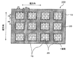
- FIG. 1 It is a figure which shows an example of the vapor deposition mask prepared by a preparatory process
- (a) is a front view seen from the metal mask side
- (b) is AA sectional drawing of (a).
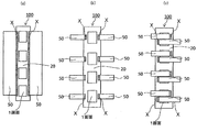
- (a)-(c) is the front view which looked at the vapor deposition mask from the resin mask side. It is a figure for demonstrating a 1st tension
- (a), (b) is the front view which looked at the vapor deposition mask from the resin mask side. It is a front view which shows an example of the vapor deposition mask with a flame
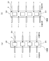
- (A)-(c) is a front view which shows an example of a flame
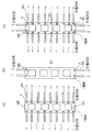
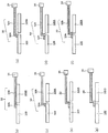
- (A)-(g) is a schematic sectional drawing which shows the state which fixed the tension
- the manufacturing method of the vapor deposition mask with a frame of one embodiment is a vapor deposition obtained by laminating a metal mask in which slits are formed and a resin mask in which openings corresponding to patterns to be vapor deposited are formed at positions overlapping the slits.
- a tension auxiliary member fixing step a first tension step of pulling the vapor deposition mask fixed to the tension auxiliary member by pulling the tension auxiliary member fixed to the vapor deposition mask, and a frame in which the through hole is formed. And a frame fixing step of fixing the vapor deposition mask pulled in the first tensioning step.
- the metal mask 10 having a plurality of slits 15 and openings 25 corresponding to the pattern to be deposited are formed at positions overlapping the slits.
- FIG. 1A is a front view of a vapor deposition mask according to an embodiment as viewed from the metal mask side
- FIG. 1B is a schematic cross-sectional view taken along line AA of FIG.
- the opening shape of the opening 25 is rectangular, but there is no particular limitation on the opening shape, and the opening shape of the opening 25 may be a rhombus or a polygon, a circle, The shape may have a curvature such as an ellipse.
- the rectangular or polygonal opening shape is a preferable opening shape of the opening 25 in that the light emitting area can be increased as compared with the opening shape having a curvature such as a circle or an ellipse.
- the material of the resin mask 20 is not limited.
- a high-definition opening 25 can be formed by laser processing or the like, and a lightweight material with a small dimensional change rate and moisture absorption rate over time and heat is used.
- Such materials include polyimide resin, polyamide resin, polyamideimide resin, polyester resin, polyethylene resin, polyvinyl alcohol resin, polypropylene resin, polycarbonate resin, polystyrene resin, polyacrylonitrile resin, ethylene vinyl acetate copolymer resin, ethylene- Examples thereof include vinyl alcohol copolymer resin, ethylene-methacrylic acid copolymer resin, polyvinyl chloride resin, polyvinylidene chloride resin, cellophane, and ionomer resin.
- a resin material having a thermal expansion coefficient of 16 ppm / ° C. or less is preferable, a resin material having a moisture absorption rate of 1.0% or less is preferable, and a resin material having both conditions is particularly preferable.
- this resin material as a resin mask, the dimensional accuracy of the opening 25 can be improved, and the dimensional change rate and moisture absorption rate over time can be reduced.
- the thickness of the resin mask 20 is not particularly limited, but in the case of further improving the effect of suppressing the generation of shadows, the thickness of the resin mask 20 is preferably 25 ⁇ m or less, and more preferably less than 10 ⁇ m. Although there is no particular limitation on the preferable range of the lower limit value, when the thickness of the resin mask 20 is less than 3 ⁇ m, defects such as pinholes are likely to occur, and the risk of deformation and the like increases. In particular, by setting the thickness of the resin mask 20 to 3 ⁇ m or more and less than 10 ⁇ m, more preferably 4 ⁇ m or more and 8 ⁇ m or less, it is possible to more effectively prevent the influence of shadows when forming a high-definition pattern exceeding 400 ppi. .
- the resin mask 20 and the metal mask 10 to be described later may be bonded directly or via an adhesive layer, but the resin mask 20 and the metal mask via an adhesive layer. 10 is bonded, it is preferable that the total thickness of the resin mask 20 and the pressure-sensitive adhesive layer is within the range of the preferable thickness.
- the shadow is a target vapor deposition because a part of the vapor deposition material released from the vapor deposition source does not reach the vapor deposition target by colliding with the slit of the metal mask or the inner wall surface of the opening of the resin mask. This is a phenomenon in which an undeposited portion having a film thickness smaller than the film thickness occurs.
- the cross-sectional shape of the opening 25 is not particularly limited, and the end faces facing each other of the resin mask forming the opening 25 may be substantially parallel to each other. However, as shown in FIG. It is preferable that the cross-sectional shape has a shape that expands toward the vapor deposition source. In other words, it is preferable to have a tapered surface that expands toward the metal mask 10 side.
- the taper angle can be appropriately set in consideration of the thickness of the resin mask 20 and the like, but a straight line connecting the lower bottom tip of the resin mask opening and the upper bottom tip of the resin mask opening,
- the angle formed with the bottom surface of the resin mask in other words, the surface on the side where the inner wall surface of the opening portion 25 does not contact the metal mask 10 in the cross section in the thickness direction of the inner wall surface constituting the opening portion 25 of the resin mask 20.
- the angle formed with the lower surface of the resin mask is preferably in the range of 5 ° to 85 °, more preferably in the range of 15 ° to 75 °, and 25 ° to 65 °. More preferably, it is within the range of °.
- the end surface forming the opening 25 has a linear shape, but is not limited to this, and has an outwardly convex curved shape, that is, the entire opening 25.
- the shape may be a bowl shape.
- a metal mask 10 is laminated on one surface of the resin mask 20.
- the metal mask 10 is made of metal and has slits 15 extending in the vertical direction or the horizontal direction.
- the slit 15 is synonymous with the opening.
- the slits extending in the vertical direction and the horizontal direction may be arranged in a plurality of rows in the vertical direction and the horizontal direction, and the slits extending in the vertical direction are arranged in a plurality of rows in the horizontal direction.
- the slits extending in the horizontal direction may be arranged in a plurality of rows in the vertical direction. Further, only one row may be arranged in the vertical direction or the horizontal direction.
- vertical direction and lateral direction refer to the vertical and horizontal directions of the drawing, and are any of the longitudinal direction and the width direction of the vapor deposition mask, resin mask, and metal mask. May be.
- the longitudinal direction of the vapor deposition mask, the resin mask, and the metal mask may be “vertical direction”
- the width direction may be “vertical direction”.
- shape of the vapor deposition mask when viewed in plan is a rectangular shape is described as an example, but other shapes, for example, a circular shape, a polygonal shape such as a diamond shape, etc. It is good.
- the longitudinal direction, the radial direction, or an arbitrary direction of the diagonal line is defined as a “longitudinal direction”, and a direction orthogonal to the “longitudinal direction” is referred to as a “width direction (sometimes referred to as a short direction)”. do it.
- the material of the metal mask 10 is not particularly limited, and any conventionally known material can be appropriately selected and used in the field of the evaporation mask, and examples thereof include metal materials such as stainless steel, iron-nickel alloy, and aluminum alloy. . Among them, an invar material that is an iron-nickel alloy can be suitably used because it is less deformed by heat.
- the thickness of the metal mask 10 is not particularly limited, it is preferably 100 ⁇ m or less, more preferably 50 ⁇ m or less, and more preferably 35 ⁇ m or less in order to more effectively prevent the occurrence of shadows. Particularly preferred. When the thickness is less than 5 ⁇ m, the risk of breakage and deformation increases and handling tends to be difficult.
- the opening shape when the slit 15 is viewed in plan view has a rectangular shape, but the opening shape is not particularly limited, and the opening shape of the slit 15 is trapezoidal, Any shape such as a circular shape may be used.
- the cross-sectional shape of the slit 15 formed in the metal mask 10 is not particularly limited, it is preferably a shape having a spread toward the vapor deposition source as shown in FIG. More specifically, the angle formed by the straight line connecting the lower bottom tip of the slit 15 of the metal mask 10 and the upper bottom tip of the slit 15 of the metal mask 10 and the bottom surface of the metal mask 10, in other words, In the thickness direction cross section of the inner wall surface constituting the slit 15 of the metal mask 10, the angle formed by the inner wall surface of the slit 15 and the surface of the metal mask 10 on the side in contact with the resin mask 20 (in the illustrated embodiment, the lower surface of the metal mask).
- the method for laminating the metal mask 10 on the resin mask is not particularly limited, and the resin mask 20 and the metal mask 10 may be bonded together using various adhesives, or a resin mask having self-adhesiveness may be used. . Resin mask 20 and metal mask 10 may have the same size or different sizes. If the resin mask 20 is made smaller than the metal mask 10 and the outer peripheral portion of the metal mask 10 is exposed in consideration of the optional fixing to the frame thereafter, the metal mask 10 It is preferable because it can be easily welded to the frame.
- Embodiment (A) and Embodiment (B) as examples.
- the vapor deposition mask 100 of the embodiment (A) is a vapor deposition mask for simultaneously forming vapor deposition patterns for a plurality of screens, and a plurality of slits 15 are formed on one surface of the resin mask 20.
- the resin mask 20 is provided with openings 25 necessary for forming a plurality of screens, and each slit 15 is provided at a position overlapping at least one entire screen. It is characterized by.
- the vapor deposition mask 100 of the embodiment (A) is a vapor deposition mask used for simultaneously forming vapor deposition patterns for a plurality of screens, and the vapor deposition patterns corresponding to a plurality of products are simultaneously formed with one vapor deposition mask 100. Can do.
- the “opening” referred to in the vapor deposition mask of the embodiment (A) means a pattern to be produced using the vapor deposition mask 100 of the embodiment (A).
- the vapor deposition mask is an organic layer in an organic EL display.
- the shape of the opening 25 is the shape of the organic layer.
- “one screen” includes an assembly of openings 25 corresponding to one product.
- an aggregate of organic layers that is, an aggregate of openings 25 serving as an organic layer is “one screen”.
- the “one screen” is arranged on the resin mask 20 for a plurality of screens at predetermined intervals. Yes. That is, the resin mask 20 is provided with openings 25 necessary for forming a plurality of screens.
- the metal mask 10 provided with a plurality of slits 15 is provided on one surface of the resin mask, and each slit is provided at a position overlapping with at least one entire screen. It is characterized by that.
- the length is the same as the length of the slit 15 in the vertical direction, and is the same as the metal mask 10.
- metal wire portions having a thickness may be collectively referred to simply as metal wire portions.
- the vapor deposition mask 100 of the embodiment (A) when the size of the opening 25 necessary to configure one screen or the pitch between the openings 25 configuring one screen is narrowed, for example, exceeds 400 ppi. Even when the size of the openings 25 and the pitch between the openings 25 are extremely small in order to form a screen, it is possible to prevent interference due to the metal line portion and to form a high-definition image. It becomes possible.
- FIGS. In the form shown in the figure, a region closed by a broken line is one screen.
- a small number of openings 25 are aggregated as one screen.
- the present invention is not limited to this form.
- one opening 25 is defined as one pixel
- one screen There may be an opening 25 of several million pixels.
- one screen is constituted by an aggregate of openings 25 in which a plurality of openings 25 are provided in the vertical and horizontal directions.
- one screen is constituted by an aggregate of openings 25 in which a plurality of openings 25 are provided in the horizontal direction.
- one screen is constituted by an aggregate of openings 25 in which a plurality of openings 25 are provided in the vertical direction.
- a slit 15 is provided at a position overlapping the entire screen.
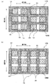
- the slit 15 may be provided at a position that overlaps only one screen, and is provided at a position that overlaps two or more entire screens, as shown in FIGS. It may be. 5A, in the resin mask 10 shown in FIG. 2, a slit 15 is provided at a position overlapping the entire two screens that are continuous in the horizontal direction. In FIG. 5B, the slit 15 is provided at a position overlapping the entire three screens that are continuous in the vertical direction.
- the pitch between the openings 25 constituting one screen and the pitch between the screens will be described.
- the pitch between the openings 25 constituting one screen and the size of the openings 25, can be set as appropriate according to the pattern to be deposited.
- the horizontal pitch (P1) and vertical pitch (P2) of the adjacent openings 25 in the openings 25 constituting one screen are about 60 ⁇ m. It becomes.
- the size of the opening is about 500 ⁇ m 2 to 1000 ⁇ m 2 .
- one opening 25 is not limited to corresponding to one pixel. For example, depending on the pixel arrangement, a plurality of pixels can be integrated into one opening 25.
- the horizontal pitch (P3) and the vertical pitch (P4) between the screens are not particularly limited. However, as shown in FIG. 2, when one slit 15 is provided at a position overlapping the entire screen. In this case, a metal line portion exists between the screens. Therefore, the vertical pitch (P4) and the horizontal pitch (P3) between the screens are the vertical pitch (P2) and the horizontal pitch (P1) of the openings 25 provided in one screen. If it is smaller than or approximately equal, the metal wire portion existing between the screens is easily broken. Therefore, in consideration of this point, it is preferable that the pitch (P3, P4) between the screens is wider than the pitch (P1, P2) between the openings 25 constituting one screen. An example of the pitch (P3, P4) between the screens is about 1 mm to 100 mm. Note that the pitch between the screens means a pitch between adjacent openings in one screen and another screen adjacent to the one screen. The same applies to the pitch of the openings 25 and the pitch between the screens in the vapor deposition mask of the embodiment (B) described later.
- the pitch between two or more screens provided at a position overlapping with one slit 15 may be substantially equal to the pitch between the openings 25 constituting one screen.
- grooves (not shown) extending in the vertical direction or the horizontal direction of the resin mask 20 may be formed in the resin mask 20.
- the resin mask 20 may thermally expand, which may cause changes in the size and position of the opening 25.
- the groove may be provided between the openings 25 constituting one screen or at a position overlapping with the openings 25, but is preferably provided between the screens.
- the groove may be provided only on one surface of the resin mask, for example, the surface in contact with the metal mask, or may be provided only on the surface not in contact with the metal mask. Alternatively, it may be provided on both surfaces of the resin mask 20.
- a groove extending in the vertical direction between adjacent screens may be formed, or a groove extending in the horizontal direction may be formed between adjacent screens. Furthermore, it is possible to form the grooves in a combination of these.
- the depth and width of the groove are not particularly limited. However, when the depth of the groove is too deep or too wide, the rigidity of the resin mask 20 tends to decrease, so this point is taken into consideration. It is necessary to set it. Further, the cross-sectional shape of the groove is not particularly limited, and may be arbitrarily selected in consideration of a processing method such as a U shape or a V shape. The same applies to the vapor deposition mask of the embodiment (B).
- the vapor deposition mask of embodiment (B) has one slit (one hole 16 on one surface of the resin mask 20 provided with a plurality of openings 25 corresponding to the pattern to be produced by vapor deposition. ) Is laminated, and all of the plurality of openings 25 are provided in positions overlapping one hole provided in the metal mask 10.
- the opening 25 referred to in the vapor deposition mask of the embodiment (B) means an opening necessary for forming the vapor deposition pattern on the vapor deposition target, and is not necessary for forming the vapor deposition pattern on the vapor deposition target.
- the portion may be provided at a position that does not overlap with one hole 16.
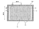
- FIG. 6 is a front view of the vapor deposition mask showing an example of the vapor deposition mask of the embodiment (B) as viewed from the metal mask side.
- the metal mask 10 having one hole 16 is provided on the resin mask 20 having the plurality of openings 25, and all of the plurality of openings 25 are It is provided at a position overlapping with the one hole 16.
- the metal line portion having the same thickness as the metal mask or thicker than the metal mask does not exist between the openings 25.
- the thickness of the metal mask 10 is The thickness can be increased until the durability and handling properties can be sufficiently satisfied, and the durability and handling properties can be improved while enabling the formation of a high-definition deposition pattern.
- the resin mask 20 in the vapor deposition mask of the embodiment (B) is made of resin, and as shown in FIG. 6, a plurality of openings 25 corresponding to the pattern for vapor deposition are provided at positions overlapping with one hole 16. .
- the opening 25 corresponds to a pattern to be produced by vapor deposition, and the vapor deposition material released from the vapor deposition source passes through the opening 25 so that a vapor deposition pattern corresponding to the opening 25 is formed on the vapor deposition target.
- the openings are arranged in a plurality of rows in the vertical and horizontal directions is described. However, the openings may be arranged only in the vertical or horizontal direction.
- “One screen” in the vapor deposition mask 100 of the embodiment (B) means an aggregate of the openings 25 corresponding to one product, and one organic product is used when the one product is an organic EL display.
- An aggregate of organic layers necessary for forming an EL display, that is, an aggregate of openings 25 serving as an organic layer is “one screen”.
- the vapor deposition mask of the embodiment (B) may be composed of only “one screen”, and may be one in which the “one screen” is arranged for a plurality of screens. When the screens are arranged, it is preferable that the openings 25 are provided at predetermined intervals for each screen unit (see FIG. 5 of the vapor deposition mask of the embodiment (A)).
- the metal mask 10 in the vapor deposition mask 100 of the embodiment (B) is made of metal and has one hole 16.
- the one hole 16 is viewed from the front of the metal mask 10, a position that overlaps all the openings 25, in other words, all the openings 25 arranged in the resin mask 20 can be seen. Placed in position.
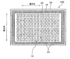
- a metal portion constituting the metal mask 10, that is, a portion other than one hole 16 may be provided along the outer edge of the vapor deposition mask 100 as shown in FIG. 6, and as shown in FIG.
- the size may be smaller than that of the resin mask 20 and the outer peripheral portion of the resin mask 20 may be exposed. Further, the size of the metal mask 10 may be made larger than that of the resin mask 20, and a part of the metal portion may protrude outward in the horizontal direction or in the vertical direction of the resin mask. In any case, the size of one hole 16 is smaller than the size of the resin mask 20.
- W1 and W2 have widths that can sufficiently satisfy durability and handling properties.
- an appropriate width can be appropriately set according to the thickness of the metal mask 10, as an example of a preferable width, both W1 and W2 are about 1 mm to 100 mm as in the metal mask in the vapor deposition mask of the embodiment (A). is there.
- the vapor deposition mask 100 of one embodiment prepares a metal mask with a resin plate in which a metal mask 10 having slits 15 provided on one surface of a resin plate is laminated, and then a metal mask with respect to the metal mask with a resin plate. It can be obtained by irradiating a laser through the slit 15 from the mask 10 side to form the opening 25 corresponding to the pattern to be deposited on the resin plate.
- a metal mask 10 provided with slits 15 is laminated on one surface of the resin plate.
- the material described in the resin mask 20 can be used for the resin plate.
- a masking member for example, a resist material is applied to the surface of the metal plate, a predetermined portion is exposed and developed, and finally the slit 15 is formed.
- a resist pattern is formed leaving the position to be formed.
- the resist material used as the masking member those having good processability and desired resolution are preferable.
- etching is performed by an etching method using this resist pattern as an etching resistant mask. After the etching is completed, the resist pattern is removed by washing. Thereby, the metal mask 10 provided with the slit 15 is obtained. Etching for forming the slit 15 may be performed from one side of the metal plate or from both sides.
- the slit 15 is formed in the metal plate using a laminate in which the resin plate is provided on the metal plate, a masking member is applied to the surface of the metal plate that is not in contact with the resin plate.
- a slit 15 is formed by etching from the side.
- the resin plate has etching resistance to the etching material of the metal plate, it is not necessary to mask the surface of the resin plate, but when the resin plate does not have resistance to the etching material of the metal plate. Needs to be coated with a masking member on the surface of the resin plate.
- the resist material is mainly described as the masking member. However, instead of coating the resist material, a dry film resist may be laminated and the same patterning may be performed.
- the resin plate constituting the metal mask with a resin plate may be not only a plate-like resin but also a resin layer or a resin film formed by coating. That is, the resin plate may be prepared in advance, and a resin layer or a resin film that finally becomes a resin mask can be formed on the metal plate by a conventionally known coating method or the like.
- the opening 25 can be formed by using a laser processing method, precision press processing, photolithography processing or the like on the metal mask with a resin plate prepared as described above.
- FIGS. 8A to 8C the tension auxiliary member 50 is stacked on one surface of the vapor deposition mask 100 (in the illustrated embodiment, the surface of the resin mask 20), and vapor deposition is performed.
- This is a step of fixing the tension assisting member 50 to the vapor deposition mask 100 in at least a part of the portion where the one surface of the mask 100 and the tension assisting member 50 overlap (reference numeral X in the drawing).
- FIG. 8 is a front view illustrating a state in which one surface of the vapor deposition mask and the tension assisting member 50 are fixed.
- the surface of the resin mask 20 of the vapor deposition mask 100 and the tension assisting member 50 overlap each other.
- the resin mask 20 and the tension assisting member 50 are fixed to the whole or a part of the overlapping portion.
- the tension assisting member 50 is disposed so as to overlap with one surface of the vapor deposition mask, and the entire overlapping portion or the overlapping portion is overlapped. In a part of the portion, one surface of the vapor deposition mask 100 and the tension auxiliary member 50 are fixed.
- the description of the openings provided in the resin mask 20 is omitted, and one screen composed of a plurality of openings is shown. “One screen” is as described in the vapor deposition mask of the embodiment (A) and the vapor deposition mask of the embodiment (B).
- the tension assisting member 50 is overlapped on one surface of the vapor deposition mask 100, and the vapor deposition mask 100 and the tension assisting member 50 are fixed in at least a part of the portion where the one surface of the vapor deposition mask and the tension assisting member 50 overlap. is doing. That is, the tension assisting member 50 can be fixed at any position as long as it satisfies the condition that it can be overlapped with the surface of the vapor deposition mask. Therefore, unlike the conventionally known gripping means, for example, a clamp that fixes the vapor deposition mask so as to sandwich the end of the vapor deposition mask, the position to fix the tension auxiliary member is not limited and is fixed to the vapor deposition mask 100 at an arbitrary position. be able to. In addition, the clamp etc. which hold
- pulling auxiliary member 50 is being fixed to the vapor deposition mask 100 in at least one part (code
- the vapor deposition mask 100 and the tension auxiliary member 50 may be fixed at all portions where one surface of the vapor deposition mask 100 and the tension auxiliary member 50 overlap.
- the tension assisting member may be fixed on the resin mask 20 as illustrated, or may be fixed on the metal mask 10.
- the vapor deposition mask with a frame finally obtained is normally fixed so that the metal mask 10 of the vapor deposition mask 100 and the frame face each other. Therefore, in consideration of this point, it is preferable that the auxiliary tension member 50 is fixed at least at a part overlapping the surface on the resin mask 20 side. If the tension assisting member 50 can be removed from the surface of the vapor deposition mask after the vapor deposition mask is fixed to the frame, there is no problem even if it is fixed at least partially overlapping the surface on the metal mask 10 side.
- the tension assisting member 50 only needs to be fixed on one surface of the vapor deposition mask 100 in at least a part of the portion overlapping the one surface of the vapor deposition mask 100 by any means, and the material thereof is not limited in any way. Absent.
- the tension assisting member 50 may be composed of a resin material or a metal material, and is composed of a material other than this, such as a glass material, a ceramic material, or a paper material. Also good.
- the tension auxiliary member 50 there is no limitation on the shape of the tension auxiliary member 50, and any shape can be used as long as one surface of the vapor deposition mask 100 and the surface of the tension auxiliary member can be fixed by some means. That is, the tension assisting member 50 may have any shape.
- the auxiliary tensile member 50 as an example has a sheet shape, a columnar shape, a prismatic shape, or the like.
- the vapor deposition mask 100 is pulled using the sheet-like tension auxiliary member as the tension auxiliary member 50, it is not limited to this form. Further, the size and thickness of the auxiliary tension member 50 are not limited in any way.
- the thickness and the like are not limited in any way.
- the surface of the tension assisting member 50 and the vapor deposition mask are in direct or indirect contact with each other, but there is no particular limitation on the form of contact, and the surface of the tension assisting member 50 and the vapor deposition mask are directly or indirectly in contact. It may be touched by a surface, or may be touched by a line or a point.
- the tensile auxiliary member 50 and one surface of the vapor deposition mask 100 are in direct or indirect contact with each other.
- the circumferential surface of the tension assisting member 50 and one surface of the vapor deposition mask are in direct or indirect contact with a line.
- the tension assisting member 50 is connected to driving means, and pulling the tension assisting member 50 by operating the driving means pulls the vapor deposition mask 100 fixed to the tension assisting member.
- driving means a conventionally well-known thing can be selected suitably, For example, a motor, an air cylinder, an electric actuator etc. can be mentioned.
- the vapor deposition mask 100 fixed to the tension auxiliary member 50 can be pulled without using the driving means.
- the vapor deposition mask fixed to the tension assisting member 50 can be pulled by pulling the tension assisting member 50 by hand. In this case, the tension assisting member 50 may not be connected to the driving unit.
- the one surface of the vapor deposition mask 100 and the tension assisting member 50 may be (i) fixed in direct contact with each other, or (ii) fixed in indirect contact with each other.
- a mode using a magnetic material as the tension assisting member 50 self-adhesiveness Examples include a mode using a material having a material, a mode using a material having self-adsorption property and removability, and a mode in which one surface of the vapor deposition mask 100 and the auxiliary tension member 50 are fixed using electrostatic adsorption or the like.
- a magnetic material is used as the tension auxiliary member 50
- vapor deposition is performed using magnetic force at a position where the tension auxiliary member 50 and the metal mask 10 overlap using the metal mask constituting the vapor deposition mask 100.
- the mask 100 and the tension auxiliary member 50 can be attracted and fixed. Further, when a material having self-adsorption and removability is used as the tensile auxiliary member 50, the tensile auxiliary member is used at the position where the tensile auxiliary member 50 and the surface of the vapor deposition mask overlap using the self-adsorption property. 50 can be fixed. According to the material having self-adsorption property and re-peelability, the tensile assisting member 50 can be fixed to the surface of the vapor deposition mask 100 even at a position where it does not overlap the metal mask 10 in the thickness direction.
- a material having magnetism and a material having self-adsorption property and removability are preferable materials because they can be used repeatedly.
- the self-adsorptive property of the tension assisting member means a property that allows close contact while retreating air when contacting the vapor deposition mask.
- the releasability of the tensile auxiliary member means a property that peeling can spread to the periphery and the entire tensile auxiliary member can be removed by lifting one end of the tensile auxiliary member fixed to the vapor deposition mask.
- Examples of the material having the self-adsorption property and the releasability include a self-adhesive resin such as silicon resin, polyolefin resin, and polyurethane-based thermoplastic elastomer, rubber, and polyvinyl chloride resin.
- Examples of self-adsorbing and re-peelable materials include commercial products such as Sumitomo Chemical Co., Ltd. trade name Sumilon S, Panac Co., Ltd. trade name olefin gel polymer sheet, and Fujikopian Co., Ltd. trade name FIXFILM. Goods can also be used.
- a material having magnetism or a material having self-adsorption property and removability can also be used in combination.
- the tension assisting member 50 a member constituted by a single member may be used, or a member constituted by combining a plurality of members may be used. Moreover, there is no limitation on the combination method in the case where a plurality of members are combined to form the tension assisting member, and the plurality of members may be arranged as the tension assisting member 50 arranged in any direction, and the plurality of members are stacked.
- the auxiliary tension member 50 may be used.
- the tension auxiliary member 50 in which a magnetic material is combined with a self-adsorptive material, a metal mask and an auxiliary frame 65 to be described later are temporarily fixed taking advantage of the characteristics of the magnetic material. Meanwhile, the vapor deposition mask 100 can be pulled. Moreover, when using the several tension
- the vapor deposition mask 100 and the tension auxiliary member 50 are indirectly connected using a predetermined member.
- the aspect which fixes regularly can be mentioned.
- the predetermined member include a pressure-sensitive adhesive, a pressure-sensitive adhesive sheet, and a material having magnetism and a material having self-adsorption and removability exemplified as the material of the auxiliary tension member 50.
- the predetermined member may be a member for indirectly connecting the vapor deposition mask and the tension assisting member 50, that is, a member that does not constitute the tension assisting member 50, and is used as a tension assisting member main body 50A described later. (See the tensile assisting member main body 50A in FIGS. 19A to 19D and 19F). In the latter case, the predetermined member constitutes the tension assisting member main body 50A, and the tension assisting member 50 described here constitutes the tension assisting member extension 50B.
- the predetermined member is preferably made of a material having a small elongation when the tension assisting member 50 is pulled.
- the material of the predetermined member that indirectly connects the vapor deposition mask and the tension auxiliary member 50 is preferably a material having a smaller elongation rate than the material constituting the resin mask 10 of the vapor deposition mask 100.
- the material of the predetermined member is a material having the same elongation rate as that of the material constituting the resin mask 10 or a material having a higher elongation rate, a material having a low elongation rate is used as the material of the predetermined member.
- the accuracy when pulling the vapor deposition mask tends to be low, but when pulling the tension assisting member 50, the predetermined member expands and contracts, and the degree of freedom of expansion and contraction of the predetermined member may be increased. it can.
- the degree of freedom of expansion / contraction of a predetermined member that indirectly connects the vapor deposition mask and the tension auxiliary member 50 is increased, the vapor deposition mask is pulled by the tension auxiliary member 50 and the vapor deposition mask is fixed to the frame.
- the external force generated in the above can be absorbed by a predetermined member.
- the elongation rate means the tensile elongation rate based on JISK7127 (1999).
- the distance from the surface of the vapor deposition mask 100 to the surface of the tension auxiliary member 50 can be increased by the thickness of a predetermined member, and the vapor deposition mask 100 and the tension auxiliary member 50 are indirectly connected. It is possible to suppress the tension auxiliary member 50 from coming into direct contact with the surface of the vapor deposition mask 100 at a place other than the fixed place in contact. For example, when the auxiliary tensile member 50 and the vapor deposition mask 100 are fixed in the fixing form (i) near the center of one surface of the vapor deposition mask, the tensile auxiliary member 50 is pulled when the tensile auxiliary member 50 is pulled.
- the surface of the vapor deposition mask and the tension auxiliary member 50 are in contact with each other. May damage the surface of the vapor deposition mask.
- the surface of the vapor deposition mask fixed to the tension auxiliary member 50 is a surface on the resin mask 20 side, and the tensile auxiliary member 50 made of a metal material harder than the resin mask material is an area other than the fixed portion. In this case, when the tension assisting member 50 is pulled, the tension assisting member 50 may damage the surface of the resin mask other than the fixed portion.
- the tension auxiliary member 50 that is directly fixed to one surface of one of the plurality of vapor deposition masks is pulled.
- the tension auxiliary member 50 is one of the other vapor deposition masks adjacent to the one vapor deposition mask in the width direction. It will also contact the surface of the surface.
- the tension assisting member 50 fixed to one vapor deposition mask is in contact with the surface of another vapor deposition mask, the surface of the other vapor deposition mask may be damaged. is there.
- a tension assisting member 50 made of a material that does not damage the surface of the vapor deposition mask, for example, a material such as resin.
- the tension auxiliary member 50 is fixed to the vapor deposition mask 100 in the fixing mode (ii), and the tension auxiliary member 50 is made of a material having a low elongation rate, for example, a metal material.
- a pulling auxiliary member 50 is used.
- the tension assisting member 50 itself is prevented from extending when the tension assisting member 50 is pulled while restraining the tension assisting member 50 from coming into contact with the surface of the vapor deposition mask 100. It is possible to pull the vapor deposition mask fixed to the auxiliary tension member with higher accuracy. Further, even when the fixing mode of (i) is adopted, as will be described later, the tension assisting member 50 is bent by the evaporation mask by bending the tension assisting member 50 (see FIGS. 19E and 19G). The contact with the surface of 100 can also be suppressed.
- the tension assisting member 50 has been described by taking the securing aspect of (i) and the securing aspect of (ii) as an example. And the tension assisting member extension 50B can also suppress various problems that may occur when the tension assisting member 50 is pulled.
- the tension auxiliary member main body 50A is a tension auxiliary member that is in contact with the surface of the vapor deposition mask 100 and is fixed to the vapor deposition mask 100 in at least a portion where the surface of the tension auxiliary member main body 50A and the surface of the vapor deposition mask 100 overlap.
- the tension auxiliary member extension 50B is a tension auxiliary member that is connected to the tension auxiliary member main body 50A and is not fixed to the surface of the vapor deposition mask 100.
- the tension assisting member 50 is made of a material such that the tension assisting member extension 50B hardly damages the surface of the vapor deposition mask, such as a resin.
- 19 (a) and 19 (f) show a tension assisting member main body 50A and a tension assisting member extension 50B, and a tension assisting member main body 50A. It is a schematic sectional drawing which shows an example of the state fixed in the at least one part which the surface of the vapor deposition mask 100 overlaps. In the form shown in FIGS. 19A and 19F, another vapor deposition mask 100A adjacent to the one vapor deposition mask 100 is positioned in the width direction of one vapor deposition mask 100, and a tensile assisting member extension portion is provided.
- the tension assisting member extension 50B is in contact with the surface of another vapor deposition mask 100A.
- the tension assisting member extension 50B is connected to the driving means 55, and by operating the driving means 55, one vapor deposition mask 100 fixed to the tension assisting member 50 is pulled. .
- FIGS. 19B to 19D show a tension auxiliary member 50 composed of a tension auxiliary member main body 50A and a tension auxiliary member extension 50B, one vapor deposition mask 100, and a tension auxiliary member main body 50A. It is a schematic sectional drawing which shows another example of the state fixed in at least one part of the part which the surface of the vapor deposition mask 100 overlaps. Similarly to FIGS. 19A and 19F, in the width direction of one vapor deposition mask 100, another vapor deposition mask 100A adjacent to the one vapor deposition mask 100 is located. In the form shown in FIG. 19B, the surface of another vapor deposition mask 100A adjacent to one vapor deposition mask 100 is not in contact with the tension assisting member extension 50B.
- the tension assisting member 50 composed of the tension assisting member main body 50A and the tension assisting member extension 50B exhibits a stepped shape in cross section as a whole.
- the surface of another vapor deposition mask 100A adjacent to one vapor deposition mask 100 is not in contact with the extension auxiliary member extension 50B. Therefore, according to the form shown in FIGS. 19B to 19D, it is possible to suppress damage to the surface of the other vapor deposition mask 100A regardless of the material of the extension assisting member extension 50B.
- the tension assisting member extension 50B In the case where the surface of the other vapor deposition mask 100A is not in contact with the tension assisting member extension 50B, it is preferable to use a material having a low elongation rate, such as a metal material, as the tension assisting member extension 50B. .
- a material having a low elongation rate such as a metal material
- the extension auxiliary member extension 50B made of a metal material or the like the extension of the extension auxiliary member 50 itself when the extension auxiliary member 50 is pulled can be suppressed, and the vapor deposition mask is pulled more accurately. be able to.
- the cross-sectional shape of the tension assisting member extension 50B is stepped, and the area where the tension assisting member extension 50B is in contact with the surface of another adjacent vapor deposition mask 100A is reduced.
- connect it can also suppress that the position of other vapor deposition mask 100A fluctuates.
- a material that can be bent and can maintain the bent shape for example, A thin metal plate or the like can be used.
- Specific examples include a leaf spring and a bracket.
- the tension assisting member body 50A and the tension assisting member extension 50B have substantially the same thickness, but may have different thicknesses.
- the width of the tension assisting member main body 50A may be larger, smaller or the same as the width of the tension assisting member extension 50B (the same width in the illustrated embodiment).
- the shape of the tension assisting member main body 50A and the shape of the tension assisting member extension 50B may be different. For example, in the form shown in FIG. 19A, the tension assisting member main body 50A is formed into a sheet shape and the tension assisting member extension 50B is formed into a columnar shape so that one vapor deposition mask and the tension assisting member main body 50A are formed.
- the tension auxiliary member 50 is one vapor deposition mask.
- the influence on the other vapor deposition mask 100A adjacent to 100 can be reduced.
- the tension auxiliary member main body 50A and the vapor deposition mask 100 may be directly fixed or indirectly fixed.
- the tensile assisting member 50 is bent so that the cross-sectional shape is stepped, and the surface of the other vapor deposition mask 100A adjacent to the vapor deposition mask 100 is stretched. It is also possible to reduce the area where the auxiliary member 50 does not contact or is in contact.
- the tensile auxiliary member 50 shown in FIGS. 19 (e) and 19 (g) has a configuration in which one tensile auxiliary member is bent.
- one vapor deposition mask 100 in the case where a plurality of vapor deposition masks are arranged in the width direction of the vapor deposition mask, another vapor deposition mask 100A adjacent to the one vapor deposition mask 100, and the tension auxiliary member 50.
- the tension assisting member 50 is fixed at least at a part of the portion in contact with the surface of the single vapor deposition mask in the vicinity of the center of the single vapor deposition mask, FIG.
- the various forms described can be appropriately selected and used. In the embodiment described with reference to FIG.
- the fixing position of the one surface of the vapor deposition mask 100 and the auxiliary tensile member 50 is not limited in any way, and can be fixed at an arbitrary position.
- the present invention unlike the gripping means for gripping the end of the vapor deposition mask, can be fixed at any position where the tension assisting member and the vapor deposition mask overlap, and can be placed at any position on the surface of the vapor deposition mask.
- the vapor deposition mask 100 and the tension auxiliary member 50 can be fixed.
- the material of the tension auxiliary member, the application area of the adhesive, and the like the area of the portion where the tension auxiliary member 50 and the vapor deposition mask are fixed can be freely set.
- the fixing position will be described in detail with a specific example in the first tension step described later.
- the vapor deposition mask is fixed to the frame 60 in a stretched state. Therefore, the fixation between the tension auxiliary member 50 and one surface of the vapor deposition mask is performed by fixing the vapor deposition mask to the frame. It is preferably fixed at a position where it does not interfere.
- a form for fixing the frame and the vapor deposition mask at a position that does not hinder the fixation of the vapor deposition mask a form for fixing the tension auxiliary member 50 on one surface of the vapor deposition mask, avoiding a predetermined position where the vapor deposition mask and the frame are fixed, The form using the tension
- FIGS. 9A to 9E can be exemplified.
- 9 (a) and 9 (b) one surface of the vapor deposition mask 100 and the auxiliary tension member 50 are fixed on the outer side of the fixed fixing position with the frame, and FIGS. 9 (c) to 9 (e). Then, a part of the tension
- the removal of the tension assisting member 50 may be performed by notching the tension assisting member 50 as shown in FIGS. 9C and 9D.
- the tension assisting member 50 may be removed. You may carry out by hollowing out.
- the notch shape for removing a part of the tension assisting member 50 and the cut-out shape are not limited to the illustrated form, and may be any shape.
- the tension assisting member is cut out in a circular shape, but may be cut out in a polygonal shape or other shapes. The same applies to the notch shape.
- the tension assisting member 50 when pulling with a plurality of tension assisting members 50, the tension assisting member 50 can be fixed on one surface of the vapor deposition mask while avoiding the position to be fixed to the frame.
- a welding fixing method using a laser beam is used to fix the frame and the vapor deposition mask. Therefore, as in the latter embodiment, by using the tension assisting member 50 formed of a transparent material, that is, the tension assisting member 50 that does not absorb the laser light, the position where the vapor deposition mask and the frame are fixed is fixed. Even when the tension assisting member is located in a portion overlapping with the laser beam, the deposition mask and the frame can be fixed by irradiating the laser beam through the tension assisting member 50. Further, in this embodiment, since the tension assisting member 50 formed using a transparent material is used, it is scheduled to be fixed to the frame without disturbing the visibility of the planned position where the vapor deposition mask and the frame are fixed. This is a preferred form in that the deposition mask and the frame can be fixed while looking at the position.
- the fixing strength between the vapor deposition mask 100 and the auxiliary tensile member 50 is not particularly limited, and may be appropriately set according to the tension when the auxiliary tensile member 50 is pulled in the first tensile step described later. Specifically, it is sufficient that the tension assisting member 50 is fixed at such a strength that the tension assisting member 50 is not detached from the vapor deposition mask 100 by the tension when the tension assisting member 50 is pulled.
- the first tensioning step is fixed to the tension assisting member 50 by pulling the tension assisting member 50 that is secured at least at a part of the portion overlapping the surface of the vapor deposition mask 100 in the tension assisting member fixing step.
- the deposition mask 100 is pulled.
- the direction in which the tension assisting member 50 is pulled and the longitudinal direction of the vapor deposition mask 100 (for example, the horizontal direction shown in FIG. 1), the width direction (for example, the vertical direction shown in FIG. 1), or other directions, For example, it may be pulled in any direction such as an oblique direction.
- the tension auxiliary member 50 and the vapor deposition mask can be fixed at an arbitrary position on one surface of the vapor deposition mask, and a tension using a clamp or the like that grips the end of the conventional vapor deposition mask. It can be easily pulled in directions other than the longitudinal direction and the width direction of the vapor deposition mask, which is difficult with the means.
- “pulling the vapor deposition mask” refers to pulling the auxiliary tensile member 50 fixed to the vapor deposition mask and extending an external force (tensile force) in the direction of extending the vapor deposition mask 100 fixed to the tensile auxiliary member 50. ).
- “pulling the vapor deposition mask” means applying an external force (tension) in the direction of extending the vapor deposition mask 100 fixed to the tension auxiliary member 50 using the tension auxiliary member 50.
- the direction of extending the vapor deposition mask is a concept including not only the direction of extending the opening 25 provided in the resin mask of the vapor deposition mask but also the direction of contracting the opening 25 provided in the resin mask of the vapor deposition mask. .
- FIGS. 8A and 8B an opening provided in one screen of the resin mask of the vapor deposition mask 100 by pulling each of the tension assisting members 50 outward of the vapor deposition mask 100.
- Each part extends in the width direction.
- the tension assisting member 50 can be pulled to change the position of the opening 25 and to eliminate distortion and deflection generated in the resin mask 20 without substantially changing the size of the opening 25 itself.
- the angle formed by the surface of the vapor deposition mask 100 and the axis in the direction of pulling the tension auxiliary member is not particularly specified.
- the angle formed between the surface and the axis in the direction of pulling the tension auxiliary member is fixed to the vapor deposition mask so that it is within the range of 0 ° ⁇ 89 °, preferably 0 ° ⁇ 45 °, more preferably 0 ° ⁇ 10 °.
- the pulling auxiliary member 50 is pulled. According to this embodiment, when the auxiliary tension member 50 is pulled, the vapor deposition mask 100 fixed to the auxiliary tensile member 50 can be prevented from being distorted or bent.
- the surface of a vapor deposition mask means the surface of the vapor deposition mask corresponding to the area
- the surface of the vapor deposition mask 100 is used.
- the axis in the direction of pulling the auxiliary tension member is in the range of 0 ° ⁇ 89 °, preferably 0 ° ⁇ 45 °, more preferably 0 ° ⁇ 10 °, and with respect to the reference angle
- the pulling auxiliary members 50 are preferably pulled within a range of ⁇ 10 °, preferably ⁇ 5 °.
- the reference angle referred to here is an arbitrary angle.
- each of the tension assisting members 50 is ⁇ 10 °, particularly 30 ° ⁇ 5 °.
- each of the auxiliary tension members 50 is pulled at an angle within the above preferable range so as to be ⁇ 10 °, preferably ⁇ 5 ° with respect to the reference angle, distortion of the vapor deposition mask 50,
- the vapor deposition mask 100 can be pulled in a state where the occurrence of bending or the like is suppressed.
- the first tensioning step will be described with reference to the fixing position between the vapor deposition mask 100 and the tension auxiliary member 50.
- FIG. 10 is a front view illustrating a first tensioning process according to an embodiment.
- FIG. 10A two sides (on the illustrated form) that are on one surface of the vapor deposition mask and are opposed to each other.
- the tension auxiliary members are fixed one by one, and each of the tension auxiliary members 50 thus fixed is pulled outward (in the direction of the arrow in the drawing) of the vapor deposition mask.
- the vapor deposition mask fixed to 50 is pulled.
- the tension assisting members 50 are fixed one by one on one surface of the vapor deposition mask and in the vicinity of two opposite sides (longitudinal sides in the illustrated form) of the vapor deposition mask.
- FIG. 10C is a combination of FIGS. 10A and 10B.
- FIGS. 10A to 10C show a form in which the vapor deposition mask 100 fixed to the tension assisting member 50 is pulled using the tension assisting member 50 instead of a conventionally known clamp or the like.
- a plurality of auxiliary tensile members 50 are fixed in the vicinity of the end portion on one surface of the vapor deposition mask, and the auxiliary auxiliary members 50 are used to The vapor deposition mask 100 fixed to the tension auxiliary member 50 may be pulled.
- the plurality of auxiliary pulling members 50 are fixed in the vicinity of the end on one surface of the vapor deposition mask, so that the vapor deposition mask can be pulled more accurately.
- the tension assisting member 50 is provided at both the position overlapping with one screen and the position not overlapping with one screen in the width direction of the vapor deposition mask 100 (vertical direction in the drawing). Is fixed, and the vapor deposition mask can be pulled with higher accuracy by appropriately setting the tension value or the pulling amount when pulling each tension assisting member.
- a plurality of tension assisting members 50 are provided on one surface of the vapor deposition mask and in the vicinity of the ends of two opposite sides (sides in the width direction in the illustrated form) of the vapor deposition mask. Is fixed, and the vapor deposition mask is pulled by pulling each tension auxiliary member 50 outward (in the direction of the arrow in the drawing) of the vapor deposition mask.
- FIG. 11A a plurality of tension assisting members 50 are provided on one surface of the vapor deposition mask and in the vicinity of the ends of two opposite sides (sides in the width direction in the illustrated form) of the vapor deposition mask. Is fixed, and the vapor deposition mask is pulled by pulling each
- FIG.11 (c) is the form which combined Fig.11 (a) and (b). Moreover, it can also be set as the form which combined the form shown in FIG. 10, FIG. 11 suitably.
- 20 (a) and 20 (b) are modifications of FIG. 11 (a). In FIG. 20 (a), the vapor deposition mask 100 is pulled to a position overlapping one screen in the width direction (vertical direction in the drawing).
- the auxiliary member 50 is fixed.
- the tensile auxiliary member 50 is fixed at a position that does not overlap one screen in the width direction of the vapor deposition mask 100 (the vertical direction in the drawing).
- the modification shown in FIG. 20 can be a combination with the form shown in each figure, for example, the form shown in FIG.
- the form shown to Fig.11 (a), (c) is a preferable form at the point which can eliminate the shape and dimension fluctuation which arose in the opening part 25 which comprises 1 screen accurately.
- the tension assisting member 50 is fixed on one surface of the vapor deposition mask 100 and in the vicinity of the ends of the two opposite sides of the vapor deposition mask.
- the tension assisting member may be fixed only in the vicinity of the end of one of the two opposing sides of the vapor deposition mask, and the vapor deposition mask may be pulled. That is, one of the two opposing sides may be a fixed end, the tension assisting member 50 may be fixed near the end of the other one, and the tension assisting member may be pulled. Further, even if one of the two opposite sides is gripped by a conventionally known gripping means such as a clamp, and the tension assisting member 50 is fixed on one surface of the vapor deposition mask near the end of the other side. Good.
- FIG. 12A shows a drive in which two opposite end portions (longitudinal end portions in the illustrated form) of the vapor deposition mask 100 are held by a gripping means 80 such as a clamp and connected to the gripping means. It is a front view which shows the state which act
- Examples of the driving means connected to the gripping means include a motor, an air cylinder, and an electric actuator. As shown in FIG.
- FIG. 12A shows an opening arranged in one screen due to shrinkage of the vapor deposition mask that occurs when the vapor deposition mask 100 is pulled in the first direction (in the illustrated form, the longitudinal direction of the vapor deposition mask). This shows a state in which the shape and dimensions of the portion (not shown) are fluctuating.
- one screen is used to schematically show that the shape and dimensions of the opening are fluctuating. Is described as a distorted shape.
- region which becomes the rectangular one screen in FIG.12 (c) has eliminated the fluctuation
- the auxiliary tension member 50 fixed to one surface of the vapor deposition mask 100 is different from the first direction.
- the pulling is in the second direction (in the form shown, the width direction of the vapor deposition mask), and as shown in FIG. 12C, the shape of the opening and the variation in dimensions caused by pulling in the first direction. Has been eliminated.
- pulling of the vapor deposition mask using the auxiliary pulling member 50 may be performed after the vapor deposition mask is pulled in the first direction using the gripping means. It may be done while pulling in the direction.
- the first direction is not particularly limited, but when the deposition mask is pulled using a conventionally known gripping means or the like, the first direction is usually the longitudinal direction or the width direction of the deposition mask 100. It becomes.
- the first direction may be any direction. That is, in the manufacturing method of the vapor deposition mask with a frame according to an embodiment, the vapor deposition mask is pulled in advance by using a conventionally known gripping means or the like before or at the same time as the first tensioning step. A second tension step may be included.
- pulling in the first direction and the pulling in the second direction may be performed using only the auxiliary pulling member 50 without using a gripping means such as a clamp (see FIG. 11C). Further, pulling in the first direction using the tension assisting member 50 and pulling in the second direction may be performed at the same time, and pulling in the first direction using the tension assisting member 50 was performed. Later, pulling in the second direction using the tension assisting member 50 may be performed.
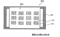
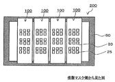
- a vapor deposition mask 200 with a frame shown in FIG. 15 is formed by fixing one vapor deposition mask 100 to a frame 60.
- a plurality of vapor deposition masks (four vapor deposition masks in the illustrated embodiment) are fixed to the frame 60 in the longitudinal direction or in the width direction (in the illustrated embodiment, in the width direction). Are fixed side by side).
- the vapor deposition mask with a frame shown in FIG. 15 has only one vapor deposition mask fixed to the frame, as shown in FIG. 13A, the longitudinal direction end portion and the width direction end portion of the vapor deposition mask are arranged. It can be easily gripped by the gripping means, and the deposition mask can be easily pulled in both the longitudinal direction and the width direction.
- FIG. 13A in a partial area of the vapor deposition mask (in one screen indicated by symbol A in the drawing), the shape of all or a part of the openings located in the partial area.
- the variation in the opening occurs on one surface of the vapor deposition mask 100.
- FIG.13 (a) is a front view which shows an example of a vapor deposition mask when the 2nd tension
- FIG. 13B is a front view of the vapor deposition mask showing an example of a state in which the auxiliary tensile member fixing step is performed after the second tensile step.
- FIG.13 (c) is a front view which shows an example of the vapor deposition mask by which the fluctuation
- the member 50 is fixed, but on one surface of the vapor deposition mask 100, all or part of the portion where the region constituting one screen and the tension assisting member 50 overlap, and one surface of the vapor deposition mask 100,
- the tension assisting member 50 can also be fixed (not shown). That is, one surface of the vapor deposition mask 100 and the auxiliary tension member 50 can be fixed within one screen.
- the fixing position for fixing one surface of the vapor deposition mask and the auxiliary tensile member is a mode in which the entire vapor deposition mask is pulled, a mode in which the entire screen is pulled, and a plurality of openings provided in the screen. It can be appropriately set according to the form or the form of individually pulling the opening 25 provided in one screen, and the fixing position is not limited in any way.
- a plurality of vapor deposition masks are arranged and fixed on the frame 60 in the longitudinal direction or the width direction of the vapor deposition mask (in the illustrated form, they are arranged and fixed in the width direction of the vapor deposition mask).
- the longitudinal direction or widthwise end of the vapor deposition mask (in the form shown, the longitudinal end of the vapor deposition mask) ) Can be easily gripped by the gripping means, but due to the presence of the vapor deposition mask adjacent to one vapor deposition mask, an end portion in the adjacent direction (in the form shown, the edge in the width direction of the vapor deposition mask) Part) is difficult to grip by the gripping means. That is, it is difficult to obtain a multi-sided evaporation mask with a frame by pulling the evaporation mask in both the longitudinal direction and the width direction using the gripping means.
- the manufacturing method of the vapor deposition mask with a frame overlaps the tension auxiliary member 50 on one surface of the vapor deposition mask, the one surface of the vapor deposition mask and the tension auxiliary member 50, In at least a part of the overlapping portion, the tension assisting member 50 is fixed to one surface of the vapor deposition mask and the tension assisting member 50 is used, that is, by pulling the fixed tension assisting member 50, The vapor deposition mask fixed to the tension auxiliary member is pulled. Therefore, as shown in FIG.
- the one vapor deposition mask 100 Even if there is no gap between one vapor deposition mask 100 and another vapor deposition mask 100A adjacent to the one vapor deposition mask or the gap is small, the one vapor deposition mask 100
- the tensile assisting member 50 fixed to one surface of the vapor deposition mask can be pulled also to the adjacent vapor deposition mask direction side, and when forming a multi-surface vapor deposition mask with a frame, the longitudinal direction of the vapor deposition mask, and Biaxial tension in the width direction can be performed.
- the manufacturing method of one embodiment of the present invention when a multi-sided evaporation mask with a frame is used, the interval between adjacent evaporation masks can be made extremely small.
- the vapor deposition masks other than the vapor deposition mask 100 are described as being fixed to the frame at a position indicated by a symbol Y in the drawing.
- a second tensioning step of pulling the vapor deposition mask 100 in the first direction (the longitudinal direction of the vapor deposition mask in the illustrated form) using the gripping means is performed before the first tensioning step.
- the shape and size of the openings constituting one screen of the vapor deposition mask 100 are changed.
- by pulling to the adjacent vapor deposition mask direction side the width direction of the vapor deposition mask
- the adjacent vapor deposition mask directions are not limited to the direction orthogonal to the first direction, and are at a certain angle with respect to the axis in the orthogonal direction, for example, 0 ° ⁇ 45 °, 0 °.
- the angle may be about ⁇ 30 ° or 0 ° ⁇ 5 °.
- a frame 60 having a through-hole formed therein, the frame portion of the frame 60, and the metal mask 10 of the vapor deposition mask in a state of being pulled in the first tensioning process Is a step of fixing the vapor deposition mask 100 in a state of being overlapped so as to face each other and being pulled in the first pulling step to the frame 60.
- the frame 60 and the vapor deposition mask 100 are fixed at a position where the frame 60 and the metal part of the vapor deposition mask are in contact with each other, and the position is not particularly limited.
- FIG. 15 is a front view of a vapor deposition mask with a frame in which one vapor deposition mask is fixed to the frame 60 as viewed from the resin mask side.
- FIG. 16 is a front view of a multi-side vapor deposition mask 200 with a frame in which a plurality of vapor deposition masks 100 are fixed to the frame 60 in the longitudinal direction or the width direction (in the illustrated form, fixed in the width direction) as viewed from the resin mask side.
- FIG. 16 is a front view of a multi-side vapor deposition mask 200 with a frame in which a plurality of vapor deposition masks 100 are fixed to the frame 60 in the longitudinal direction or the width direction (in the illustrated form, fixed in the width direction) as viewed from the resin mask side.
- the frame 60 is a substantially rectangular frame member, and has a through hole for exposing the opening 25 provided in the resin mask 20 of the vapor deposition mask 100 to be finally fixed to the vapor deposition source side.
- a metal material having high rigidity for example, SUS, Invar material, ceramic material, or the like can be used.
- the metal frame is preferable in that it can be easily welded to the metal mask of the vapor deposition mask and the influence of deformation or the like is small. The same applies to the material of the following reinforcing frame 65.
- the thickness of the frame is not particularly limited, but is preferably about 10 to 30 mm from the viewpoint of rigidity.
- the width between the inner peripheral end face of the opening of the frame and the outer peripheral end face of the frame is not particularly limited as long as the frame and the metal mask of the vapor deposition mask can be fixed. The width can be exemplified.
- a reinforcing frame 65 or the like is provided in the through hole region within a range that does not hinder the exposure of the opening 25 of the resin mask 20 constituting the vapor deposition mask 100.
- a frame 60 may be used.
- the frame 60 and the vapor deposition mask 100 can be fixed using the reinforcing frame 65.
- the frame 60 and the reinforcing frame 65 may be made of the same material or different materials.
- the vapor deposition mask with the frame shown in FIG. 16 is formed through the first pulling step described above, after the pulling in the first direction and the second direction is performed at the same time, It is necessary to fix the vapor deposition mask in a pulled state. This is after pulling in the first direction (for example, the longitudinal direction of the vapor deposition mask) and in a second direction (for example, the width direction of the vapor deposition mask) different from the first direction. If the vapor deposition mask that has been pulled in the first direction is fixed to the frame 60 before pulling, the frame 60 and the vapor deposition mask 100 are completely fixed at this stage.
- the first direction for example, the longitudinal direction of the vapor deposition mask
- a second direction for example, the width direction of the vapor deposition mask
- the second direction Even if a pull in a second direction different from the first direction is performed in order to eliminate variations in the shape and dimensions of the opening that may be caused by pulling in the first direction, the second direction This is because the vapor deposition mask 100 cannot be fixed to the frame 60 while maintaining the state of being pulled.
- the vapor deposition mask is pulled in the first direction (for example, the longitudinal direction of the vapor deposition mask), and the main body of the frame 60 is moved in the first direction. Even after the tensioned deposition mask 100 is fixed, it is possible to fix the frame 60 and the deposition mask 100 again using the reinforcing frame 65 (see FIG. 18).
- the above The vapor deposition mask that has been pulled by the first tensioning step after the first tensioning step described in step 1 is pulled in the second direction that is different from the first direction. It becomes possible to fix using 65. That is, by using a frame having a reinforcing frame, after obtaining a vapor deposition mask with a frame in which the vapor deposition mask is fixed to the main body of the frame 60, a region in which the shape and dimensions of the opening have changed are generated.
- the tension assisting member 50 is fixed in the vicinity, and the tension assisting member 50 is pulled, whereby the tensioned vapor deposition mask can be fixed using the reinforcing frame 65.
- the tension assisting member fixing step and the first tensioning step can be applied as a method for finely adjusting the fluctuation of the opening that may occur after obtaining the vapor deposition mask with a frame. Fine adjustment of the fluctuation of the opening may be performed by pulling in the direction in which the opening 25 is extended, or by pulling in which the opening 25 is contracted.
- the main body of the frame referred to here means a portion different from the reinforcing frame 65, that is, an outer frame.
- the vapor deposition mask 100 is fixed to the main body portion of the frame 60 in a state where the vapor deposition mask 100 is pulled in the first direction, and then the fixed vapor deposition mask is removed using the first tensioning step described above. Further, the vapor deposition mask 100 is fixed to the reinforcing frame 65 of the frame 60 by pulling in a second direction different from the first direction. However, instead of this form, first, the first tension described above is used. Using the process, the vapor deposition mask is pulled to fix the vapor deposition mask 100 to the reinforcement frame 65 of the frame 60, and then the vapor deposition mask fixed to the reinforcement frame 65 is pulled in a direction different from the direction in which the vapor deposition mask was previously pulled. Thus, the vapor deposition mask may be fixed to the main body portion of the frame 60. In addition, the vapor deposition mask may be fixed to the main body portion of the frame 60 and the reinforcing frame 65 after pulling in the first direction and the second direction.
- the pulling in the first direction and the pulling in the second direction may be performed by the first pulling process, or the pulling in either direction may be performed by the first pulling process.
- the pulling in the first direction may be performed by the second pulling step using the gripping means or the like, and the pulling in the second direction may be performed by the first pulling step.
- the pulling in the first direction may be performed by the first tensioning step, and the pulling in the second direction may be performed by the second tensioning step.
- the vapor deposition mask is pulled in the first direction by the second tension process using the gripping means or the like before the first tension process, and after the second tension process, by the first tension process.
- the tension auxiliary member By pulling the tension auxiliary member, the vapor deposition mask fixed to the tension auxiliary member is pulled in the second direction.
- pulling in the first direction by the second pulling process using a gripping means or the like and pulling in the second direction by the first pulling process are simultaneously performed.
- the frame 60 provided with the reinforcing frame 65 may be obtained, for example, by integrally forming the main body portion of the frame 60 and the reinforcing frame 65 of the frame 60. Further, it may be obtained by fixing the reinforcing frame 65.
- the grid-like reinforcing frame 65 as shown in FIG. 17C may be an integrated type obtained by processing a metal plate or the like, and has a plurality of reinforcing frames 65 incorporated vertically and horizontally. Also good. In the latter case, when a plurality of vapor deposition masks are arranged side by side in the width direction of the frame 60 (lateral direction in FIG. 17C), the direction orthogonal to the direction of the adjacent vapor deposition mask (lateral direction in the figure).
- the reinforcing frame 65 extending in the (vertical direction in the figure) is incorporated so that the reinforcing frame 65 is in contact with the vapor deposition mask, in other words, the reinforcing frame 65 extending in the direction perpendicular to the direction of the adjacent vapor deposition mask is positioned on the upper side. preferable.
- the reinforcing frame 65 extending in the direction of the adjacent vapor deposition mask is incorporated so as to be positioned above the reinforcing frame 65 extending in the direction orthogonal to the direction of the adjacent vapor deposition mask.
- the reinforcing frame 65 is not limited to the illustrated form, and may be a combined form of a plurality of reinforcing frames 65 extending in a random direction.
- the first tensioning step can be performed in a state where the vapor deposition mask 100 is temporarily fixed to the main body of the frame 60 or the reinforcing frame 65.
- Temporary fixing is performed by placing a magnetic member such as a magnetic plate or a magnet sheet on the surface of the frame 60 that does not contact the vapor deposition mask 100 or the surface of the vapor deposition mask 100 that does not contact the frame. This can be performed by attracting the vapor deposition mask 100 and the main body of the frame 60 or the reinforcing frame 65.
- the vapor deposition mask in the state in which the tension in the first direction is performed is temporarily fixed to the main body portion of the frame 60 or the reinforcing frame 65, and the first tensioning process is performed.
- the vapor deposition mask with a frame can be obtained by pulling the vapor deposition mask in a temporarily fixed state and welding and fixing the frame 60 and the vapor deposition mask after the first pulling step.
- a tension assisting member 50 made of a material having magnetism or a tension assisting member 50 in which a material having magnetism is combined with another material, for example, a material having self-adsorptivity, a separate magnetism is used.
- the tension assisting member 50 itself is temporarily fixed to the vapor deposition mask 100 by the tension assisting member 50 while temporarily fixing the reinforcing frame 65 of the frame 60 and the deposition mask 100 using the magnetism of the tension assisting member 50 itself. You can also pull. That is, the tension auxiliary member 50 in this case plays both the role of temporarily fixing the vapor deposition mask and the frame and the role of pulling the vapor deposition mask. By performing the temporary fixing, it is possible to suppress a positional shift or the like that may be caused by pulling the vapor deposition mask, and it is possible to pull the vapor deposition mask with higher accuracy.
- the vapor deposition mask in a state in which the pulling in the first direction is performed is fixed to the main body of the frame 60 by welding, Next, the vapor deposition mask that is welded and fixed to the main body portion of the frame 60 is temporarily fixed to the reinforcing frame 65, and then the vapor deposition mask that has been fixed to the main body portion of the frame 60 and temporarily fixed to the auxiliary frame 65.
- tensile_strength process can also be performed. Also by this method, it is possible to suppress a positional shift or the like that may be caused by pulling the vapor deposition mask by temporary fixing, and it is possible to pull the vapor deposition mask with higher accuracy.
- each reinforcing frame 65 when the lattice-shaped reinforcing frame 65 having the form shown in FIG. 17C is used, and all the reinforcing frames 65 may have the same width.
- the width can be changed every time. Note that when arranging a plurality of vapor deposition masks side by side, in order to increase the number of vapor deposition masks assigned to the frame, it is necessary to reduce the interval between adjacent vapor deposition masks. When the interval between the adjacent vapor deposition masks is reduced, it is necessary to reduce the width of the reinforcing frame 65 extending in the direction orthogonal to the direction of the adjacent vapor deposition mask.
- the rigidity of the reinforcing frame 65 extending in the direction orthogonal to the direction of the adjacent vapor deposition mask decreases, and the direction orthogonal to the direction of the adjacent vapor deposition mask.
- the vapor deposition mask is fixed to the reinforcing frame 65 extending in the direction, deformation or the like is likely to occur.
- the width of the reinforcing frame 65 extending in the direction orthogonal to the direction of the adjacent vapor deposition mask is larger than this width. It is preferable to do.
- the rigidity of the entire reinforcement frame 65 can be increased.
- the width of the reinforcing frame 65 extending in the direction of the adjacent vapor deposition mask is larger than the width of the reinforcing frame 65 extending in the direction orthogonal to the direction of the adjacent vapor deposition mask.
- the width of the reinforcing frame 65 extending in the direction orthogonal to the direction of the adjacent vapor deposition mask is about 0.5 mm to 50 mm, and the width of the reinforcing frame 65 extending in the direction of the adjacent vapor deposition mask is 0.5 mm. About 50 mm.
- the reinforcing frame 65 of a preferable form is such that the width of the reinforcing frame 65 extending in the direction orthogonal to the direction of the adjacent vapor deposition mask and the width of the reinforcing frame 65 extending in the direction of the adjacent vapor deposition mask are within the range exemplified above. In addition, the relationship that the width of the reinforcing frame 65 extending in the direction of the adjacent vapor deposition mask is larger than the width of the reinforcing frame 65 extending in the direction orthogonal to the direction of the adjacent vapor deposition mask is satisfied.
- An example of the thickness of the reinforcing frame 65 is about 0.01 mm to 30 mm.
- the surface positions of the main body portion and the reinforcing frame 60 can be matched.
- grooves or the like may be appropriately provided in the reinforcing frames 65 so that the surface positions of the reinforcing frames 65 are the same. it can.
- the fixing method is not particularly limited, and can be fixed using various known welding methods such as laser welding, arc welding, electric resistance welding, and electron beam welding, adhesives, screwing, and the like.
- the tension assisting member 50 fixed on one surface of the vapor deposition mask 100 is removed from the vapor deposition mask, whereby the vapor deposition with a frame in which the vapor deposition mask is fixed to the frame. Get a mask.
- the vapor deposition mask pulling method according to an embodiment of the present invention is formed by laminating a metal mask having a slit and a resin mask having an opening corresponding to a pattern to be vapor deposited at a position overlapping the slit.
- the vapor deposition mask tensioning method of an embodiment of the present invention the vapor deposition mask can be pulled by a simple method, and even in a situation where another vapor deposition mask is adjacent to the vapor deposition mask.
- the vapor deposition mask fixed to the tension auxiliary member can be pulled in the direction side of the other vapor deposition mask.
- the first tensioning step is performed in advance in the first direction, for example, in the longitudinal direction or the width direction of the vapor deposition mask, using a gripping means or the like. This is performed after pulling, and in the first pulling step, the pulling auxiliary member is pulled in a second direction different from the first direction pulled in advance, for example, in a direction orthogonal to the first direction. That is, before the first pulling step, a second pulling step of pulling the vapor deposition mask in the first direction using a gripping means or the like may be further included. Moreover, you may perform a 1st tension process and a 2nd tension process simultaneously.
- the tension auxiliary member fixing step and the first tension step As the tension auxiliary member fixing step and the first tension step, the tension auxiliary member fixing step and the first tension step described in the vapor deposition mask with a frame according to the embodiment of the present invention can be applied as they are. Description is omitted.
- the manufacturing method of the organic-semiconductor element of one Embodiment of this invention has the process of forming a vapor deposition pattern by the vapor deposition method using a vapor deposition mask with a flame
- the manufacturing method of the said invention in the process of manufacturing the said organic-semiconductor element It is characterized in that the vapor deposition mask with a frame of one embodiment manufactured by is used.
- An organic semiconductor device manufacturing method having a step of forming a vapor deposition pattern by a vapor deposition method using a vapor deposition mask with a frame includes an electrode forming step of forming an electrode on a substrate, an organic layer forming step, and a counter electrode forming step.
- the deposition pattern is formed on the substrate by a deposition method using a deposition mask with a frame in each optional step. For example, when the vapor deposition method using a vapor deposition mask with a frame is applied to the R, G, B light emitting layer forming step of the organic EL device, vapor deposition patterns of the respective color light emitting layers are formed on the substrate.
- the manufacturing method of the organic-semiconductor element of one Embodiment of this invention is not limited to these processes, It is applicable to the arbitrary processes in manufacture of the conventionally well-known organic-semiconductor element using a vapor deposition method.
- the manufacturing method of the organic-semiconductor element of one Embodiment of this invention is with the frame of one Embodiment with which the vapor deposition mask with a frame used in the process of forming the said vapor deposition pattern is manufactured with the manufacturing method of this invention demonstrated above. It is a vapor deposition mask.
- the vapor deposition mask with frame those manufactured with the vapor deposition mask with frame of the embodiment of the present invention described above can be used as they are, and detailed description thereof is omitted here.
- the method for manufacturing an organic semiconductor element using the frame-equipped vapor deposition mask manufactured by the frame-equipped vapor deposition mask according to the embodiment of the present invention described above the shape of the opening of the vapor deposition mask and the variation of the dimensions are changed. Since the suppressed deposition mask with a frame is used, an organic semiconductor element having a high-definition pattern can be formed.
- the organic layer, light emitting layer, cathode electrode, etc. of an organic EL element can be mentioned, for example.
- the method for manufacturing an organic semiconductor element according to an embodiment of the present invention can be suitably used for manufacturing R, G, and B light emitting layers of organic EL elements that require high-definition pattern accuracy.
- a tension device includes a vapor deposition mask in which a metal mask in which a slit is formed and a resin mask in which an opening corresponding to a pattern to be vapor deposited is formed in a position overlapping the slit.
- a pulling device for pulling comprising a pulling auxiliary member and a driving means for pulling the pulling auxiliary member, and when the pulling auxiliary member is overlapped with one surface of the vapor deposition mask, It is characterized in that it can be fixed at at least a part of the portion overlapping with the surface.
- the tension assisting member and the driving means constituting the tensioning device As the tension assisting member and the driving means constituting the tensioning device, the tension assisting member 50 and the driving means 55 described in the method for tensioning the vapor deposition mask with frame according to the above embodiment can be appropriately selected and used. Detailed description is omitted.
- the tension assisting member is overlapped on one surface of the deposition mask, and the deposition mask and the tension assisting member are attached to at least a part of the portion overlapping the one surface of the deposition mask.
- the vapor deposition mask can be pulled by fixing and operating the driving means connected to the auxiliary tension member.
- the various forms of the present invention include a metal mask in which slits are formed as a vapor deposition mask to be pulled, and a resin mask in which openings corresponding to a pattern to be vapor deposited are formed at positions overlapping the slits. It is particularly suitable when using a vapor deposition mask in which and are laminated. This is composed of only two metal masks when two masks having different physical properties, that is, a vapor deposition mask obtained by laminating a resin mask and a metal mask is pulled using a predetermined method, for example, a gripping means.
- ⁇ Modified form In a deformed vapor deposition mask pulling method, a framed vapor deposition mask manufacturing method, an organic semiconductor element manufacturing method, and a pulling device, the metal mask on which the slit is formed overlaps the slit as the vapor deposition mask to be pulled.
- a vapor deposition mask (hereinafter referred to as a different vapor deposition mask) different from a vapor deposition mask formed by laminating a resin mask in which openings corresponding to the pattern to be vapor-deposited are formed at a position is used. Thus, different deposition masks are pulled.
- the vapor deposition mask which consists only of the metal mask comprised from a metal material the vapor deposition mask which consists only of the resin mask comprised from a resin material, or the vapor deposition comprised from materials other than a metal and a resin material A mask can be mentioned.
- transformation form differ only in the vapor deposition mask which is the object to be pulled, and other than that is in agreement.
- the vapor deposition masks of the modified example the vapor deposition mask composed only of the resin mask composed of the resin material is compared with the vapor deposition mask composed of the metal material, when the vapor deposition mask is pulled using the gripping means, etc.
- a tension method using the tension assisting member 50 can be suitably used in that the shape and size of the opening corresponding to the pattern to be deposited are likely to vary. Also, a vapor deposition mask composed only of a metal mask having a portion with a thickness of 20 ⁇ m or less is produced by vapor deposition when the vapor deposition mask is pulled using a gripping means or the like, similarly to the vapor deposition mask composed only of the resin mask. A tension method using the tension assisting member 50 can be suitably used in that the shape and size of the opening corresponding to the pattern are likely to vary.
Landscapes
- Chemical & Material Sciences (AREA)
- Engineering & Computer Science (AREA)
- Manufacturing & Machinery (AREA)
- Chemical Kinetics & Catalysis (AREA)
- Materials Engineering (AREA)
- Mechanical Engineering (AREA)
- Metallurgy (AREA)
- Organic Chemistry (AREA)
- Electroluminescent Light Sources (AREA)
- Physical Vapour Deposition (AREA)
Abstract
Description
一実施形態のフレーム付き蒸着マスクの製造方法は、スリットが形成された金属マスクと、当該スリットと重なる位置に蒸着作製するパターンに対応する開口部が形成された樹脂マスクとが積層されてなる蒸着マスクを準備する準備工程と、蒸着マスクの一方の面上に引張補助部材を重ね、蒸着マスクの一方の面と引張補助部材とが重なる部分の少なくとも一部において、蒸着マスクに引張補助部材を固定する引張補助部材固定工程と、蒸着マスクに固定されている引張補助部材を引っ張ることにより、当該引張補助部材に固定されている蒸着マスクを引っ張る第1引張工程と、貫通孔が形成されたフレームに、第1引張工程において引っ張られた状態の蒸着マスクを固定するフレーム固定工程を含むことを特徴としている。以下、各工程について説明する。
本工程は、図1(a)、(b)に示すように、複数のスリット15が形成された金属マスク10と当該スリットと重なる位置に蒸着作製するパターンに対応する開口部25が形成された樹脂マスク20とが積層されてなる蒸着マスク100を準備する工程である。
図1に示すように、樹脂マスク20には、複数の開口部25が設けられている。図1(a)は、一実施形態の蒸着マスクを金属マスク側から見た正面図であり、図1(b)は、図1(a)のA-A概略断面図である。
図1(b)に示すように、樹脂マスク20の一方の面上には、金属マスク10が積層されている。金属マスク10は、金属から構成され、縦方向或いは横方向に延びるスリット15が配置されている。スリット15は開口と同義である。スリットの配置例について特に限定はなく、縦方向、及び横方向に延びるスリットが、縦方向、及び横方向に複数列配置されていてもよく、縦方向に延びるスリットが、横方向に複数列配置されていてもよく、横方向に延びるスリットが縦方向に複数列配置されていてもよい。また、縦方向、或いは横方向に1列のみ配置されていてもよい。なお、本願明細書で言う「縦方向」、「横方向」とは、図面の上下方向、左右方向をさし、蒸着マスク、樹脂マスク、金属マスクの長手方向、幅方向のいずれの方向であってもよい。例えば、蒸着マスク、樹脂マスク、金属マスクの長手方向を「縦方向」としてもよく、幅方向を「縦方向」としてもよい。また、本願明細書では、蒸着マスクを平面視したときの形状が矩形状である場合を例に挙げて説明しているが、これ以外の形状、例えば、円形状や、ひし形状等の多角形状としてもよい。この場合、対角線の長手方向や、径方向、或いは、任意の方向を「長手方向」とし、この「長手方向」に直交する方向を、「幅方向(短手方向と言う場合もある)」とすればよい。
図2に示すように、実施形態(A)の蒸着マスク100は、複数画面分の蒸着パターンを同時に形成するための蒸着マスクであって、樹脂マスク20の一方の面上に、複数のスリット15が設けられた金属マスク10が積層されてなり、樹脂マスク20には、複数画面を構成するために必要な開口部25が設けられ、各スリット15が、少なくとも1画面全体と重なる位置に設けられていることを特徴とする。
次に実施形態(B)の蒸着マスクについて説明する。図6に示すように、実施形態(B)の蒸着マスクは、蒸着作製するパターンに対応した開口部25が複数設けられた樹脂マスク20の一方の面上に、1つのスリット(1つの孔16)が設けられた金属マスク10が積層されてなり、当該複数の開口部25の全てが、金属マスク10に設けられた1つの孔と重なる位置に設けられている点を特徴とする。
実施形態(B)の蒸着マスクにおける樹脂マスク20は、樹脂から構成され、図6に示すように、1つの孔16と重なる位置に蒸着作製するパターンに対応した開口部25が複数設けられている。開口部25は、蒸着作製するパターンに対応しており、蒸着源から放出された蒸着材が開口部25を通過することで、蒸着対象物には、開口部25に対応する蒸着パターンが形成される。なお、図示する形態では、開口部が縦横に複数列配置された例を挙げて説明をしているが、縦方向、或いは横方向にのみ配置されていてもよい。
実施形態(B)の蒸着マスク100における金属マスク10は、金属から構成され1つの孔16を有している。そして、本発明では、当該1つの孔16は、金属マスク10の正面からみたときに、全ての開口部25と重なる位置、換言すれば、樹脂マスク20に配置された全ての開口部25がみえる位置に配置されている。
引張補助部材固定工程は、図8(a)~(c)に示すように、蒸着マスク100の一方の面(図示する形態では、樹脂マスク20の面)上に引張補助部材50を重ね、蒸着マスク100の一方の面と引張補助部材50とが重なる部分の少なくとも一部(図中の符号X)において、蒸着マスク100に引張補助部材50を固定する工程である。図8は、蒸着マスクの一方の面と引張補助部材50とを固定した状態を示す正面図であり、図示する形態では、蒸着マスク100の樹脂マスク20の表面と引張補助部材50とが重なる部分の全体、或いは重なる部分の一部において、当該樹脂マスク20と引張補助部材50とが固定されている。換言すれば、蒸着マスク100を平面視したときに、すなわち、蒸着マスク100の厚み方向において、当該蒸着マスクの一方の面と重なるように引張補助部材50が配置され、当該重なる部分全体、或いは重なる部分の一部において、蒸着マスク100の一方の面と引張補助部材50とは固定されている。なお、図8では、樹脂マスク20に設けられている開口部の記載は省略し、複数の開口部から構成される1画面を記載している。「1画面」については、上記実施形態(A)の蒸着マスクや、実施形態(B)の蒸着マスクで説明した通りである。
第1引張工程は、上記引張補助部材固定工程において、蒸着マスク100の表面と重なる部分の少なくとも一部で固定されている引張補助部材50を引っ張ることにより、当該引張補助部材50に固定されている蒸着マスク100を引っ張る工程である。引張補助部材50を引っ張る方向について限定はなく、蒸着マスク100の長手方向(例えば、図1で示される横方向)、幅方向(例えば、図1で示される縦方向)、或いはこれ以外の方向、例えば、斜め方向等いずれの方向に引っ張ってもよい。特に、本発明では、引張補助部材50と蒸着マスクとを、当該蒸着マスクの一方の面の任意の位置で固定することができ、従来の蒸着マスクの端部を把持するクランプ等を用いた引張手段では困難であった蒸着マスクの長手方向、幅方向以外の方向に対しても容易に引っ張ることができる。また、本願明細書で言う「蒸着マスクを引っ張る」とは、蒸着マスクに固定されている引張補助部材50を引っ張り、当該引張補助部材50と固定されている蒸着マスク100を伸ばす方向に外力(張力)を加えることを意味する。換言すれば、「蒸着マスクを引っ張る」とは、引張補助部材50を利用して、当該引張補助部材50と固定されている蒸着マスク100を伸ばす方向に外力(張力)を加えることを意味する。ここで言う蒸着マスクを伸ばす方向とは、蒸着マスクの樹脂マスクに設けられた開口部25を伸ばす方向のみならず、蒸着マスクの樹脂マスクに設けられた開口部25を縮める方向も含む概念である。例えば、図8(a)、(b)に示す形態では、それぞれの引張補助部材50を蒸着マスク100の外方に引っ張ることで、蒸着マスク100の樹脂マスクの1画面内に設けられている開口部(図示しない)はそれぞれ幅方向に伸びることとなる。一方、図8(c)に示す形態では、それぞれの引張補助部材50を蒸着マスクの外方に引っ張ることで、蒸着マスク100の樹脂マスクの1画面内に設けられている開口部(図示しない)は幅方向に縮まることとなる。また、前記のとおり、伸ばす方向のみならず、縮める方向にも調整できることから、引っ張られた状態の蒸着マスク全体や1画面あるいは開口部の寸法を保持した状態で位置調整することもできる。また、引張補助部材50を引っ張って、開口部25の寸法自体を殆ど変化させることなく、開口部25の位置調整や、樹脂マスク20に生じている歪や撓み等を解消することもできる。
フレーム固定工程は、図15、図16に示すように貫通孔が形成されたフレーム60に、当該フレーム60のフレーム部分と、上記第1引張工程において引っ張られた状態の蒸着マスクの金属マスク10とが対向するように重ね合わせ、上記第1引張工程において引っ張られた状態の蒸着マスク100をフレーム60に固定する工程である。フレーム60と蒸着マスク100との固定は、フレーム60と、蒸着マスクの金属部分とが接する位置について行われ、その位置について特に限定はない。図15は、フレーム60に一つの蒸着マスクが固定されたフレーム付き蒸着マスクを、樹脂マスク側から見た正面図である。図16は、フレーム60に複数の蒸着マスク100が長手方向、或いは幅方向に並べて固定(図示する形態では幅方向に並べて固定)されたフレーム付き多面蒸着マスク200を、樹脂マスク側から見た正面図である。
フレーム60は、略矩形形状の枠部材であり、最終的に固定される蒸着マスク100の樹脂マスク20に設けられた開口部25を蒸着源側に露出させるための貫通孔を有する。フレームの材料について特に限定はないが、剛性が大きい金属材料、例えば、SUS、インバー材、セラミック材料などを用いることができる。中でも、金属フレームは、蒸着マスクの金属マスクとの溶接が容易であり、変形等の影響が小さい点で好ましい。以下の補強フレーム65の材料についても同様である。
次に、本発明の一実施形態の蒸着マスクの引張方法について説明する。本発明の一実施形態の蒸着マスクの引張方法は、スリットが形成された金属マスクと、当該スリットと重なる位置に蒸着作製するパターンに対応する開口部が形成された樹脂マスクとが積層されてなる蒸着マスクの引張方法であって、蒸着マスクの一方の面上に引張補助部材を重ね、蒸着マスクの一方の面と引張補助部材とが重なる部分の少なくとも一部において、蒸着マスクに引張補助部材を固定する引張補助部材固定工程と、蒸着マスクに固定されている引張補助部材を引っ張ることにより、当該引張補助部材に固定されている蒸着マスクを引っ張る第1引張工程と、を含むことを特徴とする。本発明の一実施形態の蒸着マスクの引張方法によれば、簡便な方法で、蒸着マスクを引っ張ることができ、かつ、当該蒸着マスクに、他の蒸着マスクが隣接しているような状況においても、当該他の蒸着マスクの方向側に、当該引張補助部材に固定されている蒸着マスクを引っ張ることができる。
次に、本発明の一実施形態の有機半導体素子の製造方法について説明する。本発明の一実施形態の有機半導体素子の製造方法は、フレーム付き蒸着マスクを用いた蒸着法により蒸着パターンを形成する工程を有し、当該有機半導体素子を製造する工程において上記本発明の製造方法により製造される一実施形態のフレーム付き蒸着マスクが用いられる点に特徴を有する。
次に、本発明の一実施形態の引張装置について説明する。本発明の一実施形態の引張装置は、スリットが形成された金属マスクと、当該スリットと重なる位置に蒸着作製するパターンに対応する開口部が形成された樹脂マスクとが積層されてなる蒸着マスクを引っ張るための引張装置であって、引張補助部材と、当該引張補助部材を引っ張るための駆動手段とを備え、引張補助部材は、蒸着マスクの一方の面と重ねたときに、当該蒸着マスクの一方の面と重なる部分の少なくとも一部で固定可能となっていることを特徴としている。
変形形態の蒸着マスクの引張方法、フレーム付き蒸着マスクの製造方法、有機半導体素子の製造方法、引張装置では、引張対象である蒸着マスクとして、上記スリットが形成された金属マスクと、当該スリットと重なる位置に蒸着作製するパターンに対応する開口部が形成された樹脂マスクとが積層されてなる蒸着マスクとは異なる蒸着マスク(以下、異なる蒸着マスクと言う)が用いられ、引張補助部材50を利用して、異なる蒸着マスクの引っ張りが行われる。上記異なる蒸着マスクとしては、金属材料から構成される金属マスクのみからなる蒸着マスク、樹脂材料から構成される樹脂マスクのみからなる蒸着マスク、或いは、金属や、樹脂材料以外の材料から構成される蒸着マスクを挙げることができる。なお、本発明における各実施形態と、変形形態とは、引っ張る対象である蒸着マスクのみが相違しており、それ以外は一致している。変形例の蒸着マスクの中でも、樹脂材料から構成される樹脂マスクのみからなる蒸着マスクは、金属材料から構成される蒸着マスクと比較して、把持手段等を用いて蒸着マスクを引っ張ったときに、蒸着作製するパターンに対応する開口部の形状や、寸法に変動が生じやすい点で、引張補助部材50を利用した引張方法を好適に用いることができる。また、厚みが20μm以下の箇所を有する金属マスクのみからなる蒸着マスクも、上記樹脂マスクのみから構成される蒸着マスクと同様に、把持手段等を用いて蒸着マスクを引っ張ったときに、蒸着作製するパターンに対応する開口部の形状や、寸法に変動が生じやすい点で、引張補助部材50を利用した引張方法を好適に用いることができる。
15…スリット
20…樹脂マスク
25…開口部
50…引張補助部材
50A…引張補助部材本体部
50B…引張補助部材延長部
55…駆動手段
60…フレーム
65…補強フレーム
100…蒸着マスク
200…フレーム付き蒸着マスク
Claims (8)
- スリットが形成された金属マスクと、当該スリットと重なる位置に蒸着作製するパターンに対応する開口部が形成された樹脂マスクとが積層されてなる蒸着マスクの引張方法において、
前記蒸着マスクの一方の面上に引張補助部材を重ね、前記蒸着マスクの一方の面と前記引張補助部材とが重なる部分の少なくとも一部において、前記蒸着マスクに前記引張補助部材を固定する引張補助部材固定工程と、
前記蒸着マスクに固定されている前記引張補助部材を引っ張ることにより、当該引張補助部材に固定されている蒸着マスクを引っ張る第1引張工程と、
を含むことを特徴とする蒸着マスクの引張方法。 - 前記第1引張工程の前に、前記蒸着マスクを第1の方向に引っ張る第2引張工程を更に含み、
前記第1引張工程では、前記蒸着マスクに固定されている前記引張補助部材を引っ張ることにより、当該引張補助部材に固定されている蒸着マスクを、前記第1の方向とは異なる第2の方向に引っ張ることを特徴とする請求項1に記載の蒸着マスクの引張方法。 - フレーム付き蒸着マスクの製造方法であって、
スリットが形成された金属マスクと、当該スリットと重なる位置に蒸着作製するパターンに対応する開口部が形成された樹脂マスクと、が積層されてなる蒸着マスクを準備する準備工程と、
前記蒸着マスクの一方の面上に引張補助部材を重ね、前記蒸着マスクの一方の面と前記引張補助部材とが重なる部分の少なくとも一部において、前記蒸着マスクに前記引張補助部材を固定する引張補助部材固定工程と、
前記蒸着マスクに固定されている前記引張補助部材を引っ張ることにより、当該引張補助部材に固定されている蒸着マスクを引っ張る第1引張工程と、
貫通孔が形成されたフレームに、前記第1引張工程において引っ張られた状態の前記蒸着マスクを固定するフレーム固定工程と、
を含むことを特徴とするフレーム付き蒸着マスクの製造方法。 - 前記第1引張工程の前に、前記蒸着マスクを第1の方向に引っ張る第2引張工程を更に含み、
前記第1引張工程では、前記蒸着マスクに固定されている前記引張補助部材を引っ張ることにより、当該引張補助部材に固定されている蒸着マスクを、前記第1の方向とは異なる第2の方向に引っ張ることを特徴とする請求項3に記載のフレーム付き蒸着マスクの製造方法。 - 前記フレーム付き蒸着マスクは、前記フレームに複数の前記蒸着マスクが並んで固定されてなるフレーム付き蒸着マスクであり、当該フレーム付き蒸着マスクの製造段階において、
前記複数の蒸着マスクのうちの少なくとも1つの蒸着マスクは、前記引張補助部材固定工程、前記第1引張工程、前記フレーム固定工程を経ることで前記フレームに固定され、
前記第1引張工程では、前記1つの蒸着マスクに固定されている前記引張補助部材を引っ張ることにより、当該引張補助部材に固定されている1つの蒸着マスクを、当該1つの蒸着マスクと隣り合う蒸着マスクの方向に引っ張ることを特徴とする請求項3に記載のフレーム付き蒸着マスクの製造方法。 - 前記第1引張工程を行う前に、前記1つの蒸着マスクを、前記隣り合う蒸着マスクの方向とは異なる方向に引っ張る第2引張工程を更に含むことを特徴とする請求項5に記載のフレーム付き蒸着マスクの製造方法。
- 有機半導体素子の製造方法であって、
フレームに蒸着マスクが固定されたフレーム付き蒸着マスクを用いて蒸着対象物に蒸着パターンを形成する工程を含み、
前記蒸着パターンを形成する工程において、前記フレームに固定される前記蒸着マスクが、
複数のスリットが形成された金属マスクと当該スリットと重なる位置に蒸着作製するパターンに対応する開口部が形成された樹脂マスクとが積層されてなる蒸着マスクを準備する工程と、
前記蒸着マスクの一方の面上に引張補助部材を重ね、前記蒸着マスクの一方の面と前記引張補助部材とが重なる部分の少なくとも一部において、前記蒸着マスクに前記引張補助部材を固定する引張補助部材固定工程と、
前記蒸着マスクに固定されている前記引張補助部材を引っ張ることにより、当該引張補助部材に固定されている蒸着マスクを引っ張る第1引張工程と、
貫通孔が形成されたフレームに、前記第1引張工程において引っ張られた状態の前記蒸着マスクを固定するフレーム固定工程と、
を含む工程により製造されたフレーム付き蒸着マスクであることを特徴とする有機半導体素子の製造方法。 - スリットが形成された金属マスクと、当該スリットと重なる位置に蒸着作製するパターンに対応する開口部が形成された樹脂マスクとが積層されてなる蒸着マスクを引っ張るための引張装置であって、
引張補助部材と、当該引張補助部材を引っ張るための駆動手段とを備え、
前記引張補助部材は、前記蒸着マスクの一方の面と重ねたときに、当該蒸着マスクの一方の面と重なる部分の少なくとも一部で固定可能となっていることを特徴とする引張装置。
Priority Applications (5)
| Application Number | Priority Date | Filing Date | Title |
|---|---|---|---|
| KR1020217013692A KR102432234B1 (ko) | 2014-03-31 | 2015-03-30 | 증착 마스크의 인장 방법, 프레임이 구비된 증착 마스크의 제조 방법, 유기 반도체 소자의 제조 방법, 및 인장 장치 |
| KR1020167030079A KR20160138252A (ko) | 2014-03-31 | 2015-03-30 | 증착 마스크의 인장 방법, 프레임이 구비된 증착 마스크의 제조 방법, 유기 반도체 소자의 제조 방법, 및 인장 장치 |
| US15/126,651 US9705083B2 (en) | 2014-03-31 | 2015-03-30 | Method for stretching vapor deposition mask, method for producing frame-equipped vapor deposition mask, method for producing organic semiconductor element, and stretching apparatus |
| CN201580010163.0A CN106029939B (zh) | 2014-03-31 | 2015-03-30 | 蒸镀掩模的拉伸方法、带框架的蒸镀掩模的制造方法、有机半导体元件的制造方法及拉伸装置 |
| US15/598,694 US10084134B2 (en) | 2014-03-31 | 2017-05-18 | Method for stretching vapor deposition mask, method for producing frame-equipped vapor deposition mask, method for producing organic semiconductor element, and stretching apparatus |
Applications Claiming Priority (4)
| Application Number | Priority Date | Filing Date | Title |
|---|---|---|---|
| JP2014074863 | 2014-03-31 | ||
| JP2014-074863 | 2014-03-31 | ||
| JP2015-067153 | 2015-03-27 | ||
| JP2015067153A JP6511908B2 (ja) | 2014-03-31 | 2015-03-27 | 蒸着マスクの引張方法、フレーム付き蒸着マスクの製造方法、有機半導体素子の製造方法、及び引張装置 |
Related Child Applications (2)
| Application Number | Title | Priority Date | Filing Date |
|---|---|---|---|
| US15/126,651 A-371-Of-International US9705083B2 (en) | 2014-03-31 | 2015-03-30 | Method for stretching vapor deposition mask, method for producing frame-equipped vapor deposition mask, method for producing organic semiconductor element, and stretching apparatus |
| US15/598,694 Continuation US10084134B2 (en) | 2014-03-31 | 2017-05-18 | Method for stretching vapor deposition mask, method for producing frame-equipped vapor deposition mask, method for producing organic semiconductor element, and stretching apparatus |
Publications (1)
| Publication Number | Publication Date |
|---|---|
| WO2015152136A1 true WO2015152136A1 (ja) | 2015-10-08 |
Family
ID=54240459
Family Applications (1)
| Application Number | Title | Priority Date | Filing Date |
|---|---|---|---|
| PCT/JP2015/059875 Ceased WO2015152136A1 (ja) | 2014-03-31 | 2015-03-30 | 蒸着マスクの引張方法、フレーム付き蒸着マスクの製造方法、有機半導体素子の製造方法、及び引張装置 |
Country Status (6)
| Country | Link |
|---|---|
| US (2) | US9705083B2 (ja) |
| JP (1) | JP6511908B2 (ja) |
| KR (2) | KR102432234B1 (ja) |
| CN (2) | CN106029939B (ja) |
| TW (3) | TWI704242B (ja) |
| WO (1) | WO2015152136A1 (ja) |
Cited By (1)
| Publication number | Priority date | Publication date | Assignee | Title |
|---|---|---|---|---|
| TWI671588B (zh) * | 2015-02-03 | 2019-09-11 | 日商大日本印刷股份有限公司 | 蒸鍍遮罩之製造方法、蒸鍍遮罩製造裝置、雷射用遮罩及有機半導體元件之製造方法 |
Families Citing this family (42)
| Publication number | Priority date | Publication date | Assignee | Title |
|---|---|---|---|---|
| US10644239B2 (en) | 2014-11-17 | 2020-05-05 | Emagin Corporation | High precision, high resolution collimating shadow mask and method for fabricating a micro-display |
| CN110144547B (zh) | 2016-04-14 | 2021-06-01 | 凸版印刷株式会社 | 蒸镀掩模用基材、蒸镀掩模用基材的制造方法及蒸镀掩模的制造方法 |
| US10386731B2 (en) | 2016-05-24 | 2019-08-20 | Emagin Corporation | Shadow-mask-deposition system and method therefor |
| TWI633197B (zh) * | 2016-05-24 | 2018-08-21 | Emagin Corporation | 高精準度蔽蔭遮罩沉積系統及其方法 |
| KR101834194B1 (ko) * | 2016-07-13 | 2018-03-05 | 주식회사 케이피에스 | 텐션마스크 프레임 어셈블리의 제조 장치 및 방법 |
| CN106148892B (zh) * | 2016-07-25 | 2019-04-02 | 京东方科技集团股份有限公司 | 一种子掩膜版的张网方法及掩膜版、基板、显示装置 |
| CN108004501A (zh) * | 2016-10-27 | 2018-05-08 | 鸿富锦精密工业(深圳)有限公司 | 蒸镀遮罩 |
| CN106591775B (zh) * | 2016-12-26 | 2019-06-07 | 京东方科技集团股份有限公司 | 掩膜板本体、掩膜板及其制作方法 |
| CN106591776B (zh) * | 2016-12-28 | 2019-12-03 | 武汉华星光电技术有限公司 | 精细掩膜板及其制作方法 |
| CN106847741B (zh) * | 2016-12-30 | 2019-11-22 | 深圳市华星光电技术有限公司 | 一种薄膜晶体管阵列基板制造方法、真空气相蒸发台及其控制方法 |
| CN113737128A (zh) * | 2017-01-31 | 2021-12-03 | 堺显示器制品株式会社 | 蒸镀掩模、蒸镀掩模及有机半导体元件的制造方法 |
| JP7005925B2 (ja) * | 2017-03-31 | 2022-01-24 | 大日本印刷株式会社 | 多面付け蒸着マスクの製造方法、多面付け蒸着マスク |
| CN107142450B (zh) * | 2017-04-28 | 2019-09-06 | 上海天马有机发光显示技术有限公司 | 一种掩膜板及其张网装置、方法 |
| CN107227438B (zh) * | 2017-06-15 | 2019-05-03 | 京东方科技集团股份有限公司 | 金属掩膜板的设计方法、金属掩膜板的制备方法 |
| JP6319505B1 (ja) | 2017-09-08 | 2018-05-09 | 凸版印刷株式会社 | 蒸着マスク用基材、蒸着マスク用基材の製造方法、蒸着マスクの製造方法および表示装置の製造方法 |
| JP2019533761A (ja) * | 2017-09-27 | 2019-11-21 | アプライド マテリアルズ インコーポレイテッドApplied Materials,Incorporated | 基板をマスクするためのマスク装置、基板を処理するための装置、およびその方法 |
| CN107435130A (zh) * | 2017-09-28 | 2017-12-05 | 上海天马微电子有限公司 | 掩膜装置、蒸镀设备及蒸镀方法 |
| CN111148861B (zh) * | 2017-09-28 | 2022-03-22 | 夏普株式会社 | 蒸镀掩模及蒸镀掩模的制造方法 |
| JP6299921B1 (ja) | 2017-10-13 | 2018-03-28 | 凸版印刷株式会社 | 蒸着マスク用基材、蒸着マスク用基材の製造方法、蒸着マスクの製造方法、および、表示装置の製造方法 |
| CN107768551B (zh) * | 2017-10-31 | 2019-06-25 | 京东方科技集团股份有限公司 | 掩膜板及掩膜组件 |
| CN109811301A (zh) * | 2017-11-22 | 2019-05-28 | 麦克赛尔控股株式会社 | 蒸镀掩模及其制造方法 |
| KR102404743B1 (ko) * | 2018-01-24 | 2022-06-07 | 주식회사 오럼머티리얼 | 스틱 마스크, 스틱 마스크의 제조 방법 및 프레임 일체형 마스크의 제조 방법 |
| CN108315712B (zh) * | 2018-02-05 | 2019-12-31 | 京东方科技集团股份有限公司 | 掩膜版 |
| CN111788326A (zh) | 2018-03-05 | 2020-10-16 | 堺显示器制品株式会社 | 蒸镀掩膜、其制造方法以及有机el显示装置的制造方法 |
| WO2019171455A1 (ja) * | 2018-03-06 | 2019-09-12 | シャープ株式会社 | 蒸着マスクの製造方法 |
| WO2019186902A1 (ja) * | 2018-03-29 | 2019-10-03 | シャープ株式会社 | 蒸着マスク、および、蒸着マスクの製造方法 |
| JP6658790B2 (ja) * | 2018-04-19 | 2020-03-04 | 大日本印刷株式会社 | 蒸着マスク、フレーム付き蒸着マスク、蒸着マスク準備体、蒸着マスクの製造方法、有機半導体素子の製造方法、有機elディスプレイの製造方法、及びパターンの形成方法 |
| EP3919649B1 (en) * | 2019-01-31 | 2026-03-04 | Dai Nippon Printing Co., Ltd. | Deposition mask group and method for manufacturing electronic device |
| KR102658382B1 (ko) * | 2019-04-01 | 2024-04-19 | 삼성디스플레이 주식회사 | 마스크 인장 용접 장치 및 이를 이용한 마스크 인장 용접 방법 |
| JP6839729B2 (ja) * | 2019-06-13 | 2021-03-10 | 堺ディスプレイプロダクト株式会社 | 蒸着マスク、その製造方法及び有機el表示装置の製造方法 |
| CN111009621B (zh) * | 2019-12-24 | 2021-11-19 | 云谷(固安)科技有限公司 | 张网装置 |
| CN112297448B (zh) * | 2020-02-27 | 2022-04-26 | 北京字节跳动网络技术有限公司 | 塑胶成型部件 |
| JP7478354B2 (ja) * | 2020-03-25 | 2024-05-07 | 大日本印刷株式会社 | マスク装置の製造方法、マスク装置、有機デバイスの製造方法、有機デバイス |
| JP7049400B2 (ja) * | 2020-06-22 | 2022-04-06 | マクセル株式会社 | 蒸着マスク |
| KR102870673B1 (ko) * | 2020-07-14 | 2025-10-16 | 삼성디스플레이 주식회사 | 마스크 조립체 및 마스크 조립체를 제조하는 방법 |
| KR102724543B1 (ko) * | 2020-07-23 | 2024-11-04 | 삼성디스플레이 주식회사 | 마스크 척 및 이를 포함하는 마스크 제조 장치 |
| KR102929156B1 (ko) * | 2020-08-31 | 2026-02-24 | 삼성디스플레이 주식회사 | 마스크, 이의 제조 방법, 및 표시 패널 제조 방법 |
| JP7606319B2 (ja) * | 2020-10-19 | 2024-12-25 | 株式会社ジャパンディスプレイ | 蒸着マスクの製造方法 |
| MY208858A (en) * | 2020-12-29 | 2025-06-04 | Wilmar Shanghai Biotechnology Res & Dev Ct Co Ltd | Composition for improving digestion of lipid contained in food, and use thereof |
| KR102810615B1 (ko) * | 2021-08-25 | 2025-05-22 | 주식회사 킵스바이오파마 | 디스플레이 패널용 증착 마스크 프레임 어셈블리 제조방법 |
| KR102722829B1 (ko) * | 2021-08-26 | 2024-10-28 | 주식회사 케이피에스 | 증착 마스크 인장 장치 |
| KR102695119B1 (ko) * | 2022-02-11 | 2024-08-14 | 주식회사 한송네오텍 | 마이크로 led 제조용 마스크 프레임 어셈블리 |
Citations (6)
| Publication number | Priority date | Publication date | Assignee | Title |
|---|---|---|---|---|
| JP2003332057A (ja) * | 2002-05-16 | 2003-11-21 | Dainippon Printing Co Ltd | 有機el素子製造に用いる真空蒸着用多面付けマスク装置 |
| JP2007169716A (ja) * | 2005-12-22 | 2007-07-05 | Dainippon Printing Co Ltd | メタルマスク、メタルマスク位置アラインメント方法及び装置 |
| JP2007257839A (ja) * | 2005-10-03 | 2007-10-04 | Dainippon Printing Co Ltd | テンション付加装置及び金属テープ取り付け装置 |
| JP2010196091A (ja) * | 2009-02-24 | 2010-09-09 | Sony Corp | 蒸着用マスクおよびその製造方法 |
| JP2012233253A (ja) * | 2011-05-02 | 2012-11-29 | Samsung Mobile Display Co Ltd | 分割マスク及びこれを利用したマスクフレーム組立体の組立方法 |
| JP2013245392A (ja) * | 2012-05-29 | 2013-12-09 | V Technology Co Ltd | 蒸着マスク及び蒸着マスクの製造方法 |
Family Cites Families (16)
| Publication number | Priority date | Publication date | Assignee | Title |
|---|---|---|---|---|
| US6475287B1 (en) * | 2001-06-27 | 2002-11-05 | Eastman Kodak Company | Alignment device which facilitates deposition of organic material through a deposition mask |
| DE60228599D1 (de) * | 2001-08-24 | 2008-10-09 | Dainippon Printing Co Ltd | Maskeneinrichtung zur bildung mehrerer seiten für die vakuumablagerung |
| KR100647576B1 (ko) * | 2002-03-16 | 2006-11-17 | 삼성에스디아이 주식회사 | 텐션 마스크 프레임 조립체의 제조방법 및 그 제조장치 |
| JP4441282B2 (ja) * | 2004-02-02 | 2010-03-31 | 富士フイルム株式会社 | 蒸着マスク及び有機el表示デバイスの製造方法 |
| JP4784145B2 (ja) * | 2005-04-28 | 2011-10-05 | 大日本印刷株式会社 | 金属テープの取り付け方法、マスクユニットの製造方法及びテンション付加用治具 |
| JP4526406B2 (ja) * | 2005-02-07 | 2010-08-18 | 大日本印刷株式会社 | 基準位置指示装置及びメタルマスク位置アラインメント装置 |
| KR101588891B1 (ko) * | 2009-07-21 | 2016-01-27 | 엘지디스플레이 주식회사 | 섀도 마스크의 제조방법과 이를 이용한 유기전계발광소자의 제조방법 |
| EP2474092B1 (en) * | 2009-09-03 | 2020-04-29 | DPM Technologies Inc. | Variable coil configuration system, apparatus and method |
| EP2626448B1 (en) * | 2010-10-04 | 2016-06-29 | Kunio Mori | Process for forming metal film, and product equipped with metal film |
| KR20130028165A (ko) * | 2011-06-21 | 2013-03-19 | 삼성디스플레이 주식회사 | 마스크 유닛 |
| TWI555862B (zh) * | 2011-09-16 | 2016-11-01 | V科技股份有限公司 | 蒸鍍遮罩、蒸鍍遮罩的製造方法及薄膜圖案形成方法 |
| TWI705150B (zh) * | 2012-01-12 | 2020-09-21 | 日商大日本印刷股份有限公司 | 蒸鍍遮罩的製造方法、層積體、圖案的製造方法及有機半導體元件的製造方法 |
| TWI720818B (zh) * | 2012-01-12 | 2021-03-01 | 日商大日本印刷股份有限公司 | 蒸鍍遮罩、圖案之製造方法、有機半導體元件的製造方法 |
| CN103205703B (zh) * | 2012-01-16 | 2016-04-27 | 昆山允升吉光电科技有限公司 | 提高掩模板开口位置精度的方法及其装置 |
| JP5904577B2 (ja) * | 2012-01-20 | 2016-04-13 | 株式会社ブイ・テクノロジー | マスク成膜装置及びマスク成膜方法 |
| JP5812139B2 (ja) * | 2013-03-26 | 2015-11-11 | 大日本印刷株式会社 | 蒸着マスク、蒸着マスク準備体、蒸着マスクの製造方法、及び有機半導体素子の製造方法 |
-
2015
- 2015-03-27 JP JP2015067153A patent/JP6511908B2/ja active Active
- 2015-03-30 CN CN201580010163.0A patent/CN106029939B/zh active Active
- 2015-03-30 CN CN201910982133.6A patent/CN110724904B/zh active Active
- 2015-03-30 WO PCT/JP2015/059875 patent/WO2015152136A1/ja not_active Ceased
- 2015-03-30 KR KR1020217013692A patent/KR102432234B1/ko active Active
- 2015-03-30 US US15/126,651 patent/US9705083B2/en active Active
- 2015-03-30 KR KR1020167030079A patent/KR20160138252A/ko not_active Ceased
- 2015-03-31 TW TW108125118A patent/TWI704242B/zh active
- 2015-03-31 TW TW104110438A patent/TWI673162B/zh active
- 2015-03-31 TW TW109127779A patent/TWI737451B/zh active
-
2017
- 2017-05-18 US US15/598,694 patent/US10084134B2/en active Active
Patent Citations (6)
| Publication number | Priority date | Publication date | Assignee | Title |
|---|---|---|---|---|
| JP2003332057A (ja) * | 2002-05-16 | 2003-11-21 | Dainippon Printing Co Ltd | 有機el素子製造に用いる真空蒸着用多面付けマスク装置 |
| JP2007257839A (ja) * | 2005-10-03 | 2007-10-04 | Dainippon Printing Co Ltd | テンション付加装置及び金属テープ取り付け装置 |
| JP2007169716A (ja) * | 2005-12-22 | 2007-07-05 | Dainippon Printing Co Ltd | メタルマスク、メタルマスク位置アラインメント方法及び装置 |
| JP2010196091A (ja) * | 2009-02-24 | 2010-09-09 | Sony Corp | 蒸着用マスクおよびその製造方法 |
| JP2012233253A (ja) * | 2011-05-02 | 2012-11-29 | Samsung Mobile Display Co Ltd | 分割マスク及びこれを利用したマスクフレーム組立体の組立方法 |
| JP2013245392A (ja) * | 2012-05-29 | 2013-12-09 | V Technology Co Ltd | 蒸着マスク及び蒸着マスクの製造方法 |
Cited By (2)
| Publication number | Priority date | Publication date | Assignee | Title |
|---|---|---|---|---|
| TWI671588B (zh) * | 2015-02-03 | 2019-09-11 | 日商大日本印刷股份有限公司 | 蒸鍍遮罩之製造方法、蒸鍍遮罩製造裝置、雷射用遮罩及有機半導體元件之製造方法 |
| TWI712854B (zh) * | 2015-02-03 | 2020-12-11 | 日商大日本印刷股份有限公司 | 雷射用遮罩、蒸鍍遮罩之製造方法、蒸鍍遮罩製造裝置及有機半導體元件之製造方法 |
Also Published As
| Publication number | Publication date |
|---|---|
| CN110724904B (zh) | 2021-11-26 |
| KR102432234B1 (ko) | 2022-08-16 |
| US20170256713A1 (en) | 2017-09-07 |
| CN106029939B (zh) | 2019-11-08 |
| CN106029939A (zh) | 2016-10-12 |
| TW202043510A (zh) | 2020-12-01 |
| TW201542353A (zh) | 2015-11-16 |
| US10084134B2 (en) | 2018-09-25 |
| JP6511908B2 (ja) | 2019-05-15 |
| JP2015200019A (ja) | 2015-11-12 |
| TWI737451B (zh) | 2021-08-21 |
| TW201940716A (zh) | 2019-10-16 |
| KR20210054069A (ko) | 2021-05-12 |
| US20170092862A1 (en) | 2017-03-30 |
| TWI704242B (zh) | 2020-09-11 |
| US9705083B2 (en) | 2017-07-11 |
| TWI673162B (zh) | 2019-10-01 |
| KR20160138252A (ko) | 2016-12-02 |
| CN110724904A (zh) | 2020-01-24 |
Similar Documents
| Publication | Publication Date | Title |
|---|---|---|
| JP6511908B2 (ja) | 蒸着マスクの引張方法、フレーム付き蒸着マスクの製造方法、有機半導体素子の製造方法、及び引張装置 | |
| WO2015099013A1 (ja) | フレーム付き蒸着マスクの製造方法、引張装置、有機半導体素子の製造装置及び有機半導体素子の製造方法 | |
| US9666837B2 (en) | Mask for deposition | |
| KR102183116B1 (ko) | 성막 마스크의 제조 방법 | |
| JP6347105B2 (ja) | 蒸着マスクの製造方法、金属フレーム付き蒸着マスクの製造方法、及び有機半導体素子の製造方法 | |
| JP6269264B2 (ja) | 蒸着マスク、蒸着マスク準備体、多面付け蒸着マスク、有機半導体素子の製造方法 | |
| JP5895539B2 (ja) | 蒸着マスク | |
| JP7110776B2 (ja) | 蒸着マスク、蒸着マスクの製造方法および有機el表示装置の製造方法 | |
| WO2018051443A1 (ja) | マスクシート、蒸着マスク、表示パネルの製造方法 | |
| JP2015092016A (ja) | 蒸着マスク、蒸着マスクの製造方法、蒸着マスク準備体、フレーム付き蒸着マスク、及び有機半導体素子の製造方法 | |
| JP2015010263A (ja) | 金属フレーム付き蒸着マスクの製造方法、有機半導体素子の製造方法 | |
| JP6191711B2 (ja) | 蒸着マスク、蒸着マスク装置、及び有機エレクトロルミネッセンス素子の製造方法 | |
| JP6844646B2 (ja) | 蒸着マスクの引張方法、フレーム付き蒸着マスクの製造方法、有機半導体素子の製造方法、及び引張装置 | |
| JP2015148002A (ja) | 蒸着マスク、蒸着マスク準備体、及び有機半導体素子の製造方法 | |
| JP6394879B2 (ja) | 蒸着マスク、蒸着マスク準備体、フレーム付き蒸着マスク、及び有機半導体素子の製造方法 | |
| JP6197423B2 (ja) | 蒸着マスク、蒸着マスクの製造方法、及び有機半導体素子の製造方法 | |
| JP6191712B2 (ja) | 蒸着マスクの製造方法、及び蒸着マスク装置の製造方法 | |
| JP6347112B2 (ja) | 蒸着マスク、蒸着マスク準備体、蒸着マスクの製造方法、パターンの製造方法、フレーム付き蒸着マスク、及び有機半導体素子の製造方法 | |
| JP2016094667A (ja) | フレーム付き蒸着マスクの製造方法、引張装置、有機半導体素子の製造装置及び有機半導体素子の製造方法 | |
| JP2017210687A (ja) | 蒸着マスク、蒸着マスクの製造方法、及び有機半導体素子の製造方法 |
Legal Events
| Date | Code | Title | Description |
|---|---|---|---|
| 121 | Ep: the epo has been informed by wipo that ep was designated in this application |
Ref document number: 15774330 Country of ref document: EP Kind code of ref document: A1 |
|
| WWE | Wipo information: entry into national phase |
Ref document number: 15126651 Country of ref document: US |
|
| NENP | Non-entry into the national phase |
Ref country code: DE |
|
| ENP | Entry into the national phase |
Ref document number: 20167030079 Country of ref document: KR Kind code of ref document: A |
|
| 122 | Ep: pct application non-entry in european phase |
Ref document number: 15774330 Country of ref document: EP Kind code of ref document: A1 |