WO2015146724A1 - 基板処理装置、および基板処理装置の配管洗浄方法 - Google Patents
基板処理装置、および基板処理装置の配管洗浄方法 Download PDFInfo
- Publication number
- WO2015146724A1 WO2015146724A1 PCT/JP2015/057938 JP2015057938W WO2015146724A1 WO 2015146724 A1 WO2015146724 A1 WO 2015146724A1 JP 2015057938 W JP2015057938 W JP 2015057938W WO 2015146724 A1 WO2015146724 A1 WO 2015146724A1
- Authority
- WO
- WIPO (PCT)
- Prior art keywords
- pure water
- cleaning
- water supply
- supply pipe
- substrate
- Prior art date
Links
- 239000000758 substrate Substances 0.000 title claims abstract description 96
- 238000005406 washing Methods 0.000 title claims abstract description 47
- 238000012545 processing Methods 0.000 title claims abstract description 46
- 238000000034 method Methods 0.000 title claims abstract description 22
- 238000009428 plumbing Methods 0.000 title abstract 4
- XLYOFNOQVPJJNP-UHFFFAOYSA-N water Substances O XLYOFNOQVPJJNP-UHFFFAOYSA-N 0.000 claims abstract description 395
- 239000000126 substance Substances 0.000 claims abstract description 100
- 238000004140 cleaning Methods 0.000 claims description 270
- 239000007788 liquid Substances 0.000 claims description 84
- 238000001035 drying Methods 0.000 claims description 76
- 238000002156 mixing Methods 0.000 claims description 50
- 239000000243 solution Substances 0.000 claims description 36
- MHAJPDPJQMAIIY-UHFFFAOYSA-N Hydrogen peroxide Chemical compound OO MHAJPDPJQMAIIY-UHFFFAOYSA-N 0.000 claims description 29
- QOSATHPSBFQAML-UHFFFAOYSA-N hydrogen peroxide;hydrate Chemical compound O.OO QOSATHPSBFQAML-UHFFFAOYSA-N 0.000 claims description 20
- 239000011259 mixed solution Substances 0.000 claims description 5
- 230000008569 process Effects 0.000 abstract description 6
- 235000012431 wafers Nutrition 0.000 description 163
- 238000005498 polishing Methods 0.000 description 120
- 238000012546 transfer Methods 0.000 description 66
- 241000894006 Bacteria Species 0.000 description 24
- 230000007246 mechanism Effects 0.000 description 23
- 239000007789 gas Substances 0.000 description 11
- 239000000203 mixture Substances 0.000 description 7
- 230000001105 regulatory effect Effects 0.000 description 7
- KFZMGEQAYNKOFK-UHFFFAOYSA-N Isopropanol Chemical compound CC(C)O KFZMGEQAYNKOFK-UHFFFAOYSA-N 0.000 description 6
- 238000010586 diagram Methods 0.000 description 5
- 239000002002 slurry Substances 0.000 description 4
- 230000003028 elevating effect Effects 0.000 description 3
- 238000005192 partition Methods 0.000 description 3
- 230000009471 action Effects 0.000 description 2
- 230000007423 decrease Effects 0.000 description 2
- 238000000227 grinding Methods 0.000 description 2
- 238000007689 inspection Methods 0.000 description 2
- 239000004065 semiconductor Substances 0.000 description 2
- IJGRMHOSHXDMSA-UHFFFAOYSA-N Atomic nitrogen Chemical compound N#N IJGRMHOSHXDMSA-UHFFFAOYSA-N 0.000 description 1
- UFHFLCQGNIYNRP-UHFFFAOYSA-N Hydrogen Chemical compound [H][H] UFHFLCQGNIYNRP-UHFFFAOYSA-N 0.000 description 1
- 239000006061 abrasive grain Substances 0.000 description 1
- 230000001580 bacterial effect Effects 0.000 description 1
- 230000008901 benefit Effects 0.000 description 1
- 230000007547 defect Effects 0.000 description 1
- 229910001873 dinitrogen Inorganic materials 0.000 description 1
- 230000000694 effects Effects 0.000 description 1
- 238000002474 experimental method Methods 0.000 description 1
- 239000012530 fluid Substances 0.000 description 1
- 238000011010 flushing procedure Methods 0.000 description 1
- 239000001257 hydrogen Substances 0.000 description 1
- 229910052739 hydrogen Inorganic materials 0.000 description 1
- 230000010354 integration Effects 0.000 description 1
- 238000004519 manufacturing process Methods 0.000 description 1
- 239000000463 material Substances 0.000 description 1
- 239000003595 mist Substances 0.000 description 1
- 238000012986 modification Methods 0.000 description 1
- 230000004048 modification Effects 0.000 description 1
- 230000002093 peripheral effect Effects 0.000 description 1
- 230000009467 reduction Effects 0.000 description 1
- 230000008439 repair process Effects 0.000 description 1
- 230000001954 sterilising effect Effects 0.000 description 1
- 238000004659 sterilization and disinfection Methods 0.000 description 1
Images


Classifications
-
- H—ELECTRICITY
- H01—ELECTRIC ELEMENTS
- H01L—SEMICONDUCTOR DEVICES NOT COVERED BY CLASS H10
- H01L21/00—Processes or apparatus adapted for the manufacture or treatment of semiconductor or solid state devices or of parts thereof
- H01L21/67—Apparatus specially adapted for handling semiconductor or electric solid state devices during manufacture or treatment thereof; Apparatus specially adapted for handling wafers during manufacture or treatment of semiconductor or electric solid state devices or components ; Apparatus not specifically provided for elsewhere
- H01L21/67005—Apparatus not specifically provided for elsewhere
- H01L21/67011—Apparatus for manufacture or treatment
- H01L21/67017—Apparatus for fluid treatment
- H01L21/67028—Apparatus for fluid treatment for cleaning followed by drying, rinsing, stripping, blasting or the like
- H01L21/6704—Apparatus for fluid treatment for cleaning followed by drying, rinsing, stripping, blasting or the like for wet cleaning or washing
- H01L21/67051—Apparatus for fluid treatment for cleaning followed by drying, rinsing, stripping, blasting or the like for wet cleaning or washing using mainly spraying means, e.g. nozzles
-
- B—PERFORMING OPERATIONS; TRANSPORTING
- B08—CLEANING
- B08B—CLEANING IN GENERAL; PREVENTION OF FOULING IN GENERAL
- B08B3/00—Cleaning by methods involving the use or presence of liquid or steam
- B08B3/04—Cleaning involving contact with liquid
- B08B3/08—Cleaning involving contact with liquid the liquid having chemical or dissolving effect
-
- B—PERFORMING OPERATIONS; TRANSPORTING
- B08—CLEANING
- B08B—CLEANING IN GENERAL; PREVENTION OF FOULING IN GENERAL
- B08B9/00—Cleaning hollow articles by methods or apparatus specially adapted thereto
- B08B9/02—Cleaning pipes or tubes or systems of pipes or tubes
- B08B9/027—Cleaning the internal surfaces; Removal of blockages
-
- H—ELECTRICITY
- H01—ELECTRIC ELEMENTS
- H01L—SEMICONDUCTOR DEVICES NOT COVERED BY CLASS H10
- H01L21/00—Processes or apparatus adapted for the manufacture or treatment of semiconductor or solid state devices or of parts thereof
- H01L21/02—Manufacture or treatment of semiconductor devices or of parts thereof
- H01L21/02041—Cleaning
- H01L21/02043—Cleaning before device manufacture, i.e. Begin-Of-Line process
- H01L21/02052—Wet cleaning only
-
- H—ELECTRICITY
- H01—ELECTRIC ELEMENTS
- H01L—SEMICONDUCTOR DEVICES NOT COVERED BY CLASS H10
- H01L21/00—Processes or apparatus adapted for the manufacture or treatment of semiconductor or solid state devices or of parts thereof
- H01L21/67—Apparatus specially adapted for handling semiconductor or electric solid state devices during manufacture or treatment thereof; Apparatus specially adapted for handling wafers during manufacture or treatment of semiconductor or electric solid state devices or components ; Apparatus not specifically provided for elsewhere
- H01L21/67005—Apparatus not specifically provided for elsewhere
- H01L21/67011—Apparatus for manufacture or treatment
- H01L21/67017—Apparatus for fluid treatment
- H01L21/67028—Apparatus for fluid treatment for cleaning followed by drying, rinsing, stripping, blasting or the like
- H01L21/6704—Apparatus for fluid treatment for cleaning followed by drying, rinsing, stripping, blasting or the like for wet cleaning or washing
- H01L21/67046—Apparatus for fluid treatment for cleaning followed by drying, rinsing, stripping, blasting or the like for wet cleaning or washing using mainly scrubbing means, e.g. brushes
-
- H—ELECTRICITY
- H01—ELECTRIC ELEMENTS
- H01L—SEMICONDUCTOR DEVICES NOT COVERED BY CLASS H10
- H01L21/00—Processes or apparatus adapted for the manufacture or treatment of semiconductor or solid state devices or of parts thereof
- H01L21/67—Apparatus specially adapted for handling semiconductor or electric solid state devices during manufacture or treatment thereof; Apparatus specially adapted for handling wafers during manufacture or treatment of semiconductor or electric solid state devices or components ; Apparatus not specifically provided for elsewhere
- H01L21/683—Apparatus specially adapted for handling semiconductor or electric solid state devices during manufacture or treatment thereof; Apparatus specially adapted for handling wafers during manufacture or treatment of semiconductor or electric solid state devices or components ; Apparatus not specifically provided for elsewhere for supporting or gripping
- H01L21/687—Apparatus specially adapted for handling semiconductor or electric solid state devices during manufacture or treatment thereof; Apparatus specially adapted for handling wafers during manufacture or treatment of semiconductor or electric solid state devices or components ; Apparatus not specifically provided for elsewhere for supporting or gripping using mechanical means, e.g. chucks, clamps or pinches
- H01L21/68714—Apparatus specially adapted for handling semiconductor or electric solid state devices during manufacture or treatment thereof; Apparatus specially adapted for handling wafers during manufacture or treatment of semiconductor or electric solid state devices or components ; Apparatus not specifically provided for elsewhere for supporting or gripping using mechanical means, e.g. chucks, clamps or pinches the wafers being placed on a susceptor, stage or support
- H01L21/68728—Apparatus specially adapted for handling semiconductor or electric solid state devices during manufacture or treatment thereof; Apparatus specially adapted for handling wafers during manufacture or treatment of semiconductor or electric solid state devices or components ; Apparatus not specifically provided for elsewhere for supporting or gripping using mechanical means, e.g. chucks, clamps or pinches the wafers being placed on a susceptor, stage or support characterised by a plurality of separate clamping members, e.g. clamping fingers
Definitions
- the present invention relates to a substrate processing apparatus for processing a substrate by supplying a cleaning liquid (for example, pure water or a chemical solution) to a substrate such as a wafer, and a pipe cleaning method for the substrate processing apparatus.
- a cleaning liquid for example, pure water or a chemical solution
- the substrate processing apparatus generally includes a polishing table to which a polishing pad is attached, a polishing head that holds a wafer, and a polishing liquid nozzle that supplies a polishing liquid onto the polishing pad. Then, while supplying the polishing liquid onto the polishing pad from the polishing liquid nozzle, the wafer is pressed against the polishing pad by the polishing head, and the polishing head and the polishing table are rotated to polish the wafer.
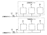
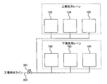
- FIG. 12 is a schematic diagram showing the arrangement of cleaning units and drying units arranged in a conventional substrate processing apparatus. As shown in FIG. 12, this substrate processing apparatus is provided with two cleaning lanes, that is, an upper cleaning lane and a lower cleaning lane. In the upper cleaning lane, the wafer is transferred in the order of the upper cleaning unit 152, the upper cleaning unit 154, and the upper drying unit 156, and in the lower cleaning lane, the lower cleaning unit 160, the lower cleaning unit 162, and the lower drying unit 164 are transferred. The wafers are transferred in the order of. In the upper cleaning lane and the lower cleaning lane, two wafers are cleaned and dried in parallel.
- a cleaning member made of a brush, sponge, or the like is rubbed against the wafer while supplying a chemical solution to the front and back surfaces of the wafer.
- the wafer is cleaned, and then the wafer is rinsed with pure water.
- IPA vapor mixture of isopropyl alcohol and N 2 gas
- pure water is supplied to the cleaning units 152, 154, 160, 162 and the drying units 156, 164 for wafer processing. Therefore, as shown in FIG. 12, the cleaning units 152, 154, 160, 162 and the drying units 156, 164 are connected to pure water supply pipes 300 extending from a factory pure water line, which is one of factory utilities. Is done.
- a pure water source valve 301 is disposed in the pure water supply pipe 300.
- Bacteria may be generated in the washing units 152, 154, 160, 162 and the drying units 156, 164.
- the generated bacteria and their dead bodies are carried on the wafer together with pure water, causing the wafer to be contaminated. Therefore, when bacteria are generated, hydrogen peroxide water is injected into the pure water supply pipe 300 to kill the bacteria, and then the pure water is caused to flow through the pure water supply pipe 300 to obtain the pure water supply pipe 300.
- the inside of the container is cleaned (flushing).
- the pure water is distributed from the single pure water supply pipe 300 to the cleaning units 152, 154, 160, 162 and the drying units 156, 164.
- the cleaning units 152, 154, 160, 162 and the drying units 156, 164 when bacteria are generated in any one of the units 152, 154, 156, 160, 162, 164, it is necessary to introduce hydrogen peroxide water into all the pure water supply pipes 300.
- both the upper cleaning lane and the lower cleaning lane cannot be used for wafer cleaning. It may take several hours to complete the cleaning using the hydrogen peroxide solution, and there is a problem that the down time for stopping the processing of the wafer becomes long.
- an object of the present invention is to provide a substrate processing apparatus that can continue processing a substrate even if bacteria are generated in any of a plurality of cleaning units. It is another object of the present invention to provide a pipe cleaning method for such a substrate processing apparatus.
- a first cleaning lane including a plurality of first cleaning units that supply pure water to a substrate and clean the substrate, and supply pure water to the substrate.
- a second cleaning lane including a plurality of second cleaning units for cleaning the substrate; a first pure water supply pipe for supplying the pure water to the first cleaning lane; and supplying the pure water to the second cleaning lane And a second pure water supply pipe.
- the first pure water supply pipe and the second pure water supply pipe are further provided with a first introduction port and a second introduction port for introducing hydrogen peroxide water, respectively.
- the first cleaning unit includes a first pure water supply nozzle that supplies pure water to the substrate, and a first chemical solution supply nozzle that supplies a mixed solution of pure water and a chemical solution to the substrate.
- the pure water supply pipe has a first pure water supply line connected to the first pure water supply nozzle and a first pure water mixing line connected to the first chemical liquid supply nozzle.
- the first pure water mixing line extends to the first chemical liquid supply nozzle via a mixer for mixing the pure water and the chemical liquid.
- the second cleaning unit includes a second pure water supply nozzle for supplying pure water to the substrate, and a second chemical liquid supply nozzle for supplying a mixed liquid of pure water and chemical to the substrate
- the pure water supply pipe includes a second pure water supply line connected to the second pure water supply nozzle and a second pure water mixing line connected to the second chemical liquid supply nozzle.
- the second pure water mixing line extends to the second chemical liquid supply nozzle via a mixer for mixing the pure water and the chemical liquid.
- the first cleaning lane further includes a first drying unit that supplies the pure water to the substrate and then dries the substrate, and the second cleaning lane supplies the pure water to the substrate. And further including a second drying unit for drying the substrate.
- a first cleaning lane including a plurality of first cleaning units that supply pure water to a substrate and clean the substrate, and a plurality of cleaning water that supply pure water to the substrate and clean the substrate.
- a second cleaning lane including a second cleaning unit; a first pure water supply pipe for supplying the pure water to the first cleaning lane; and a second pure water supply pipe for supplying the pure water to the second cleaning lane.
- a substrate cleaning apparatus pipe cleaning method comprising: supplying hydrogen peroxide water into the first pure water supply pipe to fill the first pure water supply pipe with hydrogen peroxide water; The first pure water supply pipe filled with hydrogen water is allowed to stand for a predetermined time, and then pure water is supplied into the first pure water supply pipe to clean the first pure water supply pipe. The substrate is cleaned in the second cleaning lane while the pure water supply pipe is left for the predetermined time.
- the flow rate of the pure water when cleaning the first pure water supply pipe is higher than the flow rate of the pure water when cleaning the substrate.
- a preferred embodiment is characterized in that the concentration of hydrogen peroxide contained in the hydrogen peroxide solution is 5 to 6%.
- the predetermined time is 4 hours or more.
- the time for supplying pure water to the first pure water supply pipe and cleaning the inside of the first pure water supply pipe is one hour or more.
- pure water is supplied to the first pure water supply pipe to clean the inside of the first pure water supply pipe, and then hydrogen peroxide water is supplied to the second pure water supply pipe.
- first pure water supply pipe and a second pure water supply pipe are provided.
- the first pure water supply pipe and the second pure water supply pipe are connected to the first washing lane and the second washing lane, respectively, and supply pure water independently to the first washing lane and the second washing lane. . Therefore, when bacteria are generated in either the first cleaning lane or the second cleaning lane, the hydrogen peroxide solution may be supplied only to the pure water supply pipe of the cleaning lane where the bacteria are generated. As a result, the substrate processing can be continued in the cleaning lane in which no bacteria are generated.
- FIG. 3A is a plan view showing the cleaning unit.
- FIG. 3B is a side view showing the cleaning unit. It is a schematic diagram which shows an upper stage washing lane and a lower stage washing lane. It is a perspective view which shows a washing
- FIG. 1 is a view showing a substrate processing apparatus according to an embodiment of the present invention, which includes a polishing unit, a cleaning unit, and a drying unit.
- This substrate processing apparatus is an apparatus that can perform a series of steps of polishing, cleaning, and drying a wafer that is an example of a substrate.
- the substrate processing apparatus includes a substantially rectangular housing 2, and the inside of the housing 2 is divided into a load / unload unit 6, a polishing unit 1 and a cleaning unit 8 by partition walls 2a and 2b.
- the substrate processing apparatus has an operation control unit 10 that controls a wafer processing operation.
- the load / unload unit 6 includes a load port 12 on which a wafer cassette for stocking a large number of wafers W is placed.
- a traveling mechanism 14 is laid along the load port 12 in the load / unload unit 6, and a transfer robot (loader) 16 that can move along the arrangement direction of the wafer cassettes on the traveling mechanism 14. is set up.
- the transfer robot 16 can access the wafer cassette mounted on the load port 12 by moving on the traveling mechanism 14.
- the polishing unit 1 is a region where the wafer W is polished, and includes a first polishing unit 1A, a second polishing unit 1B, a third polishing unit 1C, and a fourth polishing unit 1D.
- the first polishing unit 1A polishes a first polishing table 22A to which a polishing pad 20 having a polishing surface is attached, and holds the wafer W and presses the wafer W against the polishing pad 20 on the first polishing table 22A.
- the second polishing unit 1B includes a second polishing table 22B to which the polishing pad 20 is attached, a second polishing head 24B, a second polishing liquid supply nozzle 26B, a second dressing unit 28B, and a second atomizer.
- the third polishing unit 1C includes a third polishing table 22C to which the polishing pad 20 is attached, a third polishing head 24C, a third polishing liquid supply nozzle 26C, and a third dressing unit 28C.
- the fourth polishing unit 1D includes a fourth polishing table 22D to which the polishing pad 20 is attached, a fourth polishing head 24D, a fourth polishing liquid supply nozzle 26D, and a fourth polishing liquid supply nozzle 26D.
- a dressing unit 28D and a fourth atomizer 30D are provided.
- the first linear transporter 40 is disposed adjacent to the first polishing unit 1A and the second polishing unit 1B.
- the first linear transporter 40 is a mechanism that transfers the wafer W between four transfer positions (first transfer position TP1, second transfer position TP2, third transfer position TP3, and fourth transfer position TP4).
- a second linear transporter 42 is disposed adjacent to the third polishing unit 1C and the fourth polishing unit 1D.
- the second linear transporter 42 is a mechanism for transferring the wafer W between three transfer positions (fifth transfer position TP5, sixth transfer position TP6, and seventh transfer position TP7).
- a lifter 44 for receiving the wafer W from the transfer robot 16 is disposed adjacent to the first transfer position TP1.
- the wafer W is transferred from the transfer robot 16 to the first linear transporter 40 via the lifter 44.
- a shutter (not shown) is provided on the partition 2 a, and when transferring the wafer W, the shutter is opened and the wafer W is transferred from the transfer robot 16 to the lifter 44. It is supposed to be.
- the wafer W is transferred to the lifter 44 by the transfer robot 16, further transferred from the lifter 44 to the first linear transporter 40, and transferred to the polishing units 1 ⁇ / b> A and 1 ⁇ / b> B by the first linear transporter 40.
- the polishing head 24A of the first polishing unit 1A moves between the upper position of the first polishing table 22A and the second transport position TP2 by the swing operation. Accordingly, the transfer of the wafer W to the polishing head 24A is performed at the second transfer position TP2.
- the polishing head 24B of the second polishing unit 1B moves between the upper position of the polishing table 22B and the third transfer position TP3, and the transfer of the wafer W to the polishing head 24B is performed at the third transfer position TP3.
- the polishing head 24C of the third polishing unit 1C moves between the upper position of the polishing table 22C and the sixth transfer position TP6, and the transfer of the wafer W to the polishing head 24C is performed at the sixth transfer position TP6.
- the polishing head 24D of the fourth polishing unit 1D moves between the upper position of the polishing table 22D and the seventh transfer position TP7, and the transfer of the wafer W to the polishing head 24D is performed at the seventh transfer position TP7.
- a swing transporter 46 is disposed between the first linear transporter 40, the second linear transporter 42, and the cleaning unit 8.
- the wafer W is transferred from the first linear transporter 40 to the second linear transporter 42 by the swing transporter 46. Further, the wafer W is transferred to the third polishing unit 1C and / or the fourth polishing unit 1D by the second linear transporter 42.
- a temporary placement table 48 for the wafer W installed in a frame (not shown) is arranged. As shown in FIG. 1, the temporary placement table 48 is disposed adjacent to the first linear transporter 40, and is positioned between the first linear transporter 40 and the cleaning unit 8. The swing transporter 46 transfers the wafer W between the fourth transfer position TP4, the fifth transfer position TP5, and the temporary placement table 48.
- the wafer W placed on the temporary placement table 48 is transferred to the cleaning unit 8 by the first transfer robot 50 of the cleaning unit 8.
- the cleaning unit 8 includes an upper cleaning lane including an upper cleaning unit 52, an upper cleaning unit 54, and an upper drying unit 56, and a lower cleaning lane including a lower cleaning unit 60, a lower cleaning 62, and a lower drying unit 64. And have. Detailed configurations of the upper and lower lanes will be described later.
- the cleaning units 52 and 60 and the cleaning units 54 and 62 the polished wafer W is cleaned with a cleaning solution (pure water and chemical solution).
- the drying units 56 and 64 the cleaned wafer W is dried.
- the first transfer robot 50 transfers the wafer W from the temporary placement table 48 to the upper cleaning unit 52 (or the lower cleaning unit 60), and further from the upper cleaning unit 52 (or the lower cleaning unit 60) to the upper cleaning unit 54 ( Or it operates to transport to the lower cleaning unit 62).
- a second transfer robot 58 is disposed between the cleaning units 54 and 62 and the drying units 56 and 64. The second transfer robot 58 operates to transfer the wafer W from the upper cleaning unit 54 (or the lower cleaning unit 62) to the upper drying unit 56 (or the lower drying unit 64).
- the dried wafer W is taken out from the upper drying unit 56 (or the lower drying unit 64) by the transfer robot 16 and returned to the wafer cassette. In this way, a series of processes including polishing, cleaning, and drying are performed on the wafer W.
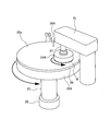
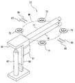
- FIG. 2 is a perspective view showing the first polishing unit 1A.
- the first polishing unit 1A supplies a polishing table 22A that supports the polishing pad 20, a polishing head 24A that presses the wafer W against the polishing pad 20, and a polishing liquid (slurry) to the polishing pad 20.
- a polishing liquid supply nozzle 26A In FIG. 2, the first dressing unit 28A and the first atomizer 30A are omitted.
- the polishing table 22A is connected to a table motor 25 disposed below the table shaft 23, and the table motor 25 rotates the polishing table 22A in the direction indicated by the arrow.
- the polishing pad 20 is affixed to the upper surface of the polishing table 22A, and the upper surface of the polishing pad 20 constitutes a polishing surface 20a for polishing the wafer W.
- the polishing head 24 ⁇ / b> A is fixed to the lower end of the polishing head shaft 27.
- the polishing head 24A is configured to hold the wafer W on the lower surface thereof by vacuum suction.
- the polishing head shaft 27 is connected to a rotation mechanism (not shown) installed in the polishing head arm 31, and the polishing head 24 ⁇ / b> A is rotationally driven via the polishing head shaft 27 by this rotation mechanism.
- the polishing of the surface of the wafer W is performed as follows.
- the polishing head 24A and the polishing table 22A are rotated in directions indicated by arrows, respectively, and a polishing liquid (slurry) is supplied onto the polishing pad 20 from the polishing liquid supply nozzle 26A.
- a polishing liquid slurry
- the wafer W is pressed against the polishing surface 20a of the polishing pad 20 by the polishing head 24A.
- the surface of the wafer W is polished by the mechanical action of abrasive grains contained in the polishing liquid and the chemical action of chemical components contained in the polishing liquid.
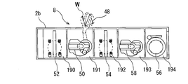
- FIG. 3A is a plan view showing the cleaning unit 8
- FIG. 3B is a side view showing the cleaning unit 8.
- the cleaning unit 8 is divided into a primary cleaning chamber 190, a first transfer chamber 191, a secondary cleaning chamber 192, a second transfer chamber 193, and a drying chamber 194. Yes.
- an upper cleaning unit 52 and a lower cleaning unit 60 are disposed in the primary cleaning chamber 190.
- the upper cleaning unit 52 is disposed above the lower cleaning unit 60.
- an upper cleaning unit 54 and a lower cleaning unit 62 are disposed in the secondary cleaning chamber 192.
- the upper cleaning unit 54 is disposed above the lower cleaning unit 62.
- the cleaning units 52, 54, 60, and 62 are cleaning machines that clean the wafer W using a cleaning liquid such as a chemical liquid and pure water. Since the cleaning units 52 and 60 and the cleaning units 54 and 62 are arranged along the vertical direction, there is an advantage that the footprint area is small.
- a temporary placement table 203 for the wafer W is provided between the upper cleaning unit 54 and the lower cleaning unit 62.
- An upper drying unit 56 and a lower drying unit 64 are disposed in the drying chamber 194.
- the upper drying unit 56 is disposed above the lower drying unit 64.
- Filter fan units 207 and 207 for supplying clean air into the drying units 56 and 64 are provided above the upper drying unit 56 and the lower drying unit 64, respectively.
- the upper cleaning unit 52, the lower cleaning unit 60, the upper cleaning unit 54, the lower cleaning unit 62, the temporary placing table 203, the upper drying unit 56, and the lower drying unit 64 are fixed to a frame (not shown) with bolts or the like. Has been.
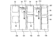
- the first transfer robot 50 is disposed in the first transfer chamber 191 and is configured to be movable up and down.
- a second transfer robot 58 is disposed in the second transfer chamber 193, and the second transfer robot 58 is configured to be movable up and down.
- the first transfer robot 50 and the second transfer robot 58 are movably supported by support shafts 211 and 212 extending in the vertical direction.
- the first transfer robot 50 and the second transfer robot 58 have a drive mechanism such as a motor inside thereof, and are movable up and down along the support shafts 211 and 212.
- the first transfer robot 50 has two upper and lower hands. As shown by the dotted line in FIG. 3A, the first transfer robot 50 is disposed at a position where the lower hand can access the temporary table 48 described above. When the lower hand of the first transfer robot 50 accesses the temporary placing table 48, a shutter (not shown) provided on the partition wall 2b is opened.
- the first transfer robot 50 operates to transfer the wafer W between the temporary table 48, the upper cleaning unit 52, the lower cleaning unit 60, the temporary table 203, the upper cleaning unit 54, and the lower cleaning unit 62. .
- the first transport robot 50 uses the lower hand and uses the upper hand when transporting the cleaned wafer W.
- the second transfer robot 58 operates to transfer the wafer W between the upper cleaning unit 54, the lower cleaning unit 62, the temporary placement table 203, the upper drying unit 56, and the lower drying unit 64. Since the second transfer robot 58 transfers only the cleaned wafer W, it has only one hand.
- the cleaning unit 8 includes an upper cleaning lane and a lower cleaning lane for cleaning a plurality of wafers W in parallel.
- the “cleaning lane” is a processing system composed of a plurality of cleaning units for cleaning the wafer W.
- the upper washing lane is one of the first washing lane and the second washing lane
- the lower washing lane is the other of the first washing lane and the second washing lane.
- the upper cleaning lane includes an upper cleaning unit 52, an upper cleaning unit 54, and an upper drying unit 56.
- the lower cleaning lane includes a lower cleaning unit 60, a lower cleaning unit 62, and a lower drying unit 64.
- one wafer W is transferred in the order of the first transfer robot 50, the upper cleaning unit 52, the first transfer robot 50, the upper cleaning unit 54, the second transfer robot 58, and the upper drying unit 56.
- the other wafers W are in the order of the first transfer robot 50, the lower cleaning unit 60, the first transfer robot 50, the lower cleaning unit 62, the second transfer robot 58, and the lower drying unit 64. Be transported. As described above, a plurality of (typically two) wafers W can be simultaneously cleaned and dried by two parallel cleaning lanes. Each cleaning lane includes two cleaning units, but may include three or more cleaning units.
- the cleaning units 52 and 60 and the cleaning units 54 and 62 are roll sponge type cleaning machines. Since the cleaning units 52 and 60 and the cleaning units 54 and 62 have the same configuration, the upper cleaning unit 52 will be described below.
- FIG. 5 is a perspective view showing the upper cleaning unit 52.
- the upper cleaning unit 52 includes four holding rollers (substrate holding units) 71, 72, 73, and 74 that hold and rotate the wafer W horizontally, and rolls that contact the upper and lower surfaces of the wafer W.
- Sponges (cleaning tools) 77, 78, rotating mechanisms 80, 81 for rotating the roll sponges 77, 78, upper pure water supply nozzles 85, 86 for supplying pure water to the upper surface of the wafer W, chemicals and pure Upper chemical solution supply nozzles 87 and 88 for supplying a water mixture to the upper surface of the wafer W are provided.
- a lower pure water supply nozzle for supplying pure water to the lower surface of the wafer W and a lower chemical liquid supply nozzle for supplying a mixed solution of chemical and pure water to the lower surface of the wafer W are also provided.
- the upper pure water supply nozzles 85 and 86, the lower pure water supply nozzle, the upper chemical liquid supply nozzles 87 and 88, and the lower chemical liquid supply nozzle are connected to a pure water supply pipe described later.
- the holding rollers 71, 72, 73, 74 can be moved in the direction of approaching and separating from the wafer W by a driving mechanism (for example, an air cylinder) (not shown).
- a rotating mechanism 80 that rotates the upper roll sponge 77 is attached to a guide rail 89 that guides its vertical movement.
- the rotating mechanism 80 is supported by an elevating drive mechanism 82, and the rotating mechanism 80 and the upper roll sponge 77 are moved up and down by the elevating drive mechanism 82.
- a rotation mechanism 81 for rotating the lower roll sponge 78 is also supported by the guide rail, and the rotation mechanism 81 and the lower roll sponge 78 are moved up and down by an elevating drive mechanism. .
- the lifting drive mechanism for example, a motor drive mechanism using a ball screw or an air cylinder is used.
- the roll sponges 77 and 78 move in directions close to each other and come into contact with the upper and lower surfaces of the wafer W.
- the wafer W is rotated around its axis.
- a mixed solution of chemical solution and pure water is supplied to the upper and lower surfaces of the wafer W from the upper chemical solution supply nozzles 87 and 88 and the lower chemical solution supply nozzle (not shown).
- the upper and lower surfaces of the wafer W are scrubbed by the roll sponges 77 and 78 slidably contacting the upper and lower surfaces of the wafer W while rotating around the horizontally extending axis.
- the wafer W is rinsed by supplying pure water from the upper pure water supply nozzles 85 and 86 and the lower pure water supply nozzle to the rotating wafer W.
- the rinsing of the wafer W may be performed while the roll sponges 77 and 78 are in sliding contact with the upper and lower surfaces of the wafer W, or may be performed with the roll sponges 77 and 78 being separated from the upper and lower surfaces of the wafer W.
- the cleaning units 52 and 60 and / or the cleaning units 54 and 62 may be a pen sponge type cleaning machine as shown in FIG.
- a roll sponge type washing machine may be used as the washing units 52 and 60
- a pen sponge type washing machine may be used as the washing units 54 and 62.
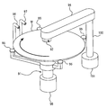
- FIG. 6 is a perspective view showing a pen sponge type washing machine.
- this type of cleaning machine includes a substrate holder 91 that holds and rotates the wafer W, a pen sponge 92, an arm 94 that holds the pen sponge 92, and pure water on the upper surface of the wafer W. And a chemical liquid supply nozzle 97 for supplying a mixed liquid of chemical liquid and pure water to the upper surface of the wafer W.
- the pen sponge 92 is connected to a rotation mechanism (not shown) disposed in the arm 94, and the pen sponge 92 is rotated about a central axis extending in the vertical direction.
- the pure water supply nozzle 96 and the chemical solution supply nozzle 97 are connected to a pure water supply pipe which will be described later.
- the substrate holding unit 91 includes a plurality of (four in FIG. 6) chucks 95 that hold the peripheral edge of the wafer W, and these wafers 95 hold the wafer W horizontally.
- a motor 98 is connected to the chuck 95, and the wafer W held by the chuck 95 is rotated around its axis by the motor 98.
- the arm 94 is disposed above the wafer W.
- a pen sponge 92 is connected to one end of the arm 94, and the pivot shaft 100 is connected to the other end of the arm 94.
- a motor 101 as an arm rotation mechanism for turning the arm 94 is connected to the turning shaft 100.
- the arm rotation mechanism may include a reduction gear in addition to the motor 101.
- the motor 101 turns the arm 94 in a plane parallel to the wafer W by rotating the turning shaft 100 by a predetermined angle. As the arm 94 turns, the pen sponge 92 supported by the arm 94 moves in the radial direction of the wafer W.
- the wafer W in the pen sponge type cleaning machine is cleaned as follows. First, the wafer W is rotated around its axis. Next, a mixed solution of chemical solution and pure water is supplied from the chemical solution supply nozzle 97 to the upper surface of the wafer W. In this state, the pen sponge 92 is slidably contacted with the upper surface of the wafer W while rotating around its vertically extending axis, and further swings along the radial direction of the wafer W. The pen sponge 92 is brought into sliding contact with the upper surface of the wafer W in the presence of the chemical solution, so that the wafer W is scrubbed.
- pure water is supplied from the pure water supply nozzle 96 to the upper surface of the rotating wafer W to rinse the wafer W in order to wash away the chemical from the wafer W.
- the rinsing of the wafer W may be performed while the pen sponge 92 is in sliding contact with the wafer W, or may be performed while the pen sponge 92 is separated from the wafer W.
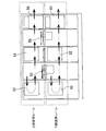
- FIG. 7 is a longitudinal sectional view showing the upper drying unit 56.
- the upper drying unit 56 includes a base 201 and four substrate support members 202 supported by the base 201.
- the base 201 is fixed to the upper end of the rotating shaft 206.
- the rotating shaft 206 is connected to a motor 215, and the base 201 is rotated about its axis by driving the motor 215.
- An upper pure water supply nozzle 254 that supplies pure water to the surface of the wafer W is disposed above the wafer W held on the base 201 via the substrate support member 202.
- the pure water supply nozzle 254 is arranged facing the center of the wafer W.
- the upper pure water supply nozzle 254 is connected to a pure water supply pipe to be described later, and pure water is supplied to the center of the surface of the wafer W through the upper pure water supply nozzle 254.
- two nozzles 260 and 261 for performing rotagony drying are arranged in parallel.
- the nozzle 260 is for supplying IPA vapor (a mixture of isopropyl alcohol and N 2 gas) to the surface of the wafer W.
- the nozzle 261 supplies pure water to prevent the surface of the wafer W from being dried, and is connected to a pure water supply pipe described later.
- These nozzles 260 and 261 are configured to be movable along the radial direction of the wafer W.
- a lower pure water supply nozzle (not shown) and a gas nozzle (not shown) are also arranged.
- the pure water supply pipe is connected to the lower pure water supply nozzle, and pure water is supplied to the back surface of the wafer W through the lower pure water supply nozzle.
- a dry gas supply line such as N 2 gas or dry air is connected to the gas nozzle, and the dry gas is supplied to the back surface of the wafer W through the gas nozzle.
- the wafer W is rotated by the motor 215.
- pure water is supplied from the upper pure water supply nozzle 254 and the lower pure water supply nozzle (not shown) to the front and back surfaces of the wafer W, and the entire surface of the wafer W is rinsed with pure water.
- the pure water supplied to the wafer W spreads over the entire front and back surfaces of the wafer W due to centrifugal force, whereby the entire wafer W is rinsed.
- the two nozzles 260 and 261 are in a predetermined standby position away from the wafer W.
- the supply of pure water from the pure water supply nozzle 254 is stopped, the pure water supply nozzle 254 is moved to a predetermined standby position away from the wafer W, and the two nozzles 260 and 261 are moved above the wafer W. Move to work position. Then, IPA vapor is supplied from the nozzle 260 and pure water is supplied from the nozzle 261 toward the surface of the wafer W while rotating the wafer W at a low speed of 30 to 150 min ⁇ 1 . At this time, pure water is also supplied to the back surface of the wafer W from the lower pure water supply nozzle. Then, the two nozzles 260 and 261 are simultaneously moved along the radial direction of the wafer W. Thereby, the surface of the wafer W is dried.
- the two nozzles 260 and 261 are moved to a predetermined standby position, and the supply of pure water from the lower pure water supply nozzle is stopped. Then, the wafer W is rotated at a high speed of 1000 to 1500 min ⁇ 1 and the pure water adhering to the back surface of the wafer W is shaken off. At this time, dry gas is sprayed from the gas nozzle to the back surface of the wafer W. In this way, the back surface of the wafer W is dried. The dried wafer W is taken out from the upper drying unit 56 by the transfer robot 16 shown in FIG. 1 and returned to the wafer cassette.
- FIG. 8 is a diagram illustrating an example of a pure water supply system that supplies pure water to the cleaning unit and the drying unit.
- the first pure water supply pipe 120 is connected to the upper cleaning lane having the upper cleaning units 52 and 54 and the upper drying unit 56, and the lower cleaning units 60 and 62 and the lower drying unit are connected.
- a second pure water supply pipe 180 is connected to the lower cleaning lane having 64.
- the 1st pure water supply piping 120 and the 2nd pure water supply piping 180 are each connected to the factory pure water line which is one of the utilities of a factory.
- Pure water used in the upper cleaning lane and pure water used in the lower cleaning lane are separately supplied from the first pure water supply pipe 120 and the second pure water supply pipe 180.
- the upper washing lane is one of the first washing lane and the second washing lane
- the lower washing lane is the other of the first washing lane and the second washing lane.
- a first pure water source valve 121 is disposed in the first pure water supply pipe 120.
- the first pure water source valve 121 is opened, pure water is supplied from the factory pure water line to the first pure water supply pipe 120, and when the first pure water source valve 121 is closed, the first pure water source valve is supplied from the factory pure water line. The supply of pure water to the supply pipe 120 is stopped.
- a second pure water source valve 181 is disposed in the second pure water supply pipe 180. When the second pure water source valve 181 is opened, pure water is supplied to the second pure water supply pipe 180 from the factory pure water line, and when the second pure water source valve 181 is closed, the second pure water is supplied from the factory pure water line. The supply of pure water to the supply pipe 180 is stopped.
- pure water supply to the upper cleaning lane and pure water supply to the lower cleaning lane are performed independently of each other. If a defect such as the generation of bacteria occurs in either one of the upper and lower lanes, the operation of the lane is stopped and sterilization and other repairs are performed. Even in this case, the other cleaning lane can continue to clean and dry the wafer. Therefore, the substrate processing apparatus can continue a series of processes including wafer polishing, cleaning, and drying.
- FIG. 9 is a diagram showing details of the pure water supply system shown in FIG.
- a first introduction port 130 for introducing hydrogen peroxide solution into the first pure water supply pipe 120 is attached on the secondary side of the first pure water source valve 121.
- An opening / closing valve 131 is attached to the first introduction port 130.
- This on-off valve 131 is basically closed except when hydrogen peroxide solution is introduced into the first pure water supply pipe 120.
- the first pure water supply pipe 120 is branched into a first pure water supply line 124 and a first pure water mixing line 125 at a branch point 122.
- the branch point 122 is located downstream of the first introduction port 130.
- the first pure water supply line 124 extends to the upper cleaning unit 52, the upper cleaning unit 54, and the upper drying unit 56, and is connected to the pure water supply nozzles 85, 86, 254, and 261 described above.
- the first pure water supply line 124 is connected to the pure water supply nozzle 96 shown in FIG.
- the first pure water supply line 124 constitutes a part of the first pure water supply pipe 120.
- a first pressure adjustment valve 123 is disposed in the first pure water supply line 124.
- the first pressure regulating valve 123 functions as a constant pressure valve that keeps the pure water pressure on the secondary side of the first pressure regulating valve 123 constant. Therefore, even if the primary side pure water pressure of the first pressure regulating valve 123 fluctuates, the pressure of pure water flowing to the upper cleaning unit 52, the upper cleaning unit 54, and the upper drying unit 56 is kept constant.
- the first pure water mixing line 125 constitutes a part of the first pure water supply pipe 120.
- the first pure water mixing line 125 is branched into a pure water mixing line 125A and a pure water mixing line 125B.
- the pure water mixing line 125 ⁇ / b> A is connected to the chemical solution supply nozzles 87 and 88 (see FIG. 5) of the upper cleaning unit 52 via the junction 231 and the mixer 232.
- the pure water mixing line 125 ⁇ / b> B is connected to the chemical solution supply nozzles 87 and 88 (see FIG. 5) of the upper cleaning unit 54 via the junction 234 and the mixer 235.
- the pure water mixing line 125A and the pure water mixing line 125B are connected to the chemical solution supply nozzle 97 shown in FIG.
- the chemical liquid is injected from the first chemical liquid inlet 230 into the first chemical liquid supply line 221.
- the first chemical liquid supply line 221 is branched into a chemical liquid supply line 221A and a chemical liquid supply line 221B.
- the chemical liquid supply line 221A is connected to the pure water mixing line 125A at a confluence 231 of the chemical liquid and pure water.
- the chemical liquid supply line 221B is connected to the pure water mixing line 125B at a confluence 234 of the chemical liquid and pure water.
- the chemical liquid flowing through the chemical liquid supply line 221A merges with pure water flowing through the pure water mixing line 125A at the confluence 231.
- the chemical solution and pure water further flow through the pure water mixing line 125 ⁇ / b> A to be introduced into the mixer 232, and are stirred and mixed by the mixer 232.
- the liquid mixture of the chemical liquid and pure water further flows through the pure water mixing line 125A and is supplied to the chemical liquid supply nozzles 87 and 88 (see FIG. 5) or the chemical liquid supply nozzle 97 (see FIG. 6) of the upper cleaning unit 52.
- the chemical liquid flowing through the chemical liquid supply line 221B merges with pure water flowing through the pure water mixing line 125B at the merge point 234.
- the chemical solution and pure water further flow through the pure water mixing line 125 ⁇ / b> B and are introduced into the mixer 235, and are stirred and mixed by the mixer 235.
- the liquid mixture of the chemical liquid and pure water further flows through the pure water mixing line 125B and is supplied to the chemical liquid supply nozzles 87 and 88 (see FIG. 5) or the chemical liquid supply nozzle 97 (see FIG. 6) of the upper cleaning unit 54.
- the second pure water supply pipe 180 has substantially the same configuration as the first pure water supply pipe 120.
- a second introduction port 200 for introducing the hydrogen peroxide solution into the second pure water supply pipe 180 is attached on the secondary side of the second pure water source valve 181.
- An opening / closing valve 201 is attached to the second introduction port 200. This on-off valve 201 is basically closed except when hydrogen peroxide solution is introduced into the second pure water supply pipe 180.
- the second pure water supply pipe 180 is branched into a second pure water supply line 184 and a second pure water mixing line 185 at a branch point 182.
- the branch point 182 is located on the downstream side of the second introduction port 200.
- the second pure water supply line 184 extends to the lower cleaning unit 60, the lower cleaning unit 62, and the lower drying unit 64, and is connected to the pure water supply nozzles 85, 86, 254, and 261 described above.
- the second pure water supply line 184 is connected to the pure water supply nozzle 96 shown in FIG.
- the second pure water supply line 184 constitutes a part of the second pure water supply pipe 180.
- a second pressure adjustment valve 183 is disposed in the second pure water supply line 184.
- the second pressure regulating valve 183 functions as a constant pressure valve that keeps the secondary pure water pressure of the second pressure regulating valve 183 constant. Therefore, even if the primary pure water pressure of the second pressure regulating valve 183 varies, the pressure of pure water flowing to the lower cleaning unit 60, the lower cleaning unit 62, and the lower drying unit 64 is kept constant. .
- the second pure water mixing line 185 constitutes a part of the second pure water supply pipe 180.
- the second pure water mixing line 185 is branched into a pure water mixing line 185A and a pure water mixing line 185B.
- the pure water mixing line 185A is connected to the chemical solution supply nozzles 87 and 88 (see FIG. 5) of the lower cleaning unit 60 via the junction 241 and the mixer 242.
- the pure water mixing line 185B is connected to the chemical solution supply nozzles 87 and 88 (see FIG. 5) of the lower cleaning unit 62 via the junction 244 and the mixer 245. 6 is used as the cleaning units 60 and 62, the pure water mixing line 185A and the pure water mixing line 185B are connected to the chemical solution supply nozzle 97 shown in FIG.
- the chemical solution is injected from the second chemical solution inlet 240 into the second chemical solution supply line 222.
- the second chemical liquid supply line 222 is branched into a chemical liquid supply line 222A and a chemical liquid supply line 222B.
- the chemical solution supply line 222A is connected to the pure water mixing line 185A at a confluence 241 of the chemical solution and pure water.
- the chemical solution supply line 222B is connected to the pure water mixing line 185B at the confluence 244 of the chemical solution and pure water.
- the chemical liquid flowing through the chemical liquid supply line 222A merges with pure water flowing through the pure water mixing line 185A at the confluence 241.
- the chemical solution and pure water further flow through the pure water mixing line 185A, are introduced into the mixer 242 and are stirred and mixed by the mixer 242.
- the liquid mixture of the chemical liquid and pure water further flows through the pure water mixing line 185A and is supplied to the chemical liquid supply nozzles 87 and 88 (see FIG. 5) or the chemical liquid supply nozzle 97 (see FIG. 6) of the lower cleaning unit 60. .
- the chemical liquid flowing through the chemical liquid supply line 222B joins with pure water flowing through the pure water mixing line 185B at the junction 244.
- the chemical solution and pure water further flow through the pure water mixing line 185B and are introduced into the mixer 245, and are stirred and mixed by the mixer 245.
- the liquid mixture of the chemical liquid and pure water further flows through the pure water mixing line 185B and is supplied to the chemical liquid supply nozzles 87 and 88 (see FIG. 5) or the chemical liquid supply nozzle 97 (see FIG. 6) of the lower cleaning unit 62. .
- the inspection using a microscope is periodically performed on the wafer W that has been subjected to a series of processes of polishing, cleaning, and drying in the substrate processing apparatus. If bacteria are generated in the pure water, the bacteria and their dead bodies can be found on the wafer W during this inspection.
- a processing history is stored as to which of the upper cleaning lane and the lower cleaning lane the wafer W to which bacteria are attached has passed. Therefore, it is possible to identify the cleaning lane used for cleaning the wafer W to which bacteria are attached.
- the washing lane where bacteria are generated needs to be washed with hydrogen peroxide.
- the pipe cleaning method of the substrate processing apparatus will be described using an example in which bacteria are found from the wafer W processed in the upper cleaning lane.
- Bacteria have been found from the wafer W processed in the upper cleaning lane, so the first pure water supply pipe 120 is cleaned. First, pure water is allowed to flow through the first pure water supply pipe 120 for about 10 minutes, and the pure water and the chemical solution in the first pure water supply pipe 120 are replaced with new pure water. As described above, the first pure water supply pipe 120 includes the first pure water supply line 124 and the first pure water mixing line 125. In particular, not only pure water but also a chemical solution exists in the first pure water mixing line 125. All the pure water and chemicals present in the first pure water supply pipe 120, the cleaning units 52 and 54, and the upper drying unit 56 are replaced with new pure water.
- the first pure water source valve 121 is closed, and the first pure water supply pipe 120 is disconnected from the factory pure water line.
- the factory hydrogen peroxide water line is connected to the first introduction port 130.
- a container in which hydrogen peroxide solution is stored may be prepared and connected to the first introduction port 130.
- the on-off valve 131 is opened, hydrogen peroxide water is supplied into the first pure water supply pipe 120 through the first introduction port 130 for about 15 minutes, and the pure water in the first pure water supply pipe 120 is supplied with hydrogen peroxide. Replace with water. Thereafter, the on-off valve 131 is closed to stop the supply of the hydrogen peroxide solution, and the first pure water supply pipe 120 is filled with the hydrogen peroxide solution.
- the first pure water supply pipe 120 In the state where the first pure water supply pipe 120 is filled with the hydrogen peroxide solution, the first pure water supply pipe 120 is left as it is for a predetermined time. After a predetermined time has elapsed, the first pure water source valve 121 is opened to supply pure water into the first pure water supply pipe 120, and the inside of the first pure water supply pipe 120 is washed with pure water.
- the pure water In order to surely replace the hydrogen peroxide solution in the first pure water supply pipe 120 with pure water, and in order to surely expel bacterial dead bodies from the first pure water supply pipe 120, the pure water is preferably Supply for 1 hour or more. Further, from the same point of view, the flow rate of pure water flowing through the first pure water supply pipe 120 when cleaning the first pure water supply pipe 120 is the pure water flowing through the first pure water supply pipe 120 when cleaning the wafer. It is preferable that the flow rate be higher.
- the concentration of hydrogen peroxide contained in the hydrogen peroxide solution used for cleaning the first pure water supply pipe 120 is 5 to 6%.
- the predetermined time for leaving the first pure water supply pipe 120 in a state filled with hydrogen peroxide is preferably 4 hours or longer. Bacteria are known to die only by being immersed in hydrogen peroxide solution of about 2% for a few seconds. Therefore, if bacteria are brought into contact with 5 to 6% hydrogen peroxide water for 4 hours or more, the bacteria in the first pure water supply pipe 120 can be surely killed.
- the wafer W can be cleaned and dried in the lower cleaning lane.
- the second pure water supply pipe 180 is cleaned by the same method, and the wafer W can be cleaned and dried in the upper cleaning lane.
- the first pure water supply pipe 120 and the second pure water supply pipe 180 are connected to the upper cleaning lane and the lower cleaning lane, respectively, and pure water is supplied to the units 52, 54, 56, 60, 62, 64. Supply. Therefore, when bacteria are generated in either the upper cleaning lane or the lower cleaning lane, hydrogen peroxide water may be introduced only into the pure water supply pipe of the cleaning lane where the bacteria are generated. As a result, the processing of the wafer W can be continued in the cleaning lane in which no bacteria are generated.
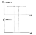
- FIG. 12 is a graph showing the flow rates in the upper and lower cleaning lanes.
- FIG. 11 is a graph showing the flow rates of the upper cleaning lane and the lower cleaning lane in the pure water supply system of the above-described embodiment.
- the flow rate of pure water is not affected by the use of pure water in the other cleaning lane. Therefore, the cleaning units 52, 54, 60 and 62 and the drying units 56 and 64 can supply pure water with a uniform flow rate to the wafer during the cleaning of the wafer.
- the present invention can be used for a substrate processing apparatus for processing a substrate by supplying a cleaning liquid (for example, pure water or a chemical solution) to a substrate such as a wafer, and a pipe cleaning method for the substrate processing apparatus.
- a cleaning liquid for example, pure water or a chemical solution
- Polishing unit 8 Cleaning unit 52 Upper cleaning unit 54 Upper cleaning unit 56 Upper drying unit 60 Lower cleaning unit 62 Lower cleaning unit 64 Lower drying unit 120 First pure water supply pipe 121 First pure water source valve 122 Branch point 123 First pressure adjustment valve 124 First pure water supply line 125 First pure water mixing line 130 First introduction port 131 On-off valve 180 Second pure water supply pipe 181 Second pure water source valve 182 Branch point 183 Second pressure adjustment Valve 184 Second pressure regulating pure water pipe 185 Second pure water mixing pipe 200 Second introduction port 201 On-off valve 221 First chemical liquid supply line 222 Second chemical liquid supply line 231 Junction point 232 Mixer 234 Junction point 235 Mixer 241 Junction Point 242 Mixer 244 Junction point 245 Mixer
Landscapes
- Engineering & Computer Science (AREA)
- Computer Hardware Design (AREA)
- Physics & Mathematics (AREA)
- Condensed Matter Physics & Semiconductors (AREA)
- General Physics & Mathematics (AREA)
- Manufacturing & Machinery (AREA)
- Microelectronics & Electronic Packaging (AREA)
- Power Engineering (AREA)
- Mechanical Engineering (AREA)
- Chemical & Material Sciences (AREA)
- Chemical Kinetics & Catalysis (AREA)
- General Chemical & Material Sciences (AREA)
- Cleaning Or Drying Semiconductors (AREA)
- Mechanical Treatment Of Semiconductor (AREA)
Priority Applications (5)
| Application Number | Priority Date | Filing Date | Title |
|---|---|---|---|
| US15/128,309 US10438818B2 (en) | 2014-03-27 | 2015-03-17 | Substrate processing apparatus and pipe cleaning method for substrate processing apparatus |
| CN201580016524.2A CN106165067B (zh) | 2014-03-27 | 2015-03-17 | 基板处理装置以及基板处理装置的配管清洗方法 |
| KR1020217019410A KR20210080609A (ko) | 2014-03-27 | 2015-03-17 | 기판 처리 장치 |
| SG11201607632YA SG11201607632YA (en) | 2014-03-27 | 2015-03-17 | Substrate processing apparatus and pipe cleaning method for substrate processing apparatus |
| KR1020167029052A KR102282729B1 (ko) | 2014-03-27 | 2015-03-17 | 기판 처리 장치의 배관 세정 방법 |
Applications Claiming Priority (2)
| Application Number | Priority Date | Filing Date | Title |
|---|---|---|---|
| JP2014-066998 | 2014-03-27 | ||
| JP2014066998A JP6159282B2 (ja) | 2014-03-27 | 2014-03-27 | 基板処理装置、および基板処理装置の配管洗浄方法 |
Publications (1)
| Publication Number | Publication Date |
|---|---|
| WO2015146724A1 true WO2015146724A1 (ja) | 2015-10-01 |
Family
ID=54195246
Family Applications (1)
| Application Number | Title | Priority Date | Filing Date |
|---|---|---|---|
| PCT/JP2015/057938 WO2015146724A1 (ja) | 2014-03-27 | 2015-03-17 | 基板処理装置、および基板処理装置の配管洗浄方法 |
Country Status (7)
Families Citing this family (5)
| Publication number | Priority date | Publication date | Assignee | Title |
|---|---|---|---|---|
| KR101776016B1 (ko) | 2015-10-21 | 2017-09-07 | 세메스 주식회사 | 배관 세정 방법 및 기판 처리 장치 |
| JP2017177303A (ja) * | 2016-03-31 | 2017-10-05 | 株式会社荏原製作所 | 基板研磨装置、その洗浄方法および基板研磨装置への液体供給装置 |
| KR102452928B1 (ko) * | 2016-12-16 | 2022-10-11 | 가부시키가이샤 에바라 세이사꾸쇼 | 세정 약액 공급 장치 및 세정 유닛 |
| US12220732B2 (en) | 2019-12-11 | 2025-02-11 | Ebara Corporation | Substrate cleaning system and substrate cleaning method |
| JP7355255B2 (ja) * | 2020-10-23 | 2023-10-03 | 株式会社Sumco | 枚葉式ウェーハ洗浄装置の配管の洗浄方法 |
Citations (4)
| Publication number | Priority date | Publication date | Assignee | Title |
|---|---|---|---|---|
| JPH1099855A (ja) * | 1996-08-05 | 1998-04-21 | Sony Corp | 限外濾過機能を備える超純水供給プラント、および超純水の供給方法 |
| JPH10505537A (ja) * | 1994-08-03 | 1998-06-02 | イールドアップ インターナショナル コーポレイション | 半導体製造時に粒子数を超低カウント数とする方法および装置 |
| JP2008246319A (ja) * | 2007-03-29 | 2008-10-16 | Dainippon Screen Mfg Co Ltd | 基板処理装置および基板処理方法 |
| JP2010050436A (ja) * | 2008-07-24 | 2010-03-04 | Ebara Corp | 基板処理装置および基板処理方法 |
Family Cites Families (13)
| Publication number | Priority date | Publication date | Assignee | Title |
|---|---|---|---|---|
| US4537640A (en) * | 1977-08-30 | 1985-08-27 | Schering Aktiengesellschaft | Rinsing of articles to remove an adhering substance |
| JPS6369588A (ja) | 1986-09-09 | 1988-03-29 | Mitsubishi Electric Corp | 半導体洗浄槽への純水供給システム |
| JPH0647105B2 (ja) * | 1989-12-19 | 1994-06-22 | 株式会社荏原総合研究所 | 純水又は超純水の精製方法及び装置 |
| JPH04139822A (ja) | 1990-10-01 | 1992-05-13 | Nec Corp | 半導体装置の洗浄装置 |
| JP2533460Y2 (ja) * | 1991-12-13 | 1997-04-23 | 大日本スクリーン製造株式会社 | 基板洗浄装置 |
| JP3433215B2 (ja) | 1993-03-29 | 2003-08-04 | 芝浦メカトロニクス株式会社 | 洗浄装置 |
| JP5511190B2 (ja) * | 2008-01-23 | 2014-06-04 | 株式会社荏原製作所 | 基板処理装置の運転方法 |
| CN103839857B (zh) * | 2008-06-04 | 2017-09-19 | 株式会社荏原制作所 | 基板处理装置及方法、基板把持机构以及基板把持方法 |
| JP5422143B2 (ja) * | 2008-06-04 | 2014-02-19 | 株式会社荏原製作所 | 基板把持機構 |
| US8795032B2 (en) | 2008-06-04 | 2014-08-05 | Ebara Corporation | Substrate processing apparatus, substrate processing method, substrate holding mechanism, and substrate holding method |
| CA2746773A1 (en) * | 2011-07-18 | 2013-01-18 | Fiber Connections Inc. | Field terminated fiber optic and electrical connection device |
| JP6212253B2 (ja) * | 2012-11-15 | 2017-10-11 | 株式会社荏原製作所 | 基板洗浄装置及び基板洗浄方法 |
| JP6104836B2 (ja) * | 2014-03-13 | 2017-03-29 | 東京エレクトロン株式会社 | 分離再生装置および基板処理装置 |
-
2014
- 2014-03-27 JP JP2014066998A patent/JP6159282B2/ja active Active
-
2015
- 2015-03-17 US US15/128,309 patent/US10438818B2/en active Active
- 2015-03-17 WO PCT/JP2015/057938 patent/WO2015146724A1/ja active Application Filing
- 2015-03-17 KR KR1020167029052A patent/KR102282729B1/ko active Active
- 2015-03-17 SG SG11201607632YA patent/SG11201607632YA/en unknown
- 2015-03-17 KR KR1020217019410A patent/KR20210080609A/ko not_active Ceased
- 2015-03-17 CN CN201580016524.2A patent/CN106165067B/zh active Active
- 2015-03-25 TW TW104109519A patent/TWI649780B/zh active
Patent Citations (4)
| Publication number | Priority date | Publication date | Assignee | Title |
|---|---|---|---|---|
| JPH10505537A (ja) * | 1994-08-03 | 1998-06-02 | イールドアップ インターナショナル コーポレイション | 半導体製造時に粒子数を超低カウント数とする方法および装置 |
| JPH1099855A (ja) * | 1996-08-05 | 1998-04-21 | Sony Corp | 限外濾過機能を備える超純水供給プラント、および超純水の供給方法 |
| JP2008246319A (ja) * | 2007-03-29 | 2008-10-16 | Dainippon Screen Mfg Co Ltd | 基板処理装置および基板処理方法 |
| JP2010050436A (ja) * | 2008-07-24 | 2010-03-04 | Ebara Corp | 基板処理装置および基板処理方法 |
Also Published As
| Publication number | Publication date |
|---|---|
| US10438818B2 (en) | 2019-10-08 |
| JP2015191972A (ja) | 2015-11-02 |
| KR20210080609A (ko) | 2021-06-30 |
| US20170117165A1 (en) | 2017-04-27 |
| CN106165067A (zh) | 2016-11-23 |
| CN106165067B (zh) | 2019-12-13 |
| KR102282729B1 (ko) | 2021-07-29 |
| SG11201607632YA (en) | 2016-10-28 |
| KR20160138145A (ko) | 2016-12-02 |
| TW201543540A (zh) | 2015-11-16 |
| TWI649780B (zh) | 2019-02-01 |
| JP6159282B2 (ja) | 2017-07-05 |
Similar Documents
| Publication | Publication Date | Title |
|---|---|---|
| CN108789132B (zh) | 基板清洗方法 | |
| JP6054805B2 (ja) | 基板洗浄装置 | |
| WO2015133516A1 (ja) | 基板処理システムおよび基板処理方法 | |
| JP2014167996A (ja) | 研磨装置および研磨方法 | |
| TW201811454A (zh) | 基板處理裝置 | |
| JP6159282B2 (ja) | 基板処理装置、および基板処理装置の配管洗浄方法 | |
| TWI681449B (zh) | 研磨方法及研磨裝置 | |
| JP6502430B2 (ja) | 基板処理装置 | |
| JP6378890B2 (ja) | 基板処理方法 | |
| JP7491774B2 (ja) | 基板保持回転機構、基板処理装置 | |
| JP2014203906A (ja) | 基板処理方法 | |
| JP2016043471A (ja) | 基板処理装置 | |
| KR20160042786A (ko) | 버프 처리 장치 및 기판 처리 장치 | |
| JP2017108113A (ja) | 基板処理装置および基板処理方法ならびに基板処理装置の制御プログラム | |
| KR101884640B1 (ko) | 화학 기계적 연마 시스템 | |
| JP2016111265A (ja) | バフ処理装置、および、基板処理装置 | |
| JP6625461B2 (ja) | 研磨装置 | |
| JP2010080840A (ja) | 回転式処理装置、処理システム及び回転式処理方法 | |
| JP6346541B2 (ja) | バフ処理装置、および、基板処理装置 | |
| US20240286245A1 (en) | Substrate treatment apparatus and method for treating substrate | |
| JP6091976B2 (ja) | 液体供給装置、及び基板処理装置 | |
| KR20250129014A (ko) | 기판 처리 장치 및 기판 처리 방법 | |
| JP2016043472A (ja) | 基板処理装置 |
Legal Events
| Date | Code | Title | Description |
|---|---|---|---|
| 121 | Ep: the epo has been informed by wipo that ep was designated in this application |
Ref document number: 15768961 Country of ref document: EP Kind code of ref document: A1 |
|
| WWE | Wipo information: entry into national phase |
Ref document number: 15128309 Country of ref document: US |
|
| NENP | Non-entry into the national phase |
Ref country code: DE |
|
| ENP | Entry into the national phase |
Ref document number: 20167029052 Country of ref document: KR Kind code of ref document: A |
|
| 122 | Ep: pct application non-entry in european phase |
Ref document number: 15768961 Country of ref document: EP Kind code of ref document: A1 |