WO2015145288A1 - リチウムイオン二次電池 - Google Patents
リチウムイオン二次電池 Download PDFInfo
- Publication number
- WO2015145288A1 WO2015145288A1 PCT/IB2015/051793 IB2015051793W WO2015145288A1 WO 2015145288 A1 WO2015145288 A1 WO 2015145288A1 IB 2015051793 W IB2015051793 W IB 2015051793W WO 2015145288 A1 WO2015145288 A1 WO 2015145288A1
- Authority
- WO
- WIPO (PCT)
- Prior art keywords
- negative electrode
- secondary battery
- lithium
- separator
- current collector
- Prior art date
- Legal status (The legal status is an assumption and is not a legal conclusion. Google has not performed a legal analysis and makes no representation as to the accuracy of the status listed.)
- Ceased
Links
Images






Classifications
-
- H—ELECTRICITY
- H01—ELECTRIC ELEMENTS
- H01M—PROCESSES OR MEANS, e.g. BATTERIES, FOR THE DIRECT CONVERSION OF CHEMICAL ENERGY INTO ELECTRICAL ENERGY
- H01M4/00—Electrodes
- H01M4/02—Electrodes composed of, or comprising, active material
- H01M4/04—Processes of manufacture in general
- H01M4/0438—Processes of manufacture in general by electrochemical processing
- H01M4/044—Activating, forming or electrochemical attack of the supporting material
- H01M4/0445—Forming after manufacture of the electrode, e.g. first charge, cycling
-
- H—ELECTRICITY
- H01—ELECTRIC ELEMENTS
- H01M—PROCESSES OR MEANS, e.g. BATTERIES, FOR THE DIRECT CONVERSION OF CHEMICAL ENERGY INTO ELECTRICAL ENERGY
- H01M4/00—Electrodes
- H01M4/02—Electrodes composed of, or comprising, active material
- H01M4/64—Carriers or collectors
-
- H—ELECTRICITY
- H01—ELECTRIC ELEMENTS
- H01M—PROCESSES OR MEANS, e.g. BATTERIES, FOR THE DIRECT CONVERSION OF CHEMICAL ENERGY INTO ELECTRICAL ENERGY
- H01M10/00—Secondary cells; Manufacture thereof
- H01M10/05—Accumulators with non-aqueous electrolyte
- H01M10/052—Li-accumulators
-
- H—ELECTRICITY
- H01—ELECTRIC ELEMENTS
- H01M—PROCESSES OR MEANS, e.g. BATTERIES, FOR THE DIRECT CONVERSION OF CHEMICAL ENERGY INTO ELECTRICAL ENERGY
- H01M10/00—Secondary cells; Manufacture thereof
- H01M10/05—Accumulators with non-aqueous electrolyte
- H01M10/052—Li-accumulators
- H01M10/0525—Rocking-chair batteries, i.e. batteries with lithium insertion or intercalation in both electrodes; Lithium-ion batteries
-
- H—ELECTRICITY
- H01—ELECTRIC ELEMENTS
- H01M—PROCESSES OR MEANS, e.g. BATTERIES, FOR THE DIRECT CONVERSION OF CHEMICAL ENERGY INTO ELECTRICAL ENERGY
- H01M10/00—Secondary cells; Manufacture thereof
- H01M10/05—Accumulators with non-aqueous electrolyte
- H01M10/056—Accumulators with non-aqueous electrolyte characterised by the materials used as electrolytes, e.g. mixed inorganic/organic electrolytes
-
- H—ELECTRICITY
- H01—ELECTRIC ELEMENTS
- H01M—PROCESSES OR MEANS, e.g. BATTERIES, FOR THE DIRECT CONVERSION OF CHEMICAL ENERGY INTO ELECTRICAL ENERGY
- H01M10/00—Secondary cells; Manufacture thereof
- H01M10/05—Accumulators with non-aqueous electrolyte
- H01M10/056—Accumulators with non-aqueous electrolyte characterised by the materials used as electrolytes, e.g. mixed inorganic/organic electrolytes
- H01M10/0564—Accumulators with non-aqueous electrolyte characterised by the materials used as electrolytes, e.g. mixed inorganic/organic electrolytes the electrolyte being constituted of organic materials only
- H01M10/0566—Liquid materials
- H01M10/0567—Liquid materials characterised by the additives
-
- H—ELECTRICITY
- H01—ELECTRIC ELEMENTS
- H01M—PROCESSES OR MEANS, e.g. BATTERIES, FOR THE DIRECT CONVERSION OF CHEMICAL ENERGY INTO ELECTRICAL ENERGY
- H01M10/00—Secondary cells; Manufacture thereof
- H01M10/05—Accumulators with non-aqueous electrolyte
- H01M10/056—Accumulators with non-aqueous electrolyte characterised by the materials used as electrolytes, e.g. mixed inorganic/organic electrolytes
- H01M10/0564—Accumulators with non-aqueous electrolyte characterised by the materials used as electrolytes, e.g. mixed inorganic/organic electrolytes the electrolyte being constituted of organic materials only
- H01M10/0566—Liquid materials
- H01M10/0568—Liquid materials characterised by the solutes
-
- H—ELECTRICITY
- H01—ELECTRIC ELEMENTS
- H01M—PROCESSES OR MEANS, e.g. BATTERIES, FOR THE DIRECT CONVERSION OF CHEMICAL ENERGY INTO ELECTRICAL ENERGY
- H01M10/00—Secondary cells; Manufacture thereof
- H01M10/05—Accumulators with non-aqueous electrolyte
- H01M10/056—Accumulators with non-aqueous electrolyte characterised by the materials used as electrolytes, e.g. mixed inorganic/organic electrolytes
- H01M10/0564—Accumulators with non-aqueous electrolyte characterised by the materials used as electrolytes, e.g. mixed inorganic/organic electrolytes the electrolyte being constituted of organic materials only
- H01M10/0566—Liquid materials
- H01M10/0569—Liquid materials characterised by the solvents
-
- H—ELECTRICITY
- H01—ELECTRIC ELEMENTS
- H01M—PROCESSES OR MEANS, e.g. BATTERIES, FOR THE DIRECT CONVERSION OF CHEMICAL ENERGY INTO ELECTRICAL ENERGY
- H01M4/00—Electrodes
- H01M4/02—Electrodes composed of, or comprising, active material
- H01M4/13—Electrodes for accumulators with non-aqueous electrolyte, e.g. for lithium-accumulators; Processes of manufacture thereof
-
- H—ELECTRICITY
- H01—ELECTRIC ELEMENTS
- H01M—PROCESSES OR MEANS, e.g. BATTERIES, FOR THE DIRECT CONVERSION OF CHEMICAL ENERGY INTO ELECTRICAL ENERGY
- H01M4/00—Electrodes
- H01M4/02—Electrodes composed of, or comprising, active material
- H01M4/36—Selection of substances as active materials, active masses, active liquids
- H01M4/58—Selection of substances as active materials, active masses, active liquids of inorganic compounds other than oxides or hydroxides, e.g. sulfides, selenides, tellurides, halogenides or LiCoFy; of polyanionic structures, e.g. phosphates, silicates or borates
- H01M4/582—Halogenides
-
- H—ELECTRICITY
- H01—ELECTRIC ELEMENTS
- H01M—PROCESSES OR MEANS, e.g. BATTERIES, FOR THE DIRECT CONVERSION OF CHEMICAL ENERGY INTO ELECTRICAL ENERGY
- H01M4/00—Electrodes
- H01M4/02—Electrodes composed of, or comprising, active material
- H01M4/64—Carriers or collectors
- H01M4/66—Selection of materials
- H01M4/661—Metal or alloys, e.g. alloy coatings
-
- H—ELECTRICITY
- H01—ELECTRIC ELEMENTS
- H01M—PROCESSES OR MEANS, e.g. BATTERIES, FOR THE DIRECT CONVERSION OF CHEMICAL ENERGY INTO ELECTRICAL ENERGY
- H01M50/00—Constructional details or processes of manufacture of the non-active parts of electrochemical cells other than fuel cells, e.g. hybrid cells
- H01M50/40—Separators; Membranes; Diaphragms; Spacing elements inside cells
-
- H—ELECTRICITY
- H01—ELECTRIC ELEMENTS
- H01M—PROCESSES OR MEANS, e.g. BATTERIES, FOR THE DIRECT CONVERSION OF CHEMICAL ENERGY INTO ELECTRICAL ENERGY
- H01M2220/00—Batteries for particular applications
- H01M2220/30—Batteries in portable systems, e.g. mobile phone, laptop
-
- H—ELECTRICITY
- H01—ELECTRIC ELEMENTS
- H01M—PROCESSES OR MEANS, e.g. BATTERIES, FOR THE DIRECT CONVERSION OF CHEMICAL ENERGY INTO ELECTRICAL ENERGY
- H01M50/00—Constructional details or processes of manufacture of the non-active parts of electrochemical cells other than fuel cells, e.g. hybrid cells
- H01M50/40—Separators; Membranes; Diaphragms; Spacing elements inside cells
- H01M50/489—Separators, membranes, diaphragms or spacing elements inside the cells, characterised by their physical properties, e.g. swelling degree, hydrophilicity or shut down properties
-
- Y—GENERAL TAGGING OF NEW TECHNOLOGICAL DEVELOPMENTS; GENERAL TAGGING OF CROSS-SECTIONAL TECHNOLOGIES SPANNING OVER SEVERAL SECTIONS OF THE IPC; TECHNICAL SUBJECTS COVERED BY FORMER USPC CROSS-REFERENCE ART COLLECTIONS [XRACs] AND DIGESTS
- Y02—TECHNOLOGIES OR APPLICATIONS FOR MITIGATION OR ADAPTATION AGAINST CLIMATE CHANGE
- Y02E—REDUCTION OF GREENHOUSE GAS [GHG] EMISSIONS, RELATED TO ENERGY GENERATION, TRANSMISSION OR DISTRIBUTION
- Y02E60/00—Enabling technologies; Technologies with a potential or indirect contribution to GHG emissions mitigation
- Y02E60/10—Energy storage using batteries
-
- Y—GENERAL TAGGING OF NEW TECHNOLOGICAL DEVELOPMENTS; GENERAL TAGGING OF CROSS-SECTIONAL TECHNOLOGIES SPANNING OVER SEVERAL SECTIONS OF THE IPC; TECHNICAL SUBJECTS COVERED BY FORMER USPC CROSS-REFERENCE ART COLLECTIONS [XRACs] AND DIGESTS
- Y02—TECHNOLOGIES OR APPLICATIONS FOR MITIGATION OR ADAPTATION AGAINST CLIMATE CHANGE
- Y02P—CLIMATE CHANGE MITIGATION TECHNOLOGIES IN THE PRODUCTION OR PROCESSING OF GOODS
- Y02P70/00—Climate change mitigation technologies in the production process for final industrial or consumer products
- Y02P70/50—Manufacturing or production processes characterised by the final manufactured product
Definitions
- One embodiment of the present invention relates to a lithium ion secondary battery and a method for manufacturing the same.
- one embodiment of the present invention is not limited to the above technical field.
- the technical field of one embodiment of the invention disclosed in this specification and the like relates to an object, a method, or a manufacturing method.
- one embodiment of the present invention relates to a process, a machine, a manufacture, or a composition (composition of matter). Therefore, as a technical field of one embodiment of the present invention disclosed more specifically in this specification, a semiconductor device, a display device, a light-emitting device, a power storage device, a memory device, a driving method thereof, or a manufacturing method thereof, Can be cited as an example.
- Examples of the secondary battery include a nickel metal hydride battery, a lead secondary battery, and a lithium ion secondary battery.
- These secondary batteries are used as power sources for portable information terminals typified by cellular phones.
- lithium ion secondary batteries have been actively developed because of their high capacity and miniaturization.
- Lithium ion secondary batteries are a wide range of lithium ion secondary batteries, which are made up of various processes such as electrode current collectors, electrode active materials, electrolytes, separators, and exterior body lead electrodes. In view of the application, it is important to be able to manufacture at a low cost. The smaller the member to be used, the number of steps required for manufacturing, and the time required for manufacturing, the lower the manufacturing cost.
- the negative electrode of a lithium ion secondary battery is generally produced by applying an active material made of a carbon material on a negative electrode current collector.
- An active material is a material that is involved in the insertion / extraction of ions (lithium ions), which are carriers, and the active material layer produced by coating the active material on the current collector includes A conductive auxiliary agent, a binder, etc. may be contained.
- Non-Patent Document 1 As a material suitable for the negative electrode, metallic lithium has preferable characteristics because of its low redox potential and high specific capacity per unit volume / weight.
- lithium in the electrolyte solution may be deposited in a dendrite shape (whisker shape) on the lithium metal during charging, which may cause a short circuit by breaking through the separator. ) Is eluted in the electrolyte solution, and isolated lithium is produced, resulting in a problem that cycle characteristics are deteriorated. Therefore, in a lithium ion secondary battery that has been put to practical use, an active material layer made of a carbon material is coated on a current collector to provide an active material layer, and the lithium ion storage / release reaction is used as a negative electrode reaction. (Non-Patent Document 1).
- the active material layer is produced, many facilities such as a kneading device for producing a slurry, a coater for applying the slurry, and a dryer for drying the slurry are required. Moreover, time is required for each process using these apparatuses. In addition, the cost of members such as active materials, conductive assistants, and binders is also high.
- the cell potential is lowered by the reaction potential of the active material in the secondary battery, and the energy density is reduced.
- the method of directly depositing lithium on the current collector can be adopted, the negative electrode has the lowest potential among all the systems inside the secondary battery, so the secondary battery with the highest energy density is produced. can do.
- One embodiment of the present invention includes a positive electrode, a negative electrode, an electrolytic solution, and a separator between the positive electrode and the negative electrode.
- the negative electrode includes a negative electrode current collector.
- the negative electrode current collector includes an electrolytic solution. Alternatively, it has a region in direct contact with at least one of the separators, the electrolytic solution has fluorine, and the negative electrode current collector is a lithium ion having a function of depositing lithium-containing precipitates on the surface during charging. It is a secondary battery.
- Another embodiment of the present invention includes a positive electrode, a negative electrode, an electrolytic solution, a separator between the positive electrode and the negative electrode, and a spacer between the separator and the negative electrode.
- the negative electrode current collector is in direct contact with the spacer, the electrolyte has fluorine, and precipitates having lithium can be deposited in a region between the separator and the negative electrode current collector. It is a lithium ion secondary battery having a function that can be performed.
- Another embodiment of the present invention includes a positive electrode, a negative electrode, an electrolytic solution, a separator between the positive electrode and the negative electrode, and a sheet-like spacer between the separator and the negative electrode.
- the spacer has a higher porosity than the separator
- the negative electrode has a negative electrode current collector
- the negative electrode current collector is in direct contact with the spacer
- the electrolyte has fluorine
- Another embodiment of the present invention includes a positive electrode, a negative electrode, an electrolytic solution, a separator between the positive electrode and the negative electrode, and a spacer between the separator and the negative electrode.
- the negative electrode current collector is in direct contact with the spacer, the electrolytic solution has fluorine, and the positive electrode, the negative electrode, the separator, and the spacer are flexible.
- the separator and the negative electrode current collector A lithium ion secondary battery having a function of depositing a lithium-containing precipitate in a region between the body and the body.
- fluorine is contained in an organic compound or an inorganic salt in the electrolytic solution.
- the organic compound or the inorganic salt is 2 wt% or more based on the weight of the electrolytic solution. It is good also as a lithium ion secondary battery which exists by weight.
- the organic compound may be a lithium ion secondary battery that is fluoroethylene carbonate.
- the inorganic salt may be a lithium ion secondary battery that is lithium tetrafluoroborate or lithium hexafluorophosphate.
- the negative electrode may be a lithium ion secondary battery that does not have an active material layer.
- the negative electrode current collector may be a lithium ion secondary battery having copper.
- the precipitate containing lithium may be a lithium ion secondary battery that is lithium fluoride.
- a spacer when a spacer is provided between the separator and the negative electrode current collector, a region where lithium can be deposited between the separator and the negative electrode current collector can be ensured.
- the region where lithium can be deposited by the spacer can be made larger.
- the volume occupied by the spacer is small.
- the porosity is high. If the spacer has a high porosity, the weight of the lithium ion secondary battery can be further reduced.
- the spacer does not need to support the structure of the lithium ion secondary battery, it is not necessary to use a spacer having a fixed shape, and a spacer having flexibility can be used.
- the flexible spacer can also be applied to a flexible lithium ion secondary battery, and the spacer can be deformed in accordance with the deformation of the lithium ion secondary battery.
- the negative electrode can be used in a lithium ion secondary battery without providing an active material layer
- the secondary battery can be manufactured while suppressing the equipment, time, and monetary costs associated with the process of forming the active material layer. Can be produced.
- a negative electrode can be manufactured without using an active material made of a carbon-based material.
- a lithium ion secondary battery can be provided without causing time and money costs associated with forming the negative electrode active material layer.
- dendritic (whisker-like) lithium that is deposited on the surface of the lithium metal in the negative electrode during charging can be reduced.
- a lithium ion secondary battery having good cycle characteristics can be provided.
- a secondary battery having a large capacity per unit mass and volume can be provided.
- a novel secondary battery, a novel power storage device, a novel secondary battery manufacturing method, or a novel power storage device manufacturing method can be provided.
- FIG. 6 illustrates a secondary battery according to one embodiment of the present invention.
- FIG. 6 shows results of XPS analysis of a negative electrode surface of a secondary battery according to one embodiment of the present invention.
- FIG. 6 shows an observation image of a negative electrode surface of a secondary battery according to one embodiment of the present invention by SEM.
- FIG. 6 shows cycle characteristics of the secondary battery according to one embodiment of the present invention.
- the figure explaining a curvature radius. 4A and 4B each illustrate an electronic device including a secondary battery according to one embodiment of the present invention.
- FIG. 4A and 4B each illustrate an electronic device including a secondary battery according to one embodiment of the present invention.
- the figure observed from the side of the electronic device which has the secondary battery which concerns on 1 aspect of this invention.
- FIG. 6 illustrates a secondary battery according to one embodiment of the present invention.
- each component such as the size and thickness of the positive electrode, the negative electrode, the active material layer, the separator, and the outer package is exaggerated for clarity of description. May have been. Therefore, each component is not necessarily limited to the size, and is not limited to the relative size between the components.
- FIG. 1B is a cross-sectional view of the lithium ion secondary battery 110.
- 3 is a schematic cross-sectional view of a state in which a positive electrode current collector 101a, a positive electrode active material layer 101b, a separator 104, and a negative electrode current collector 102 are stacked and sealed together with an electrolyte 105 together with an exterior body 106.
- the secondary battery may have a stacked structure.
- the positive electrode 101 includes a positive electrode current collector 101a and a positive electrode active material layer 101b, but the negative electrode does not have a negative electrode active material layer.
- the negative electrode current collector 102 is a main member constituting the negative electrode. In some cases, the negative electrode current collector 102 is in direct contact with the separator 104. In this case, the negative electrode current collector 102 is in direct contact with the electrolytic solution 105 present in the opening of the separator 104. On the other hand, when the separator 104 and the negative electrode current collector 102 do not contact, the electrolytic solution 105 contacts the negative electrode current collector 102 over the entire area of at least one surface of the negative electrode current collector 102.
- the negative electrode will be described.
- the negative electrode does not have an active material layer, and the negative electrode current collector 102 is a main member constituting the negative electrode.
- the negative electrode current collector 102 is made of a material that is highly conductive and does not alloy with carrier ions such as lithium, such as metals such as stainless steel, gold, platinum, zinc, iron, copper, aluminum, titanium, and tantalum, and alloys thereof. Can be used. Alternatively, an aluminum alloy to which an element that improves heat resistance, such as silicon, titanium, neodymium, scandium, or molybdenum, is added can be used. Alternatively, a metal element that forms silicide by reacting with silicon may be used.
- metal elements that react with silicon to form silicide include zirconium, titanium, hafnium, vanadium, niobium, tantalum, chromium, molybdenum, tungsten, cobalt, nickel, and the like.
- Metallic lithium has favorable properties due to its low oxidation-reduction potential and high specific capacity per unit volume / weight. However, due to the reactivity of metallic lithium in the atmosphere, handling with consideration for safety is required. It is a problem. Therefore, it is preferable not to use metallic lithium for the negative electrode current collector. Even if metallic lithium is deposited on the current collector by charging the secondary battery, the problem does not occur because the secondary battery is sealed.
- the negative electrode current collector 102 has at least a region that can be directly covered with the electrolytic solution 105 or the separator without being covered with the active material layer. Then, lithium precipitates in the region of the negative electrode current collector 102 by a reaction due to charging. However, as the charging proceeds, lithium in the electrolytic solution is deposited on the lithium in a dendrite shape (whisker shape). When charging further proceeds, dendritic (whisker-like) lithium grows and may break through the separator and cause a short circuit. In addition, the root of dendrites (whiskers) elutes in the electrolyte during discharge, producing isolated lithium, and the capacity is reduced by lithium lost in the electrolyte without undergoing a battery reaction, resulting in poor cycle characteristics. Problems arise.
- an active material layer made of, for example, a carbon material on the negative electrode current collector It is also possible to avoid this problem by providing an active material layer made of, for example, a carbon material on the negative electrode current collector.
- many facilities such as a kneading device for producing a slurry, a coater for applying the slurry, and a dryer for drying the slurry are required.
- time is required for each process using these apparatuses.
- the cost of members such as active materials, conductive assistants, and binders is also high.
- part of the manufacturing equipment for the secondary battery can be omitted, which can reduce the manufacturing cost. it can.
- the cell potential is lowered by the reaction potential of the active material in the secondary battery, and the energy density is reduced.
- the negative electrode since lithium is directly deposited on the current collector, the negative electrode has the lowest potential among all the systems inside the secondary battery. A secondary battery having a high density can be manufactured.
- the negative electrode of the lithium ion secondary battery can be manufactured.
- the positive electrode 101 will be described.
- the positive electrode 101 includes at least a positive electrode current collector 101a and a positive electrode active material layer 101b.
- the positive electrode active material a material that can insert and desorb carrier ions such as lithium ions can be used.
- the positive electrode active material has an olivine crystal structure, a layered rock salt crystal structure, or a spinel crystal structure. Examples include lithium-containing materials.
- olivine type lithium-containing materials (general formula LiMPO 4 (M is Fe (II), Mn (II), Co (II) or Ni (II))) include LiFePO 4 , LiNiPO 4 , LiCoPO 4 .
- LiMnPO 4 LiFe a Ni b PO 4, LiFe a Co b PO 4, LiFe a Mn b PO 4, LiNi a Co b PO 4, LiNi a Mn b PO 4 (a + b ⁇ 1, 0 ⁇ a ⁇ 1 , 0 ⁇ b ⁇ 1), LiFe c Ni d Co e PO 4, LiFe c Ni d Mn e PO 4, LiNi c Co d Mn e PO 4 (c + d + e ⁇ 1, 0 ⁇ c ⁇ 1,0 ⁇ d ⁇ 1,0 ⁇ e ⁇ 1), LiFe f Ni g Co h Mn i PO 4 (f + g + h + i is 1 or less, 0 ⁇ f ⁇ 1,0 ⁇ g ⁇ 1,0 ⁇ h ⁇ 1,0 ⁇ i 1), and the like.
- lithium iron phosphate (LiFePO 4 ) satisfies the requirements for the positive electrode active material in a well-balanced manner, such as safety, stability, high capacity density, high generation potential, and the presence of lithium extracted during initial oxidation (charging). Therefore, it is preferable.
- lithium-containing material having a layered rock salt type crystal structure examples include NiCo-based materials such as lithium cobaltate (LiCoO 2 ), LiNiO 2 , LiMnO 2 , Li 2 MnO 3 , and LiNi 0.8 Co 0.2 O 2 (
- the general formula is NiMn series such as LiNi x Co 1-x O 2 (0 ⁇ x ⁇ 1)), LiNi 0.5 Mn 0.5 O 2 (general formula is LiNi x Mn 1-x O 2 (0 ⁇ x ⁇ 1)), also referred to as NiMnCo system (NMC such LiNi 1/3 Mn 1/3 Co 1/3 O 2 .
- LiNi x Mn y Co 1- x-y O 2 (x> 0 , Y> 0, x + y ⁇ 1)).
- Li (Ni 0.8 Co 0.15 Al 0.05) O 2 Li 2 MnO 3 -LiMnO 2 (M is Co, Ni or Mn) may also be mentioned, and the like.
- LiCoO 2 has the capacity is large, it is stable in the atmosphere as compared to LiNiO 2, because there are advantages such that it is thermally stable than LiNiO 2, preferred.
- lithium-containing material having a spinel crystal structure examples include LiMn 2 O 4 , Li 11x Mn 2x O 4 , Li (MnAl) 2 O 4 , LiMn 1.5 Ni 0.5 O 4, and the like. .
- LiMn 2 O 4 a lithium-containing material having a spinel crystal structure containing manganese
- the positive electrode active material the general formula Li (2-j) MSiO 4 (M is Fe (II), Mn (II), Co (II), or Ni (II)) (j is 0 or more and 2 or less)
- the complex oxide represented by these can be used.
- Li (2-j) MSiO 4 include Li (2-j) FeSiO 4 , Li (2-j) NiSiO 4 , Li (2-j) CoSiO 4 , Li (2-j) MnSiO 4, Li (2-j) Fe k Ni l SiO 4, Li (2-j) Fe k Co l SiO 4, Li (2-j) Fe k Mn l SiO 4, Li (2-j) Ni k Co l SiO 4, Li (2- j) Ni k Mn l SiO 4 (k + l is 1 or less, 0 ⁇ k ⁇ 1,0 ⁇ l ⁇ 1), Li (2-j) Fe m Ni n Co q SiO 4, Li (2-j) Fe m Ni n Mn q SiO 4, Li (2-j) Ni m Co n Mn q SiO 4 (m + n + q is 1 or less, 0 ⁇ m ⁇ 1,0 ⁇ n ⁇ 1,0 ⁇ q ⁇ 1), Li (2-j) Fe m Ni
- a x M 2 (XO 4 ) 3 (A is Li, Na, or Mg) (M is Fe, Mn, Ti, V, Nb, or Al) (X is S, P , Mo, W, As, or Si), a NASICON compound represented by the general formula can be used.
- NASICON compounds include Fe 2 (MnO 4 ) 3 , Fe 2 (SO 4 ) 3 , and Li 3 Fe 2 (PO 4 ) 3 .
- a positive electrode active material a compound represented by a general formula of Li 2 MPO 4 F, Li 2 MP 2 O 7 , Li 5 MO 4 (M is Fe or Mn), a perovskite fluoride such as NaFeF 3 , TiS 2 , metal chalcogenides such as MoS 2 (sulfides, selenides, tellurides), lithium-containing material having a reverse spinel type crystal structure such as LiMVO 4 , vanadium oxides (V 2 O 5 , V 6 O 13 , LiV 3 O 8 and the like), manganese oxide-based materials, organic sulfur-based materials, and the like can be used.
- the carrier ions are alkali metal ions other than lithium ions, alkaline earth metal ions, beryllium ions, or magnesium ions
- an alkali metal for example, Sodium, potassium, etc.
- alkaline earth metals eg, calcium, strontium, barium, etc.
- beryllium or magnesium
- a sodium-containing layered oxide such as NaFeO 2 or Na 2/3 [Fe 1/2 Mn 1/2 ] O 2 can be used as the positive electrode active material.
- a material obtained by combining a plurality of the above materials may be used as the positive electrode active material.
- a solid solution obtained by combining a plurality of the above materials can be used as the positive electrode active material.
- a solid solution of LiCo 1/3 Mn 1/3 Ni 1/3 O 2 and Li 2 MnO 3 can be used as the positive electrode active material.
- the positive electrode active material a material having an average primary particle diameter of 50 nm or more and 100 ⁇ m or less is preferably used.
- acetylene black (AB), graphite (graphite) particles, carbon nanotubes, graphene, fullerene, or the like can be used as the conductive assistant for the electrode.
- the conductive assistant can form a network of electron conduction in the electrode.
- the conductive auxiliary agent can maintain the electric conduction path between the positive electrode active materials.
- PVDF polyvinylidene fluoride
- a binder polyimide, polytetrafluoroethylene, polyvinyl chloride, ethylene propylene diene polymer, styrene-butadiene rubber, acrylonitrile-butadiene rubber, fluorine rubber, polyvinyl acetate, poly Methyl methacrylate, polyethylene, nitrocellulose and the like can be used.
- the content of the binder with respect to the total amount of the positive electrode active material layer 101b is preferably 1 wt% or more and 10 wt% or less, more preferably 2 wt% or more and 8 wt% or less, and further preferably 3 wt% or more and 5 wt% or less.
- the content of the conductive additive with respect to the total amount of the positive electrode active material layer 101b is preferably 1 wt% or more and 10 wt% or less, and more preferably 1 wt% or more and 5 wt% or less.
- the positive electrode active material layer 101b is formed using a coating method, a positive electrode active material, a binder, a conductive additive, and a dispersion medium are mixed to prepare an electrode slurry, which is applied onto the positive electrode current collector 101a and dried. Just do it.
- a metal material containing aluminum as a main component is used as the positive electrode current collector 101a.
- the positive electrode current collector 101a can be formed using a material that has high conductivity and does not alloy with carrier ions such as lithium, such as metals such as stainless steel, gold, platinum, aluminum, and titanium, and alloys thereof.
- carrier ions such as lithium
- metals such as stainless steel, gold, platinum, aluminum, and titanium
- an aluminum alloy to which an element that improves heat resistance, such as silicon, titanium, neodymium, scandium, or molybdenum, is added can be used.
- a metal element that forms silicide by reacting with silicon may be used. Examples of metal elements that react with silicon to form silicide include zirconium, titanium, hafnium, vanadium, niobium, tantalum, chromium, molybdenum, tungsten, cobalt, nickel, and the like.
- a foil shape, a plate shape (sheet shape), a net shape, a punching metal shape, an expanded metal shape, or the like can be used as appropriate.
- a positive electrode of a lithium ion secondary battery can be manufactured.
- the separator 104 will be described.
- paper, non-woven fabric, glass fiber, or synthetic fiber such as nylon (polyamide), vinylon (polyvinyl alcohol fiber), polyester, acrylic, polyolefin, polyurethane, or the like may be used. However, it is necessary to select a material that does not dissolve in the electrolyte solution described later.
- a fluoropolymer for example, a fluoropolymer, a polyether such as polyethylene oxide and polypropylene oxide, a polyolefin such as polyethylene and polypropylene, polyacrylonitrile, polyvinylidene chloride, polymethyl methacrylate, polymethyl acrylate, One kind selected from polyvinyl alcohol, polymethacrylonitrile, polyvinyl acetate, polyvinyl pyrrolidone, polyethyleneimine, polybutadiene, polystyrene, polyisoprene, polyurethane polymer and derivatives thereof, cellulose, paper, nonwoven fabric, glass fiber alone, or Two or more types can be used in combination.
- a fluoropolymer for example, a fluoropolymer, a polyether such as polyethylene oxide and polypropylene oxide, a polyolefin such as polyethylene and polypropylene, polyacrylonitrile, polyvinylidene chloride, polymethyl methacrylate
- the separator 104 must have an insulating performance for preventing contact between both electrodes, a performance for holding an electrolytic solution, and an ionic conductivity.
- a method for producing a membrane having a function as a separator there is a method by stretching the membrane. For example, there is a stretch opening method in which a molten polymer material is developed to dissipate heat, and the obtained film is stretched in a biaxial direction parallel to the film to form holes.
- a secondary battery can be formed by housing a positive electrode, a negative electrode, and a separator in an exterior body and including an electrolyte solution.
- a secondary battery can be formed by housing the electrode wrapped in the separator and the other electrode together in an outer package and including an electrolytic solution.
- the separator 104 may have a plurality of layers.
- the separator 104 can be formed by the above-described method, but due to the mechanical strength of the constituent material and the film, the range of the pore size of the film and the thickness of the film are limited.
- the first separator and the second separator can be respectively produced by a stretching method, and these can be used together for a secondary battery.
- the material constituting the first separator and the second separator one or more kinds selected from the above materials or materials other than those described above can be used.
- the film Characteristics such as the size of the pores inside, the ratio of the volume occupied by the pores (also referred to as porosity), and the thickness of the film can be determined.
- the secondary battery may have flexibility. Even when deformation stress is applied to the flexible secondary battery, the stress can be relieved by sliding both separators at the interface between the first separator and the second separator.
- a structure using a separator is also suitable as a structure of a flexible secondary battery separator.
- the spacer will be described.
- a spacer can be provided between the negative electrode current collector and the separator.
- a spacer is provided between the separator and the negative electrode current collector, a region where lithium can be deposited can be ensured between the separator and the negative electrode current collector.
- lithium can be deposited on the surface of the negative electrode current collector without the spacer, the region where lithium can be deposited by the spacer can be made larger.
- lithium can be deposited in the voids in the separator without a spacer, but an accident in which lithium deposited in the separator short-circuits between the positive and negative electrodes can be prevented by using the spacer.
- FIG. 13 is a cross-sectional view of a lithium ion secondary battery according to one embodiment of the present invention in which a spacer 108 is provided between the separator 104 and the negative electrode current collector 106.
- the volume of the spacer in the space between the separator and the negative electrode current collector is small.
- the porosity is high, and it is preferable that it is higher than the porosity of the separator. If the spacer has a high porosity, not only can the area where lithium can be deposited be increased, but also the weight of the spacer can be reduced, so that it is not necessary to increase the weight of the lithium ion secondary battery. .
- the spacer does not necessarily support the structure of the lithium ion secondary battery, it is not necessary to use a fixed spacer having high rigidity, and a flexible spacer can be used.
- the flexible spacer can be applied to a flexible lithium ion secondary battery, and the spacer can be deformed in accordance with the deformation of the lithium ion secondary battery.
- the current collector is not destroyed and the spacer itself is not destroyed.
- a highly rigid spacer is not excluded.
- separator and the negative electrode current collector Even when a spacer is provided between the separator and the negative electrode current collector, it is not necessary to completely separate the separator and the negative electrode current collector, even if the separator and the negative electrode current collector are partially in contact with each other. Good. Of course, the separator and the negative electrode current collector need not be in direct contact. It is only necessary to secure a larger region where lithium can be deposited as compared with the case where no spacer is provided.
- the shape of the spacer may be spherical or columnar in addition to the above-described sheet shape. If it is a sheet-like spacer, it can be provided by being sandwiched between the separator and the negative electrode current collector, and if it is a spherical or columnar spacer, it can be dispersed on the separator or the negative electrode current collector. Alternatively, a spacer having a predetermined shape can be provided at a predetermined position by forming a film on the separator or the negative electrode current collector and patterning the film.
- paper, non-woven fabric, glass fiber, or synthetic fibers such as nylon (polyamide), vinylon (polyvinyl alcohol fiber), polyester, acrylic, polyolefin, polyurethane, etc. Can be used. Further, aramid can be used as a kind of nylon (polyamide). However, it is necessary to select a material that does not dissolve in the electrolyte solution described later.
- the electrolytic solution 105 will be described.
- the electrolyte refers to a liquid electrolyte that serves as a path for lithium ions responsible for charge transfer between the positive electrode and the negative electrode.
- aqueous electrolytes cannot be used because they are electrolyzed by lithium. Therefore, what dissolved the salt which has lithium in the organic solvent is used as electrolyte solution.
- the electrolyte solution 105 that can be used in the lithium ion secondary battery is preferably a non-aqueous solution (solvent) containing an electrolyte (solute).
- the solvent of the electrolytic solution 105 is preferably an aprotic organic solvent, such as ethylene carbonate (EC), propylene carbonate (PC), butylene carbonate, chloroethylene carbonate, vinylene carbonate, ⁇ -butyrolactone, ⁇ -valerolactone, dimethyl.
- aprotic organic solvent such as ethylene carbonate (EC), propylene carbonate (PC), butylene carbonate, chloroethylene carbonate, vinylene carbonate, ⁇ -butyrolactone, ⁇ -valerolactone, dimethyl.
- DMC Carbonate
- DEC diethyl carbonate
- EMC ethyl methyl carbonate
- DME dimethoxyethane
- DME dimethyl sulfoxide
- diethyl ether Methyl diglyme, acetonitrile, benzonitrile, tetrahydrofuran, sulfolane, sultone, etc., or two or more of these can be used in any combination and ratio.
- the lithium ion secondary battery can be reduced in thickness and weight.
- Typical examples of the polymer material to be gelated include silicone gel, acrylic gel, acrylonitrile gel, polyethylene oxide, polypropylene oxide, and fluorine-based polymer.
- one or more ionic liquids also referred to as room temperature molten salts
- room temperature molten salts that are flame retardant and hardly evaporable
- the lithium ion secondary battery can be prevented from bursting or igniting. Thereby, the safety
- an inorganic salt having fluorine for example, LiPF 6 , LiAsF 6 , LiBF 4 , LiCF 3 SO 3 , LiC 4 F 9 SO 3 , LiC (CF 3 SO 2 ) 3 , Lithium salts such as LiC (C 2 F 5 SO 2 ) 3 , LiN (CF 3 SO 2 ) 2 , LiN (C 4 F 9 SO 2 ) (CF 3 SO 2 ), LiN (C 2 F 5 SO 2 ) 2
- an electrolytic solution containing lithium tetrafluoroborate (LiBF 4 ) or lithium hexafluorophosphate (LiPF 6 ) is used as a secondary battery using a negative electrode current collector having a region where no active material is formed.
- a negative electrode current collector having a region where no active material is formed.
- the initial charge capacity is larger than when an inorganic salt having fluorine is not used for the electrolytic solution.
- fluorine By having fluorine in the electrolytic solution, fluorine can be provided to lithium deposited on the surface of the current collector, but an organic compound having fluorine may be added to the electrolytic solution as an additive. ) Can be suppressed, the generation of lithium that does not contribute to the battery reaction can be suppressed, the discharge capacity can be maintained, and as a result, the discharge capacity can be increased.
- Examples of the additive added to the electrolytic solution include fluorine-containing ethylene carbonate, such as fluoroethylene carbonate (4-fluoro-1,3-dioxolan-2-one, FEC).
- fluorine-containing ethylene carbonate such as fluoroethylene carbonate (4-fluoro-1,3-dioxolan-2-one, FEC).
- the carrier ions are lithium ions, but carrier ions other than lithium ions can also be used.
- an alkali metal ion, alkaline earth metal ion, beryllium ion, or magnesium ion as a carrier ion other than lithium ion
- an alkali metal for example, sodium or potassium
- Alkaline earth metals eg, calcium, strontium, barium, etc.
- beryllium or magnesium
- the electrolytic solution used for the secondary battery a highly purified electrolytic solution having a small content of elements other than the constituent elements of the granular dust and the electrolytic solution (hereinafter also simply referred to as “impurities”) is used.
- impurities a highly purified electrolytic solution having a small content of elements other than the constituent elements of the granular dust and the electrolytic solution.
- the mass ratio of impurities to the electrolytic solution is preferably 1% or less, preferably 0.1% or less, and more preferably 0.01% or less.
- additives such as vinylene carbonate, to electrolyte solution.
- the exterior body 106 is provided with a metal thin film having excellent flexibility such as aluminum, stainless steel, copper, nickel on the inner surface made of a material such as polyethylene, polypropylene, polycarbonate, ionomer, polyamide, and the like.
- a film having a three-layer structure in which an insulating synthetic resin film such as a polyamide-based resin or a polyester-based resin is provided on the outer surface of the exterior body can be used. By setting it as such a three-layer structure, while permeating
- the outer body is folded inward and overlapped, or the inner surfaces of the two outer casings are faced and overlapped, and heat is applied to melt the material of the inner surface, so that the two outer bodies can be fused.
- a stop structure can be produced.
- a sealing portion When a portion where the exterior body is fused or the like to form a sealing structure is a sealing portion, when the exterior body is folded inward and overlapped, a sealing portion is formed at a place other than the fold, and the exterior body The first region and the second region overlapping the first region are fused together. When two exterior bodies are stacked, a sealing portion is formed on the entire outer periphery by a method such as heat fusion.
- a flexible lithium ion secondary battery can be manufactured.
- a secondary battery used in such a device there is a demand for a flexible secondary battery.
- the curvature radius 1802 of the film 1801 on the side close to the curvature center 1800 of the secondary battery is from the curvature center 1800.
- the radius of curvature 1804 of the far film 1803 is smaller (FIG. 7A).
- the secondary battery When a flexible lithium ion secondary battery is deformed, a large stress is applied to the exterior body. However, if a pattern formed by recesses or projections is formed on the surface of the exterior body, the secondary battery is compressed due to the deformation of the secondary battery. Even if stress or tensile stress is applied, the influence of strain can be suppressed. Therefore, the secondary battery can be deformed in a range where the radius of curvature of the exterior body on the side close to the center of curvature is 30 mm, preferably 10 mm.
- FIG. 8A shows a top view of the curved surface 1700.
- FIG. 8C is a cross-sectional view in which a curved surface 1700 is cut along a plane 1701.
- the curvature radius of the curved surface which is the shape of the curved surface, differs depending on the plane to be cut, but when the curved surface is cut with a plane having a curve with the smallest radius of curvature, the cross section of the curved surface Let the curvature radius of the curve which is a shape be the curvature radius of a surface.
- the cross-sectional shape of the secondary battery is not limited to a simple arc shape, and a part of the secondary battery can have an arc shape.
- a part of the secondary battery can have an arc shape.
- FIG. 7C or a wave shape (FIG. 7D) ), S-shape or the like.
- the curved surface of the secondary battery has a shape having a plurality of centers of curvature
- the curved surface having the smallest curvature radius among the curvature radii at each of the plurality of centers of curvature is the one closer to the center of curvature of the two exterior bodies.
- the secondary battery can be deformed in a range where the radius of curvature of the outer package is 30 mm, preferably 10 mm.
- the present invention is applied to a lithium ion secondary battery is shown as an example; however, one embodiment of the present invention is not limited thereto.
- Various secondary batteries such as lead secondary batteries, lithium ion polymer secondary batteries, nickel / hydrogen secondary batteries, nickel / cadmium secondary batteries, nickel / iron secondary batteries, nickel / zinc secondary batteries, silver oxide /
- the present invention can also be applied to zinc secondary batteries, solid batteries, air batteries, and the like. Alternatively, it can be applied to various power storage devices, for example, a primary battery, a capacitor, a lithium ion capacitor, or the like.
- an electronic device to which the secondary battery is applied for example, a digital camera, a digital video camera, a digital photo frame, a mobile phone (also referred to as a mobile phone or a mobile phone device), a portable game machine, a portable information terminal, a sound reproduction device, and the like Can be mentioned. Specific examples of these electronic devices are shown in FIGS.
- FIG. 9A illustrates an example of a mobile phone.
- a mobile phone 800 includes a display portion 802 incorporated in a housing 801, operation buttons 803, a speaker 805, a microphone 806, and the like. Note that the weight can be reduced by using the secondary battery 804 of one embodiment of the present invention inside the cellular phone 800.
- a cellular phone 800 illustrated in FIG. 9A can input information by touching the display portion 802 with a finger or the like.
- operations such as making a call or creating an e-mail can be performed by touching the display portion 802 with a finger or the like.
- the first is a display mode mainly for displaying images, and the second is an input mode mainly for inputting information such as characters.
- the third is a display + input mode in which the display mode and the input mode are mixed.
- the display unit 802 may be set to a character input mode mainly for inputting characters, and an operation for inputting characters displayed on the screen may be performed.
- the orientation (vertical or horizontal) of the mobile phone 800 is determined, and the screen of the display unit 802 is displayed.
- the display can be switched automatically.
- the screen mode is switched by touching the display portion 802 or operating the operation button 803 of the housing 801.
- switching can be performed depending on the type of image displayed on the display portion 802. For example, if the image signal to be displayed on the display unit is moving image data, the display mode is switched, and if the image signal is text data, the mode is switched to the input mode.
- the screen mode is switched from the input mode to the display mode. You may control.
- the display portion 802 can also function as an image sensor.
- the user authentication can be performed by touching the display unit 802 with a palm or a finger and imaging a palm print, a fingerprint, or the like.
- a backlight that emits near-infrared light or a sensing light source that emits near-infrared light is used for the display portion, finger veins, palm veins, and the like can be imaged.
- FIG. 9B shows a state where the mobile phone 800 is bent.
- the secondary battery 804 provided therein is also curved.
- FIG. 9C illustrates a state of the bent secondary battery 804 at that time.
- the secondary battery 804 is a stacked secondary battery.
- FIG. 9D illustrates an example of an armband type display device.
- the armband type display device 7200 includes a housing 7201 and a display portion 7202. Although not shown, the armband type display device 7200 includes a flexible secondary battery, and the shape of the flexible secondary battery changes according to the shape change of the armband type display device 7200.
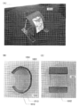
- FIG. 10A is an external view photograph of an electronic device incorporating the lithium ion secondary battery obtained by using Embodiment Mode 1
- FIG. 10B is a photograph of the electronic device taken from the side.
- FIG. 10C is a photograph of the electronic device from the back.
- FIG. 11 is a structural schematic diagram of the electronic device as viewed from the side.
- the 10 and 11 is a display device that can be worn on the arm, and can display images and information. Since the lithium ion secondary battery uses flexibility, a shape suitable for the arm can be realized. The appearance is also excellent in design and can be used as an accessory.
- the 10 and 11 includes a support structure 1001, a secondary battery 1002, a control board 1004, a display module 1011, a protective member 1013, and a cover 1012.
- the support structure 1001 includes the secondary battery 1002
- the secondary battery 1002 includes the control board 1004
- the protection member 1013 includes the display module. 1011 and a cover 1012.
- the electronic device has an antenna 1005 for wireless charging, and can perform wireless charging according to the Qi standard.
- the electronic device also has a communication device 1007 for wirelessly communicating data used for display with an external device.
- the secondary battery 1002 of one embodiment obtained using Embodiment 1 is a film having a thin and flexible outer body, and is attached to a support structure 1001 having a curved surface, so that the support structure 1001 has a large radius of curvature. It can be deformed following the curved surface portion of the region.
- the secondary battery 1002 in the electronic device, when a plastic substrate having translucency is used for the support structure 1001, the secondary battery 1002 can be visually recognized from the back side of the electronic device. The embossed film surface of the secondary battery 1002 can be observed.
- the support structure 1001 is flexible. Therefore, the support structure 1001 can be easily bent. Note that a material other than plastic can be used for the support structure 1001.
- the shape of the support structure 1001 is a bracelet type in which a band-like structure is curved. Further, at least a part of the support structure 1001 has flexibility, and the support structure 1001 can be fitted to the wrist while the support structure 1001 is deformed.
- the protective member 1013 protects the internal structure of the electronic device, particularly the control board 1004, from an unexpected impact from the outside.
- the same material as the support structure 1001 can be used.
- a material different from that of the support structure 1001 may be used for the material of the protection member 1013.
- the cover 1012 is a light-shielding film in which an adhesive is applied to one surface, and has a function of wrapping the entire electronic device and integrating each structure, and has an opening in the display portion 1015. Since the cover 1012 has a light shielding property, the internal structure can be hidden, and the design of the electronic device can be improved. However, the electronic device may have a design intended to allow the internal structure to be visually recognized from the outside. When the design is adopted, the cover 1012 may not have light shielding properties. Further, even when the protective member 1013 has a light shielding property, the cover 1012 may not have a light shielding property.
- the control board 1004 has a slit to bend, and includes a communication device 1007, a microcomputer, a storage device, an FPGA, a DA converter, a charge control IC, a level shifter, and the like of the Bluetooth (registered trademark, same as IEEE802.15.1) standard. The configuration is provided.
- the control board 1004 is connected to the display module 1011 having the display unit 1015 through the input / output connector 1014.
- the control board 1004 is connected to the antenna 1005 through the wiring 1008 and is connected to the secondary battery 1002 through the wiring 1003 and the connection portion 1010.
- a power supply control circuit 1006 controls charging / discharging of the secondary battery 1002.
- the display module 1011 indicates a display panel attached up to at least the FPC 1009.
- the electronic device illustrated in FIG. 11 preferably includes a display portion 1015, an FPC 1009, and a driver circuit, and further includes a converter for supplying power from the secondary battery 1002.
- the display portion 1015 has flexibility, and a display element is provided over a flexible film.
- the secondary battery 1002 and the display portion are preferably arranged at a partly overlapping position, and the power path from the secondary battery 1002 to the display unit 1015 is shortened by arranging at a partly or entirely overlapping position, that is, Shorten wiring distance and reduce power consumption.
- the display module between the protective member 1013 and the cover 1011 the display module 1011 can be protected from unexpected deformation such as wrinkles and twists, and the life of the electronic device as a product can be improved. it can.
- a method for manufacturing a display element on a flexible film a method of directly manufacturing a display element on a flexible film or a layer including a display element on a rigid substrate such as a glass substrate is formed. Then, after removing the substrate by etching or polishing, a method of bonding the layer including the display element and a flexible film, or providing a release layer on a rigid substrate such as a glass substrate, and displaying on it. There is a method in which after a layer including an element is formed, a substrate having rigidity and a layer including a display element are separated using a peeling layer, and the layer including the display element and a flexible film are bonded.
- a touch panel may be mounted on the display portion 1015 so that information input and operation to the electronic device can be performed using the touch panel.
- the content (may be a part of content) described in one embodiment is different from the content (may be a part of content) described in the embodiment and / or one or more Application, combination, replacement, or the like can be performed on the content described in another embodiment (or part of the content).
- a drawing (or a part thereof) described in one embodiment may be another part of the drawing, another drawing (may be a part) described in the embodiment, and / or one or more. More diagrams can be formed by combining the diagrams (may be a part) described in another embodiment.
- regulated removing the content can be comprised.
- a numerical value range indicated by an upper limit value and a lower limit value is described for a certain value, the range is unified by arbitrarily narrowing the range or by removing one point in the range.
- One aspect of the invention excluding a part can be defined. Thus, for example, it can be defined that the prior art does not fall within the technical scope of one embodiment of the present invention.
- an active material layer is not formed over the current collector. Therefore, equipment required for the step of providing an active material on the negative electrode current collector, that is, a kneading device for producing a slurry, a coater for coating the slurry, a dryer for drying the slurry, etc. A device or the like is unnecessary. Therefore, when these apparatuses are used, the time required for each process can be omitted. Furthermore, the cost of members, such as an active material, a conductive support agent, and a binder, did not start. Furthermore, it is not necessary to consider the yield of the process of providing the active material on the negative electrode current collector, and the yield can be increased throughout the manufacturing process of the secondary battery.
- LiFePO 4 as the active material
- graphene oxide (GO) as the conductive auxiliary agent
- PVDF as the binder
- LiFePO 4 : GO: PVDF 94.4: 0.6: 5 (weight%)
- NMP N-methyl-2-pyrrolidone
- the prepared slurry was applied to an aluminum current collector (20 ⁇ m) that had been previously coated with an undercoat, and then dried.
- a continuous coating machine was used, the coating method was a slot die, the supply method was a metering pump, and the coating speed was 1.0 m / min. Drying was performed at 80 ° C. under atmospheric pressure until NMP was completely evaporated. Thereafter, chemical reduction of graphene oxide was performed.
- graphene oxide was reduced by reaction in a solvent containing a reducing agent.
- the reduction treatment was performed at 60 ° C. for 4.5 hours.
- Ascorbic acid was used as a reducing agent.
- ethanol was used as the solvent, and the concentration of the reducing agent was 13.5 g / L. Thereafter, it was washed with ethanol and dried at 70 ° C. for 10 hours. Drying was performed in a vacuum atmosphere.
- the positive electrode active material layer was formed by pressing and compacting by a roll press method.
- a secondary battery was produced using the produced positive electrode and negative electrode.
- a coin-type secondary battery of CR2032 type (diameter 20 mm, height 3.2 mm) was used.
- the separator was used by laminating polypropylene having a thickness of 25 ⁇ m on the positive electrode side and cellulose fiber on the negative electrode side.
- the positive electrode and the negative electrode those having an area of 1.13 cm 2 were used.
- the positive electrode can and the negative electrode can those formed of stainless steel (SUS) were used.
- electrolytic solution three types of electrolytic solution A, electrolytic solution B, and comparative electrolytic solution A were prepared.
- a mixed solvent in which EC (ethylene carbonate) and DEC (diethyl carbonate) were mixed at a volume ratio of 1: 1 was used as the solvent of each electrolytic solution.
- lithium hexafluorophosphate (LiPF 6 ) was dissolved at a concentration of about 1 mol / liter to prepare an electrolytic solution A, and a secondary battery A was manufactured using the electrolytic solution A.
- an electrolytic solution B was prepared by dissolving lithium tetrafluoroborate (LiBF 4 ) in a mixed solvent at a concentration of about 1 mol / liter, and a secondary battery B was manufactured using the electrolytic solution B.
- a comparative electrolytic solution A is prepared by mixing lithium perchlorate (LiClO 4 ) in a mixed solvent at a concentration of about 1 mol / liter, and a comparative secondary battery A is manufactured using the comparative electrolytic solution A. did.
- charging / discharging of each of the produced three types of thin secondary batteries was performed. Charging / discharging was carried out at a constant current of 1.7 mA, the charging / discharging upper limit voltage was 4V, and the lower limit voltage was 2V. Moreover, charging / discharging was performed on 25 degreeC temperature conditions.
- FIG. 3A is an SEM observation image of a negative electrode taken out from a secondary battery (secondary battery A) having lithium hexafluorophosphate (LiPF 6 ) as a salt in an electrolytic solution
- FIG. is an SEM observation image of the negative electrode taken out from the secondary battery having lithium tetrafluoroborate (LiBF 4) as a salt in the electrolyte (secondary battery B).
- FIG. 12A is an SEM observation image of a negative electrode taken out from a secondary battery (comparative secondary battery A) having lithium perchlorate (LiClO 4 ) as a salt in the electrolytic solution.
- a lithium ion secondary battery which does not use an active material for a negative electrode which is one embodiment of the present invention will be described with respect to lithium deposited on the surface of the negative electrode current collector during charging and analyzed by XPS.
- a secondary battery manufactured in this example will be described.
- the manufacturing conditions for the positive electrode and the negative electrode are the same as the manufacturing conditions for the positive electrode and the negative electrode shown in Example 1, and a description thereof will be omitted. Since the production conditions of the secondary battery other than the production conditions of the electrolytic solution are the same as the production conditions shown in Example 1, the description is omitted except for a part.
- the electrolyte used for the secondary battery manufactured in this example will be described. Two types of electrolytic solutions, electrolytic solution C and electrolytic solution D, were used.
- the electrolytic solution C uses a mixed solvent in which EC and DEC are mixed at a volume ratio of 3: 7 as a solvent, and lithium hexafluorophosphate (LiPF 6 ) is dissolved in the mixed solvent at a concentration of 1 mol / liter. Made.
- a secondary battery C was produced using the electrolytic solution C.
- the electrolyte D uses a mixed solvent in which EC and DEC are mixed at a volume ratio of 1: 1 as a solvent, and lithium tetrafluoroborate (LiBF 4 ) is about 1 mol / liter in the mixed solvent. It was prepared by dissolving at a concentration. A secondary battery D was produced using the electrolytic solution D.
- each of the two types of thin secondary batteries produced was charged and discharged. Charging / discharging was carried out at a constant current of 1.7 mA.
- the upper limit voltage of charge / discharge was 4V, and the lower limit voltage was 2V.
- charging / discharging was performed on 25 degreeC temperature conditions.
- FIG. 2 is an XPS spectrum in a region where a peak attributed to lithium fluoride appears. From the surface of the negative electrode taken out from the secondary battery D, a peak attributed to lithium fluoride was strongly observed. Also, a peak attributed to lithium fluoride was observed from the surface of the negative electrode taken out from the secondary battery C, although it was relatively small. From this analysis, it was confirmed that both batteries contained lithium fluoride on the surface of lithium deposited on the negative electrode surface. In addition, the amount of the negative electrode of the secondary battery D using lithium tetrafluoroborate (LiBF 4 ) is larger than that of the secondary battery C using lithium hexafluorophosphate (LiPF 6 ). It was confirmed that there were many.
- LiBF 4 lithium tetrafluoroborate
- LiPF 6 lithium hexafluorophosphate
- a secondary battery manufactured in this example will be described. About the negative electrode, since it is the same as the conditions shown in Example 1, description is abbreviate
- the produced slurry was applied to an aluminum current collector (20 ⁇ m) that had been previously undercoated, and then dried. Drying was performed at 80 ° C. under atmospheric pressure, and drying was performed until NMP was completely evaporated. Next, the positive electrode active material layer was pressed by a roll press method to be consolidated.
- the electrolyte used for the secondary battery manufactured in this example will be described.
- the electrolytic solution two types of electrolytic solution E and electrolytic solution F were used.
- the electrolytic solution E uses a mixed solvent in which EC and DEC are mixed at a volume ratio of 1: 1 as a solvent, and lithium hexafluorophosphate (LiPF 6 ) is dissolved in the mixed solvent at a concentration of 1 mol / liter. Made.
- a secondary battery E was produced using the electrolytic solution E.
- the electrolytic solution F uses a mixed solvent in which EC and DEC are mixed at a volume ratio of 1: 1 as a solvent, and lithium tetrafluoroborate (LiBF 4 ) is dissolved in the mixed solvent at a concentration of 1 mol / liter. Made. A secondary battery F was produced using the electrolytic solution F.
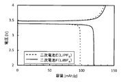
- the initial discharge capacity is such that the secondary battery F using lithium tetrafluoroborate (LiBF 4 ) as the electrolytic solution uses lithium hexafluorophosphate (LiPF 6 ) as the electrolytic solution. It was confirmed that the discharge capacity was higher than that of the secondary battery E.
- lithium tetrafluoroborate (LiBF 4 ) is chemically less stable and more easily decomposed than lithium hexafluorophosphate (LiPF 6 ).
- the discharge capacity is also relatively low.
- the secondary battery F using lithium tetrafluoroborate (LiBF 4 ) as the electrolytic solution has lithium hexafluorophosphate (LiPF 6 ) as the electrolytic solution.
- the discharge capacity was relatively higher than that of the secondary battery E used.
- Examples 1 to 3 The results shown in Examples 1 to 3 are summarized. That is, when lithium tetrafluoroborate (LiBF 4 ) in the electrolytic solution is partially decomposed, fluorine is provided to lithium deposited on the surface of the negative electrode current collector to form lithium fluoride. Lithium fluoride formed on the negative electrode surface suppresses the formation of dendritic (whisker-like) lithium in further charging of the secondary battery. As a result, lithium which does not contribute to the battery reaction due to elution of whisker roots during discharge can be suppressed, and the discharge capacity can be maintained without loss. Therefore, lithium hexafluorophosphate (LiPF 6 ) The discharge capacity is larger than
- lithium hexafluorophosphate LiPF 6
- the formation of lithium fluoride is confirmed on the surface by the result of XPS. It can be confirmed that it is enjoyed.
- a lithium ion secondary battery in which ethylene carbonate containing fluorine is added to an electrolytic solution as an additive, which is one embodiment of the present invention, and an active material is not used for a negative electrode will be described.
- a secondary battery manufactured in this example will be described.
- the negative electrode since it is the same as the conditions shown in Example 1, description is abbreviate
- the positive electrode since it is the same as the conditions shown in Example 3, description is abbreviate
- the electrolytic solution G-2 was prepared by adding and mixing FEC at a weight of 2 wt% with respect to the weight of the solution.
- the electrolytic solution G-3 was prepared by adding FEC at a weight of 20 wt% with respect to the weight of the solution and mixing them.
- the electrolytic solution G-4 was prepared by adding FEC at a weight of 50 wt% with respect to the weight of the solution and mixing.
- Electrolytic solution G-1 is a solution to which FEC is not added.
- Secondary batteries G-1 to secondary batteries G-4 were produced using the electrolytic solutions G-1 to G-4.
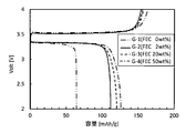
- the discharge capacity is significantly improved by adding FEC to the electrolyte of the secondary battery.
- the effect of adding FEC appears from the addition weight of 2 wt%, and the effect is more remarkable at the addition weight of 20 wt%. Although the effect tends to be saturated when the added weight is 50 wt%, it has been confirmed that the discharge capacity is improved as the added weight of FEC is increased.
- FEC supplies fluorine to the lithium deposited by charging on the surface of the negative electrode current collector, and lithium fluoride is formed on the surface of the deposited lithium. Is suppressed in the dendrite form (whisker form), the lithium lost as lithium that does not contribute to the battery reaction is reduced, and the reduction in the discharge capacity is suppressed.
- FIG. 12B shows the result of SEM observation in which the surface of the negative electrode was observed with a scanning electron microscope (SEM). In FIG. 12B, no precipitation of dendritic (whisker-like) lithium was confirmed on the current collector taken out from the secondary battery G-3.
- Fluorine is supplied not only to lithium tetrafluoroborate (LiBF 4 ) in the electrolyte but also to lithium on the negative electrode surface from FEC, and lithium fluoride is formed, so that dendritic (whisker-like) lithium Formation was suppressed.
- Fluorine may be included in the salt of the electrolytic solution or may be included as an additive of the electrolytic solution.
Landscapes
- Chemical & Material Sciences (AREA)
- Chemical Kinetics & Catalysis (AREA)
- Electrochemistry (AREA)
- General Chemical & Material Sciences (AREA)
- Engineering & Computer Science (AREA)
- Manufacturing & Machinery (AREA)
- Inorganic Chemistry (AREA)
- Materials Engineering (AREA)
- Condensed Matter Physics & Semiconductors (AREA)
- General Physics & Mathematics (AREA)
- Physics & Mathematics (AREA)
- Secondary Cells (AREA)
- Battery Electrode And Active Subsutance (AREA)
- Cell Separators (AREA)
- Cell Electrode Carriers And Collectors (AREA)
Abstract
Description
本発明の一態様にかかるリチウムイオン二次電池110の作製方法について図1(A)及び(B)を用い、以下に説明する。図1(B)は、リチウムイオン二次電池110の断面図である。正極集電体101aと、正極活物質層101bと、セパレータ104と、負極集電体102とを積み重ね、電解液105とともに外装体106により封止された状態の断面模式図である。なお、二次電池を積層構造とすることも可能である。正極101は、正極集電体101aと、正極活物質層101bが含まれるが、負極は、負極活物質層を有さない。そのため、負極集電体102が負極を構成する主要な部材である。負極集電体102はセパレータ104と直接接する場合もあり、その場合、負極集電体102はセパレータ104の有する開孔に存在する電解液105と直接接触する。一方で、セパレータ104と負極集電体102が接触しない場合、電解液105は負極集電体102が有する少なくともひとつの面の全域において負極集電体102と接触する。
本実施の形態においては、先の実施の形態で説明した二次電池を有する電子機器の一例について図9を用いて説明を行う。
本実施の形態では、実施の形態1を用いて得られるリチウムイオン二次電池を組み込んだ電子機器の一例を示す。図10(A)は、実施の形態1を用いて得られるリチウムイオン二次電池を組み込んだ電子機器の外観写真図であり、図10(B)は、該電子機器を側面から撮影した写真図であり、図10(C)は該電子機器を背面からの写真図である。図11は、該電子機器を側面から見たときの構造模式図である。
まず、負極について説明する。負極には、集電体として圧延銅箔集電体(18μm)を用いた。
次に、作製した正極および負極を用いて、二次電池を作製した。特性の評価にはCR2032タイプ(直径20mm、高さ3.2mm)のコイン型の二次電池を用いた。セパレータには正極側に25μm厚のポリプロピレンと、負極側にセルロース繊維を積層して用いた。正極、負極は、1.13cm2の面積のものを用いた。正極缶及び負極缶として、ステンレス鋼(SUS)で形成されているものを用いた。
初回充電において、上限電圧である4Vに達した所で電池動作を停止させ、電池を解体して、リチウムが析出した状態の負極を取り出し、洗浄を行った。洗浄液には、ジメチルカーボネートを用いた。この負極の表面を、走査型電子顕微鏡(SEM:Scanning Electron Microscope)により観察を行った。SEM観察の結果を図3及び図12(A)に示す。
本実施例にて作製した二次電池に用いた電解液について説明する。電解液は、電解液C及び電解液Dの2種類を用いた。電解液Cは、溶媒としてECとDECが体積比で3:7の割合で混合した混合溶媒を用い、混合溶媒に六フッ化リン酸リチウム(LiPF6)を1モル/リットルの濃度で溶解させて作製した。電解液Cを用いて二次電池Cを作製した。また、電解液Dは、溶媒としてECとDECが体積比で1:1の割合で混合した混合溶媒を用い、混合溶媒中に四フッ化ホウ酸リチウム(LiBF4)を約1モル/リットルの濃度で溶解させて作製した。電解液Dを用いて二次電池Dを作製した。
初回充電において、上限電圧である4Vに達した所で電池動作を停止させ、電池を解体して、リチウムが析出した状態の負極を取り出し、洗浄を行った。洗浄液には、ジメチルカーボネートを用いた。この負極の表面を、X線光電子分光法(XPS)を用いて分析を行った結果を図2に示す。
まず、LiFePO4、アセチレンブラック(以下ABとする)及びPVDFを、LiFePO4:AB:PVDF=90:5:5(weight%)の割合で配合し、溶媒としてNMPを用いて正極用のスラリーを作製した。
本実施例にて作製した二次電池に用いた電解液について説明する。電解液として、電解液E、電解液Fの2種類を用いた。電解液Eは、溶媒としてECとDECが体積比で1:1の割合で混合した混合溶媒を用い、混合溶媒中に六フッ化リン酸リチウム(LiPF6)を1モル/リットルの濃度で溶解させて作製した。電解液Eを用いて二次電池Eを作製した。電解液Fは、溶媒としてECとDECが体積比で1:1の割合で混合した混合溶媒を用い、混合溶媒中に四フッ化ホウ酸リチウム(LiBF4)を1モル/リットルの濃度で溶解させて作製した。電解液Fを用いて二次電池Fを作製した。
次に、作製した二次電池の充放電を行った。充放電は、1.7mAの電流で定電流充放電した。充放電の上限電圧を4V、下限電圧は2Vとした。また、充放電は25℃の温度で行い、充放電を繰り返し行った。初回の充放電特性を図4に示す。
本実施例にて作製した二次電池に用いた電解液Gについて説明する。まず、溶媒としてPC(プロピレンカーボネート)を用い、溶媒に四フッ化ホウ酸リチウム(LiBF4)を1モル/リットルの濃度で溶解させた。作製した溶液に、4種類の条件でFEC(フルオロエチレンカーボネート)を添加剤として加え、電解液G−1乃至電解液G−4を作製した。
次に、作製した二次電池の充放電を行った。充放電は、1.7mAの電流で定電流充放電した。充放電の上限電圧を4V、下限電圧は2Vとした。また、充放電は25℃の温度で行い、充放電を繰り返し行った。初回の充放電特性を図5に示す。サイクル特性を図6に示す。
また、二次電池G−3と同条件で二次電池を作製し、初回充電において、上限電圧である4Vに達した所で電池動作を停止させ、電池を解体して、リチウムが析出した状態の負極を取り出し、洗浄を行った。洗浄液には、ジメチルカーボネートを用いた。この負極の表面を、走査型電子顕微鏡(SEM:Scanning Electron Microscope)により観察を行った、SEM観察の結果を図12(B)に示す。図12(B)に、二次電池G−3から取り出した集電体上には、デンドライト状(ウィスカー状)のリチウムの析出は確認されなかった。電解液中の四フッ化ホウ酸リチウム(LiBF4)だけでなく、FECからも負極表面のリチウムにフッ素が供給され、フッ化リチウムが形成されたことにより、デンドライト状(ウィスカー状)のリチウムの形成が抑制された。
101a 正極集電体
101b 正極活物質層
102 負極集電体
104 セパレータ
105 電解液
106 外装体
108 スペーサ
110 リチウムイオン二次電池
115 リード電極
116 封止部
200 デンドライト(ウィスカー)
800 携帯電話機
801 筐体
802 表示部
803 操作ボタン
804 二次電池
805 スピーカ
806 マイク
1001 支持構造体
1002 二次電池
1003 配線
1004 制御基板
1005 アンテナ
1006 電源制御回路
1007 通信装置
1008 配線
1009 FPC
1010 接続部
1011 表示モジュール
1012 カバー
1013 保護部材
1014 入出力コネクタ
1015 表示部
1700 曲面
1701 平面
1702 曲面の形状である曲線
1703 曲率半径
1704 曲率中心
1800 曲率中心
1801 フィルム
1802 曲率半径
1803 フィルム
1804 曲率半径
1805 電極・電解液など
7100 携帯表示装置
7101 筐体
7102 表示部
7103 操作ボタン
7104 二次電池
7200 腕章型表示装置
7201 筐体
7202 表示部
Claims (10)
- 正極と、負極と、電解液と、
前記正極と前記負極との間のセパレータと、を有し、
前記負極は、負極集電体を有し、
前記負極集電体は、前記電解液若しくは前記セパレータの少なくとも一方と直接接する領域を有し、
前記電解液は、フッ素を有しており、
前記負極集電体は、充電時にリチウムを有する析出物が表面に析出することができる機能を有するリチウムイオン二次電池。 - 請求項1において、
更に前記セパレータと前記負極との間のスペーサを有し、
前記スペーサは負極集電体と直接接するリチウムイオン二次電池。 - 正極と、負極と、電解液と、
前記正極と前記負極との間のセパレータと、
前記セパレータと前記負極との間のシート状のスペーサと、を有し、
前記シート状のスペーサは、前記セパレータよりも空隙率が高く、
前記負極は、負極集電体を有し、
前記負極集電体は、前記スペーサと直接接し、
前記電解液は、フッ素を有しており、
前記セパレータと前記負極集電体との間の領域においてリチウムを有する析出物が析出することができる機能を有するリチウムイオン二次電池。 - 正極と、負極と、電解液と、
前記正極と前記負極との間のセパレータと、
前記セパレータと前記負極との間のスペーサと、を有し、
前記負極は、負極集電体を有し、
前記負極集電体は、前記スペーサと直接接し、
前記電解液は、フッ素を有しており、
前記正極、前記負極、前記セパレータ、及び前記スペーサは可撓性を有し、
前記セパレータと前記負極集電体との間の領域においてリチウムを有する析出物が析出することができる機能を有するリチウムイオン二次電池。 - 請求項1乃至請求項4において、
前記フッ素は、前記電解液中の有機化合物又は無機塩に含まれており、
前記電解液において、前記有機化合物又は無機塩は、前記電解液の重量に対して2wt%以上の重量で存在するリチウムイオン二次電池。 - 請求項5において、
前記有機化合物はフルオロエチレンカーボネートであるリチウムイオン二次電池。 - 請求項5において、
前記無機塩は、四フッ化ホウ酸リチウムまたは六フッ化リン酸リチウムであるリチウムイオン二次電池。 - 請求項1乃至請求項4のいずれか一において、
前記負極は活物質層を有さないリチウムイオン二次電池。 - 請求項1乃至請求項4のいずれか一において、
前記負極集電体は、銅を有するリチウムイオン二次電池。 - 請求項1乃至請求項4のいずれか一において、
前記リチウムを有する析出物は、フッ化リチウムである、リチウムイオン二次電池。
Priority Applications (5)
| Application Number | Priority Date | Filing Date | Title |
|---|---|---|---|
| KR1020167028575A KR102341434B1 (ko) | 2014-03-24 | 2015-03-12 | 리튬 이온 이차 전지 |
| JP2016509598A JPWO2015145288A1 (ja) | 2014-03-24 | 2015-03-12 | リチウムイオン二次電池 |
| US15/127,290 US10483522B2 (en) | 2014-03-24 | 2015-03-12 | Lithium-ion secondary battery |
| CN201580016096.3A CN106550615B (zh) | 2014-03-24 | 2015-03-12 | 锂离子二次电池 |
| CN202110189307.0A CN113113660B (zh) | 2014-03-24 | 2015-03-12 | 锂离子二次电池 |
Applications Claiming Priority (2)
| Application Number | Priority Date | Filing Date | Title |
|---|---|---|---|
| JP2014-059420 | 2014-03-24 | ||
| JP2014059420 | 2014-03-24 |
Publications (1)
| Publication Number | Publication Date |
|---|---|
| WO2015145288A1 true WO2015145288A1 (ja) | 2015-10-01 |
Family
ID=54194041
Family Applications (1)
| Application Number | Title | Priority Date | Filing Date |
|---|---|---|---|
| PCT/IB2015/051793 Ceased WO2015145288A1 (ja) | 2014-03-24 | 2015-03-12 | リチウムイオン二次電池 |
Country Status (5)
| Country | Link |
|---|---|
| US (1) | US10483522B2 (ja) |
| JP (4) | JPWO2015145288A1 (ja) |
| KR (1) | KR102341434B1 (ja) |
| CN (2) | CN106550615B (ja) |
| WO (1) | WO2015145288A1 (ja) |
Cited By (15)
| Publication number | Priority date | Publication date | Assignee | Title |
|---|---|---|---|---|
| WO2018012376A1 (ja) * | 2016-07-14 | 2018-01-18 | パナソニック株式会社 | リチウム二次電地 |
| KR20180067586A (ko) * | 2015-11-18 | 2018-06-20 | 센젠 인스티튜트스 오브 어드밴스트 테크놀로지, 차이니즈 아카데미 오브 사이언시스 | 이차전지 및 그 제조방법 |
| JP2019501478A (ja) * | 2016-05-06 | 2019-01-17 | リアル パワー インダストリアル リミテッド カンパニー | 二次電池及びその製造方法 |
| WO2019087709A1 (ja) * | 2017-10-30 | 2019-05-09 | パナソニックIpマネジメント株式会社 | 非水電解質二次電池及びその製造方法 |
| CN109937504A (zh) * | 2017-03-28 | 2019-06-25 | 松下知识产权经营株式会社 | 非水电解质二次电池 |
| JP2019526151A (ja) * | 2016-07-11 | 2019-09-12 | ボード・オブ・リージエンツ,ザ・ユニバーシテイ・オブ・テキサス・システム | 金属めっきベースの電気エネルギー貯蔵セル |
| JP2019175568A (ja) * | 2018-03-27 | 2019-10-10 | 本田技研工業株式会社 | リチウムイオン二次電池 |
| CN110556512A (zh) * | 2018-05-31 | 2019-12-10 | 松下知识产权经营株式会社 | 锂二次电池 |
| JP2020198297A (ja) * | 2019-05-30 | 2020-12-10 | パナソニックIpマネジメント株式会社 | 二次電池 |
| JPWO2021229635A1 (ja) * | 2020-05-11 | 2021-11-18 | ||
| WO2022091407A1 (ja) * | 2020-11-02 | 2022-05-05 | TeraWatt Technology株式会社 | リチウム2次電池 |
| CN114665153A (zh) * | 2021-12-21 | 2022-06-24 | 浙江金羽新能源科技有限公司 | 含添加剂的锌离子电池电解液及其制备方法和锌离子电池 |
| JPWO2022215160A1 (ja) * | 2021-04-06 | 2022-10-13 | ||
| JP2023503030A (ja) * | 2019-11-25 | 2023-01-26 | ゼリオン アドバンスド バッテリー コーポレイション | 自己パッケージ化電池 |
| WO2025070578A1 (ja) * | 2023-09-28 | 2025-04-03 | パナソニックIpマネジメント株式会社 | 二次電池 |
Families Citing this family (25)
| Publication number | Priority date | Publication date | Assignee | Title |
|---|---|---|---|---|
| KR101984722B1 (ko) | 2016-07-21 | 2019-05-31 | 주식회사 엘지화학 | 리튬 코발트 산화물을 합성하기 위한 양극 활물질을 포함하는 리튬 이차전지, 이의 제조방법 |
| WO2018236168A1 (ko) | 2017-06-21 | 2018-12-27 | 주식회사 엘지화학 | 리튬 이차전지 |
| WO2018236166A1 (ko) | 2017-06-21 | 2018-12-27 | 주식회사 엘지화학 | 리튬 이차전지 |
| KR102115602B1 (ko) | 2017-06-21 | 2020-05-26 | 주식회사 엘지화학 | 리튬 이차전지 |
| KR102093971B1 (ko) | 2017-06-21 | 2020-05-21 | 주식회사 엘지화학 | 리튬 이차전지 |
| KR102093972B1 (ko) | 2017-06-26 | 2020-03-26 | 주식회사 엘지화학 | 리튬 이차전지 |
| CN109148959B (zh) * | 2017-06-28 | 2023-07-25 | 松下知识产权经营株式会社 | 锂二次电池 |
| KR102268176B1 (ko) | 2017-08-28 | 2021-06-22 | 주식회사 엘지에너지솔루션 | 리튬 이차전지 |
| JP6962070B2 (ja) | 2017-08-29 | 2021-11-05 | スズキ株式会社 | 空気電池およびそれに用いる負極複合体 |
| US11581523B2 (en) * | 2017-10-19 | 2023-02-14 | Sila Nanotechnologies, Inc. | Anode electrode composition of Li-ion battery cell |
| KR102639661B1 (ko) | 2018-06-21 | 2024-02-21 | 주식회사 엘지에너지솔루션 | 리튬 이차전지 |
| EP3823073B1 (en) | 2018-10-30 | 2025-12-10 | LG Energy Solution, Ltd. | Lithium secondary battery |
| CN111837257B (zh) | 2018-10-31 | 2023-10-24 | 株式会社Lg新能源 | 锂二次电池 |
| PL3761405T3 (pl) | 2018-10-31 | 2026-05-11 | Lg Energy Solution, Ltd. | Litowa bateria akumulatorowa |
| WO2020091515A1 (ko) | 2018-11-02 | 2020-05-07 | 주식회사 엘지화학 | 리튬 이차전지 |
| WO2020146446A1 (en) * | 2019-01-08 | 2020-07-16 | SF Motors Inc. | Systems and methods to control lithium plating |
| US11462804B2 (en) | 2019-01-08 | 2022-10-04 | TeraWatt Technology Inc. | Systems and methods to control lithium plating |
| CN110085871B (zh) * | 2019-06-03 | 2021-12-10 | 哈尔滨工业大学 | 一种改性金属锂负极集流体的制备方法及其应用 |
| TWI709262B (zh) * | 2019-11-11 | 2020-11-01 | 國立臺灣科技大學 | 非水性電解液以及包括其的鋰金屬二次電池與鋰離子二次電池 |
| EP3902052A1 (en) | 2020-04-22 | 2021-10-27 | Solvay SA | Anode-less lithium battery |
| CN115516689A (zh) | 2020-05-22 | 2022-12-23 | 株式会社半导体能源研究所 | 二次电池及包括二次电池的车辆 |
| KR20230017795A (ko) | 2020-05-29 | 2023-02-06 | 가부시키가이샤 한도오따이 에네루기 켄큐쇼 | 이차 전지 및 차량 |
| US20240047764A1 (en) * | 2020-11-20 | 2024-02-08 | Lg Energy Solution, Ltd. | Lithium-free secondary battery |
| CN114597515A (zh) * | 2020-12-07 | 2022-06-07 | 恒大新能源技术(深圳)有限公司 | 负极及其制备方法、锂二次电池 |
| CN120809974B (zh) * | 2025-09-11 | 2025-11-25 | 福建新峰二维材料科技有限公司 | 磷酸锰铁锂二次电池与装置 |
Citations (5)
| Publication number | Priority date | Publication date | Assignee | Title |
|---|---|---|---|---|
| JPH0536401A (ja) * | 1991-07-30 | 1993-02-12 | Japan Storage Battery Co Ltd | リチウム二次電池 |
| JP2001068162A (ja) * | 1999-08-24 | 2001-03-16 | Matsushita Electric Ind Co Ltd | 非水電解質二次電池およびその充放電方法 |
| JP2002298921A (ja) * | 2001-03-28 | 2002-10-11 | Sanyo Electric Co Ltd | 二次電池 |
| JP2012018914A (ja) * | 2010-06-02 | 2012-01-26 | Semiconductor Energy Lab Co Ltd | 蓄電装置 |
| JP2014035956A (ja) * | 2012-08-09 | 2014-02-24 | Mitsubishi Chemicals Corp | 非水系電解質、およびそれを用いた非水系電解質二次電池 |
Family Cites Families (33)
| Publication number | Priority date | Publication date | Assignee | Title |
|---|---|---|---|---|
| JPS59181587U (ja) * | 1983-05-20 | 1984-12-04 | 日立マクセル株式会社 | リチウム二次電池 |
| JPH0230060A (ja) * | 1987-11-11 | 1990-01-31 | Ricoh Co Ltd | 二次電池用負極 |
| JP3200867B2 (ja) | 1991-04-26 | 2001-08-20 | ソニー株式会社 | 非水電解質二次電池 |
| JP3371301B2 (ja) * | 1994-01-31 | 2003-01-27 | ソニー株式会社 | 非水電解液二次電池 |
| JP3717085B2 (ja) * | 1994-10-21 | 2005-11-16 | キヤノン株式会社 | 二次電池用負極、該負極を有する二次電池及び電極の作製方法 |
| JPH08329984A (ja) | 1995-06-01 | 1996-12-13 | Fujitsu Ltd | 非水電解質二次電池 |
| US6365299B1 (en) | 1995-06-28 | 2002-04-02 | Fuji Photo Film Co., Ltd. | Nonaqueous secondary battery |
| JPH1012279A (ja) * | 1996-04-26 | 1998-01-16 | Denso Corp | 金属リチウム2次電池 |
| US6506524B1 (en) | 1996-10-03 | 2003-01-14 | National Research Council Of Canada | Electrolyte comprising fluoro-ethylene carbonate and propylene carbonate, for alkali metal-ion secondary battery |
| JP4086444B2 (ja) * | 2000-03-08 | 2008-05-14 | 三洋電機株式会社 | リチウム二次電池 |
| WO2006033358A1 (ja) * | 2004-09-22 | 2006-03-30 | Sony Corporation | 電解液および電池 |
| WO2006093049A1 (ja) * | 2005-03-02 | 2006-09-08 | Matsushita Electric Industrial Co., Ltd. | リチウムイオン二次電池およびその製造法 |
| JP5260821B2 (ja) * | 2005-07-11 | 2013-08-14 | パナソニック株式会社 | リチウムイオン二次電池 |
| JP5036161B2 (ja) | 2005-10-14 | 2012-09-26 | パナソニック株式会社 | リチウムイオン二次電池用負極活物質、その製造方法、およびそれを用いたリチウムイオン二次電池 |
| WO2007116926A1 (ja) | 2006-04-05 | 2007-10-18 | Panasonic Corporation | 二次電池の製造方法および二次電池用正極活物質の調製方法 |
| JP2008108689A (ja) | 2006-09-29 | 2008-05-08 | Sanyo Electric Co Ltd | 非水電解質二次電池 |
| JP4544270B2 (ja) * | 2007-05-21 | 2010-09-15 | ソニー株式会社 | 二次電池用電解液および二次電池 |
| KR20090107425A (ko) * | 2008-04-08 | 2009-10-13 | 소니 가부시끼 가이샤 | 부극 및 2차 전지 |
| US8557437B2 (en) | 2009-03-25 | 2013-10-15 | Tdk Corporation | Electrode comprising protective layer for lithium ion secondary battery and lithium ion secondary battery |
| WO2011047105A1 (en) * | 2009-10-14 | 2011-04-21 | Research Foundation Of The City University Of New York | Nickel-zinc flow battery |
| JP2010171019A (ja) | 2010-03-08 | 2010-08-05 | Sony Corp | 非水電解質二次電池 |
| KR20120022722A (ko) * | 2010-04-27 | 2012-03-12 | 파나소닉 주식회사 | 비수계 이차전지 및 이것에 이용하는 전극군 |
| JP6051514B2 (ja) * | 2010-12-02 | 2016-12-27 | ソニー株式会社 | 固体電解質電池および正極活物質 |
| CN102082295A (zh) | 2010-12-29 | 2011-06-01 | 东莞市杉杉电池材料有限公司 | 一种锂离子二次电池的电解液 |
| JP5994354B2 (ja) * | 2011-09-05 | 2016-09-21 | ソニー株式会社 | セパレータおよび非水電解質電池、並びに、電池パック、電子機器、電動車両、蓄電装置および電力システム |
| JP6045260B2 (ja) | 2011-09-16 | 2016-12-14 | 株式会社半導体エネルギー研究所 | 蓄電装置 |
| JP6069821B2 (ja) * | 2011-09-28 | 2017-02-01 | ソニー株式会社 | リチウムイオン二次電池 |
| US10298043B2 (en) | 2011-12-23 | 2019-05-21 | Semiconductor Energy Laboratory Co., Ltd. | Method for charging lithium ion secondary battery and battery charger |
| JP2013218967A (ja) * | 2012-04-11 | 2013-10-24 | Panasonic Corp | 非水電解質および非水電解質二次電池 |
| US20140030590A1 (en) * | 2012-07-25 | 2014-01-30 | Mingchao Wang | Solvent-free process based graphene electrode for energy storage devices |
| WO2014024990A1 (ja) | 2012-08-09 | 2014-02-13 | 三菱化学株式会社 | 非水系電解液、およびそれを用いた非水系電解液二次電池 |
| US10367189B2 (en) * | 2014-09-10 | 2019-07-30 | Battelle Memorial Institute | Anode-free rechargeable battery |
| EP3417497B1 (en) * | 2016-02-19 | 2025-03-19 | American Lithium Energy Corporation | Method of forming a battery cell |
-
2015
- 2015-03-12 KR KR1020167028575A patent/KR102341434B1/ko active Active
- 2015-03-12 CN CN201580016096.3A patent/CN106550615B/zh active Active
- 2015-03-12 WO PCT/IB2015/051793 patent/WO2015145288A1/ja not_active Ceased
- 2015-03-12 CN CN202110189307.0A patent/CN113113660B/zh active Active
- 2015-03-12 JP JP2016509598A patent/JPWO2015145288A1/ja not_active Withdrawn
- 2015-03-12 US US15/127,290 patent/US10483522B2/en active Active
-
2019
- 2019-11-22 JP JP2019211220A patent/JP7072551B2/ja active Active
-
2022
- 2022-05-10 JP JP2022077548A patent/JP2022105193A/ja not_active Withdrawn
-
2024
- 2024-11-15 JP JP2024199801A patent/JP2025015698A/ja active Pending
Patent Citations (5)
| Publication number | Priority date | Publication date | Assignee | Title |
|---|---|---|---|---|
| JPH0536401A (ja) * | 1991-07-30 | 1993-02-12 | Japan Storage Battery Co Ltd | リチウム二次電池 |
| JP2001068162A (ja) * | 1999-08-24 | 2001-03-16 | Matsushita Electric Ind Co Ltd | 非水電解質二次電池およびその充放電方法 |
| JP2002298921A (ja) * | 2001-03-28 | 2002-10-11 | Sanyo Electric Co Ltd | 二次電池 |
| JP2012018914A (ja) * | 2010-06-02 | 2012-01-26 | Semiconductor Energy Lab Co Ltd | 蓄電装置 |
| JP2014035956A (ja) * | 2012-08-09 | 2014-02-24 | Mitsubishi Chemicals Corp | 非水系電解質、およびそれを用いた非水系電解質二次電池 |
Cited By (28)
| Publication number | Priority date | Publication date | Assignee | Title |
|---|---|---|---|---|
| KR102091376B1 (ko) * | 2015-11-18 | 2020-04-24 | 센젠 인스티튜트스 오브 어드밴스트 테크놀로지, 차이니즈 아카데미 오브 사이언시스 | 이차전지 및 그 제조방법 |
| KR20180067586A (ko) * | 2015-11-18 | 2018-06-20 | 센젠 인스티튜트스 오브 어드밴스트 테크놀로지, 차이니즈 아카데미 오브 사이언시스 | 이차전지 및 그 제조방법 |
| JP2019501480A (ja) * | 2015-11-18 | 2019-01-17 | シェンチェン・インスティテューツ・オブ・アドバンスド・テクノロジー・チャイニーズ・アカデミー・オブ・サイエンシーズShenzhen Institutes Of Advanced Technology Chinese Academy Of Sciences | 二次電池及びその製造方法 |
| JP2019501478A (ja) * | 2016-05-06 | 2019-01-17 | リアル パワー インダストリアル リミテッド カンパニー | 二次電池及びその製造方法 |
| JP2019526151A (ja) * | 2016-07-11 | 2019-09-12 | ボード・オブ・リージエンツ,ザ・ユニバーシテイ・オブ・テキサス・システム | 金属めっきベースの電気エネルギー貯蔵セル |
| WO2018012376A1 (ja) * | 2016-07-14 | 2018-01-18 | パナソニック株式会社 | リチウム二次電地 |
| JPWO2018012376A1 (ja) * | 2016-07-14 | 2019-05-09 | パナソニック株式会社 | リチウム二次電地 |
| US10651474B2 (en) | 2016-07-14 | 2020-05-12 | Panasonic Corporation | Lithium secondary battery |
| CN109937504A (zh) * | 2017-03-28 | 2019-06-25 | 松下知识产权经营株式会社 | 非水电解质二次电池 |
| US11508987B2 (en) | 2017-10-30 | 2022-11-22 | Panasonic Intellectual Property Management Co., Ltd. | Nonaqueous electrolyte secondary battery and method for producing same |
| WO2019087709A1 (ja) * | 2017-10-30 | 2019-05-09 | パナソニックIpマネジメント株式会社 | 非水電解質二次電池及びその製造方法 |
| JPWO2019087709A1 (ja) * | 2017-10-30 | 2020-11-12 | パナソニックIpマネジメント株式会社 | 非水電解質二次電池及びその製造方法 |
| JP7236645B2 (ja) | 2017-10-30 | 2023-03-10 | パナソニックIpマネジメント株式会社 | 非水電解質二次電池及びその製造方法 |
| JP2019175568A (ja) * | 2018-03-27 | 2019-10-10 | 本田技研工業株式会社 | リチウムイオン二次電池 |
| CN110556512A (zh) * | 2018-05-31 | 2019-12-10 | 松下知识产权经营株式会社 | 锂二次电池 |
| JP2020198297A (ja) * | 2019-05-30 | 2020-12-10 | パナソニックIpマネジメント株式会社 | 二次電池 |
| JP2023503030A (ja) * | 2019-11-25 | 2023-01-26 | ゼリオン アドバンスド バッテリー コーポレイション | 自己パッケージ化電池 |
| JPWO2021229635A1 (ja) * | 2020-05-11 | 2021-11-18 | ||
| WO2021229635A1 (ja) * | 2020-05-11 | 2021-11-18 | TeraWatt Technology株式会社 | リチウム2次電池 |
| JP7619652B2 (ja) | 2020-05-11 | 2025-01-22 | TeraWatt Technology株式会社 | リチウム2次電池 |
| JPWO2022091407A1 (ja) * | 2020-11-02 | 2022-05-05 | ||
| WO2022091407A1 (ja) * | 2020-11-02 | 2022-05-05 | TeraWatt Technology株式会社 | リチウム2次電池 |
| JP7618274B2 (ja) | 2020-11-02 | 2025-01-21 | TeraWatt Technology株式会社 | リチウム2次電池 |
| JPWO2022215160A1 (ja) * | 2021-04-06 | 2022-10-13 | ||
| WO2022215160A1 (ja) * | 2021-04-06 | 2022-10-13 | TeraWatt Technology株式会社 | リチウム2次電池 |
| JP7646241B2 (ja) | 2021-04-06 | 2025-03-17 | TeraWatt Technology株式会社 | リチウム2次電池 |
| CN114665153A (zh) * | 2021-12-21 | 2022-06-24 | 浙江金羽新能源科技有限公司 | 含添加剂的锌离子电池电解液及其制备方法和锌离子电池 |
| WO2025070578A1 (ja) * | 2023-09-28 | 2025-04-03 | パナソニックIpマネジメント株式会社 | 二次電池 |
Also Published As
| Publication number | Publication date |
|---|---|
| CN106550615A (zh) | 2017-03-29 |
| US20170133660A1 (en) | 2017-05-11 |
| JP2022105193A (ja) | 2022-07-12 |
| CN113113660B (zh) | 2025-09-09 |
| CN106550615B (zh) | 2021-03-12 |
| JP2020024956A (ja) | 2020-02-13 |
| JP7072551B2 (ja) | 2022-05-20 |
| CN113113660A (zh) | 2021-07-13 |
| US10483522B2 (en) | 2019-11-19 |
| JPWO2015145288A1 (ja) | 2017-04-13 |
| KR20160138120A (ko) | 2016-12-02 |
| KR102341434B1 (ko) | 2021-12-22 |
| JP2025015698A (ja) | 2025-01-30 |
Similar Documents
| Publication | Publication Date | Title |
|---|---|---|
| JP7072551B2 (ja) | リチウムイオン二次電池 | |
| JP7130016B2 (ja) | 非水系二次電池 | |
| JP6987813B2 (ja) | 可撓性を有する二次電池 | |
| US10147556B2 (en) | Power storage device and electronic device | |
| US10497979B2 (en) | Power storage device and electronic device | |
| KR102297634B1 (ko) | 이차 전지 및 그 제작 방법 | |
| CN104900903B (zh) | 二次电池 | |
| JP6664184B2 (ja) | 電極、及び電極の作製方法 | |
| JP6935459B2 (ja) | 電極およびその製造方法 | |
| KR20150088191A (ko) | 전극, 축전 장치, 및 전자 기기 | |
| JP2016085962A (ja) | 蓄電体および電子機器 | |
| KR20240010740A (ko) | 축전 장치, 축전 장치의 제작 방법, 및 전자 기기 | |
| KR20230038213A (ko) | 전극, 이차 전지, 이동체, 전자 기기, 및 리튬 이온 이차 전지용 전극의 제작 방법 |
Legal Events
| Date | Code | Title | Description |
|---|---|---|---|
| 121 | Ep: the epo has been informed by wipo that ep was designated in this application |
Ref document number: 15768221 Country of ref document: EP Kind code of ref document: A1 |
|
| ENP | Entry into the national phase |
Ref document number: 2016509598 Country of ref document: JP Kind code of ref document: A |
|
| WWE | Wipo information: entry into national phase |
Ref document number: 15127290 Country of ref document: US |
|
| NENP | Non-entry into the national phase |
Ref country code: DE |
|
| ENP | Entry into the national phase |
Ref document number: 20167028575 Country of ref document: KR Kind code of ref document: A |
|
| 122 | Ep: pct application non-entry in european phase |
Ref document number: 15768221 Country of ref document: EP Kind code of ref document: A1 |