WO2015140926A1 - ファン取付部付きシート - Google Patents
ファン取付部付きシート Download PDFInfo
- Publication number
- WO2015140926A1 WO2015140926A1 PCT/JP2014/057357 JP2014057357W WO2015140926A1 WO 2015140926 A1 WO2015140926 A1 WO 2015140926A1 JP 2014057357 W JP2014057357 W JP 2014057357W WO 2015140926 A1 WO2015140926 A1 WO 2015140926A1
- Authority
- WO
- WIPO (PCT)
- Prior art keywords
- sheet
- fan
- reinforcing means
- opening hole
- mounting portion
- Prior art date
Links
Images


Classifications
-
- F—MECHANICAL ENGINEERING; LIGHTING; HEATING; WEAPONS; BLASTING
- F04—POSITIVE - DISPLACEMENT MACHINES FOR LIQUIDS; PUMPS FOR LIQUIDS OR ELASTIC FLUIDS
- F04D—NON-POSITIVE-DISPLACEMENT PUMPS
- F04D29/00—Details, component parts, or accessories
- F04D29/60—Mounting; Assembling; Disassembling
- F04D29/601—Mounting; Assembling; Disassembling specially adapted for elastic fluid pumps
Definitions
- the present invention relates to a fan mounting having a fan mounting portion for mounting, for example, a fan used in an air circulation mat or air conditioning clothing that evaporates sweat from a human body by circulating air to a sheet-like member such as cloth. It relates to a sheet with a part.
- the air-conditioning garment is sewn with a material that does not easily leak air, and two fan attachment portions for attaching a fan are provided below the rear side of the air-conditioning clothing.
- the fan is attached to the fan mounting portion and the fan is operated, a large amount of outside air is taken into the air-conditioning garment from the fan.
- the taken-in outside air flows upward in parallel with the human body and is discharged, for example, from around the collar or cuffs. While the outside air circulates in the air-conditioning garment, the sweat generated from the human body can be evaporated, and the temperature of the body surface can be lowered by the heat of vaporization when it evaporates (see, for example, Patent Document 3).
- the air-conditioning suit is a work-use air-conditioning suit.
- a general method for manufacturing work clothes In order to manufacture a general work clothes, first, the fabric is cut according to the pattern corresponding to the work clothes to be manufactured, and the cloth parts of each part are produced. In the case of general work clothes, there are more than a dozen cloth parts. Next, a fastener, a button, etc. are attached to the cloth part of a predetermined
- the point that the manufacturing method of the air-conditioning garment is greatly different from the manufacturing method of the general work clothes includes a step of providing a fan mounting portion for mounting the fan on the cloth part of the portion corresponding to the lower side of the rear side of the air-conditioning garment.
- a sheet provided with a fan attachment portion on a sheet-like member such as cloth or cloth part is a sheet with a fan attachment portion.
- Another method is to prepare a sheet with a fan mounting portion in which a fan mounting portion is provided on a sheet-like member such as a small cloth instead of a cloth part of the air conditioning clothing, and use this as the rear side portion of the air conditioning clothing. It is a method of attaching to the cloth part of the site
- the former method is referred to as a self-sheet method, and the latter method is referred to as another sheet method.
- the self-sheet method it is necessary to fabricate the fan mounting part on the cloth part at the sewing site, but since the cloth part used for the air-conditioning clothing itself is cut as the cloth part, the discomfort on the appearance is Few.
- a sheet with a fan attachment portion can be mass-produced at a place different from the sewing site using a square cloth having an appropriate size according to the size of the fan. For this reason, by using such a mass-produced seat with a fan mounting portion, it becomes possible for a general garment manufacturer who does not have equipment and skills necessary for processing the fan mounting portion to manufacture air-conditioning clothing.
- FIG. 12 is a schematic side view of a general work clothes.
- the cloth parts 200 are stitched together at a position just beside.
- the stitches 210 formed by the stitching are indicated by broken lines.
- the cloth parts 200 are stitched together at the position just beside the general work clothes, and therefore it is difficult to produce a fan mounting portion at the stitched portion by a method using the self-seat method. .
- the method using the other sheet method since the sheet with the fan attachment portion can be easily attached across the adjacent cloth parts 200, it is possible to attach the fan to the position just beside.
- Such a fan includes a fan main body and an annular locking member for attaching the fan main body to a sheet-like member.
- the fan body includes a hollow cylindrical portion and a flange portion that protrudes from the upper end of the cylindrical portion in a direction substantially perpendicular to the side surface of the cylindrical portion.
- the annular locking member is inserted outside the cylindrical portion, and the sheet-shaped member around the opening hole formed in the sheet-shaped member is formed by the back surface of the flange portion and the end surface facing the flange portion of the annular locking member.
- the fan is attached to the sheet-like member by sandwiching the end portion and engaging the engaging piece provided on the tubular portion with the protrusion provided on the annular engaging member.
- Patent Document 2 uses a fan mounting portion that includes an opening hole for mounting the fan and a non-stretchable material provided at the end of the sheet-like member around the opening hole.
- the fan mounting portion including this non-stretchable material is manufactured as follows. That is, first, after forming a hole at a predetermined location of the sheet-like member, the portion of the sheet-like member around the hole is folded back.
- a ring-shaped non-stretchable material is inserted between the sheet-like members that are overlapped by the folding.
- a fabric is applied to the portion of the sheet-like member into which the non-stretchable material has been inserted from the back side, and the sheet-like member and the fabric are sewn with a thread at the portion.
- an opening hole is formed and a non-stretchable material is sewn around the opening hole.
- the portion of the sheet-like member around the hole is folded back and the non-stretchable material is inserted between the overlapping sheet-like members by the folding. At that time, it was difficult to arrange the opening hole into an accurate circular shape, and the work was troublesome.
- the shape of the opening hole is carefully maintained. This work is not only troublesome, but it can only be done by skilled personnel, and is difficult for beginners.
- the present invention has been made based on the above circumstances, and an object of the present invention is to provide a sheet with a fan mounting portion that can easily produce a fan mounting portion on a sheet-like member.
- the present invention provides a fan body having a cylindrical portion and a protruding portion provided in the cylindrical portion so as to protrude in a direction substantially perpendicular to the side surface of the cylindrical portion, and the cylindrical shape
- a seat with a fan mounting portion for mounting a fan comprising a locking member mounted on the fan body in a state of being inserted to the outside of the portion and facing the protruding portion, and an opening hole through which the tubular portion of the fan passes And an opening having substantially the same shape as the outer edge of the fan cylindrical portion, and one of the front and back surfaces is at the end of the sheet-like member around the opening hole.
- a flat annular reinforcing means that is fixed and has an inner surface exposed and is not stretchable.
- the cylindrical portion is inserted into the opening of the reinforcing means, and the locking member is attached to the fan body.
- the fan is mounted.
- one of the front surface and the back surface of the reinforcing means is fixed to the end of the sheet-like member around the opening hole. For this reason, when producing a fan mounting portion for mounting a fan on a sheet-like member, the sheet-like member is folded back as in the prior art, and a reinforcing means is inserted into the folded-up sheet-like member and the sheet of that portion is placed. Since it is not necessary to apply the backing cloth to the sheet-like member, the fan mounting portion can be easily produced on the sheet-like member.
- the end portion of the sheet-like member around the opening hole is not expanded or contracted by the non-stretchable reinforcing means, the end portion can be reinforced, so that even between the fan and the reinforcing means, or the fan Even if a strong force is applied between the fan and the sheet-like member, the fan is not easily detached from the fan mounting portion.
- the sheet of each surface of the reinforcing means Surfaces other than the one surface fixed to the end of the member are exposed without being covered with the sheet member, and the inner surface of the fan mounting portion for mounting the fan becomes the inner surface of the reinforcing means.
- the shape and size of the fan mounting portion can be formed with high accuracy by accurately manufacturing the shape and size of the reinforcing means.
- FIG. 1A is a schematic front view of a sheet with a fan mounting portion according to the first embodiment of the present invention
- FIG. 1B is a schematic rear view of the sheet with a fan mounting portion
- FIG. FIG. 6 is a schematic partial cross-sectional view in the direction of arrow AA of the seat with attachment portion.
- FIG. 2A is a schematic side view showing a state when a fan used in an air circulation mat, air conditioning clothing, or the like is inserted into the opening hole of the sheet with the fan mounting portion of the first embodiment
- FIG. Fig. 2 is a schematic side view of an annular locking member in the fan
- Fig. 2C is a schematic side view showing a state when the fan is attached to the fan attachment portion.
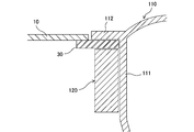
- FIG. 3 is a schematic partial sectional view showing a state in which the fan is attached to the fan attachment portion.
- FIG. 4 is a diagram for explaining a first step and a second step in the method for producing a sheet with a fan attachment portion of the first embodiment.
- FIG. 5 is a diagram for explaining a third step in the method for producing the sheet with the fan attachment portion.
- FIG. 6 is a schematic partial sectional view showing a state in which the fan is attached to the fan attachment portion in the modification of the first embodiment.
- FIG. 7A is a schematic rear view of a sheet with a fan mounting portion according to the second embodiment of the present invention
- FIG. 7B is a schematic partial sectional view in the direction of arrow BB of the sheet with a fan mounting portion. .
- FIG. 8 is a view for explaining a first step and a second step in the method for producing a sheet with a fan attachment portion of the second embodiment.
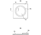
- FIG. 9A is a schematic rear view of a sheet with a fan attachment portion according to the third embodiment of the present invention
- FIG. 9B is a view when the sheet with a fan attachment portion is attached to a predetermined cloth part of an air-conditioning garment. It is a figure for demonstrating a state.
- FIG. 10A is a schematic rear view of a sheet with a fan mounting portion, which is a modification of the third embodiment
- FIG. 10B is a schematic partial cross-sectional view in the DD direction of the sheet with a fan mounting portion.
- FIG. 11 is a diagram showing a typical configuration of the seat with a fan mounting portion of the present invention.
- FIG. 12 is a schematic side view of a general work clothes.
- FIG. 1A is a schematic front view of a sheet with a fan mounting portion according to the first embodiment of the present invention
- FIG. 1B is a schematic rear view of the sheet with a fan mounting portion
- FIG. FIG. 6 is a schematic partial cross-sectional view in the direction of arrow AA of the seat with attachment portion.
- FIG. 2A is a schematic side view showing a state when a fan used in an air circulation mat, air conditioning clothing, or the like is inserted into the opening hole of the sheet with the fan mounting portion of the first embodiment
- FIG. Fig. 2 is a schematic side view of an annular locking member in the fan
- Fig. 2C is a schematic side view showing a state when the fan is attached to the fan attachment portion.
- FIG. 3 is a schematic partial sectional view showing a state in which the fan is attached to the fan attachment portion.
- the sheet 1 with a fan mounting portion of the first embodiment is used when air-conditioning clothing or the like is manufactured by a method using a self-seat method. For this reason, as the sheet-like member 10, what cut
- the material of the sheet-like member 10 is, for example, a normal woven fabric.
- the sheet-like member 10 has a front and back. That is, the surface located on the front side of the air-conditioning garment manufactured using the sheet 1 with the fan attachment portion is the surface of the sheet-like member 10, and the surface located on the back side of the air-conditioning garment is the back surface of the sheet-like member 10. Further, following the positional relationship between the front and back surfaces of the sheet-like member 10, in each part, the surface on the side having the same positional relationship as the surface of the sheet-like member 10 is the front surface, and The surface is also referred to as the back surface.
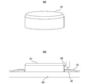
- the fan 100 used for air circulation mats and air-conditioning clothes will be briefly described.
- the fan 100 includes a fan main body 110 that houses a motor and a propeller, and an annular locking member 120 that is attached to the fan main body 110.
- the fan main body 110 includes a tubular portion 111 and a flange portion 112 that protrudes from the upper end of the tubular portion 111 in a direction substantially perpendicular to the side surface of the tubular portion 111.
- the outer shape of the cross section when the cylindrical portion 111 is cut by a plane perpendicular to the central axis is circular.
- the outer diameter F of the cylindrical part 111 is 64.5 mm.
- the locking member 120 is a dedicated tool for attaching the fan main body 110 to the fan attachment portion of the seat 1 with the fan attachment portion.
- Two locking claws 113 are provided on the cylindrical portion 111 of the fan main body 110.
- a projection (not shown) is provided on the inner surface of the locking member 120 to engage with each locking claw 113 and fix the locking member 120 to the outer surface of the cylindrical portion 111. .
- the locking member 120 can be easily attached to the fan main body 110 in a state of facing the flange portion 112 by inserting the locking member 120 outside the cylindrical portion 111 and engaging with the fan main body 110. Can do.
- the opening hole 20 in the sheet 1 with the fan attachment portion is for passing the cylindrical portion 111 of the fan 100 and is formed at a predetermined position of the sheet-like member 10.
- the shape of the opening hole 20 is circular.
- the diameter of the opening hole 20 is substantially the same as or larger than the outer diameter F of the cylindrical portion 111.
- the opening hole 20 having substantially the same diameter as the outer diameter F of the cylindrical portion 111 is formed in the sheet-like member.
- the reinforcing member 30 is a flat annular member having an opening having substantially the same shape as the outer edge of the cylindrical portion 111 of the fan 100.
- the reinforcing member 30 has an annular shape, and has an inner diameter (diameter of the opening) that is substantially the same as the outer diameter F of the cylindrical portion 111. . Therefore, the inner diameter of the reinforcing member 30 and the diameter of the opening hole 20 are substantially the same.
- the material of the reinforcing member 30 a material that can be washed and does not have much stretchability and can be sewn is used. Specifically, any material of plastic, resin-impregnated cloth, artificial leather, and non-stretchable rubber can be used.
- the reinforcing member 30 is made of polypropylene and has a thickness of 0.5 mm, an inner diameter of 65 mm, an outer diameter of 73 mm, and a width of 4 mm.
- the reinforcing member 30 can be easily manufactured with high accuracy by punching a polypropylene sheet.
- the reinforcing member 30 is opaque.
- the reinforcing member 30 is fixed to the back surface of the sheet-like member 10 and to the end portion of the sheet-like member 10 around the opening hole 20. That is, the surface of the reinforcing member 30 is fixed to the end portion of the sheet-like member 10 around the opening hole 20. Specifically, the reinforcing member 30 is fixed to the sheet-like member 10 by stitching the reinforcing member 30 and the end of the sheet-like member 10 around the opening hole 20 with a thread 40.
- FIG. 1 (a), (b) the seam 41 formed by this sewing operation
- the diameter of the opening hole 20 is substantially the same as or larger than the inner diameter (diameter of the opening) of the reinforcing member 30.
- the outer diameter of the reinforcing member 30 must be larger than the diameter of the opening hole 20. This is because it is necessary to attach the reinforcing member 30 to the end portion of the sheet-like member 10 around the opening hole 20.
- the opening member 20 having a diameter substantially the same as the inner diameter of the reinforcing member 30 is formed in the sheet-like member 10.
- the doubled portions are overlapped to overlap each other.
- the cloth reinforcing process includes a process for ensuring that the two members after stitching have sufficient strength when two members, at least one of which is made of cloth, are sewn, and a thread for the cloth members. It means both processing to prevent fraying.
- an anchor is provided on the back surface of the sheet-like member 10 and on the portion X of the sheet-like member 10 around the opening hole 20.
- the fabric is reinforced using the effect. Specifically, by welding a predetermined resin to the portion X of the sheet-like member 10 around the opening hole 20, the strength of the portion X of the sheet-like member 10 is increased and the fraying of the yarn is prevented. Yes. And after aligning the position of the inner edge of the reinforcement member 30 and the opening hole 20 correctly, as shown to Fig.1 (a), (b), the sheet-like member 10 around the reinforcement member 30 and the opening hole 20 is shown. The ends are integrated with a thread 40 in a circular shape.
- the tubular portion 111 of the fan main body 110 is inserted into the opening of the reinforcing member 30, and as shown in FIG.
- the lower surface of the flange 112 is in contact with the edge of the sheet-like member 10 around the opening hole 20.
- the locking member 120 is inserting to the outside of the cylindrical portion 111, as shown in FIG. 3, the end portion of the sheet-like member 10 and the end portion of the reinforcing member 30 around the opening hole 20 are connected to the flange portion.
- the fan 100 is attached to the fan attachment portion.
- the reinforcing member 30 and the locking member 120 are in direct contact with each other, and the inner side surface 31 of the reinforcing member 30 is in direct contact with the outer side surface of the tubular portion 111. Yes.
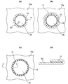
- a circular reinforcing treatment sheet 60 as shown in FIG. 4A is prepared.
- the reinforcing treatment sheet 60 is made of polypropylene and has a diameter of 75 mm and a thickness of about 0.2 mm.
- the reinforcing treatment sheet 60 is disposed under the sheet-like member 10.
- the horn 70 for an ultrasonic welder having a ring-shaped pressing surface is set so that its own central axis coincides with the central axis of the reinforcing treatment sheet 60. And press against the sheet-like member 10.
- the inner diameter of the horn 70 for an ultrasonic welder is smaller than the outer diameter F of the cylindrical portion 111.
- the outer diameter of the horn 70 is desirably larger than the diameter of the reinforcing treatment sheet 60.
- the polypropylene resin is welded to a predetermined portion of the back surface of the sheet-like member 10, thereby increasing the strength of the portion.
- FIG. 4C when the sheet-like member 10 is viewed from the back side, the ring-shaped portion X to which the polypropylene resin has been welded, that is, subjected to the reinforcing treatment, is indicated by hatching.
- the opening hole 20 is opened in the sheet-like member 10 by cutting X. Thereby, the width of the portion X is narrowed.
- the polypropylene resin is welded to the reinforced portion X, the yarn located on the cut surface is not frayed.
- the reinforcing member 30 and the sheet-like member 10 are stitched together using a sewing machine.
- a predetermined sewing jig is used.
- the sewing jig 81 is formed in a substantially cylindrical shape as shown in FIG.
- the outer diameter of the sewing jig 81 is substantially the same as the inner diameter of the reinforcing member 30.
- the upper part of the sewing jig 81 is chamfered.
- a sewing jig 81 is placed on the table 82 of the sewing machine.
- the reinforcing member 30 is inserted into the sewing jig 81.
- the sheet-like member 10 is inserted into the sewing jig 81 with the surface on which the polypropylene resin is welded down in the first step.
- the reinforcing member 30 and the sheet-like member 10 are overlapped.
- the reinforcing member 30 and the sheet-like member 10 are attached using the sewing machine in a state where the presser column 83 of the sewing machine is applied to the side wall of the sewing jig 81 at a right angle. Sew in a circle.
- the sheet 1 with a fan attachment portion of the first embodiment is produced.
- the cloth is reinforced by welding the resin to the sheet-like member 10
- a commercially available fray-fastening agent is applied to the sheet-like member 10.
- the cloth may be reinforced.
- the sheet-like member 10 is laminated, like a material used for rainwear, has no fraying, and has sufficient strength against stitching, etc.
- the first step of applying a cloth reinforcing process to a predetermined portion of the sheet-like member 10 can be omitted.
- the reinforcing member is fixed to the end of the sheet-like member around the opening hole, so that when the sheet with the fan mounting portion is manufactured, , It is not necessary to fold the sheet-like member, put a reinforcing member into the folded sheet-like member, and apply a backing cloth to the sheet-like member at that part, so the fan mounting part can be easily attached to the sheet-like member Can be produced.
- the end of the sheet-like member around the opening hole can be reinforced by the non-stretchable reinforcing member so that the end can be reinforced, so that even between the fan and the reinforcing member or the fan Even if a strong force is applied between the sheet mounting member and the sheet-like member, the fan does not easily come off from the seat mounting portion.
- the surfaces of the reinforcing member among the surfaces of the reinforcing member, the surfaces other than one surface fixed to the end of the sheet-like member are exposed without being covered with the sheet-like member, so that the inner surface of the fan mounting portion is the reinforcing member. Therefore, if the shape and size of the reinforcing member are manufactured with high accuracy, the shape and size of the fan mounting portion can be formed with high accuracy.
- the entire surface of the reinforcing member is completely covered with the sheet-like member, so that when the fan is removed from the fan mounting portion, the reinforcing member is externally attached. Since it cannot be seen, the appearance of air-conditioning clothes etc. will not deteriorate. Furthermore, the portion of the sheet-like member on the back surface of the sheet-like member around the opening hole is subjected to a fabric reinforcement process using an anchor effect, thereby effectively preventing fraying of the yarn in the portion. be able to. Further, the reinforcing member can be firmly attached to the sheet-like member by stitching the reinforcing member and the portion of the sheet-like member subjected to the reinforcing treatment.
- FIG. 6 is a schematic partial sectional view showing a state in which the fan is attached to the fan attachment portion in the modification of the first embodiment.
- FIG. 6 only a part of the upper surface (surface) of the reinforcing member 30 is covered with the sheet-like member 10, and when the fan 100 is attached to the fan attachment portion, the opening is opened. Only the end of the reinforcing member 30 around the hole 20 is sandwiched between the lower surface of the flange portion 112 and the upper surface of the locking member 120.
- FIG. 7A is a schematic rear view of a sheet with a fan mounting portion according to the second embodiment of the present invention
- FIG. 7B is a schematic partial sectional view in the direction of arrow BB of the sheet with a fan mounting portion.
- components having the same functions as those in the first embodiment are denoted by the same reference numerals, and detailed description thereof is omitted.
- the sheet 1a with a fan mounting portion of the second embodiment includes a sheet-like member 10a, an opening hole 20, and a flat annular reinforcing member (reinforcing means) 30a having no elasticity.
- This sheet 1a with a fan attachment part is used when manufacturing air-conditioning clothes etc. mainly by the method by a self-seat system.
- the difference between the sheet 1a with a fan attachment portion of the second embodiment and the sheet 1 with a fan attachment portion of the first embodiment is performed by a general sewing operation as a cloth reinforcement process on the sheet-like member 10a.
- a fray-fastening point is adopted, and a transparent member is used as the reinforcing member 30a.
- Other configurations are the same as those of the first embodiment.
- a plurality of cuts 13 are made at the end of the sheet-like member 10 a around the opening hole 20, and the sheet-like member 10 a into which the cuts 13 are put.
- the part is folded back.
- the portion of the sheet-like member 10a in which the cut 13 is made is also referred to as a “cut portion 14”.
- each notch part 14 and the part of the sheet-like member 10a which overlaps with it are adhere
- surroundings of the opening hole 20 is made double, the strength is raised, and the fraying of a thread
- the reinforcing member 30 a is the back surface of the sheet-like member 10 a, and is provided at the end portion (double portion) of the sheet-like member 10 a around the opening hole 20. It is fixed.
- FIG. 8 is a diagram for explaining the first step and the second step in the method for producing the sheet 1a with a fan attachment portion of the second embodiment.
- FIG. 8 (d) is a schematic cross-sectional view in the direction of the arrow CC in FIG. 8 (c).
- an opening hole 20 is opened at a predetermined location of the sheet-like member 10a, and the end of the sheet-like member 10a around the opening hole 20 is formed.
- a number of cuts 13 are made in the part.
- a circular hole having a diameter of 55 mm is formed as the opening hole 20.
- a large number of the cuts 13 are radially entered into the ring-shaped portion of the sheet-like member 10 surrounded by the circle C1 having a diameter of 55 mm and the circle C2 having a diameter of 65 mm, which are the edges of the opening hole 20.
- This ring-shaped portion is composed of a large number of cut portions 14 divided by cuts 13.
- the above numerical value of 65 mm which is the length of the cut 13 to be inserted into the sheet-like member 10 is a numerical value corresponding to the outer diameter 64.5 mm of the cylindrical portion 111 of the fan 100.
- the above numerical value does not define the exact length of the cut 13.
- numerical values described for the dimensions and the like of the sheet-like member 10 do not prescribe strict values.
- a ring-shaped bonding sheet 15 is prepared.
- the bonding sheet 15 is made of polypropylene, and has an inner diameter of 65 mm, an outer diameter of 75 mm, and a thickness of 0.2 mm.
- the sheet-like member 10a is placed on the ironing board with its back surface facing up.
- attachment is arrange
- FIG. 8C the cut portion 14 in the sheet-like member 10 a is folded back onto the adhesive sheet 15.
- each notch portion 14 is folded and pressed with the tip of the iron, the folds can be creased, so that each notch portion 14 returns to its original state. Can be reliably prevented.
- the ultrasonic welder horn 70 used in the first embodiment is pressed onto the sheet-like member 10a corresponding to the folded cut portion 14. Then, when the horn 70 is ultrasonically vibrated, the adhesive sheet 15 is melted and overlapped with each cut portion 14 by the molten adhesive sheet (polypropylene resin) as shown in FIG. The sheet-like member 10a is adhered. As described above, since the end portion of the sheet-like member 10a around the opening hole 20 is doubled, the strength of the end portion can be increased and the fraying of the yarn can be prevented. Moreover, since each notch part 14 was turned back in the 2nd process, the diameter of the opening hole 20 is expanded from 55 mm to 65 mm.
- the polypropylene adhesive sheet 15 is used as an adhesive for adhering the cut portion 14 to the portion of the sheet-like member 10a overlapping therewith. Therefore, the adhesive sheet is not limited to the polypropylene adhesive sheet 15, and various materials can be used as long as the sheet exhibits an adhesive effect.
- the bonding method is not limited to the method using ultrasonic welding, and a bonding method according to the material used, such as heat welding using a heater, can be used.
- a sewing operation is performed between the reinforcing member 30a and the sheet-like member 10 using a sewing machine.
- the suturing operation in the third step is the same as the third step in the first embodiment.
- Fig.7 (a) the circular shaped seam 41 formed by this sewing operation
- the sheet with a fan mounting portion of the second embodiment exhibits substantially the same operations and effects as the sheet with a fan mounting portion of the first embodiment. However, when producing the sheet with a fan mounting portion of the second embodiment, it is necessary to perform an operation of folding and bonding the end of the sheet-like member around the opening hole. Comparing the sheet with the fan mounting part of the embodiment and the sheet with the fan mounting part of the first embodiment, it can be said that the latter can be produced more easily.
- a transparent member is used as the reinforcing member, but technically, it is desirable to use an opaque member as the reinforcing member. This is because when the reinforcing member is transparent, when the fan mounting portion is viewed from the back side of the air-conditioning garment, the state where the cut portion is folded back is visible, and the appearance is not good.
- a sheet 1b with a fan attachment portion of the third embodiment includes a sheet-like member 10b, an opening hole 20, a flat annular reinforcing member (reinforcing means) 30 that does not have elasticity.
- the difference between the sheet 1b with a fan attachment portion of the third embodiment and the sheet 1 with a fan attachment portion of the first embodiment is that the sheet 1b with a fan attachment portion manufactures air-conditioning clothing and the like by a method using another sheet method. This is the point used.
- the sheet 1b with a fan attachment portion manufactures air-conditioning clothing and the like by a method using another sheet method. This is the point used.
- the sheet-like member 10 since the cloth member used for the air-conditioning clothing itself is used as the sheet-like member 10, for example, the size of the sheet-like member 10 is considerably larger than the size of the fan mounting portion.
- the sheet-like member 10b as shown in FIG. 9 (a), a member formed in a square shape that is slightly larger than the size of the fan mounting
- seat 1b with a fan attachment part is used for manufacture of the air-conditioning clothing etc. by the method by another sheet system, it is a sheet
- the sheet-like member 10b is placed at a predetermined position of the cloth part of the air-conditioning garment corresponding to the attachment part of the fan. Make a square hole with a size slightly smaller than the size of. Thereafter, as shown in FIG. 9B, the sheet 1b with the fan attachment portion is attached to the cloth part 200 by sewing the end of the sheet-like member 10b to the portion of the cloth part 200 around the hole.
- FIG.9 (b) the square-shaped seam 42 formed by this sewing operation
- the sheet with the fan mounting portion of the third embodiment exhibits substantially the same operations and effects as the sheet with the fan mounting portion of the first embodiment.
- the cloth parts 200 are stitched together at a position just beside the general work clothes shown in FIG. 12, and in the self-seat method, a fan is placed at the position beside the air-conditioning garment. It is difficult to produce the mounting portion.
- the sheet 1b with the fan attachment portion can be easily attached across the adjacent fabric parts 200. Therefore, when the sheet with the fan mounting portion of the third embodiment is used, the fan can be provided at a position directly beside the air-conditioning clothing. Thereby, for example, it can be avoided that the fan gets in the way when getting on an automobile or the like.
- the shape of the sheet-like member is not limited to the quadrangular shape, and may be a triangular shape, a circular shape, or the like.
- FIG. 10A is a schematic rear view of a sheet with a fan mounting portion, which is a modification of the third embodiment
- FIG. 10B is a schematic partial cross-sectional view in the DD direction of the sheet with a fan mounting portion. .
- a sheet 1c with a fan attachment portion which is a modification of the third embodiment, includes a sheet-like member 10c, an opening hole 20, and a flat annular reinforcing member (reinforcing means) 30c that is not stretchable.
- the material of the sheet-like member 10c and the material of the reinforcing member 30c are the same, and the sheet-like member 10c and the reinforcing member 30c are integrally molded. It can be considered that the surface of the reinforcing member 30c is also fixed to the end portion of the sheet-like member 10c around the opening hole 20 in the fan-attached seat 1c.
- plastic can be used as the material of the sheet-like member 10c and the material of the reinforcing member 30c.
- an integrally molded product of the sheet-like member 10c and the reinforcing member 30c can be easily produced by a method such as injection molding.
- the cylindrical portion is perpendicular to the central axis.
- the outer shape of the cross section when cut by a plane may be a square, for example.
- the shape of the opening hole in the fan mounting portion is changed from a circular shape to a shape corresponding to the outer shape of the cylindrical portion, and the reinforcing member and the sewing jig have a shape corresponding to the outer shape of the cylindrical portion. What is necessary is just to use.
- the protrusion protrudes in a direction substantially perpendicular to the tubular portion and the side surface of the tubular portion.
- the fan comprises a fan body having a protruding portion provided on the cylindrical portion and a locking member that is inserted into the outside of the cylindrical portion and is mounted on the fan main body in a state of facing the protruding portion.
- Any fan can be attached to the seat with a fan attachment portion of the present invention.
- the fan may be configured such that the back surface of the reinforcing member and the protruding portion are in direct contact with each other when the fan is attached.
- the reinforcing member and the sheet-like member are stitched in a circle around the center of the reinforcing member.
- the reinforcing member and the sheet-like member are connected to the inner edge of the reinforcing member. You may make it sew
- the sheet-like member has moisture permeability because of its character.
- an inexpensive material for example, a plastic sheet such as a vinyl sheet, can be used as a material for the sheet-like member depending on the purpose of use of the air-conditioning clothing.
- the reinforcing member is fixed to the sheet-like member by stitching the reinforcing member and the end of the sheet-like member around the opening hole.
- the reinforcing member may be fixed to the sheet-like member by welding the reinforcing member and the end of the sheet-like member around the opening hole.
- FIG. 11 shows a typical configuration of the seat with a fan mounting portion of the present invention.
- FIGS. 11 (a) to 11 (d) are configuration examples of the seat with a fan mounting portion used when manufacturing air-conditioning clothing and the like by the method of the self seat method
- FIGS. 11 (e) to 11 (g) are other examples.
- 11 (e) to 11 (g) show a state in which the sheet with the fan attachment portion is attached to a cloth part such as an air-conditioning suit.
- the surfaces other than the surface fixed to the end of the sheet-like member among the surfaces of the reinforcing member are exposed without being covered with the sheet-like member.
- the exposed surface of the front and back surfaces of the reinforcing member may be covered by some method. Even in this case, the inner side surface of the reinforcing member is exposed, and it does not change that the inner side surface of the reinforcing member comes into direct contact with the outer side surface of the cylindrical portion of the fan when the fan is attached.
- the sheet with a fan mounting portion shown in FIG. 11 (a) is that in the first embodiment.
- the entire surface of the reinforcing member 30 is covered with the sheet-like member 10, and the reinforcing member 30 cannot be seen from the front side of the sheet-like member 10. Further, the reinforcing member 30 and the sheet-like member 10 are stitched together with a thread 40.
- the reinforcing member 30 and the sheet-like member 10 are made of a material that can be welded.
- the reinforcing member 30 is fixed to the sheet-like member 10 by welding the reinforcing member 30 and the sheet-like member 10.
- the reinforcing member 30 is fixed to the surface of the sheet-like member 10 and to the end of the sheet-like member 10 around the opening hole. That is, the back surface of the reinforcing member 30 is fixed to the end portion of the sheet-like member 10 around the opening hole. Thereby, the reinforcing member 30 can be made conspicuous and used as a part of the design.
- the sheet with the fan mounting portion shown in FIG. 11 (d) is the one shown in FIG. Only a part of the surface of the reinforcing member 30 is covered with the sheet-like member 10, and a part of the reinforcing member 30 can be seen from the front side of the sheet-like member 10.
- the sheet with a fan attachment portion shown in FIG. 11 (e) is that in the third embodiment.
- the fan-attached sheet 1b is stitched to the cloth part 200 with a thread 40.
- the sheet with a fan attachment portion shown in FIG. 11 (f) is a modification of the third embodiment.
- the material of the sheet-like member 10c and the material of the reinforcing member 30c are the same, and the sheet-like member 10c and the reinforcing member 30c are integrally molded. Further, the sheet 1c with a fan attachment portion is stitched to the cloth part 200 with a thread 40.
- FIG. 11 Each configuration example shown in FIG. 11 is a representative example, and the configuration of the seat with a fan mounting portion of the present invention is not limited to these.
- the sheet with a fan mounting portion of the present invention As described above, in the sheet with a fan mounting portion of the present invention, one of the front surface and the back surface of the reinforcing means is fixed to the end portion of the sheet-like member around the opening hole. For this reason, when producing a fan mounting portion for mounting a fan on a sheet-like member, the sheet-like member is folded back as in the prior art, and a reinforcing means is inserted into the folded-up sheet-like member and the sheet of that portion is placed. Since it is not necessary to apply the backing cloth to the sheet-like member, the fan mounting portion can be easily produced on the sheet-like member.
- the end portion of the sheet-like member around the opening hole is not expanded or contracted by the non-stretchable reinforcing means, the end portion can be reinforced, so that even between the fan and the reinforcing means, or the fan Even if a strong force is applied between the fan and the sheet-like member, the fan is not easily detached from the fan mounting portion. Therefore, the present invention is suitable for use in air circulation mats and air-conditioning clothes.
Landscapes
- Engineering & Computer Science (AREA)
- Mechanical Engineering (AREA)
- General Engineering & Computer Science (AREA)
- Structures Of Non-Positive Displacement Pumps (AREA)
- Professional, Industrial, Or Sporting Protective Garments (AREA)
Abstract
Description
まず、本発明の第一実施形態について図面を参照して説明する。図1(a)は本発明の第一実施形態であるファン取付部付きシートの概略表面図、図1(b)はそのファン取付部付きシートの概略裏面図、図1(c)はそのファン取付部付きシートのA-A矢視方向概略部分断面図である。図2(a)は空気流通式マットや空調服等に使用されるファンを第一実施形態のファン取付部付きシートの開口孔に差し込んだときの様子を示す概略側面図、図2(b)はそのファンにおける環状の係止部材の概略側面図、図2(c)はそのファンをファン取付部に取り付けたときの様子を示す概略側面図である。図3はファンがファン取付部に取り付けられている様子を示す概略部分断面図である。
第一実施形態のファン取付部付きシート1の作製方法は、シート状部材10の所定部分に布の強化処理を施す第一工程と、シート状部材10に開口孔20を形成する第二工程と、補強部材30とシート状部材10とを縫合する第三工程とからなる。図4は第一実施形態のファン取付部付きシート1の作製方法における第一工程及び第二工程を説明するための図、図5はそのファン取付部付きシート1の作製方法における第三工程を説明するための図である。
次に、本発明の第二実施形態であるファン取付部付きシートについて説明する。図7(a)は本発明の第二実施形態であるファン取付部付きシートの概略裏面図、図7(b)はそのファン取付部付きシートのB-B矢視方向概略部分断面図である。尚、第二実施形態において、第一実施形態のものと同一の機能を有するものには、同一の符号を付すことにより、その詳細な説明を省略する。
第二実施形態のファン取付部付きシート1aの作製方法は、シート状部材10aに開口孔20と切り込み13を形成する第一工程と、シート状部材10aの所定部分に布の強化処理を施す第二工程と、補強部材30aとシート状部材10aとを縫合する第三工程とからなる。図8は第二実施形態のファン取付部付きシート1aの作製方法における第一工程及び第二工程を説明するための図である。ここで、図8(d)は図8(c)におけるC-C矢視方向概略断面図である。
次に、本発明の第三実施形態であるファン取付部付きシートについて説明する。図9(a)は本発明の第三実施形態であるファン取付部付きシートの概略裏面図、図9(b)はそのファン取付部付きシートを空調服の所定の布パーツに取り付けたときの状態を説明するための図である。ここで、図9(b)は、空調服の裏側から見たときの状態を示している。尚、第三実施形態において、第一実施形態のものと同一の機能を有するものには、同一の符号を付すことにより、その詳細な説明を省略する。
次に、第三実施形態の変形例について説明する。図10(a)は第三実施形態の変形例であるファン取付部付きシートの概略裏面図、図10(b)はそのファン取付部付きシートのD-D矢視方向概略部分断面図である。
尚、本発明は上記の各実施形態に限定されるものではなく、その要旨の範囲内において種々の変形が可能である。
10,10a,10b,10c シート状部材
13 切り込み
14 切込部
15 接着用シート
20 開口孔
30,30a,30c 補強部材(補強手段)
31 内側面
40 糸
41,42 縫い目
60 強化処理用シート
70 超音波溶着機用のホーン
81 縫製用ジグ
82 ミシンのテーブル
83 ミシンの押さえ金の柱部
100 ファン
110 ファン本体
111 筒状部
112 フランジ部(突出部)
113 係止爪
120 係止部材
200 布パーツ
210 縫い目
Claims (11)
- 筒状部とその筒状部の側面と略垂直な方向に突出するように前記筒状部に設けられた突出部とを有するファン本体と、前記筒状部の外側に差し込んで前記突出部と対向する状態で前記ファン本体に装着される係止部材とを備えるファンを取り付けるためのファン取付部付きシートであって、
前記ファンの前記筒状部を通すための開口孔が形成されたシート状部材と、
前記ファンの前記筒状部の外縁の形状と略同じ形状の開口部を有し、表面及び裏面のうち一方の面が前記開口孔の周囲における前記シート状部材の端部に固着され、内側面が露出している伸縮性のない扁平な環状の補強手段と、
を備え、
前記筒状部を前記補強手段の前記開口部に挿入すると共に前記係止部材を前記ファン本体に装着し、前記開口孔の周囲における前記シート状部材の端部及び前記補強手段の端部のうち少なくも前記補強手段の端部を前記突出部と前記係止部材との間で挟み込むことにより、前記ファンが取り付けられることを特徴とするファン取付部付きシート。 - 前記ファンが取り付けられたときに、前記補強手段の裏面と前記係止部材又は前記突出部とが直接接することを特徴とする請求項1記載のファン取付部付きシート。
- 前記補強手段は、洗濯可能なものであって、プラスチック、樹脂含浸布、人工皮革、伸縮性のないゴムのいずれかの素材で作製されたものであることを特徴とする請求項1又は2記載のファン取付部付きシート。
- 前記補強手段は縫合可能な素材で作製されており、前記補強手段と前記開口孔の周囲における前記シート状部材の端部とを縫合することにより前記補強手段が前記シート状部材に固着されていることを特徴とする請求項1、2又は3記載のファン取付部付きシート。
- 前記補強手段と前記シート状部材とは溶着可能な素材で作製されており、前記補強手段と前記開口孔の周囲における前記シート状部材の端部とを溶着することにより前記補強手段が前記シート状部材に固着されていることを特徴とする請求項1又は2記載のファン取付部付きシート。
- 前記シート状部材の素材と前記補強手段の素材とが同じであることを特徴とする請求項1、2又は3記載のファン取付部付きシート。
- 前記補強手段と前記シート状部材とは一体的に成型されていることを特徴とする請求項6記載のファン取付部付きシート。
- 前記シート状部材は織布からなり、前記開口孔の周囲における前記シート状部材の端部にはほつれ留めが施され、前記補強手段と前記開口孔の周囲における前記シート部の端部とを縫合することにより前記補強手段が前記シート状部材に固着されていることを特徴とする請求項1又は2記載のファン取付部付きシート。
- 前記開口孔の大きさは前記補強手段の前記開口部の大きさと略同じであり、前記補強手段の表面の全体が前記開口孔の周囲における前記シート状部材の端部に接していることを特徴とする請求項1乃至8のいずれか一項記載のファン取付部付きシート。
- 前記シート状部材は縫合可能な素材で作製されていることを特徴とする請求項1、2、3、5、6、7記載のファン取付部付きシート。
- 前記補強手段は不透明なものであることを特徴とする請求項1乃至10のいずれか一項記載のファン取付部付きシート。
Priority Applications (8)
| Application Number | Priority Date | Filing Date | Title |
|---|---|---|---|
| EP14886000.0A EP3121452B1 (en) | 2014-03-18 | 2014-03-18 | Sheet having fan-mounting part |
| PCT/JP2014/057357 WO2015140926A1 (ja) | 2014-03-18 | 2014-03-18 | ファン取付部付きシート |
| US15/122,921 US10731665B2 (en) | 2014-03-18 | 2014-03-18 | Sheet having fan-mounting part |
| JP2016508371A JP6412108B2 (ja) | 2014-03-18 | 2014-03-18 | ファン取付部付きシート、空調衣服の服本体及び空調衣服 |
| ES14886000T ES2787175T3 (es) | 2014-03-18 | 2014-03-18 | Lámina que tiene un elemento de montaje de un ventilador |
| CN201480077240.XA CN106104008B (zh) | 2014-03-18 | 2014-03-18 | 带风扇安装部的片材 |
| CN201911070345.3A CN110725810B (zh) | 2014-03-18 | 2014-03-18 | 带风扇安装部的片材 |
| US16/922,011 US11572895B2 (en) | 2014-03-18 | 2020-07-07 | Sheet having fan-mounting part |
Applications Claiming Priority (1)
| Application Number | Priority Date | Filing Date | Title |
|---|---|---|---|
| PCT/JP2014/057357 WO2015140926A1 (ja) | 2014-03-18 | 2014-03-18 | ファン取付部付きシート |
Related Child Applications (2)
| Application Number | Title | Priority Date | Filing Date |
|---|---|---|---|
| US15/122,921 A-371-Of-International US10731665B2 (en) | 2014-03-18 | 2014-03-18 | Sheet having fan-mounting part |
| US16/922,011 Continuation US11572895B2 (en) | 2014-03-18 | 2020-07-07 | Sheet having fan-mounting part |
Publications (1)
| Publication Number | Publication Date |
|---|---|
| WO2015140926A1 true WO2015140926A1 (ja) | 2015-09-24 |
Family
ID=54143939
Family Applications (1)
| Application Number | Title | Priority Date | Filing Date |
|---|---|---|---|
| PCT/JP2014/057357 WO2015140926A1 (ja) | 2014-03-18 | 2014-03-18 | ファン取付部付きシート |
Country Status (6)
| Country | Link |
|---|---|
| US (2) | US10731665B2 (ja) |
| EP (1) | EP3121452B1 (ja) |
| JP (1) | JP6412108B2 (ja) |
| CN (2) | CN106104008B (ja) |
| ES (1) | ES2787175T3 (ja) |
| WO (1) | WO2015140926A1 (ja) |
Cited By (17)
| Publication number | Priority date | Publication date | Assignee | Title |
|---|---|---|---|---|
| JP2017057547A (ja) * | 2015-09-16 | 2017-03-23 | 株式会社ブレイン | 衣服用ファン取付用ワッペン及びこれを具備するファン付き衣服 |
| JP6108327B1 (ja) * | 2016-07-22 | 2017-04-05 | 株式会社サンエス | ファン取付部の作製方法 |
| JP6159047B1 (ja) * | 2017-03-29 | 2017-07-05 | 株式会社サンエス | ファン取付部の作製方法 |
| WO2017130406A1 (ja) * | 2016-01-29 | 2017-08-03 | 株式会社セフト研究所 | 取付孔加工治具及び取付孔加工治具を用いた取付孔製造方法 |
| JP6226214B1 (ja) * | 2017-04-04 | 2017-11-08 | 株式会社サンエス | 冷却衣服 |
| JP6230037B1 (ja) * | 2016-10-17 | 2017-11-15 | 株式会社チロル | 縫製方法 |
| JP2018012906A (ja) * | 2017-02-15 | 2018-01-25 | 株式会社サンエス | ファン取付部の作製方法 |
| JP2018012907A (ja) * | 2017-02-16 | 2018-01-25 | 株式会社サンエス | 冷却衣服 |
| JP2018066100A (ja) * | 2017-09-07 | 2018-04-26 | 株式会社チロル | 縫製方法 |
| JP6393866B1 (ja) * | 2018-03-01 | 2018-09-19 | エンレイ リン | 服内環境冷却装置 |
| JP2019052396A (ja) * | 2017-09-15 | 2019-04-04 | ミドリ安全株式会社 | 衣服及び衣服の製造方法 |
| JP2019189982A (ja) * | 2018-04-26 | 2019-10-31 | 株式会社マキタ | 衣服 |
| JP2020067058A (ja) * | 2018-10-26 | 2020-04-30 | ミドリ安全株式会社 | 衣服用ファン |
| JP2020122241A (ja) * | 2019-01-31 | 2020-08-13 | ライターム株式会社 | 空調衣服の製造方法 |
| JP2021031789A (ja) * | 2019-08-21 | 2021-03-01 | 誠一 古後 | 送風装置取付部、送風装置取付部の作製方法、空調服、及び縫製部品 |
| JP2023010300A (ja) * | 2021-07-09 | 2023-01-20 | 株式会社金田工業 | 作業用頭巾 |
| US11571028B2 (en) | 2016-03-09 | 2023-02-07 | Sft Laboratory Co., Ltd. | Electric component mounting unit for air-conditioned garment, and air-conditioned garment |
Families Citing this family (3)
| Publication number | Priority date | Publication date | Assignee | Title |
|---|---|---|---|---|
| JP2020125561A (ja) * | 2019-02-05 | 2020-08-20 | 株式会社デサント | 衣料 |
| CN110985447A (zh) * | 2019-12-02 | 2020-04-10 | 徐州华扬矿山设备制造有限公司 | 一种便于维修保养的环保风机 |
| JP7339228B2 (ja) * | 2020-11-10 | 2023-09-05 | トヨタ自動車株式会社 | 空調衣服 |
Citations (3)
| Publication number | Priority date | Publication date | Assignee | Title |
|---|---|---|---|---|
| JPH0633756U (ja) * | 1992-10-12 | 1994-05-06 | 東洋ゴム工業株式会社 | ベントホールを備えた車両用エアバッグ |
| JPH09156440A (ja) * | 1995-12-11 | 1997-06-17 | Bridgestone Corp | エアバッグの製造方法 |
| WO2006090677A1 (ja) * | 2005-02-25 | 2006-08-31 | Seft Development Laboratory Co., Ltd. | 空調衣服、及び空調衣服におけるファン取付用孔の形成方法 |
Family Cites Families (14)
| Publication number | Priority date | Publication date | Assignee | Title |
|---|---|---|---|---|
| US2826758A (en) * | 1955-12-15 | 1958-03-18 | Kahn Alexander | Ventilated clothing and apparatus |
| JPH11324531A (ja) * | 1998-05-19 | 1999-11-26 | Tachikawa Blind Mfg Co Ltd | ロールブラインドのスクリーン、ロールブラインド及びロールブラインドのスクリーン製造方法 |
| US6692226B1 (en) | 2002-05-17 | 2004-02-17 | Tsung-Hsien Cheng | Vibration-proof fastener for a radiator |
| CN1627904A (zh) * | 2002-06-07 | 2005-06-15 | 株式会社斯福特开发研究所 | 冷却衣服 |
| EP1552759A4 (en) * | 2002-07-10 | 2007-08-15 | Seft Dev Lab Co Ltd | CLOTHES NOW BODY AT FRESH |
| JP4399765B2 (ja) * | 2003-06-26 | 2010-01-20 | 株式会社セフト研究所 | ファン露出型空調服用のファン取付装置及びファン露出型空調服用の送風装置 |
| JP4329118B2 (ja) | 2003-08-01 | 2009-09-09 | 株式会社セフト研究所 | 冷却衣服 |
| JPWO2006009108A1 (ja) * | 2004-07-21 | 2008-05-01 | 株式会社セフト研究所 | 空調衣服 |
| DE102006060990B4 (de) * | 2006-12-20 | 2010-01-07 | Entrak Energie- Und Antriebstechnik Gmbh & Co. Kg | Kleidungsstück zur Personenklimatisierung |
| CN201911317U (zh) * | 2010-12-15 | 2011-08-03 | 许文强 | 带有太阳能风扇的裤子 |
| CN202262453U (zh) * | 2011-09-21 | 2012-06-06 | 闫增力 | 一种排风工作服 |
| WO2015145666A1 (ja) * | 2014-03-27 | 2015-10-01 | 株式会社セフト研究所 | 空調服 |
| US20160270457A1 (en) * | 2015-03-20 | 2016-09-22 | Chien-Chou Chen | Clothes structure with temperature falling device |
| US20160286971A1 (en) * | 2015-03-30 | 2016-10-06 | Yucheng Pan | Flatus filtering system with forced air circulation for seats and beds and as wearables |
-
2014
- 2014-03-18 WO PCT/JP2014/057357 patent/WO2015140926A1/ja active Application Filing
- 2014-03-18 US US15/122,921 patent/US10731665B2/en active Active
- 2014-03-18 ES ES14886000T patent/ES2787175T3/es active Active
- 2014-03-18 JP JP2016508371A patent/JP6412108B2/ja active Active
- 2014-03-18 CN CN201480077240.XA patent/CN106104008B/zh active Active
- 2014-03-18 CN CN201911070345.3A patent/CN110725810B/zh active Active
- 2014-03-18 EP EP14886000.0A patent/EP3121452B1/en active Active
-
2020
- 2020-07-07 US US16/922,011 patent/US11572895B2/en active Active
Patent Citations (3)
| Publication number | Priority date | Publication date | Assignee | Title |
|---|---|---|---|---|
| JPH0633756U (ja) * | 1992-10-12 | 1994-05-06 | 東洋ゴム工業株式会社 | ベントホールを備えた車両用エアバッグ |
| JPH09156440A (ja) * | 1995-12-11 | 1997-06-17 | Bridgestone Corp | エアバッグの製造方法 |
| WO2006090677A1 (ja) * | 2005-02-25 | 2006-08-31 | Seft Development Laboratory Co., Ltd. | 空調衣服、及び空調衣服におけるファン取付用孔の形成方法 |
Non-Patent Citations (1)
| Title |
|---|
| See also references of EP3121452A4 * |
Cited By (26)
| Publication number | Priority date | Publication date | Assignee | Title |
|---|---|---|---|---|
| JP2017057547A (ja) * | 2015-09-16 | 2017-03-23 | 株式会社ブレイン | 衣服用ファン取付用ワッペン及びこれを具備するファン付き衣服 |
| JPWO2017130406A1 (ja) * | 2016-01-29 | 2018-11-22 | 株式会社セフト研究所 | 取付孔加工治具及び取付孔加工治具を用いた取付孔製造方法 |
| WO2017130406A1 (ja) * | 2016-01-29 | 2017-08-03 | 株式会社セフト研究所 | 取付孔加工治具及び取付孔加工治具を用いた取付孔製造方法 |
| US11571028B2 (en) | 2016-03-09 | 2023-02-07 | Sft Laboratory Co., Ltd. | Electric component mounting unit for air-conditioned garment, and air-conditioned garment |
| JP6108327B1 (ja) * | 2016-07-22 | 2017-04-05 | 株式会社サンエス | ファン取付部の作製方法 |
| JP2018012900A (ja) * | 2016-07-22 | 2018-01-25 | 株式会社サンエス | ファン取付部の作製方法 |
| CN107637892A (zh) * | 2016-07-22 | 2018-01-30 | 株式会社三爱司 | 风扇安装部的制作方法 |
| JP2018066073A (ja) * | 2016-10-17 | 2018-04-26 | 株式会社チロル | 縫製方法 |
| JP6230037B1 (ja) * | 2016-10-17 | 2017-11-15 | 株式会社チロル | 縫製方法 |
| JP2018012906A (ja) * | 2017-02-15 | 2018-01-25 | 株式会社サンエス | ファン取付部の作製方法 |
| JP2018012907A (ja) * | 2017-02-16 | 2018-01-25 | 株式会社サンエス | 冷却衣服 |
| JP2018168481A (ja) * | 2017-03-29 | 2018-11-01 | 株式会社サンエス | ファン取付部の作製方法 |
| JP6159047B1 (ja) * | 2017-03-29 | 2017-07-05 | 株式会社サンエス | ファン取付部の作製方法 |
| JP6226214B1 (ja) * | 2017-04-04 | 2017-11-08 | 株式会社サンエス | 冷却衣服 |
| JP2018178268A (ja) * | 2017-04-04 | 2018-11-15 | 株式会社サンエス | 冷却衣服 |
| JP2018066100A (ja) * | 2017-09-07 | 2018-04-26 | 株式会社チロル | 縫製方法 |
| JP2019052396A (ja) * | 2017-09-15 | 2019-04-04 | ミドリ安全株式会社 | 衣服及び衣服の製造方法 |
| JP6393866B1 (ja) * | 2018-03-01 | 2018-09-19 | エンレイ リン | 服内環境冷却装置 |
| JP2019151960A (ja) * | 2018-03-01 | 2019-09-12 | エンレイ リン | 服内環境冷却装置 |
| JP2019189982A (ja) * | 2018-04-26 | 2019-10-31 | 株式会社マキタ | 衣服 |
| JP7075276B2 (ja) | 2018-04-26 | 2022-05-25 | 株式会社マキタ | 衣服 |
| JP2020067058A (ja) * | 2018-10-26 | 2020-04-30 | ミドリ安全株式会社 | 衣服用ファン |
| JP7112313B2 (ja) | 2018-10-26 | 2022-08-03 | ミドリ安全株式会社 | 衣服用ファン |
| JP2020122241A (ja) * | 2019-01-31 | 2020-08-13 | ライターム株式会社 | 空調衣服の製造方法 |
| JP2021031789A (ja) * | 2019-08-21 | 2021-03-01 | 誠一 古後 | 送風装置取付部、送風装置取付部の作製方法、空調服、及び縫製部品 |
| JP2023010300A (ja) * | 2021-07-09 | 2023-01-20 | 株式会社金田工業 | 作業用頭巾 |
Also Published As
| Publication number | Publication date |
|---|---|
| ES2787175T3 (es) | 2020-10-15 |
| EP3121452B1 (en) | 2020-03-04 |
| EP3121452A4 (en) | 2017-04-05 |
| CN110725810A (zh) | 2020-01-24 |
| CN110725810B (zh) | 2021-07-20 |
| US10731665B2 (en) | 2020-08-04 |
| US11572895B2 (en) | 2023-02-07 |
| CN106104008A (zh) | 2016-11-09 |
| JPWO2015140926A1 (ja) | 2017-04-06 |
| EP3121452A1 (en) | 2017-01-25 |
| US20170067484A1 (en) | 2017-03-09 |
| JP6412108B2 (ja) | 2018-10-24 |
| CN106104008B (zh) | 2020-06-19 |
| US20200332808A1 (en) | 2020-10-22 |
Similar Documents
| Publication | Publication Date | Title |
|---|---|---|
| JP6412108B2 (ja) | ファン取付部付きシート、空調衣服の服本体及び空調衣服 | |
| JP2024015187A (ja) | ファン取付部付きシート | |
| JP5672642B1 (ja) | シート状部材のファン取付部及びそのファン取付部の作製方法 | |
| JP3221356U (ja) | シート部材用の補強部材及び空調装置 | |
| JP6411603B2 (ja) | 縫製方法 | |
| JP2019002124A (ja) | ファン取付部付きシート | |
| JP7065494B2 (ja) | ファン取付部、ファン取付部を備えた空調衣服の服本体、ファン取付部を備えた空調衣服及びファン取付部の作製方法 | |
| JP2007197843A (ja) | 被服とその製造方法 | |
| JP6268458B1 (ja) | 衣服及びその製造方法 | |
| JP6857409B2 (ja) | 台座シート、台座形成方法、そしてファン付き衣服 | |
| JP4533194B2 (ja) | 布帛の結合部分、衣料、及び衣料の製造方法 | |
| JP2020125573A (ja) | シート部材用の補強部材及び空調装置 | |
| JP3136098U (ja) | ショーツ | |
| JP6230037B1 (ja) | 縫製方法 | |
| JP2020122241A (ja) | 空調衣服の製造方法 | |
| JP6144856B1 (ja) | 通気口とその作成方法 | |
| JPH07329669A (ja) | 車両用エアバッグの製造方法 | |
| JP6682123B1 (ja) | 送風装置取付部、送風装置取付部の作製方法、空調服、及び縫製部品 | |
| JP4399671B2 (ja) | 無縫製衣服とその製造方法 | |
| JPWO2017130406A1 (ja) | 取付孔加工治具及び取付孔加工治具を用いた取付孔製造方法 | |
| JP2020125566A (ja) | シート部材用の補強部材の取付構造、取付方法及び空調装置 | |
| JP3087681U (ja) | 衣服用パッド | |
| JP2003147606A (ja) | 衣料製品 | |
| JPH0382646A (ja) | エアバッグ装置 | |
| JPH03112746A (ja) | エアバッグキヤンバスの製造方法 |
Legal Events
| Date | Code | Title | Description |
|---|---|---|---|
| 121 | Ep: the epo has been informed by wipo that ep was designated in this application |
Ref document number: 14886000 Country of ref document: EP Kind code of ref document: A1 |
|
| WWE | Wipo information: entry into national phase |
Ref document number: 15122921 Country of ref document: US |
|
| ENP | Entry into the national phase |
Ref document number: 2016508371 Country of ref document: JP Kind code of ref document: A |
|
| REEP | Request for entry into the european phase |
Ref document number: 2014886000 Country of ref document: EP |
|
| WWE | Wipo information: entry into national phase |
Ref document number: 2014886000 Country of ref document: EP |
|
| NENP | Non-entry into the national phase |
Ref country code: DE |