WO2015137338A1 - 蓄電デバイスの負極材料 - Google Patents
蓄電デバイスの負極材料 Download PDFInfo
- Publication number
- WO2015137338A1 WO2015137338A1 PCT/JP2015/057011 JP2015057011W WO2015137338A1 WO 2015137338 A1 WO2015137338 A1 WO 2015137338A1 JP 2015057011 W JP2015057011 W JP 2015057011W WO 2015137338 A1 WO2015137338 A1 WO 2015137338A1
- Authority
- WO
- WIPO (PCT)
- Prior art keywords
- tnf
- tcf
- negative electrode
- based alloy
- powder
- Prior art date
- Legal status (The legal status is an assumption and is not a legal conclusion. Google has not performed a legal analysis and makes no representation as to the accuracy of the status listed.)
- Ceased
Links
Images
Classifications
-
- H—ELECTRICITY
- H01—ELECTRIC ELEMENTS
- H01M—PROCESSES OR MEANS, e.g. BATTERIES, FOR THE DIRECT CONVERSION OF CHEMICAL ENERGY INTO ELECTRICAL ENERGY
- H01M4/00—Electrodes
- H01M4/02—Electrodes composed of, or comprising, active material
- H01M4/36—Selection of substances as active materials, active masses, active liquids
- H01M4/38—Selection of substances as active materials, active masses, active liquids of elements or alloys
- H01M4/386—Silicon or alloys based on silicon
-
- C—CHEMISTRY; METALLURGY
- C22—METALLURGY; FERROUS OR NON-FERROUS ALLOYS; TREATMENT OF ALLOYS OR NON-FERROUS METALS
- C22C—ALLOYS
- C22C28/00—Alloys based on a metal not provided for in groups C22C5/00 - C22C27/00
-
- H—ELECTRICITY
- H01—ELECTRIC ELEMENTS
- H01G—CAPACITORS; CAPACITORS, RECTIFIERS, DETECTORS, SWITCHING DEVICES, LIGHT-SENSITIVE OR TEMPERATURE-SENSITIVE DEVICES OF THE ELECTROLYTIC TYPE
- H01G11/00—Hybrid capacitors, i.e. capacitors having different positive and negative electrodes; Electric double-layer [EDL] capacitors; Processes for the manufacture thereof or of parts thereof
- H01G11/22—Electrodes
- H01G11/30—Electrodes characterised by their material
- H01G11/50—Electrodes characterised by their material specially adapted for lithium-ion capacitors, e.g. for lithium-doping or for intercalation
-
- H—ELECTRICITY
- H01—ELECTRIC ELEMENTS
- H01M—PROCESSES OR MEANS, e.g. BATTERIES, FOR THE DIRECT CONVERSION OF CHEMICAL ENERGY INTO ELECTRICAL ENERGY
- H01M10/00—Secondary cells; Manufacture thereof
- H01M10/05—Accumulators with non-aqueous electrolyte
- H01M10/052—Li-accumulators
-
- H—ELECTRICITY
- H01—ELECTRIC ELEMENTS
- H01M—PROCESSES OR MEANS, e.g. BATTERIES, FOR THE DIRECT CONVERSION OF CHEMICAL ENERGY INTO ELECTRICAL ENERGY
- H01M4/00—Electrodes
- H01M4/02—Electrodes composed of, or comprising, active material
- H01M4/13—Electrodes for accumulators with non-aqueous electrolyte, e.g. for lithium-accumulators; Processes of manufacture thereof
- H01M4/134—Electrodes based on metals, Si or alloys
-
- Y—GENERAL TAGGING OF NEW TECHNOLOGICAL DEVELOPMENTS; GENERAL TAGGING OF CROSS-SECTIONAL TECHNOLOGIES SPANNING OVER SEVERAL SECTIONS OF THE IPC; TECHNICAL SUBJECTS COVERED BY FORMER USPC CROSS-REFERENCE ART COLLECTIONS [XRACs] AND DIGESTS
- Y02—TECHNOLOGIES OR APPLICATIONS FOR MITIGATION OR ADAPTATION AGAINST CLIMATE CHANGE
- Y02E—REDUCTION OF GREENHOUSE GAS [GHG] EMISSIONS, RELATED TO ENERGY GENERATION, TRANSMISSION OR DISTRIBUTION
- Y02E60/00—Enabling technologies; Technologies with a potential or indirect contribution to GHG emissions mitigation
- Y02E60/10—Energy storage using batteries
-
- Y—GENERAL TAGGING OF NEW TECHNOLOGICAL DEVELOPMENTS; GENERAL TAGGING OF CROSS-SECTIONAL TECHNOLOGIES SPANNING OVER SEVERAL SECTIONS OF THE IPC; TECHNICAL SUBJECTS COVERED BY FORMER USPC CROSS-REFERENCE ART COLLECTIONS [XRACs] AND DIGESTS
- Y02—TECHNOLOGIES OR APPLICATIONS FOR MITIGATION OR ADAPTATION AGAINST CLIMATE CHANGE
- Y02E—REDUCTION OF GREENHOUSE GAS [GHG] EMISSIONS, RELATED TO ENERGY GENERATION, TRANSMISSION OR DISTRIBUTION
- Y02E60/00—Enabling technologies; Technologies with a potential or indirect contribution to GHG emissions mitigation
- Y02E60/13—Energy storage using capacitors
-
- Y—GENERAL TAGGING OF NEW TECHNOLOGICAL DEVELOPMENTS; GENERAL TAGGING OF CROSS-SECTIONAL TECHNOLOGIES SPANNING OVER SEVERAL SECTIONS OF THE IPC; TECHNICAL SUBJECTS COVERED BY FORMER USPC CROSS-REFERENCE ART COLLECTIONS [XRACs] AND DIGESTS
- Y02—TECHNOLOGIES OR APPLICATIONS FOR MITIGATION OR ADAPTATION AGAINST CLIMATE CHANGE
- Y02P—CLIMATE CHANGE MITIGATION TECHNOLOGIES IN THE PRODUCTION OR PROCESSING OF GOODS
- Y02P70/00—Climate change mitigation technologies in the production process for final industrial or consumer products
- Y02P70/50—Manufacturing or production processes characterised by the final manufactured product
Definitions
- the present invention relates to a material suitable for a negative electrode of a power storage device such as a lithium ion secondary battery, an all solid lithium ion secondary battery, or a hybrid capacitor.
- Patent Document 1 a short amount of Si phase is obtained by adding an amount of eutectic or a higher amount of hypereutectic elements such as Co and solidifying it at a cooling rate of 100 ° C./s or more.
- An alloy powder having an axial particle size of 5 ⁇ m or less is obtained.
- the cycle life is improved by using such an Si-based alloy powder having a fine Si phase. That is, by producing a silicide that does not occlude and release Li, an effect of suppressing volume change during Li occlusion and release of a fine Si phase is obtained.
- the inventors have developed a cycle life improvement technique by applying such a Si-based alloy, and an inventor has disclosed a predetermined amount of Cr as an alloy having a finer structure and having a better cycle life. It is proposed that a fine eutectic structure of Si phase and CrSi 2 phase can be obtained by adding Ti, Al, and Sn. This Patent Document 2 has found that Cr is particularly excellent as an additive element to Si.
- the Si-based alloy powder used for the negative electrode of the lithium ion secondary battery is often used by being pulverized to a few ⁇ m or less by a ball mill or the like, or by reducing the crystallinity.
- a carbon material, a conductive metal powder, and an oxide powder are introduced, and these are compounded with a Si-based alloy powder, thereby further improving the charging performance.
- a method for realizing discharge characteristics has been proposed.
- the present invention is based on the technique of Patent Document 2 and further establishes a technique for improving charge / discharge characteristics.
- Patent Document 2 it has been described that when the total amount of Cr, Ti, Al, and Sn exceeds 21%, the cycle life is lowered. There are cases where the amount is available even at a higher level. However, when the addition amount of these additive elements is increased, other problems also occur. That is, when the addition amount of these additional elements increases, the remaining Si amount decreases, and the initial Coulomb efficiency decreases as shown in Non-Patent Document 1, for example.
- An object of the present invention is to provide a material from which a negative electrode for an electricity storage device having excellent discharge capacity, cycle life, initial Coulomb efficiency, and negative electrode expansion coefficient can be obtained.
- the inventors of the present invention increase the amount of an element selected from Cr, Ti, Al, Sn, and the like as compared with the invention of Patent Document 2 and include Al and / or Sn as essential elements. As a result, the present inventors have found that it is possible to suppress a decrease in initial coulomb efficiency. Further, by increasing the total amount of all additive elements, an effect of remarkably suppressing an increase in the thickness of the negative electrode accompanying charging / discharging can be obtained. Provided.
- the Si-based alloy is used.
- the Si-based alloy is Cr, Al, Sn, Ti, Zr, Hf, V, Nb, Ta, Mo, W, Mn, Fe, Co, Ni, Cu, C, B, P, Ag, Zn, In, Ga, Ge, Pb, Containing two or more elements selected from the group consisting of Bi, S and Se, the balance being Si and inevitable impurities,
- TCF % is defined by the following formula (I)
- the TNF (%) is defined by the following formula (II)
- the Si-based alloy satisfies the following formulas (1) to (6).
- a negative electrode material is provided.
- TCF% Zr% + Hf% + V% + Nb% + Ta% + Mo% + W% + Mn% + Fe% + Co% + Ni% / 2 + Cu% / 3
- TNF% C% + B% + P% + Ag% + Zn% + In% + Ga% + Ge% + Pb% + Bi% + S% + Se% (1) 25% ⁇ Cr% + Ti% + Al% + Sn% + TCF% + TNF% ⁇ 40% (2) 0.05 ⁇ Cr% / (Cr% + Ti% + Al% + Sn% + TCF% + TNF%) (3) 0.002 ⁇ (Al% + Sn%) / (Cr% + Ti% + Al% + Sn% + TCF% + TNF%) ⁇ 0.400 (4) 4.8 ⁇ (Cr% + Ti% + TCF%) + (Al% + Sn% + TNF%) ⁇ 135% (5) TCF% ⁇ 10% (6) TNF% ⁇ 5%
- Si-based alloy It consists of a composite material with one or more powders selected from carbon materials, conductive metal powders, oxide powders, and ceramic powders
- the Si-based alloy is Cr, Al, Sn, Ti, Zr, Hf, V, Nb, Ta, Mo, W, Mn, Fe, Co, Ni, Cu, C, B, P, Ag, Zn, In, Ga, Ge, Pb, Containing two or more elements selected from the group consisting of Bi, S and Se, the balance being Si and inevitable impurities
- TCF (%) is defined by the following formula (I)
- TNF (%) is defined by the following formula (II)
- the Si-based alloy satisfies the following formulas (1) to (6).
- TCF% Zr% + Hf% + V% + Nb% + Ta% + Mo% + W% + Mn% + Fe% + Co% + Ni% / 2 + Cu% / 3
- TNF% C% + B% + P% + Ag% + Zn% + In% + Ga% + Ge% + Pb% + Bi% + S% + Se% (1) 25% ⁇ Cr% + Ti% + Al% + Sn% + TCF% + TNF% ⁇ 40% (2) 0.05 ⁇ Cr% / (Cr% + Ti% + Al% + Sn% + TCF% + TNF%) (3) 0.002 ⁇ (Al% + Sn%) / (Cr% + Ti% + Al% + Sn% + TCF% + TNF%) ⁇ 0.400 (4) 4.8 ⁇ (Cr% + Ti% + TCF%) + (Al% + Sn% + TNF%) ⁇ 135% (5) TCF% ⁇ 10% (6) TNF% ⁇
- the negative electrode material is obtained by cooling and solidifying a molten alloy at a rate of 100 ° C./s or more.
- this negative electrode material can be obtained by stirring at least an alloy powder and hard spheres in a container and pulverizing the powder.
- a method for producing a negative electrode material for the electricity storage device comprising a step of cooling and solidifying the molten Si-based alloy at a rate of 100 ° C./s or higher. Is provided. According to a preferred aspect, there is provided a method for producing a negative electrode material for an electricity storage device, further comprising a step of melting the Si-based alloy to obtain a molten metal before the cooling step.
- a method for producing a negative electrode material for the electricity storage device wherein at least the powder or ribbon of the Si-based alloy and the hard sphere are stirred in a container,
- a manufacturing method is provided comprising the step of grinding a powder or ribbon.
- a method for producing a negative electrode material for an electricity storage device further comprising a step of cooling and solidifying the molten Si-based alloy at a rate of 100 ° C./s or more before the pulverizing step. .
- a method for producing a negative electrode material for an electricity storage device comprising a composite material, the powder or ribbon of the Si-based alloy, a hard sphere, a carbon material, and a conductive metal powder.
- a manufacturing method is provided.
- the present invention comprises a current collector and a number of particles fixed to the surface of the current collector,
- the particles are made of a Si-based alloy
- the Si-based alloy is Cr, Al, Sn, Ti, Zr, Hf, V, Nb, Ta, Mo, W, Mn, Fe, Co, Ni, Cu, C, B, P, Ag, Zn, In, Containing two or more elements selected from the group consisting of Ga, Ge, Pb, Bi, S and Se, the balance being Si and inevitable impurities,
- TCF (%) is defined by the following formula (I)
- the TNF (%) is defined by the following formula (II)
- the Si-based alloy satisfies the following formulas (1) to (6).
- a negative electrode is provided.
- TCF% Zr% + Hf% + V% + Nb% + Ta% + Mo% + W% + Mn% + Fe% + Co% + Ni% / 2 + Cu% / 3
- TNF% C% + B% + P% + Ag% + Zn% + In% + Ga% + Ge% + Pb% + Bi% + S% + Se% (1) 25% ⁇ Cr% + Ti% + Al% + Sn% + TCF% + TNF% ⁇ 40% (2) 0.05 ⁇ Cr% / (Cr% + Ti% + Al% + Sn% + TCF% + TNF%) (3) 0.002 ⁇ (Al% + Sn%) / (Cr% + Ti% + Al% + Sn% + TCF% + TNF%) ⁇ 0.400 (4) 4.8 ⁇ (Cr% + Ti% + TCF%) + (Al% + Sn% + TNF%) ⁇ 135% (5) TCF% ⁇ 10% (6) TNF% ⁇ 5%
- a positive electrode and a negative electrode are provided,
- the negative electrode comprises a current collector and a number of particles fixed to the surface of the current collector;
- the particles are made of a Si-based alloy,
- the Si-based alloy is Cr, Al, Sn, Ti, Zr, Hf, V, Nb, Ta, Mo, W, Mn, Fe, Co, Ni, Cu, C, B, P, Ag, Zn, In, Containing two or more elements selected from the group consisting of Ga, Ge, Pb, Bi, S and Se, the balance being Si and inevitable impurities,
- TCF% Zr% + Hf% + V% + Nb% + Ta% + Mo% + W% + Mn% + Fe% + Co% + Ni% / 2 + Cu% / 3
- TNF% C% + B% + P% + Ag% + Zn% + In% + Ga% + Ge% + Pb% + Bi% + S% + Se% (1) 25% ⁇ Cr% + Ti% + Al% + Sn% + TCF% + TNF% ⁇ 40% (2) 0.05 ⁇ Cr% / (Cr% + Ti% + Al% + Sn% + TCF% + TNF%) (3) 0.002 ⁇ (Al% + Sn%) / (Cr% + Ti% + Al% + Sn% + TCF% + TNF%) ⁇ 0.400 (4) 4.8 ⁇ (Cr% + Ti% + TCF%) + (Al% + Sn% + TNF%) ⁇ 135% (5) TCF% ⁇ 10% (6) TNF% ⁇ 5%
- the negative electrode including the negative electrode material according to the present invention is excellent in discharge capacity, cycle life, initial Coulomb efficiency, and negative electrode expansion coefficient.
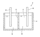
- FIG. 1 is a conceptual diagram illustrating a lithium ion secondary battery as an electricity storage device according to one embodiment of the present invention.
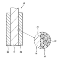
- FIG. 2 is an enlarged cross-sectional view showing a part of the negative electrode of the battery of FIG.
- the negative electrode material of the electricity storage device according to the present invention is composed of a Si-based alloy (comprising), preferably substantially composed of a Si-based alloy (consisting essentially), and more preferably composed of only a Si-based alloy.
- the negative electrode material of the electricity storage device according to another aspect of the present invention is composed of composite material, preferably substantially composed material, more preferably composed of only composite material. (Consisting of).
- the lithium ion secondary battery 2 conceptually shown in FIG. 1 includes a tank 4, an electrolytic solution 6, a separator 8, a positive electrode 10, and a negative electrode 12.
- the electrolytic solution 6 is stored in the tank 4.
- This electrolytic solution 6 contains lithium ions.
- the separator 8 partitions the tank 4 into a positive electrode chamber 14 and a negative electrode chamber 16.
- the separator 8 prevents contact between the positive electrode 10 and the negative electrode 12.
- the separator 8 has a large number of holes (not shown). Lithium ions can pass through this hole.
- the positive electrode 10 is immersed in the electrolytic solution 6 in the positive electrode chamber 14.
- the negative electrode 12 is immersed in the electrolytic solution 6 in the negative electrode chamber 16.
- FIG. 2 shows a part of the negative electrode 12.
- the negative electrode 12 includes a current collector 18 and an active material layer 20.
- the active material layer 20 includes a large number of particles 22 (powder). Each particle 22 is fixed to another particle 22 in contact with the particle 22. The particles 22 that come into contact with the current collector 18 are fixed to the current collector 18.
- the active material layer 20 is porous.
- the material (negative electrode material) of the particles 22 is a Si-based alloy.
- This alloy has a Si phase and a compound phase.
- the main component of the Si phase is Si.
- This Si phase has a Diamond structure. Elements other than Si may be dissolved in the Si phase. As described above, Si reacts with lithium ions. Since the Si phase contains Si as a main component, the negative electrode 12 including the Si phase can occlude a large amount of lithium ions. The Si phase can increase the storage capacity of the negative electrode 12.
- This alloy contains Cr. Cr forms a Si—Cr compound in the compound phase. Specific examples of the compound is CrSi 2. CrSi 2 can cause a eutectic reaction with the Si phase. In other words, the particles 22 can be formed from a Si—CrSi 2 eutectic alloy. In this eutectic alloy, the Si phase is extremely fine, and the CrSi 2 phase is also extremely fine. This compound phase relieves stress caused by expansion during charge and contraction during discharge.
- the CrSi 2 phase has a hexagonal structure.
- the space group of CrSi 2 phase belongs to P6 2 22. This phase can suppress the volume change of the Si phase during charge and discharge.
- elements such as Ti can be substituted.
- the compound phase may contain Ti together with Cr.
- this compound phase a part of Cr in the Si—CrSi 2 eutectic alloy is substituted with Ti.
- the compound phase includes a Si—Cr—Ti compound.
- Ti is presumed to increase the lattice constant of the crystal.
- the particles 22 having a compound phase having a large lattice constant it is estimated that lithium ions pass smoothly through the silicide. Further, it is estimated that a compound such as (Cr, Ti) Si 2 improves the electrical conductivity of the particles 22.
- This alloy contains one or both of Al and Sn. Both of these elements suppress the decrease in initial Coulomb efficiency as described above. Although details are unknown about the suppression of the coulomb efficiency decrease, the following is presumed. Unlike elements belonging to Cr, Ti and TCF, Al and Sn are unlikely to form silicides combined with Si. Therefore, when X-ray diffraction or EDX analysis is performed, it can be seen that Al and Sn are dissolved in Si in the alloy or can exist alone. Both Al and Sn have higher electrical conductivity than Si and silicide, and are considered to improve the electrical conductivity in the negative electrode active material and with the conductive material.
- Al and Sn are excellent in ductility, it is considered that they also have a function of suppressing the decay of the negative electrode active material accompanying Li occlusion / release, and are presumed to be a factor of excellent cycle life. .
- the alloy may contain Zr, Hf, V, Nb, Ta, Mo, W, Mn, Fe, Co, Ni or Cu.
- the alloy may contain two or more of these elements. These elements can replace Cr in the CrSi 2 phase. It is presumed that the CrSi 2 phase is refined by this substitution. The refined CrSi 2 phase relieves stress caused by expansion during charge and contraction during discharge. This battery 2 is excellent in cycle life.
- TCF% Zr% + Hf% + V% + Nb% + Ta% + Mo% + W% + Mn% + Fe% + Co% + Ni% / 2 + Cu% / 3
- Ni has the ability to suppress expansion of the negative electrode is about 1 ⁇ 2 that of other elements. Therefore, in the above formula (I), Ni% is divided by 2.
- Cu has the ability to suppress expansion of the negative electrode to about 1/3 of other elements. Therefore, in the above formula (I), Cu% is divided by 3.
- “%” represents an atomic composition percentage (at.%) Unless otherwise specified.
- the total content of TCF is less than 10%.
- a negative electrode having an alloy having a total content of less than 10% is excellent in cycle life.
- the total content is preferably less than 5% and particularly preferably less than 2%. This total content may be zero.
- the alloy may contain C, B, P, Ag, Zn, In, Ga, Ge, Pb, Bi, S, or Se.
- the alloy may contain two or more of these elements. An alloy containing these elements excessively has poor charge / discharge characteristics. These elements are added as long as the charge / discharge characteristics are not significantly adversely affected.
- TNF elements belonging to TNF. These elements are in any of the following states (a) to (c) in the alloy.
- Elements belonging to TNF are dissolved in the Si phase.
- An element belonging to TNF forms a single phase (solid solution phase of the element).
- Elements belonging to TNF form compounds with elements other than Si.
- the total content of TNF is obtained by the following mathematical formula (II).
- TNF% C% + B% + P% + Ag% + Zn% + In% + Ga% + Ge% + Pb% + Bi% + S% + Se% (II)
- the total content of TNF is 5% or less.
- a negative electrode having an alloy having a total content of 5% or less is excellent in cycle life.
- the total content is preferably less than 3%, particularly preferably less than 1%. This total content may be zero.
- Alloys are Cr, Al, Sn, Ti, Zr, Hf, V, Nb, Ta, Mo, W, Mn, Fe, Co, Ni, Cu, C, B, P, Ag, Zn, In, Ga, Ge And two or more elements selected from the group consisting of Pb, Bi, S and Se.
- the balance of this alloy is Si and inevitable impurities.
- the ratio P1 (%) is calculated by the following mathematical formula.
- P1 Cr% + Ti% + Al% + Sn% + TCF% + TNF%
- the ratio P1 is more than 25% and 40% or less.
- the ratio P1 is preferably greater than 27% and particularly preferably greater than 30%.
- the battery 2 having the negative electrode 12 with the ratio P1 of 40% or less is excellent in initial Coulomb efficiency.
- the ratio P1 is preferably less than 38% and particularly preferably less than 35%.
- the total content of Cr and Ti in the alloy is preferably 0.05% or more and 30% or less.
- a Si phase having a small crystallite size can be obtained.
- the total content is particularly preferably equal to or greater than 12%.
- a compound phase having a small crystallite size can be obtained.
- the total content is particularly preferably equal to or less than 25%.
- the ratio R1 is calculated by the following mathematical formula.
- R1 Cr% / (Cr% + Ti% + Al% + Sn% + TCF% + TNF%)
- the ratio R1 is 0.05 or more.
- An alloy having a ratio R1 of 0.05 or more has a fine structure.
- the negative electrode 12 made of this alloy has a long cycle life.
- the ratio R1 is preferably greater than 0.10 and particularly preferably greater than 0.15.
- the ratio R1 is preferably less than 0.90 and particularly preferably less than 0.80.
- the ratio R2 is calculated by the following mathematical formula.
- R2 (Al% + Sn%) / (Cr% + Ti% + Al% + Sn% + TCF% + TNF%)
- the ratio R2 is not less than 0.002 and not more than 0.400.
- a battery including the negative electrode 12 having the ratio R2 of 0.002 or more is excellent in initial Coulomb efficiency.
- the ratio R2 is preferably greater than 0.010 and particularly preferably greater than 0.100.
- An alloy having a ratio R2 of 0.400 or less can have a microstructure.
- the ratio R2 is preferably less than 0.350, and particularly preferably less than 0.300.
- the total content of Al and Sn in the alloy is preferably 0.05% or more and 15% or less.
- a battery including an alloy having a total content of 0.05% or more is excellent in initial Coulomb efficiency.
- the total content is particularly preferably equal to or greater than 2%.
- An alloy having a total content of 15% or less can have a microstructure.
- the total content is particularly preferably equal to or less than 10%.
- the ratio P2 (%) is calculated by the following mathematical formula.
- P2 4.8 ⁇ (Cr% + Ti% + TCF%) + (Al% + Sn% + TNF%)
- the ratio P2 is a parameter that correlates with the discharge capacity, and the discharge capacity can be predicted from the experimental results described later. By defining the upper limit of this equation, a sufficient discharge capacity can be ensured.
- the ratio P2 is 135% or less.
- the negative electrode having an alloy having a ratio P2 of 135% or less has a large discharge capacity.
- the ratio P2 is preferably less than 130, and particularly preferably less than 125.
- the ratio P2 is preferably 100% or more.
- the particles 22 can be manufactured by a single roll cooling method, a gas atomizing method, a disk atomizing method, or the like. In order to obtain particles 22 having a small size, it is necessary to quench the molten metal (molten raw material).
- the cooling rate is preferably 100 ° C./s or more.
- raw materials are put into a quartz tube having pores at the bottom.
- This raw material is heated and melted by a high frequency induction furnace in an argon gas atmosphere.
- the raw material flowing out from the pores falls on the surface of the copper roll and is cooled to obtain a ribbon.
- This ribbon is put into a pot (container) together with a ball (hard sphere).
- the ball material include zirconia, SUS304, and SUJ2.
- the pot material include zirconia, SUS304, and SUJ2.
- the pot is filled with argon gas and the pot is sealed.
- the ribbon is pulverized by milling to obtain particles 22. Examples of milling include a ball mill, a bead mill, a planetary ball mill, an attritor, and a vibrating ball mill.
- raw materials are put into a refractory crucible having pores at the bottom.
- This raw material is heated and melted by a high frequency induction furnace in an argon gas atmosphere.
- argon gas is injected onto the raw material flowing out from the pores.
- the raw material is rapidly cooled and solidified to obtain a powder.
- This powder is put into a pot together with a ball.
- the ball material include zirconia, SUS304, and SUJ2.
- the pot material include zirconia, SUS304, and SUJ2.
- the pot is filled with argon gas and the pot is sealed. This powder is pulverized by milling to obtain particles 22.
- milling examples include a ball mill, a bead mill, a planetary ball mill, an attritor, and a vibrating ball mill.
- the structure can be refined and combined with carbon materials, conductive metal powders, oxide powders, and other ceramic powders.
- raw materials are put into a refractory crucible having pores at the bottom.
- This raw material is heated and melted by a high frequency induction furnace in an argon gas atmosphere.
- an argon gas atmosphere the raw material flowing out from the pores is dropped onto a disk that rotates at high speed.
- the rotation speed is 40000 rpm to 60000 rpm.
- the raw material is rapidly cooled by the disk and solidified to obtain a powder. This powder is milled.
- the milling described above for the gas atomization method can also be employed for disk atomization.
- raw materials having the composition shown in Table 1 were prepared. Powders were produced from the respective raw materials by the gas atomization method described above. This powder was classified, and a powder having a particle size of 20 ⁇ m or less was used as a negative electrode particle. A 10 mass% conductive material (acetylene black), 15 mass% binder (polyimide), and 10 mass% solvent (N-methylpyrrolidone) were mixed with the particles in a mortar to obtain a slurry. This slurry was applied onto a copper foil as a current collector, and dried under reduced pressure using a vacuum dryer. The solvent was evaporated by this drying to obtain an active material layer. The active material layer and the copper foil were pressed with a hand press. This active material layer and copper foil were punched into a shape suitable for a coin-type cell to obtain a negative electrode.
- a 10 mass% conductive material acetylene black
- 15 mass% binder polyimide
- solvent N-methylpyrrolidone
- LiPF 6 lithium hexafluorophosphate
- a separator and a positive electrode having a shape suitable for a coin-type cell were prepared.
- This positive electrode is made of lithium.
- the separator was immersed in the electrolytic solution under reduced pressure and allowed to stand for 5 hours to fully infiltrate the separator with the electrolytic solution.
- a negative electrode, a separator and a positive electrode were incorporated in the tank.
- the tank was filled with an electrolytic solution to obtain a coin-type cell.
- No. Nos. 1 to 11 are compositions of negative electrode materials according to examples of the present invention.
- 12 to 27 are compositions of the negative electrode material according to the comparative example.
- the initial thickness of the negative electrode active material layer and the thickness of the negative electrode active material layer after 50 cycles of charging and discharging were measured.
- the ratio of the thickness after charging / discharging to the initial thickness (negative electrode expansion coefficient) was calculated. The results are shown in Table 2 below.
- the cell according to Comparative Example 12 has a large negative electrode expansion coefficient because the value of the ratio P1 is small.
- the cell according to Comparative Example 13 is inferior in discharge capacity and inferior in initial Coulomb efficiency since the values of the ratio P1 and the ratio P2 are large.
- the cell according to Comparative Example 14 is inferior in capacity maintenance rate because the value of the ratio R1 is small.
- the cells according to Comparative Examples 15 and 16 are inferior in initial Coulomb efficiency because the value of the ratio R2 is small.
- the cell according to Comparative Example 17 is inferior in capacity maintenance rate because the value of the ratio R2 is large.
- the cell according to Comparative Example 18 is inferior in discharge capacity because the value of the ratio P2 is large.
- the cell according to Comparative Example 19 is inferior in negative electrode expansion coefficient because the value of the ratio P1 is small.
- the cell according to Comparative Example 20 is inferior in discharge capacity and inferior in initial Coulomb efficiency since the values of ratio P1 and ratio P2 are large.
- the cell according to Comparative Example 21 is inferior in capacity maintenance rate because the value of the ratio R1 is small.
- the cells according to Comparative Examples 22 and 23 are inferior in initial Coulomb efficiency because the value of the ratio R2 is small.
- the cell according to Comparative Example 24 is inferior in capacity maintenance rate because the value of the ratio R2 is large.
- the cell according to Comparative Example 25 is inferior in discharge capacity because the ratio P2 is large.
- the cells according to Comparative Examples 26 and 27 are inferior in capacity maintenance rate because the value of the ratio R1 is small.
- Experiment B Experiments were performed using an element belonging to TCF or an alloy containing an element belonging to TNF. In this experiment, as in Experiment A, a bipolar coin-type cell was used.
- raw materials having the compositions shown in Tables 3 and 4 were prepared. Powders were produced from the respective raw materials by the gas atomization method described above. This powder was classified to obtain a powder having a particle size of 106 ⁇ m or less. This powder was put into a metal container together with a hard sphere made of chrome steel, mounted on a planetary ball mill apparatus, and stirred for 30 hours. The obtained powder was used as negative electrode particles. Using these particles, a coin-type cell was obtained in the same manner as in Experiment A.
- No. 28 to 62 are compositions of the negative electrode material according to the example of the present invention
- Nos. 63 to 72 are compositions of the negative electrode material according to the comparative example.
- the cell according to Comparative Example 63 is inferior in negative electrode expansion coefficient because the value of the ratio P1 is small.
- the cell according to Comparative Example 64 has a large value of the ratio P1 and the ratio P2, so that the discharge capacity is inferior and the initial coulomb efficiency is inferior.
- the cell according to Comparative Example 65 is inferior in capacity maintenance rate because the ratio R1 is small. Since the cell according to Comparative Example 66 has a small ratio R2, the initial Coulomb efficiency is inferior.
- the cell according to Comparative Example 67 is inferior in the capacity maintenance rate because the value of the ratio R2 is large.
- the cell according to Comparative Example 68 is inferior in discharge capacity because the value of the ratio P2 is large.
- the cells according to Comparative Examples 69 and 70 are inferior in capacity retention because the total content of TCF is large. Since the cells according to Comparative Examples 71 and 72 have a large total content of TNF, the capacity retention rate is inferior.
- Example 73 In the same manner as in Example 61 of Experiment B, a powder having a particle size of 106 ⁇ m or less was obtained. This powder and natural graphite powder were put into a metal container. The mass mixing ratio of both powders is 97/3. Further, a hard sphere made of chrome steel was put into this container, and it was attached to a planetary ball mill device and stirred for 30 hours. The obtained powder was used as negative electrode particles. Using these particles, a coin-type cell was obtained in the same manner as in Experiment A.
- Example 74 A coin-type cell of Example 74 was obtained in the same manner as Example 73 except that zinc powder was used instead of natural graphite powder and the powder mass mixing ratio was 80/20.
- Example 75 A coin-type cell of Example 75 was obtained in the same manner as Example 73 except that SiO 2 powder was used instead of natural graphite powder and the powder mass mixing ratio was set to 92/8.
- the discharge capacity, capacity retention rate, initial coulomb efficiency, and negative electrode expansion rate were measured in the same manner as in Experiment A.
- the discharge capacity was 640 mAh / g
- the capacity retention rate was 96.2%
- the initial Coulomb efficiency was 84.2%
- the negative electrode expansion rate was 142%.
- the discharge capacity was 570 mAh / g
- the capacity retention rate was 93.0%
- the initial Coulomb efficiency was 85.0%
- the negative electrode expansion rate was 150%.
- the discharge capacity was 620 mAh / g
- the capacity retention rate was 94.5%
- the initial Coulomb efficiency was 81.0%
- the negative electrode expansion coefficient was 138%. It was.
- the cells according to Examples 73 to 75 are excellent in various performances.
- the negative electrode described above can be applied not only to a lithium ion secondary battery but also to an electricity storage device such as an all-solid lithium ion secondary battery or a hybrid capacitor.
Landscapes
- Chemical & Material Sciences (AREA)
- Engineering & Computer Science (AREA)
- Materials Engineering (AREA)
- Chemical Kinetics & Catalysis (AREA)
- General Chemical & Material Sciences (AREA)
- Electrochemistry (AREA)
- Power Engineering (AREA)
- Metallurgy (AREA)
- Microelectronics & Electronic Packaging (AREA)
- Organic Chemistry (AREA)
- Mechanical Engineering (AREA)
- Manufacturing & Machinery (AREA)
- Battery Electrode And Active Subsutance (AREA)
- Manufacture Of Metal Powder And Suspensions Thereof (AREA)
- Electric Double-Layer Capacitors Or The Like (AREA)
- Cell Electrode Carriers And Collectors (AREA)
Abstract
蓄電デバイスの負極12は、集電体18と、この集電体18の表面に固着した多数の粒子22とを備えている。この粒子22は、Si系合金からなる。この合金は、Cr、Al、Sn、Ti、Zr、Hf、V、Nb、Ta、Mo、W、Mn、Fe、Co、Ni、Cu、C、B、P、Ag、Zn、In、Ga、Ge、Pb、Bi、S及びSeからなる群から選択される2種以上の元素を含んでおり、残部がSi及び不可避的不純物である。この合金は、Crを含む。比(Cr%/(Cr%+Ti%+Al%+Sn%+TCF%+TNF%))は、0.05以上である。この合金は、Al及び/又はSnを含む。比((Al%+Sn%)/(Cr%+Ti%+Al%+Sn%+TCF%+TNF%))は、0.002以上0.400以下である。
Description
この出願は、2014年3月13日に出願された日本国特許出願2014-050624号に基づく優先権を主張するものであり、これらの全体の開示内容が参照により本明細書に組み込まれる。
本発明は、リチウムイオン二次電池、全固体リチウムイオン二次電池、ハイブリットキャパシタ等の蓄電デバイスの負極に適した材料に関する。
リチウム二次電池の負極活物質には従来より炭素材料からなる粉末が用いられているが、炭素材料は理論容量が372mAh/gと低く、更なる高容量化には限界がある。これに対し、近年ではSn、AlおよびSiなどの炭素材料よりも理論容量の高い金属材料の適用が検討、実用化されている。特に、Siは4000mAh/gを超える理論容量があり、有望な材料である。しかし、これら炭素に代わる金属材料をリチウムイオン二次電池の負極活物質として適用する際には、高容量は得られるものの、サイクル寿命が短いという課題がある。
この課題に対し、Siに種々の元素を添加し、純Si粉末ではなくSi系合金粉末とし、微細組織を得ることで改善する方法が多く提案されている。特許文献1では、共晶となる量、もしくはそれ以上の過共晶となる量のCoなどの元素を添加し、これを100℃/s以上の冷却速度で凝固させることによって、Si相の短軸粒径が5μm以下となる合金粉末を得ている。このような微細Si相を有するSi系合金粉末を用いることでサイクル寿命を改善している。すなわち、Liを吸蔵、放出しない珪化物を生成させることにより、微細なSi相のLi吸蔵、放出時の体積変化を抑制する効果を得ている。
さらに、このようなSi系合金の適用によるサイクル寿命改善技術を発展させ、より微細な組織が得られ、より優れたサイクル寿命を有する合金として、発明者は、特許文献2において、所定量のCr、Ti、AlおよびSnを添加することで、Si相とCrSi2相の微細共晶組織が得られることを提案している。この特許文献2は、Siへの添加元素として、特にCrが優れることを見出したものである。
一方、リチウムイオン二次電池の負極に用いるSi系合金粉末は、多くの場合、ボールミルなどにより数μm以下に粉砕加工されたり、結晶性を低下させて使用する。さらに、特許文献4~6のように、ボールミルによる加工の際に、炭素材料、導電性金属粉末、酸化物粉末を導入し、これらとSi系合金粉末を複合化することにより、一段と優れた充放電特性を実現する方法が提案されている。
第54回電池討論会、講演要旨集、(2013)P138
本発明は、特許文献2の技術をベースとし、さらに充放電特性を改善させる技術を確立したものである。また、その背景には、以下に記述するような、本発明の周辺技術の変化がある。すなわち、近年、リチウムイオン電池のSi系負極用材料を取り巻く環境は大きく変化しており、負極中の導電材やバインダー、また、電解液や電解質、セパレーター、さらには正極材料の改良など、Si系負極材料の最大の欠点である低いサイクル寿命特性を補う電池構成全体の改良が盛んに検討されている(一例として特許文献3などが挙げられる)。このような状況において、同じSi系合金を負極活物質として用いても、サイクル寿命が向上するケースが増えてきた。特許文献2において、Cr、Ti、AlおよびSnの合計添加量が21%を超えると、サイクル寿命が低下することを記述したが、上述のような電池構成全体の改良によって、これら添加元素の添加量は更に高い水準でも利用可能な場合が出てきた。しかしながら、これら添加元素の添加量を上げた場合、他の問題も発生する。すなわち、これら添加元素の添加量が増えると、残部であるSi量が減り、例えば非特許文献1に示されるような、初期クーロン効率の低下が顕著となる。
同様の問題は、リチウムイオン二次電池以外の蓄電デバイスにおいても生じている。
本発明の目的は、放電容量、サイクル寿命、初回クーロン効率及び負極膨張率に優れる蓄電デバイス用負極が得られうる材料の提供にある。
本発明者らは特許文献2の発明よりもCr、Ti、AlおよびSnなどから選択される元素の添加量を高くするとともに、Al及び/又はSnを必須元素として含有させることにより、上記のような初期クーロン効率の低下を抑制できることを見出し、本発明に至った。さらに、全添加元素の合計量を高くすることで、充放電にともなう負極の厚さ増大を著しく抑制できる効果も得られるため、特許文献2の発明よりも総合特性に優れたSi系合金粉末が提供される。
本発明の一態様によれば、Si系合金からなり、
前記Si系合金が、
Cr、Al、Sn、Ti、Zr、Hf、V、Nb、Ta、Mo、W、Mn、Fe、Co、Ni、Cu、C、B、P、Ag、Zn、In、Ga、Ge、Pb、Bi、S及びSeからなる群から選択される2種以上の元素を含んでおり、残部がSi及び不可避的不純物であり、
TCF(%)が下記数式(I)で定義され、TNF(%)が下記数式(II)で定義されるとき、前記Si系合金が下記数式(1)から(6)を満たす、蓄電デバイスの負極材料が提供される。
(I)TCF%=Zr%+Hf%+V%+Nb%+Ta%+Mo%+W%+Mn%+Fe%+Co%+Ni%/2+Cu%/3
(II)TNF%=C%+B%+P%+Ag%+Zn%+In%+Ga%+Ge%+Pb%+Bi%+S%+Se%
(1)25%<Cr%+Ti%+Al%+Sn%+TCF%+TNF%≦40%
(2)0.05≦Cr%/(Cr%+Ti%+Al%+Sn%+TCF%+TNF%)
(3)0.002≦(Al%+Sn%)/(Cr%+Ti%+Al%+Sn%+TCF%+TNF%)≦0.400
(4)4.8×(Cr%+Ti%+TCF%)+(Al%+Sn%+TNF%)≦135%
(5)TCF%<10%
(6)TNF%≦5%
前記Si系合金が、
Cr、Al、Sn、Ti、Zr、Hf、V、Nb、Ta、Mo、W、Mn、Fe、Co、Ni、Cu、C、B、P、Ag、Zn、In、Ga、Ge、Pb、Bi、S及びSeからなる群から選択される2種以上の元素を含んでおり、残部がSi及び不可避的不純物であり、
TCF(%)が下記数式(I)で定義され、TNF(%)が下記数式(II)で定義されるとき、前記Si系合金が下記数式(1)から(6)を満たす、蓄電デバイスの負極材料が提供される。
(I)TCF%=Zr%+Hf%+V%+Nb%+Ta%+Mo%+W%+Mn%+Fe%+Co%+Ni%/2+Cu%/3
(II)TNF%=C%+B%+P%+Ag%+Zn%+In%+Ga%+Ge%+Pb%+Bi%+S%+Se%
(1)25%<Cr%+Ti%+Al%+Sn%+TCF%+TNF%≦40%
(2)0.05≦Cr%/(Cr%+Ti%+Al%+Sn%+TCF%+TNF%)
(3)0.002≦(Al%+Sn%)/(Cr%+Ti%+Al%+Sn%+TCF%+TNF%)≦0.400
(4)4.8×(Cr%+Ti%+TCF%)+(Al%+Sn%+TNF%)≦135%
(5)TCF%<10%
(6)TNF%≦5%
本発明の他の一態様によれば、
Si系合金と、
炭素材料、導電性金属粉末、酸化物粉末、及びセラミックス粉末から選択されるいずれか一種以上の粉末と
の複合化材料からなり、
前記Si系合金が、
Cr、Al、Sn、Ti、Zr、Hf、V、Nb、Ta、Mo、W、Mn、Fe、Co、Ni、Cu、C、B、P、Ag、Zn、In、Ga、Ge、Pb、Bi、S及びSeからなる群から選択される2種以上の元素を含んでおり、残部がSi及び不可避的不純物であり、
TCF(%)が下記数式(I)で定義され、TNF(%)が下記数式(II)で定義されるとき、前記Si系合金が下記数式(1)から(6)を満たす、蓄電デバイスの負極材料が提供される。
(I)TCF%=Zr%+Hf%+V%+Nb%+Ta%+Mo%+W%+Mn%+Fe%+Co%+Ni%/2+Cu%/3
(II)TNF%=C%+B%+P%+Ag%+Zn%+In%+Ga%+Ge%+Pb%+Bi%+S%+Se%
(1)25%<Cr%+Ti%+Al%+Sn%+TCF%+TNF%≦40%
(2)0.05≦Cr%/(Cr%+Ti%+Al%+Sn%+TCF%+TNF%)
(3)0.002≦(Al%+Sn%)/(Cr%+Ti%+Al%+Sn%+TCF%+TNF%)≦0.400
(4)4.8×(Cr%+Ti%+TCF%)+(Al%+Sn%+TNF%)≦135%
(5)TCF%<10%
(6)TNF%≦5%
Si系合金と、
炭素材料、導電性金属粉末、酸化物粉末、及びセラミックス粉末から選択されるいずれか一種以上の粉末と
の複合化材料からなり、
前記Si系合金が、
Cr、Al、Sn、Ti、Zr、Hf、V、Nb、Ta、Mo、W、Mn、Fe、Co、Ni、Cu、C、B、P、Ag、Zn、In、Ga、Ge、Pb、Bi、S及びSeからなる群から選択される2種以上の元素を含んでおり、残部がSi及び不可避的不純物であり、
TCF(%)が下記数式(I)で定義され、TNF(%)が下記数式(II)で定義されるとき、前記Si系合金が下記数式(1)から(6)を満たす、蓄電デバイスの負極材料が提供される。
(I)TCF%=Zr%+Hf%+V%+Nb%+Ta%+Mo%+W%+Mn%+Fe%+Co%+Ni%/2+Cu%/3
(II)TNF%=C%+B%+P%+Ag%+Zn%+In%+Ga%+Ge%+Pb%+Bi%+S%+Se%
(1)25%<Cr%+Ti%+Al%+Sn%+TCF%+TNF%≦40%
(2)0.05≦Cr%/(Cr%+Ti%+Al%+Sn%+TCF%+TNF%)
(3)0.002≦(Al%+Sn%)/(Cr%+Ti%+Al%+Sn%+TCF%+TNF%)≦0.400
(4)4.8×(Cr%+Ti%+TCF%)+(Al%+Sn%+TNF%)≦135%
(5)TCF%<10%
(6)TNF%≦5%
好ましい態様によれば、この負極材料は、合金の溶湯を100℃/s以上の速度で冷却して凝固することで得られる。
好ましい態様によれば、この負極材料は、少なくとも合金の粉末と硬質球とを、容器内で撹拌し、この粉末を粉砕することで得られる。
本発明の他の一態様によれば、上記蓄電デバイスの負極材料の製造方法であって、上記Si系合金の溶湯を100℃/s以上の速度で冷却して凝固させる工程を含む、製造方法が提供される。好ましい態様によれば、上記冷却工程の前に、上記Si系合金を溶融させて溶湯を得る工程をさらに含む蓄電デバイスの負極材料の製造方法が提供される。
本発明の他の一態様によれば、上記蓄電デバイスの負極材料の製造方法であって、少なくとも上記Si系合金の粉末又はリボンと硬質球とを、容器内で撹拌し、該Si系合金の粉末又はリボンを粉砕する工程を含む、製造方法が提供される。好ましい態様によれば、上記粉砕工程の前に、上記Si系合金の溶湯を100℃/s以上の速度で冷却して凝固させる工程をさらに含む、蓄電デバイスの負極材料の製造方法が提供される。
本発明の他の一態様によれば、複合化材料からなる上記蓄電デバイスの負極材料の製造方法であって、上記Si系合金の粉末又はリボンと、硬質球と、炭素材料、導電性金属粉末、酸化物粉末、及びセラミックス粉末から選択されるいずれか一種以上の粉末とを容器内で撹拌し、該Si系合金の粉末又はリボンを前記いずれか一種以上の粉末と複合化する工程を含む、製造方法が提供される。
本発明の他の一態様によれば、集電体と、この集電体の表面に固着した多数の粒子とを備えており、
前記粒子が、Si系合金からなり、
前記Si系合金が、Cr、Al、Sn、Ti、Zr、Hf、V、Nb、Ta、Mo、W、Mn、Fe、Co、Ni、Cu、C、B、P、Ag、Zn、In、Ga、Ge、Pb、Bi、S及びSeからなる群から選択される2種以上の元素を含んでおり、残部がSi及び不可避的不純物であり、
TCF(%)が下記数式(I)で定義され、TNF(%)が下記数式(II)で定義されるとき、前記Si系合金が下記数式(1)から(6)を満たす、蓄電デバイスの負極が提供される。
(I)TCF%=Zr%+Hf%+V%+Nb%+Ta%+Mo%+W%+Mn%+Fe%+Co%+Ni%/2+Cu%/3
(II)TNF%=C%+B%+P%+Ag%+Zn%+In%+Ga%+Ge%+Pb%+Bi%+S%+Se%
(1)25%<Cr%+Ti%+Al%+Sn%+TCF%+TNF%≦40%
(2)0.05≦Cr%/(Cr%+Ti%+Al%+Sn%+TCF%+TNF%)
(3)0.002≦(Al%+Sn%)/(Cr%+Ti%+Al%+Sn%+TCF%+TNF%)≦0.400
(4)4.8×(Cr%+Ti%+TCF%)+(Al%+Sn%+TNF%)≦135%
(5)TCF%<10%
(6)TNF%≦5%
前記粒子が、Si系合金からなり、
前記Si系合金が、Cr、Al、Sn、Ti、Zr、Hf、V、Nb、Ta、Mo、W、Mn、Fe、Co、Ni、Cu、C、B、P、Ag、Zn、In、Ga、Ge、Pb、Bi、S及びSeからなる群から選択される2種以上の元素を含んでおり、残部がSi及び不可避的不純物であり、
TCF(%)が下記数式(I)で定義され、TNF(%)が下記数式(II)で定義されるとき、前記Si系合金が下記数式(1)から(6)を満たす、蓄電デバイスの負極が提供される。
(I)TCF%=Zr%+Hf%+V%+Nb%+Ta%+Mo%+W%+Mn%+Fe%+Co%+Ni%/2+Cu%/3
(II)TNF%=C%+B%+P%+Ag%+Zn%+In%+Ga%+Ge%+Pb%+Bi%+S%+Se%
(1)25%<Cr%+Ti%+Al%+Sn%+TCF%+TNF%≦40%
(2)0.05≦Cr%/(Cr%+Ti%+Al%+Sn%+TCF%+TNF%)
(3)0.002≦(Al%+Sn%)/(Cr%+Ti%+Al%+Sn%+TCF%+TNF%)≦0.400
(4)4.8×(Cr%+Ti%+TCF%)+(Al%+Sn%+TNF%)≦135%
(5)TCF%<10%
(6)TNF%≦5%
本発明のさらに他の態様によれば、正極と負極とを備えており、
前記負極が、集電体と、この集電体の表面に固着した多数の粒子とを備えており、
前記粒子が、Si系合金からなり、
前記Si系合金が、Cr、Al、Sn、Ti、Zr、Hf、V、Nb、Ta、Mo、W、Mn、Fe、Co、Ni、Cu、C、B、P、Ag、Zn、In、Ga、Ge、Pb、Bi、S及びSeからなる群から選択される2種以上の元素を含んでおり、残部がSi及び不可避的不純物であり、
TCF(%)が下記数式(I)で定義され、TNF(%)が下記数式(II)で定義されるとき、前記Si系合金が下記数式(1)から(6)を満たす、蓄電デバイスが提供される。
(I)TCF%=Zr%+Hf%+V%+Nb%+Ta%+Mo%+W%+Mn%+Fe%+Co%+Ni%/2+Cu%/3
(II)TNF%=C%+B%+P%+Ag%+Zn%+In%+Ga%+Ge%+Pb%+Bi%+S%+Se%
(1)25%<Cr%+Ti%+Al%+Sn%+TCF%+TNF%≦40%
(2)0.05≦Cr%/(Cr%+Ti%+Al%+Sn%+TCF%+TNF%)
(3)0.002≦(Al%+Sn%)/(Cr%+Ti%+Al%+Sn%+TCF%+TNF%)≦0.400
(4)4.8×(Cr%+Ti%+TCF%)+(Al%+Sn%+TNF%)≦135%
(5)TCF%<10%
(6)TNF%≦5%
前記負極が、集電体と、この集電体の表面に固着した多数の粒子とを備えており、
前記粒子が、Si系合金からなり、
前記Si系合金が、Cr、Al、Sn、Ti、Zr、Hf、V、Nb、Ta、Mo、W、Mn、Fe、Co、Ni、Cu、C、B、P、Ag、Zn、In、Ga、Ge、Pb、Bi、S及びSeからなる群から選択される2種以上の元素を含んでおり、残部がSi及び不可避的不純物であり、
TCF(%)が下記数式(I)で定義され、TNF(%)が下記数式(II)で定義されるとき、前記Si系合金が下記数式(1)から(6)を満たす、蓄電デバイスが提供される。
(I)TCF%=Zr%+Hf%+V%+Nb%+Ta%+Mo%+W%+Mn%+Fe%+Co%+Ni%/2+Cu%/3
(II)TNF%=C%+B%+P%+Ag%+Zn%+In%+Ga%+Ge%+Pb%+Bi%+S%+Se%
(1)25%<Cr%+Ti%+Al%+Sn%+TCF%+TNF%≦40%
(2)0.05≦Cr%/(Cr%+Ti%+Al%+Sn%+TCF%+TNF%)
(3)0.002≦(Al%+Sn%)/(Cr%+Ti%+Al%+Sn%+TCF%+TNF%)≦0.400
(4)4.8×(Cr%+Ti%+TCF%)+(Al%+Sn%+TNF%)≦135%
(5)TCF%<10%
(6)TNF%≦5%
本発明に係る負極材料を含む負極は、放電容量、サイクル寿命、初回クーロン効率及び負極膨張率に優れる。
本発明による蓄電デバイスの負極材料は、Si系合金からなり(comprising)、好ましくはSi系合金から実質的になり(consisting essentially of)、より好ましくはSi系合金のみからなる(consisting of)。また、本発明の他の態様による蓄電デバイスの負極材料は、複合化材料からなり(comprising)、好ましくは複合化材料から実質的になり(consisting essentially of)、より好ましくは複合化材料のみからなる(consisting of)。以下、適宜図面を参照しつつ、好ましい実施形態に基づいて本発明を詳細に説明する。
図1に概念的に示されたリチウムイオン二次電池2は、槽4、電解液6、セパレータ8、正極10及び負極12を備えている。電解液6は、槽4に蓄えられている。この電解液6は、リチウムイオンを含んでいる。セパレータ8は、槽4を、正極室14及び負極室16に区画している。セパレータ8により、正極10と負極12との当接が防止される。このセパレータ8は、多数の孔(図示されず)を備えている。リチウムイオンは、この孔を通過しうる。正極10は、正極室14において、電解液6に浸漬されている。負極12は、負極室16において、電解液6に浸漬されている。
図2には、負極12の一部が示されている。この負極12は、集電体18と、活物質層20とを備えている。活物質層20は、多数の粒子22(粉末)を含んでいる。それぞれの粒子22は、この粒子22に当接する他の粒子22と固着している。集電体18に当接する粒子22は、この集電体18に固着している。活物質層20は、多孔質である。
粒子22の材質(負極材料)は、Si系合金である。この合金は、Si相と化合物相とを有している。Si相の主成分は、Siである。このSi相は、Diamond構造を有する。Si相にSi以外の元素が固溶していてもよい。前述の通り、Siはリチウムイオンと反応する。Si相はSiを主成分としているので、このSi相を含む負極12は、大量のリチウムイオンを吸蔵しうる。Si相は、負極12の蓄電容量を高めうる。
この合金は、Crを含有する。Crは、化合物相において、Si-Cr化合物を形成する。化合物の具体例は、CrSi2である。CrSi2は、Si相と共晶反応を起こしうる。換言すれば、粒子22は、Si-CrSi2共晶合金から形成されうる。この共晶合金では、Si相は極めて微細であり、CrSi2相も極めて微細である。この化合物相は、充電時の膨張及び放電時の収縮によって生じる応力を緩和する。
CrSi2相は、Hexagonal構造を有する。CrSi2相の空間群は、P6222に属する。この相は、充放電時のSi相の体積変化を抑制しうる。この化合物では、Ti等の元素が置換しうる。
化合物相が、Crと共に、Tiを含有していてもよい。この化合物相では、Si-CrSi2共晶合金のCrの一部が、Tiで置換される。換言すれば、化合物相は、Si-Cr-Ti化合物を含む。Tiは、結晶の格子定数を増加させると推測される。格子定数の大きな化合物相を有する粒子22では、珪化物中を、リチウムイオンが円滑に通過すると推測される。さらに、(Cr,Ti)Si2等の化合物は、粒子22の電気伝導性を向上させると推測される。
この合金は、Al及びSnのいずれか一方又は両方を含む。これら両元素は、上述のように初期クーロン効率の低下を抑制する。このクーロン効率低下の抑制について、詳細は不明であるが以下のことが推測される。AlおよびSnはCr、TiおよびTCFに属する元素と異なり、Siと化合した珪化物を生成しにくい。したがって、X線回折やEDX分析を行なうと、AlおよびSnは合金中でSiに固溶しているか、もしくは単独で存在しうることがわかる。AlおよびSnはいずれもSiや珪化物と比較すると電気伝導性が高く、負極活物質内や導電材との電気伝導性を改善すると考えられる。
さらに、従来、Si相の体積膨張を抑制しサイクル寿命を改善するために各種の化合物が適用されてきたが、多くの場合、これら化合物は硬質であり、Si相の膨張・収縮を強制的に抑え込み制限する作用を有すると考えられる。このような強制的な抑え込みの方法は、Siの体積変化に対する物理的な抵抗となり、結果として、Si相が本来持つLi吸蔵キャパシティーまでLiを吸蔵させる場合には、内部抵抗として現れる。同様に、一旦膨張したSi相がLiを放出する際には、やはり化合物の変形がSi相の収縮に追随できず、Si相は元の体積まで戻るのに大きな物理的抵抗を受け、結果として、吸蔵したLiを放出しきれないことがある。そして、放出しきれなかったこのLiが、特に初回のクーロン効率(放電量/充電量×100(%))を低下させる原因となると考えられる。実際に、非特許文献1に示されたように、Si相の体積変化を強制的に抑え込むSi相以外の相が増え、Si相が減るとともに初回クーロン効率が低下している。これに対し、本発明で添加されたAlおよび/もしくはSnは、Siや珪化物と比較し、著しく軟質であるとともに延性も高い。したがって、特にLiを放出する際のSi相の体積収縮の抵抗になりにくいと考えられ、本発明では特許文献2の発明よりもCrやTiなどの合計添加量が高く設定され、Si相の生成量が少ないにも関わらず、初回クーロン効率の低下が小さいと考えられる。このような、電気伝導性の改善とSi相の体積収縮の抵抗になりにくい特長が、本発明におけるAlおよび/もしくはSn添加による、初回クーロン効率の低下抑制の要因であると推測される。
また、Cu系珪化物やSnCu系化合物のように比較的軟質な化合物を利用する提案もあるが、これらの化合物と比較しても、AlやSnは格段に硬度が低い。さらに、AlとSnはSiほどではないが、これ自身もLiを吸蔵出来ることからもわかるとおり、Liが相の内部を移動する際の抵抗が、上述の化合物などと比較しても格段に低く、これもスムーズな充放電を可能とする要因であり、本発明合金の初回クーロン効率の改善に寄与すると考えられる。
またさらに、AlとSnは延性にも優れることから、Li吸蔵・放出にともなう負極活物質の崩壊を抑制する働きもあると考えられ、優れたサイクル寿命の要因となっているものと推測される。
合金が、Zr、Hf、V、Nb、Ta、Mo、W、Mn、Fe、Co、Ni又はCuを含有してもよい。合金が、これらの元素の2種以上を含有してもよい。これらの元素は、CrSi2相のCrと置換しうる。この置換により、CrSi2相が微細化されると推測される。微細化されたCrSi2相は、充電時の膨張及び放電時の収縮によって生じる応力を緩和する。この電池2は、サイクル寿命に優れる。
Zr、Hf、V、Nb、Ta、Mo、W、Mn、Fe、Co、Ni及びCuは、TCFに属する元素である。これらの元素は、合金において珪化物を形成する。これらの元素は、充放電の繰り返しによる負極の膨張を抑制する。TCFの合計含有率は、下記の数式(I)によって得られる。
TCF%=Zr%+Hf%+V%+Nb%+Ta%+Mo%+W%+Mn%+Fe%+ Co%+Ni%/2+Cu%/3 (I)
Niは、負極の膨張を抑制する能力が他の元素の1/2程度である。従って、上記数式(I)において、Ni%が2で除されている。Cuは、負極の膨張を抑制する能力が他の元素の1/3程度である。従って、上記数式(I)において、Cu%が3で除されている。本明細書において、「%」は、特に言及が無い限り、原子組成百分率(at.%)を表す。
TCF%=Zr%+Hf%+V%+Nb%+Ta%+Mo%+W%+Mn%+Fe%+ Co%+Ni%/2+Cu%/3 (I)
Niは、負極の膨張を抑制する能力が他の元素の1/2程度である。従って、上記数式(I)において、Ni%が2で除されている。Cuは、負極の膨張を抑制する能力が他の元素の1/3程度である。従って、上記数式(I)において、Cu%が3で除されている。本明細書において、「%」は、特に言及が無い限り、原子組成百分率(at.%)を表す。
TCFの合計含有率は、10%未満である。この合計含有率が10%未満である合金を有する負極は、サイクル寿命に優れる。この観点から、この合計含有率は5%未満が好ましく、2%未満が特に好ましい。この合計含有率がゼロでもよい。
合金が、C、B、P、Ag、Zn、In、Ga、Ge、Pb、Bi、S又はSeを含有してもよい。合金が、これらの元素の2種以上を含有してもよい。これらの元素を過剰に含む合金は、充放電特性に劣る。充放電特性に大幅な悪影響を与えない範囲で、これらの元素が添加される。
C、B、P、Ag、Zn、In、Ga、Ge、Pb、Bi、S及びSeは、TNFに属する元素である。これらの元素は、合金において、下記(a)から(c)のいずれかの状態にある。
(a)TNFに属する元素が、Si相に固溶する。
(b)TNFに属する元素が、単体相(その元素の固溶体相)を形成する。
(c)TNFに属する元素が、Si以外の元素と化合物を形成する。
TNFの合計含有率は、下記の数式(II)によって得られる。
TNF%=C%+B%+P%+Ag%+Zn%+In%+Ga%+Ge%+Pb%+ Bi%+S%+Se% (II)
(a)TNFに属する元素が、Si相に固溶する。
(b)TNFに属する元素が、単体相(その元素の固溶体相)を形成する。
(c)TNFに属する元素が、Si以外の元素と化合物を形成する。
TNFの合計含有率は、下記の数式(II)によって得られる。
TNF%=C%+B%+P%+Ag%+Zn%+In%+Ga%+Ge%+Pb%+ Bi%+S%+Se% (II)
TNFの合計含有率は、5%以下である。この合計含有率が5%以下である合金を有する負極は、サイクル寿命に優れる。この観点から、この合計含有率は3%未満が好ましく、1%未満が特に好ましい。この合計含有率がゼロでもよい。
合金は、Cr、Al、Sn、Ti、Zr、Hf、V、Nb、Ta、Mo、W、Mn、Fe、Co、Ni、Cu、C、B、P、Ag、Zn、In、Ga、Ge、Pb、Bi、S及びSeからなる群から選択される2種以上の元素を含む。この合金の残部は、Si及び不可避的不純物である。
本明細書では、下記の数式により、比率P1(%)が算出される。
P1=Cr%+Ti%+Al%+Sn%+TCF%+TNF%
比率P1は、25%を超えて40%以下である。比率P1が25%を超えている負極は、充放電の繰り返しに起因する膨張が抑制される。この観点から、比率P1は、27%を超えることが好ましく、30%を超えることが特に好ましい。比率P1が40%以下である負極12を有する電池2は、初期のクーロン効率に優れる。この観点から、比率P1は38%未満が好ましく、35%未満が特に好ましい。
P1=Cr%+Ti%+Al%+Sn%+TCF%+TNF%
比率P1は、25%を超えて40%以下である。比率P1が25%を超えている負極は、充放電の繰り返しに起因する膨張が抑制される。この観点から、比率P1は、27%を超えることが好ましく、30%を超えることが特に好ましい。比率P1が40%以下である負極12を有する電池2は、初期のクーロン効率に優れる。この観点から、比率P1は38%未満が好ましく、35%未満が特に好ましい。
合金におけるCrとTiとの合計含有率は、0.05%以上30%以下が好ましい。合計含有率が0.05%以上である合金では、結晶子サイズが小さなSi相が得られうる。この観点から、合計含有率は12%以上が特に好ましい。合計含有率が30%以下である合金では、結晶子サイズが小さな化合物相が得られうる。この観点から、合計含有率は25%以下が特に好ましい。
本明細書では、下記の数式により、比R1が算出される。
R1=Cr%/(Cr%+Ti%+Al%+Sn%+TCF%+TNF%)
比R1は、0.05以上である。比R1が0.05以上である合金では、組織が微細である。この合金からなる負極12は、サイクル寿命が長い。この観点から、比R1は0.10を超えることが好ましく、0.15を超えることが特に好ましい。前述の通り、Crの一部がTiと置換した組織では、結晶の格子定数が大きい。この観点から、比R1は0.90未満が好ましく、0.80未満が特に好ましい。
R1=Cr%/(Cr%+Ti%+Al%+Sn%+TCF%+TNF%)
比R1は、0.05以上である。比R1が0.05以上である合金では、組織が微細である。この合金からなる負極12は、サイクル寿命が長い。この観点から、比R1は0.10を超えることが好ましく、0.15を超えることが特に好ましい。前述の通り、Crの一部がTiと置換した組織では、結晶の格子定数が大きい。この観点から、比R1は0.90未満が好ましく、0.80未満が特に好ましい。
本明細書では、下記の数式により、比R2が算出される。
R2=(Al%+Sn%)/(Cr%+Ti%+Al%+Sn%+TCF%+TNF%)
比R2は、0.002以上0.400以下である。比R2が0.002以上である負極12を含む電池は、初期のクーロン効率に優れる。この観点から、比R2は0.010を超えることが好ましく、0.100を超えることが特に好ましい。比R2が0.400以下である合金は、微細組織を有しうる。この観点から、比R2は0.350未満が好ましく、0.300未満が特に好ましい。
R2=(Al%+Sn%)/(Cr%+Ti%+Al%+Sn%+TCF%+TNF%)
比R2は、0.002以上0.400以下である。比R2が0.002以上である負極12を含む電池は、初期のクーロン効率に優れる。この観点から、比R2は0.010を超えることが好ましく、0.100を超えることが特に好ましい。比R2が0.400以下である合金は、微細組織を有しうる。この観点から、比R2は0.350未満が好ましく、0.300未満が特に好ましい。
合金におけるAlとSnとの合計含有率は、0.05%以上15%以下が好ましい。合計含有率が0.05%以上である合金を含む電池は、初期のクーロン効率に優れる。この観点から、合計含有率は2%以上が特に好ましい。合計含有率が15%以下である合金は、微細組織を有しうる。この観点から、合計含有率は10%以下が特に好ましい。
本明細書では、下記の数式により、比率P2(%)が算出される。
P2=4.8×(Cr%+Ti%+TCF%)+(Al%+Sn%+TNF%)
比率P2は、放電容量と相関するパラメータであり、後述する実験結果から、放電容量を予測でき、この式の上限を規定することにより、十分な放電容量を確保できる。比率P2は、135%以下である。比率P2が135%以下である合金を有する負極の放電容量は、大きい。この観点から、比率P2は130未満が好ましく、125未満が特に好ましい。比率P2は、100%以上が好ましい。
P2=4.8×(Cr%+Ti%+TCF%)+(Al%+Sn%+TNF%)
比率P2は、放電容量と相関するパラメータであり、後述する実験結果から、放電容量を予測でき、この式の上限を規定することにより、十分な放電容量を確保できる。比率P2は、135%以下である。比率P2が135%以下である合金を有する負極の放電容量は、大きい。この観点から、比率P2は130未満が好ましく、125未満が特に好ましい。比率P2は、100%以上が好ましい。
粒子22(粉末)は、単ロール冷却法、ガスアトマイズ法、ディスクアトマイズ法等によって製作されうる。サイズの小さな粒子22を得るには、溶湯(溶融した原料)の急冷が必要である。冷却速度は、100℃/s以上が好ましい。
単ロール冷却法では、底部に細孔を有する石英管の中に、原料が投入される。この原料が、アルゴンガス雰囲気中で、高周波誘導炉によって加熱され、溶融する。細孔から流出する原料が、銅ロールの表面に落ちて冷却され、リボンが得られる。このリボンが、ボール(硬質球)と共にポット(容器)に投入される。ボールの材質として、ジルコニア、SUS304及びSUJ2が例示される。ポットの材質として、ジルコニア、SUS304及びSUJ2が例示される。ポットの中にアルゴンガスが充満され、このポットが密閉される。このリボンがミリングにより粉砕され、粒子22が得られる。ミリングとして、ボールミル、ビーズミル、遊星ボールミル、アトライタ及び振動ボールミルが例示される。
ガスアトマイズ法では、底部に細孔を有する耐火物坩堝の中に、原料が投入される。この原料が、アルゴンガス雰囲気中で、高周波誘導炉によって加熱され、溶融する。アルゴンガス雰囲気において、細孔から流出する原料に、アルゴンガスが噴射される。原料は急冷されて凝固し、粉末が得られる。この粉末が、ボールと共にポットに投入される。ボールの材質として、ジルコニア、SUS304及びSUJ2が例示される。ポットの材質として、ジルコニア、SUS304及びSUJ2が例示される。ポットの中にアルゴンガスが充満され、このポットが密閉される。この粉末がミリングにより粉砕され、粒子22が得られる。ミリングとして、ボールミル、ビーズミル、遊星ボールミル、アトライタ及び振動ボールミルが例示される。このミリング工程において、組織の微細化や炭素材料、導電性金属粉末、酸化物粉末、その他のセラミックス粉末との複合化も実施されうる。
ディスクアトマイズ法では、底部に細孔を有する耐火物坩堝の中に、原料が投入される。この原料が、アルゴンガス雰囲気中で、高周波誘導炉によって加熱され、溶融する。アルゴンガス雰囲気において、細孔から流出する原料が、高速で回転するディスクの上に落とされる。回転速度は、40000rpmから60000rpmである。ディスクによって原料は急冷され、凝固して、粉末が得られる。この粉末に、ミリングが施される。ガスアトマイズ法に関して前述されたミリングが、ディスクアトマイズにも採用されうる。
以下、実施例によって本発明の効果が明らかになるが、この実施例の記載に基づいて本発明が限定的に解釈されるべきではない。
[実験A]
Cr、Ti、Al及びSnの影響を評価する目的で、TCFに属する元素を含まず、かつTNFに属する元素を含まない合金により、実験を行った。この実験には、電池として、二極式コイン型セルが用いられた。
Cr、Ti、Al及びSnの影響を評価する目的で、TCFに属する元素を含まず、かつTNFに属する元素を含まない合金により、実験を行った。この実験には、電池として、二極式コイン型セルが用いられた。
まず、表1に示された組成の原料を準備した。それぞれの原料から、前述のガスアトマイズ法にて粉末を製作した。この粉末を分級し、粒径が20μm以下の粉末を負極用粒子とした。この粒子に、10mass%の導電材(アセチレンブラック)、15mass%の結着材(ポリイミド)及び10mass%の溶媒(N-メチルピロリドン)を乳鉢で混合し、スラリーを得た。このスラリーを、集電体である銅箔の上に塗布し、真空乾燥機で減圧乾燥した。この乾燥によって溶媒を蒸発させ、活物質層を得た。この活物質層及び銅箔を、ハンドプレスにて押圧した。この活物質層及び銅箔をコイン型セルに適した形状に打ち抜き、負極を得た。
電解液として、エチレンカーボネートとジメトキシエタンとの混合溶媒を準備した。両者の質量比は、5:5であった。さらに、電解質として、六フッ化リン酸リチウム(LiPF6)を準備した。この電解質の濃度は、電解液1リットルに対して1モルである。この電解質を、電解液に溶解させた。
コイン型セルに適した形状のセパレータ及び正極を、準備した。この正極は、リチウムからなる。減圧下で電解液にセパレータを浸漬し、5時間放置して、セパレータに電解液を充分に浸透させた。
槽に、負極、セパレータ及び正極を組み込んだ。槽に電解液を充填し、コイン型セルを得た。
下記の表1において、No.1~11は本発明の実施例に係る負極材料の組成であり、No.12~27は比較例に係る負極材料の組成である。

上記コイン型セルにて、温度が25℃であり、電流値が1/10Cである条件で、正極と負極との電位差が0Vとなるまで充電を行った。その後、電位差が2Vとなるまで放電を行った。この充電及び放電を、50サイクル繰り返した。初期の放電容量X及び50サイクルの充電及び放電を繰り返した後の放電容量Yを測定した。放電容量Xに対する放電容量Yの比率(維持率)を算出した。放電容量X及び維持率が、下記の表2に示されている。
初回の充電容量と初回の放電容量とを測定した。初回の充電容量に対する初回の放電容量の比率(初回クーロン効率)を算出した。この結果が、下記の表2に示されている。
初期の負極の活物質層の厚さと、50サイクルの充電及び放電を繰り返した後の負極の活物質層の厚さとを測定した。初期の厚さに対する充放電後の厚さの比率(負極膨張率)を算出した。この結果が、下記の表2に示されている。

比較例12に係るセルは、比率P1の値が小さいため負極膨張率が大きい。比較例13に係るセルは、比率P1及び比率P2の値が大きいため、放電容量に劣り、かつ初回クーロン効率に劣る。比較例14に係るセルは、比R1の値が小さいため容量維持率に劣る。比較例15及び16に係るセルは、比R2の値が小さいため、初回クーロン効率に劣る。比較例17に係るセルは、比R2の値が大きいため、容量維持率に劣る。比較例18に係るセルは、比率P2の値が大きいため、放電容量に劣る。比較例19に係るセルは、比率P1の値が小さいため、負極膨張率に劣る。比較例20に係るセルは、比率P1及び比率P2の値が大きいため、放電容量に劣り、かつ初回クーロン効率に劣る。比較例21に係るセルは、比R1の値が小さいため、容量維持率に劣る。比較例22及び23に係るセルは、比R2の値が小さいため、初回クーロン効率に劣る。比較例24に係るセルは、比R2の値が大きいため、容量維持率に劣る。比較例25に係るセルは、比率P2が大きいため、放電容量に劣る。比較例26及び27に係るセルは、比R1の値が小さいため、容量維持率に劣る。
[実験B]
TCFに属する元素又はTNFに属する元素を含む合金により、実験を行った。この実験には、実験Aと同様、二極式コイン型セルが用いられた。
TCFに属する元素又はTNFに属する元素を含む合金により、実験を行った。この実験には、実験Aと同様、二極式コイン型セルが用いられた。
まず、表3及び4に示された組成の原料を準備した。それぞれの原料から、前述のガスアトマイズ法にて粉末を製作した。この粉末を分級し、粒径が106μm以下の粉末を得た。この粉末を、クロム鋼製の硬質球と共に金属製容器に投入し、遊星ボールミル装置に装着して30時間の撹拌を行った。得られた粉末を負極用粒子とした。この粒子を用い、実験Aと同様の方法にて、コイン型セルを得た。
下記の表3及び4において、No.28~62は本発明の実施例に係る負極材料の組成であり、No63~72は比較例に係る負極材料の組成である。

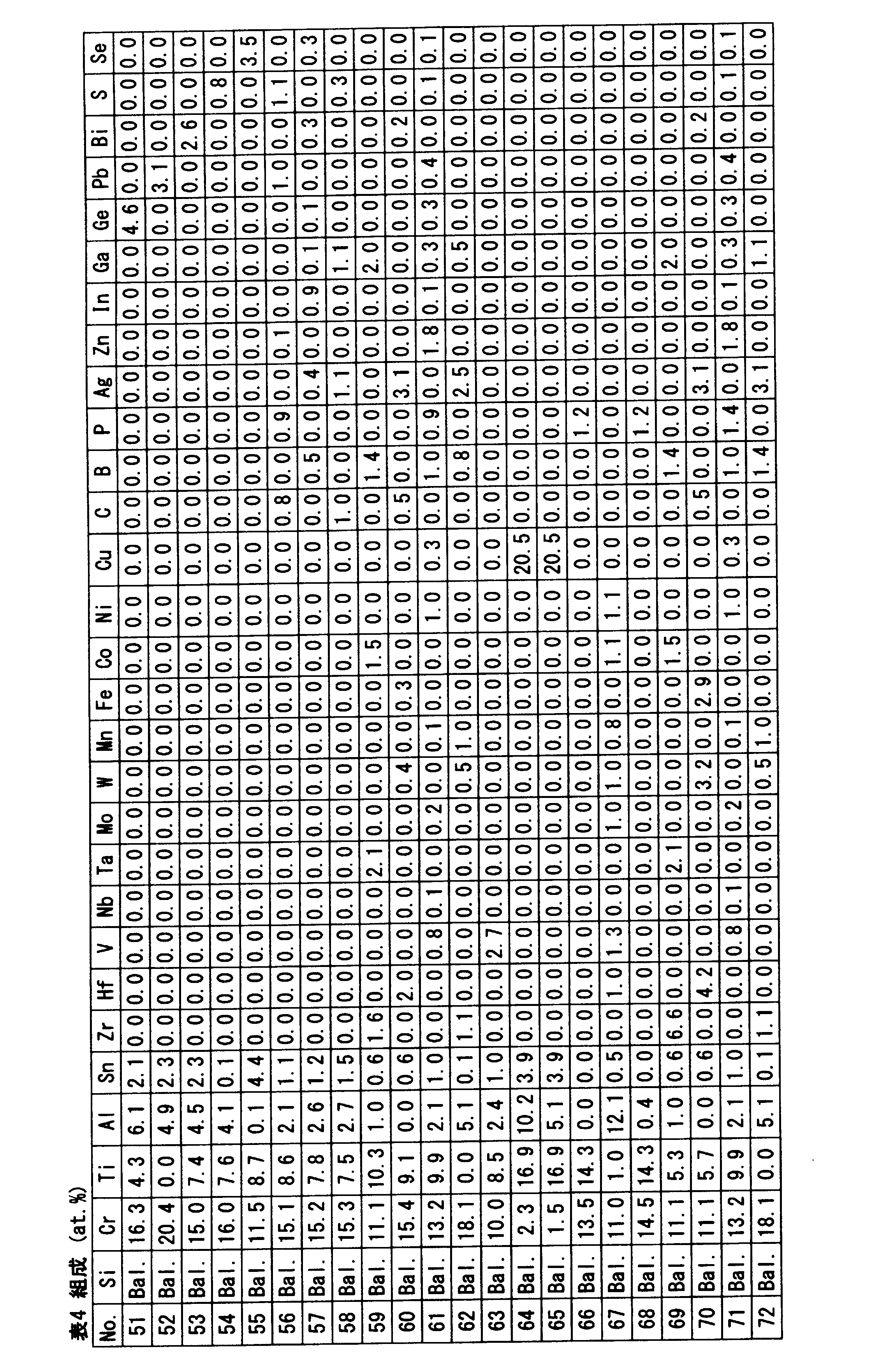
上記コイン型セルを用い、実験Aと同様にして、放電容量、容量維持率、初回クーロン効率及び負極膨張率を測定した。この結果が、下記の表5及び6に示されている。
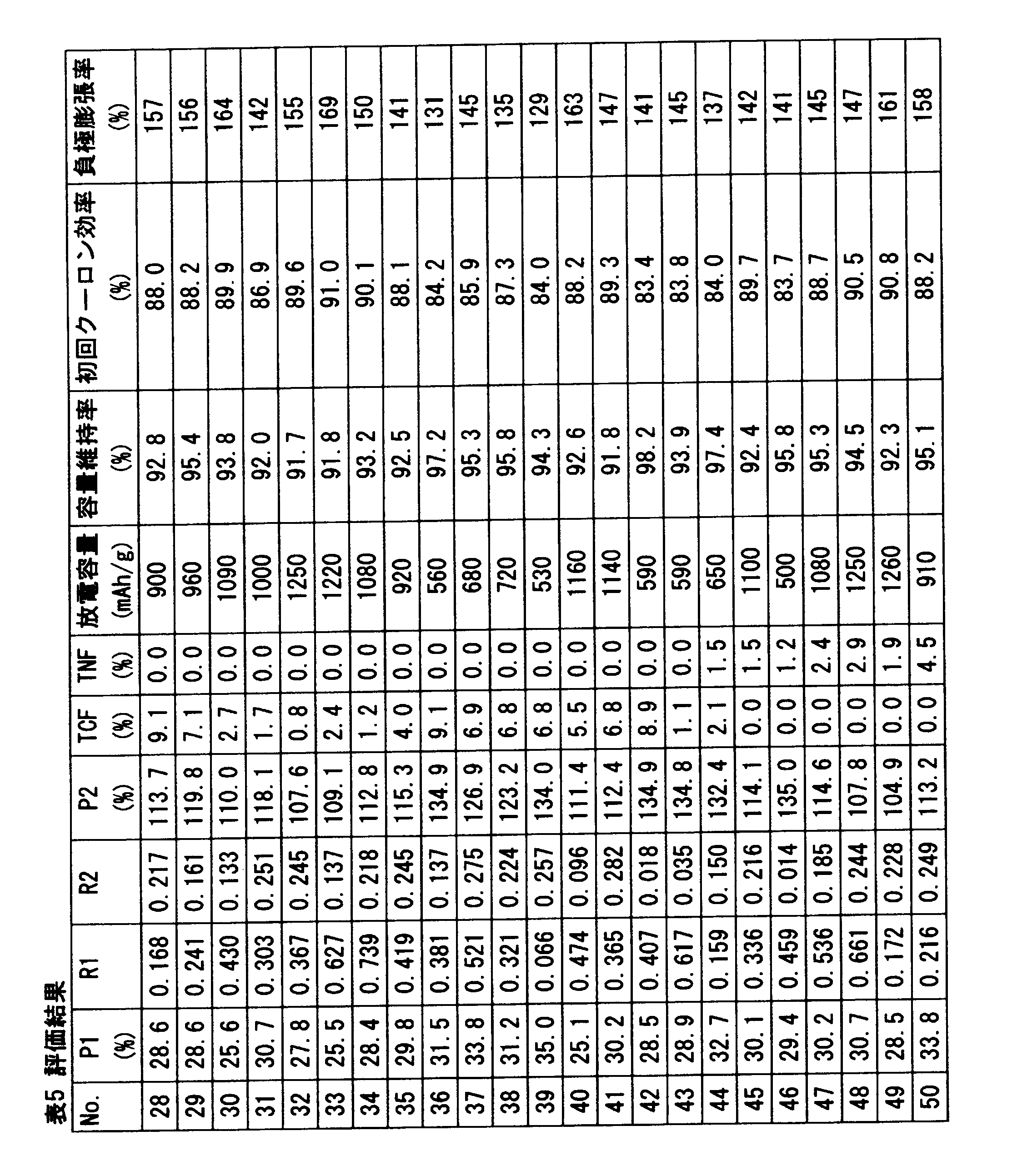
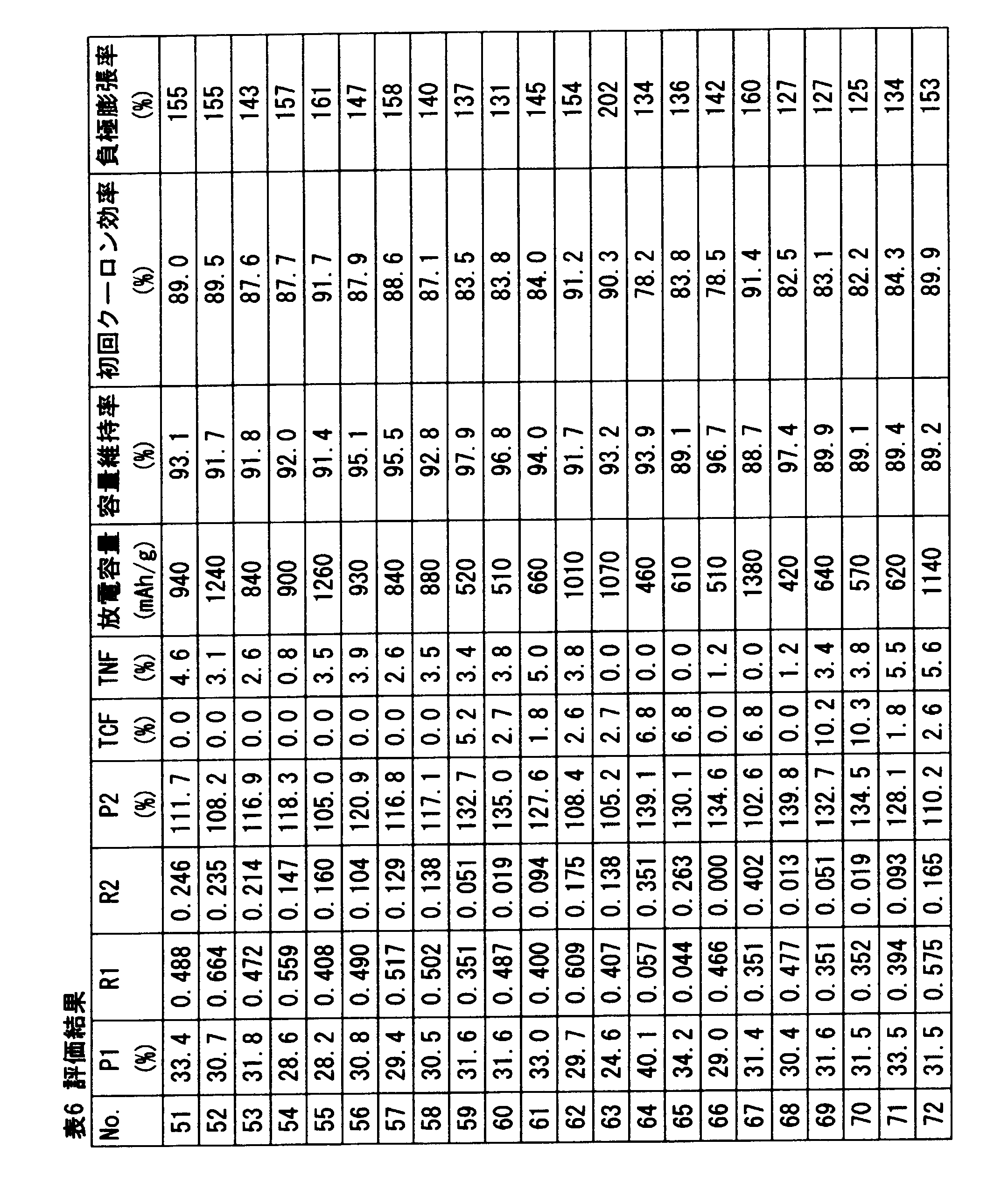
比較例63に係るセルは、比率P1の値が小さいため負極膨張率に劣る。比較例64に係るセルは、比率P1及び比率P2の値が大きいため、放電容量に劣り、かつ初回クーロン効率に劣る。比較例65に係るセルは、比R1が小さいため、容量維持率に劣る。比較例66に係るセルは、比R2が小さいため、初回クーロン効率に劣る。比較例67に係るセルは、比R2の値が大きいため、容量維持率に劣る。比較例68に係るセルは、比率P2の値が大きいため、放電容量に劣る。比較例69及び70に係るセルは、TCFの合計含有率が大きいため、容量維持率に劣る。比較例71及び72に係るセルは、TNFの合計含有率が大きいため、容量維持率が劣る。
[実験C]
[実施例73]
実験Bの実施例61と同様にして、粒径が106μm以下の粉末を得た。この粉末と、天然黒鉛粉末とを金属製容器に投入した。両粉末の質量混合比は、97/3である。この容器に、さらにクロム鋼製の硬質球を投入し、遊星ボールミル装置に装着して30時間の撹拌を行った。得られた粉末を負極用粒子とした。この粒子を用い、実験Aと同様の方法にて、コイン型セルを得た。
[実施例73]
実験Bの実施例61と同様にして、粒径が106μm以下の粉末を得た。この粉末と、天然黒鉛粉末とを金属製容器に投入した。両粉末の質量混合比は、97/3である。この容器に、さらにクロム鋼製の硬質球を投入し、遊星ボールミル装置に装着して30時間の撹拌を行った。得られた粉末を負極用粒子とした。この粒子を用い、実験Aと同様の方法にて、コイン型セルを得た。
[実施例74]
天然黒鉛粉末に代えて亜鉛粉末を用い、粉末の質量混合比を80/20とした他は実施例73と同様にして、実施例74のコイン型セルを得た。
天然黒鉛粉末に代えて亜鉛粉末を用い、粉末の質量混合比を80/20とした他は実施例73と同様にして、実施例74のコイン型セルを得た。
[実施例75]
天然黒鉛粉末に代えてSiO2の粉末を用い、粉末の質量混合比を92/8とした他は実施例73と同様にして、実施例75のコイン型セルを得た。
天然黒鉛粉末に代えてSiO2の粉末を用い、粉末の質量混合比を92/8とした他は実施例73と同様にして、実施例75のコイン型セルを得た。
上記コイン型セルを用い、実験Aと同様にして、放電容量、容量維持率、初回クーロン効率及び負極膨張率を測定した。実施例73に係るセルでは、放電容量は640mAh/gであり、容量維持率は96.2%であり、初回クーロン効率は84.2%であり、負極膨張率は142%であった。実施例74に係るセルでは、放電容量は570mAh/gであり、容量維持率は93.0%であり、初回クーロン効率は85.0%であり、負極膨張率は150%であった。さらに、実施例75に係るセルでは、放電容量は620mAh/gであり、容量維持率は94.5%であり、初回クーロン効率は81.0%であり、負極部膨張率は138%であった。実施例73~75に係るセルは、諸性能に優れている。
[考察]
実験A~Cの結果から、本発明の優位性は明らかである。
実験A~Cの結果から、本発明の優位性は明らかである。
以上説明された負極は、リチウムイオン二次電池のみならず、全固体リチウムイオン二次電池、ハイブリットキャパシタ等の蓄電デバイスにも適用されうる。
2・・・リチウムイオン二次電池
6・・・電解液
8・・・セパレータ
10・・・正極
12・・・負極
18・・・集電体
20・・・活物質層
22・・・粒子
6・・・電解液
8・・・セパレータ
10・・・正極
12・・・負極
18・・・集電体
20・・・活物質層
22・・・粒子
Claims (7)
- Si系合金からなり、
前記Si系合金が、
Cr、Al、Sn、Ti、Zr、Hf、V、Nb、Ta、Mo、W、Mn、Fe、Co、Ni、Cu、C、B、P、Ag、Zn、In、Ga、Ge、Pb、Bi、S及びSeからなる群から選択される2種以上の元素を含んでおり、残部がSi及び不可避的不純物であり、
TCF(%)が下記数式(I)で定義され、TNF(%)が下記数式(II)で定義されるとき、前記Si系合金が下記数式(1)から(6)を満たす、蓄電デバイスの負極材料。
(I)TCF%=Zr%+Hf%+V%+Nb%+Ta%+Mo%+W%+Mn%+Fe%+Co%+Ni%/2+Cu%/3
(II)TNF%=C%+B%+P%+Ag%+Zn%+In%+Ga%+Ge%+Pb%+Bi%+S%+Se%
(1)25%<Cr%+Ti%+Al%+Sn%+TCF%+TNF%≦40%
(2)0.05≦Cr%/(Cr%+Ti%+Al%+Sn%+TCF%+TNF%)
(3)0.002≦(Al%+Sn%)/(Cr%+Ti%+Al%+Sn%+TCF%+TNF%)≦0.400
(4)4.8×(Cr%+Ti%+TCF%)+(Al%+Sn%+TNF%)≦135%
(5)TCF%<10%
(6)TNF%≦5% - Si系合金と、
炭素材料、導電性金属粉末、酸化物粉末、及びセラミックス粉末から選択されるいずれか一種以上の粉末と
の複合化材料からなり、
前記Si系合金が、
Cr、Al、Sn、Ti、Zr、Hf、V、Nb、Ta、Mo、W、Mn、Fe、Co、Ni、Cu、C、B、P、Ag、Zn、In、Ga、Ge、Pb、Bi、S及びSeからなる群から選択される2種以上の元素を含んでおり、残部がSi及び不可避的不純物であり、
TCF(%)が下記数式(I)で定義され、TNF(%)が下記数式(II)で定義されるとき、前記Si系合金が下記数式(1)から(6)を満たす、蓄電デバイスの負極材料。
(I)TCF%=Zr%+Hf%+V%+Nb%+Ta%+Mo%+W%+Mn%+Fe%+Co%+Ni%/2+Cu%/3
(II)TNF%=C%+B%+P%+Ag%+Zn%+In%+Ga%+Ge%+Pb%+Bi%+S%+Se%
(1)25%<Cr%+Ti%+Al%+Sn%+TCF%+TNF%≦40%
(2)0.05≦Cr%/(Cr%+Ti%+Al%+Sn%+TCF%+TNF%)
(3)0.002≦(Al%+Sn%)/(Cr%+Ti%+Al%+Sn%+TCF%+TNF%)≦0.400
(4)4.8×(Cr%+Ti%+TCF%)+(Al%+Sn%+TNF%)≦135%
(5)TCF%<10%
(6)TNF%≦5% - 請求項1または2に記載の蓄電デバイスの負極材料の製造方法であって、前記Si系合金の溶湯を、100℃/s以上の速度で冷却して凝固させる工程を含む、製造方法。
- 請求項1に記載の蓄電デバイスの負極材料の製造方法であって、少なくとも前記Si系合金の粉末又はリボンと硬質球とを容器内で撹拌し、該Si系合金の粉末又はリボンを粉砕する工程を含む、製造方法。
- 請求項2に記載の蓄電デバイスの負極材料の製造方法であって、前記Si系合金の粉末又はリボンと、硬質球と、炭素材料、導電性金属粉末、酸化物粉末、及びセラミックス粉末から選択されるいずれか一種以上の粉末とを容器内で撹拌し、該Si系合金の粉末又はリボンを前記いずれか一種以上の粉末と複合化する工程を含む、製造方法。
- 集電体と、この集電体の表面に固着した多数の粒子とを備えており、
前記粒子が、Si系合金からなり、
前記Si系合金が、Cr、Al、Sn、Ti、Zr、Hf、V、Nb、Ta、Mo、W、Mn、Fe、Co、Ni、Cu、C、B、P、Ag、Zn、In、Ga、Ge、Pb、Bi、S及びSeからなる群から選択される2種以上の元素を含んでおり、残部がSi及び不可避的不純物であり、
TCF(%)が下記数式(I)で定義され、TNF(%)が下記数式(II)で定義されるとき、前記Si系合金が下記数式(1)から(6)を満たす、蓄電デバイスの負極。
(I)TCF%=Zr%+Hf%+V%+Nb%+Ta%+Mo%+W%+Mn%+Fe%+Co%+Ni%/2+Cu%/3
(II)TNF%=C%+B%+P%+Ag%+Zn%+In%+Ga%+Ge%+Pb%+Bi%+S%+Se%
(1)25%<Cr%+Ti%+Al%+Sn%+TCF%+TNF%≦40%
(2)0.05≦Cr%/(Cr%+Ti%+Al%+Sn%+TCF%+TNF%)
(3)0.002≦(Al%+Sn%)/(Cr%+Ti%+Al%+Sn%+TCF%+TNF%)≦0.400
(4)4.8×(Cr%+Ti%+TCF%)+(Al%+Sn%+TNF%)≦135%
(5)TCF%<10%
(6)TNF%≦5% - 正極と負極とを備えており、
前記負極が、集電体と、この集電体の表面に固着した多数の粒子とを備えており、
前記粒子が、Si系合金からなり、
前記Si系合金が、Cr、Al、Sn、Ti、Zr、Hf、V、Nb、Ta、Mo、W、Mn、Fe、Co、Ni、Cu、C、B、P、Ag、Zn、In、Ga、Ge、Pb、Bi、S及びSeからなる群から選択される2種以上の元素を含んでおり、残部がSi及び不可避的不純物であり、
TCF(%)が下記数式(I)で定義され、TNF(%)が下記数式(II)で定義されるとき、前記Si系合金が下記数式(1)から(6)を満たす、蓄電デバイス。
(I)TCF%=Zr%+Hf%+V%+Nb%+Ta%+Mo%+W%+Mn%+Fe%+Co%+Ni%/2+Cu%/3
(II)TNF%=C%+B%+P%+Ag%+Zn%+In%+Ga%+Ge%+Pb%+Bi%+S%+Se%
(1)25%<Cr%+Ti%+Al%+Sn%+TCF%+TNF%≦40%
(2)0.05≦Cr%/(Cr%+Ti%+Al%+Sn%+TCF%+TNF%)
(3)0.002≦(Al%+Sn%)/(Cr%+Ti%+Al%+Sn%+TCF%+TNF%)≦0.400
(4)4.8×(Cr%+Ti%+TCF%)+(Al%+Sn%+TNF%)≦135%
(5)TCF%<10%
(6)TNF%≦5%
Priority Applications (2)
| Application Number | Priority Date | Filing Date | Title |
|---|---|---|---|
| CN201580012018.6A CN106133955B (zh) | 2014-03-13 | 2015-03-10 | 蓄电器件的负极材料 |
| KR1020167023587A KR20160132826A (ko) | 2014-03-13 | 2015-03-10 | 축전 디바이스의 음극 재료 |
Applications Claiming Priority (2)
| Application Number | Priority Date | Filing Date | Title |
|---|---|---|---|
| JP2014050624A JP6211961B2 (ja) | 2014-03-13 | 2014-03-13 | 蓄電デバイスの負極材料 |
| JP2014-050624 | 2014-03-13 |
Publications (1)
| Publication Number | Publication Date |
|---|---|
| WO2015137338A1 true WO2015137338A1 (ja) | 2015-09-17 |
Family
ID=54071781
Family Applications (1)
| Application Number | Title | Priority Date | Filing Date |
|---|---|---|---|
| PCT/JP2015/057011 Ceased WO2015137338A1 (ja) | 2014-03-13 | 2015-03-10 | 蓄電デバイスの負極材料 |
Country Status (5)
| Country | Link |
|---|---|
| JP (1) | JP6211961B2 (ja) |
| KR (1) | KR20160132826A (ja) |
| CN (1) | CN106133955B (ja) |
| TW (1) | TWI639268B (ja) |
| WO (1) | WO2015137338A1 (ja) |
Cited By (1)
| Publication number | Priority date | Publication date | Assignee | Title |
|---|---|---|---|---|
| WO2018193864A1 (ja) * | 2017-04-17 | 2018-10-25 | 山陽特殊製鋼株式会社 | 蓄電デバイス用負極材料 |
Families Citing this family (9)
| Publication number | Priority date | Publication date | Assignee | Title |
|---|---|---|---|---|
| EP2995335B1 (en) * | 2014-09-11 | 2022-10-12 | Pine Medical Limited | Drug coated balloon catheter and method of manufacture thereof |
| US10340519B2 (en) | 2015-11-10 | 2019-07-02 | Nissan Motor Co., Ltd. | Negative electrode active material for electric device and electric device using the same |
| JP6743503B2 (ja) * | 2016-06-16 | 2020-08-19 | 日産自動車株式会社 | 電気デバイス用負極活物質、およびこれを用いた電気デバイス |
| JP6705302B2 (ja) * | 2016-06-16 | 2020-06-03 | 日産自動車株式会社 | 電気デバイス用負極活物質、およびこれを用いた電気デバイス |
| JP6789138B2 (ja) * | 2017-01-30 | 2020-11-25 | 京セラ株式会社 | 蓄電池用負極材料、蓄電池用負極および蓄電池 |
| CN107723612A (zh) * | 2017-10-20 | 2018-02-23 | 苏州市天星山精密模具有限公司 | 一种耐冲击抗氧化注塑模具 |
| CN112823069A (zh) * | 2018-10-05 | 2021-05-18 | 住友化学株式会社 | 金属粒子组合物的制造方法及金属粒子组合物 |
| CN110380015B (zh) * | 2019-05-27 | 2020-09-29 | 合山市华美新能源科技有限公司 | 锂电池正极浆料的制备方法 |
| JP7694598B2 (ja) * | 2023-03-27 | 2025-06-18 | 株式会社豊田中央研究所 | 多孔質シリコン材料、蓄電デバイス及び多孔質シリコン材料の製造方法 |
Citations (2)
| Publication number | Priority date | Publication date | Assignee | Title |
|---|---|---|---|---|
| JP2010108945A (ja) * | 1998-05-13 | 2010-05-13 | Ube Ind Ltd | 非水二次電池 |
| JP2012156028A (ja) * | 2011-01-27 | 2012-08-16 | Idemitsu Kosan Co Ltd | アモルファス合金、それからなる二次電池用負極材料、それを含む二次電池用負極、及び二次電池 |
Family Cites Families (10)
| Publication number | Priority date | Publication date | Assignee | Title |
|---|---|---|---|---|
| JP2001297757A (ja) | 2000-04-14 | 2001-10-26 | Sumitomo Metal Ind Ltd | 非水電解質二次電池用負極材料およびその製造方法 |
| JP5245425B2 (ja) * | 2007-06-05 | 2013-07-24 | ソニー株式会社 | 負極および二次電池 |
| CN101643864B (zh) * | 2009-07-10 | 2011-06-15 | 成都中科来方能源科技有限公司 | 多元硅合金/碳复合材料及其制备方法和用途 |
| JP5362502B2 (ja) * | 2009-09-24 | 2013-12-11 | 山陽特殊製鋼株式会社 | リチウム二次電池負極物質用Si合金 |
| JP2012113945A (ja) | 2010-11-24 | 2012-06-14 | Daido Steel Co Ltd | リチウムイオン電池用負極材料及びその製造方法 |
| JP5766445B2 (ja) | 2011-01-17 | 2015-08-19 | 山陽特殊製鋼株式会社 | リチウムイオン二次電池負極用Si合金粉末およびその製造方法 |
| JP2012178344A (ja) * | 2011-02-02 | 2012-09-13 | Hitachi Chem Co Ltd | 複合材料、その製造方法、リチウムイオン二次電池用負極、及びリチウムイオン二次電池 |
| JP5884573B2 (ja) | 2011-09-30 | 2016-03-15 | 大同特殊鋼株式会社 | リチウムイオン電池用負極活物質及びこれを用いたリチウムイオン電池用負極 |
| JP6322362B2 (ja) * | 2012-02-01 | 2018-05-09 | 山陽特殊製鋼株式会社 | Si系合金負極材料 |
| JP2013191529A (ja) | 2012-02-16 | 2013-09-26 | Hitachi Chemical Co Ltd | 複合材料、複合材料の製造方法、リチウムイオン二次電池用電極材料、リチウムイオン二次電池用負極、及びリチウムイオン二次電池 |
-
2014
- 2014-03-13 JP JP2014050624A patent/JP6211961B2/ja not_active Expired - Fee Related
-
2015
- 2015-03-10 KR KR1020167023587A patent/KR20160132826A/ko not_active Withdrawn
- 2015-03-10 WO PCT/JP2015/057011 patent/WO2015137338A1/ja not_active Ceased
- 2015-03-10 CN CN201580012018.6A patent/CN106133955B/zh active Active
- 2015-03-12 TW TW104107920A patent/TWI639268B/zh active
Patent Citations (2)
| Publication number | Priority date | Publication date | Assignee | Title |
|---|---|---|---|---|
| JP2010108945A (ja) * | 1998-05-13 | 2010-05-13 | Ube Ind Ltd | 非水二次電池 |
| JP2012156028A (ja) * | 2011-01-27 | 2012-08-16 | Idemitsu Kosan Co Ltd | アモルファス合金、それからなる二次電池用負極材料、それを含む二次電池用負極、及び二次電池 |
Cited By (1)
| Publication number | Priority date | Publication date | Assignee | Title |
|---|---|---|---|---|
| WO2018193864A1 (ja) * | 2017-04-17 | 2018-10-25 | 山陽特殊製鋼株式会社 | 蓄電デバイス用負極材料 |
Also Published As
| Publication number | Publication date |
|---|---|
| JP6211961B2 (ja) | 2017-10-11 |
| CN106133955A (zh) | 2016-11-16 |
| JP2015176676A (ja) | 2015-10-05 |
| TWI639268B (zh) | 2018-10-21 |
| TW201547092A (zh) | 2015-12-16 |
| CN106133955B (zh) | 2019-04-26 |
| KR20160132826A (ko) | 2016-11-21 |
Similar Documents
| Publication | Publication Date | Title |
|---|---|---|
| JP6211961B2 (ja) | 蓄電デバイスの負極材料 | |
| JP6322362B2 (ja) | Si系合金負極材料 | |
| KR20170131239A (ko) | 리튬 이차전지용 음극재 | |
| WO2012144424A1 (ja) | Si系合金負極材料 | |
| CN106104863A (zh) | 蓄电器件的负极材料 | |
| TWI446613B (zh) | 基於Si之負極材料 | |
| TWI635645B (zh) | Si-based eutectic alloy for negative electrode active material of power storage device and method for producing same | |
| JP6076772B2 (ja) | 蓄電デバイス用Si系合金負極材料およびそれを用いた電極 | |
| WO2016043061A1 (ja) | 蓄電デバイス用Si系合金負極材料およびそれを用いた電極 | |
| KR102129913B1 (ko) | 축전디바이스용 음극재료 | |
| WO2012008540A1 (ja) | 電気伝導性に優れたSi系合金負極材料およびその製造方法 | |
| JP6371635B2 (ja) | 蓄電デバイス用Si系合金負極材料およびそれを用いた電極 | |
| CN105917498A (zh) | 用于锂二次电池的阴极活性物质 | |
| JP6630632B2 (ja) | 蓄電デバイス用負極材料 | |
| JP2018181660A (ja) | 蓄電デバイス用負極材料 |
Legal Events
| Date | Code | Title | Description |
|---|---|---|---|
| 121 | Ep: the epo has been informed by wipo that ep was designated in this application |
Ref document number: 15761856 Country of ref document: EP Kind code of ref document: A1 |
|
| ENP | Entry into the national phase |
Ref document number: 20167023587 Country of ref document: KR Kind code of ref document: A |
|
| NENP | Non-entry into the national phase |
Ref country code: DE |
|
| 122 | Ep: pct application non-entry in european phase |
Ref document number: 15761856 Country of ref document: EP Kind code of ref document: A1 |