WO2015133111A1 - 直線形鋼矢板、該直線形鋼矢板を用いた構造物の補強構造及び補強方法 - Google Patents
直線形鋼矢板、該直線形鋼矢板を用いた構造物の補強構造及び補強方法 Download PDFInfo
- Publication number
- WO2015133111A1 WO2015133111A1 PCT/JP2015/001071 JP2015001071W WO2015133111A1 WO 2015133111 A1 WO2015133111 A1 WO 2015133111A1 JP 2015001071 W JP2015001071 W JP 2015001071W WO 2015133111 A1 WO2015133111 A1 WO 2015133111A1
- Authority
- WO
- WIPO (PCT)
- Prior art keywords
- sheet pile
- steel sheet
- thickness
- claw
- joint
- Prior art date
- Legal status (The legal status is an assumption and is not a legal conclusion. Google has not performed a legal analysis and makes no representation as to the accuracy of the status listed.)
- Ceased
Links
Images


Classifications
-
- E—FIXED CONSTRUCTIONS
- E02—HYDRAULIC ENGINEERING; FOUNDATIONS; SOIL SHIFTING
- E02D—FOUNDATIONS; EXCAVATIONS; EMBANKMENTS; UNDERGROUND OR UNDERWATER STRUCTURES
- E02D5/00—Bulkheads, piles, or other structural elements specially adapted to foundation engineering
- E02D5/02—Sheet piles or sheet pile bulkheads
- E02D5/03—Prefabricated parts, e.g. composite sheet piles
- E02D5/04—Prefabricated parts, e.g. composite sheet piles made of steel
- E02D5/08—Locking forms; Edge joints; Pile crossings; Branch pieces
Definitions
- the present invention relates to a straight steel sheet pile (straight web-type sheet piles), a reinforcing structure and a reinforcing method for a structure using the straight steel sheet pile.
- a straight steel sheet pile is connected to a circular or elliptical shape by fitting joints at both ends, and is used as a closed wall structure for a reinforcing structure of a structure.
- a structural reinforcement method to surround an existing structure, a linear steel sheet pile is placed around it to form an outer wall, and filled concrete is poured into the gap between the linear steel sheet pile and the existing structure, There is a “winding-up reinforcement construction method” (see Patent Document 1).
- a shape of the linear steel sheet pile used for reinforcement there exist FL type and FXL type (refer nonpatent literature 1).
- the linear steel sheet pile 50 includes a joint part 51 including a main claw part 51 a and a sub claw part 51 b and a web part 52 that connects the joint parts 51 to each other.
- the distance from the center of the web portion 52 (the center position is indicated by a one-dot chain line in FIG. 5) to the outermost edge of the sub claw portion 51b is referred to as an effective height h.
- FIGS. 6 to 8 are diagrams disclosed in Patent Document 1.
- FIG. 6, 53 is an existing structure (bridge pier in Patent Document 1), 55 is footing, 57 is a ground surface, and 59 and FIG. 8 are filled concrete (solidified in Patent Document 1).
- Material 61, 61 is a reinforcing bar (61a is a main reinforcement, 61b is a hoop bar).
- the existing structure 53 and the steel sheet pile wall are brought as close as possible, so that the construction site area (construction site) Aimed to reduce area).
- a reinforcing reinforcing bar 61 may be further arranged between the existing structure 53 and the steel sheet pile wall. In this case, a gap between the joint portion of the linear steel sheet pile 50 and the reinforcing reinforcing bar 61 may be provided.
- the proximity distance (near distance B) between the existing structure 53 and the steel sheet pile wall is about 200 mm.
- a cover thickness k up to the reinforcing reinforcing bar 61 is required to be 70 mm or more in order to ensure quality. Therefore, the distance from the existing structure 53 to the reinforcing steel bar 61 is 70 mm at the minimum.
- the main reinforcing bar diameter d1 is defined as a minimum of 16 mm and the strip reinforcing bar diameter d2 is defined as a minimum of 13 mm.
- the shape of the linear steel sheet pile 50 used at present is FL type and FXL type (see Non-Patent Document 1), and the effective heights h are 44.5 mm and 47.0 mm, respectively.
- the gap S is smaller than the normal maximum concrete aggregate diameter of 20 mm. From the above, there is a concern that the concrete aggregate will be caught.
- the joint shape (height) of the steel sheet pile can be reduced to the above problem, the gap between the joint part of the linear steel sheet pile and the reinforcing reinforcing bar can be widened, and the problem of catching the concrete aggregate is solved. Is done.
- the structural bearing force is improved mainly by the restraint effect by the sheet pile wall.
- the important part that produces the circumferential surface restraint force of the steel sheet pile wall is the joint part of the steel sheet pile, the tensile bearing force (tensile bearing force) of the joint fitting part where the joint part and the joint part are fitted If it falls, it came to the idea that the peripheral surface restraint force of a steel sheet pile wall will also fall simultaneously.
- the present invention has been made in order to solve the above-described problems.
- the joint shape (height) of the steel sheet pile is made as small as possible so that the workability and structural reliability during filling concrete (structural reliability) ), And a reinforcing structure and a reinforcing method using the linear steel sheet pile in which the tensile strength of the joint fitting portion does not decrease.
- a linear steel sheet pile according to the present invention is a linear steel sheet pile having joint parts composed of main claws (main-claw) and sub-claws (sub-claw) at both ends,
- the main claw height g of the joint is 6.0 mm or more
- the ratio f3 / f1 of the main claw thickness f3 to the web part thickness f1 is 0.82 or more
- the ratio f2 / f1 of the sub claw thickness f2 to the web part thickness f1 is 1.16 or more.
- the ratio c / f3 between the opening height c and the main claw thickness f3 is 1.25 or more, and the distance h (effective height) from the center position of the web portion to the outermost edge of the sub claw portion is 40 mm or less. It is characterized by being.
- the linear steel sheet pile which concerns on this invention is a linear steel sheet pile which has the joint part which consists of a main nail
- the main claw height g of the joint is 6.0 mm or more
- the ratio f3 / f1 of the main claw thickness f3 to the web part thickness f1 is 0.82 or more
- the ratio f2 / f1 of the sub claw thickness f2 to the web part thickness f1 is 1.16 or more.
- the ratio c / f3 between the opening height c and the main claw thickness f3 is 1.25 or more, and the distance h (effective height) from the center position of the web portion to the outermost edge of the sub claw portion is 37 mm or less. It is what.
- the reinforcing structure for a structure according to the present invention is a reinforcing structure for a structure that is reinforced by surrounding a structure with a linear steel sheet pile, and is described in (1) or (2) above.
- a linear steel sheet pile surrounds the structure so that the proximity distance between the structure and the linear steel sheet pile wall is 200 mm or less, and reinforcing steel bars are provided in the gap between the linear steel sheet pile and the structure. And is filled with a solidifying material.
- the reinforcement method of the structure which concerns on this invention is a reinforcement method of the structure which encloses the periphery of a structure with a linear steel sheet pile, Comprising: Said (1) or (2) description Surrounding the structure with a linear steel sheet pile so that the proximity distance between the structure and the linear steel sheet pile wall is 200 mm or less, and between the linear steel sheet pile and the structure
- the method includes a step of removing earth and sand, and a step of disposing reinforcing reinforcing bars in a gap between the linear steel sheet pile and the structure and filling a solidified material.
- the main claw height g of the joint is 6.0 mm or more
- the ratio f3 / f1 of the main claw thickness f3 to the web part thickness f1 is 0.82 or more
- the ratio f2 / f1 is 1.16 or more
- the ratio c / f3 of the joint opening height c to the main claw thickness f3 is 1.25 or more
- the effective height h is 40 mm or less. Since the joint shape can be reduced while maintaining the workability, the economy can be improved.
- the effective height h of the joint portion is 40 mm or less, the gap S (see FIG. 2) from the linear steel sheet pile to the reinforcing bar is widened, and the catch of the concrete aggregate can be eliminated.
- FIG. 1 is an enlarged view of the joint portion 3 when the standing state of the linear steel sheet pile 1 is viewed in plan.
- the linear steel sheet pile 1 has the joint part 3 which consists of the main nail
- g is the main claw height
- f1 is the web plate thickness
- f2 is the sub claw thickness
- f3 is the main claw thickness
- c is the joint opening height
- h is the effective height.
- the main nail height g refers to the nail height at a portion (main nail deepest portion) where the nail depth in the main nail portion 3a is deepest in the height direction.
- the sub nail thickness f2 is a thickness at a portion (sub nail deepest portion) where the nail depth in the sub nail portion 3b is deepest in the height direction, more specifically, the sub nail deepest portion and the sub nail portion. The distance of the outermost edge.
- the main claw thickness f3 is the thickness at the deepest portion of the main claw of the main claw portion 3a.
- the main claw height g of the joint is 6.0 mm or more
- the ratio f3 / f1 of the main claw thickness f3 to the web part thickness f1 is 0.82 or more
- the sub claw thickness f2 and the web part plate The ratio f2 / f1 of the thickness f1 is 1.16 or more
- the ratio c / f3 of the joint opening height c to the main claw thickness f3 is 1.25 or more
- the effective height h is 40 mm or less or 37 mm or less.
- FIG. 2 illustrates a part of the reinforcing structure 7 (hereinafter simply referred to as “reinforcing structure 7”) of the existing structure 53 using the linear steel sheet pile 1. 2 that are the same as those in FIG. 8 are given the same reference numerals, and descriptions thereof are omitted.
- the reinforcing structure 7 shown in FIG. 2 is premised on the proximity distance B being 200 mm or less, and the covering thickness k, the main reinforcing bar diameter d1, and the strip reinforcing bar diameter d2 are the same as those in FIG. Details of the reinforcing structure 7 will be described in the second embodiment.
- the effective height h of the joint portion be 37 mm or less (knowledge (ii)).
- the effective height h of the joint portion needs to be 40 mm or less, and in some cases 37 mm or less.
- the effective height h is desirably larger than 30 mm from the viewpoint of securing the strength of the joint fitting portion.
- FIG. 3 shows the load transmission mechanism in the joint fitting portion, and shows the stress distribution (contour display).
- the same components as those in FIG. 3 it has shown that a stress is so high that the part with a light color is outline.
- T1 Yield tensile load of web part 5 (per unit depth)
- f1 Web sheet thickness
- ⁇ y Material strength of straight steel sheet pile 1 (Tensile yield stress)
- the joint fitting portion has two contact portions P2 and P3, and the tensile force acting on the web portion 5 is divided into two component forces (component force) of the sub claw portion 3b and the main claw portion 3a. ).
- T1 T2 + T3
- T2 Tensile load component acting on the secondary nail (per unit depth)
- T3 Tensile load component force acting on the main nail (per unit depth)
- each component force in the above equation can be expressed by the following equation.
- T2 ⁇ X2 (f2) 2/6 ⁇ ⁇ y
- T3 ⁇ X3 (f3) 2/6 ⁇ ⁇ y
- X2 Distance from the web center axis to the secondary nail component force acting point
- X3 Distance from the web center axis to the main nail component force acting point (average)
- f2 Subnail thickness
- f3 Main nail thickness
- the effective contact height can be evaluated by multiplying the main nail height g by the sine sin ⁇ of the contact angle ⁇ (see the following formula). Therefore, in order to increase the load transmission capability at the contact portion P3, it is important to ensure the main claw height g of the joint.
- F g ⁇ ⁇ y ⁇ sin ⁇ Where ⁇ is the angle formed between the central axis of the web portion and the tangent L at the contact portion P3 (contact angle).
- the main claw height g should be about 12.0 mm.
- the joint fitting part will approach the one-point contact structure from the conventional two-point contact structure and become an unstable structure. It is necessary to secure. That is, it is considered necessary to ensure the sub claw thickness f2 to be equal to or greater than a predetermined value with respect to the web portion plate thickness f1. In view of this point and analysis, etc., f2 / f1 must be 1.16 or more in order to prevent premature plastic bending deformation (ductile bending deformation) in the sub-nail and the joint fitting strength from falling below a predetermined value. We obtained the knowledge that there was (knowledge (v)).
- the joint opening height c needs to have an appropriate margin with respect to the main claw thickness f3.
- c / f3 must be 1.25 or more in order to prevent joint fitting resistance increase due to steel sheet pile elastic deformation during construction (knowledge ( vi)).
- the joint opening height c is larger than the sum of the main claw thickness f3 and the main claw height g, it is necessary to be careful because the risk of the joint coming off increases.
- the main claw height g is 6.0 mm or more
- the ratio f3 / f1 between the main claw thickness f3 and the web part plate thickness f1 is 0.82 or more
- the ratio c / f3 of joint opening height c to main claw thickness f3 is 1.25 or more
- the effective height h is 40 mm or less or 37 mm or less. While maintaining, the joint shape can be made small, and this can improve the economy.
- the strength of the joint fitting portion is demonstrated in Example 1.
- the effective height h of the joint portion is 40 mm or less, as shown in FIG. 2, in the reinforcing structure 7 using the linear steel sheet pile 1, the clearance S from the linear steel sheet pile 1 to the reinforcing bar is provided.
- the concrete can be expanded more than the conventional one, and the filled concrete can be poured into the gap S without being caught by the concrete aggregate, so that no gap (weak spot) is generated.
- the reinforcement structure 7 will be described in the second embodiment.
- the reinforcing structure 7 of the existing structure 53 according to the second embodiment has a proximity distance B between the existing structure 53 and the steel sheet pile wall by the linear steel sheet pile 1 shown in the first embodiment.
- reinforcing steel bars 61 are arranged in the gap between the linear steel sheet pile 1 and the existing structure 53, and filled concrete 59 as a solidifying material is filled. It is a feature.
- illustration of the filling concrete 59 is abbreviate
- the specific example of the reinforcement structure using the linear steel sheet pile 1 is demonstrated in Example 2.
- the reinforcing structure 7 uses the linear steel sheet pile 1 of the first embodiment, and can improve the workability at the time of placing the filled concrete, and the tensile strength of the joint fitting portion can be improved. Since it does not decrease, the circumferential surface restraint force of the steel sheet pile wall does not decrease, and the structural reliability can be ensured.
- the reinforcement structure 7 of the existing structure 53 can be constructed
- a method of reinforcing an existing structure 53 comprising the step of: arranging reinforcing reinforcing bars 61 in a gap between the reinforcing bars 61 and filling filled concrete 59 as a solidifying material.
- the experiment is to obtain the tensile strength of joint fitting for the current FL type and the steel sheet pile (including the present invention) whose cross-sectional shape is changed by structural analysis by FEM.
- FIG. 4 shows an analysis model.
- the material strength characteristics were a bilinear type with a Young's modulus of 205,000 N / mm 2 , the material yield strength was 295 N / mm 2 , and the material tensile strength was 450 N / mm 2 (specified lower limit of steel sheet pile material SY295).
- the cross-sectional shape was changed using the effective height h of the joint part, the main claw height g of the joint, the web plate thickness f1, the sub claw thickness f2, the main claw thickness f3, and the joint opening height c as analysis parameters.
- the above analysis parameters were set so as to be within the scope of the present invention.
- the main claw height g of the joint is 6.0 mm or more
- the ratio f3 / f1 between the main claw thickness f3 and the web part thickness f1 is 0.82 or more
- the ratio between the sub claw thickness f2 and the web part thickness f1 is f2 / f1.
- the ratio c / f3 of the joint opening height c to the main claw thickness f3 is 1.25 or more
- the effective height h is 40 mm or less.
- Comparative Examples 1 to 3 were set so that any of the above analysis parameters was outside the scope of the present invention. Specifically, Comparative Example 1 has a main claw height g of 5.5 mm (not 6.0 mm or more), Comparative Example 2 has an f3 / f1 of 0.74 (not 0.82 or more), and Comparative Example 3 has an f2 / f1 of 1.11 (1.16 or more). Not). Table 1 shows a summary of analysis parameters and analysis results.
- Example 1 of the present invention has a joint fitting portion tensile strength comparable to that of the current FL type.
- the present invention example 2 the present invention example 3 and the present invention example 4, although the strength is slightly lower than the current FL type joint fitting part tensile strength, the strength exceeding the standard tensile strength of the joint fitting part 3.92MN / m Is obtained, which is preferable.
- Comparative Examples 1 to 3 and Comparative Examples 7 and 8 the results were below the standard tensile strength.
- the joint shape is small, the main claw thickness f3, the sub claw thickness f2, and the joint opening height c are well-balanced load transmission capacity (strength). ) was obtained, it was proved that the strength of the joint fitting portion was higher than the standard tensile strength.
- the covering thickness k was 70 mm
- the main reinforcing bar diameter d1 was 16 mm
- the strip reinforcing bar diameter d2 was 13 mm.
- the gap S from the linear steel sheet pile 1 to the reinforcing bar was set to 20 mm.
- Table 2 summarizes the correspondence between the effective height h of the joint and the proximity distance B under the above conditions.
- the proximity distance B could be 200 mm or less.
- the proximity distance B could be 200 mm or less.
Landscapes
- Engineering & Computer Science (AREA)
- Structural Engineering (AREA)
- Chemical & Material Sciences (AREA)
- Composite Materials (AREA)
- Life Sciences & Earth Sciences (AREA)
- General Life Sciences & Earth Sciences (AREA)
- Mining & Mineral Resources (AREA)
- Paleontology (AREA)
- Civil Engineering (AREA)
- General Engineering & Computer Science (AREA)
- Bulkheads Adapted To Foundation Construction (AREA)
- Metal Rolling (AREA)
Abstract
本発明に係る直線形鋼矢板1は、継手の主爪高gが6.0mm以上、主爪厚f3とウェブ部板厚f1の比f3/f1が0.82以上、副爪厚f2とウェブ部板厚f1の比f2/f1が1.16以上、継手開口高さcと主爪厚f3との比c/f3が1.25以上であり、ウェブ部5の中心位置から副爪部3bの最外縁までの距離h(有効高さ)が40mm以下であることを特徴とするものである。
Description
本発明は、直線形鋼矢板(straight web-type sheet piles)、該直線形鋼矢板を用いた構造物の補強構造及び補強方法に関する。
通常、直線形鋼矢板は、両端の継手(joint)を嵌合させ(fit)円形もしくは楕円形状に繋げられ、閉じた壁構造として構造物の補強構造に用いられる。
構造物の補強工法の一例として、既存構造物を取り巻くように、周囲に直線形鋼矢板を打設して外壁を形成し、直線形鋼矢板と既存構造物との隙間に充填コンクリートを流し込み、一体化させて強化する「巻き立て補強工法」(winding-up reinforcement construction method)がある(特許文献1参照)。
また、補強に用いられる直線形鋼矢板の形状としては、FL型、FXL型がある(非特許文献1参照)。
構造物の補強工法の一例として、既存構造物を取り巻くように、周囲に直線形鋼矢板を打設して外壁を形成し、直線形鋼矢板と既存構造物との隙間に充填コンクリートを流し込み、一体化させて強化する「巻き立て補強工法」(winding-up reinforcement construction method)がある(特許文献1参照)。
また、補強に用いられる直線形鋼矢板の形状としては、FL型、FXL型がある(非特許文献1参照)。
鋼管杭協会:鋼矢板 設計から施工まで、pp.337-338、2007
発明が解決しようとする課題を説明するのに先立って、一般的な直線形鋼矢板の継手部の形状を図5に基づいて説明する。
図5に示す通り、直線形鋼矢板50は、主爪部51aと副爪部51bからなる継手部51と、継手部51同士を繋ぐウェブ部52とを有している。本明細書においては、ウェブ部52の中心(中心位置を図5中に一点鎖線で示す)から副爪部51bの最外縁までの距離を有効高さhと呼ぶ。
図5に示す通り、直線形鋼矢板50は、主爪部51aと副爪部51bからなる継手部51と、継手部51同士を繋ぐウェブ部52とを有している。本明細書においては、ウェブ部52の中心(中心位置を図5中に一点鎖線で示す)から副爪部51bの最外縁までの距離を有効高さhと呼ぶ。
次に、図6~図8に基づいて本発明が解決しようとする課題について説明する。なお、図6~図8は、特許文献1において開示された図である。
図6において、53は既存構造物(特許文献1中では橋脚)、55はフーチング(footing)、57は地面(ground surface)、図7及び図8において59は充填コンクリート(特許文献1中では固化材)、61は補強鉄筋(reinforcing bar)(61aが主鉄筋(main reinforcement)、61bが帯鉄筋(hoop bar))を示している。
図6において、53は既存構造物(特許文献1中では橋脚)、55はフーチング(footing)、57は地面(ground surface)、図7及び図8において59は充填コンクリート(特許文献1中では固化材)、61は補強鉄筋(reinforcing bar)(61aが主鉄筋(main reinforcement)、61bが帯鉄筋(hoop bar))を示している。
前述の「巻き立て補強工法」(図6参照)では、既存構造物53と鋼矢板壁(直線形鋼矢板50で形成される鋼矢板壁)を極力近接させることで、施工敷地面積(construction site area)を小さくすることを志向している。
しかし、図7に示すように、既存構造物53と鋼矢板壁の間において、さらに補強鉄筋61を配置する場合があり、この場合、直線形鋼矢板50の継手箇所と補強鉄筋61との隙間が狭いことから、隙間に充填コンクリート59を流し込む際、コンクリート骨材(aggregate for concrete)(最大径20mm程度)が引っ掛かり、コンクリートが充填されず空隙(弱点箇所)が生じることが懸念される。
この点について、以下に図8に基づいて具体的に説明する。
しかし、図7に示すように、既存構造物53と鋼矢板壁の間において、さらに補強鉄筋61を配置する場合があり、この場合、直線形鋼矢板50の継手箇所と補強鉄筋61との隙間が狭いことから、隙間に充填コンクリート59を流し込む際、コンクリート骨材(aggregate for concrete)(最大径20mm程度)が引っ掛かり、コンクリートが充填されず空隙(弱点箇所)が生じることが懸念される。
この点について、以下に図8に基づいて具体的に説明する。
特許文献1においては、既存構造物53と鋼矢板壁との近接距離(近接距離B)(near distance B)は200mm程度とされている。
さらに、道路橋示方書(specifications for highway bridges)などによれば、品質確保のため、補強鉄筋61までの被り厚k(cover thickness k)は70mm以上必要とされている。従って、既存構造物53から補強鉄筋61までの距離は最小で70mmとなる。また、同様に品質確保の面から主鉄筋径d1は最小で16mm、帯鉄筋径d2は最小で13mmと規定されている。
さらに、道路橋示方書(specifications for highway bridges)などによれば、品質確保のため、補強鉄筋61までの被り厚k(cover thickness k)は70mm以上必要とされている。従って、既存構造物53から補強鉄筋61までの距離は最小で70mmとなる。また、同様に品質確保の面から主鉄筋径d1は最小で16mm、帯鉄筋径d2は最小で13mmと規定されている。
一方、現状、用いられる直線形鋼矢板50の形状としては、FL型、FXL型であり(非特許文献1参照)、有効高さhは、それぞれ44.5mm、47.0mmである。鋼矢板の全高さ(h×2)は、例えばFL型では89mmである。
従って、FL型を用いた補強構造においては、直線形鋼矢板50から補強鉄筋61までの隙間(最小部)SはS=B-k-d1-d2-(h×2)=200-70-16-13-89=12mmとなる。このように、継手部51の有効高さhが最も小さいFL型を用いても、隙間Sは通常のコンクリート最大骨材径20mmよりも小さい。
以上のことから、コンクリート骨材が引っ掛かることが懸念されるのである。
従って、FL型を用いた補強構造においては、直線形鋼矢板50から補強鉄筋61までの隙間(最小部)SはS=B-k-d1-d2-(h×2)=200-70-16-13-89=12mmとなる。このように、継手部51の有効高さhが最も小さいFL型を用いても、隙間Sは通常のコンクリート最大骨材径20mmよりも小さい。
以上のことから、コンクリート骨材が引っ掛かることが懸念されるのである。
上記の問題に対し、鋼矢板の継手形状(高さ)を小さくすることができれば、直線形鋼矢板の継手箇所と補強鉄筋との隙間を広げることができ、コンクリート骨材の引っ掛かりの問題が解消される。
しかしながら、ただ単に鋼矢板の継手形状を小さくすると継手嵌合部の強度が低下するという問題がある。
直線形鋼矢板を用いた補強構造では、主として鋼矢板壁面の拘束力(restraint effect by sheet pile wall)により構造耐力(structural bearing force)が向上することとなる。そして、発明者らは、鋼矢板壁の周面拘束力を生み出す重要部位は鋼矢板の継手部であり、継手部と継手部が嵌合した継手嵌合部の引張り耐力(tensile bearing force)が低下すれば、鋼矢板壁の周面拘束力も同時に低下することになることに想到した。
しかしながら、ただ単に鋼矢板の継手形状を小さくすると継手嵌合部の強度が低下するという問題がある。
直線形鋼矢板を用いた補強構造では、主として鋼矢板壁面の拘束力(restraint effect by sheet pile wall)により構造耐力(structural bearing force)が向上することとなる。そして、発明者らは、鋼矢板壁の周面拘束力を生み出す重要部位は鋼矢板の継手部であり、継手部と継手部が嵌合した継手嵌合部の引張り耐力(tensile bearing force)が低下すれば、鋼矢板壁の周面拘束力も同時に低下することになることに想到した。
本発明は、上記のような課題を解決するためになされたものであり、鋼矢板の継手形状(高さ)を極力小さくして、充填コンクリート打設時の施工性および構造信頼性(structural reliability)を向上させるとともに、継手嵌合部の引張り耐力が低下しない直線形鋼矢板、該直線形鋼矢板を用いた補強構造及び補強方法を得ることを目的としている。
(1)本発明に係る直線形鋼矢板は、両端に主爪(main-claw)と副爪(sub-claw)からなる継手部を有する直線形鋼矢板であって、
継手の主爪高gが6.0mm以上、主爪厚f3とウェブ部板厚f1の比f3/f1が0.82以上、副爪厚f2とウェブ部板厚f1の比f2/f1が1.16以上、継手開口高さcと主爪厚f3との比c/f3が1.25以上であり、ウェブ部の中心位置から副爪部の最外縁までの距離h(有効高さ)(effective height)が40mm以下であることを特徴とするものである。
継手の主爪高gが6.0mm以上、主爪厚f3とウェブ部板厚f1の比f3/f1が0.82以上、副爪厚f2とウェブ部板厚f1の比f2/f1が1.16以上、継手開口高さcと主爪厚f3との比c/f3が1.25以上であり、ウェブ部の中心位置から副爪部の最外縁までの距離h(有効高さ)(effective height)が40mm以下であることを特徴とするものである。
(2)また、本発明に係る直線形鋼矢板は、両端に主爪と副爪からなる継手部を有する直線形鋼矢板であって、
継手の主爪高gが6.0mm以上、主爪厚f3とウェブ部板厚f1の比f3/f1が0.82以上、副爪厚f2とウェブ部板厚f1の比f2/f1が1.16以上、継手開口高さcと主爪厚f3との比c/f3が1.25以上であり、ウェブ部の中心位置から副爪部の最外縁までの距離h(有効高さ)が37mm以下であることを特徴とするものである。
継手の主爪高gが6.0mm以上、主爪厚f3とウェブ部板厚f1の比f3/f1が0.82以上、副爪厚f2とウェブ部板厚f1の比f2/f1が1.16以上、継手開口高さcと主爪厚f3との比c/f3が1.25以上であり、ウェブ部の中心位置から副爪部の最外縁までの距離h(有効高さ)が37mm以下であることを特徴とするものである。
(3)また、本発明に係る構造物の補強構造は、直線形鋼矢板により構造物の周辺を囲んで補強する構造物の補強構造であって、上記(1)又は(2)に記載の直線形鋼矢板により、前記構造物と前記直線形鋼矢板壁との近接距離が200mm以下となるように前記構造物の周辺を囲み、前記直線形鋼矢板と前記構造物との隙間に補強鉄筋を配置するとともに固化材を充填してなることを特徴とするものである。
(4)また、本発明に係る構造物の補強方法は、直線形鋼矢板により構造物の周辺を囲んで補強する構造物の補強方法であって、上記(1)又は(2)に記載の直線形鋼矢板により、前記構造物と前記直線形鋼矢板壁との近接距離が200mm以下となるように前記構造物の周辺を囲む工程と、前記直線形鋼矢板と前記構造物との間の土砂を除去する工程と、前記直線形鋼矢板と前記構造物との隙間に補強鉄筋を配置するとともに固化材を充填する工程とを備えたことを特徴とするものである。
本発明に係る直線形鋼矢板は、継手の主爪高gが6.0mm以上、主爪厚f3とウェブ部板厚f1の比f3/f1が0.82以上、副爪厚f2とウェブ部板厚f1の比f2/f1が1.16以上、継手開口高さcと主爪厚f3との比c/f3が1.25以上であり、有効高さhが40mm以下であることにより、継手嵌合部の強度および施工性を維持しつつ、継手形状を小さくできたことから、経済性を向上させることができる。
また、継手部の有効高さhが40mm以下であることから、直線形鋼矢板から鉄筋までの隙間S(図2参照)が広がり、コンクリート骨材の引っ掛かりを解消することができる。
また、継手部の有効高さhが40mm以下であることから、直線形鋼矢板から鉄筋までの隙間S(図2参照)が広がり、コンクリート骨材の引っ掛かりを解消することができる。
[実施の形態1]
本発明の一実施の形態に係る直線形鋼矢板1の形状について図1に基づいて説明する。
図1は、直線形鋼矢板1の立設状態を平面視したときの継手部3を拡大して図示したものである。図1に示す通り、直線形鋼矢板1は、主爪部3aと副爪部3bからなる継手部3と、継手部3同士を繋ぐウェブ部5とを有している。
図1において、gが主爪高、f1がウェブ部板厚、f2が副爪厚、f3が主爪厚、cが継手開口高さ、hが有効高さをそれぞれ表している。
なお、主爪高gは、主爪部3aにおける爪深さが高さ方向に最も深くなった部位(主爪最深部)における爪高さをいう。
また、副爪厚f2は、副爪部3bにおける爪深さが高さ方向に最も深くなった部位(副爪最深部)における厚みであって、より詳細には副爪最深部と副爪部最外縁の距離をいう。
また、主爪厚f3は、主爪部3aの主爪最深部における厚みであって、より詳細には主爪最深部から直線形鋼矢板1の軸線に直交する直線を引いたときに、該直線が主爪の外縁と交差する点と主爪最深部までの距離をいう。
図1は、直線形鋼矢板1の立設状態を平面視したときの継手部3を拡大して図示したものである。図1に示す通り、直線形鋼矢板1は、主爪部3aと副爪部3bからなる継手部3と、継手部3同士を繋ぐウェブ部5とを有している。
図1において、gが主爪高、f1がウェブ部板厚、f2が副爪厚、f3が主爪厚、cが継手開口高さ、hが有効高さをそれぞれ表している。
なお、主爪高gは、主爪部3aにおける爪深さが高さ方向に最も深くなった部位(主爪最深部)における爪高さをいう。
また、副爪厚f2は、副爪部3bにおける爪深さが高さ方向に最も深くなった部位(副爪最深部)における厚みであって、より詳細には副爪最深部と副爪部最外縁の距離をいう。
また、主爪厚f3は、主爪部3aの主爪最深部における厚みであって、より詳細には主爪最深部から直線形鋼矢板1の軸線に直交する直線を引いたときに、該直線が主爪の外縁と交差する点と主爪最深部までの距離をいう。
本実施の形態の直線形鋼矢板1は、継手の主爪高gが6.0mm以上、主爪厚f3とウェブ部板厚f1の比f3/f1が0.82以上、副爪厚f2とウェブ部板厚f1の比f2/f1が1.16以上、継手開口高さcと主爪厚f3との比c/f3が1.25以上であり、有効高さhが40mm以下又は37mm以下であることを特徴とするものである。
直線形鋼矢板1の形状は、下記に示す検討の結果得られた以下の知見(i)~(vi)に基づいたものである。
検討は、コンクリート骨材の引っ掛かりを解消するための要件、及び直線形鋼矢板1の継手嵌合部の強度を維持するための要件について行った。
直線形鋼矢板1の形状は、下記に示す検討の結果得られた以下の知見(i)~(vi)に基づいたものである。
検討は、コンクリート骨材の引っ掛かりを解消するための要件、及び直線形鋼矢板1の継手嵌合部の強度を維持するための要件について行った。
まず、コンクリート骨材の引っ掛かりを解消するための要件についての検討で得られた知見について図2に基づいて説明する。
図2は、直線形鋼矢板1を用いた既存構造物53の補強構造7(以下、単に「補強構造7」という)の一部を図示したものである。図2において、図8と同様のものには同一の符号を付しており、その説明を省略する。なお、図2に示す補強構造7は近接距離Bが200mm以下であることを前提としており、被り厚k、主鉄筋径d1及び帯鉄筋径d2は図8の場合と同様である。なお、補強構造7の詳細については実施の形態2で説明する。
図2は、直線形鋼矢板1を用いた既存構造物53の補強構造7(以下、単に「補強構造7」という)の一部を図示したものである。図2において、図8と同様のものには同一の符号を付しており、その説明を省略する。なお、図2に示す補強構造7は近接距離Bが200mm以下であることを前提としており、被り厚k、主鉄筋径d1及び帯鉄筋径d2は図8の場合と同様である。なお、補強構造7の詳細については実施の形態2で説明する。
発明者らは、コンクリート骨材の引っ掛かりを解消するために、コンクリート最大骨材径と同程度(あるいはそれ以上)の隙間Sを確保可能なように継手形状について検討したところ、鋼矢板の全高さ(h×2)が81mm(=B-k-d1-d2-S=200-70-16-13-20)以下となることが望ましく、従って、継手部の有効高さhが40mm以下となることが好適となるとの知見を得た(知見(i))。
また、道路橋示方書などによれば、コンクリート最大骨材径に対し、4/3倍以上の隙間が必要である場合もあり、最大骨材径20mmでは20×4/3=26mm以上の隙間が必要となる。したがって、この場合には継手部の有効高さhが37mm以下となることが好適となる(知見(ii))。
現在存在する直線形鋼矢板において、継手部の有効高さhが最も小さいものは、FL型であり、h=44.5mmである。しかし、知見(i)(ii)に示すように、継手部の有効高さhとしては、これよりも小さい40mm以下、場合によっては37mm以下となる必要がある。なお、有効高さhは、継手嵌合部の強度を確保する観点から、30mmより大きいことが望ましい。
次に、直線形鋼矢板1の継手嵌合部の強度を維持するための要件について検討した結果、得られた知見について説明する。
直線形鋼矢板1の継手嵌合部の引張り強度については、直線形鋼矢板1のウェブ部5の引張り強度と同程度とすることが最も合理的である。
発明者らは、実験および解析による検討から、直線形鋼矢板1の継手嵌合部の引張り強度に関して、継手の主爪高g、副爪厚f2、主爪厚f3およびウェブ部板厚f1が主として寄与するという知見を得た。また、継手部の嵌合施工性の点からは継手開口高さcが重要となる。以下、この点を図3に基づいて詳細に説明する。
直線形鋼矢板1の継手嵌合部の引張り強度については、直線形鋼矢板1のウェブ部5の引張り強度と同程度とすることが最も合理的である。
発明者らは、実験および解析による検討から、直線形鋼矢板1の継手嵌合部の引張り強度に関して、継手の主爪高g、副爪厚f2、主爪厚f3およびウェブ部板厚f1が主として寄与するという知見を得た。また、継手部の嵌合施工性の点からは継手開口高さcが重要となる。以下、この点を図3に基づいて詳細に説明する。
図3は、継手嵌合部における荷重伝達機構を示すとともに、応力分布(stress distribution)をコンター表示(contour display)したものである。なお、図3において、図1と同様のものには同一の符号を付している。また、図3において、概略、色の薄い部分ほど応力が高いことを示している。
(継手嵌合部の荷重伝達機構)
継手嵌合部の引張り強度がウェブ部5の引張り強度を下回ると、弱点箇所が生じ直線形鋼矢板1で形成される巻き立て構造(セル構造)(cell structure)が不安定なものとなる。
一方で、ウェブ部5の引張り強度に対して、継手嵌合部の引張り強度を必要以上に大きくしても無駄なものとなる。
上記事項を考慮して、直線形鋼矢板のJIS規格であるSY295の場合、継手嵌合部の基準引張り強度(長さ1mあたり)は、3.92MN/mとされている。
継手嵌合部の引張り強度は、上記の基準値を下回らないようにする必要がある。
継手嵌合部の引張り強度がウェブ部5の引張り強度を下回ると、弱点箇所が生じ直線形鋼矢板1で形成される巻き立て構造(セル構造)(cell structure)が不安定なものとなる。
一方で、ウェブ部5の引張り強度に対して、継手嵌合部の引張り強度を必要以上に大きくしても無駄なものとなる。
上記事項を考慮して、直線形鋼矢板のJIS規格であるSY295の場合、継手嵌合部の基準引張り強度(長さ1mあたり)は、3.92MN/mとされている。
継手嵌合部の引張り強度は、上記の基準値を下回らないようにする必要がある。
図3に示すように、ウェブ部5の降伏引張り荷重(単位奥行あたり、つまり鋼矢板の単位長さあたり)をT1とすると、以下の式で表せる。
T1=f1×σy
但し、T1:ウェブ部5の降伏引張り荷重(単位奥行あたり)
f1:ウェブ部板厚
σy:直線形鋼矢板1の材料強度(引張り降伏応力)
T1=f1×σy
但し、T1:ウェブ部5の降伏引張り荷重(単位奥行あたり)
f1:ウェブ部板厚
σy:直線形鋼矢板1の材料強度(引張り降伏応力)
継手嵌合部では、図3に示すようにP2、P3の2箇所の接触部があり、ウェブ部5に作用する引張り荷重を副爪部3bおよび主爪部3aの2つの分力(component force)により負担することになる。これを式で表わすと下式となる。
T1=T2+T3
但し、T2:副爪に作用する引張り荷重分力(単位奥行あたり)
T3:主爪に作用する引張り荷重分力(単位奥行あたり)
T1=T2+T3
但し、T2:副爪に作用する引張り荷重分力(単位奥行あたり)
T3:主爪に作用する引張り荷重分力(単位奥行あたり)
また、上式におけるそれぞれの分力の降伏強度は、以下の式で表現できる。
T2×X2=(f2)2/6×σy
T3×X3=(f3)2/6×σy
但し、X2:ウェブ部中心軸から副爪分力作用点までの距離
X3:ウェブ部中心軸から主爪分力作用点(平均)までの距離
f2:副爪厚
f3:主爪厚
T2×X2=(f2)2/6×σy
T3×X3=(f3)2/6×σy
但し、X2:ウェブ部中心軸から副爪分力作用点までの距離
X3:ウェブ部中心軸から主爪分力作用点(平均)までの距離
f2:副爪厚
f3:主爪厚
図3からわかるように、ウェブ部中心軸からの各分力作用点(平均)までの距離を見ると、副爪のX2に比べて、主爪のX3の方が小さい。これは、副爪の分力T2に比べて、主爪の分力T3は、偶力(couple of force)の発生が小さく引張り荷重の伝達が効率的であることを示している。
従って、T1の分力(T2、T3)のうち、よりT3の割合を増やすことが断面形状(継手部の板厚)を小さくする点で有利となる。
T3は接触部P3における荷重伝達能力により決定されることから、この割合を増やすためには、接触部P3における荷重伝達能力を高めておく必要がある。荷重伝達能力は接触部における鋼材の支圧能力F(=T3)で決定され、支圧能力F(bearing capacity F)は鋼材の有効接触高さと材料強度の積で表現できる(下式参照)。有効接触高さは、主爪高gに、接触角度θの正弦sinθを乗じて評価できる(下式参照)。したがって、接触部P3における荷重伝達能力を高めるためには、継手の主爪高gの確保が重要となる。
F=g×σy×sinθ
但し、θ:ウェブ部中心軸と接触部P3における接線Lとのなす角度(接触角度)
従って、T1の分力(T2、T3)のうち、よりT3の割合を増やすことが断面形状(継手部の板厚)を小さくする点で有利となる。
T3は接触部P3における荷重伝達能力により決定されることから、この割合を増やすためには、接触部P3における荷重伝達能力を高めておく必要がある。荷重伝達能力は接触部における鋼材の支圧能力F(=T3)で決定され、支圧能力F(bearing capacity F)は鋼材の有効接触高さと材料強度の積で表現できる(下式参照)。有効接触高さは、主爪高gに、接触角度θの正弦sinθを乗じて評価できる(下式参照)。したがって、接触部P3における荷重伝達能力を高めるためには、継手の主爪高gの確保が重要となる。
F=g×σy×sinθ
但し、θ:ウェブ部中心軸と接触部P3における接線Lとのなす角度(接触角度)
ウェブ部板厚f1をFL型の標準である9.5mmとし、最小接触角度θを50°(荷重の増加とともに継手が変形して接触角度θは小さくなる)とすると、先述の式より、T1、F(=T3)は以下で表せる。
T1=f1×σy=9.5×σy
F=g×σy×sin50°=0.77×g×σy
接触部P3において少なくともT1の半分程度以上の荷重を伝達するためには、上式の関係より、主爪高gは6.0mm程度以上を確保する必要がある(知見(iii))。一方で、接触部P3においてT1全てを負担するには、主爪高gは12.0mm程度あればよいこととなる。
T1=f1×σy=9.5×σy
F=g×σy×sin50°=0.77×g×σy
接触部P3において少なくともT1の半分程度以上の荷重を伝達するためには、上式の関係より、主爪高gは6.0mm程度以上を確保する必要がある(知見(iii))。一方で、接触部P3においてT1全てを負担するには、主爪高gは12.0mm程度あればよいこととなる。
また、主爪の荷重伝達能力(強度)を確保するためには、ウェブ部板厚f1に対し、主爪厚f3を所定厚以上確保する必要があると考えられる。
この点、解析などによる検討から、主爪部で早期の破断が生じ継手嵌合強度が所定値以下となることを防ぐためには、f3/f1が0.82以上となる必要があるとの知見を得た(知見(iv))。
この点、解析などによる検討から、主爪部で早期の破断が生じ継手嵌合強度が所定値以下となることを防ぐためには、f3/f1が0.82以上となる必要があるとの知見を得た(知見(iv))。
一方、T3の割合を極端に増やすと、継手嵌合部は従来の2点接触構造から1点接触構造に近づき不安定構造となることから、副爪についてもバランス良く荷重伝達能力(強度)を確保する必要がある。すなわち、ウェブ部板厚f1に対し、副爪厚f2を所定値以上確保する必要があると考えられる。
この点、解析などによる検討から、副爪部で早期の塑性曲げ変形(ductile bending deformation)が生じ継手嵌合強度が所定値以下となることを防ぐためには、f2/f1が1.16以上となる必要があるとの知見を得た(知見(v))。
この点、解析などによる検討から、副爪部で早期の塑性曲げ変形(ductile bending deformation)が生じ継手嵌合強度が所定値以下となることを防ぐためには、f2/f1が1.16以上となる必要があるとの知見を得た(知見(v))。
さらに継手嵌合の施工性を考慮すると、主爪厚f3に対し、継手開口高さcは適切な余裕度を持つ必要がある。
この点、解析などによる検討から、施工時の鋼矢板弾性変形等に起因する継手嵌合抵抗増大を防ぐためには、c/f3が1.25以上となる必要があるとの知見を得た(知見(vi))。一方で、継手開口高さcが主爪厚f3と主爪高gの和より大きくなると、継手が外れるリスクが高まるので注意が必要である。
この点、解析などによる検討から、施工時の鋼矢板弾性変形等に起因する継手嵌合抵抗増大を防ぐためには、c/f3が1.25以上となる必要があるとの知見を得た(知見(vi))。一方で、継手開口高さcが主爪厚f3と主爪高gの和より大きくなると、継手が外れるリスクが高まるので注意が必要である。
本実施の形態においては、主爪高gが6.0mm以上、主爪厚f3とウェブ部板厚f1の比f3/f1が0.82以上、副爪厚f2とウェブ部板厚f1の比f2/f1が1.16以上、継手開口高さcと主爪厚f3との比c/f3が1.25以上とし、有効高さhが40mm以下又は37mm以下としたことにより、継手嵌合部の強度および施工性を維持しつつ、継手形状を小さくでき、このことから経済性を向上させることができる。なお、継手嵌合部の強度については実施例1で実証している。
また、継手部の有効高さhが40mm以下であることから、図2に示すように、直線形鋼矢板1を用いた補強構造7においては、直線形鋼矢板1から鉄筋までの隙間Sを従来のものよりも広げることができ、コンクリート骨材が引っ掛かることなく隙間Sに充填コンクリートを流し込むことができ、空隙(弱点箇所)が生じることがない。
尚、f3/f1、f2/f1、c/f3の上限値については、有効高さhにより、自ずと決定するものであるが、現状型の値、f3/f1=0.95、f2/f1=1.36、c/f3=1.57を超えることはない。
補強構造7に関しては次の実施の形態2で説明する。
尚、f3/f1、f2/f1、c/f3の上限値については、有効高さhにより、自ずと決定するものであるが、現状型の値、f3/f1=0.95、f2/f1=1.36、c/f3=1.57を超えることはない。
補強構造7に関しては次の実施の形態2で説明する。
[実施の形態2]
実施の形態2に係る既存構造物53の補強構造7は、図2に示すように、実施の形態1で示した直線形鋼矢板1により既存構造物53と鋼矢板壁との近接距離Bが200mm以下となるように既存構造物53の周辺を囲み、直線形鋼矢板1と既存構造物53との隙間に補強鉄筋61が配置されて固化材としての充填コンクリート59が充填されてなることを特徴とするものである。なお、図2において、充填コンクリート59の図示は省略している。
なお、直線形鋼矢板1を用いた補強構造の具体例を実施例2で説明する。
実施の形態2に係る既存構造物53の補強構造7は、図2に示すように、実施の形態1で示した直線形鋼矢板1により既存構造物53と鋼矢板壁との近接距離Bが200mm以下となるように既存構造物53の周辺を囲み、直線形鋼矢板1と既存構造物53との隙間に補強鉄筋61が配置されて固化材としての充填コンクリート59が充填されてなることを特徴とするものである。なお、図2において、充填コンクリート59の図示は省略している。
なお、直線形鋼矢板1を用いた補強構造の具体例を実施例2で説明する。
以上のように補強構造7は、実施の形態1の直線形鋼矢板1を用いたものであり、充填コンクリート打設時の施工性を向上させることができるとともに、継手嵌合部の引張り耐力が低下しないので、鋼矢板壁の周面拘束力も低下せず、構造信頼性を確保することができる。
なお、既存構造物53の補強構造7は以下に示す各工程を有する補強方法によって構築できる。
すなわち、直線形鋼矢板1により既存構造物53の周辺を囲む工程と、直線形鋼矢板1と既存構造物53との間の土砂を除去する工程と、直線形鋼矢板1と既存構造物53との隙間に補強鉄筋61を配置するとともに固化材としての充填コンクリート59を充填する工程とを備えたことを特徴とする既存構造物53の補強方法。
すなわち、直線形鋼矢板1により既存構造物53の周辺を囲む工程と、直線形鋼矢板1と既存構造物53との間の土砂を除去する工程と、直線形鋼矢板1と既存構造物53との隙間に補強鉄筋61を配置するとともに固化材としての充填コンクリート59を充填する工程とを備えたことを特徴とする既存構造物53の補強方法。
本発明の直線形鋼矢板1の継手嵌合部の強度を確認する実験を行ったので、その結果について以下に説明する。
実験は、FEMによる構造解析により、現状FL型及びその断面形状を変更した鋼矢板(本発明含む)について、継手嵌合の引張耐力を求めるというものである。
実験は、FEMによる構造解析により、現状FL型及びその断面形状を変更した鋼矢板(本発明含む)について、継手嵌合の引張耐力を求めるというものである。
構造解析は、直線形鋼矢板1の継手引張試験(JIS A 5528、熱間圧延鋼矢板)を模擬したものであり、嵌合させた直線形鋼矢板1の継手をウェブ長手方向に引張り、継手が離脱あるいは計算が収束しなくなるまでを二次元弾塑性解析(two-dimensional elasto-plastic analysis)(平面ひずみ状態モデル)(plane strain condition model)でシミュレートした。図4に解析モデルを示す。図4において図1と同様のものには同一の符号を付している。
材料強度特性はヤング率205,000N/mm2のバイリニア型(bilinear type)とし、材料降伏強度は295N/mm2、材料引張強度は450N/mm2とした(鋼矢板材質SY295の規定下限値)。
材料強度特性はヤング率205,000N/mm2のバイリニア型(bilinear type)とし、材料降伏強度は295N/mm2、材料引張強度は450N/mm2とした(鋼矢板材質SY295の規定下限値)。
断面形状の変更は、継手部の有効高さh、継手の主爪高g、ウェブ部板厚f1、副爪厚f2、主爪厚f3、継手開口高さcを解析パラメータとして行った。
本発明例1~本発明例4は、上記各解析パラメータを本発明の範囲内となるように設定した。具体的には、継手の主爪高gが6.0mm以上、主爪厚f3とウェブ部板厚f1の比f3/f1が0.82以上、副爪厚f2とウェブ部板厚f1の比f2/f1が1.16以上、継手開口高さcと主爪厚f3との比c/f3が1.25以上であり、かつ、有効高さhが40mm以下となるようにした。
本発明例1~本発明例4は、上記各解析パラメータを本発明の範囲内となるように設定した。具体的には、継手の主爪高gが6.0mm以上、主爪厚f3とウェブ部板厚f1の比f3/f1が0.82以上、副爪厚f2とウェブ部板厚f1の比f2/f1が1.16以上、継手開口高さcと主爪厚f3との比c/f3が1.25以上であり、かつ、有効高さhが40mm以下となるようにした。
また、比較のために、比較例1~比較例3を、上記各解析パラメータのうちいずれかが本発明の範囲外となるように設定した。具体的には、比較例1は主爪高gが5.5mm(6.0mm以上でない)、比較例2はf3/f1が0.74(0.82以上でない)、比較例3はf2/f1が1.11(1.16以上でない)とした。
解析パラメータ及び解析結果をまとめたものを表1に示す。
解析パラメータ及び解析結果をまとめたものを表1に示す。

表1に示すように、本発明例1は、現状FL型と同程度の継手嵌合部引張耐力が得られている。
また、本発明例2、本発明例3及び本発明例4では、現状FL型の継手嵌合部引張耐力に比べてやや低いものの、継手嵌合部の基準引張り強度3.92MN/mを上回る強度が得られており、好適である。
一方、比較例1~比較例3、比較例7、8においては基準引張り強度を下回る結果となった。
また、本発明例2、本発明例3及び本発明例4では、現状FL型の継手嵌合部引張耐力に比べてやや低いものの、継手嵌合部の基準引張り強度3.92MN/mを上回る強度が得られており、好適である。
一方、比較例1~比較例3、比較例7、8においては基準引張り強度を下回る結果となった。
以上のように、本発明に係る直線形鋼矢板1においては、継手形状が小さいものでありながら、主爪厚f3、副爪厚f2、継手開口高さcをバランスの良い荷重伝達能力(強度)が得られる値とすることで継手嵌合部の強度が基準引張り強度よりも高いことが実証された。
本発明の補強構造7における、継手部の有効高さhと近接距離Bとの対応関係についてまとめたので、以下に図2を参照しながら説明する。
本実施例では、被り厚kを70mm、主鉄筋径d1を16mm、帯鉄筋径d2を13mmとした。
コンクリート最大骨材径が20mmの充填コンクリートを用いることを想定して、コンクリート骨材の詰りを避けるため、直線形鋼矢板1から鉄筋までの隙間Sを20mmとした。
上記条件で、継手部の有効高さhと近接距離Bとの対応関係についてまとめたものを表2に示す。
本実施例では、被り厚kを70mm、主鉄筋径d1を16mm、帯鉄筋径d2を13mmとした。
コンクリート最大骨材径が20mmの充填コンクリートを用いることを想定して、コンクリート骨材の詰りを避けるため、直線形鋼矢板1から鉄筋までの隙間Sを20mmとした。
上記条件で、継手部の有効高さhと近接距離Bとの対応関係についてまとめたものを表2に示す。
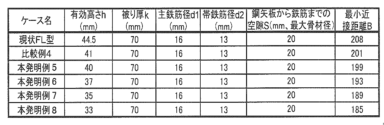
表2に示すように、有効高さhを40mm以下とした本発明例5~本発明例8において、近接距離Bを200mm以下にすることができた。
次に、コンクリート最大骨材径が20mmの充填コンクリートを用い、コンクリート最大骨材径に対し4/3倍以上の隙間が必要である場合を想定して、隙間Sを26mmとしたものについて説明する。
他の条件は表2の場合と同様に、被り厚kを70mm、主鉄筋径d1を16mm、帯鉄筋径d2を13mmとした。
上記条件で、継手部の有効高さhと近接距離Bとの対応関係についてまとめたものを表3に示す。
他の条件は表2の場合と同様に、被り厚kを70mm、主鉄筋径d1を16mm、帯鉄筋径d2を13mmとした。
上記条件で、継手部の有効高さhと近接距離Bとの対応関係についてまとめたものを表3に示す。
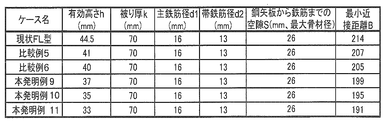
この場合、表3に示すように、有効高さhを37mm以下とした本発明例9~本発明例11において、近接距離Bを200mm以下にすることができた。
1 直線形鋼矢板
3 継手部
3a 主爪部
3b 副爪部
5 ウェブ部
7 補強構造
50 直線形鋼矢板(従来例)
51 継手部
51a 主爪部
51b 副爪部
52 ウェブ部
53 既存構造物(橋脚)
55 フーチング
57 地面
59 充填コンクリート
61 補強鉄筋
61a 主鉄筋
61b 帯鉄筋
3 継手部
3a 主爪部
3b 副爪部
5 ウェブ部
7 補強構造
50 直線形鋼矢板(従来例)
51 継手部
51a 主爪部
51b 副爪部
52 ウェブ部
53 既存構造物(橋脚)
55 フーチング
57 地面
59 充填コンクリート
61 補強鉄筋
61a 主鉄筋
61b 帯鉄筋
Claims (4)
- 両端に主爪と副爪からなる継手部を有する直線形鋼矢板であって、
継手の主爪高gが6.0mm以上、主爪厚f3とウェブ部板厚f1の比f3/f1が0.82以上、副爪厚f2とウェブ部板厚f1の比f2/f1が1.16以上、継手開口高さcと主爪厚f3との比c/f3が1.25以上であり、ウェブ部の中心位置から副爪部の最外縁までの距離h(有効高さ)が40mm以下である直線形鋼矢板。 - 両端に主爪と副爪からなる継手部を有する直線形鋼矢板であって、
継手の主爪高gが6.0mm以上、主爪厚f3とウェブ部板厚f1の比f3/f1が0.82以上、副爪厚f2とウェブ部板厚f1の比f2/f1が1.16以上、継手開口高さcと主爪厚f3との比c/f3が1.25以上であり、ウェブ部の中心位置から副爪部の最外縁までの距離h(有効高さ)が37mm以下である直線形鋼矢板。 - 直線形鋼矢板により構造物の周辺を囲んで補強する構造物の補強構造であって、
請求項1又は2の直線形鋼矢板により、前記構造物と前記直線形鋼矢板壁との近接距離が200mm以下となるように前記構造物の周辺を囲み、前記直線形鋼矢板と前記構造物との隙間に補強鉄筋を配置するとともに固化材を充填してなる構造物の補強構造。 - 直線形鋼矢板により構造物の周辺を囲んで補強する構造物の補強方法であって、
請求項1又は2の直線形鋼矢板により、前記構造物と前記直線形鋼矢板壁との近接距離が200mm以下となるように前記構造物の周辺を囲む工程と、前記直線形鋼矢板と前記構造物との間の土砂を除去する工程と、前記直線形鋼矢板と前記構造物との隙間に補強鉄筋を配置するとともに固化材を充填する工程とを備えた構造物の補強方法。
Priority Applications (2)
| Application Number | Priority Date | Filing Date | Title |
|---|---|---|---|
| SG11201605861VA SG11201605861VA (en) | 2014-03-03 | 2015-03-02 | Straight web steel sheet pile, and reinforcing structure and reinforcing method for structures using said straight web steel sheet pile |
| CN201580011676.3A CN106062281A (zh) | 2014-03-03 | 2015-03-02 | 直线形钢板桩、使用了该直线形钢板桩的结构物的加强结构及加强方法 |
Applications Claiming Priority (2)
| Application Number | Priority Date | Filing Date | Title |
|---|---|---|---|
| JP2014040308A JP5871023B2 (ja) | 2014-03-03 | 2014-03-03 | 直線形鋼矢板、該直線形鋼矢板を用いた構造物の補強構造及び補強方法 |
| JP2014-040308 | 2014-03-03 |
Publications (1)
| Publication Number | Publication Date |
|---|---|
| WO2015133111A1 true WO2015133111A1 (ja) | 2015-09-11 |
Family
ID=54054929
Family Applications (1)
| Application Number | Title | Priority Date | Filing Date |
|---|---|---|---|
| PCT/JP2015/001071 Ceased WO2015133111A1 (ja) | 2014-03-03 | 2015-03-02 | 直線形鋼矢板、該直線形鋼矢板を用いた構造物の補強構造及び補強方法 |
Country Status (5)
| Country | Link |
|---|---|
| JP (1) | JP5871023B2 (ja) |
| CN (1) | CN106062281A (ja) |
| MY (1) | MY176962A (ja) |
| SG (1) | SG11201605861VA (ja) |
| WO (1) | WO2015133111A1 (ja) |
Families Citing this family (3)
| Publication number | Priority date | Publication date | Assignee | Title |
|---|---|---|---|---|
| JP6740891B2 (ja) * | 2016-12-22 | 2020-08-19 | Jfeスチール株式会社 | ハット形鋼矢板 |
| JP7135740B2 (ja) * | 2018-11-02 | 2022-09-13 | 日本製鉄株式会社 | 鋼矢板 |
| JP6741136B2 (ja) * | 2019-10-07 | 2020-08-19 | Jfeスチール株式会社 | ハット形鋼矢板の製造方法及び設計方法 |
Citations (3)
| Publication number | Priority date | Publication date | Assignee | Title |
|---|---|---|---|---|
| JPS5620227A (en) * | 1979-07-26 | 1981-02-25 | Kawasaki Steel Corp | Linear type steel sheet-pile |
| JPH09125317A (ja) * | 1995-10-27 | 1997-05-13 | Nippon Steel Corp | 鉄筋コンクリート柱脚の補強構造及び補強方法 |
| JP2001355231A (ja) * | 2000-06-14 | 2001-12-26 | Kawasaki Steel Corp | 連結部疲労特性に優れた熱間圧延製直線型形鋼 |
Family Cites Families (8)
| Publication number | Priority date | Publication date | Assignee | Title |
|---|---|---|---|---|
| JPH0396556A (ja) * | 1989-09-11 | 1991-04-22 | Taisei Corp | 鉄筋の接合構造 |
| JPH11350737A (ja) * | 1998-06-04 | 1999-12-21 | Kyoei Steel Ltd | 鉄筋の接続構造 |
| JP4217150B2 (ja) * | 2003-12-19 | 2009-01-28 | 東日本旅客鉄道株式会社 | 橋脚の補強方法 |
| DE102004024103B3 (de) * | 2004-05-14 | 2006-01-05 | Pilepro Llc | Strangförmiges Verbindungsprofil zum Anschließen von Spundbohlen an Trägerelemente |
| JP2007297826A (ja) * | 2006-04-28 | 2007-11-15 | East Japan Railway Co | 橋脚の鋼板を用いた補強方法 |
| WO2010082468A1 (ja) * | 2009-01-16 | 2010-07-22 | 新日本製鐵株式会社 | 組合せ鋼矢板、組合せ鋼矢板により構成される土留め壁、及び組合せ鋼矢板の選定方法 |
| JPWO2010089966A1 (ja) * | 2009-02-04 | 2012-08-09 | 新日本製鐵株式会社 | 組合せ鋼矢板、組合せ鋼矢板を利用した連続壁、及び組合せ鋼矢板の圧入方法 |
| WO2013171909A1 (ja) * | 2012-05-16 | 2013-11-21 | Jfeスチール株式会社 | 組合せ鋼製壁 |
-
2014
- 2014-03-03 JP JP2014040308A patent/JP5871023B2/ja active Active
-
2015
- 2015-03-02 CN CN201580011676.3A patent/CN106062281A/zh active Pending
- 2015-03-02 MY MYPI2016703180A patent/MY176962A/en unknown
- 2015-03-02 SG SG11201605861VA patent/SG11201605861VA/en unknown
- 2015-03-02 WO PCT/JP2015/001071 patent/WO2015133111A1/ja not_active Ceased
Patent Citations (3)
| Publication number | Priority date | Publication date | Assignee | Title |
|---|---|---|---|---|
| JPS5620227A (en) * | 1979-07-26 | 1981-02-25 | Kawasaki Steel Corp | Linear type steel sheet-pile |
| JPH09125317A (ja) * | 1995-10-27 | 1997-05-13 | Nippon Steel Corp | 鉄筋コンクリート柱脚の補強構造及び補強方法 |
| JP2001355231A (ja) * | 2000-06-14 | 2001-12-26 | Kawasaki Steel Corp | 連結部疲労特性に優れた熱間圧延製直線型形鋼 |
Also Published As
| Publication number | Publication date |
|---|---|
| JP2015165074A (ja) | 2015-09-17 |
| JP5871023B2 (ja) | 2016-03-01 |
| MY176962A (en) | 2020-08-28 |
| SG11201605861VA (en) | 2016-09-29 |
| CN106062281A (zh) | 2016-10-26 |
Similar Documents
| Publication | Publication Date | Title |
|---|---|---|
| KR101364922B1 (ko) | 약축보강형 비좌굴 가새 | |
| JP5894039B2 (ja) | 斜ケーブルの定着構造 | |
| WO2015133111A1 (ja) | 直線形鋼矢板、該直線形鋼矢板を用いた構造物の補強構造及び補強方法 | |
| CN105064375B (zh) | 一种基坑支护挡土、止水结构的施工方法 | |
| JP2017106307A (ja) | セグメント | |
| JP6451476B2 (ja) | 鋼床版 | |
| JP7205824B2 (ja) | 二重鋼管付きコンクリート杭、その設計方法、その使用方法及びそれを備える杭基礎 | |
| WO2016181669A1 (ja) | 支柱下端部とコンクリート杭との剛結構造体 | |
| US20050210821A1 (en) | Pole reinforcement truss | |
| WO2005103405A2 (en) | Pole reinforcement truss | |
| WO2010082468A1 (ja) | 組合せ鋼矢板、組合せ鋼矢板により構成される土留め壁、及び組合せ鋼矢板の選定方法 | |
| JP2010089919A (ja) | 伸縮ブーム | |
| KR101933194B1 (ko) | 강성 보강된 콘크리트 말뚝의 제작방법 | |
| JP7370577B2 (ja) | 鉄筋コンクリート有孔梁の補強金具及び補強構造 | |
| US20200200297A1 (en) | Concrete Reinforcement Elements and Structures | |
| JP3726665B2 (ja) | 柱状コンクリート部材用横拘束筋及びそれを使用したコンクリート部材 | |
| JP5524644B2 (ja) | クレーン用ジブ | |
| CN218291920U (zh) | 一种混凝土预制桩 | |
| JP4416589B2 (ja) | 地中埋設中空構造物の補強方法及び地中埋設構造体 | |
| CN209568573U (zh) | 一种剪力墙体的新型加固结构 | |
| JP2009185532A (ja) | 異形鉄線溶接金網による重ね継手・定着工法 | |
| JP5516287B2 (ja) | トンネル接続構造およびトンネル施工方法 | |
| CN206562564U (zh) | 一种专用抱箍加固的桥梁 | |
| JP6389771B2 (ja) | 防護柵 | |
| CN206070878U (zh) | 柱帽 |
Legal Events
| Date | Code | Title | Description |
|---|---|---|---|
| 121 | Ep: the epo has been informed by wipo that ep was designated in this application |
Ref document number: 15758729 Country of ref document: EP Kind code of ref document: A1 |
|
| NENP | Non-entry into the national phase |
Ref country code: DE |
|
| WWE | Wipo information: entry into national phase |
Ref document number: IDP00201606605 Country of ref document: ID |
|
| 122 | Ep: pct application non-entry in european phase |
Ref document number: 15758729 Country of ref document: EP Kind code of ref document: A1 |