WO2013171909A1 - 組合せ鋼製壁 - Google Patents
組合せ鋼製壁 Download PDFInfo
- Publication number
- WO2013171909A1 WO2013171909A1 PCT/JP2012/063103 JP2012063103W WO2013171909A1 WO 2013171909 A1 WO2013171909 A1 WO 2013171909A1 JP 2012063103 W JP2012063103 W JP 2012063103W WO 2013171909 A1 WO2013171909 A1 WO 2013171909A1
- Authority
- WO
- WIPO (PCT)
- Prior art keywords
- steel sheet
- sheet pile
- shaped steel
- joint
- claw
- Prior art date
Links
Images


Classifications
-
- E—FIXED CONSTRUCTIONS
- E02—HYDRAULIC ENGINEERING; FOUNDATIONS; SOIL SHIFTING
- E02D—FOUNDATIONS; EXCAVATIONS; EMBANKMENTS; UNDERGROUND OR UNDERWATER STRUCTURES
- E02D5/00—Bulkheads, piles, or other structural elements specially adapted to foundation engineering
- E02D5/02—Sheet piles or sheet pile bulkheads
- E02D5/03—Prefabricated parts, e.g. composite sheet piles
- E02D5/04—Prefabricated parts, e.g. composite sheet piles made of steel
- E02D5/06—Fitted piles or other elements specially adapted for closing gaps between two sheet piles or between two walls of sheet piles
-
- E—FIXED CONSTRUCTIONS
- E02—HYDRAULIC ENGINEERING; FOUNDATIONS; SOIL SHIFTING
- E02D—FOUNDATIONS; EXCAVATIONS; EMBANKMENTS; UNDERGROUND OR UNDERWATER STRUCTURES
- E02D5/00—Bulkheads, piles, or other structural elements specially adapted to foundation engineering
- E02D5/02—Sheet piles or sheet pile bulkheads
- E02D5/03—Prefabricated parts, e.g. composite sheet piles
- E02D5/04—Prefabricated parts, e.g. composite sheet piles made of steel
- E02D5/08—Locking forms; Edge joints; Pile crossings; Branch pieces
Definitions
- the present invention relates to a combined steel wall used for harbor / river bank protection, mountain retaining, and deadline construction in the field of civil engineering and construction.
- a Z-shaped steel sheet pile means the steel sheet pile in which the flange was continuously formed in the both ends of the web arrange
- Patent Document 1 As a steel wall used for harbor and river revetment, mountain retaining, and deadline construction in the civil engineering and construction field, there is a combined steel wall combining a U-shaped steel sheet pile and an H-shaped steel (see Patent Document 1).
- the combined steel sheet pile described in Patent Document 1 is “U formed in a substantially U-shaped cross section from a web portion, a flange portion provided at both ends of the web portion, and an arm portion provided at one end of the flange portion. It is formed from a section steel sheet pile and an H-section steel that is installed with one flange fixed to the web portion on one side of the U-shaped steel sheet pile "(see claim 1 of Patent Document 1).
- Patent Document 1 The combined steel wall of Patent Document 1 is such that a web portion of a U-shaped steel sheet pile and a flange of an H-shaped steel are fixed in advance by welding or the like, and are sequentially placed on the ground. Therefore, there is a trouble that the U-shaped steel sheet pile and the H-shaped steel must be fixed in advance. Moreover, it has a complicated shape in which a U-shaped steel sheet pile and an H-shaped steel are fixed in advance, and since there is a large cross section, there is also a problem that ground resistance is large and placement is difficult. Moreover, since it is a shape which fixes the flange of a H-section steel to the web part of a U-shaped steel sheet pile, there also exists a problem that the steel weight per unit length is large and material cost becomes high.
- H-shaped steel is connected in parallel between the joint portion and the joint portion of the U-shaped steel sheet pile, the hat-shaped steel sheet pile, or the Z-shaped steel sheet pile
- It is called a Lalsen type and is not a shape that can be directly connected to other steel members such as H-shaped steel. Therefore, to construct a combined steel wall by connecting a conventional Z-shaped steel sheet pile or the like and an H-shaped steel in parallel, in order to connect the Z-shaped steel sheet pile or the like and the H-shaped steel, the H-shaped Z-shaped steel sheet pile or the like
- a separate connector is required to connect the two to steel.
- An object of the present invention is to provide a combined steel wall formed by connecting a Z-shaped steel sheet pile and an H-shaped steel without using a separate member called a connector.
- the combined steel wall according to the present invention has a flange portion at both ends of a web portion, and a Z-shaped steel sheet pile having a joint portion at each end of the flange portion and an H-shaped steel.
- a combined steel wall composed of: A flange portion of H-shaped steel is disposed along the axial direction of the flange portion of the Z-shaped steel sheet pile, a Z-shaped steel sheet pile is disposed along the axial direction of the flange portion of the H-shaped steel, and the Z shape It has a combination part arranged in the order of Z-shaped steel sheet pile, H-shaped steel, Z-shaped steel sheet pile in which the joint part of the steel sheet pile and the end of the flange part of the H-shaped steel are directly connected It is.
- the joint portion of the Z-shaped steel sheet pile includes a first joint portion formed at the tip of one flange portion constituting the Z-shaped steel sheet pile, and the other joint portion.
- the first joint portion has a bulge at the tip and a main claw disposed on the inner side of the steel sheet pile, and is formed to face the main claw.
- a double-claw joint having a sub-claw arranged on the outer side of the steel sheet pile
- the second joint portion has a main claw having a bulging portion at the tip and disposed on the outer side of the steel sheet pile, and a secondary claw disposed on the inner side of the steel sheet pile formed to face the main claw.
- the flange portion of the H-shaped steel is characterized in that a protrusion projecting in the thickness direction of the flange portion is provided at an end portion thereof.
- the first joint portion has a bulge at the tip and a main claw disposed inside the steel sheet pile, and is formed so as to face the main claw.
- a double-claw joint having a sub-claw arranged on the outer side of the steel sheet pile
- the second joint portion has a main claw having a bulging portion at the tip and disposed on the outer side of the steel sheet pile, and a secondary claw disposed on the inner side of the steel sheet pile formed to face the main claw.
- the flange portion of the H-shaped steel is provided with a groove portion at an end portion thereof.
- the first joint portion is provided at the tip of the flange portion via a first bent portion that bends toward the inside of the steel sheet pile.
- the second joint portion is provided at the front end of the flange portion via a second bent portion that is bent toward the inside of the steel sheet pile, and by providing the second bent portion, the outer surface of the main claw is provided on the sub-joint.
- the steel sheet pile is arranged by a distance equal to or greater than the thickness of the nail.
- the flange portion of the H-shaped steel is arranged along the axial direction of the flange portion of the Z-shaped steel sheet pile, and Z is aligned along the axial direction of the flange portion of the H-shaped steel.
- a shaped steel sheet pile is arranged, and has a combination part of a Z-shaped steel sheet pile, H-shaped steel, and Z-shaped steel sheet pile in which a joint portion of the Z-shaped steel sheet pile and an end portion of the flange portion of the H-shaped steel are directly connected. . Therefore, it is not necessary to fix the Z-shaped steel sheet pile and the H-shaped steel in advance, and the workability is excellent because each member can be placed on the ground.
- edge part of the flange part of H-section steel is directly connected with the joint part of Z-shaped steel sheet pile. Therefore, it is not necessary to use a separate connector or the like to connect the Z-shaped steel sheet pile and the H-shaped steel, which is excellent in workability and reduces the material cost.
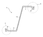
- FIG. 1 is an explanatory view of a combined steel wall according to an embodiment of the present invention.
- FIG. 2 is an enlarged view of a portion A surrounded by a circle in FIG.
- FIG. 3 is an explanatory view of a Z-shaped steel sheet pile constituting the combined steel wall according to one embodiment of the present invention.
- 4 is an enlarged view of a portion C surrounded by a circle in FIG.
- FIG. 5 is an enlarged view of a portion D surrounded by a circle in FIG.
- FIG. 6 is an explanatory diagram of the H-section steel constituting the combined steel wall according to one embodiment of the present invention.
- FIG. 7 is an explanatory view of another aspect of the H-shaped steel constituting the combined steel wall according to one embodiment of the present invention.
- the combined steel wall 1 has a flange portion at both ends of a web portion, and a Z-shaped steel sheet pile 2 having a joint portion at each end of the flange portion and an H-shaped steel 4 are connected.
- the flange portion of the H-shaped steel 4 is arranged along the axial direction of the flange portion of the Z-shaped steel sheet pile 2, and the axial direction of the flange portion of the H-shaped steel 4.
- Z-shaped steel sheet pile 2 is arranged along the Z-shaped steel sheet pile 2 and the joint of the Z-shaped steel sheet pile 2 and the end of the flange portion of the H-shaped steel 4 are directly connected.
- the Z-shaped steel sheet piles 2 are connected to each other at the end of the combined position of the Z-shaped steel sheet pile 2, the H-shaped steel 4, and the Z-shaped steel sheet pile 2. It will be.
- the Z-shaped steel sheet pile 2 and the H-shaped steel 4 constituting the combined steel wall 1 will be described in detail.
- the Z-shaped steel sheet pile 2 includes a first joint portion 5 formed at the tip of the first flange portion 3 constituting the Z-shaped steel sheet pile 2, and a second flange portion.
- Z having a second joint portion 9 formed at the tip of 7, Z-shaped steel sheet piles 2 can be arranged adjacent to each other, and the first joint portion 5 and the second joint portion 9 can be engaged and connected. It is a shaped steel sheet pile.
- the 1st joint part 5 has the bulging part 11 in the front-end
- the 2nd coupling part 9 has the bulging part 11 in the front-end
- the details of the Z-shaped steel sheet pile 2 will be described in more detail by dividing them into an overall shape and a joint part.
- the Z-shaped steel sheet pile 2 has a first flange portion 3 on one end side of a web portion 16 disposed obliquely, and a first joint portion 5 is formed at the tip of the first flange portion 3. It has the 2nd flange part 7 in the end side, the 2nd coupling part 9 is formed in the front-end
- the first joint part 5 and the second joint part 9 are divided into a joint body part 17 formed so as to be continuous with the front end of the flange part, and the joint body part 17 into two branches.
- the main claw 13 and the sub claw 15 are formed so as to face each other.
- the base is thin and the bulging part 11 is formed in the front-end
- the bulging portion 11 of the main claw 13 in the present embodiment has a substantially rectangular shape, and the shape of the entire main claw 13 is T-shaped.
- the bulging portion 11 is not limited to a rectangular shape, and may be a circle or an ellipse.
- the outer bent angle of the connecting portion 19 between the T-shaped horizontal piece and the vertical piece in the main claw 13 is sharper than the inner bent angle. Since the inner bending angle is smooth, the joint interior 21 surrounded by the main claws 13 and the sub claws 15 in the joint portion has a smooth arc shape. Since the joint interior 21 has a smooth arc shape, the degree of freedom of rotation of the entire Z-shaped steel sheet pile 2 is increased when the joint portions are connected.
- the sub claw 15 has a thick root and a thickness that decreases toward the tip, and has a smooth curved shape as a whole.
- the main claw 13 of the joint portion connected to the inside of the joint 21 surrounded by the main claw 13 and the sub claw 15 is inserted. Since the bulging portion 11 is formed on the main claw 13, the main claw 13 does not come out from the gap between the main claw 13 and the sub claw 15.
- the first joint portion 5 and the second joint portion 9 are common in that they have the main claws 13 and the sub claws 15 described above, but there are also differences.
- positioned at the right side in FIG. 3 are demonstrated separately.
- claw 15 is a steel sheet pile in the connected joint part. It is arranged outside.
- the outer side of the steel sheet pile refers to the side opposite to the side where the web portion 16 is present with respect to the axis of the first flange portion 3, and the opposite side to the inner side of the steel sheet pile, ie, the central axis of the first flange portion 3. The side where the web part 16 is located.
- the first joint part 5 is arranged on the steel sheet pile inner side so that the sub claws 15 are arranged on the steel sheet pile outer side and the main claws 13 are opposed to the sub claws 15.
- the first joint portion 5 is connected to the first flange portion 3 through a first bent portion 23 that bends from the first flange portion 3 to the inside of the steel sheet pile. Since the first joint portion 5 is provided via the first bent portion 23, the outermost part of the steel sheet pile on the outer surface of the sub claw 15 disposed on the outer side of the steel sheet pile is the first flange portion 3. It is designed to be flush with the outer surface (see FIGS. 2 and 4).
- claw 13 is arrange
- the 2nd joint part 9 is arrange
- the 2nd joint part 9 is connected with the 2nd flange part 7 via the 2nd bending part 25 bent from the 2nd flange part 7 to a steel sheet pile inner side.
- the second bent portion 25 has a longer extension distance to the inner side of the steel sheet pile than the first bent portion 23 formed on the first joint portion 5 side. Since the second joint portion 9 is provided via the second bent portion 25, the outermost part of the steel sheet pile on the outer surface of the main claw 13 disposed on the outer side of the steel sheet pile is the second flange portion 7. It arrange
- the distance S is set to a distance that is equal to or greater than the thickness of the auxiliary nail 15.
- the H-shaped steel 4 has a web portion 35 and a flange portion 37, and faces outward at the tip of the flange portion 37 (opposite to the web portion 35 with respect to the axis of the flange portion 37).
- a protruding projection 39 is provided. As shown in FIG. 1, the protrusion 39 is formed when the tip of the flange portion 37 of the H-shaped steel 4 is inserted into the first joint portion 5 or the second joint portion 9 of the Z-shaped steel sheet pile 2. Engages with the second joint portion 9.
- the projection 39 projects outward (on the opposite side to the web portion 35 with respect to the axis of the flange portion 37) as in the present embodiment, and also on the outside and inside (with respect to the axis of the flange portion 37). And the same projecting side as the web portion 35) or projecting only inward.
- the construction method of the combined steel wall 1 will be described.
- the Z-shaped steel sheet pile 2 on the left side in the figure is placed, and then the tip of the flange portion 37 of the H-shaped steel 4 is placed inside the joint of the first joint portion 5 of the Z-shaped steel sheet pile 2 ( The H-section steel 4 is driven in such a manner that the tip on the left side in the figure is inserted.
- the Z-shaped steel sheet pile 2 is made so that the other tip (the tip on the right side in the figure) of the flange portion 37 of the H-shaped steel 4 is inserted into the joint of the first joint portion 5 of the Z-shaped steel sheet pile 2. To cast.
- the Z-shaped steel sheet pile 2 is driven so that the second joint portion 9 of the cast Z-shaped steel sheet pile 2 and the first joint portion 5 of another Z-shaped steel sheet pile 2 are engaged.
- the tip of the flange portion 37 of the H-shaped steel 4 (the tip on the left side in the figure) is inserted into the joint of the second joint portion 9 of the cast Z-shaped steel sheet pile 2 so that the H-shaped steel 4 To cast.
- the Z-shaped steel sheet pile 2 is made so that the other tip (the right tip in the drawing) of the flange portion 37 of the H-shaped steel 4 is inserted into the joint of the second joint portion 9 of the Z-shaped steel sheet pile 2.
- the combined steel wall 1 is constructed.
- the double-claw joint portion of the present embodiment has a high degree of freedom in rotation.
- the joint portion is not deformed at the time of placing.
- the double-claw joint has a high resistance to the tensile force, so that deformation is small. Therefore, the highly accurate combination steel wall 1 can be formed.
- the joint portion of the present embodiment has a high degree of freedom of rotation, even when an earthquake force or the like is applied, excessive force does not act on the joint portion, and the joint portion is deformed or the like. There is nothing. Further, since the double-claw joint portion of the present embodiment is excellent in tensile strength, the joint portion is not deformed or the like when the Z-shaped steel sheet pile 2 receives a tensile force. Therefore, it is excellent in the water stoppage of the joint part.
- the combined steel wall 1 of the present embodiment can be constructed by directly connecting the Z-shaped steel sheet pile 2 and the H-shaped steel 4 without using a separate member called a connector.
- a plurality of Z-shaped steel sheet piles 2 are arranged next to the combination parts arranged in the order of Z-shaped steel sheet pile 2, H-shaped steel 4, and Z-shaped steel sheet pile 2, and then again the Z-shaped steel sheet pile. It arrange
- the groove part 40 may be provided on the outer side (the side opposite to the web part 35 with respect to the axis of the flange part 37), or the outer side and the inner side (with respect to the axis of the flange part 37). It may be provided both on the same side as the web portion 35, or may be provided only inside.
Landscapes
- Engineering & Computer Science (AREA)
- Structural Engineering (AREA)
- Chemical & Material Sciences (AREA)
- Composite Materials (AREA)
- Life Sciences & Earth Sciences (AREA)
- General Life Sciences & Earth Sciences (AREA)
- Mining & Mineral Resources (AREA)
- Paleontology (AREA)
- Civil Engineering (AREA)
- General Engineering & Computer Science (AREA)
- Bulkheads Adapted To Foundation Construction (AREA)
Abstract
Description
特許文献1に記載の組合せ鋼矢板は、「ウェブ部とこのウェブ部の両端に設けられたフランジ部とこのフランジ部の一端に設けられた腕部とから断面ほぼU字状に形成されたU形鋼矢板と、このU形鋼矢板の一側面に一方のフランジを前記ウェブ部に固定して設置されたH形鋼とから形成され」ている(特許文献1の請求項1参照)。
そのため、U形鋼矢板とH形鋼を予め固定しなければならないという手間がある。また、U形鋼矢板とH形鋼を予め固定した複雑な形状となっており、断面が大きいために地盤抵抗も大きく、打設が困難であるという問題もある。
また、U形鋼矢板のウェブ部にH形鋼のフランジを固定する形状であるため、単位長さあたりの鋼重が大きく、材料費が高くなるという問題もある。
そのため、従来のZ形鋼矢板等とH形鋼を並列接続させて組合せ鋼製壁を構築するには、Z形鋼矢板等とH形鋼を接続するためにZ形鋼矢板等とH形鋼との間に両者を連結するためのコネクターが別途必要になる。
さらに、コネクターの形状にもよるが、ラルゼン型継手部とH形鋼とを連結するとすれば、コネクター部分がZ形鋼矢板のフランジ部の外側に出っ張ることになり、当該部位の平面が保たれなくなる。そのため、腹起し部材を設置する際に余分な裏込めコンクリートが必要となるなど、施工手間が増えることになる。
前記Z形鋼矢板のフランジ部の軸線方向に沿うようにH形鋼のフランジ部が配置され、該H形鋼のフランジ部の軸線方向に沿うようにZ形鋼矢板が配置され、前記Z形鋼矢板の継手部と前記H形鋼のフランジ部の端部が直接連結されてなるZ形鋼矢板・H形鋼・Z形鋼矢板の順に配置された組合せ部位を有することを特徴とするものである。
前記第2継手部は、先端に膨出部を有し鋼矢板外側に配置される主爪と、該主爪に対向するように形成された鋼矢板内側に配置される副爪とを有する二重爪型の継手部であり、
前記H形鋼のフランジ部は、その端部にフランジ部の厚み方向に突出する突起を備えてなることを特徴とするものである。
前記第2継手部は、先端に膨出部を有し鋼矢板外側に配置される主爪と、該主爪に対向するように形成された鋼矢板内側に配置される副爪とを有する二重爪型の継手部であり、
前記H形鋼のフランジ部は、その端部に溝部を備えてなることを特徴とするものである。
前記第2継手部は、鋼矢板内側に向けて曲がる第2曲り部を介して前記フランジ部の先端に設けられており、前記第2曲り部を設けることにより、前記主爪の外面が前記副爪の厚み分以上の距離だけ鋼矢板内側に配置されていることを特徴とするものである。
以下、組合せ鋼製壁1を構成するZ形鋼矢板2とH形鋼4を詳細に説明する。
本実施の形態に係るZ形鋼矢板2は、図3に示すように、Z形鋼矢板2を構成する第1フランジ部3の先端に形成された第1継手部5と、第2フランジ部7の先端に形成された第2継手部9とを有し、Z形鋼矢板2を隣接配置して、第1継手部5と第2継手部9を係合させて連結することができるZ形鋼矢板である。
第1継手部5は、先端に膨出部11を有し鋼矢板内側に配置される主爪13と、主爪13に対向するように形成された鋼矢板外側に配置される副爪15とを有する二重爪型の継手部である(図4参照)。
また、第2継手部9は、先端に膨出部11を有し鋼矢板外側に配置される主爪13と、主爪13に対向するように形成された鋼矢板内側に配置される副爪15とを有する二重爪型の継手部である(図5参照)。
以下、Z形鋼矢板2の詳細を、全体形状、継手部に分けてさらに詳細に説明する。
Z形鋼矢板2は、斜めに配置されたウェブ部16の一端側に第1フランジ部3を有し、第1フランジ部3の先端に第1継手部5が形成され、ウェブ部16の他端側に第2フランジ部7を有し、第2フランジ部7の先端に第2継手部9が形成され、全体として略Z形になっている。
第1継手部5と第2継手部9の基本形状は同じであるので、それを図4、図5に基づいて説明する。
第1継手部5と第2継手部9は、図4、図5に示すように、フランジ部の先端に連続するように形成された継手本体部17と、該継手本体部17から二股に分かれて互いに対向するように形成された主爪13と、副爪15を有している。
主爪13は、根元が細く先端に膨出部11が形成されている。本実施の形態における主爪13の膨出部11は略矩形をしており、主爪13全体の形状がT字状をしている。膨出部11は矩形状に限らず、円形、楕円形のようなものであってもよい。
主爪13と副爪15で囲まれる継手内部21に、これに連結される継手部の主爪13が挿入される。主爪13に膨出部11が形成されていることから、主爪13と副爪15との隙間から主爪13が抜け出さないようになっている。
第1継手部5は、第1継手部5と第2継手部9を連結して組合せ鋼製壁1(図1参照)を形成するときに、連結された継手部において副爪15が鋼矢板外側に配置されるものである。
なお、鋼矢板外側とは、第1フランジ部3の軸線に対してウェブ部16がある側と反対側をいい、鋼矢板内側とはその反対側、すなわち第1フランジ部3の中心軸に対してウェブ部16がある側をいう。
第2継手部9は、第1継手部5と第2継手部9を連結して組合せ鋼製壁1を形成するときに、連結された継手部において主爪13が鋼矢板外側に配置されるものである。
第2継手部9は、主爪13が鋼矢板外側に配置され、副爪15が主爪13に対向するように鋼矢板内側に配置されている。
第2継手部9は、第2曲り部25を介して設けられていることにより、鋼矢板外側に配置されている主爪13の外面における最も鋼矢板外側の部位が、第2フランジ部7の外面よりも、距離Sだけ内側に配置されている(図5参照)。なお、距離Sは、副爪15の厚み以上の距離に設定されている。
H形鋼4は、図6に示すように、ウェブ部35とフランジ部37を有し、フランジ部37の先端に外側(フランジ部37の軸線に対してウェブ部35と反対側)に向けて突出する突起39を備えている。
突起39は、図1に示すように、Z形鋼矢板2の第1継手部5又は第2継手部9にH形鋼4のフランジ部37の先端を挿入した際に第1継手部5又は第2継手部9に係合する。このため、H形鋼4に対して、フランジ部37の軸線方向に引張り力が作用してもH形鋼4のフランジ部37が第1継手部5又は第2継手部9から抜け出さない。
なお、突起39は、本実施の形態のように、外側(フランジ部37の軸線に対してウェブ部35と反対側)に向けて突出するものの他、外側と内側(フランジ部37の軸線に対してウェブ部35と同じ側)の両方に突出するもの、あるいは内側にのみ突出するものであってもよい。
図1に示すように、例えば図中左側のZ形鋼矢板2を打設し、次にZ形鋼矢板2の第1継手部5の継手内部にH形鋼4のフランジ部37の先端(図中左側の先端)を挿入するようにして、H形鋼4を打設する。
次に、H形鋼4のフランジ部37の他方の先端(図中右側の先端)がZ形鋼矢板2の第1継手部5の継手内部に挿入されるようにしてZ形鋼矢板2を打設する。次に、打設されたZ形鋼矢板2の第2継手部9と別のZ形鋼矢板2の第1継手部5が係合するようにしてZ形鋼矢板2を打設する。次に、打設されたZ形鋼矢板2の第2継手部9の継手内部にH形鋼4のフランジ部37の先端(図中左側の先端)を挿入するようにして、H形鋼4を打設する。次に、H形鋼4のフランジ部37の他方の先端(図中右側の先端)がZ形鋼矢板2の第2継手部9の継手内部に挿入されるようにしてZ形鋼矢板2を打設する。
同様のことを繰り返すことにより、組合せ鋼製壁1が構築される。
2枚のZ形鋼矢板2の第1フランジ部3の外面が面一になることで、当該部位に直接腹越し材を設置することが可能になる。仮に、コネクターなどを使用した場合において、コネクターが鋼矢板外側に出っ張ると、当該部位に例えばコンクリート等を介在させて腹越し材を設置しなければならないが、本実施の形態のものではそのような手間がなく作業性に優れている。
また、本実施の形態の二重爪型の継手部は、引張り強度に優れているので、その意味でもZ形鋼矢板2が引張り力を受けたときに継手部が変形等しない。それ故に、継手部の止水性に優れている。
(a)Z形鋼矢板2・H形鋼4・Z形鋼矢板2・H形鋼4・Z形鋼矢板2・H形鋼4・・というようにZ形鋼矢板2とH形鋼4を交互に配置する。
(b)Z形鋼矢板2・H形鋼4・Z形鋼矢板2の順に配置された組合せ部位の隣に複数枚のZ形鋼矢板2を配置して、その次に再びZ形鋼矢板2・H形鋼4・Z形鋼矢板2の順に配置された組合せ部位があるように配置する。
なお、溝部40は、図7に示すように、外側(フランジ部37の軸線に対してウェブ部35と反対側)に設けてもよいし、あるいは外側と内側(フランジ部37の軸線に対してウェブ部35と同じ側)の両方に設けてもよく、またあるいは内側にのみ設けるようにしてもよい。
2 Z形鋼矢板
3 第1フランジ部
4 H形鋼
5 第1継手部
7 第2フランジ部
9 第2継手部
11 膨出部
13 主爪
15 副爪
16 ウェブ部
17 継手本体部
19 連結部
21 継手内部
23 第1曲り部
25 第2曲り部
27 鋼矢板壁
35 ウェブ部
37 フランジ部
39 突起
40 溝部
Claims (5)
- ウェブ部の両端にフランジ部を有し、該フランジ部の各端部に継手部を有するZ形鋼矢板と、H形鋼とを連結して構成される組合せ鋼製壁であって、
前記Z形鋼矢板のフランジ部の軸線方向に沿うようにH形鋼のフランジ部が配置され、該H形鋼のフランジ部の軸線方向に沿うようにZ形鋼矢板が配置され、前記Z形鋼矢板の継手部と前記H形鋼のフランジ部の端部が直接連結されてなるZ形鋼矢板・H形鋼・Z形鋼矢板の順に配置された組合せ部位を有することを特徴とする組合せ鋼製壁。 - 前記Z形鋼矢板の継手部は、Z形鋼矢板を構成する一方のフランジ部の先端に形成された第1継手部と、他方のフランジ部の先端に形成された第2継手部とを有し、Z形鋼矢板が隣接配置されたときに、前記第1継手部と前記第2継手部が係合可能になっており、前記Z形鋼矢板・H形鋼・Z形鋼矢板の組合せ部位の端に位置するZ形鋼矢板同士が連結されてなることを特徴とする請求項1記載の組合せ鋼製壁。
- 前記第1継手部は、先端に膨出部を有し鋼矢板内側に配置される主爪と、該主爪に対向するように形成された鋼矢板外側に配置される副爪とを有する二重爪型の継手部であり、
前記第2継手部は、先端に膨出部を有し鋼矢板外側に配置される主爪と、該主爪に対向するように形成された鋼矢板内側に配置される副爪とを有する二重爪型の継手部であり、
前記H形鋼のフランジ部は、その端部にフランジ部の厚み方向に突出する突起を備えてなることを特徴とする請求項2記載の組合せ鋼製壁。 - 前記第1継手部は、先端に膨出部を有し鋼矢板内側に配置される主爪と、該主爪に対向するように形成された鋼矢板外側に配置される副爪とを有する二重爪型の継手部であり、
前記第2継手部は、先端に膨出部を有し鋼矢板外側に配置される主爪と、該主爪に対向するように形成された鋼矢板内側に配置される副爪とを有する二重爪型の継手部であり、
前記H形鋼のフランジ部は、その端部に溝部を備えてなることを特徴とする請求項2記載の組合せ鋼製壁。 - 前記第1継手部は、鋼矢板内側に向けて曲がる第1曲り部を介して前記フランジ部の先端に設けられており、前記第1曲り部を設けることにより、前記副爪の外面がフランジ部の外面よりも鋼矢板外側に突出しないようになっており、
前記第2継手部は、鋼矢板内側に向けて曲がる第2曲り部を介して前記フランジ部の先端に設けられており、前記第2曲り部を設けることにより、前記主爪の外面が前記副爪の厚み分以上の距離だけ鋼矢板内側に配置されていることを特徴とする請求項3又は4記載の組合せ鋼製壁。
Priority Applications (4)
| Application Number | Priority Date | Filing Date | Title |
|---|---|---|---|
| KR1020147029682A KR20140139049A (ko) | 2012-05-16 | 2012-05-16 | 조합 강제 벽 |
| PCT/JP2012/063103 WO2013171909A1 (ja) | 2012-05-16 | 2012-05-16 | 組合せ鋼製壁 |
| CN201280073163.1A CN104285010B (zh) | 2012-05-16 | 2012-05-16 | 组合钢板墙 |
| SG11201406539SA SG11201406539SA (en) | 2012-05-16 | 2012-05-16 | Combined steel wall |
Applications Claiming Priority (1)
| Application Number | Priority Date | Filing Date | Title |
|---|---|---|---|
| PCT/JP2012/063103 WO2013171909A1 (ja) | 2012-05-16 | 2012-05-16 | 組合せ鋼製壁 |
Publications (1)
| Publication Number | Publication Date |
|---|---|
| WO2013171909A1 true WO2013171909A1 (ja) | 2013-11-21 |
Family
ID=49583349
Family Applications (1)
| Application Number | Title | Priority Date | Filing Date |
|---|---|---|---|
| PCT/JP2012/063103 WO2013171909A1 (ja) | 2012-05-16 | 2012-05-16 | 組合せ鋼製壁 |
Country Status (4)
| Country | Link |
|---|---|
| KR (1) | KR20140139049A (ja) |
| CN (1) | CN104285010B (ja) |
| SG (1) | SG11201406539SA (ja) |
| WO (1) | WO2013171909A1 (ja) |
Cited By (3)
| Publication number | Priority date | Publication date | Assignee | Title |
|---|---|---|---|---|
| CN106062281A (zh) * | 2014-03-03 | 2016-10-26 | 杰富意钢铁株式会社 | 直线形钢板桩、使用了该直线形钢板桩的结构物的加强结构及加强方法 |
| CN108729450A (zh) * | 2018-05-30 | 2018-11-02 | 中水电第十工程局(郑州)有限公司 | 一种管道工程钢板桩支护方法 |
| CN111074880A (zh) * | 2018-10-19 | 2020-04-28 | J.D.菲尔兹公司 | 组合墙打桩系统 |
Families Citing this family (1)
| Publication number | Priority date | Publication date | Assignee | Title |
|---|---|---|---|---|
| CN105064379B (zh) * | 2015-08-29 | 2017-02-22 | 青岛蓝天创先科技服务有限公司 | 一种h型钢基坑支护装置及方法 |
Citations (2)
| Publication number | Priority date | Publication date | Assignee | Title |
|---|---|---|---|---|
| JP2005307740A (ja) * | 2004-04-23 | 2005-11-04 | Pilepro Llc | 支持要素に矢板を接続する長尺の連結体 |
| US20110076103A1 (en) * | 2006-09-01 | 2011-03-31 | Rob Wendt | Barrier wall made of sheet-pile components |
Family Cites Families (7)
| Publication number | Priority date | Publication date | Assignee | Title |
|---|---|---|---|---|
| JP3488232B1 (ja) * | 2002-11-15 | 2004-01-19 | 新日本製鐵株式会社 | 圧延鋼矢板 |
| JP4384551B2 (ja) * | 2004-06-07 | 2009-12-16 | 新日本製鐵株式会社 | 鋼矢板 |
| PL1974101T3 (pl) * | 2006-01-17 | 2011-03-31 | Arcelormittal Commercial Rps S A R L | Grodzica w formie dwuteownika |
| DE102007020747A1 (de) * | 2007-05-03 | 2008-11-13 | Pilepro Llc | Anordnung aus mehreren Spundwandkomponenten sowie Anschweißprofil hierfür |
| SG172878A1 (en) * | 2009-01-16 | 2011-08-29 | Nippon Steel Corp | Combined steel sheet pile, earth-retaining wall formed by combined steel sheet pile, and method of selecting combined steel sheet pile |
| JP5282984B2 (ja) * | 2010-03-12 | 2013-09-04 | 新日鐵住金株式会社 | 鋼製連続壁の施工方法および鋼製連続壁 |
| CN201915389U (zh) * | 2010-12-17 | 2011-08-03 | 南京万汇新材料科技有限公司 | H形与z形组合钢板桩 |
-
2012
- 2012-05-16 SG SG11201406539SA patent/SG11201406539SA/en unknown
- 2012-05-16 KR KR1020147029682A patent/KR20140139049A/ko not_active Application Discontinuation
- 2012-05-16 WO PCT/JP2012/063103 patent/WO2013171909A1/ja active Application Filing
- 2012-05-16 CN CN201280073163.1A patent/CN104285010B/zh active Active
Patent Citations (2)
| Publication number | Priority date | Publication date | Assignee | Title |
|---|---|---|---|---|
| JP2005307740A (ja) * | 2004-04-23 | 2005-11-04 | Pilepro Llc | 支持要素に矢板を接続する長尺の連結体 |
| US20110076103A1 (en) * | 2006-09-01 | 2011-03-31 | Rob Wendt | Barrier wall made of sheet-pile components |
Cited By (3)
| Publication number | Priority date | Publication date | Assignee | Title |
|---|---|---|---|---|
| CN106062281A (zh) * | 2014-03-03 | 2016-10-26 | 杰富意钢铁株式会社 | 直线形钢板桩、使用了该直线形钢板桩的结构物的加强结构及加强方法 |
| CN108729450A (zh) * | 2018-05-30 | 2018-11-02 | 中水电第十工程局(郑州)有限公司 | 一种管道工程钢板桩支护方法 |
| CN111074880A (zh) * | 2018-10-19 | 2020-04-28 | J.D.菲尔兹公司 | 组合墙打桩系统 |
Also Published As
| Publication number | Publication date |
|---|---|
| CN104285010A (zh) | 2015-01-14 |
| SG11201406539SA (en) | 2014-11-27 |
| KR20140139049A (ko) | 2014-12-04 |
| CN104285010B (zh) | 2016-01-20 |
Similar Documents
| Publication | Publication Date | Title |
|---|---|---|
| US9506212B2 (en) | Universal connecting element for sheet pile wall components | |
| EP2672012B1 (en) | A mono-pile type foundation structure for connecting steel pipe pile and steel sleeve pipe | |
| EP2554751A1 (en) | Connected wall structure consisting of steel pipe sheet piles and steel sheet pile, and method of constructing same | |
| WO2013171909A1 (ja) | 組合せ鋼製壁 | |
| JP5257470B2 (ja) | 組合せ鋼製壁 | |
| JP2006241816A (ja) | 地中連続壁 | |
| JP4014216B2 (ja) | 構造材、接続構造体及び構造材の接続方法 | |
| JP5521277B2 (ja) | ハット形鋼矢板 | |
| JP2017066702A (ja) | 鋼矢板の縦継構造及び鋼矢板壁 | |
| JP6714307B2 (ja) | 既設鋼矢板壁の補強工法 | |
| JP5114731B2 (ja) | 地中連続壁体の設計方法 | |
| WO2013171910A1 (ja) | Z形鋼矢板、該z形鋼矢板で形成された鋼矢板壁 | |
| JP5737058B2 (ja) | H形鋼矢板 | |
| SG189307A1 (en) | Steel sheet pile and steel sheet pile wall formed of such steel sheet piles | |
| JP2012167430A (ja) | Z形鋼矢板、該z形鋼矢板で形成された鋼矢板壁 | |
| JP6515293B2 (ja) | 鋼矢板壁 | |
| JP5633502B2 (ja) | 壁体構造 | |
| JP5079731B2 (ja) | 表面板と主桁を連結する合成セグメント、合成セグメントの製造方法およびトンネル | |
| JP6489055B2 (ja) | 既設鋼矢板壁の補強構造および補強工法 | |
| TWI480448B (zh) | Combination of steel wall | |
| JP5637657B2 (ja) | 土留壁及びその補強方法 | |
| JP2013199746A (ja) | 土留壁 | |
| JP2007040086A (ja) | 鋼管の連結構造 | |
| TWI516659B (zh) | Z-shaped steel sheet pile, the Z-shaped steel sheet pile formed by the steel sheet pile wall | |
| JP2017198035A (ja) | 鋼矢板壁 |
Legal Events
| Date | Code | Title | Description |
|---|---|---|---|
| 121 | Ep: the epo has been informed by wipo that ep was designated in this application |
Ref document number: 12876918 Country of ref document: EP Kind code of ref document: A1 |
|
| ENP | Entry into the national phase |
Ref document number: 20147029682 Country of ref document: KR Kind code of ref document: A |
|
| NENP | Non-entry into the national phase |
Ref country code: DE |
|
| 122 | Ep: pct application non-entry in european phase |
Ref document number: 12876918 Country of ref document: EP Kind code of ref document: A1 |
|
| NENP | Non-entry into the national phase |
Ref country code: JP |