WO2013171910A1 - Z形鋼矢板、該z形鋼矢板で形成された鋼矢板壁 - Google Patents
Z形鋼矢板、該z形鋼矢板で形成された鋼矢板壁 Download PDFInfo
- Publication number
- WO2013171910A1 WO2013171910A1 PCT/JP2012/063107 JP2012063107W WO2013171910A1 WO 2013171910 A1 WO2013171910 A1 WO 2013171910A1 JP 2012063107 W JP2012063107 W JP 2012063107W WO 2013171910 A1 WO2013171910 A1 WO 2013171910A1
- Authority
- WO
- WIPO (PCT)
- Prior art keywords
- steel sheet
- sheet pile
- joint
- claw
- shaped steel
- Prior art date
Links
Images


Classifications
-
- E—FIXED CONSTRUCTIONS
- E02—HYDRAULIC ENGINEERING; FOUNDATIONS; SOIL SHIFTING
- E02D—FOUNDATIONS; EXCAVATIONS; EMBANKMENTS; UNDERGROUND OR UNDERWATER STRUCTURES
- E02D5/00—Bulkheads, piles, or other structural elements specially adapted to foundation engineering
- E02D5/02—Sheet piles or sheet pile bulkheads
- E02D5/03—Prefabricated parts, e.g. composite sheet piles
- E02D5/04—Prefabricated parts, e.g. composite sheet piles made of steel
- E02D5/08—Locking forms; Edge joints; Pile crossings; Branch pieces
Definitions
- the present invention relates to a Z-shaped steel sheet pile used for harbor / river revetment, mountain retaining, and deadline construction in the field of civil engineering and construction, and a steel sheet pile wall formed from the Z-shaped steel sheet pile.
- a Z-shaped steel sheet pile refers to a steel sheet pile in which flanges are continuously formed on both ends of a web arranged obliquely and the overall shape is substantially Z-shaped.
- U-shaped steel sheet piles, Z-shaped steel sheet piles, or hat-shaped steel sheet piles are used as steel sheet piles used for harbor / river revetment, mountain retaining, and deadline construction in the field of civil engineering and construction.
- the linear steel sheet pile is mainly used for the steel sheet pile cell construction method.
- These steel sheet piles are used as steel walls by connecting joints.
- a joint portion of a U-shaped steel sheet pile, a hat-shaped steel sheet pile, and a Z-shaped steel sheet pile is generally called a larsen type (see Patent Documents 1 and 2).
- mold is used for the linear steel sheet pile, and the Larzen type is used as a special example (refer patent document 3).
- the center of gravity of the U-shaped steel sheet pile does not coincide with the center of gravity of the steel sheet pile wall because the joint is located at the center of the steel sheet pile wall after construction. Accordingly, when the steel sheet pile wall is subjected to bending due to an applied load such as earth pressure, the joint portion is displaced, and the rigidity and section modulus of the steel sheet pile wall are lowered, so that it is necessary to reduce the joint efficiency.
- the hat-shaped steel sheet pile has excellent cross-sectional performance with respect to weight per unit wall area, it is currently commercialized as a type of cross-sectional second moment per 1 m of wall width due to manufacturing restrictions. There are only two types. In comparison, Z-shaped steel sheet piles have many types of cross-sectional secondary moments per 1 m of wall width, and the maximum cross-sectional secondary moment is about 10 times that of hat-shaped steel sheet piles. Moreover, since it becomes a hat shape if a Z-shaped steel sheet pile is connected, it is possible to construct a steel sheet pile wall excellent in economic efficiency and cross-sectional performance according to the required performance if a Z-shaped steel sheet pile is used. .
- the Z-shaped steel sheet pile can construct a steel sheet pile wall excellent in economic efficiency and cross-sectional performance.
- a Larsen type has been conventionally used in the same manner as the U-shaped steel sheet pile and the hat-shaped steel sheet pile.
- the Larzen type is used because it is easier to manufacture than the double nail type.
- whether or not the Ralsen type is optimal as a joint portion of the Z-shaped steel sheet pile has not been studied in detail. Therefore, when the joint of the Z-shaped steel sheet pile is examined as to whether the conventionally used Ralzen type is optimal, it has been found that there are the following problems.
- FIG. 6 schematically shows various forces acting on the joint portion 31 of the conventional Z-shaped steel sheet pile 29 having a Larzen type joint.
- the force acting on the joint portion 31 includes a tensile force and a compressive force acting in the axial direction of the flange portion 33, a rotational force centered on the joint portion, and a direction orthogonal to the flange portion.
- Larzen type joints are easily deformed when a tensile force or rotational force is applied.
- the above-described force acting on the joint portion 31 may cause a phenomenon in which the opening width of the joint portion 31 is closed or opened. If the opening width of the joint portion 31 is too wide, the steel sheet piles may be separated from each other. Conversely, if the opening width of the joint portion 31 is too closed, the subsequent steel sheet pile may not be driven.
- the joint portion of the Z-shaped steel sheet pile has a problem that a force is easily applied to the joint portion during and after the steel sheet pile is placed, and therefore, the joint portion is likely to be deformed.
- a method of increasing the thickness of the joint portion is conceivable.
- increasing the plate thickness leads to an increase in the weight of the steel material, resulting in poor economic efficiency.
- the present invention provides a Z-shaped steel sheet pile capable of constructing a highly accurate steel sheet pile wall without increasing the steel weight, without causing deformation or the like in the joint portion during or after the steel sheet pile is placed.
- the purpose is that.
- Another object of the present invention is to obtain a highly accurate steel sheet pile wall.
- the Z-shaped steel sheet pile according to the present invention includes a first joint portion formed at the tip of one flange portion constituting the Z-shaped steel sheet pile and a second joint portion formed at the tip of the other flange portion.
- a Z-shaped steel sheet pile that can form a steel sheet pile wall by engaging and connecting the first joint part and the second joint part,
- the first joint portion has a main claw having a bulging portion at the tip and disposed inside the steel sheet pile, and a secondary claw disposed outside the steel sheet pile formed to face the main claw.
- the second joint portion has a main claw having a bulging portion at the tip and disposed on the outer side of the steel sheet pile, and a secondary claw disposed on the inner side of the steel sheet pile formed to face the main claw. It is a double-claw joint.
- the first joint portion is provided at a front end of the flange portion via a first bent portion that is bent toward the inner side of the steel sheet pile.
- the second joint portion is provided at the front end of the flange portion via a second bent portion that is bent toward the inside of the steel sheet pile, and by providing the second bent portion, the outer surface of the main claw is provided on the sub-joint.
- the steel sheet pile is arranged by a distance equal to or greater than the thickness of the nail.
- the steel sheet pile wall according to the present invention is formed by connecting the Z-shaped steel sheet piles according to the above (1) or (2).
- the Z-shaped steel sheet pile of the present invention comprises a first joint part and a second joint part, and the first joint part has a bulge at the tip and a main claw disposed inside the steel sheet pile, A double claw-type joint having a secondary claw disposed on the outer side of the steel sheet pile formed to face the main claw, and the second joint has a bulge at the tip and is a steel sheet pile
- the steel material weight is increased by being a double-claw joint having a main claw arranged on the outside and a sub claw arranged inside the steel sheet pile so as to face the main claw.
- deformation or the like does not occur in the joint portion during or after the placement, and a highly accurate steel sheet pile steel wall can be constructed.
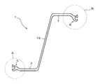
- FIG. 1 is an explanatory diagram of a Z-shaped steel sheet pile according to an embodiment of the present invention.
- FIG. 2 is an enlarged view of a portion A surrounded by a circle in FIG.
- FIG. 3 is an enlarged view of a portion B surrounded by a circle in FIG.
- FIG. 4 is an explanatory diagram of a state in which two Z-shaped steel sheet piles shown in FIG. 1 are connected.
- FIG. 5 is an explanatory view of a steel sheet pile wall formed by connecting the Z-shaped steel sheet piles shown in FIG.
- FIG. 6 is an explanatory view of a conventional Z-shaped steel sheet pile.
- the Z-shaped steel sheet pile 1 is formed at the first joint portion 5 formed at the distal end of the first flange portion 3 constituting the Z-shaped steel sheet pile 1 and at the distal end of the second flange portion 7.
- the steel sheet pile wall 27 (see FIG. 5) has a second joint part 9, and the Z-shaped steel sheet pile 1 is disposed adjacent to each other to engage and connect the first joint part 5 and the second joint part 9. Is a Z-shaped steel sheet pile.
- the 1st joint part 5 has the bulging part 11 in the front-end
- the Z-shaped steel sheet pile 1 has a first flange portion 3 on one end side of a web portion 16 arranged obliquely, a first joint portion 5 is formed at the tip of the first flange portion 3, and the other web portions 16. It has the 2nd flange part 7 in the end side, the 2nd coupling part 9 is formed in the front-end
- the first joint portion 5 and the second joint portion 9 include a joint body portion 17 formed so as to be continuous with the tip of the flange portion, and a main body formed so as to be divided into two branches from the joint body portion 17 and facing each other. It has a claw 13 and a sub claw 15.
- the base is thin and the bulging part 11 is formed in the front-end
- the bulging portion 11 of the main claw 13 in the present embodiment has a substantially rectangular shape, and the shape of the entire main claw 13 is T-shaped.
- the bulging portion 11 is not limited to a rectangular shape, and may be a circle or an ellipse.
- the outer bent angle of the connecting portion 19 between the T-shaped horizontal piece and the vertical piece in the main claw 13 is sharper than the inner bent angle. Since the inner bending angle is smooth, the joint interior 21 surrounded by the main claws 13 and the sub claws 15 in the joint portion has a smooth arc shape. Since the joint interior 21 has a smooth arc shape, the degree of freedom of rotation of the entire Z-shaped steel sheet pile 1 is increased when the joint portions are connected.
- the sub claw 15 has a thick root and a thickness that decreases toward the tip, and has a smooth curved shape as a whole.
- the main claw 13 of another joint portion connected to the inside of the joint 21 surrounded by the main claw 13 and the sub claw 15 is inserted. Since the bulging portion 11 is formed on the main claw 13, the main claw 13 does not come out from the gap between the main claw 13 and the sub claw 15.
- the first joint portion 5 and the second joint portion 9 are common in that the main claws 13 and the sub claws 15 are provided, but there are also differences. Therefore, hereinafter, the first joint portion 5 disposed on the left side in FIG. 1 and the second joint portion 9 disposed on the right side in FIG. 1 will be described separately.
- claw 15 is a steel sheet pile outer side in the connected joint part. Is to be arranged.
- the outer side of the steel sheet pile refers to the side opposite to the side where the web portion 16 is present with respect to the axis of the first flange portion 3, and the opposite side to the inner side of the steel sheet pile, ie, the central axis of the first flange portion 3. The side where the web part 16 is located.
- the first joint part 5 is arranged on the steel sheet pile inner side so that the sub claws 15 are arranged on the steel sheet pile outer side and the main claws 13 are opposed to the sub claws 15.
- the first joint portion 5 is connected to the first flange portion 3 through a first bent portion 23 that bends from the first flange portion 3 to the inside of the steel sheet pile. Since the first joint portion 5 is provided via the first bent portion 23, the outermost part of the steel sheet pile on the outer surface of the sub claw 15 disposed on the outer side of the steel sheet pile is the first flange portion 3. It is designed to be flush with the outer surface (see FIG. 2).
- claw 13 is arrange
- the 2nd joint part 9 is arrange
- the 2nd joint part 9 is connected with the 2nd flange part 7 via the 2nd bending part 25 bent from the 2nd flange part 7 to a steel sheet pile inner side.
- the second bent portion 25 has a longer extension distance to the inner side of the steel sheet pile than the first bent portion 23 formed on the first joint portion 5 side. Since the second joint portion 9 is provided via the second bent portion 25, the outermost part of the steel sheet pile on the outer surface of the main claw 13 disposed on the outer side of the steel sheet pile is the second flange portion 7. It arrange
- the joint portion (for example, the second joint portion 9) of the Z-shaped steel sheet pile 1 previously placed is subsequently placed.
- the joint part (for example, the 1st joint part 5) of the Z-shaped steel sheet pile 1 to be made is engaged and driven. Specifically, as shown in FIG. 2, the main claw 13 of the left joint is inserted into the joint inside 21 of the second joint part 9, and the main claw of the second joint part 9 is inserted into the joint inside 21 of the first joint part 5. It is made to engage so that 13 may be inserted.
- the Z-shaped steel sheet pile 1 is easily rotated by receiving the ground force as described above.
- the double-claw joint portion of the present embodiment has a high degree of freedom of rotation, so that excessive force does not act on the joint portion, and the joint portion is deformed at the time of placing. There is nothing.
- the double-claw joint has a high resistance to the tensile force, so that deformation is small. Therefore, a highly accurate steel sheet pile wall 27 can be formed.
- a steel sheet pile wall 27 is formed by connecting the first joint portion 5 and the second joint portion 9 of the Z-shaped steel sheet pile 1 (see FIG. 5).
- the secondary claws 15 of the first joint portion 5 are second on the second joint portion 9 side connected thereto.
- the outer surface of the flange portion 7 is prevented from protruding.
- the outer surfaces of the first flange portion 3 and the second flange portion 7 of the two connected Z-shaped steel sheet piles 1 are flush with each other.
- the joint portion of the present embodiment has a high degree of freedom of rotation, even when an earthquake force or the like is applied, excessive force does not act on the joint portion, and the joint portion is deformed or the like. There is nothing.
- the double-claw joint portion of the present embodiment is excellent in tensile strength, the joint portion is not deformed or the like when the Z-shaped steel sheet pile 1 receives a tensile force. Therefore, it is excellent in the water stoppage of the joint part.
- the Z-shaped steel sheet pile 1 of the present embodiment does not increase the weight of the steel material, and does not cause deformation or the like in the joint portion at the time of placing or after placing, so that a highly accurate steel sheet pile steel wall is provided. Can be built.
- the first joint portion 5 is provided at the tip of the first flange portion 3 via the first bent portion 23, and the second joint portion 9 is provided via the second bent portion 25.
- the 1st joint part 5 is provided in the front-end
Landscapes
- Engineering & Computer Science (AREA)
- Structural Engineering (AREA)
- Chemical & Material Sciences (AREA)
- Composite Materials (AREA)
- Life Sciences & Earth Sciences (AREA)
- General Life Sciences & Earth Sciences (AREA)
- Mining & Mineral Resources (AREA)
- Paleontology (AREA)
- Civil Engineering (AREA)
- General Engineering & Computer Science (AREA)
- Bulkheads Adapted To Foundation Construction (AREA)
Abstract
Description
本明細書において、Z形鋼矢板とは、斜めに配置されたウェブの両端に該ウェブに連続してフランジが形成され、全体形状が略Z形になった鋼矢板をいう。
U形鋼矢板、ハット形鋼矢板及びZ形鋼矢板の継手部は一般的にラルゼン型と言われるものが用いられている(特許文献1、2参照)。また、直線形鋼矢板には一般的には二重爪型と呼ばれるものが用いられており、特殊な例としてラルゼン型が用いられている(特許文献3参照)。
一方、ハット形鋼矢板同士やZ形鋼矢板同士を連結させて鋼矢板壁を構築する場合、継手部は構築後の鋼矢板壁最外縁に位置するため、鋼矢板単体の重心と鋼矢板壁の重心が一致している。したがって、鋼矢板壁が土圧等の作用荷重により曲げを受けても、継手部にずれが生じることはなく、継手効率を低減する必要がない。
したがって、U形鋼矢板に比べ、ハット形鋼矢板やZ形鋼矢板は、単位壁面積あたりの重量に対する断面性能が良く、経済性に優れた鋼矢板壁を構築することが可能である。
それに比べて、Z形鋼矢板は壁幅1mあたりの断面二次モーメントの種類が多く、その断面二次モーメントの最大のものはハット形鋼矢板の10倍程度のものもある。また、Z形鋼矢板を連結すればハット形状になることから、Z形鋼矢板を使用すれば、必要性能に応じて経済性、断面性能に優れた鋼矢板壁を構築することが可能である。
そこで、Z形鋼矢板の継手部について、従来用いられているラルゼン型のものが最適であるかについて検討したところ、以下のような問題があることが判明した。
鋼矢板同士を連結して鋼矢板壁を形成する際、通常、先行して打設された鋼矢板の継手部に後続の鋼矢板の継手部を嵌合させて打設する。この場合、後続の鋼矢板と先行する鋼矢板を完全に並行を保って打設できれば、継手部同士が接触することはない。
しかしながら、鋼矢板は打設中に地盤抵抗を受けるので、先行する鋼矢板と後続の鋼矢板の並行を保って打設することは難しい。そのため、鋼矢板が傾き、継手部同士が接触することで摩擦抵抗が生じ、継手部には種々の力が作用する。
ラルゼン型の継手部は引張り力や回転力が作用すると変形しやすい。継手部31に作用する上記の力によって、継手部31の開口部幅が閉じたり、開いたりする現象が生ずる可能性がある。継手部31の開口部幅が開きすぎると、鋼矢板同士が外れることもあり得るし、逆に継手部31の開口部幅が閉じすぎると後続の鋼矢板を打設できなくなることもあり得る。
他方、Z形鋼矢板では、その形状からU形鋼矢板やハット形鋼矢板のように土を拘束するような形状でないため、打設時に地盤抵抗によってZ形鋼矢板が回転等し易く、それ故に継手部に生ずる力が大きい。ラルゼン型の継手部では、上述したように引っ張り力や回転力に対して弱く、その一方で自由度が低いため、継手部が変形しやすく、上記のような問題が顕著に表れるという問題がある。
鋼矢板打設後においても、鋼矢板は地盤からの力を受け、特に地震が発生したような場合、引っ張り力に対して弱く、拘束力がつよいラルゼン型の継手部では、継手部に変形が生じやすいという問題がある。継手部に変形が生ずると、止水効果が低減するという問題が生ずる。
この点、継手部の変形を抑えるためには、継手部の厚さを厚くする方法が考えられる。
しかしながら、板厚を厚くすることは鋼材重量の増加につながるため、経済性が悪くなる。
また、本発明は、高精度な鋼矢板壁を得ることを目的としている。
前記第1継手部は、先端に膨出部を有し鋼矢板内側に配置される主爪と、該主爪に対向するように形成された鋼矢板外側に配置される副爪とを有する二重爪型の継手部であり、
前記第2継手部は、先端に膨出部を有し鋼矢板外側に配置される主爪と、該主爪に対向するように形成された鋼矢板内側に配置される副爪とを有する二重爪型の継手部であることを特徴とするものである。
前記第2継手部は、鋼矢板内側に向けて曲がる第2曲り部を介して前記フランジ部の先端に設けられており、前記第2曲り部を設けることにより、前記主爪の外面が前記副爪の厚み分以上の距離だけ鋼矢板内側に配置されていることを特徴とするものである。
第1継手部5は、先端に膨出部11を有し鋼矢板内側に配置される主爪13と、主爪13に対向するように形成された鋼矢板外側に配置される副爪15とを有する二重爪型の継手部である。
また、第2継手部9は、先端に膨出部11を有し鋼矢板外側に配置される主爪13と、主爪13に対向するように形成された鋼矢板内側に配置される副爪15とを有する二重爪型の継手部である。
以下詳細に説明する。
Z形鋼矢板1は、斜めに配置されたウェブ部16の一端側に第1フランジ部3を有し、第1フランジ部3の先端に第1継手部5が形成され、ウェブ部16の他端側に第2フランジ部7を有し、第2フランジ部7の先端に第2継手部9が形成され、全体として略Z形になっている。
第1継手部5と第2継手部9の基本形状は同じであるので、それを図2、図3に基づいて説明する。
第1継手部5と第2継手部9は、フランジ部の先端に連続するように形成された継手本体部17と、該継手本体部17から二股に分かれて互いに対向するように形成された主爪13と、副爪15を有している。
主爪13は、根元が細く先端に膨出部11が形成されている。本実施の形態における主爪13の膨出部11は略矩形をしており、主爪13全体の形状がT字状をしている。膨出部11は矩形状に限らず、円形、楕円形のようなものであってもよい。
主爪13と副爪15で囲まれる継手内部21に、これに連結される別の継手部の主爪13が挿入される。主爪13に膨出部11が形成されていることから、主爪13と副爪15との隙間から主爪13が抜け出さないようになっている。
第1継手部5は、第1継手部5と第2継手部9を連結して鋼矢板壁27(図5参照)を形成するときに、連結された継手部において副爪15が鋼矢板外側に配置されるものである。
なお、鋼矢板外側とは、第1フランジ部3の軸線に対してウェブ部16がある側と反対側をいい、鋼矢板内側とはその反対側、すなわち第1フランジ部3の中心軸に対してウェブ部16がある側をいう。
第2継手部9は、第1継手部5と第2継手部9を連結して鋼矢板壁27を形成するときに、連結された継手部において主爪13が鋼矢板外側に配置されるものである。
第2継手部9は、主爪13が鋼矢板外側に配置され、副爪15が主爪13に対向するように鋼矢板内側に配置されている。
第2継手部9は、第2フランジ部7から鋼矢板内側に曲がる第2曲り部25を介して第2フランジ部7に連結されている。第2曲り部25は、第1継手部5側に形成されている第1曲り部23よりも、鋼矢板内側への延出距離が大きくなるようになっている。
第2継手部9は、第2曲り部25を介して設けられていることにより、鋼矢板外側に配置されている主爪13の外面における最も鋼矢板外側の部位が、第2フランジ部7の外面よりも、距離Sだけ内側に配置されている(図3参照)。なお、距離Sは、副爪15の厚み以上の距離に設定されている。
打設に際して、前述したようにZ形鋼矢板1は地盤力を受けて回転しやすい。しかし、その場合において、本実施の形態の二重爪型の継手部は、回転の自由度が高いので、継手部に過度の力が作用することがなく、打設時に継手部が変形等することがない。また、二重爪型の継手部は引張り力に対する抵抗力が強いので、変形も少ない。それ故に、高精度の鋼矢板壁27を形成することができる。
Z形鋼矢板1の第1継手部5と第2継手部9を連結することによって鋼矢板壁27が形成される(図5参照)。第1継手部5と第2継手部9を連結した状態において(図4、図5参照)、第1継手部5の副爪15はこれに連結されている第2継手部9側の第2フランジ部7の外面よりも出っ張らないようになっている。この例では、連結された2枚のZ形鋼矢板1の第1フランジ部3と第2フランジ部7の外面が面一になっている。
連結された2枚のZ形鋼矢板1の第1フランジ部3及び第2フランジ部7の外面が面一になることで、当該部位に直接腹越し材を設置することが可能になる。仮に、連結部19において継手部が出っ張っていると、当該部位に例えば裏込めコンクリート等を介在させて腹起し材を設置しなければならないが、本実施の形態のものではそのような手間がなく作業性に優れている。
また、本実施の形態の二重爪型の継手部は、引張り強度に優れているので、その意味でもZ形鋼矢板1が引張り力を受けたときに継手部が変形等しない。それ故に、継手部の止水性に優れている。
3 第1フランジ部
5 第1継手部
7 第2フランジ部
9 第2継手部
11 膨出部
13 主爪
15 副爪
16 ウェブ部
17 継手本体部
19 連結部
21 継手内部
23 第1曲り部
25 第2曲り部
27 鋼矢板壁
29 従来形Z形鋼矢板
31 継手部
33 フランジ部
Claims (3)
- Z形鋼矢板を構成する一方のフランジ部の先端に形成された第1継手部と、他方のフランジ部の先端に形成された第2継手部とを有し、Z形鋼矢板を隣接配置して、前記第1継手部と前記第2継手部を係合させて連結することで鋼矢板壁を形成できるZ形鋼矢板であって、
前記第1継手部は、先端に膨出部を有し鋼矢板内側に配置される主爪と、該主爪に対向するように形成された鋼矢板外側に配置される副爪とを有する二重爪型の継手部であり、
前記第2継手部は、先端に膨出部を有し鋼矢板外側に配置される主爪と、該主爪に対向するように形成された鋼矢板内側に配置される副爪とを有する二重爪型の継手部であることを特徴とするZ形鋼矢板。 - 前記第1継手部は、鋼矢板内側に向けて曲がる第1曲り部を介して前記フランジ部の先端に設けられており、前記第1曲り部を設けることにより、前記副爪の外面がフランジ部の外面よりも鋼矢板外側に突出しないようになっており、
前記第2継手部は、鋼矢板内側に向けて曲がる第2曲り部を介して前記フランジ部の先端に設けられており、前記第2曲り部を設けることにより、前記主爪の外面が前記副爪の厚み分以上の距離だけ鋼矢板内側に配置されていることを特徴とする請求項1記載のZ形鋼矢板。 - 請求項1又は2に記載のZ形鋼矢板を連結して形成されたことを特徴とする鋼矢板壁。
Priority Applications (4)
| Application Number | Priority Date | Filing Date | Title |
|---|---|---|---|
| SG11201406542RA SG11201406542RA (en) | 2012-05-16 | 2012-05-16 | Z-shaped steel sheet pile, and steel sheet pile wall formed from said z-shaped steel sheet pile |
| CN201280072958.0A CN104271842A (zh) | 2012-05-16 | 2012-05-16 | Z形钢板桩、由该z形钢板桩形成的钢板桩壁 |
| KR1020147029683A KR20140139050A (ko) | 2012-05-16 | 2012-05-16 | Z형강 시트 파일, 당해 z형강 시트 파일로 형성된 강 시트 파일벽 |
| PCT/JP2012/063107 WO2013171910A1 (ja) | 2012-05-16 | 2012-05-16 | Z形鋼矢板、該z形鋼矢板で形成された鋼矢板壁 |
Applications Claiming Priority (1)
| Application Number | Priority Date | Filing Date | Title |
|---|---|---|---|
| PCT/JP2012/063107 WO2013171910A1 (ja) | 2012-05-16 | 2012-05-16 | Z形鋼矢板、該z形鋼矢板で形成された鋼矢板壁 |
Publications (1)
| Publication Number | Publication Date |
|---|---|
| WO2013171910A1 true WO2013171910A1 (ja) | 2013-11-21 |
Family
ID=49583350
Family Applications (1)
| Application Number | Title | Priority Date | Filing Date |
|---|---|---|---|
| PCT/JP2012/063107 WO2013171910A1 (ja) | 2012-05-16 | 2012-05-16 | Z形鋼矢板、該z形鋼矢板で形成された鋼矢板壁 |
Country Status (4)
| Country | Link |
|---|---|
| KR (1) | KR20140139050A (ja) |
| CN (1) | CN104271842A (ja) |
| SG (1) | SG11201406542RA (ja) |
| WO (1) | WO2013171910A1 (ja) |
Families Citing this family (2)
| Publication number | Priority date | Publication date | Assignee | Title |
|---|---|---|---|---|
| EP3362605A4 (en) * | 2015-10-13 | 2019-07-31 | Jarvie, John | IMPROVEMENTS ON SHORE WALLS, SUPPORT WALLS AND SIMILAR STRUCTURES WITH PENINSULATES |
| KR101667333B1 (ko) * | 2016-03-14 | 2016-10-18 | 손완규 | 신축 및 확장이 자유로운 시트파일 |
Citations (2)
| Publication number | Priority date | Publication date | Assignee | Title |
|---|---|---|---|---|
| JPS4920911A (ja) * | 1972-06-17 | 1974-02-23 | ||
| JP2002522665A (ja) * | 1998-07-31 | 2002-07-23 | コラス、ユーケー、リミテッド | メタルシートパイリング |
Family Cites Families (4)
| Publication number | Priority date | Publication date | Assignee | Title |
|---|---|---|---|---|
| GB378412A (en) * | 1930-06-24 | 1932-08-04 | Charles Marie Pierre Costes | Improvements relating to sheet-piling units and assemblies composed thereof |
| DE69631950T2 (de) * | 1995-09-29 | 2005-02-10 | Sumitomo Metal Industries, Ltd. | Assymetrische stahlbohle und verfahren zu deren herstellung |
| US6715964B2 (en) * | 2000-07-28 | 2004-04-06 | Peratrovich, Nottingham & Drage, Inc. | Earth retaining system such as a sheet pile wall with integral soil anchors |
| EP1420116B1 (en) * | 2002-11-15 | 2017-05-31 | Nippon Steel & Sumitomo Metal Corporation | Metal sheet pile |
-
2012
- 2012-05-16 KR KR1020147029683A patent/KR20140139050A/ko not_active Application Discontinuation
- 2012-05-16 CN CN201280072958.0A patent/CN104271842A/zh active Pending
- 2012-05-16 WO PCT/JP2012/063107 patent/WO2013171910A1/ja active Application Filing
- 2012-05-16 SG SG11201406542RA patent/SG11201406542RA/en unknown
Patent Citations (2)
| Publication number | Priority date | Publication date | Assignee | Title |
|---|---|---|---|---|
| JPS4920911A (ja) * | 1972-06-17 | 1974-02-23 | ||
| JP2002522665A (ja) * | 1998-07-31 | 2002-07-23 | コラス、ユーケー、リミテッド | メタルシートパイリング |
Also Published As
| Publication number | Publication date |
|---|---|
| SG11201406542RA (en) | 2014-11-27 |
| KR20140139050A (ko) | 2014-12-04 |
| CN104271842A (zh) | 2015-01-07 |
Similar Documents
| Publication | Publication Date | Title |
|---|---|---|
| JP4903744B2 (ja) | 既設の鋼矢板の補強構造、既設の鋼矢板の補強用部材 | |
| WO2015140889A1 (ja) | 柱構造及びベース部材 | |
| WO2013171910A1 (ja) | Z形鋼矢板、該z形鋼矢板で形成された鋼矢板壁 | |
| WO2013171909A1 (ja) | 組合せ鋼製壁 | |
| JP5782729B2 (ja) | Z形鋼矢板、該z形鋼矢板で形成された鋼矢板壁 | |
| JP5114741B2 (ja) | ハット形鋼矢板 | |
| JP4014216B2 (ja) | 構造材、接続構造体及び構造材の接続方法 | |
| JP6394180B2 (ja) | 鋼管矢板の継手構造 | |
| JP2011157755A (ja) | 鋼製セグメント及び合成セグメント | |
| JP2009235672A (ja) | ハット形鋼矢板 | |
| JP5194782B2 (ja) | ハット形鋼矢板 | |
| JP2017066702A (ja) | 鋼矢板の縦継構造及び鋼矢板壁 | |
| KR20090006672A (ko) | 말뚝과 이 말뚝을 이용한 옹벽 | |
| RU59083U1 (ru) | Шпунтовая стенка из сварных трубчатых свай | |
| JP5257470B2 (ja) | 組合せ鋼製壁 | |
| JP5737058B2 (ja) | H形鋼矢板 | |
| TWI516659B (zh) | Z-shaped steel sheet pile, the Z-shaped steel sheet pile formed by the steel sheet pile wall | |
| JP5772658B2 (ja) | ハット型鋼矢板およびハット型鋼矢板を用いた構造体 | |
| JP5079731B2 (ja) | 表面板と主桁を連結する合成セグメント、合成セグメントの製造方法およびトンネル | |
| JP5633502B2 (ja) | 壁体構造 | |
| WO2018155695A1 (ja) | 矢板 | |
| JP3911261B2 (ja) | 圧延鋼矢板 | |
| JP6089929B2 (ja) | 鋼矢板及び鋼矢板壁 | |
| WO2018117269A1 (ja) | ハット形鋼矢板 | |
| JP6296199B1 (ja) | ハット形鋼矢板及び壁体 |
Legal Events
| Date | Code | Title | Description |
|---|---|---|---|
| 121 | Ep: the epo has been informed by wipo that ep was designated in this application |
Ref document number: 12877059 Country of ref document: EP Kind code of ref document: A1 |
|
| ENP | Entry into the national phase |
Ref document number: 20147029683 Country of ref document: KR Kind code of ref document: A |
|
| NENP | Non-entry into the national phase |
Ref country code: DE |
|
| 122 | Ep: pct application non-entry in european phase |
Ref document number: 12877059 Country of ref document: EP Kind code of ref document: A1 |
|
| NENP | Non-entry into the national phase |
Ref country code: JP |