WO2013171909A1 - Mur en acier combiné - Google Patents
Mur en acier combiné Download PDFInfo
- Publication number
- WO2013171909A1 WO2013171909A1 PCT/JP2012/063103 JP2012063103W WO2013171909A1 WO 2013171909 A1 WO2013171909 A1 WO 2013171909A1 JP 2012063103 W JP2012063103 W JP 2012063103W WO 2013171909 A1 WO2013171909 A1 WO 2013171909A1
- Authority
- WO
- WIPO (PCT)
- Prior art keywords
- steel sheet
- sheet pile
- shaped steel
- joint
- claw
- Prior art date
Links
Images


Classifications
-
- E—FIXED CONSTRUCTIONS
- E02—HYDRAULIC ENGINEERING; FOUNDATIONS; SOIL SHIFTING
- E02D—FOUNDATIONS; EXCAVATIONS; EMBANKMENTS; UNDERGROUND OR UNDERWATER STRUCTURES
- E02D5/00—Bulkheads, piles, or other structural elements specially adapted to foundation engineering
- E02D5/02—Sheet piles or sheet pile bulkheads
- E02D5/03—Prefabricated parts, e.g. composite sheet piles
- E02D5/04—Prefabricated parts, e.g. composite sheet piles made of steel
- E02D5/06—Fitted piles or other elements specially adapted for closing gaps between two sheet piles or between two walls of sheet piles
-
- E—FIXED CONSTRUCTIONS
- E02—HYDRAULIC ENGINEERING; FOUNDATIONS; SOIL SHIFTING
- E02D—FOUNDATIONS; EXCAVATIONS; EMBANKMENTS; UNDERGROUND OR UNDERWATER STRUCTURES
- E02D5/00—Bulkheads, piles, or other structural elements specially adapted to foundation engineering
- E02D5/02—Sheet piles or sheet pile bulkheads
- E02D5/03—Prefabricated parts, e.g. composite sheet piles
- E02D5/04—Prefabricated parts, e.g. composite sheet piles made of steel
- E02D5/08—Locking forms; Edge joints; Pile crossings; Branch pieces
Definitions
- the present invention relates to a combined steel wall used for harbor / river bank protection, mountain retaining, and deadline construction in the field of civil engineering and construction.
- a Z-shaped steel sheet pile means the steel sheet pile in which the flange was continuously formed in the both ends of the web arrange
- Patent Document 1 As a steel wall used for harbor and river revetment, mountain retaining, and deadline construction in the civil engineering and construction field, there is a combined steel wall combining a U-shaped steel sheet pile and an H-shaped steel (see Patent Document 1).
- the combined steel sheet pile described in Patent Document 1 is “U formed in a substantially U-shaped cross section from a web portion, a flange portion provided at both ends of the web portion, and an arm portion provided at one end of the flange portion. It is formed from a section steel sheet pile and an H-section steel that is installed with one flange fixed to the web portion on one side of the U-shaped steel sheet pile "(see claim 1 of Patent Document 1).
- Patent Document 1 The combined steel wall of Patent Document 1 is such that a web portion of a U-shaped steel sheet pile and a flange of an H-shaped steel are fixed in advance by welding or the like, and are sequentially placed on the ground. Therefore, there is a trouble that the U-shaped steel sheet pile and the H-shaped steel must be fixed in advance. Moreover, it has a complicated shape in which a U-shaped steel sheet pile and an H-shaped steel are fixed in advance, and since there is a large cross section, there is also a problem that ground resistance is large and placement is difficult. Moreover, since it is a shape which fixes the flange of a H-section steel to the web part of a U-shaped steel sheet pile, there also exists a problem that the steel weight per unit length is large and material cost becomes high.
- H-shaped steel is connected in parallel between the joint portion and the joint portion of the U-shaped steel sheet pile, the hat-shaped steel sheet pile, or the Z-shaped steel sheet pile
- It is called a Lalsen type and is not a shape that can be directly connected to other steel members such as H-shaped steel. Therefore, to construct a combined steel wall by connecting a conventional Z-shaped steel sheet pile or the like and an H-shaped steel in parallel, in order to connect the Z-shaped steel sheet pile or the like and the H-shaped steel, the H-shaped Z-shaped steel sheet pile or the like
- a separate connector is required to connect the two to steel.
- An object of the present invention is to provide a combined steel wall formed by connecting a Z-shaped steel sheet pile and an H-shaped steel without using a separate member called a connector.
- the combined steel wall according to the present invention has a flange portion at both ends of a web portion, and a Z-shaped steel sheet pile having a joint portion at each end of the flange portion and an H-shaped steel.
- a combined steel wall composed of: A flange portion of H-shaped steel is disposed along the axial direction of the flange portion of the Z-shaped steel sheet pile, a Z-shaped steel sheet pile is disposed along the axial direction of the flange portion of the H-shaped steel, and the Z shape It has a combination part arranged in the order of Z-shaped steel sheet pile, H-shaped steel, Z-shaped steel sheet pile in which the joint part of the steel sheet pile and the end of the flange part of the H-shaped steel are directly connected It is.
- the joint portion of the Z-shaped steel sheet pile includes a first joint portion formed at the tip of one flange portion constituting the Z-shaped steel sheet pile, and the other joint portion.
- the first joint portion has a bulge at the tip and a main claw disposed on the inner side of the steel sheet pile, and is formed to face the main claw.
- a double-claw joint having a sub-claw arranged on the outer side of the steel sheet pile
- the second joint portion has a main claw having a bulging portion at the tip and disposed on the outer side of the steel sheet pile, and a secondary claw disposed on the inner side of the steel sheet pile formed to face the main claw.
- the flange portion of the H-shaped steel is characterized in that a protrusion projecting in the thickness direction of the flange portion is provided at an end portion thereof.
- the first joint portion has a bulge at the tip and a main claw disposed inside the steel sheet pile, and is formed so as to face the main claw.
- a double-claw joint having a sub-claw arranged on the outer side of the steel sheet pile
- the second joint portion has a main claw having a bulging portion at the tip and disposed on the outer side of the steel sheet pile, and a secondary claw disposed on the inner side of the steel sheet pile formed to face the main claw.
- the flange portion of the H-shaped steel is provided with a groove portion at an end portion thereof.
- the first joint portion is provided at the tip of the flange portion via a first bent portion that bends toward the inside of the steel sheet pile.
- the second joint portion is provided at the front end of the flange portion via a second bent portion that is bent toward the inside of the steel sheet pile, and by providing the second bent portion, the outer surface of the main claw is provided on the sub-joint.
- the steel sheet pile is arranged by a distance equal to or greater than the thickness of the nail.
- the flange portion of the H-shaped steel is arranged along the axial direction of the flange portion of the Z-shaped steel sheet pile, and Z is aligned along the axial direction of the flange portion of the H-shaped steel.
- a shaped steel sheet pile is arranged, and has a combination part of a Z-shaped steel sheet pile, H-shaped steel, and Z-shaped steel sheet pile in which a joint portion of the Z-shaped steel sheet pile and an end portion of the flange portion of the H-shaped steel are directly connected. . Therefore, it is not necessary to fix the Z-shaped steel sheet pile and the H-shaped steel in advance, and the workability is excellent because each member can be placed on the ground.
- edge part of the flange part of H-section steel is directly connected with the joint part of Z-shaped steel sheet pile. Therefore, it is not necessary to use a separate connector or the like to connect the Z-shaped steel sheet pile and the H-shaped steel, which is excellent in workability and reduces the material cost.
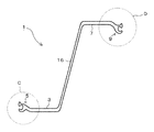
- FIG. 1 is an explanatory view of a combined steel wall according to an embodiment of the present invention.
- FIG. 2 is an enlarged view of a portion A surrounded by a circle in FIG.
- FIG. 3 is an explanatory view of a Z-shaped steel sheet pile constituting the combined steel wall according to one embodiment of the present invention.
- 4 is an enlarged view of a portion C surrounded by a circle in FIG.
- FIG. 5 is an enlarged view of a portion D surrounded by a circle in FIG.
- FIG. 6 is an explanatory diagram of the H-section steel constituting the combined steel wall according to one embodiment of the present invention.
- FIG. 7 is an explanatory view of another aspect of the H-shaped steel constituting the combined steel wall according to one embodiment of the present invention.
- the combined steel wall 1 has a flange portion at both ends of a web portion, and a Z-shaped steel sheet pile 2 having a joint portion at each end of the flange portion and an H-shaped steel 4 are connected.
- the flange portion of the H-shaped steel 4 is arranged along the axial direction of the flange portion of the Z-shaped steel sheet pile 2, and the axial direction of the flange portion of the H-shaped steel 4.
- Z-shaped steel sheet pile 2 is arranged along the Z-shaped steel sheet pile 2 and the joint of the Z-shaped steel sheet pile 2 and the end of the flange portion of the H-shaped steel 4 are directly connected.
- the Z-shaped steel sheet piles 2 are connected to each other at the end of the combined position of the Z-shaped steel sheet pile 2, the H-shaped steel 4, and the Z-shaped steel sheet pile 2. It will be.
- the Z-shaped steel sheet pile 2 and the H-shaped steel 4 constituting the combined steel wall 1 will be described in detail.
- the Z-shaped steel sheet pile 2 includes a first joint portion 5 formed at the tip of the first flange portion 3 constituting the Z-shaped steel sheet pile 2, and a second flange portion.
- Z having a second joint portion 9 formed at the tip of 7, Z-shaped steel sheet piles 2 can be arranged adjacent to each other, and the first joint portion 5 and the second joint portion 9 can be engaged and connected. It is a shaped steel sheet pile.
- the 1st joint part 5 has the bulging part 11 in the front-end
- the 2nd coupling part 9 has the bulging part 11 in the front-end
- the details of the Z-shaped steel sheet pile 2 will be described in more detail by dividing them into an overall shape and a joint part.
- the Z-shaped steel sheet pile 2 has a first flange portion 3 on one end side of a web portion 16 disposed obliquely, and a first joint portion 5 is formed at the tip of the first flange portion 3. It has the 2nd flange part 7 in the end side, the 2nd coupling part 9 is formed in the front-end
- the first joint part 5 and the second joint part 9 are divided into a joint body part 17 formed so as to be continuous with the front end of the flange part, and the joint body part 17 into two branches.
- the main claw 13 and the sub claw 15 are formed so as to face each other.
- the base is thin and the bulging part 11 is formed in the front-end
- the bulging portion 11 of the main claw 13 in the present embodiment has a substantially rectangular shape, and the shape of the entire main claw 13 is T-shaped.
- the bulging portion 11 is not limited to a rectangular shape, and may be a circle or an ellipse.
- the outer bent angle of the connecting portion 19 between the T-shaped horizontal piece and the vertical piece in the main claw 13 is sharper than the inner bent angle. Since the inner bending angle is smooth, the joint interior 21 surrounded by the main claws 13 and the sub claws 15 in the joint portion has a smooth arc shape. Since the joint interior 21 has a smooth arc shape, the degree of freedom of rotation of the entire Z-shaped steel sheet pile 2 is increased when the joint portions are connected.
- the sub claw 15 has a thick root and a thickness that decreases toward the tip, and has a smooth curved shape as a whole.
- the main claw 13 of the joint portion connected to the inside of the joint 21 surrounded by the main claw 13 and the sub claw 15 is inserted. Since the bulging portion 11 is formed on the main claw 13, the main claw 13 does not come out from the gap between the main claw 13 and the sub claw 15.
- the first joint portion 5 and the second joint portion 9 are common in that they have the main claws 13 and the sub claws 15 described above, but there are also differences.
- positioned at the right side in FIG. 3 are demonstrated separately.
- claw 15 is a steel sheet pile in the connected joint part. It is arranged outside.
- the outer side of the steel sheet pile refers to the side opposite to the side where the web portion 16 is present with respect to the axis of the first flange portion 3, and the opposite side to the inner side of the steel sheet pile, ie, the central axis of the first flange portion 3. The side where the web part 16 is located.
- the first joint part 5 is arranged on the steel sheet pile inner side so that the sub claws 15 are arranged on the steel sheet pile outer side and the main claws 13 are opposed to the sub claws 15.
- the first joint portion 5 is connected to the first flange portion 3 through a first bent portion 23 that bends from the first flange portion 3 to the inside of the steel sheet pile. Since the first joint portion 5 is provided via the first bent portion 23, the outermost part of the steel sheet pile on the outer surface of the sub claw 15 disposed on the outer side of the steel sheet pile is the first flange portion 3. It is designed to be flush with the outer surface (see FIGS. 2 and 4).
- claw 13 is arrange
- the 2nd joint part 9 is arrange
- the 2nd joint part 9 is connected with the 2nd flange part 7 via the 2nd bending part 25 bent from the 2nd flange part 7 to a steel sheet pile inner side.
- the second bent portion 25 has a longer extension distance to the inner side of the steel sheet pile than the first bent portion 23 formed on the first joint portion 5 side. Since the second joint portion 9 is provided via the second bent portion 25, the outermost part of the steel sheet pile on the outer surface of the main claw 13 disposed on the outer side of the steel sheet pile is the second flange portion 7. It arrange
- the distance S is set to a distance that is equal to or greater than the thickness of the auxiliary nail 15.
- the H-shaped steel 4 has a web portion 35 and a flange portion 37, and faces outward at the tip of the flange portion 37 (opposite to the web portion 35 with respect to the axis of the flange portion 37).
- a protruding projection 39 is provided. As shown in FIG. 1, the protrusion 39 is formed when the tip of the flange portion 37 of the H-shaped steel 4 is inserted into the first joint portion 5 or the second joint portion 9 of the Z-shaped steel sheet pile 2. Engages with the second joint portion 9.
- the projection 39 projects outward (on the opposite side to the web portion 35 with respect to the axis of the flange portion 37) as in the present embodiment, and also on the outside and inside (with respect to the axis of the flange portion 37). And the same projecting side as the web portion 35) or projecting only inward.
- the construction method of the combined steel wall 1 will be described.
- the Z-shaped steel sheet pile 2 on the left side in the figure is placed, and then the tip of the flange portion 37 of the H-shaped steel 4 is placed inside the joint of the first joint portion 5 of the Z-shaped steel sheet pile 2 ( The H-section steel 4 is driven in such a manner that the tip on the left side in the figure is inserted.
- the Z-shaped steel sheet pile 2 is made so that the other tip (the tip on the right side in the figure) of the flange portion 37 of the H-shaped steel 4 is inserted into the joint of the first joint portion 5 of the Z-shaped steel sheet pile 2. To cast.
- the Z-shaped steel sheet pile 2 is driven so that the second joint portion 9 of the cast Z-shaped steel sheet pile 2 and the first joint portion 5 of another Z-shaped steel sheet pile 2 are engaged.
- the tip of the flange portion 37 of the H-shaped steel 4 (the tip on the left side in the figure) is inserted into the joint of the second joint portion 9 of the cast Z-shaped steel sheet pile 2 so that the H-shaped steel 4 To cast.
- the Z-shaped steel sheet pile 2 is made so that the other tip (the right tip in the drawing) of the flange portion 37 of the H-shaped steel 4 is inserted into the joint of the second joint portion 9 of the Z-shaped steel sheet pile 2.
- the combined steel wall 1 is constructed.
- the double-claw joint portion of the present embodiment has a high degree of freedom in rotation.
- the joint portion is not deformed at the time of placing.
- the double-claw joint has a high resistance to the tensile force, so that deformation is small. Therefore, the highly accurate combination steel wall 1 can be formed.
- the joint portion of the present embodiment has a high degree of freedom of rotation, even when an earthquake force or the like is applied, excessive force does not act on the joint portion, and the joint portion is deformed or the like. There is nothing. Further, since the double-claw joint portion of the present embodiment is excellent in tensile strength, the joint portion is not deformed or the like when the Z-shaped steel sheet pile 2 receives a tensile force. Therefore, it is excellent in the water stoppage of the joint part.
- the combined steel wall 1 of the present embodiment can be constructed by directly connecting the Z-shaped steel sheet pile 2 and the H-shaped steel 4 without using a separate member called a connector.
- a plurality of Z-shaped steel sheet piles 2 are arranged next to the combination parts arranged in the order of Z-shaped steel sheet pile 2, H-shaped steel 4, and Z-shaped steel sheet pile 2, and then again the Z-shaped steel sheet pile. It arrange
- the groove part 40 may be provided on the outer side (the side opposite to the web part 35 with respect to the axis of the flange part 37), or the outer side and the inner side (with respect to the axis of the flange part 37). It may be provided both on the same side as the web portion 35, or may be provided only inside.
Landscapes
- Engineering & Computer Science (AREA)
- Structural Engineering (AREA)
- Chemical & Material Sciences (AREA)
- Composite Materials (AREA)
- Life Sciences & Earth Sciences (AREA)
- General Life Sciences & Earth Sciences (AREA)
- Mining & Mineral Resources (AREA)
- Paleontology (AREA)
- Civil Engineering (AREA)
- General Engineering & Computer Science (AREA)
- Bulkheads Adapted To Foundation Construction (AREA)
Abstract
Priority Applications (4)
| Application Number | Priority Date | Filing Date | Title |
|---|---|---|---|
| SG11201406539SA SG11201406539SA (en) | 2012-05-16 | 2012-05-16 | Combined steel wall |
| KR1020147029682A KR20140139049A (ko) | 2012-05-16 | 2012-05-16 | 조합 강제 벽 |
| PCT/JP2012/063103 WO2013171909A1 (fr) | 2012-05-16 | 2012-05-16 | Mur en acier combiné |
| CN201280073163.1A CN104285010B (zh) | 2012-05-16 | 2012-05-16 | 组合钢板墙 |
Applications Claiming Priority (1)
| Application Number | Priority Date | Filing Date | Title |
|---|---|---|---|
| PCT/JP2012/063103 WO2013171909A1 (fr) | 2012-05-16 | 2012-05-16 | Mur en acier combiné |
Publications (1)
| Publication Number | Publication Date |
|---|---|
| WO2013171909A1 true WO2013171909A1 (fr) | 2013-11-21 |
Family
ID=49583349
Family Applications (1)
| Application Number | Title | Priority Date | Filing Date |
|---|---|---|---|
| PCT/JP2012/063103 WO2013171909A1 (fr) | 2012-05-16 | 2012-05-16 | Mur en acier combiné |
Country Status (4)
| Country | Link |
|---|---|
| KR (1) | KR20140139049A (fr) |
| CN (1) | CN104285010B (fr) |
| SG (1) | SG11201406539SA (fr) |
| WO (1) | WO2013171909A1 (fr) |
Cited By (3)
| Publication number | Priority date | Publication date | Assignee | Title |
|---|---|---|---|---|
| CN106062281A (zh) * | 2014-03-03 | 2016-10-26 | 杰富意钢铁株式会社 | 直线形钢板桩、使用了该直线形钢板桩的结构物的加强结构及加强方法 |
| CN108729450A (zh) * | 2018-05-30 | 2018-11-02 | 中水电第十工程局(郑州)有限公司 | 一种管道工程钢板桩支护方法 |
| CN111074880A (zh) * | 2018-10-19 | 2020-04-28 | J.D.菲尔兹公司 | 组合墙打桩系统 |
Families Citing this family (1)
| Publication number | Priority date | Publication date | Assignee | Title |
|---|---|---|---|---|
| CN105064379B (zh) * | 2015-08-29 | 2017-02-22 | 青岛蓝天创先科技服务有限公司 | 一种h型钢基坑支护装置及方法 |
Citations (2)
| Publication number | Priority date | Publication date | Assignee | Title |
|---|---|---|---|---|
| JP2005307740A (ja) * | 2004-04-23 | 2005-11-04 | Pilepro Llc | 支持要素に矢板を接続する長尺の連結体 |
| US20110076103A1 (en) * | 2006-09-01 | 2011-03-31 | Rob Wendt | Barrier wall made of sheet-pile components |
Family Cites Families (7)
| Publication number | Priority date | Publication date | Assignee | Title |
|---|---|---|---|---|
| JP3488232B1 (ja) * | 2002-11-15 | 2004-01-19 | 新日本製鐵株式会社 | 圧延鋼矢板 |
| JP4384551B2 (ja) * | 2004-06-07 | 2009-12-16 | 新日本製鐵株式会社 | 鋼矢板 |
| DE202006020608U1 (de) * | 2006-01-17 | 2009-03-12 | Arcelormittal Commercial Rps S.A.R.L. | Spundbohle in Doppel-T-Form |
| DE102007020747A1 (de) * | 2007-05-03 | 2008-11-13 | Pilepro Llc | Anordnung aus mehreren Spundwandkomponenten sowie Anschweißprofil hierfür |
| CN102282315B (zh) * | 2009-01-16 | 2015-10-07 | 新日铁住金株式会社 | 组合钢板桩、由组合钢板桩构成的板桩壁和组合钢板桩的选定方法 |
| JP5282984B2 (ja) * | 2010-03-12 | 2013-09-04 | 新日鐵住金株式会社 | 鋼製連続壁の施工方法および鋼製連続壁 |
| CN201915389U (zh) * | 2010-12-17 | 2011-08-03 | 南京万汇新材料科技有限公司 | H形与z形组合钢板桩 |
-
2012
- 2012-05-16 WO PCT/JP2012/063103 patent/WO2013171909A1/fr active Application Filing
- 2012-05-16 SG SG11201406539SA patent/SG11201406539SA/en unknown
- 2012-05-16 CN CN201280073163.1A patent/CN104285010B/zh active Active
- 2012-05-16 KR KR1020147029682A patent/KR20140139049A/ko not_active Application Discontinuation
Patent Citations (2)
| Publication number | Priority date | Publication date | Assignee | Title |
|---|---|---|---|---|
| JP2005307740A (ja) * | 2004-04-23 | 2005-11-04 | Pilepro Llc | 支持要素に矢板を接続する長尺の連結体 |
| US20110076103A1 (en) * | 2006-09-01 | 2011-03-31 | Rob Wendt | Barrier wall made of sheet-pile components |
Cited By (3)
| Publication number | Priority date | Publication date | Assignee | Title |
|---|---|---|---|---|
| CN106062281A (zh) * | 2014-03-03 | 2016-10-26 | 杰富意钢铁株式会社 | 直线形钢板桩、使用了该直线形钢板桩的结构物的加强结构及加强方法 |
| CN108729450A (zh) * | 2018-05-30 | 2018-11-02 | 中水电第十工程局(郑州)有限公司 | 一种管道工程钢板桩支护方法 |
| CN111074880A (zh) * | 2018-10-19 | 2020-04-28 | J.D.菲尔兹公司 | 组合墙打桩系统 |
Also Published As
| Publication number | Publication date |
|---|---|
| CN104285010B (zh) | 2016-01-20 |
| CN104285010A (zh) | 2015-01-14 |
| SG11201406539SA (en) | 2014-11-27 |
| KR20140139049A (ko) | 2014-12-04 |
Similar Documents
| Publication | Publication Date | Title |
|---|---|---|
| US9506212B2 (en) | Universal connecting element for sheet pile wall components | |
| EP2672012B1 (fr) | Structure de liaison pour relier un pieu tubulaire en acier et un tube externe en acier | |
| EP2554751A1 (fr) | Structure de paroi reliée constituée de palplanches à pieux tubulaires et palfeuille, et procédé de construction associé | |
| WO2013171909A1 (fr) | Mur en acier combiné | |
| JP5257470B2 (ja) | 組合せ鋼製壁 | |
| JP5521277B2 (ja) | ハット形鋼矢板 | |
| JP2006241816A (ja) | 地中連続壁 | |
| JP4014216B2 (ja) | 構造材、接続構造体及び構造材の接続方法 | |
| JP2017066702A (ja) | 鋼矢板の縦継構造及び鋼矢板壁 | |
| JP6714307B2 (ja) | 既設鋼矢板壁の補強工法 | |
| JP2014020129A (ja) | 鋼矢板及び鋼矢板壁体 | |
| JP5114731B2 (ja) | 地中連続壁体の設計方法 | |
| JP6515293B2 (ja) | 鋼矢板壁 | |
| JP5782729B2 (ja) | Z形鋼矢板、該z形鋼矢板で形成された鋼矢板壁 | |
| WO2013171910A1 (fr) | Palfeuille en forme de z, et mur à palfeuille formé à partir de ladite palfeuille en forme de z | |
| JP5637657B2 (ja) | 土留壁及びその補強方法 | |
| JP2013199746A (ja) | 土留壁 | |
| JP5737058B2 (ja) | H形鋼矢板 | |
| SG189307A1 (en) | Steel sheet pile and steel sheet pile wall formed of such steel sheet piles | |
| JP5079731B2 (ja) | 表面板と主桁を連結する合成セグメント、合成セグメントの製造方法およびトンネル | |
| JP6489055B2 (ja) | 既設鋼矢板壁の補強構造および補強工法 | |
| CN211171920U (zh) | 一种塑钢板桩 | |
| TWI480448B (zh) | Combination of steel wall | |
| JP2013112982A (ja) | 壁体構造 | |
| TWI516659B (zh) | Z-shaped steel sheet pile, the Z-shaped steel sheet pile formed by the steel sheet pile wall |
Legal Events
| Date | Code | Title | Description |
|---|---|---|---|
| 121 | Ep: the epo has been informed by wipo that ep was designated in this application |
Ref document number: 12876918 Country of ref document: EP Kind code of ref document: A1 |
|
| ENP | Entry into the national phase |
Ref document number: 20147029682 Country of ref document: KR Kind code of ref document: A |
|
| NENP | Non-entry into the national phase |
Ref country code: DE |
|
| 122 | Ep: pct application non-entry in european phase |
Ref document number: 12876918 Country of ref document: EP Kind code of ref document: A1 |
|
| NENP | Non-entry into the national phase |
Ref country code: JP |