WO2015105021A1 - ゴルフクラブ用シャフト及びゴルフクラブ - Google Patents
ゴルフクラブ用シャフト及びゴルフクラブ Download PDFInfo
- Publication number
- WO2015105021A1 WO2015105021A1 PCT/JP2014/084475 JP2014084475W WO2015105021A1 WO 2015105021 A1 WO2015105021 A1 WO 2015105021A1 JP 2014084475 W JP2014084475 W JP 2014084475W WO 2015105021 A1 WO2015105021 A1 WO 2015105021A1
- Authority
- WO
- WIPO (PCT)
- Prior art keywords
- golf club
- shaft
- club shaft
- resin layer
- filler
- Prior art date
Links
Images


Classifications
-
- A—HUMAN NECESSITIES
- A63—SPORTS; GAMES; AMUSEMENTS
- A63B—APPARATUS FOR PHYSICAL TRAINING, GYMNASTICS, SWIMMING, CLIMBING, OR FENCING; BALL GAMES; TRAINING EQUIPMENT
- A63B53/00—Golf clubs
- A63B53/10—Non-metallic shafts
-
- A—HUMAN NECESSITIES
- A63—SPORTS; GAMES; AMUSEMENTS
- A63B—APPARATUS FOR PHYSICAL TRAINING, GYMNASTICS, SWIMMING, CLIMBING, OR FENCING; BALL GAMES; TRAINING EQUIPMENT
- A63B60/00—Details or accessories of golf clubs, bats, rackets or the like
-
- A—HUMAN NECESSITIES
- A63—SPORTS; GAMES; AMUSEMENTS
- A63B—APPARATUS FOR PHYSICAL TRAINING, GYMNASTICS, SWIMMING, CLIMBING, OR FENCING; BALL GAMES; TRAINING EQUIPMENT
- A63B2209/00—Characteristics of used materials
- A63B2209/02—Characteristics of used materials with reinforcing fibres, e.g. carbon, polyamide fibres
Definitions
- the present invention relates to a golf club shaft and a golf club.
- This application claims priority based on Japanese Patent Application No. 2014-1896 filed in Japan on January 8, 2014, the contents of which are incorporated herein by reference.
- the behavior of the shaft during the swing has a great influence on the flight distance and the feeling felt by the golfer. For this reason, research has been conducted on a golf club shaft for increasing the flight distance and obtaining a favorable feeling.
- the flight distance of a golf ball is determined by the initial velocity, launch angle, and spin rate of the ball.
- Patent Document 1 a stable launch angle and a spin amount are obtained by increasing the rigidity on the small-diameter end side of the golf shaft and decreasing the rigidity on the large-diameter side adjacent thereto.
- this method has not yet achieved an increase in flight distance.
- the initial velocity of the ball In order to achieve an increase in the flight distance of the hit ball, it is necessary to increase the initial velocity of the ball. As a means for this, it is conceivable to increase the head weight.
- the head weight is simply increased, the moment of inertia of the golf club increases and the weight of the golf club is felt during a swing, so the ease of swinging the golf club decreases.
- a so-called high balance shaft called a shaft with the center of gravity brought close to the hand. This reduces the weight felt during a swing even when the head weight is increased by bringing the center of gravity of the shaft closer to the hand side.
- the ratio (Lg / Ls) is 0.52 or more and 0.65 or less when the total length of the shaft is Ls and the distance from the tip end of the shaft to the center of gravity G of the shaft is Lg.
- a shaft has been proposed.
- the high balance in Patent Document 2 is presumed to be due to the thickening of the grip side of the shaft. In this case, the bending rigidity on the grip side of the shaft is also increased. Feeling optimization was sometimes difficult.
- this thickening also increases the weight of the shaft, it is necessary to reduce the thickness on the head side in order to avoid an increase in the weight of the entire shaft, but this may cause a reduction in the strength of the shaft. .
- the present invention has been made in view of the above problems, can widely correspond to the characteristics of the head to be mounted, the level and preference of the golfer, and can maintain ease of swinging even when a heavy weight head is mounted, It is an object of the present invention to provide a golf club shaft that can obtain a favorable feeling even when the target golfer is a professional golfer or a general expert and can increase the flight distance of the hit ball.
- an embodiment of the present invention employs the following configuration.
- a golf club shaft composed of a plurality of fiber reinforced resin layers, wherein a heavy material having a specific gravity of 7 or more is within a range of 0 to 400 mm from the grip side (large diameter) end of the golf club shaft.
- Ls the total length of the golf club shaft
- Lg the distance from the head side (thin diameter) end to the center of gravity of the golf club shaft
- Lg / Ls is 0.54 to 0.65.
- a range of golf club shafts is 0.54 to 0.65.
- a range of golf club shafts composed of a plurality of fiber reinforced resin layers, wherein the shaft includes a filler-containing resin layer W having a length of 20 to 400 mm containing the heavy substance as a filler.
- a golf club comprising a golf club shaft composed of a plurality of fiber reinforced resin layers, wherein the golf club shaft is a heavy material having a specific gravity of 7 or more within a range of 0 to 400 mm from a grip side end. And the golf club shaft has a total length of Ls, and a distance from the head side end to the center of gravity of the golf club shaft of Lg is Lg / Ls in the range of 0.54 to 0.65.
- a golf club equipped with a club shaft (12) The golf club according to (11), wherein the filler-containing resin layer W has a length of 20 to 355 mm and is present within a range of 0 to 355 mm from a grip side end of the golf club shaft. .
- the golf club shaft of the present invention By using the golf club shaft of the present invention, it is possible to maintain ease of swinging even when a high-weight head is attached, and even when the target golfer is a professional golfer or a general expert, a favorable feeling can be obtained. The flight distance of the hit ball can be increased.
- a golf club shaft is a golf club shaft composed of a plurality of fiber reinforced resin layers, and the grip side end of the golf club shaft (a large diameter end corresponds to an embodiment). ) Contains a heavy substance having a specific gravity of 7 or more within the range of 0 to 400 mm, the total length of the golf club shaft is Ls, from the head side end (small diameter end in the embodiment) to the center of gravity of the golf club shaft Is a golf club shaft in which Lg / Ls is in the range of 0.54 to 0.65.
- the shaft in the present embodiment, or “the shaft” unless otherwise specified, the shaft (part of the golf club) before assembling the golf club and the parts of the golf club are assembled into the golf club. It means both the shaft portion of the golf club.
- the shaft portion of the golf club exhibits the effect of the present invention more.
- the specific gravity defined here is a ratio between the density of the target substance at 4 ° C. and the density of water at 4 ° C.
- the heavy material having a specific gravity of 7 or more that can be used for the golf club shaft of the present embodiment is not particularly limited.
- the dispersibility in the resin to be used can be made uniform and excellent strength and durability can be expected to be imparted to the shaft, it is preferably in the form of particles having an average outer diameter of 0.4 ⁇ m to 10 ⁇ m and an average outer diameter of 2 ⁇ m. More preferably, it is in the form of powder of ⁇ 4 ⁇ m. Furthermore, at least a part, preferably all, of the heavy material needs to be present within a range of 0 to 400 mm from the grip side end of the shaft. This is because if the position of the heavy material is too far from the grip side end of the shaft, the center of gravity of the golf shaft cannot be sufficiently positioned at the grip side end, and it is difficult to achieve the object of the present embodiment.
- the heavy material is located in the vicinity of the right hand if it is right-handed when the golfer grips it. Therefore, it is preferable that the heavy material is located within a range of 50 mm or more from the grip side end of the shaft. More preferably, it is in the range of 70 mm or more.
- Lg / Ls when the total length of the golf club shaft is Ls and the distance from the head side end to the center of gravity of the golf club shaft is Lg, Lg / Ls is in the range of 0.54 to 0.65. There is a need. This is because if Lg / Ls is less than 0.54, it will be harder to swing the club because it feels heavier when the weight of the head is increased. Preferably it is 0.55 or more, More preferably, it is 0.56 or more. On the other hand, if Lg / Ls exceeds 0.65, if the head weight is not excessively increased, a swing balance comparable to that of the conventional art cannot be ensured, and the total club weight increases, and it is also difficult to swing the club. . Preferably it is 0.61 or less, More preferably, it is 0.60 or less.
- the filler-containing resin layer W contains the above-described heavy substance as a filler, and when it is present in a region within the range of 0 to 400 mm from the grip side end, the center of gravity of the golf club shaft is sufficiently gripped. It can be positioned at the end and can be suitably used to achieve the object of the present embodiment.
- the length of the filler-containing resin layer W is preferably in the range of 20 to 400 mm. This is because the center of gravity of the golf club shaft tends to be sufficiently located on the grip end side by setting the length of the filling-containing resin layer W to 20 mm or more. More preferably, it is 50 mm or more, Most preferably, it is 100 mm or more.
- the length of the filling-containing resin layer W refers to the maximum length in the longitudinal direction when wound around the shaft.
- the basis weight of the filler-containing resin layer W is preferably 500 g / m 2 or more. This is because the center of gravity of the golf club shaft tends to be sufficiently located on the grip end side by setting the basis weight to 500 g / m 2 or more.
- the basis weight of the filler-containing resin layer W is preferably 900 g / m 2 or less. This is because the weight of the shaft and the increase in the outer diameter of the shaft tend to be avoided by setting the basis weight to 900 g / m 2 or less. More preferably, it is 800 g / m ⁇ 2 > or less, More preferably, it is 750 g / m ⁇ 2 > or less.
- the filler-containing resin layer W is not particularly limited as long as it contains the above-described heavy substance as a filler under the above-described conditions and has a length in the range of 20 to 400 mm. Although it does not specifically limit as matrix resin used for the filling containing resin layer W, Usually, an epoxy resin is used.
- the epoxy resin include bisphenol A type epoxy resin, bisphenol F type epoxy resin, bisphenol S type epoxy resin, phenol novolac type epoxy resin, cresol novolac type epoxy resin, glycidylamine type epoxy resin, isocyanate modified epoxy resin, or alicyclic ring Formula epoxy resins and the like can be used. These epoxy resins can be used from liquid to solid. Further, a single type of epoxy resin or two or more types of epoxy resins can be blended and used. Epoxy resins are often used with a curing agent.
- Examples of the shape of the filler-containing resin W include a trapezoidal shape such as 23a in FIG. 1 and a triangular shape such as 23c and 23e.
- the trapezoidal shape is preferable from the viewpoint of moving toward the side.
- the range “having the filler-containing resin layer W” refers to the entire range in the longitudinal direction of the shaft in which the filler-containing resin layer W is present at least partially regardless of the number of layers.
- the thickness of the filler-containing resin layer W is preferably in the range of 70 to 160 ⁇ m. More preferably, it is in the range of 80 to 130 ⁇ m, and still more preferably in the range of 85 to 110 ⁇ m.
- the filler-containing resin layer W in a range of less than 10% by mass with respect to the total mass of the golf club shaft of the present embodiment. This is because by making the content ratio of the filling-containing resin layer W less than 10% by mass, it is possible to avoid the increase in weight of the shaft and to achieve both the ease of swinging the club and the flight distance. More preferably, it is 9 mass% or less, More preferably, it is 8 mass% or less.
- the filler-containing resin layer W is preferably in the range of 4% by mass or more with respect to the total mass of the golf club shaft of the present embodiment. This is because the center of gravity of the golf club shaft tends to be sufficiently located on the grip end side by setting the content ratio of the filler-containing resin layer W to 4% by mass or more. More preferably, it is 5 mass% or more, More preferably, it is 6 mass% or more.
- the content of the filler-containing resin layer W of the golf club shaft of the present embodiment is preferably 4 to 10% by mass with respect to the total mass of the golf club shaft, and 5 to 9% by mass. Is more preferable, and 6 to 8% by mass is even more preferable.
- the outer diameter of the grip side end of the golf club shaft of the present embodiment is preferably in the range of 14.5 mm to 15.7 mm.
- the outer diameter of the grip side end portion refers to the largest diameter in appearance around the grip side end portion. This is because, by setting the outer diameter of the grip side end portion to 14.5 mm or more, even when the target golfer is a professional golfer or a general expert, a club can be obtained that has sufficient bending rigidity and is easy to grip. It is because it is in a tendency. More preferably, it is 14.8 mm or more, More preferably, it is 15.0 mm or more.
- a club that is easy to grip tends to be obtained by setting the outer diameter of the grip-side large-diameter end to 15.7 mm or less. More preferably, it is 15.6 mm or less, More preferably, it is 15.5 mm or less.
- the golf club shaft of the present embodiment is more than the filler-containing resin layer W from the viewpoint of obtaining a good feeling without feeling a difference in outer diameter or rigidity in the range gripped by the golfer. It is preferable that a fiber reinforced resin layer X having a thickness difference of ⁇ 70 ⁇ m to +110 ⁇ m adjacent to the filler-containing resin layer W is provided on the large diameter end side.
- the fiber reinforced resin layer X preferably contains a matrix resin and reinforcing fibers. Although it does not specifically limit as matrix resin used for the fiber reinforced resin layer X, Usually, an epoxy resin is used.
- the epoxy resin include bisphenol A type epoxy resin, bisphenol F type epoxy resin, bisphenol S type epoxy resin, phenol novolac type epoxy resin, cresol novolac type epoxy resin, glycidylamine type epoxy resin, isocyanate modified epoxy resin, or alicyclic ring Formula epoxy resins and the like can be used. These epoxy resins can be used from liquid to solid. Further, a single type of epoxy resin or two or more types of epoxy resins can be blended and used. Epoxy resins are often used with a curing agent.
- Examples of the reinforcing fibers used in the fiber reinforced resin layer X include metal fibers, boron fibers, carbon fibers, glass fibers, ceramic fibers, and other inorganic fibers, aramid fibers, and other high-strength synthetic fibers. From the viewpoint of flexibility in bending rigidity design, glass fiber, boron fiber, or carbon fiber is preferable, and carbon fiber is particularly preferable.
- “having the fiber-reinforced resin layer X adjacent to the filler-containing resin layer W on the grip end side of the filler-containing resin layer W” means the grip end side of the filler-containing resin layer W. This means that the fiber reinforced resin layer X is disposed so as to face each other without being overlapped.
- the golf club shaft according to the present invention has a difference in level when the golfer grips it. Good feeling can be obtained without feeling unevenness.
- the difference in thickness between the fiber reinforced resin layer X and the filler-containing resin layer W indicates the thickness of the fiber reinforced resin layer X with respect to the thickness of the filler-containing resin layer W. Even if the thickness of the fiber reinforced resin layer X is too thin or too thick, when the golfer grips it, it feels uncomfortable due to the difference in outer diameter.
- the difference in thickness between the fiber reinforced resin layer X and the filler-containing resin layer W is preferably in the range of ⁇ 50 ⁇ m to +90 ⁇ m, and more preferably in the range of ⁇ 30 ⁇ m to +60 ⁇ m.
- prepregs 21 to 27 having cut shapes as shown in patterns 1 to 7 in FIG. 1 are wound around the mandrel 10 in the order of patterns 1 to 7 and then heated. It is composed of a plurality of cured fiber reinforced resin layers and has at least a filler-containing resin layer W, and preferably has a fiber reinforced resin layer X on the grip end side adjacent to it.
- the filler-containing resin layer W is formed of the filler-containing resin layer 23a, and exists in a range of 0 to 400 mm from the grip end of the shaft and has a length of 20 to 400 mm.
- the fiber reinforced resin layer X having a thickness difference of ⁇ 70 ⁇ m to +110 ⁇ m adjacent to the filler-containing resin layer W and closer to the grip end side than the filler-containing resin layer W is from ⁇ 70 ⁇ m to +110 ⁇ m from 23b. It is formed.
- the filling-containing resin layer W has a length La of 20 to 400 mm.
- the length of the filler-containing resin W is preferably 20 mm or more, more preferably 50 mm or more, particularly preferably 100 mm or more, preferably 355 mm or less, more preferably 300 mm or less, and particularly preferably 200 mm or less.
- Examples of the shape of the filler-containing resin W include a trapezoidal shape such as 23a in FIG. 1 and a triangular shape such as 23c and 23e, which effectively prevents the shaft circumferential anisotropy and effectively moves the center of gravity toward the grip side.
- the trapezoidal shape is preferable from the viewpoint of approaching.
- the filler-containing resin W needs to be positioned within a range of 0 to 400 mm from the grip end of the shaft, and La + Lb is 400 mm or less.
- the filler-containing resin layer is closer to the grip end side than the filler-containing resin layer W from the viewpoint of obtaining a good feeling without feeling the difference in outer diameter and rigidity that is a range gripped by the golfer.
- Adjacent to W it is preferable to have a fiber reinforced resin layer X having a thickness difference of ⁇ 70 ⁇ m to +110 ⁇ m with respect to the filler-containing resin layer W.
- Examples of the shape of the fiber reinforced resin layer X include a trapezoidal shape such as 23b in FIG. 1 and a triangular shape such as 23d and 23f.
- the fiber direction can be appropriately set according to the purpose. As long as these do not overlap, for example, they may be arranged with an interval inevitable in manufacturing.
- the golf club shaft of the present embodiment may have other layers as long as it has the above-mentioned heavy substances by adopting the filler-containing resin layer W as described above.
- a layer in which a tip reinforcing layer, a bias layer, and a straight layer are sequentially formed from the inside, and a plurality of other straight layers are further formed is preferable.
- such a golf club shaft is a golf club shaft composed of a plurality of fiber reinforced resin layers, and the carbon fibers are oriented at +30 to + 70 ° with respect to the shaft axial direction.
- a bias layer composed of a layer oriented at ⁇ 30 to ⁇ 70 °, and a straight layer in which carbon fibers are oriented in the shaft axis direction.
- the filler-containing resin layer W is disposed at least in a portion extending from 0 to 400 mm on the grip side end of the golf club shaft, and has a length of 20 to 400 mm, and more preferably on the grip side adjacent thereto. From the viewpoint of relief of unevenness, the fiber-reinforced resin layer X has a thickness difference of ⁇ 70 ⁇ m to +110 ⁇ m with respect to the filler-containing resin layer W.
- the configuration of this embodiment is more effective when applied to a so-called wood golf club shaft having a length of 1041 mm to 1219 mm and a shaft mass of 40 g to 85 g.
- the golf club shaft of the present embodiment is also suitable for combination with a large head.
- the large head include a large head having a volume of 380 cm 3 to 460 cm 3 and an inertia moment of 3500 g ⁇ cm 2 to 5900 g ⁇ cm 2 .
- the golf club shaft of the present embodiment can obtain a favorable feeling and increase the flight distance of the hit ball even when such a large head is mounted.
- the fiber reinforced resin constituting the golf club shaft of the present embodiment is obtained by impregnating a matrix resin in advance with a fiber forming a sheet shape, and what is generally called a fiber prepreg may be used.
- thermoplastic resin or a thermosetting resin can be used, but a thermosetting resin is preferably used.
- thermoplastic resin polyamide resin, polyacrylate resin, polystyrene resin, polyethylene resin, or a mixed resin thereof can be used.
- thermosetting resin an epoxy resin, an unsaturated polyester resin, a phenol resin, a urea resin, a melamine resin, a diallyl phthalate resin, a urethane resin, a polyimide resin, or a mixed resin thereof is used.
- epoxy resins are most preferably used because they have a low cure shrinkage and high rigidity and toughness.
- fibers constituting the fiber reinforced resin of the present embodiment metal fibers, boron fibers, carbon fibers, glass fibers, inorganic fibers such as ceramic fibers, aramid fibers, or other high-strength synthetic fibers may be used. it can.
- Inorganic fibers are preferably used because of their light weight and high strength. Among them, carbon fiber is optimal because it is excellent in specific strength and specific rigidity.
- fibers can be used alone or in combination. Further, any length of fiber such as long fiber, short fiber, or mixed fiber thereof may be used.
- the golf club shaft of the present embodiment is a golf shaft formed by laminating fiber reinforced resin, and the layer configuration will be described below.
- the golf club shaft of the present embodiment preferably has a filler-containing resin layer W, and further preferably has a fiber reinforced resin layer adjacent thereto.
- a favorable feeling can be obtained and the effect of increasing the flight distance can be produced.
- the filler-containing resin W is preferably located within the range of 0 to 400 mm from the large-diameter end of the shaft from the viewpoint of bringing the center of gravity closer to the hand side, and the position of the filler-containing resin W is on the grip side of the shaft. If it is too far from the end, it is difficult to position the center of gravity of the golf shaft sufficiently on the grip side.
- the position of the filler-containing resin W is preferably 50 mm or more, more preferably 70 mm or more from the grip side end of the shaft. When the golfer swings more than 70 mm away from the grip side end, a stable swing is obtained and a good feeling is obtained.
- the length of the filler-containing resin layer W is preferably 360 mm or less, more preferably 320 mm or less.
- the fiber reinforced resin layer X adjacent to the filler-containing resin layer W is useful for eliminating the unevenness due to the difference in outer diameter at the grip portion gripped by the golfer.
- a fiber reinforced resin layer X having a thickness difference of ⁇ 70 ⁇ m to +110 ⁇ m adjacent to the filler-containing resin layer W and adjacent to the filler-containing resin layer W is provided on the grip end side of the filler-containing resin layer W. Is preferred.
- the golf club shaft of the present embodiment may have at least one filler-containing resin layer W at the above position, and usually has 1 to 3 layers, preferably 1 to 2 layers. If the number of layers is too large, the formability tends to deteriorate and the mass becomes heavier, limiting the expression of the originally desired feeling and flight distance increase.
- two or more filler-containing resin layers W and fiber reinforced resin layers X are laminated, if the filler-containing resin layer W and the fiber reinforced resin layer X adjacent to the filler-containing resin layer W are separately prepared and laminated, Good.
- the filler-containing resin layer W and the fiber reinforced resin layer X adjacent thereto are preferably laminated one or more layers inside the outermost layer. If both layers are arranged in the outermost layer, the two layers themselves are scraped off when the shaft is ground. Therefore, the layers are appropriately laminated except for the outermost layer.
- the basis weight of the filler-containing resin layer W is preferably 550 g / m 2 or more, more preferably 600 g / m 2 or more, preferably 800 g / m 2 or less, more preferably 750 g / m 2 or less.
- the filling-containing resin layer W may be anything as long as it satisfies the above-described basis weight range. Although it does not specifically limit as matrix resin used for the filling containing resin layer W, Usually, an epoxy resin is used. Moreover, as a filler, iron and tungsten are preferable, and tungsten is particularly preferable. Examples of the shape of these fillers include particles, but powders are preferable in order to make the dispersibility in the resin uniform.
- the tensile elastic modulus of the fiber forming the fiber reinforced resin layer X is not particularly limited, but is appropriately selected in order to control the rigidity of the gripped portion.
- the orientation angle of the reinforcing fibers is appropriately designed according to the purpose, such as 0 ° when the bending rigidity is improved, 45 ° when the torsional rigidity is improved, and 90 ° when the crushing rigidity is increased.
- a preferred embodiment of the golf club shaft of the present embodiment is a golf club shaft formed by laminating a fiber reinforced resin, having a filler-containing resin layer W and a fiber reinforced resin layer X adjacent thereto,
- Ls the total length of the golf club shaft
- W the distance from the small diameter end to the center of gravity of the golf club shaft
- Lg / Ls is 0.54 to 0.65 and the outside of the large diameter end portion
- a golf club shaft having a diameter of 14.5 mm to 15.7 mm.
- the fiber reinforced resin layer constituting the golf club shaft of the present embodiment for example, an orientation angle of + 45 ° with respect to the longitudinal direction of the shaft and / or ⁇ Bias layer in which reinforcing fibers are oriented at 45 °, straight layer in which reinforcing fibers are oriented at an orientation angle of 0 ° with respect to the longitudinal direction of the shaft, and reinforcing fibers are oriented at an orientation angle of 90 ° with respect to the longitudinal direction of the shaft.
- the hoop layer can be mentioned.
- the matrix resin and the fibers constituting the bias layer, the straight layer, and the hoop layer made of the fiber reinforced resin are as described above for the fiber reinforced resin.
- the orientation degree of the fibers of the bias layer, the straight layer, and the hoop layer is acceptable up to about ⁇ 5 °.
- the bias layer has the effect of mainly increasing torsional rigidity and torsional strength.
- the tensile elastic modulus of the fibers forming the bias layer is preferably 240 to 550 GPa. If the tensile modulus of the fiber is too low, the torsional rigidity is lowered, and the head face surface is delayed in the ball impact and the directionality is deteriorated. On the other hand, if the tensile modulus of the fiber is too high, the torsional strength is lowered.
- the thickness of one bias layer is preferably 0.05 mm or more and 0.125 mm.
- the weight is 60 g or more in terms of 1168 mm, if the thickness of the bias layer is too thin, the number of laminated layers increases, so that wrinkles and the like are likely to occur and the moldability is deteriorated.
- the outer diameter and bending rigidity are likely to be non-uniform in the circumferential direction when it is constituted by fractions.
- the straight layer mainly has the effect of increasing bending rigidity and bending strength.
- the tensile modulus of the fibers forming the straight layer is preferably 50 to 400 GPa. If the tensile modulus of the fiber is too low, the flexural rigidity is too low and too soft, disturbing the swing rhythm. On the other hand, if the tensile modulus of the fiber is too high, the bending rigidity increases but the bending strength decreases.
- the thickness of one straight layer is preferably 0.05 mm or more and 0.150 mm or less. If the thickness of the straight layer is too thin, the number of laminated layers increases, so the productivity is low, and the handleability becomes difficult. On the other hand, if it is too thick, the outer diameter and bending rigidity become non-uniform in the circumferential direction, resulting in poor quality.
- the hoop layer mainly has an effect of increasing crushing rigidity and crushing strength.
- the tensile elastic modulus of the fiber forming the hoop layer is preferably 240 to 400 GPa. If the tensile modulus of the fiber is too low, the crushing rigidity is lowered and the swing rhythm is disturbed by crushing deformation. On the other hand, if the tensile modulus of the fiber is too high, the crushing rigidity is increased, but the crushing strength is reduced.
- the hoop layer has the effect of mainly increasing the crushing rigidity and crushing strength in the circumferential direction of the shaft.
- the thickness of one hoop layer is preferably 0.02 mm or more and 0.100 mm or less. If the thickness of the hoop layer is too thick, handling becomes difficult, wrinkles and the like are likely to occur, and formability deteriorates. On the other hand, if it is too thin, sufficient crushing rigidity cannot be obtained in the circumferential direction.
- a partial bias layer and a partial straight reinforcing layer may exist.
- the reinforcing layer partially, the torsional rigidity and bending rigidity can be partially controlled.
- the tensile elastic modulus and thickness of the fiber are preferably in the above ranges.
- a sheet-like prepreg in which an uncured matrix resin is impregnated in a reinforcing fiber is prepared, and this prepreg is wound around a rod-shaped cored bar (mandrel) Then, the sheet wrap method is used in which it is cured and the core metal is removed.
- the sea trap method it is common to prepare multiple types of prepregs having different areas and orientation angles of reinforcing fibers contained, and winding them one by one on a core metal one after another to produce a multi-layered shaft. It is. Adjust the area of each prepreg, the orientation angle of the reinforcing fibers contained in each prepreg, the tensile elastic modulus of the reinforcing fibers contained in each prepreg, the position where each prepreg is wound, or change the number of layers of the prepreg
- the shaft of this embodiment can be manufactured. In this case, it is also effective to appropriately adjust the taper degree of the shaft and the outer diameter of the shaft.
- the golf club shaft of the present embodiment has few restrictions on the shaft design, and the above-described bias layer, straight layer, hoop layer, and the like can be appropriately combined, so that Lg / Ls is 0.54 to 0.
- Various kick points can be set while maintaining the range of .65, and it is possible to deal widely with the characteristics of the head to be mounted, the level / preference of the golfer, and the like.
- This kick point is the position where the shaft is most likely to bend, and represents the distance from the apex where the shaft bends and the head side end when the shaft is compressed from both ends, as a ratio of the total length of the shaft. Yes, specifically, a value obtained from the following equation.
- Kick point (%) (LK / LB) x 100 LK: When the two ends of the shaft are bent by applying a compressive load so that the linear distance between the ends is 98.5 to 99.5% of the shaft length, The distance between the intersection when the perpendicular is drawn from the apex of the shaft and the head side end of the shaft LB: Compression load so that the linear distance between both ends of the shaft is 98.5 to 99.5% of the shaft length.
- the linear distance between the two ends of the shaft when bent by applying, and generally, the shaft can be classified into the following three types according to the value of the kick point.
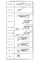
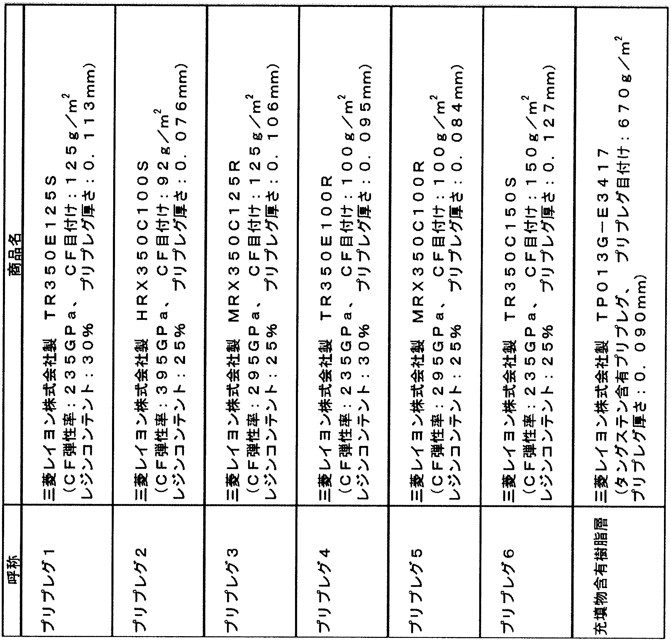
- Table 1 shows the golf club shaft materials produced in the examples and comparative examples.
- tungsten powder (specific gravity 19.3) having an average outer diameter of 3 ⁇ m is uniformly dispersed in the filler-containing resin layer.
- Example 1 ⁇ Mandrel> A mandrel H having the shape shown in FIG. 2 was prepared.
- the mandrel H is made of an iron cylinder and has an outer diameter, a length, and a taper degree as follows.
- P1 outer diameter 5.10 mm
- P2 outer diameter 6.10 mm
- P3 outer diameter 8.00 mm
- P4 and P5 outer diameter 13.40 mm
- P1 to P2 distance (l1) 200 mm
- P2 -P3 distance (l2) 120 mm
- P1-P4 distance (l3) 975 mm
- P1-P5 distance (l4) 1500 mm
- P1-P2 taper degree 5.00 / 1000
- P3-P4 taper Degree 8.24 / 1000.
- ⁇ Cutting and winding of prepreg> The position where the prepreg is wound around the mandrel H is a portion from 70 mm to 1260 mm as measured from the narrow end side.
- prepregs (patterns 1 to 8) cut into the shape shown in FIG. 3 were sequentially wound around the mandrel H, and a polypropylene shrink tape having a width of 20 mm was wound on the prepreg at a pitch of 2 mm.
- the length of each part of each pattern in FIG. 3 is as follows.
- the prepreg 1 shown in Table 1 was used, and the carbon fiber was placed at the head end portion at 0 ° with respect
- a prepreg 2 shown in Table 1 was used as a bias layer.
- Two prepregs 2 having carbon fibers oriented at + 45 ° with respect to the axial direction of the mandrel and prepregs 2 oriented at ⁇ 45 ° are superposed.
- the pattern 2 is overlapped so that the two winding start end portions (upper end in the prepreg diagram) are shifted by 10 mm at the end portion on the left side (small diameter side) of the pattern 2 in FIG. On the large diameter side), the two winding start ends are overlapped so as to be displaced by 22 mm.
- the prepreg 3 shown in Table 1 was wound in the same manner as pattern 1 to form a tip reinforcing layer.
- the filler-containing resin layer W containing tungsten shown in Table 1 and the fiber reinforced resin layer X composed of the prepreg 4 shown in Table 1 are arranged adjacent to each other on the large diameter side.
- the carbon fiber was 0 ° with respect to the axial direction of the mandrel.
- it was wound so as not to overlap.
- prepregs shown in Table 1 were used and arranged over the entire length of the shaft, and the carbon fiber was 0 ° with respect to the axial direction of the mandrel to form a straight layer.
- the prepreg 1 shown in Table 1 was used, arranged at the head side tip, and the carbon fiber was 0 ° with respect to the axial direction of the mandrel to form a tip part reinforcing layer.
- the prepreg wound body obtained above was placed in a curing furnace and heated at 145 ° C. for 2 hours to cure the resin of the prepreg, and then the polypropylene tape and mandrel H were removed.
- Both ends of the obtained golf club shaft base tube were cut by 10 mm to a total length of 1170 mm.
- the cantilever flex of the shaft before polishing (the amount of deflection of the shaft small diameter end when a position of 920 mm from the small diameter end is fixed and a weight of 3 kg is hung on the position of 10 mm from the small diameter end of the shaft) was 140 mm. It was. Further, the outer diameter of the small diameter end of the golf club shaft base tube before polishing was 8.75 mm, and the outer diameter of the large diameter end was 15.40 mm.
- the surface of the golf club shaft tube is polished with a cylindrical grinder so that the total length is 1168 mm, the outer diameter of the head side end is 8.50 mm, the outer diameter of the grip side end is 15.45 mm, and the cantilever flex is 150 mm. Finishing was performed to obtain a golf club shaft.
- the weight of the golf club shaft of Example 1 is 61.5 g, Lg / Ls is 0.553, and the torsion angle of the shaft (fixed at a position of 1035 mm from the shaft small diameter end, from the shaft head side end to the shaft head side end)
- the angle at which the shaft twisted when a torque of 138.5 kgf ⁇ mm was applied to the 50 mm position was 3.7 degrees.
- the obtained shaft was a length of 150 mm, a weight per unit area of 670 g / m 2 , and 4.4% of the total mass of the shaft, in which tungsten powder was uniformly dispersed as a filler at a position of 140 to 290 mm from the grip side end.
- Example 2 A prepreg (patterns 1 to 8) cut into the shape shown in FIG. 4 was sequentially wound around the mandrel H, and a golf club shaft was obtained in the same manner as in Example 1.
- part of each pattern in FIG. 4 is as follows, and the space
- Example 5 (Example 5)
- Table 2 shows the characteristics of this golf club shaft.
- Example 6 (Example 6)
- Table 2 shows the characteristics of this golf club shaft.
- Example 2 A golf club shaft was obtained in the same manner as in Example 2 except that the filler-containing resin layer W of Pattern 4 was not used. Table 2 shows the evaluation results of the obtained golf club shaft.
- Example 3 A golf club shaft was obtained in the same manner as in Example 2 except that the interval from the grip side end of the filling-containing resin layer W of Pattern 4 was changed to 430 mm. Table 2 shows the evaluation results of the obtained golf club shaft.
- Example 4 Example 2 except that instead of the filler-containing resin layer W of the pattern 4, a glass fiber-containing prepreg (manufactured by Mitsubishi Rayon Co., Ltd., GE352G135S, prepreg basis weight 200 g / m 2 , prepreg thickness 0.110 mm) was used. Similarly, a golf club shaft was obtained. Table 2 shows the evaluation results of the obtained golf club shaft.
- a glass fiber-containing prepreg manufactured by Mitsubishi Rayon Co., Ltd., GE352G135S, prepreg basis weight 200 g / m 2 , prepreg thickness 0.110 mm
- ⁇ Ballistic measurement evaluation> A tester (human) tried the golf clubs of Examples 1 to 4 and Comparative Examples 1 to 4 and measured the trajectory. Using the following TrackMan's ballistic measuring device “TrackMan Pro2”, 5 balls of each club were tried. The average value from the data of 5 balls was taken as the ballistic measurement result.
- the trajectory is measured by using a trackman “TrackMan Pro2” manufactured by TrackMan. Table 5 shows the measurement results. The contents of the evaluation items in Table 5 are shown below.
- Club Speed is the speed to impact.
- Ball Speed is the speed of the ball after impact.
- Vertical Angle is the horizontal launch angle (up and down launch angle) immediately after impact.
- Horizontal Angle is the launch angle from the target line immediately after impact (left and right launch angles) + is rightward and-is leftward.
- Spin Rate is the number of rotations of the ball immediately after impact.
- Spin Axis is the spin axis of the ball. + Is slice rotation,-is hook rotation.
- the vertical flight distance is the total flight distance.
- the horizontal flight distance is the difference in the horizontal direction from the target line. + Is right direction,-is left direction.
- the result of Table 5 will be obtained.
- the golf club shaft of the present invention By using the golf club shaft of the present invention, it is possible to maintain ease of swinging even when a high-weight head is attached, and even when the target golfer is a professional golfer or a general expert, a favorable feeling can be obtained. The flight distance of the hit ball can be increased.
- Mandrel 21 Prepreg (Reinforcement layer at the tip) 22 Prepreg (Bias layer) 23a Filling-containing resin layer 23b Fiber reinforced resin layer 23c Filling-containing resin layer (another shape 1) 23d Fiber reinforced resin layer (different shape 1) 23e Filling-containing resin layer (different shape 2) 23f Fiber reinforced resin layer (different shape 2) 24 prepreg (first straight layer) 25 prepreg (second straight layer) 26 Prepreg (third straight layer) 27 Prepreg (tip outer diameter adjustment layer)
Landscapes
- Health & Medical Sciences (AREA)
- General Health & Medical Sciences (AREA)
- Physical Education & Sports Medicine (AREA)
- Golf Clubs (AREA)
Abstract
Description
本願は、2014年1月8日に、日本に出願された特願2014-1896号に基づき優先権を主張し、その内容をここに援用する。
上述のように、打球の飛距離増大の達成のためには、ボールの初速の増加が必要であるが、その手段として、ヘッド重量を大きくすることが考えられる。しかし、単にヘッド重量を大きくすると、ゴルフクラブの慣性モーメントが増大し、スイング時に重さを感じるために、ゴルフクラブの振り易さが低下する。
そこで、この問題点を解消するために、いわゆるハイバランスシャフトと呼ばれる、重心を手元側に寄せたシャフトが提案されている。
これは、シャフトとしての重心を手元側に近づけることにより、ヘッド重量を増加させた場合でも、スイング時に感じる重さを軽減させるものである。特許文献2には、シャフト全長をLs、シャフトのチップ端からシャフト重心Gまでの距離をLgとした時の比(Lg/Ls)が0.52以上0.65以下ある、ハイバランス化されたシャフトが提案されている。
しかし、特許文献2におけるハイバランス化は、シャフトのグリップ側の肉厚化によるものと推定され、この場合、シャフトのグリップ側の曲げ剛性の増加も伴うため、シャフト設計に制約が生じ、スイングのフィーリングの最適化が難しいことがあった。また、この肉厚化はシャフトの重量増も伴うため、シャフト全体の重量増を避けるためには、ヘッド側の薄肉化が必要であるが、これがシャフトの強度低下の原因となることがあった。
(1) 複数の繊維強化樹脂層で構成されるゴルフクラブ用シャフトであって、前記ゴルフクラブ用シャフトのグリップ側(太径)端から0~400mmの範囲内に、比重7以上の重物質を含有し、前記ゴルフクラブ用シャフトの全長をLs、ヘッド側(細径)端から前記ゴルフクラブ用シャフトの重心までの距離をLgとした際に、Lg/Lsが0.54~0.65の範囲である、ゴルフクラブ用シャフト。
(2) 複数の繊維強化樹脂層で構成されるゴルフクラブ用シャフトであって、前記重物質を充填物として含有する長さ20~400mmの充填物含有樹脂層Wを有する、上記(1)に記載のゴルフクラブ用シャフト。
(3) 複数の繊維強化樹脂層で構成されるゴルフクラブ用シャフトであって、前記充填物含有樹脂層Wの目付が500g/m2以上である、上記(2)に記載のゴルフクラブ用シャフト。
(4) 複数の繊維強化樹脂層で構成されるゴルフクラブ用シャフトであって、グリップ側端部の外径が14.5mm~15.7mmの範囲である、上記(1)~(3)のいずれかに記載のゴルフクラブ用シャフト。
(5) 前記ゴルフクラブ用シャフトの総質量に対して、前記充填物含有樹脂層Wを10質量%未満の範囲で有する、上記(2)~(4)のいずれかに記載のゴルフクラブ用シャフト。
(6) 前記ゴルフクラブ用シャフトの総質量に対して、前記充填物含有樹脂層Wを4質量%以上の範囲で有する、上記(2)~(5)のいずれかに記載のゴルフクラブ用シャフト。
(7) 前記充填物含有樹脂層Wよりもグリップ端(太径端)側に、前記充填物含有樹脂層Wと隣接して、前記充填物含有樹脂層Wとの厚みの差が-70μm~+110μmである繊維強化樹脂層Xを有する、上記(2)~(6)のいずれかに記載のゴルフクラブ用シャフト。
(9) 下記式で表されるキックポイントが45.0%未満である、上記(1)~(8)のいずれかに記載のゴルフクラブ用シャフト。
キックポイント(%)=(LK/LB)×100
LK:シャフトの両端に、該両端の直線距離がシャフト長の98.5~99.5%となるように圧縮荷重をかけることで湾曲させた際の、該両端同士を結ぶ直線に、前記湾曲の頂点から垂線を引いた際の交点とシャフトのチップ端部との距離
LB:シャフトの両端に該両端の直線距離がシャフト長の98.5~99.5%となるように圧縮荷重をかけることで湾曲させた際のシャフトの両端同士の直線距離
(10) 前記キックポイントが44.0%未満である、上記(9)に記載のゴルフクラブ用シャフト。
(11) 複数の繊維強化樹脂層で構成されるゴルフクラブ用シャフトを備えるゴルフクラブであって、前記ゴルフクラブ用シャフトは、グリップ側端から0~400mmの範囲内に、比重7以上の重物質を含有し、ゴルフクラブ用シャフトの全長をLs、ヘッド側端から前記ゴルフクラブ用シャフトの重心までの距離をLgとした際に、Lg/Lsが0.54~0.65の範囲であるゴルフクラブ用シャフトを装着したゴルフクラブ。
(12) 前記充填物含有樹脂層Wが、長さ20~355mmであり、かつ前記ゴルフクラブ用シャフトのグリップ側端から0~355mmの範囲内に存在する、上記(11)に記載のゴルフクラブ。
本実施形態のゴルフクラブ用シャフトにおいては、比重7以上の物質である重物質を含有させる必要がある。これによって、ゴルフクラブ用シャフト総重量を過度に増加させることなく、また、しなり(曲げ剛性)や強度の設計に制約を与えることなく、ゴルフクラブ用シャフトの重心位置をコントロールすることが可能となる。一方、比重が7未満の物質を用いた場合でも、これを大量に使用すれば、重心位置をコントロールすることは可能である。しかし、これはシャフトの曲げ剛性の局所的な増大や無用な太径化の原因となり、シャフト設計の障害となる傾向にある。重物質の好ましい比重は10以上であり、さらに好ましくは15以上である。
なお、ここで定義される比重は、対象物質の4℃における密度と4℃における水の密度との比である。
本実施形態のゴルフクラブ用シャフトに使用することのできる比重7以上の重物質としては、特に限定されるものではなく、例えば、クロム(比重7)、亜鉛(比重7.1)、マンガン(比重7.2)、鉄(比重7.9)、コバルト(比重8.9)、ニッケル(比重8.9)、銅(比重8.9)、ビスマス(比重9.8)、モリブデン(比重10.2)、銀(比重10.5)、鉛(比重11.3)、水銀(比重13.6)、タングステン(比重19.3)、金(比重19.3)、若しくは白金(比重21.4)等の金属やこれらを含有する合金類、ゴム、又は樹脂等を挙げることができる。
これらは、単独又は二種類以上を適宜選択して使用することができるが、価格や人体への影響や法規制などの観点から鉄、タングステンが好ましく、特に好ましくはタングステンである。
また、これら重物質の形状は、特に限定されるものではなく、粒子状、粉末状、針状、繊維状、織物状、板状、又は液状等から適宜選択することができるが、シャフトを構成する樹脂への分散性を均一にでき、シャフトへの優れた強度や耐久性の付与も期待できることから、平均外径が0.4μm~10μmの粒子状であるのが好ましく、平均外径が2μm~4μmの粉末状であるのがより好ましい。
さらに、この重物質の少なくとも一部、好ましくは全部は、シャフトのグリップ側端から0~400mmの範囲内に存在させる必要がある。
これは、重物質の位置がシャフトのグリップ側端から離れすぎるとゴルフシャフトの重心を十分にグリップ側端に位置させることができなくなり、本実施形態の目的の達成が困難となるためである。好ましくはシャフトのグリップ側端から360mm以下の範囲内であり、より好ましくは320mm以下の範囲内である。
また、比重7以上の重物質の位置は、グリップ側端から少し離した方が、ゴルファーがスイングする際に安定したスイングが得られ良好なフィーリングが得られる傾向にある。つまりゴルファーが把持した時に右打ちであれば、重物質が右手近傍に位置しているのが好ましい。
従って、重物質は、シャフトのグリップ側端から50mm以上の範囲内に位置するのが好ましい。より好ましくは70mm以上の範囲内である。
本実施形態においては、ゴルフクラブ用シャフトの全長をLs、ヘッド側端からゴルフクラブ用シャフトの重心までの距離をLgとした際に、Lg/Lsを0.54~0.65の範囲とする必要がある。これは、Lg/Lsが0.54未満だと、ヘッドを高重量化した時にこれをより重く感じるために、クラブを振り難くなるためである。好ましくは0.55以上であり、より好ましくは0.56以上である。また、Lg/Lsが0.65を超えると、ヘッド重量を過度に大きくしなければ従来と同程度のスイングバランスが確保できずクラブ総重量が増してしまい、やはりクラブを振り難くなるためである。好ましくは0.61以下であり、より好ましくは0.60以下である。
充填物含有樹脂層Wは、上述の重物質を充填物として含有するものであり、グリップ側端から0~400mmの範囲の部位に存在させることによって、ゴルフクラブ用シャフトの重心を十分にグリップ側端に位置させることができるものであり、本実施形態の目的達成のために好適に利用できるものである。
この充填物含有樹脂層Wの長さは、20~400mmの範囲であるのが好ましい。これは、充填物含有樹脂層Wの長さを20mm以上とすることによって、ゴルフクラブ用シャフトの重心を十分にグリップ端側に位置させることができる傾向にあるためである。より好ましくは50mm以上、特に好ましくは100mm以上である。また、充填物含有樹脂層Wの長さを400mm以下とすることによって、シャフトの質量が重くなり過ぎないようにできる傾向にあるためである。より好ましくは355mm以下であり、さらに好ましくは300mm以下であり、特に好ましくは200mm以下である。なお、充填物含有樹脂層Wの長さとは、シャフトに巻く際の長手方向の最大長をいう。
また、充填物含有樹脂層Wの目付は、500g/m2以上であることが好ましい。これは、この目付を500g/m2以上とすることによって、ゴルフクラブ用シャフトの重心を充分にグリップ端側に位置させることができる傾向にあるためである。より好ましくは、550g/m2以上であり、さらに好ましくは600g/m2以上である。
さらに、充填物含有樹脂層Wの目付は、900g/m2以下とするのが好ましい。これは、この目付を900g/m2以下とすることによって、シャフトの高重量化やシャフトの外径の増大を回避できる傾向にあるためである。より好ましくは800g/m2以下であり、さらに好ましくは750g/m2以下である。
本実施形態のゴルフクラブ用シャフトのグリップ側端部の外径は14.5mm~15.7mmの範囲とするのが好ましい。ここでグリップ側端部の外径とは、グリップ側端部周辺の外見で最も大きい径を指す。これは、グリップ側端部の外径を14.5mm以上とすることによって、対象ゴルファーがプロゴルファーや一般上級者である場合であっても、十分な曲げ剛性が得られ且つ握りやすいクラブが得られる傾向にあるためである。より好ましくは14.8mm以上であり、さらに好ましくは15.0mm以上である。また、これは、グリップ側太径端部の外径を15.7mm以下とすることによって、握りやすいクラブが得られる傾向にあるためである。より好ましくは15.6mm以下であり、さらに好ましくは15.5mm以下である。
本実施形態においては、ゴルファーが把持する範囲で外径差や剛性差を感じることなく良好なフィーリングを得るという観点から、本実施形態のゴルフクラブ用シャフトは、充填物含有樹脂層Wよりも太径端側に、充填物含有樹脂層Wと隣接して、充填物含有樹脂層Wとの厚みの差が-70μm~+110μmである繊維強化樹脂層Xを有するのが好ましい。
繊維強化樹脂層Xに使用されるマトリックス樹脂としては、特に限定されないが、通常エポキシ樹脂が用いられる。エポキシ樹脂としては、例えばビスフェノールA型エポキシ樹脂、ビスフェノールF型エポキシ樹脂、ビスフェノールS型エポキシ樹脂、フェノールノボラック型エポキシ樹脂、クレゾールノボラック型エポキシ樹脂、グリシジルアミン型エポキシ樹脂、イソシアネート変性エポキシ樹脂、又は脂環式エポキシ樹脂などを使用し得る。これらのエポキシ樹脂は、液状のものから固体状のものまで使用できる。更に、単一種類のエポキシ樹脂又は2種類以上のエポキシ樹脂をブレンドして使用することもできる。又エポキシ樹脂には、硬化剤を配合して用いることが多い。
[充填物含有樹脂層W]
充填物含有樹脂層Wは、長さLa20~400mmである。充填物含有樹脂Wの長さは、好ましくは20mm以上、より好ましくは50mm以上、特に好ましくは100mm以上であり、好ましくは355mm以下、より好ましくは300mm以下、特に好ましくは200mm以下である。充填物含有樹脂Wの形状としては、図1の23aのような台形状や23cや23eのような三角形状が挙げられ、シャフト円周方向の異方性を防ぎ効果的に重心をグリップ側へ寄せるための観点から台形状が好ましい。
本実施形態においては、ゴルファーが把持する範囲であり外径差や剛性差を感じることなく良好なフィーリングを得る観点から、充填物含有樹脂層Wよりもグリップ端側に、充填物含有樹脂層Wと隣接して、充填物含有樹脂層Wとの厚みの差が-70μm~+110μmである繊維強化樹脂層Xを有することが好ましい。繊維強化樹脂層Xの形状としては、図1の23bのような台形状や23dや23fのような三角形状が挙げられる。繊維方向は目的に応じて適宜設定できる。これらは重ならない限り、例えば、製造上不可避な程度の間隔を有して配置されていてもよい。
繊維強化樹脂層Xを形成する繊維の引張弾性率は特に限定をしないが、把持した部分の剛性を制御するため適宜選択する。強化繊維の配向角度も曲げ剛性を向上させる場合には0°、ねじり剛性を向上させる場合は45°、潰し剛性を高める場合は90°など目的に応じて適宜設計する。
本実施形態のゴルフクラブ用シャフトの好ましい実施形態としては、繊維強化樹脂を積層してなるゴルフクラブ用シャフトであって、充填物含有樹脂層Wとそれに隣接する繊維強化樹脂層Xを有し、ゴルフクラブ用シャフトの全長をLs、細径端からゴルフクラブ用シャフトの重心までの距離をLgとした際に、Lg/Lsが0.54~0.65であり、かつ太径端部の外径が14.5mm~15.7mmであるゴルフクラブ用シャフトである。
充填物含有樹脂層Wや繊維強化樹脂層X以外に、本実施形態のゴルフクラブ用シャフトを構成する繊維強化樹脂層としては、例えば、シャフトの長手方向に対して配向角度+45°及び/又は-45°に強化繊維が配向されたバイアス層、シャフトの長手方向に対して配向角度0°に強化繊維が配向されたストレート層、シャフトの長手方向に対して配向角度90°に強化繊維が配向されたフープ層を挙げることができる。
このキックポイントとは、シャフトの最もしなりやすい位置のことであり、シャフトを両端から圧縮したときに、シャフトが湾曲する頂点とヘッド側端部からの距離をシャフト全長との比率で表したものであり、具体的には下記の式から求められる値である。
キックポイント(%)=(LK/LB)×100
LK:シャフトの両端に、該両端の直線距離がシャフト長の98.5~99.5%となるように圧縮荷重をかけることで湾曲させた際の、該両端同士を結ぶ直線に、前記湾曲の頂点から垂線を引いた際の交点とシャフトのヘッド側端部との距離
LB:シャフトの両端に該両端の直線距離がシャフト長の98.5~9 9.5%となるように圧縮荷重をかけることで湾曲させた際のシャフトの両端同士の直線距離
そして、一般的に、このキックポイントの値に応じて、シャフトは以下の3種類に分類することができる。
・ローキックポイント(先調子):44.0%未満
・ミドルキックポイント(中調子):44.0%以上45.0%未満
・ハイキックポイント(元調子):45.0%以上
本実施形態によって、ハイキックポイントだけでなく、ローキックポイントやミドルキックポイントのシャフトも得ることができる。
<マンドレル>
図2に示す形状のマンドレルHを用意した。このマンドレルHは、鉄製の円筒体からなり、外径、長さ、テーパー度は以下のとおりである。P1の外径=5.10mm、P2の外径=6.10mm、P3の外径=8.00mm、P4およびP5の外径=13.40mm、P1~P2の距離(l1)=200mm,P2~P3の距離(l2)=120mm、P1~P4の距離(l3)=975mm、P1~P5の距離(l4)=1500mm、P1~P2のテーパー度=5.00/1000、P3~P4のテーパー度=8.24/1000である。
マンドレルHにおけるプリプレグを巻き付ける位置は、細径端側から測って70mmから1260mmまでの部分とした。次いで、このマンドレルHに図3に示した形状に裁断されたプリプレグ(パターン1~8)を順次巻き付け、その上に20mm幅のポリプロピレン製収縮テープをピッチ2mmで巻き付けた。
図3中の各パターンの各部位の長さは以下のとおりである。
α1=250mm、α2=53mm、α3=130mm、α4=65mm、α5=1190mm、α6=145mm、α7=65mm、α8=300mm、α9=29mm、α10=200mm、α11=22mm、α12=150mm、α13=150mm、α14=46mm、α15=200mm、α16=50mm、α17=1190mm、α18=113mm、α19=45mm、α20=1190mm、α21=57mm、α22=23mm、α23=1190mm、α24=58mm、α25=24mm、α26=130mm、α27=80mm
パターン1は表1記載のプリプレグ1を用い、ヘッド側先端部に配置し炭素繊維がマンドレルの軸方向に対して0°とし先端部分補強層とした。パターン2は表1記載のプリプレグ2を用いバイアス層とした。炭素繊維がマンドレルの軸方向に対して+45°に配向したプリプレグ2と-45°に配向したプリプレグ2を2枚重ね合せたものである。また、パターン2は図3のパターン2の左側(細径側)において、2枚の巻き始め端部(プリプレグ図中上端)が端部にて10mmずれるように重ねられ、図3右側端部(太径側)において、2枚の巻き始め端部が22mmずれるように重ねられている。パターン3は表1記載のプリプレグ3をパターン1同様に巻き付け先端補強層とした。パターン4は表1記載のタングステンを含有した充填物含有樹脂層Wと表1記載のプリプレグ4で構成された繊維強化樹脂層Xを隣接させて太径側に配置し、繊維強化樹脂層Xの炭素繊維をマンドレルの軸方向に対して0°とした。次いで重ならないようにして巻き付けた。パターン5~7は表1記載のプリプレグを用いシャフト全長に配置し、炭素繊維がマンドレルの軸方向に対して0°としてストレート層とした。パターン8は表1記載のプリプレグ1を用い、ヘッド側先端部に配置し、炭素繊維がマンドレルの軸方向に対して0°とし先端部分補強層とした。
上記で得られたプリプレグ巻き付け体を硬化炉に入れ、145℃で2時間加熱してプリプレグの樹脂の硬化処理を行った後、ポリプロピレンテープとマンドレルHとを取り除いた。
得られたシャフトは、グリップ側端から140~290mmの位置に、タングステン粉末が充填物として均一に分散された、長さ150mm、目付670g/m2、シャフトの総質量に対して4.4%の質量を構成する充填物含有樹脂層を有するとともに、このグリップ側端と充填物含有樹脂層Wの間には、充填物含有樹脂層Wとの厚みの差が+5μmである繊維強化樹脂層Xを有していた。
また、得られたシャフトのキックポイントは44.5%であった。
マンドレルHに図4に示した形状に裁断されたプリプレグ(パターン1~8)を順次巻き付け、実施例1と同様にして、ゴルフクラブ用シャフトを得た。
ここで、図4中の各パターンの各部位の長さは以下のとおりであり、パターン4の充填物含有樹脂層Wのグリップ側端からの間隔は150mmである。
α1=250mm、α2=53mm、α3=130mm、α4=65mm、α5=1190mm、α6=145mm、α7=65mm、α8=300mm、α9=29mm、α10=200mm、α11=22mm、α12=150mm、α14=45mm、α16=50mm、α17=1190mm、α18=113mm、α19=45mm、α20=1190mm、α21=57mm、α22=23mm、α23=1190mm、α24=58mm、α25=24mm、α26=130mm、α27=80mm
得られたゴルフクラブ用シャフトの評価結果を表2に示す。
パターン4のα12とα16の長さをそれぞれ、α12=200mm、α16=100mmに変更し、グリップ側端からの間隔を100mmとした以外は、実施例2と同様にして、ゴルフクラブ用シャフトを得た。
得られたゴルフクラブ用シャフトの評価結果を表2に示す。
パターン4のα12とα16の長さをそれぞれ、α12=250mm、α16=150mmに変更し、グリップ側端からの間隔を50mmとした以外は、実施例2と同様にして、ゴルフクラブ用シャフトを得た。
得られたゴルフクラブ用シャフトの評価結果を表2に示す。
実施例2において、パターン3のプリプレグ3の種類をプリプレグ4と同じTR350E100Rに変更し、α8とα10の長さをそれぞれ、α8=180mm、α10=100mmに変更すると、キックポイントが43.5%のゴルフクラブ用シャフトが得られる。
このゴルフクラブ用シャフトの特性を表2に示す。
実施例2において、パターン3のα8とα10の長さをそれぞれ、α8=480mm、α10=380mmに変更すると、キックポイントが45.5%のゴルフクラブ用シャフトが得られる。
このゴルフクラブ用シャフトの特性を表2に示す。
パターン4のα12とα16の長さをそれぞれ、α12=430mm、α16=380mmに変更し、グリップ側端からの間隔を0mmとした以外は、実施例2と同様にして、ゴルフクラブ用シャフトを得た。
得られたゴルフクラブ用シャフトの評価結果を表2に示す。
パターン4の充填物含有樹脂層Wを使用しなかった以外は、実施例2と同様にして、ゴルフクラブ用シャフトを得た。
得られたゴルフクラブ用シャフトの評価結果を表2に示す。
パターン4の充填物含有樹脂層Wのグリップ側端からの間隔を430mmに変更した以外は、実施例2と同様にして、ゴルフクラブ用シャフトを得た。
得られたゴルフクラブ用シャフトの評価結果を表2に示す。
パターン4の充填物含有樹脂層Wの代わりに、ガラス繊維含有プリプレグ(三菱レイヨン株式会社製、GE352G135S、プリプレグ目付200g/m2、プリプレグ厚さ0.110mm)を用いた以外は、実施例2と同様にして、ゴルフクラブ用シャフトを得た。
得られたゴルフクラブ用シャフトの評価結果を表2に示す。

実施例1~4、及び比較例1~4で製造したシャフトのグリップ側端部を切断して全長1100mmとした後、ヘッド側にヘッド(195.7g、440ml、ロフト9.5°)、ソケット(5.7g)、グリップ側に市販のグリップ(50g)を装着し、長さ45.25インチ(1149mm)の試験用のドライバーゴルフクラブを製作した。次いでそれぞれごゴルフクラブにおいて同じスイングバランスが得られるようにそれぞれのゴルフクラブのヘッドソール部分に適量の鉛を貼付した。
得られたゴルフクラブの特性を表3に示す。
また、実施例5と実施例6で得られるシャフトから上記と同様に製作されるドライバーゴルフクラブに表3記載の量の鉛を貼付することで、表3記載のゴルフクラブの特性が得られる。

実施例1~4、及び比較例1~4それぞれのゴルフクラブを上級者ゴルファー3名に5球ずつ試打してもらい感想を聴取した。最も振り易い、最も安心感がある、最も好感があるものを5点として5点満点の評価を行った。全テスターの平均値を表4に示す。
また、実施例5と実施例6から製作されるゴルフクラブに対して、同様な官能評価を行うと、表4記載の結果が得られる。

実施例1~4、及び比較例1~4それぞれのゴルフクラブをテスター(人間)が試打し、弾道を計測した。下記TrackMan社製弾道計測装置「TrackMan Pro2」を用い各クラブ5球ずつ試打した。5球のデータから平均値を弾道計測結果とした。
Club Speedはインパクトまでの速度。
Ball Speedはインパクト後のボールの速度。
Vertical Angleはインパクト直後の水平方向の打ち出し角度(上下の打ち出し角度)。
Horizontal Angleはインパクト直後のターゲットラインからの打ち出し角度(左右の打ち出し角度) +は右方向、-は左方向。
Spin Rateはインパクト直後のボールの回転数。
Spin Axisはボールのスピン軸。+はスライス回転、-はフック回転。
縦方向飛距離はトータル飛距離。
横方向飛距離はターゲットラインからの横方向の差。+は右方向、-は左方向。
また、実施例5と実施例6から製作されるゴルフクラブに対して、同様な弾道計測評価を行うと、表5記載の結果が得られる。

21 プリプレグ(先端補強層)
22 プリプレグ(バイアス層)
23a 充填物含有樹脂層
23b 繊維強化樹脂層
23c 充填物含有樹脂層(別の形状1)
23d 繊維強化樹脂層(別の形状1)
23e 充填物含有樹脂層(別の形状2)
23f 繊維強化樹脂層(別の形状2)
24 プリプレグ(第1のストレート層)
25 プリプレグ(第2のストレート層)
26 プリプレグ(第3のストレート層)
27 プリプレグ(先端外径調整層)
Claims (12)
- 複数の繊維強化樹脂層で構成されるゴルフクラブ用シャフトであって、
前記ゴルフクラブ用シャフトのグリップ側端から0~400mmの範囲内に、比重7以上の重物質を含有し、
前記ゴルフクラブ用シャフトの全長をLs、ヘッド側端から前記ゴルフクラブ用シャフトの重心までの距離をLgとした際に、Lg/Lsが0.54~0.65の範囲である、ゴルフクラブ用シャフト。 - 複数の繊維強化樹脂層で構成されるゴルフクラブ用シャフトであって、前記重物質を充填物として含有する長さ20~400mmの充填物含有樹脂層Wを有する、請求項1記載のゴルフクラブ用シャフト。
- 複数の繊維強化樹脂層で構成されるゴルフクラブ用シャフトであって、前記充填物含有樹脂層Wの目付が500g/m2以上である、請求項2記載のゴルフクラブ用シャフト。
- 複数の繊維強化樹脂層で構成されるゴルフクラブ用シャフトであって、グリップ側端部の外径が14.5mm~15.7mmの範囲である、請求項1~3にいずれかに記載のゴルフクラブ用シャフト。
- 前記ゴルフクラブ用シャフトの総質量に対して、前記充填物含有樹脂層Wを10質量%未満の範囲で有する、請求項2~4のいずれかに記載のゴルフクラブ用シャフト。
- 前記ゴルフクラブ用シャフトの総質量に対して、前記充填物含有樹脂層Wを4質量%以上の範囲で有する、請求項2~5のいずれかに記載のゴルフクラブ用シャフト。
- 前記充填物含有樹脂層Wよりもグリップ端側に、前記充填物含有樹脂層Wと隣接して、前記充填物含有樹脂層Wとの厚みの差が-70μm~+110μmである繊維強化樹脂層Xを有する、請求項2~6のいずれかに記載のゴルフクラブ用シャフト。
- 前記重物質がタングステンである、請求項1~7のいずれかに記載のゴルフクラブ用シャフト。
- 下記式で表されるキックポイントが45.0%未満である、請求項1~8のいずれかに記載のゴルフクラブ用シャフト。
キックポイント(%)=(LK/LB)×100
LK:シャフトの両端に、該両端の直線距離がシャフト長の98.5~99.5%となるように圧縮荷重をかけることで湾曲させた際の、該両端同士を結ぶ直線に、前記湾曲の頂点から垂線を引いた際の交点とシャフトのチップ端部との距離
LB:シャフトの両端に該両端の直線距離がシャフト長の98.5~99.5%となるように圧縮荷重をかけることで湾曲させた際のシャフトの両端同士の直線距離 - 前記キックポイントが44.0%未満である、請求項9に記載のゴルフクラブ用シャフト。
- 複数の繊維強化樹脂層で構成されるゴルフクラブ用シャフトを備えるゴルフクラブであって、前記ゴルフクラブ用シャフトは、グリップ側端から0~400mmの範囲内に、比重7以上の重物質を含有し、前記ゴルフクラブ用シャフトの全長をLs、ヘッド側端から前記ゴルフクラブ用シャフトの重心までの距離をLgとした際に、Lg/Lsが0.54~0.65の範囲である前記ゴルフクラブ用シャフトを装着したゴルフクラブ。
- 前記充填物含有樹脂層Wが、長さ20~355mmであり、かつ前記ゴルフクラブ用シャフトのグリップ側端から0~355mmの範囲内に存在する、請求項11に記載のゴルフクラブ。
Priority Applications (4)
| Application Number | Priority Date | Filing Date | Title |
|---|---|---|---|
| US15/109,333 US20160325157A1 (en) | 2014-01-08 | 2014-12-26 | Golf club shaft and golf club |
| EP14877728.7A EP3093049A4 (en) | 2014-01-08 | 2014-12-26 | GOLFERCHLÄGERSCHAFT AND GOLFSCHLÄGER |
| CN201480072091.8A CN105873647A (zh) | 2014-01-08 | 2014-12-26 | 高尔夫球杆杆身和高尔夫球杆 |
| JP2015503392A JPWO2015105021A1 (ja) | 2014-01-08 | 2014-12-26 | ゴルフクラブ用シャフト及びゴルフクラブ |
Applications Claiming Priority (2)
| Application Number | Priority Date | Filing Date | Title |
|---|---|---|---|
| JP2014-001896 | 2014-01-08 | ||
| JP2014001896 | 2014-01-08 |
Publications (1)
| Publication Number | Publication Date |
|---|---|
| WO2015105021A1 true WO2015105021A1 (ja) | 2015-07-16 |
Family
ID=53523855
Family Applications (1)
| Application Number | Title | Priority Date | Filing Date |
|---|---|---|---|
| PCT/JP2014/084475 WO2015105021A1 (ja) | 2014-01-08 | 2014-12-26 | ゴルフクラブ用シャフト及びゴルフクラブ |
Country Status (5)
| Country | Link |
|---|---|
| US (1) | US20160325157A1 (ja) |
| EP (1) | EP3093049A4 (ja) |
| JP (1) | JPWO2015105021A1 (ja) |
| CN (1) | CN105873647A (ja) |
| WO (1) | WO2015105021A1 (ja) |
Cited By (1)
| Publication number | Priority date | Publication date | Assignee | Title |
|---|---|---|---|---|
| JP2019150392A (ja) * | 2018-03-05 | 2019-09-12 | 三菱ケミカル株式会社 | ゴルフクラブ用シャフト |
Families Citing this family (4)
| Publication number | Priority date | Publication date | Assignee | Title |
|---|---|---|---|---|
| KR102582630B1 (ko) * | 2016-10-28 | 2023-09-22 | 카스턴 매뉴팩츄어링 코오포레이숀 | 항력을 감소시키도록 직경 프로파일이 설정된 골프 클럽 샤프트 |
| US10213666B1 (en) * | 2018-01-31 | 2019-02-26 | Breakthrough Golf Technology Llc | Golf shaft |
| JP6853210B2 (ja) * | 2018-03-01 | 2021-03-31 | グローブライド株式会社 | ゴルフクラブセット |
| WO2020176800A1 (en) * | 2019-02-28 | 2020-09-03 | Lamkin Corporation | Composition and manufacturing methods for grips |
Citations (10)
| Publication number | Priority date | Publication date | Assignee | Title |
|---|---|---|---|---|
| JPH0629559U (ja) * | 1992-09-30 | 1994-04-19 | 横浜ゴム株式会社 | ゴルフクラブ用シャフト |
| JPH06344519A (ja) * | 1993-06-07 | 1994-12-20 | Mitsubishi Rayon Co Ltd | 樹脂成形材料 |
| JPH07116289A (ja) * | 1993-10-20 | 1995-05-09 | Hitachi Chem Co Ltd | 繊維強化樹脂製ゴルフシャフト及びその製造法 |
| JPH09206413A (ja) * | 1996-01-31 | 1997-08-12 | Daiwa Seiko Inc | ゴルフクラブシャフト |
| JPH10155952A (ja) * | 1996-11-29 | 1998-06-16 | Daiwa Seiko Inc | ゴルフクラブシャフト |
| JP2001346925A (ja) * | 2001-04-20 | 2001-12-18 | Daiwa Seiko Inc | ゴルフクラブ用シャフト |
| JP2009189554A (ja) | 2008-02-14 | 2009-08-27 | Mrc Composite Products Co Ltd | ゴルフクラブ用シャフト |
| JP2012147982A (ja) * | 2011-01-20 | 2012-08-09 | Mitsubishi Rayon Co Ltd | ゴルフクラブ用シャフト |
| JP2012239574A (ja) | 2011-05-18 | 2012-12-10 | Dunlop Sports Co Ltd | ゴルフクラブシャフト |
| JP2013138703A (ja) * | 2011-12-28 | 2013-07-18 | Dunlop Sports Co Ltd | ゴルフクラブシャフト及びゴルフクラブ |
Family Cites Families (30)
| Publication number | Priority date | Publication date | Assignee | Title |
|---|---|---|---|---|
| US5434121A (en) * | 1993-03-25 | 1995-07-18 | Mitsui Toatsu Chemicals, Incorporated | Variety of Drechslera monoceras, weed control compositions containing the same as an effective ingredient and weed control methods using the same |
| JPH07124277A (ja) * | 1993-11-05 | 1995-05-16 | Tonen Corp | ゴルフクラブシャフト |
| CN1102858C (zh) * | 1996-11-28 | 2003-03-12 | 韦弗克斯公司 | 具有波浪形加强部的高尔夫球棒杆及其制造方法 |
| JPH10225541A (ja) * | 1997-02-17 | 1998-08-25 | Mitsubishi Rayon Co Ltd | ゴルフクラブ用シャフト |
| US6126557A (en) * | 1997-08-26 | 2000-10-03 | Callaway Golf Company | Golf club shafts and methods of manufacturing the same |
| JP4659058B2 (ja) * | 1997-11-26 | 2011-03-30 | 三菱レイヨン株式会社 | ゴルフクラブ用シャフトの製造方法 |
| JP4142181B2 (ja) * | 1997-11-26 | 2008-08-27 | 三菱レイヨン株式会社 | ゴルフクラブ用シャフト |
| JPH11319170A (ja) * | 1998-03-20 | 1999-11-24 | Fujikura Rubber Ltd | ゴルフクラブ用シャフトおよびゴルフクラブ |
| JP2946331B1 (ja) * | 1998-09-07 | 1999-09-06 | 日本シャフト株式会社 | ゴルフクラブシャフト |
| JP2000225215A (ja) * | 1999-02-08 | 2000-08-15 | Daiwa Seiko Inc | ゴルフクラブ |
| JP2001137404A (ja) * | 1999-11-17 | 2001-05-22 | Honma Golf Co Ltd | ゴルフクラブ用シャフト及びその製造方法 |
| JP4402784B2 (ja) * | 1999-12-10 | 2010-01-20 | 三菱レイヨン株式会社 | ゴルフクラブ用シャフト |
| WO2001047611A1 (en) * | 1999-12-28 | 2001-07-05 | Taylor Made Golf Company, Inc. | Method for localizing weight in a golf club shaft |
| JP2002052103A (ja) * | 2000-08-08 | 2002-02-19 | Sumitomo Rubber Ind Ltd | ゴルフクラブシャフト |
| JP3960375B2 (ja) * | 2002-04-18 | 2007-08-15 | 横浜ゴム株式会社 | シャフトの撓み特性測定装置 |
| JP4330977B2 (ja) * | 2003-10-28 | 2009-09-16 | Sriスポーツ株式会社 | 管状体の製造方法 |
| JP2007125255A (ja) * | 2005-11-04 | 2007-05-24 | Sri Sports Ltd | ゴルフクラブシャフト |
| JP4960687B2 (ja) * | 2005-11-22 | 2012-06-27 | エムアールシーコンポジットプロダクツ株式会社 | ゴルフクラブ用シャフトの特性値の測定方法 |
| JP2009219652A (ja) * | 2008-03-17 | 2009-10-01 | Daiwa Seiko Inc | ゴルフクラブのシャフト |
| JP5457231B2 (ja) * | 2010-03-09 | 2014-04-02 | ダンロップスポーツ株式会社 | ゴルフクラブシャフトの製造方法 |
| JP4880063B1 (ja) * | 2010-11-24 | 2012-02-22 | 藤倉ゴム工業株式会社 | ゴルフクラブシャフト及びその製造方法 |
| JP2012125489A (ja) * | 2010-12-17 | 2012-07-05 | Bridgestone Sports Co Ltd | ゴルフクラブシャフトの選定用器具 |
| JP5186033B1 (ja) * | 2011-10-12 | 2013-04-17 | ダンロップスポーツ株式会社 | ゴルフクラブシャフト及びゴルフクラブ |
| JP5181055B1 (ja) * | 2011-10-12 | 2013-04-10 | ダンロップスポーツ株式会社 | ゴルフクラブシャフト及びゴルフクラブ |
| JP5852837B2 (ja) * | 2011-10-12 | 2016-02-03 | ダンロップスポーツ株式会社 | ゴルフクラブ |
| JP5420626B2 (ja) * | 2011-11-22 | 2014-02-19 | 美津濃株式会社 | アイアンゴルフクラブ |
| US20130137530A1 (en) * | 2011-11-30 | 2013-05-30 | Bridgestone Sports Co., Ltd. | Golf club shaft and golf club |
| JP2013116207A (ja) * | 2011-12-02 | 2013-06-13 | Bridgestone Sports Co Ltd | ゴルフクラブシャフト及びゴルフクラブ |
| CN104582800B (zh) * | 2012-08-31 | 2016-05-11 | 三菱丽阳株式会社 | 高尔夫球杆用杆身 |
| KR20160030291A (ko) * | 2013-07-12 | 2016-03-16 | 카스턴 매뉴팩츄어링 코오포레이숀 | 일관된 클럽 갭핑을 위해 구성된 골프 클럽 및 샤프트 |
-
2014
- 2014-12-26 CN CN201480072091.8A patent/CN105873647A/zh active Pending
- 2014-12-26 JP JP2015503392A patent/JPWO2015105021A1/ja active Pending
- 2014-12-26 EP EP14877728.7A patent/EP3093049A4/en not_active Withdrawn
- 2014-12-26 US US15/109,333 patent/US20160325157A1/en not_active Abandoned
- 2014-12-26 WO PCT/JP2014/084475 patent/WO2015105021A1/ja active Application Filing
Patent Citations (10)
| Publication number | Priority date | Publication date | Assignee | Title |
|---|---|---|---|---|
| JPH0629559U (ja) * | 1992-09-30 | 1994-04-19 | 横浜ゴム株式会社 | ゴルフクラブ用シャフト |
| JPH06344519A (ja) * | 1993-06-07 | 1994-12-20 | Mitsubishi Rayon Co Ltd | 樹脂成形材料 |
| JPH07116289A (ja) * | 1993-10-20 | 1995-05-09 | Hitachi Chem Co Ltd | 繊維強化樹脂製ゴルフシャフト及びその製造法 |
| JPH09206413A (ja) * | 1996-01-31 | 1997-08-12 | Daiwa Seiko Inc | ゴルフクラブシャフト |
| JPH10155952A (ja) * | 1996-11-29 | 1998-06-16 | Daiwa Seiko Inc | ゴルフクラブシャフト |
| JP2001346925A (ja) * | 2001-04-20 | 2001-12-18 | Daiwa Seiko Inc | ゴルフクラブ用シャフト |
| JP2009189554A (ja) | 2008-02-14 | 2009-08-27 | Mrc Composite Products Co Ltd | ゴルフクラブ用シャフト |
| JP2012147982A (ja) * | 2011-01-20 | 2012-08-09 | Mitsubishi Rayon Co Ltd | ゴルフクラブ用シャフト |
| JP2012239574A (ja) | 2011-05-18 | 2012-12-10 | Dunlop Sports Co Ltd | ゴルフクラブシャフト |
| JP2013138703A (ja) * | 2011-12-28 | 2013-07-18 | Dunlop Sports Co Ltd | ゴルフクラブシャフト及びゴルフクラブ |
Non-Patent Citations (1)
| Title |
|---|
| See also references of EP3093049A4 |
Cited By (2)
| Publication number | Priority date | Publication date | Assignee | Title |
|---|---|---|---|---|
| JP2019150392A (ja) * | 2018-03-05 | 2019-09-12 | 三菱ケミカル株式会社 | ゴルフクラブ用シャフト |
| JP7098961B2 (ja) | 2018-03-05 | 2022-07-12 | 三菱ケミカル株式会社 | ゴルフクラブ用シャフト |
Also Published As
| Publication number | Publication date |
|---|---|
| EP3093049A4 (en) | 2016-12-21 |
| US20160325157A1 (en) | 2016-11-10 |
| JPWO2015105021A1 (ja) | 2017-03-23 |
| EP3093049A1 (en) | 2016-11-16 |
| CN105873647A (zh) | 2016-08-17 |
Similar Documents
| Publication | Publication Date | Title |
|---|---|---|
| WO2015105021A1 (ja) | ゴルフクラブ用シャフト及びゴルフクラブ | |
| CN101920094B (zh) | 多段共固化的高尔夫球杆杆身 | |
| US7736245B2 (en) | Golf club shaft and golf club | |
| JP2022078195A (ja) | 抗力を低減させるための直径プロファイルのゴルフクラブシャフト | |
| JP2006102038A (ja) | ゴルフクラブ | |
| US9463362B2 (en) | Golf club and shaft | |
| JP6729075B2 (ja) | ゴルフクラブ | |
| JP6798897B2 (ja) | ゴルフクラブ | |
| JP2003190341A (ja) | ゴルフクラブシャフト | |
| JP2003180890A (ja) | ゴルフクラブシャフト | |
| JP2019150256A (ja) | ゴルフクラブセット | |
| JP5291356B2 (ja) | ゴルフクラブ用シャフト | |
| JP3433793B2 (ja) | アイアンゴルフクラブセット | |
| JP6908538B2 (ja) | ゴルフクラブ | |
| JP6715752B2 (ja) | ゴルフクラブ用シャフト | |
| JP6786801B2 (ja) | ゴルフクラブ用シャフトの製造方法 | |
| JP6213063B2 (ja) | ゴルフクラブ用シャフト | |
| JP2018171391A (ja) | パター用ゴルフシャフト | |
| CN113195063B (zh) | 高尔夫球杆杆身以及高尔夫球杆 | |
| JP6492639B2 (ja) | ゴルフクラブ及びシャフト | |
| JP2018171343A (ja) | パター用ゴルフシャフト | |
| JP2020146139A (ja) | ゴルフクラブ用シャフト | |
| JP2017113207A (ja) | ゴルフクラブ用シャフト及びゴルフクラブ | |
| JP2021159712A (ja) | ゴルフクラブ用シャフト、及び、ゴルフクラブ用シャフトの製造方法 | |
| JP2019150392A (ja) | ゴルフクラブ用シャフト |
Legal Events
| Date | Code | Title | Description |
|---|---|---|---|
| ENP | Entry into the national phase |
Ref document number: 2015503392 Country of ref document: JP Kind code of ref document: A |
|
| 121 | Ep: the epo has been informed by wipo that ep was designated in this application |
Ref document number: 14877728 Country of ref document: EP Kind code of ref document: A1 |
|
| REEP | Request for entry into the european phase |
Ref document number: 2014877728 Country of ref document: EP |
|
| WWE | Wipo information: entry into national phase |
Ref document number: 2014877728 Country of ref document: EP |
|
| WWE | Wipo information: entry into national phase |
Ref document number: 15109333 Country of ref document: US |
|
| NENP | Non-entry into the national phase |
Ref country code: DE |