WO2015076341A1 - 表皮付き製品の製造方法 - Google Patents
表皮付き製品の製造方法 Download PDFInfo
- Publication number
- WO2015076341A1 WO2015076341A1 PCT/JP2014/080792 JP2014080792W WO2015076341A1 WO 2015076341 A1 WO2015076341 A1 WO 2015076341A1 JP 2014080792 W JP2014080792 W JP 2014080792W WO 2015076341 A1 WO2015076341 A1 WO 2015076341A1
- Authority
- WO
- WIPO (PCT)
- Prior art keywords
- skin
- cushion layer
- base material
- stitch line
- back surface
- Prior art date
- Legal status (The legal status is an assumption and is not a legal conclusion. Google has not performed a legal analysis and makes no representation as to the accuracy of the status listed.)
- Ceased
Links
Images


Classifications
-
- B—PERFORMING OPERATIONS; TRANSPORTING
- B32—LAYERED PRODUCTS
- B32B—LAYERED PRODUCTS, i.e. PRODUCTS BUILT-UP OF STRATA OF FLAT OR NON-FLAT, e.g. CELLULAR OR HONEYCOMB, FORM
- B32B37/00—Methods or apparatus for laminating, e.g. by curing or by ultrasonic bonding
- B32B37/14—Methods or apparatus for laminating, e.g. by curing or by ultrasonic bonding characterised by the properties of the layers
- B32B37/16—Methods or apparatus for laminating, e.g. by curing or by ultrasonic bonding characterised by the properties of the layers with all layers existing as coherent layers before laminating
-
- B—PERFORMING OPERATIONS; TRANSPORTING
- B32—LAYERED PRODUCTS
- B32B—LAYERED PRODUCTS, i.e. PRODUCTS BUILT-UP OF STRATA OF FLAT OR NON-FLAT, e.g. CELLULAR OR HONEYCOMB, FORM
- B32B5/00—Layered products characterised by the non- homogeneity or physical structure, i.e. comprising a fibrous, filamentary, particulate or foam layer; Layered products characterised by having a layer differing constitutionally or physically in different parts
- B32B5/22—Layered products characterised by the non- homogeneity or physical structure, i.e. comprising a fibrous, filamentary, particulate or foam layer; Layered products characterised by having a layer differing constitutionally or physically in different parts characterised by the presence of two or more layers which are next to each other and are fibrous, filamentary, formed of particles or foamed
- B32B5/24—Layered products characterised by the non- homogeneity or physical structure, i.e. comprising a fibrous, filamentary, particulate or foam layer; Layered products characterised by having a layer differing constitutionally or physically in different parts characterised by the presence of two or more layers which are next to each other and are fibrous, filamentary, formed of particles or foamed one layer being a fibrous or filamentary layer
-
- B—PERFORMING OPERATIONS; TRANSPORTING
- B32—LAYERED PRODUCTS
- B32B—LAYERED PRODUCTS, i.e. PRODUCTS BUILT-UP OF STRATA OF FLAT OR NON-FLAT, e.g. CELLULAR OR HONEYCOMB, FORM
- B32B7/00—Layered products characterised by the relation between layers; Layered products characterised by the relative orientation of features between layers, or by the relative values of a measurable parameter between layers, i.e. products comprising layers having different physical, chemical or physicochemical properties; Layered products characterised by the interconnection of layers
- B32B7/04—Interconnection of layers
- B32B7/08—Interconnection of layers by mechanical means
- B32B7/09—Interconnection of layers by mechanical means by stitching, needling or sewing
-
- B—PERFORMING OPERATIONS; TRANSPORTING
- B60—VEHICLES IN GENERAL
- B60R—VEHICLES, VEHICLE FITTINGS, OR VEHICLE PARTS, NOT OTHERWISE PROVIDED FOR
- B60R13/00—Elements for body-finishing, identifying, or decorating; Arrangements or adaptations for advertising purposes
- B60R13/02—Internal Trim mouldings ; Internal Ledges; Wall liners for passenger compartments; Roof liners
-
- B—PERFORMING OPERATIONS; TRANSPORTING
- B32—LAYERED PRODUCTS
- B32B—LAYERED PRODUCTS, i.e. PRODUCTS BUILT-UP OF STRATA OF FLAT OR NON-FLAT, e.g. CELLULAR OR HONEYCOMB, FORM
- B32B38/00—Ancillary operations in connection with laminating processes
- B32B2038/0052—Other operations not otherwise provided for
- B32B2038/008—Sewing, stitching
-
- B—PERFORMING OPERATIONS; TRANSPORTING
- B32—LAYERED PRODUCTS
- B32B—LAYERED PRODUCTS, i.e. PRODUCTS BUILT-UP OF STRATA OF FLAT OR NON-FLAT, e.g. CELLULAR OR HONEYCOMB, FORM
- B32B2605/00—Vehicles
-
- B—PERFORMING OPERATIONS; TRANSPORTING
- B32—LAYERED PRODUCTS
- B32B—LAYERED PRODUCTS, i.e. PRODUCTS BUILT-UP OF STRATA OF FLAT OR NON-FLAT, e.g. CELLULAR OR HONEYCOMB, FORM
- B32B2605/00—Vehicles
- B32B2605/003—Interior finishings
-
- B—PERFORMING OPERATIONS; TRANSPORTING
- B32—LAYERED PRODUCTS
- B32B—LAYERED PRODUCTS, i.e. PRODUCTS BUILT-UP OF STRATA OF FLAT OR NON-FLAT, e.g. CELLULAR OR HONEYCOMB, FORM
- B32B37/00—Methods or apparatus for laminating, e.g. by curing or by ultrasonic bonding
- B32B37/12—Methods or apparatus for laminating, e.g. by curing or by ultrasonic bonding characterised by using adhesives
-
- B—PERFORMING OPERATIONS; TRANSPORTING
- B32—LAYERED PRODUCTS
- B32B—LAYERED PRODUCTS, i.e. PRODUCTS BUILT-UP OF STRATA OF FLAT OR NON-FLAT, e.g. CELLULAR OR HONEYCOMB, FORM
- B32B38/00—Ancillary operations in connection with laminating processes
- B32B38/18—Handling of layers or the laminate
- B32B38/1825—Handling of layers or the laminate characterised by the control or constructional features of devices for tensioning, stretching or registration
- B32B38/1833—Positioning, e.g. registration or centering
- B32B38/1841—Positioning, e.g. registration or centering during laying up
Definitions
- the present invention relates to a method of manufacturing a product with a skin in which a stitch line is formed on a part of the surface of the skin.
- a base material As interior parts such as automotive instrument panels and consoles, a base material, a laminated material that is provided on the base material and is formed by laminating a cushion layer on the back side of the skin, and a line along the surface of the skin And a stitch line composed of a plurality of stitches arranged in a shape (hereinafter referred to as a product with a skin) are known.
- a product with a skin a stitch line composed of a plurality of stitches arranged in a shape
- a stitch line forming portion 55 is provided in a laminated material 51 as shown in FIG.
- each surface of the skin 52 and the cushion layer 53 is recessed toward the base material 56, and each back surface protrudes toward the base material 56.
- the stitch line 54 is formed on the surface of the skin 52 by stitching the cushion layer 53 and the skin 52 together in the stitch line forming portion 55.
- the base material 56 is provided with a stitch line corresponding portion 57.
- compatible part 57 the surface of the base material 56 is dented toward the back surface.
- the laminated material 51 is fixed to the base material 56 by the stitch line forming portion 55 being bonded to the stitch line corresponding portion 57.
- the present invention has been made in view of such circumstances, and the object thereof is to provide a product with a skin that has a hollow portion in a part of the skin and a stitch line at the bottom of the hollow portion.
- An object of the present invention is to provide a method for manufacturing a product with a skin that can be manufactured without performing an alignment operation.
- a method of manufacturing a product with a skin that solves the above problems is provided with a skin having a front surface and a back surface, a base material having a front surface and a back surface, a surface of the base material, and a back surface of the skin from the same skin.
- a method of manufacturing a product with a skin comprising a laminated material constituted by laminating a soft cushion layer and a stitch line constituted by a plurality of seams arranged linearly along the surface of the skin Forming the stitch line on the surface of the skin by stitching the cushion layer and the skin so that a part of the cushion layer in the laminate is recessed toward the skin; And at least the process of affixing in the state which contact
- the cushion layer and the skin in the laminated material are stitched together. Since the cushion layer in the laminated material is softer than the skin, when the cushion layer and the skin are stitched together, a part of the cushion layer is pulled toward the skin by the thread. Therefore, the peripheral part of the same thread on the back surface of the cushion layer is recessed toward the skin.
- a stitch line composed of a plurality of seams arranged linearly along the surface is formed on the surface of the epidermis.
- the affixing process it is affixed in a state where the back surface of the laminated material and the substantially entire surface including the back surface of the stitched portion are in close contact with the base material.
- the cushion layer before the attaching process, the portion that was pulled and depressed toward the outer skin by sewing is pulled back toward the substrate, and the surface of the substrate is not similar to the portion that is not stitched and not depressed. It is made into the shape along, and is affixed on the same base material. In this pasting, it is not necessary to strictly align the laminate with the substrate.
- a shape obtained by inverting the shape before the pasting process is formed on a part of the laminated material. That is, a hollow portion having a stitch line at the bottom while being depressed toward a base material in a part of the skin.
- the laminated material a material in which a three-dimensional cushion layer is laminated on the skin is suitable.
- the three-dimensional knitted cushion layer has excellent compression characteristics (high rigidity) compared to other types of cushion layers. Therefore, when the three-dimensional knitted cushion layer and the skin are stitched together in the stitch line forming step, only the portion close to the stitch line in the three-dimensional knitted cushion layer is pulled toward the skin.
- a clear recess is formed only in a portion close to the stitch line.
- a pressing force is applied to at least one of the base material and the laminated material in a direction to approach each other, and the laminated material is pasted on the base material. It is preferable that the pressing force is released.
- a force is applied to press at least one of the base material and the laminated material in a direction in which they are brought close to each other.
- This force acts against the elastic restoring force of the cushion layer, and the cushion layer is compressed toward the substrate. Therefore, it is affixed suitably in the state which is the back surface of a laminated material and substantially the whole surface including the back surface of the part stitched together closely_contact
- the portion of the cushion layer that was pulled and depressed toward the outer skin by sewing before the attaching process is pulled back toward the substrate, and the portion of the substrate that is not sewn and not recessed is similar to the cushion layer. It becomes a shape along the surface and is affixed to the same substrate.
- the pressing force is released after the laminated material is attached to the substrate. Then, the force for compressing the cushion layer is lost, and the cushion layer tries to return to the original state by its own elastic restoring force.
- the restoration by the elastic restoring force is limited by the thread. Therefore, the shape which reversed the shape before a sticking process is formed in a part of laminated material. That is, a hollow portion having a stitch line at the bottom while being depressed toward a base material in a part of the skin.
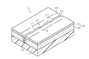
- FIG. 2 is a partial perspective view of a product with an outer skin manufactured by the manufacturing method of FIGS. 1 (a) to 1 (e).
- the fragmentary sectional view which shows the 1st modification of a product with a skin.
- the fragmentary sectional view which shows the 2nd modification of a product with a skin.
- the fragmentary sectional view which shows the 3rd modification of a product with a skin.
- FIG. 10 is a partial cross-sectional view showing a state in the middle of manufacturing the skin-covered products of the first to third modifications, and showing a state in which a pair of laminated materials are stitched together.
- the fragmentary sectional view which shows the state in the middle of manufacturing the product with the conventional skin.
- FIGS. 1 and 2 First, an embodiment of a method for manufacturing a product with a skin will be described with reference to FIGS. 1 and 2.
- a product with a skin manufactured by the manufacturing method of the present embodiment will be described.
- various automotive interior products such as automotive instrument panels, consoles, door trims, glove boxes, pillar garnishes, etc. are targeted for products with skins.
- a product with a skin is illustrated in a simple shape.
- the product with skin 10 includes a base material 11, a laminated material 12, and a stitch line 17 as main constituent members. Next, each component of the product with skin 10 will be described.
- the base material 11 is a member that forms the skeleton of the product 10 with skin, and ensures the rigidity of the product 10 with skin.
- the base material 11 is formed into a product shape by resin molding such as injection molding using a resin material such as polypropylene or polyethylene.
- the base material 11 may have a non-flat surface such as a curved surface, a bent surface, and an uneven surface.
- the laminated material 12 is a member corresponding to the surface layer portion of the product 10 with skin.
- the laminated material 12 is disposed on the substrate 11 by the laminated material 12 being attached to the substrate 11 with the back surface of the laminated material 12 being in close contact with the surface of the substrate 11.
- the laminated material 12 is composed of a skin 13 that constitutes the design surface of the product 10 with skin, and a cushion layer 14 that is laminated on the back surface (lower side in FIG. 2) of the skin 13 and is softer than the skin 13.
- the skin 13 is mainly used for the purpose of improving the texture and touch of the product 10 with the skin.
- the skin 13 is formed into a sheet having a uniform thickness by synthetic leather made of vinyl chloride, thermoplastic elastomer (TPE), or the like, and can be deformed in the thickness direction or the like.
- the thickness of the skin 13 is preferably 0.35 to 1.5 mm. If the thickness of the skin 13 is smaller than 0.35 mm, wrinkles may occur in a portion near the stitch line 17 in the skin 13 in the process of manufacturing the product 10 with the skin. On the other hand, when the thickness of the skin 13 is larger than 1.5 mm, the skin 13 becomes hard. When the skin 13 is hard, when the laminated material 12 is affixed to the base material 11, the skin 13 is hard to deform
- the cushion layer 14 is constituted by a three-dimensional knitted cushion layer and has elasticity.
- the cushion layer 14 is used to improve the tactile sensation of the product 10 with the skin.
- the cushion layer 14 is formed using a double raschel knitting machine and is connected between a pair of ground knitted fabrics arranged at a predetermined interval. Is knitted by reciprocating.
- the thickness of the cushion layer 14 is desirably 1.5 to 3.5 mm. If the thickness is out of the above range, the appearance of the product 10 with the skin is lowered. Specifically, when the thickness of the cushion layer 14 is smaller than 1.5 mm, the amount of the cushion layer 14 that is pulled back toward the base material 11 when the cushion layer 14 is attached to the base material 11 is insufficient. If the thickness of the cushion layer 14 is larger than 3.5 mm, the cushion layer 14 may be excessively recessed toward the skin 13 when the cushion layer 14 and the skin 13 are stitched together.
- the amount of pullback toward the base material 11 of the cushion layer 14 when the laminated material 12 is affixed to the base material 11 increases, and a larger dent portion 15 than intended is formed on the surface of the laminated material 12. There is a fear.
- a recess 15 composed of a pair of wall surfaces 16 is formed by compressing and deforming a part of the cushion layer 14 toward the base material 11.
- the thickness of the portion where the recess 15 is formed is smaller than the thickness of the portion where the recess 15 is not formed.
- the pair of wall surfaces 16 are gently inclined toward the bottom of the recess 15. The distance between the pair of wall surfaces 16 is narrowed as it approaches the bottom of the recess 15.
- each surface of the skin and the cushion layer in the laminated material is recessed toward the base material, and the skin and The part which each back surface of a cushion layer protrudes toward a base material is not formed.
- the stitch line 17 is provided for the purpose of decorating the product 10 with the skin.
- the stitch line 17 is provided for the purpose of decorating the product 10 with the skin.
- the skin 13 of the product 10 with the skin it is possible to give the product 10 with the skin a high-class feeling by reproducing the stitching of the parts constituting the skin 13 in a pseudo manner. Directing.
- Such a stitch line 17 is also called a decorative stitch.
- the stitch line 17 is formed by stitching the skin 13 and the cushion layer 14 using the upper thread 18 and the lower thread 19, and is linear along the bottom of the recess 15 formed on the surface of the skin 13. And a plurality of seams 21 arranged in a row.
- the upper thread 18 appears intermittently at the bottom of the recess 15, and this appearing portion constitutes the seam 21.
- the stitch line 17 of the present embodiment is configured by arranging a plurality of seams 21 linearly along the direction in which the recessed portion 15 extends. Such an arrangement form of the seams 21 is also called a straight stitch.
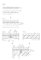
- a method for manufacturing the skinned product 10 configured as described above will be described with reference to FIGS. 1 (a) to 1 (e).
- a laminated material forming step, a stitch line forming step, and a pasting step are sequentially performed. Next, each step will be described.
- an outer skin 13 and a cushion layer 14 are prepared as shown in FIG.
- the cushion layer 14 is disposed on the back side of the skin 13, and the cushion layer 14 is bonded to the skin 13 with an adhesive.
- stacked the cushion layer 14 on the back surface of the outer skin 13 is formed.
- the cushion layer 14 is softer than the skin 13, the above sewing is performed while the cushion layer 14 is pulled toward the skin 13. By this sewing, the peripheral portions of the upper thread 18 and the lower thread 19 on the back surface of the cushion layer 14 are recessed toward the skin 13. Further, on the surface of the skin 13, stitch lines 17 (see FIG. 2) formed by a plurality of seams 21 arranged linearly as a whole along the surface are formed.
- the cushion layer 14 composed of the three-dimensional knitted cushion layer has excellent compression characteristics (high rigidity) compared to other types of cushion layers. Therefore, when the cushion layer 14 and the skin 13 are stitched together, only the portion close to the stitch line 17 in the cushion layer 14 is pulled toward the skin 13 and compressed. In the cushion layer 14, the thickness near the stitch line 17 is smaller than the thickness of other portions.
- a substrate 11 Prior to performing the pasting step, a substrate 11 is prepared as shown in FIG.
- the base material 11 is formed into a predetermined product shape by a resin molding method such as injection molding.
- an adhesive is applied to at least one of the front surface of the base material 11 and the back surface of the laminated material 12 (cushion layer 14). And it is affixed in the state which is the back surface of the laminated material 12, Comprising: The substantially whole surface including the back surface of the part stitched together, Here, the substantially whole surface of the back surface of the cushion layer 14 was contact
- the base material 11 and the laminated material 12 that are superposed on each other are pressed in directions approaching each other by a press machine (not shown) from both sides in the thickness direction thereof.
- This pressing force acts against the elastic restoring force of the cushion layer 14 of the laminated material 12, and the cushion layer 14 is compressed toward the base material 11.
- the portion of the cushion layer 14 that was pulled and depressed toward the outer skin 13 by sewing before the attaching step is pulled back toward the base material 11 and is not sewn and not depressed. It deforms into a shape along the surface of the substrate 11. That is, the cushion layer 14 of the laminated material 12 is brought into close contact with the base material 11 and is suitably attached to the base material 11. At the time of this pasting, it is not necessary to strictly align the laminated material 12 with respect to the base material 11.
- the pressing force by the press machine is released. Then, the force for compressing the cushion layer 14 is lost, and the cushion layer 14 tries to return to the original state by its own elastic restoring force.
- restoration by the elastic restoring force is limited by the upper thread 18 and the lower thread 19. Therefore, as shown in FIG.1 (e), the shape which reversed the shape before a sticking process is formed in a part of laminated material 12 (skin 13 and cushion layer 14). That is, a recess 15 having a stitch line 17 at the bottom while being recessed toward the substrate 11 in a part of the skin.
- the cushion layer 14 composed of the three-dimensional knitted cushion layer has superior compression characteristics and higher rigidity than other types of cushion layers. Therefore, when the laminated material 12 is stuck to the base material 11 in a close contact state, a clear recess 15 is formed only in a portion near the stitch line 17.
- the stitch line 17 is formed on the surface of the skin 13 by stitching the cushion layer 14 and the skin 13 so that a part of the cushion layer 14 in the laminated material 12 is recessed toward the skin 13.
- pasting step pasting is performed in a state in which the back surface of the laminated material 12 and the substantially entire surface including the back surfaces of the stitched portions (substantially the entire back surface of the cushion layer 14) is in close contact with the base material 11 (FIG. 1). (E)).
- the product 10 with the skin having the recess 15 in a part of the skin 13 and the stitch line 17 at the bottom of the recess 15 without performing a strict alignment operation.
- stacked the cushion layer 14 comprised from a three-dimensional knitted cushion layer on the skin 13 is used.
- the pressing force is applied to the base material 11 and the laminated material 12 from both sides in the thickness direction in a direction in which the base material 11 and the laminated material 12 approach each other.
- the force to apply is released.
- the cushion layer 14 is compressed toward the base material 11 by applying the pressing force. Therefore, it is possible to suitably paste the laminated material 12 in a state where the substantially entire surface including the back surfaces of the stitched portions (substantially the entire back surface of the cushion layer 14) is in close contact with the base material 11.
- the unsewn portion in the cushion layer 14 is restored by its own elastic restoring force, while the stitched portion is restored by the elastic restoring force by the thread. Limited. Therefore, it is possible to suitably form the recessed portion 15 that is recessed toward the base material 11 and has the stitch line 17 at the bottom in a part of the laminated material 12.
- the modified example changed as follows can also be implemented.
- the skin 13 genuine leather may be used instead of synthetic leather.
- cushion layer 14 it may replace with a solid knitted cushion layer and may use foaming materials, such as urethane foam, ethylene foam, and propylene foam. These foams are characterized in that the bubbles are in communication and are soft and have restorability.
- the cushion layer 14 may be attached to the skin 13 with a double-sided tape or an adhesive instead of the adhesive.
- the laminated material 12 may be attached to the base material 11 with a double-sided tape or an adhesive instead of the adhesive.
- the stitch line 17 may be arranged linearly as a whole by arranging a plurality of seams 21 in an inclined state with respect to the direction in which the recess 15 extends. .
- Such an arrangement form of the seams 21 is called an oblique stitch, an inclined stitch or the like.
- the stitch line 17 may be one in which the above-described straight stitch and inclined stitch are alternately arranged.
- the above manufacturing method can also be applied to a product 10 with a skin in a form called “single stitch” or “double stitch” in which a pair of laminated materials 12 are combined as shown in FIGS.
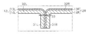
- in-stitch a form called “in-stitch” shown in FIG. 6 is adopted as an intermediate stage.
- the pair of laminated materials 12L and 12R are overlapped with the skins 13L and 13R being adjacent to each other.
- the same pair of laminated materials 12L and 12R are joined together by sewing their peripheral portions.
- the portions of the pair of laminated materials 12L and 12R except for the seams 31L and 31R (hereinafter referred to as “non-sewn portions 32L and 32R”) are opened so as to be separated from each other, whereby the skin 13L in the non-sewn portions 32L and 32R.
- the sewing margins 31L and 31R are in a state where they overlap each other or are close to each other, and are arranged substantially orthogonal to the non-sewn portions 32L and 32R on the back side (the lower side in FIG. 6).
- the stitching portion 33 and both seam allowances 31L and 31R are invisible or difficult to see from the front side (upper side in FIG. 6).
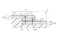
- FIG. 3 shows a state in which a pair of laminated materials 12L and 12R are joined in a form called single stitch as a first modification of a product with a skin.
- the back surface of the seam allowance 31L is the back surface of the non-sewn portion 32L in a state where the seam allowances 31L and 31R in the pair of laminated materials 12L and 12R respectively joined by in-stitch (see FIG. 6) are overlapped with each other And is overlapped on the back surface of the non-sewn portion 32L.
- a stitch line formation process is implemented with respect to these non-sewing parts 32L and both seam allowances 31L and 31R.
- substantially the entire back surface of the laminated materials 12L and 12R including the back surface of the stitched portion is attached to the base material 11.
- most of the back surface of the non-sewn portion 32L (cushion layer 14L) shown in FIG. 3 and each back surface of the seam allowance 31R and the non-sewn portion 32R (both cushion layers 14R) are attached in the pasting step. It is an object to be affixed to the substrate 11.
- the base material 11 used in the first modification has a stepped portion 34.
- each seam allowance 31L, 31R of laminated material 12L, 12R is arrange
- the recess 15L having the stitch line 17L at the bottom is formed above the seams 31L and 31R in the non-sewn part 32L.
- FIG. 4 shows a state in which a pair of laminated materials 12L and 12R are joined in a form called a double stitch as a second modification of the product with skin.
- both seam allowances 31L and 31R in the pair of laminated materials 12L and 12R respectively joined by in-stitch (FIG. 6) are opened so as to be separated from each other.
- the seam allowance 31L shown in FIG. 4 is such that the back surface of the seam allowance 31L is bent toward the back surface of the non-sewn portion 32L, and is superimposed on the back surface of the non-sewn portion 32L. And a stitch line formation process is implemented with respect to these non-sewing parts 32L and the seam allowance 31L. Further, the substantially entire surface including the back surface of the stitched portion, which is the back surface of the laminated material 12L, in this case, the outer skin 13L of the seam allowance 31L and the majority of the back surface of the non-sewn portion 32L (cushion layer 14L) are pasted. In FIG.
- the back surface of the seam allowance 31R is bent toward the back surface of the non-sewn portion 32R, and is overlapped with the back surface of the non-sewn portion 32R. And a stitch line formation process is implemented with respect to these non-sewing parts 32R and the sewing allowance 31R.
- the substantially entire surface including the back surface of the stitched portion which is the back surface of the laminated material 12R, in this case, the skin 13R of the seam allowance 31R and the majority of the back surface of the non-sewn portion 32R (cushion layer 14R) are pasted.
- the base material 11 used in the second modification has a recess 35.
- each seam allowance 31L, 31R of each laminated material 12L, 12R is arrange
- the recessed portions 15L and 15R having the stitch lines 17L and 17R at the bottom are formed above the seams 31L and 31R in the non-sewn portions 32L and 32R.
- a decorative stitch similar to that in the above embodiment may be formed on each of the non-sewn portions 32L and 32R of the pair of laminated materials 12L and 12R joined in a form called the in-stitch (FIG. 6).
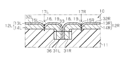
- FIG. 5 An example thereof is shown in FIG. 5 as a third modification of the product with skin.
- both seam allowances 31L and 31R are not overlapped unlike the single stitch and double stitch.
- the sewing allowances 31L and 31R are substantially orthogonal to the back surfaces (the lower side in FIG. 5) of both the non-sewn portions 32L and 32R.
- a stitch line forming step is performed on each non-sewn portion 32L, 32R.
- substantially the entire back surface of the laminated materials 12L and 12R including the back surface of the stitched portion is attached to the base material 11.
- the back surface of each non-sewing part 32L, 32R becomes a target stuck on the base material 11 in a sticking process.
- the recessed portions 15L and 15R having the stitch lines 17L and 17R at the bottom are formed in the non-sewn portions 32L and 32R.
- the base material 11 used in the third modification has a recess 36. Both seam allowances 31L and 31R are disposed in the recess 36.
- the above manufacturing method is not limited to automobile interior parts, and can be widely applied to products with a skin having the stitch line 17 on the surface of the skin 13.
Landscapes
- Engineering & Computer Science (AREA)
- Mechanical Engineering (AREA)
- Laminated Bodies (AREA)
- Vehicle Step Arrangements And Article Storage (AREA)
- Lining Or Joining Of Plastics Or The Like (AREA)
- Vehicle Interior And Exterior Ornaments, Soundproofing, And Insulation (AREA)
Abstract
基材(11)と、表皮(13)及びクッション層(14)から構成される積層材(12)と、表皮(13)の表面に沿って線状に配列された複数の縫い目により構成されるステッチライン(17)とを備える表皮付き製品(10)の製造に際し、ステッチライン形成工程及び貼付け工程が行なわれる。ステッチライン形成工程では、積層材(12)のクッション層(14)の一部が表皮(13)に向かって窪むように、クッション層(14)及び表皮(13)を上糸(18)及び下糸(19)で縫い合わせ、表皮(13)の表面にステッチライン(17)が形成される。貼付け工程では、積層材(12)の裏面であって、縫い合わされた部分の裏面を含む略全面を基材(11)に対し密着させた状態で貼付ける。
Description
本発明は、表皮の表面の一部にステッチラインが形成された表皮付き製品を製造する方法に関する。
自動車のインストルメントパネル、コンソール等の内装品として、基材と、同基材上に設けられ、かつ表皮の裏側にクッション層を積層して構成される積層材と、表皮の表面に沿って線状に配列された複数の縫い目により構成されるステッチラインとを備えるもの(以下、表皮付き製品という)が知られている。この表皮付き製品では、表皮の一部に窪み部を有し、その窪み部の底部にステッチラインが位置していてステッチラインが沈み込んだように見えることが、質感を高めるうえで有効である。
特許文献1に記載された「車両内装部材の製造方法」では、図7に示すように、積層材51にステッチライン形成部55が設けられている。ステッチライン形成部55では、表皮52及びクッション層53の各表面が基材56に向かって窪み、各裏面が基材56に向かって突出している。ステッチライン形成部55においてクッション層53と表皮52とが縫い合わされることで、表皮52の表面にステッチライン54が形成される。
一方、基材56にはステッチライン対応部57が設けられている。ステッチライン対応部57は、基材56の表面が裏面に向かって窪んでいる。
そして、ステッチライン形成部55がステッチライン対応部57に貼り合わされることで、積層材51が基材56に固定される。
そして、ステッチライン形成部55がステッチライン対応部57に貼り合わされることで、積層材51が基材56に固定される。
ところが、特許文献1に記載された製造方法では、積層材51を基材56に固定する際に、ステッチライン対応部57に対するステッチライン形成部55の位置合わせ作業を厳密に行なわなければならず手間がかかる。
本発明は、このような実情に鑑みてなされたものであって、その目的は、表皮の一部に窪み部を有し、その窪み部の底部にステッチラインを有する表皮付き製品を、厳密な位置合わせ作業をせずに製造することのできる表皮付き製品の製造方法を提供することにある。
上記課題を解決する表皮付き製品の製造方法は、表面及び裏面を有する表皮と、表面及び裏面を有する基材と、前記基材の表面上に設けられ、かつ前記表皮の裏面に、同表皮よりも柔らかいクッション層を積層して構成される積層材と、前記表皮の表面に沿って線状に配列された複数の縫い目により構成されるステッチラインとを備える表皮付き製品を製造する方法であって、前記積層材における前記クッション層の一部が前記表皮に向かって窪むように前記クッション層と前記表皮とを縫い合わせることにより、前記表皮の表面に前記ステッチラインを形成する工程と、前記積層材の裏面であって、前記縫い合わされた部分の裏面を含む略全面を前記基材に対し密着させた状態で貼付ける工程とが少なくとも行なわれる。
ステッチライン形成工程では、積層材におけるクッション層と表皮とが縫い合わされる。積層材におけるクッション層は表皮よりも柔らかいため、クッション層と表皮とが縫い合わされるとき、クッション層の一部が糸によって表皮に向かって引張られる。そのため、クッション層の裏面における同糸の周辺部分は表皮に向かって窪む。また、表皮の表面には、同表面に沿って線状に配列された複数の縫い目から構成されるステッチラインが形成される。
貼付け工程では、積層材の裏面であって、縫い合わされた部分の裏面を含む略全面が基材に対し密着させられた状態で貼付けられる。この際、クッション層において、貼付け工程の前に、縫い合わせにより表皮に向かって引張られて窪んでいた部分は基材に向かって引き戻され、縫い合わされず窪んでいない部分と同様に基材の表面に沿った形状にされて、同基材に貼付けられる。この貼付けにおいて、積層材を基材に対し厳密に位置合わせする必要はない。
上記の貼付けにより、積層材の一部に、貼付け工程の前の形状を反転した形状が形成される。すなわち、表皮の一部に基材に向かって窪むとともに底部にステッチラインを有する窪み部が形成される。
積層材としては、表皮に立体編クッション層が積層されたものが適している。立体編クッション層は、他の種類のクッション層に比べ圧縮特性に優れる(剛性が高い)。そのため、ステッチライン形成工程で立体編クッション層と表皮とが縫い合わされた場合、立体編クッション層のうちステッチラインに近い部分のみが表皮に向かって引張られる。
また、貼付け工程で、積層材が基材に密着状態で貼付けられた場合、ステッチラインに近い部分のみに明確な窪み部が形成される。
上記表皮付き製品の製造方法において、貼付け工程では、前記基材及び前記積層材の少なくとも一方に対し、互いに接近させる方向へ押付ける力が加えられ、前記積層材が前記基材に貼付けられた後に前記押付ける力が解除されることが好ましい。
上記表皮付き製品の製造方法において、貼付け工程では、前記基材及び前記積層材の少なくとも一方に対し、互いに接近させる方向へ押付ける力が加えられ、前記積層材が前記基材に貼付けられた後に前記押付ける力が解除されることが好ましい。
上記の製造方法によれば、貼付け工程では、基材及び積層材の少なくとも一方に対し、互いに接近させる方向へ押付ける力が加えられる。この力はクッション層の弾性復元力に抗して作用し、クッション層は基材に向かって圧縮される。よって、積層材の裏面であって、縫い合わされた部分の裏面を含む略全面が基材に密着した状態で好適に貼付けられる。この際、クッション層のうち、貼付け工程の前に、縫い合わせにより表皮に向かって引張られて窪んでいた部分も基材に向かって引き戻されて、縫い合わされず窪んでいない部分と同様に基材の表面に沿った形状となり、同基材に貼付けられる。
積層材が基材に貼付けられた後に上記押付ける力は解除される。すると、クッション層を圧縮させる力がなくなり、同クッション層が自身の弾性復元力により元の状態に戻ろうとする。但し、クッション層において縫い合わされた部分では、糸により弾性復元力による復元が制限される。そのため、積層材の一部に、貼付け工程の前の形状を反転した形状が形成される。すなわち、表皮の一部に基材に向かって窪むとともに底部にステッチラインを有する窪み部が形成される。
上記表皮付き製品の製造方法によれば、表皮の一部に窪み部を有し、その窪み部の底部にステッチラインを有する表皮付き製品を、厳密な位置合わせ作業をせずに製造することができる。
以下、表皮付き製品の製造方法の一実施形態について、図1及び図2を参照して説明する。
まず、本実施形態の製造方法により製造される表皮付き製品について説明する。本実施形態では、自動車のインストルメントパネル、コンソール、ドアトリム、グローブボックス、ピラーガーニッシュ等の各種自動車用内装品を、表皮付き製品の対象としている。説明の便宜上、表皮付き製品を単純な形状で例示する。
まず、本実施形態の製造方法により製造される表皮付き製品について説明する。本実施形態では、自動車のインストルメントパネル、コンソール、ドアトリム、グローブボックス、ピラーガーニッシュ等の各種自動車用内装品を、表皮付き製品の対象としている。説明の便宜上、表皮付き製品を単純な形状で例示する。
図2に示すように、表皮付き製品10は、基材11、積層材12及びステッチライン17を主要な構成部材として備えている。次に、表皮付き製品10の各構成部材について説明する。
<基材11>
基材11は、表皮付き製品10の骨格をなす部材であり、表皮付き製品10の剛性を担保している。基材11は、ポリプロピレン、ポリエチレン等の樹脂材料を用い、射出成形等の樹脂成形によって、製品形状に形成されている。基材11は、曲面、屈曲面、凹凸面等といった平坦でない表面を有するものであってもよい。
基材11は、表皮付き製品10の骨格をなす部材であり、表皮付き製品10の剛性を担保している。基材11は、ポリプロピレン、ポリエチレン等の樹脂材料を用い、射出成形等の樹脂成形によって、製品形状に形成されている。基材11は、曲面、屈曲面、凹凸面等といった平坦でない表面を有するものであってもよい。
基材11には、特許文献1のステッチライン対応部57(図7参照)に相当する部分、すなわち、表面が裏面に向かって窪むとともに、積層材のステッチライン形成部を貼り合せるための部分は形成されていない。
<積層材12>
積層材12は、表皮付き製品10の表層部分に対応する部材である。積層材12の裏面が基材11の表面に密着させられた状態で積層材12が基材11に貼付けられることで、積層材12は基材11上に配置されている。
積層材12は、表皮付き製品10の表層部分に対応する部材である。積層材12の裏面が基材11の表面に密着させられた状態で積層材12が基材11に貼付けられることで、積層材12は基材11上に配置されている。
積層材12は、表皮付き製品10の意匠面を構成する表皮13と、表皮13の裏面(図2の下側)に積層され、かつ表皮13よりも柔らかいクッション層14とから構成される。
表皮13は、主として表皮付き製品10の質感向上、触感向上を目的として用いられている。表皮13は、塩化ビニル、熱可塑性エラストマ(TPE)等から作られる合成皮革によって、厚みの均一なシート状に形成されており、厚み方向等に変形し得る。
表皮13の厚みは、0.35~1.5mmであることが望ましい。表皮13の厚みが0.35mmよりも小さいと、表皮付き製品10の製造の過程で表皮13におけるステッチライン17に近い部分にシワが入るおそれがある。これに対し、表皮13の厚みが1.5mmよりも大きいと、表皮13が硬くなる。表皮13が硬いと、積層材12が基材11に貼付けられる際に、表皮13が基材11に沿って変形しにくく、窪み部15が形成されにくい。表皮13の表面に、皮革製品に見られるようなシボ(皺模様)が形成されていてもよい。
クッション層14は立体編クッション層によって構成され、弾力性を有している。クッション層14は、表皮付き製品10の触感向上のために用いられており、例えば、ダブルラッセル編機を用いて形成され、所定間隔をおいて配置される一対のグランド編地間にて連結糸を往復させることにより編成される。
クッション層14の厚みは、1.5~3.5mmであることが望ましい。厚みが上記範囲から外れると、表皮付き製品10の見栄えが低下する。具体的には、クッション層14の厚みが1.5mmよりも小さいと、クッション層14が基材11に貼付けられたときに、クッション層14において基材11に向かって引き戻される量が不足する。クッション層14の厚みが3.5mmよりも大きいと、クッション層14と表皮13とが縫い合わされたときにクッション層14が表皮13に向かって過剰に窪むおそれがある。この場合、積層材12が基材11に貼付けられたときのクッション層14の基材11に向かう引き戻し量が多くなり、積層材12の表面に、意図するよりも大きな窪み部15が形成されるおそれがある。
積層材12の表面には、クッション層14の一部が基材11に向かって圧縮変形させられることにより、一対の壁面16から構成される窪み部15が形成されている。クッション層14において、窪み部15が形成された部分の厚みは、窪み部15が形成されていない部分の厚みよりも小さい。一対の壁面16は、窪み部15の底部に向けてなだらかに傾斜している。一対の壁面16の間隔は、窪み部15の底部に近づくに従って狭められている。
積層材12には、特許文献1のステッチライン形成部55(図7参照)に相当する部分、すなわち、積層材における表皮及びクッション層の各表面が基材に向かって窪み、かつ、同表皮及びクッション層の各裏面が基材に向かって突出している部分は形成されていない。
<ステッチライン17>
ステッチライン17は、表皮付き製品10に対する装飾を目的として設けられている。表皮付き製品10の表皮13では、表皮13を構成するパーツの縫い合わせを擬似的に再現することで、本革の表皮を使用しているような外観を表皮付き製品10に持たせて高級感を演出している。こうした形態のステッチライン17は、飾りステッチとも呼ばれる。
ステッチライン17は、表皮付き製品10に対する装飾を目的として設けられている。表皮付き製品10の表皮13では、表皮13を構成するパーツの縫い合わせを擬似的に再現することで、本革の表皮を使用しているような外観を表皮付き製品10に持たせて高級感を演出している。こうした形態のステッチライン17は、飾りステッチとも呼ばれる。
ステッチライン17は、表皮13とクッション層14とを、上糸18及び下糸19を用いて縫い合わせることにより形成されており、表皮13の表面に形成される窪み部15の底部に沿って線状に配列された複数の縫い目21から構成される。換言すると、上糸18が窪み部15の底部に断続的に現出しており、この現出部分が縫い目21を構成している。本実施形態のステッチライン17は、複数の縫い目21が、窪み部15の延びる方向に沿って直線状に配列されることによって構成されている。このような縫い目21の配列形態は、ストレートステッチとも呼ばれる。
次に、本実施形態の作用として、上記のように構成された表皮付き製品10を製造する方法について、図1(a)~(e)を参照して説明する。
この製造方法では、積層材形成工程、ステッチライン形成工程及び貼付け工程が順に行なわれる。次に、各工程について説明する。
この製造方法では、積層材形成工程、ステッチライン形成工程及び貼付け工程が順に行なわれる。次に、各工程について説明する。
<積層材形成工程>
積層材形成工程では、図1(a)に示すように、表皮13とクッション層14とが準備される。クッション層14は表皮13の裏側に配置され、クッション層14は接着剤によって表皮13に接着される。そして、図1(b)に示すように、表皮13の裏面にクッション層14を積層した積層材12が形成される。
積層材形成工程では、図1(a)に示すように、表皮13とクッション層14とが準備される。クッション層14は表皮13の裏側に配置され、クッション層14は接着剤によって表皮13に接着される。そして、図1(b)に示すように、表皮13の裏面にクッション層14を積層した積層材12が形成される。
<ステッチライン形成工程>
ステッチライン形成工程では、図1(c)に示すように、上糸18及び下糸19で積層材12が表面と裏面の両面にわたって縫われることで、表皮13とクッション層14とが縫い合わされる。この縫い合わせにはミシンが用いられる。
ステッチライン形成工程では、図1(c)に示すように、上糸18及び下糸19で積層材12が表面と裏面の両面にわたって縫われることで、表皮13とクッション層14とが縫い合わされる。この縫い合わせにはミシンが用いられる。
ここで、クッション層14が表皮13よりも柔らかいことから、上記縫い合わせは、クッション層14が表皮13に向かって引張られながら行なわれる。この縫い合わせにより、クッション層14の裏面における上糸18及び下糸19の周辺部分が表皮13に向かって窪む。また、表皮13の表面には、同表面に沿って全体として線状に配列された複数の縫い目21から構成されるステッチライン17(図2参照)が形成される。
立体編クッション層から構成されるクッション層14は、他の種類のクッション層に比べ圧縮特性に優れる(剛性が高い)。そのため、クッション層14と表皮13とが縫い合わされた場合、クッション層14におけるステッチライン17に近い部分のみが表皮13に向かって引張られて、圧縮される。クッション層14においては、ステッチライン17に近い部分の厚みは他の部分の厚みよりも小さい。
<貼付け工程>
貼付け工程の実施に先立ち、図1(d)に示すように基材11が準備される。基材11は、射出成形等の樹脂成形方法によって所定の製品形状に成形されたものである。
貼付け工程の実施に先立ち、図1(d)に示すように基材11が準備される。基材11は、射出成形等の樹脂成形方法によって所定の製品形状に成形されたものである。
貼付け工程では、基材11の表面及び積層材12(クッション層14)の裏面の少なくとも一方に接着剤が塗布される。そして、積層材12の裏面であって、縫い合わされた部分の裏面を含む略全面、ここでは、クッション層14の裏面の略全面が基材11の表面に対して密着させられた状態で貼付けられる。
本実施形態では、互いに重ね合わされた基材11及び積層材12が、それらの厚み方向における両側から、プレス機(図示略)によって互いに接近する方向へ押付けられる。この押付け力は、積層材12のクッション層14の弾性復元力に抗して作用し、クッション層14は基材11に向かって圧縮される。この際、クッション層14のうち、貼付け工程の前に、縫い合わせにより表皮13に向かって引張られて窪んでいた部分は基材11に向かって引き戻されて、縫い合わされず窪んでいない部分と同様に基材11の表面に沿った形状に変形する。すなわち積層材12のクッション層14が基材11に密着した状態にされて、基材11に好適に貼付けられる。この貼付けに際しては、積層材12を基材11に対し厳密に位置合わせする必要はない。
積層材12(クッション層14)が基材11に貼付けられた後に、プレス機による上記押付け力は解除される。すると、クッション層14を圧縮する力がなくなり、クッション層14は自身の弾性復元力により元の状態に戻ろうとする。但し、クッション層14において縫い合わされた部分では、上糸18及び下糸19により弾性復元力による復元が制限される。そのため、図1(e)に示すように、積層材12(表皮13、クッション層14)の一部に、貼付け工程の前の形状を反転した形状が形成される。すなわち、表皮の一部に基材11に向かって窪むとともに底部にステッチライン17を有する窪み部15が形成される。
ここで、上述したように立体編クッション層から構成されるクッション層14は、他の種類のクッション層に比べ圧縮特性に優れ、剛性が高い。そのため、積層材12が基材11に密着状態で貼付けられた場合、ステッチライン17の近くの部分のみに明確な窪み部15が形成される。
以上詳述した本実施形態によれば、次の効果が得られる。
(1)ステッチライン形成工程では、積層材12におけるクッション層14の一部が表
皮13に向かって窪むようにクッション層14と表皮13とを縫い合わせることにより、表皮13の表面にステッチライン17を形成する(図1(c))。貼付け工程では、積層材12の裏面であって、縫い合わされた部分の裏面を含む略全面(クッション層14の裏面の略全面)を基材11に対し密着させた状態で貼付けている(図1(e))。
(1)ステッチライン形成工程では、積層材12におけるクッション層14の一部が表
皮13に向かって窪むようにクッション層14と表皮13とを縫い合わせることにより、表皮13の表面にステッチライン17を形成する(図1(c))。貼付け工程では、積層材12の裏面であって、縫い合わされた部分の裏面を含む略全面(クッション層14の裏面の略全面)を基材11に対し密着させた状態で貼付けている(図1(e))。
そのため、表皮13の一部に窪み部15を有し、窪み部15の底部にステッチライン17を有する表皮付き製品10を、厳密な位置合わせ作業をせずに製造することができる。
(2)積層材12として、立体編クッション層から構成されるクッション層14を表皮13に積層したもの(図1(b))を用いている。
(2)積層材12として、立体編クッション層から構成されるクッション層14を表皮13に積層したもの(図1(b))を用いている。
そのため、ステッチライン形成工程(図1(c))では、立体編クッション層のうちステッチライン17の近くの部分のみを表皮13に向かって引張り、貼付け工程(図1(e))では、ステッチライン17の近くの部分のみに明確な窪み部15を形成することができる。
(3)貼付け工程では、基材11及び積層材12に対し、それらの厚み方向における両側から、互いに接近させる方向へ押付ける力を加え、積層材12が基材11に貼付けられた後に上記押付ける力を解除している。
そのため、上記押付ける力を加えることにより、クッション層14は基材11に向かって圧縮される。よって、積層材12の裏面であって、縫い合わされた部分の裏面を含む略全面(クッション層14の裏面の略全面)を基材11に密着させた状態で好適に貼付けることができる。
また、上記貼付けの後に押付ける力を解除することにより、クッション層14における縫い合わされていない部分は、自身の弾性復元力により復元する一方、縫い合わされた部分は、糸により弾性復元力による復元が制限される。そのため、積層材12の一部に、基材11に向かって窪むとともに底部にステッチライン17を有する窪み部15を好適に形成することができる。
なお、上記実施形態に対し、以下のように変更した変形例を実施することもできる。
・表皮13として、合成皮革に代えて本革を用いてもよい。
・クッション層14として、立体編クッション層に代えて、ウレタンフォーム、エチレンフォーム、プロピレンフォーム等の発泡材を用いてもよい。これらの発泡材には、気泡が連通していて柔らかく、復元性を有するという特徴がある。
・表皮13として、合成皮革に代えて本革を用いてもよい。
・クッション層14として、立体編クッション層に代えて、ウレタンフォーム、エチレンフォーム、プロピレンフォーム等の発泡材を用いてもよい。これらの発泡材には、気泡が連通していて柔らかく、復元性を有するという特徴がある。
・積層材形成工程において、クッション層14は表皮13に対し、接着剤に代えて両面テープ又は粘着剤により貼付けられてもよい。
同様に、貼付け工程において、積層材12は基材11に対し、接着剤に代えて両面テープ又は粘着剤により貼付けられてもよい。
同様に、貼付け工程において、積層材12は基材11に対し、接着剤に代えて両面テープ又は粘着剤により貼付けられてもよい。
・ステッチライン17は、複数の縫い目21が、窪み部15の延びる方向に対し、それぞれ一定の角度で傾斜した状態で配列されることにより、全体として線状に配列されたものであってもよい。このような縫い目21の配列形態は、斜めステッチ、傾斜ステッチ等と呼ばれる。さらに、ステッチライン17は、上述したストレートステッチと傾斜ステッチとが交互に配列されたものであってもよい。
・上記製造方法は、図3及び図4に示すように一対の積層材12が結合された「シングルステッチ」、「ダブルステッチ」と呼ばれる形態の表皮付き製品10にも適用可能である。
次に、それぞれ一対の積層材12、表皮13、クッション層14などを備えた製品について説明する。この場合、図面の左側に位置する要素については符号の後に「L」を付し、図面の右側に位置する要素については符号の後に「R」を付する。
上記形態において一対の積層材12L,12Rが結合される場合には、途中の段階として、図6に示す「インステッチ」と呼ばれる形態が採用される。
インステッチでは、各表皮13L,13Rが隣り合う状態で一対の積層材12L,12Rが重ねられる。同一対の積層材12L,12Rは、それぞれの周縁部が縫い合わされることで結合される。そして、一対の積層材12L,12Rにおける各縫い代31L,31Rを除く部分(以下、「非縫製部32L,32R」という)が互いに離れるように開かれることにより、非縫製部32L,32Rにおける表皮13L,13Rがそれぞれ表側に配置される。縫い代31L,31Rは互いに重なった状態、又は接近した状態となり、非縫製部32L,32Rに対しては、それらの裏側(図6の下側)で略直交して配置される。縫合部33及び両縫い代31L,31Rは、表側(図6の上側)からは見えない、又は見えにくい。
インステッチでは、各表皮13L,13Rが隣り合う状態で一対の積層材12L,12Rが重ねられる。同一対の積層材12L,12Rは、それぞれの周縁部が縫い合わされることで結合される。そして、一対の積層材12L,12Rにおける各縫い代31L,31Rを除く部分(以下、「非縫製部32L,32R」という)が互いに離れるように開かれることにより、非縫製部32L,32Rにおける表皮13L,13Rがそれぞれ表側に配置される。縫い代31L,31Rは互いに重なった状態、又は接近した状態となり、非縫製部32L,32Rに対しては、それらの裏側(図6の下側)で略直交して配置される。縫合部33及び両縫い代31L,31Rは、表側(図6の上側)からは見えない、又は見えにくい。
図3は、表皮付き製品の第1の変形例としてシングルステッチと呼ばれる形態において一対の積層材12L,12Rが結合された状態を示している。第1の変形例では、インステッチ(図6参照)でそれぞれ結合された一対の積層材12L,12Rにおける縫い代31L,31Rが互いに重ねられた状態で、縫い代31Lの裏面が非縫製部32Lの裏面に向かって折り曲げられ、非縫製部32Lの裏面に重ねられる。そして、これらの非縫製部32L及び両縫い代31L,31Rに対し、ステッチライン形成工程が実施される。また、積層材12L,12Rの裏面であって、縫い合わされた部分の裏面を含む略全面が基材11に貼付けられる。第1の変形例では、図3に示す非縫製部32L(クッション層14L)の裏面の大部分と、縫い代31R及び非縫製部32R(ともにクッション層14R)の各裏面とが、貼付け工程において、基材11に貼付けられる対象である。
図3に示すように、第1の変形例で用いられる基材11は段差部34を有する。そして、積層材12L,12Rの各縫い代31L,31Rが段差部34に配置されて、上記の貼付けが実施される。この貼付けにより、底部にステッチライン17Lを有する窪み部15Lは、非縫製部32Lにおいて縫い代31L,31Rの上側に形成される。
図4は、表皮付き製品の第2の変形例としてダブルステッチと呼ばれる形態において一対の積層材12L,12Rが結合された状態を示している。第2の変形例では、インステッチ(図6)でそれぞれ結合された一対の積層材12L,12Rにおける両縫い代31L,31Rが互いに離れるように開かれる。
すなわち、図4に示す縫い代31Lは、縫い代31Lの裏面が非縫製部32Lの裏面に向かって折り曲げられ、非縫製部32Lの裏面に重ねられる。そして、これらの非縫製部32L及び縫い代31Lに対し、ステッチライン形成工程が実施される。また、積層材12Lの裏面であって、縫い合わされた部分の裏面を含む略全面、この場合、縫い代31Lの表皮13Lと非縫製部32L(クッション層14L)の裏面の大部分とが、貼付け工程において、基材11に貼付けられる対象である。
また、図4に示す縫い代31Rは、縫い代31Rの裏面が非縫製部32Rの裏面に向かって折り曲げられ、非縫製部32Rの裏面に重ねられる。そして、これらの非縫製部32R及び縫い代31Rに対し、ステッチライン形成工程が実施される。また、積層材12Rの裏面であって、縫い合わされた部分の裏面を含む略全面、この場合、縫い代31Rの表皮13Rと非縫製部32R(クッション層14R)の裏面の大部分とが、貼付け工程において、基材11に貼付けられる対象である。
図4に示すように、第2の変形例で用いられる基材11は凹部35を有する。そして、各積層材12L,12Rの各縫い代31L,31Rが凹部35内に配置されて、上記の貼付けが実施される。この貼付けにより、底部にステッチライン17L,17Rを有する窪み部15L,15Rは、各非縫製部32L,32Rにおいて各縫い代31L,31Rの上側に形成される。
・上記インステッチ(図6)と呼ばれる形態で結合された一対の積層材12L,12Rの非縫製部32L,32Rのそれぞれに対し、上記実施形態と同様の飾りステッチが形成されてもよい。その一例を表皮付き製品の第3の変形例として図5に示す。
図5に示すように第3の変形例では、両縫い代31L,31Rは、上記シングルステッチやダブルステッチとは異なり重ね合わされない。縫い代31L,31Rは、両非縫製部32L,32Rに対し、それらの裏面(図5の下側)に略直交している。各非縫製部32L,32Rに対し、ステッチライン形成工程が実施される。また、積層材12L,12Rの裏面であって、縫い合わされた部分の裏面を含む略全面が基材11に貼り付けられる。図5に示す第3の変形例では、少なくとも各非縫製部32L,32Rの裏面が、貼付け工程において、基材11に貼付けられる対象となる。この貼付けにより、底部にステッチライン17L,17Rを有する窪み部15L,15Rは、各非縫製部32L,32Rに形成される。
図5に示すように、第3の変形例で用いられる基材11は凹部36を有する。そして、両縫い代31L,31Rは凹部36内に配置される。
・上記製造方法は、自動車用内装品に限らず、ステッチライン17を表皮13の表面に有する表皮付き製品に広く適用可能である。
・上記製造方法は、自動車用内装品に限らず、ステッチライン17を表皮13の表面に有する表皮付き製品に広く適用可能である。
10…表皮付き製品、11…基材、12,12L,12R…積層材、13,13L,13R…表皮、14,14L,14R…クッション層、15,15L,15R…窪み部、17,17L,17R…ステッチライン、21…縫い目。
Claims (3)
- 表面及び裏面を有する表皮と、表面及び裏面を有する基材と、
前記基材の表面上に設けられ、かつ前記表皮の裏面に、同表皮よりも柔らかいクッション層を積層して構成される積層材と、
前記表皮の表面に沿って線状に配列された複数の縫い目により構成されるステッチラインと
を備える表皮付き製品を製造する方法であって、
前記積層材における前記クッション層の一部が前記表皮に向かって窪むように前記クッション層と前記表皮とを縫い合わせることにより、前記表皮の表面に前記ステッチラインを形成する工程と、
前記積層材の裏面であって、前記縫い合わされた部分の裏面を含む略全面を前記基材に対し密着させた状態で貼付ける工程と
が少なくとも行なわれることを特徴とする表皮付き製品の製造方法。 - 前記積層材として、前記表皮に立体編クッション層が積層されたものが用いられる請求項1に記載の表皮付き製品の製造方法。
- 前記貼付ける工程では、前記基材及び前記積層材の少なくとも一方に対し、互いに接近させる方向へ押付ける力が加えられ、前記積層材が前記基材に貼付けられた後に前記押付ける力が解除され、それによって前記表皮の一部に窪みが形成される請求項1又は2に記載の表皮付き製品の製造方法。
Applications Claiming Priority (2)
| Application Number | Priority Date | Filing Date | Title |
|---|---|---|---|
| JP2013241738A JP5891215B2 (ja) | 2013-11-22 | 2013-11-22 | 表皮付き製品の製造方法 |
| JP2013-241738 | 2013-11-22 |
Publications (1)
| Publication Number | Publication Date |
|---|---|
| WO2015076341A1 true WO2015076341A1 (ja) | 2015-05-28 |
Family
ID=53179601
Family Applications (1)
| Application Number | Title | Priority Date | Filing Date |
|---|---|---|---|
| PCT/JP2014/080792 Ceased WO2015076341A1 (ja) | 2013-11-22 | 2014-11-20 | 表皮付き製品の製造方法 |
Country Status (2)
| Country | Link |
|---|---|
| JP (1) | JP5891215B2 (ja) |
| WO (1) | WO2015076341A1 (ja) |
Families Citing this family (5)
| Publication number | Priority date | Publication date | Assignee | Title |
|---|---|---|---|---|
| JP2017171181A (ja) * | 2016-03-24 | 2017-09-28 | テイ・エス テック株式会社 | 車両用内装品及びその製造方法 |
| JP6597529B2 (ja) * | 2016-09-08 | 2019-10-30 | トヨタ車体株式会社 | 内装部品及びその製造方法 |
| JP7059152B2 (ja) * | 2017-11-16 | 2022-04-25 | しげる工業株式会社 | 自動車の内装部品の製造方法 |
| JP7447832B2 (ja) * | 2021-01-19 | 2024-03-12 | トヨタ車体株式会社 | ステッチ加飾部品およびその製造方法 |
| JP7576803B2 (ja) * | 2022-08-02 | 2024-11-01 | 住江織物株式会社 | 車輌内装用加飾シート材 |
Citations (6)
| Publication number | Priority date | Publication date | Assignee | Title |
|---|---|---|---|---|
| JPS6430213U (ja) * | 1987-08-19 | 1989-02-23 | ||
| JP2005212589A (ja) * | 2004-01-29 | 2005-08-11 | Toyota Motor Corp | 車両内装用シート |
| JP2009196610A (ja) * | 2008-02-25 | 2009-09-03 | Calsonic Kansei Corp | 内装部品縫製部構造 |
| JP2010036839A (ja) * | 2008-08-08 | 2010-02-18 | Nippon Plast Co Ltd | 加飾パネル、収納ボックス、及び加飾パネルの製造方法 |
| US20100171333A1 (en) * | 2007-01-05 | 2010-07-08 | Johnson Controls Technology Company | Localized deep soft area of a trim panel |
| JP2013043571A (ja) * | 2011-08-24 | 2013-03-04 | Inoac Corp | 車両内装部材の製造方法 |
Family Cites Families (1)
| Publication number | Priority date | Publication date | Assignee | Title |
|---|---|---|---|---|
| JPH01136044U (ja) * | 1988-03-07 | 1989-09-18 |
-
2013
- 2013-11-22 JP JP2013241738A patent/JP5891215B2/ja active Active
-
2014
- 2014-11-20 WO PCT/JP2014/080792 patent/WO2015076341A1/ja not_active Ceased
Patent Citations (6)
| Publication number | Priority date | Publication date | Assignee | Title |
|---|---|---|---|---|
| JPS6430213U (ja) * | 1987-08-19 | 1989-02-23 | ||
| JP2005212589A (ja) * | 2004-01-29 | 2005-08-11 | Toyota Motor Corp | 車両内装用シート |
| US20100171333A1 (en) * | 2007-01-05 | 2010-07-08 | Johnson Controls Technology Company | Localized deep soft area of a trim panel |
| JP2009196610A (ja) * | 2008-02-25 | 2009-09-03 | Calsonic Kansei Corp | 内装部品縫製部構造 |
| JP2010036839A (ja) * | 2008-08-08 | 2010-02-18 | Nippon Plast Co Ltd | 加飾パネル、収納ボックス、及び加飾パネルの製造方法 |
| JP2013043571A (ja) * | 2011-08-24 | 2013-03-04 | Inoac Corp | 車両内装部材の製造方法 |
Also Published As
| Publication number | Publication date |
|---|---|
| JP2015100955A (ja) | 2015-06-04 |
| JP5891215B2 (ja) | 2016-03-22 |
Similar Documents
| Publication | Publication Date | Title |
|---|---|---|
| US8678458B2 (en) | Vehicle interior components with decorative stitching | |
| JP5891215B2 (ja) | 表皮付き製品の製造方法 | |
| JP5813415B2 (ja) | 車両内装部材の製造方法 | |
| CN104943621B (zh) | 具有覆皮的产品的末端部结构 | |
| JP2011194932A (ja) | 車両用内装品 | |
| CN104053577A (zh) | 用于与车辆内部部件的装饰线迹一起使用的线缝间隔部件 | |
| JP6187410B2 (ja) | ステッチラインの形成方法 | |
| JP2007223368A (ja) | 車両用内装品およびその製造方法 | |
| JP2015160484A (ja) | 自動車用内装品の製造方法及び自動車用内装品 | |
| JP6440460B2 (ja) | 車両用内装部品 | |
| WO2013111680A1 (ja) | 表皮付き樹脂成形品の製造方法 | |
| JP5944163B2 (ja) | 自動車内装品及びその製造方法 | |
| JPS6216817B2 (ja) | ||
| JP5931552B2 (ja) | 車両内装部材およびその製造方法 | |
| JP2010089696A (ja) | 皮革貼り構造、皮革貼り構造の製造方法、及び、自動車内装部品 | |
| JP6886871B2 (ja) | 車両内装部材の製造方法および車両内装部材製造用圧着装置 | |
| JP2010036839A (ja) | 加飾パネル、収納ボックス、及び加飾パネルの製造方法 | |
| JP2023156634A (ja) | 積層シート及びその製造方法 | |
| JP6894768B2 (ja) | 車両内装部材の製造方法および車両内装部材製造用圧着装置 | |
| JP7695752B1 (ja) | 表皮付き製品の製造方法 | |
| JP6757634B2 (ja) | 車両内装部材の製造方法 | |
| JP6231402B2 (ja) | 装飾部材 | |
| JP2014046619A (ja) | 車両用表皮材 | |
| JP7621636B2 (ja) | 座席クッションおよびその製法 | |
| JP2010172521A (ja) | 被覆用表皮材 |
Legal Events
| Date | Code | Title | Description |
|---|---|---|---|
| 121 | Ep: the epo has been informed by wipo that ep was designated in this application |
Ref document number: 14863333 Country of ref document: EP Kind code of ref document: A1 |
|
| NENP | Non-entry into the national phase |
Ref country code: DE |
|
| 122 | Ep: pct application non-entry in european phase |
Ref document number: 14863333 Country of ref document: EP Kind code of ref document: A1 |