WO2015072283A1 - 端子付き電線 - Google Patents
端子付き電線 Download PDFInfo
- Publication number
- WO2015072283A1 WO2015072283A1 PCT/JP2014/077737 JP2014077737W WO2015072283A1 WO 2015072283 A1 WO2015072283 A1 WO 2015072283A1 JP 2014077737 W JP2014077737 W JP 2014077737W WO 2015072283 A1 WO2015072283 A1 WO 2015072283A1
- Authority
- WO
- WIPO (PCT)
- Prior art keywords
- terminal
- electric wire
- resin
- bottom wall
- opening
- Prior art date
- Legal status (The legal status is an assumption and is not a legal conclusion. Google has not performed a legal analysis and makes no representation as to the accuracy of the status listed.)
- Ceased
Links
Images






Classifications
-
- H—ELECTRICITY
- H01—ELECTRIC ELEMENTS
- H01R—ELECTRICALLY-CONDUCTIVE CONNECTIONS; STRUCTURAL ASSOCIATIONS OF A PLURALITY OF MUTUALLY-INSULATED ELECTRICAL CONNECTING ELEMENTS; COUPLING DEVICES; CURRENT COLLECTORS
- H01R4/00—Electrically-conductive connections between two or more conductive members in direct contact, i.e. touching one another; Means for effecting or maintaining such contact; Electrically-conductive connections having two or more spaced connecting locations for conductors and using contact members penetrating insulation
- H01R4/70—Insulation of connections
-
- H—ELECTRICITY
- H01—ELECTRIC ELEMENTS
- H01R—ELECTRICALLY-CONDUCTIVE CONNECTIONS; STRUCTURAL ASSOCIATIONS OF A PLURALITY OF MUTUALLY-INSULATED ELECTRICAL CONNECTING ELEMENTS; COUPLING DEVICES; CURRENT COLLECTORS
- H01R4/00—Electrically-conductive connections between two or more conductive members in direct contact, i.e. touching one another; Means for effecting or maintaining such contact; Electrically-conductive connections having two or more spaced connecting locations for conductors and using contact members penetrating insulation
- H01R4/10—Electrically-conductive connections between two or more conductive members in direct contact, i.e. touching one another; Means for effecting or maintaining such contact; Electrically-conductive connections having two or more spaced connecting locations for conductors and using contact members penetrating insulation effected solely by twisting, wrapping, bending, crimping, or other permanent deformation
- H01R4/18—Electrically-conductive connections between two or more conductive members in direct contact, i.e. touching one another; Means for effecting or maintaining such contact; Electrically-conductive connections having two or more spaced connecting locations for conductors and using contact members penetrating insulation effected solely by twisting, wrapping, bending, crimping, or other permanent deformation by crimping
- H01R4/183—Electrically-conductive connections between two or more conductive members in direct contact, i.e. touching one another; Means for effecting or maintaining such contact; Electrically-conductive connections having two or more spaced connecting locations for conductors and using contact members penetrating insulation effected solely by twisting, wrapping, bending, crimping, or other permanent deformation by crimping for cylindrical elongated bodies, e.g. cables having circular cross-section
- H01R4/184—Electrically-conductive connections between two or more conductive members in direct contact, i.e. touching one another; Means for effecting or maintaining such contact; Electrically-conductive connections having two or more spaced connecting locations for conductors and using contact members penetrating insulation effected solely by twisting, wrapping, bending, crimping, or other permanent deformation by crimping for cylindrical elongated bodies, e.g. cables having circular cross-section comprising a U-shaped wire-receiving portion
- H01R4/185—Electrically-conductive connections between two or more conductive members in direct contact, i.e. touching one another; Means for effecting or maintaining such contact; Electrically-conductive connections having two or more spaced connecting locations for conductors and using contact members penetrating insulation effected solely by twisting, wrapping, bending, crimping, or other permanent deformation by crimping for cylindrical elongated bodies, e.g. cables having circular cross-section comprising a U-shaped wire-receiving portion combined with a U-shaped insulation-receiving portion
-
- H—ELECTRICITY
- H01—ELECTRIC ELEMENTS
- H01R—ELECTRICALLY-CONDUCTIVE CONNECTIONS; STRUCTURAL ASSOCIATIONS OF A PLURALITY OF MUTUALLY-INSULATED ELECTRICAL CONNECTING ELEMENTS; COUPLING DEVICES; CURRENT COLLECTORS
- H01R4/00—Electrically-conductive connections between two or more conductive members in direct contact, i.e. touching one another; Means for effecting or maintaining such contact; Electrically-conductive connections having two or more spaced connecting locations for conductors and using contact members penetrating insulation
- H01R4/58—Electrically-conductive connections between two or more conductive members in direct contact, i.e. touching one another; Means for effecting or maintaining such contact; Electrically-conductive connections having two or more spaced connecting locations for conductors and using contact members penetrating insulation characterised by the form or material of the contacting members
- H01R4/62—Connections between conductors of different materials; Connections between or with aluminium or steel-core aluminium conductors
-
- H—ELECTRICITY
- H01—ELECTRIC ELEMENTS
- H01R—ELECTRICALLY-CONDUCTIVE CONNECTIONS; STRUCTURAL ASSOCIATIONS OF A PLURALITY OF MUTUALLY-INSULATED ELECTRICAL CONNECTING ELEMENTS; COUPLING DEVICES; CURRENT COLLECTORS
- H01R13/00—Details of coupling devices of the kinds covered by groups H01R12/70 or H01R24/00 - H01R33/00
- H01R13/40—Securing contact members in or to a base or case; Insulating of contact members
- H01R13/405—Securing in non-demountable manner, e.g. moulding, riveting
Definitions
- the present invention relates to an electric wire with a terminal.
- the terminal is crimped to a conductor exposed by removing the insulating coating at the end of the covered electric wire.
- this electric wire with a terminal is set to the shaping die which consists of upper and lower molds, for example, and resin is inject
- the conductor exposed part is covered with resin in the connection part of a conductor and a terminal.
- the resin portion is formed by solidifying the resin.
- the present invention has been made in view of the above-described circumstances, and an object thereof is to provide a terminal-attached electric wire in which the resin portion is prevented from peeling from the terminal.
- the peeling prevention portion is provided at a location covered by the resin portion of the terminal, so that the peeling prevention portion is a resin that is to be peeled off from the terminal when an external force is applied. Can resist the part.
- the peeling prevention portion is provided on the side wall standing along the mold release direction or the bottom wall formed orthogonal to the mold release direction. As a result, the peeling preventing portion can sufficiently resist the resin portion to be peeled off from the terminal when an external force is applied.
- the resin when the groove portion is provided as the separation preventing portion, the resin enters the groove portion, and the resin portion is formed in the groove portion.
- the protruding portion when the protruding portion is provided as the peeling preventing portion, the resin portion is formed as if to sandwich the protruding portion. If it does so, since a resin part will be hooked in a groove part or a protrusion part, even if an external force is added to a resin part, a resin part does not peel from a terminal.
- the groove portion or the protruding portion is provided in a direction intersecting with the mold release direction so as to be longer than the width of the mold release direction.
- the groove portion or the protruding portion is provided with the groove portion or the protruding portion such that the width in the mold release direction is longer than the width in the direction intersecting the mold release direction. Compared to the case, the portion where the resin portion to be peeled in the mold release direction is hooked becomes wider. Therefore, the groove portion or the protruding portion can sufficiently resist the resin portion that is to be peeled from the terminal in the mold release direction.
- the bent portion formed by bending the end of the side wall inward is provided as the peeling preventing portion, the bent portion is formed when the resin portion is formed. There will also be resin on the underside. If it does so, a resin part will be caught in a bending part. Therefore, even if an external force is applied to the resin portion, the resin portion does not peel from the terminal. Moreover, the bending part is provided as if covering resin existing inside the terminal. If it does so, it will become a part where the resin part which is going to peel from a terminal in the detachment
- the opening formed through the side wall is provided as the peeling prevention portion, the resin exists in the opening when the resin portion is formed. It will be. If it does so, a resin part will be caught in an opening part. Therefore, even if an external force is applied to the resin portion, the resin portion does not peel from the terminal. Further, the opening is provided on a side wall erected along the mold release direction. Therefore, the opening can sufficiently resist the resin portion that is to be peeled off from the terminal in the mold release direction. Moreover, according to the structure of said (5), a peeling prevention part can be provided only by penetrating and forming an opening part in a side wall.
- the resin portion is formed by entering the opening, It is formed covering the outer surface of the bottom wall.
- the resin portion covers the inner surface of the bottom wall, enters the opening, and further covers the outer surface of the bottom wall.
- the resin part covering the inner surface of the bottom wall and the resin part covering the outer surface of the bottom wall are formed so as to sandwich the bottom wall, and the resin part is caught by the bottom wall. Therefore, since the resin portion is caught on the bottom wall, the resin portion does not peel from the terminal even when an external force is applied to the resin portion.
- the configuration of (6) above it is possible to provide the peeling preventing portion by simply forming the opening through the bottom wall.
- the detachment preventing portion is provided with an engaging portion formed in an arch shape so as to connect both ends of the opening. If it does so, a resin part will penetrate
- the resin part covers the convex part or the concave part, whereby the area of the bottom wall that is in close contact with the resin part increases. If it does so, the contact
- the peeling preventing portion can resist the resin portion that is going to peel from the terminal when an external force is applied. Therefore, it is possible to provide a terminal-attached electric wire in which the resin portion is prevented from peeling from the terminal.
- the peeling preventing portion can sufficiently resist the resin portion to be peeled from the terminal when an external force is applied. Therefore, it is possible to provide a terminal-attached electric wire in which the resin portion is more reliably prevented from peeling from the terminal.
- the resin part is caught in the groove part or the protruding part, so that the resin part does not peel from the terminal even if an external force is applied to the resin part.
- the groove or the protrusion is provided in the direction intersecting with the mold release direction so as to be longer than the width of the mold release direction. It is possible to sufficiently resist the resin portion to be peeled from the terminal. Therefore, it is possible to provide a terminal-attached electric wire in which the resin portion is more reliably prevented from peeling from the terminal.
- the resin portion is caught on the bent portion, so that the resin portion does not peel even when an external force is applied to the resin portion.
- the bending part is provided so as to cover the resin existing inside the terminal, the bending part can sufficiently resist the resin part to be peeled from the terminal in the releasing direction of the mold. Therefore, it is possible to provide a terminal-attached electric wire in which the resin portion is more reliably prevented from peeling from the terminal.
- the resin portion since the resin portion is caught in the opening, even if an external force is applied to the resin portion, the resin portion does not peel from the terminal.
- the opening since the opening is provided on the side wall erected along the mold release direction, it can sufficiently resist the resin part to be peeled from the terminal in the mold release direction. it can. Therefore, it is possible to provide a terminal-attached electric wire in which the resin portion is more reliably prevented from peeling from the terminal.
- the peeling prevention part can be provided only by forming the opening part through the side wall, in addition to the above effects, the peeling prevention part can be easily provided. There is an effect that can be.
- the resin portion covers the inner surface of the bottom wall, enters the opening, and further covers the outer surface of the bottom wall. Therefore, the resin portion that covers the inner surface of the bottom wall and the resin portion that covers the outer surface of the bottom wall are formed as if to sandwich the bottom wall. By doing so, the resin part is caught on the bottom wall. For this reason, even if an external force is applied to the resin portion, the resin portion does not peel from the terminal. Therefore, it is possible to provide a terminal-attached electric wire in which the resin portion is more reliably prevented from peeling from the terminal. Moreover, according to the electric wire with a terminal described in the above (6), it is possible to provide the peeling preventing portion by simply forming the opening through the bottom wall. There is an effect that can be.
- the terminal-attached electric wire described in (7) above when the resin portion is formed by entering the opening, the locking portion is locked to the resin portion, and an external force is applied to the resin portion. However, the resin portion does not peel from the terminal. Therefore, it is possible to provide a terminal-attached electric wire in which the resin portion is more reliably prevented from peeling from the terminal.
- the electric wire with a terminal described in the above (8) the area of the bottom wall that is in close contact with the resin portion is increased, so that the adhesion of the resin portion to the terminal is improved, and even if an external force is applied to the resin portion, the resin It is possible to sufficiently suppress the peeling of the part from the terminal. Therefore, it is possible to provide a terminal-attached electric wire in which the resin portion is more reliably prevented from peeling from the terminal.
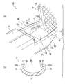
- FIG. 1A is a perspective view showing a first embodiment of a terminal-attached electric wire according to the present invention
- FIG. 1B is a cross-sectional view taken along the line AA in FIG.
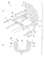
- FIG. 2 is a perspective view of the terminal in FIG. 3A is an enlarged perspective view of a portion indicated by an arrow B in FIG. 2
- FIG. 4 (b) is a cross-sectional view taken along line EE in FIG. 4 (a).
- FIG. 1A is a perspective view showing a first embodiment of a terminal-attached electric wire according to the present invention
- FIG. 1B is a cross-sectional view taken along the line AA in FIG.
- FIG. 2 is a perspective view of the terminal in FIG. 3A is an enlarged perspective view of a portion indicated by
- FIG. 5A is an enlarged perspective view of a terminal in Example 3 of the electric wire with terminal according to the present invention
- FIG. 5B is a cross-sectional view taken along the line FF in FIG. 6A is an enlarged perspective view of a terminal in Example 4 of the electric wire with terminal according to the present invention
- FIG. 6B is a cross-sectional view taken along the line GG in FIG. 6A
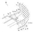
- FIG. 7A is an enlarged perspective view of a terminal in Example 5 of the electric wire with terminal according to the present invention
- FIG. 8B is a cross-sectional view taken along the line II in FIG. 8A.
- FIG. 9 is an enlarged perspective view of a terminal in Example 7 of the electric wire with terminal according to the present invention.
- FIG. 10 (a) is a perspective view showing a seventh embodiment of the electric wire with terminal according to the present invention
- FIG. 10 (b) is a cross-sectional view taken along the line JJ in FIG. 10 (a).
- FIG. 11 is an expansion perspective view which shows the modification of the terminal in Example 7 of the electric wire with a terminal which concerns on this invention.
- FIG. 12 is an enlarged perspective view showing another modification of the terminal in Example 7 of the electric wire with terminal according to the present invention.
- FIG. 13 is an enlarged perspective view of a terminal in Example 8 of the electric wire with terminal according to the present invention.
- FIG. 14 is an enlarged perspective view showing a modification of the terminal in the eighth embodiment of the electric wire with terminal according to the present invention.
- FIG. 15 is an enlarged perspective view of the terminal in Example 9 of the electric wire with terminal according to the present invention.
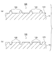
- 16A is a partial cross-sectional view of the terminal when the bottom wall is provided with the convex portion in FIG. 15, and FIG. 16B is the terminal when the concave portion is provided on the bottom wall in FIG. FIG.
- FIG. 1 (a) to FIG. 3 (b) show Example 1 of the electric wire with terminal according to the present invention.
- 1A is a perspective view showing Example 1 of a terminal-attached electric wire according to the present invention
- FIG. 1B is a cross-sectional view taken along line AA in FIG. 1A
- FIG. 3A is a perspective view of a terminal
- FIG. 3A is an enlarged perspective view of a portion indicated by an arrow B in FIG. 2
- FIG. 3B is a cross-sectional view taken along the line DD in FIG. is there.
- the terminal-attached electric wire 1 includes an electric wire 2, a terminal 3, and a resin portion 4.
- an electric wire 2 As shown in FIGS. 1A and 1B, the terminal-attached electric wire 1 according to the first embodiment includes an electric wire 2, a terminal 3, and a resin portion 4.
- each said structure of the electric wire 1 with a terminal is demonstrated.
- the electric wire 2 includes a conductor (not shown) and an insulating coating 5 that is coated on the conductor.
- the conductor is manufactured by twisting aluminum core wires.
- the terminal 3 is formed by pressing a copper plate.
- the terminal 3 in the first embodiment is a male terminal that is press-fitted into a connector housing (not shown) (assumed to be an example).
- the terminal 3 includes a terminal connection part 6, a cylinder part 7, a first connection part 8 a, a second connection part 8 b, and a wire connection part 9.
- the side where the terminal connection portion 6 is provided is defined as the front end side
- the side where the wire connection portion 9 is provided is defined as the rear end side.
- the terminal connection portion 6 is formed in a long and straight shape.
- the terminal connection part 6 is formed as a part connected to a female terminal (not shown) as a counterpart.
- the cylindrical portion 7 is provided on the rear end side of the terminal connecting portion 6 and is formed in a substantially box shape according to the shape of a terminal accommodating chamber (not shown) formed in the connector housing.
- the 1st connection part 8a is provided as a part with which the terminal connection part 6 and the cylinder part 7 are connected.
- the 1st connection part 8a is formed so that a width
- the electric wire connection part 9 is provided in the rear end side of the cylinder part 7, and is provided in order that the electric wire 2 and the terminal 3 may be electrically connected.
- the electric wire connection portion 9 includes a pair of first caulking portions 12 and a pair of second caulking portions 13.
- the pair of first caulking portions 12 is provided on the distal end side of the wire connecting portion 9.
- the pair of first caulking portions 12 are formed in a band plate shape.
- the pair of first caulking portions 12 are formed so that both side ends are raised toward the upper side of the terminal 3 and curved.
- a pair of 1st crimping part 12 is provided as a part by which the conductor of the electric wire 2 is crimped
- the pair of second caulking portions 13 are provided on the rear end side of the wire connecting portion 9.
- a pair of 2nd crimping part 13 is formed in strip
- the pair of second caulking portions 13 are formed so that both side ends are raised toward the upper side of the terminal 3 and curved.
- the pair of second caulking portions 13 is provided as a portion where the portion covered with the insulating coating 5 of the electric wire 2 is crimped by caulking.
- the second connecting portion 8b is provided as a portion where the cylindrical portion 7 and the wire connecting portion 9 are connected.
- the second connecting portion 8 b includes a bottom wall 14 and a pair of side walls 15 erected from both side ends of the bottom wall 14.
- the bottom wall 14 and the pair of side walls 15 are formed continuously with the cylindrical portion 7 and the wire connecting portion 9.
- the pair of side walls 15 includes a pair of parallel side walls 15a and a pair of inclined side walls 15b.
- the pair of parallel side walls 15 a is formed in a strip shape continuously to the rear end of the cylindrical portion 7. And a pair of parallel side wall 15a is opposingly arranged so that it may become parallel at predetermined intervals.
- the pair of inclined side walls 15b is formed continuously to the rear ends of the pair of parallel side walls 15a and is formed in a strip shape continuously to the tip of the wire connecting portion 9. And a pair of inclination side wall 15b is formed so that a space
- the pair of inclined side walls 15b has a groove portion (peeling prevention portion) 16 formed on the inner surface 17 thereof.
- the groove 16 is formed to have a predetermined depth from the inner surface 17 of the pair of inclined side walls 15b.
- the groove 16 has a concave cross section.
- the groove 16 has an elongated rectangular opening.
- the groove 16 has a direction intersecting with the mold release direction indicated by an arrow C (that is, a direction extending from the front to the back of the paper surface in FIG. 1B).
- the width is formed to be longer than the width in the mold release direction.
- the resin portion 4 is a conductor exposed portion (not shown) at the connection point between the conductor of the electric wire 2 and the terminal 3 in a state where the electric wire 2 and the terminal 3 are connected. 2), and is provided to prevent electrolytic corrosion that occurs when water enters the connection portion between the conductor and the terminal 3.
- the resin portion 4 is formed so as to cover a range from the pair of inclined side walls 15b of the second connecting portion 8b to the terminal portion of the electric wire 2. Furthermore, the resin part 4 completely covers the outer periphery in a range from the pair of inclined side walls 15b of the second connecting part 8b in the terminal-attached electric wire 1 to the terminal part of the electric wire 2.
- the resin portion 4 is formed also inside the groove portion 16 because it is formed so as to cover the pair of inclined side walls 15b of the second connecting portion 8b. That is, the resin part 4 formed inside the groove part 16 is in a state of being caught by the terminal 3.
- the resin portion 4 is formed so as to enter the groove portion 16 of the terminal 3, so that the resin portion 4 is caught in the groove portion 16. Thereafter, when the upper mold in the mold is detached from the lower mold in the direction of arrow C in FIG. 1B, an external force is applied to the resin portion 4 in the direction in which the upper mold (mold) is detached. Therefore, the resin part 4 tries to peel from the terminal 3 in the direction of arrow C. Here, since the resin part 4 is caught in the groove part 16, the groove part 16 resists the resin part 4 to be peeled from the terminal 3 when an external force is applied.
- the groove 16 is formed in a direction crossing the direction of detachment of the upper mold (mold) indicated by arrow C in FIG. 1 (b).
- the width is longer than the width of the upper mold (mold) in the direction of separation.
- the groove 16 is provided with a groove so that the width of the upper mold (mold) in the separation direction is longer than the width in the direction intersecting the separation direction of the upper mold (mold).
- die) is wide. Therefore, the groove portion 16 can sufficiently resist the resin portion 4 that is to be peeled off from the terminal 3 in the direction in which the upper die (die) is detached.
- the groove portion 16 which is the separation preventing portion resists the resin portion 4 to be separated from the terminal 3 when an external force is applied. Therefore, it is possible to provide the terminal-attached electric wire 1 in which the resin portion 4 is prevented from peeling from the terminal 3.
- the resin portion 4 is caught in the groove portion 16, so that the resin portion 4 does not peel from the terminal 3 even if an external force is applied to the resin portion 4.
- the groove 16 is provided so as to be long with respect to the width of the upper mold (mold) in the detaching direction in the direction intersecting with the upper mold (mold) detaching direction, It is possible to sufficiently resist the resin portion 4 that is about to be peeled off from the terminal 3 in the direction in which the mold (mold) is detached. Therefore, it is possible to provide the terminal-attached electric wire 1 in which the resin portion 4 is prevented from peeling off from the terminal 3 more reliably.
- the electric wire with terminal according to the present invention may use any of the following Examples 2 to 4 in addition to the above Example 1.
- the protrusion part (peeling prevention part) 21 is provided in a pair of inclination side wall 15b of the terminal 20 in Example 2.
- the projecting portion 21 has a convex cross section.
- the protruding portion 21 is formed to protrude from the inner surface 17 of the pair of inclined side walls 15b so as to face each other.
- the protrusion 21 has a width in a direction that intersects the direction in which the upper mold (mold) is detached (the direction of the arrow C in FIG. 1B) is the width in the direction in which the upper mold (mold) is detached. It is formed to be longer than the length.
- the pair of inclined side walls 15b of the terminal 30 in Example 3 are formed with an opening 32 penetrating in a rectangular shape (the shape is not limited to a rectangular shape).
- Protruding portions (peeling prevention portions) 31 are formed at both ends of the opening portion 32.
- the protrusion 31 is formed in an arch shape so as to cover the opening 32.
- the protrusions 31 are formed to protrude from the inner surface 17 of the inclined side wall 15b so as to face each other.
- the protrusion 31 has a width in a direction that intersects with the direction in which the upper mold (mold) is detached (the direction of the arrow C in FIG. 1B) is the width in the direction in which the upper mold (mold) is detached. It is formed to be longer than the length.
- the pair of inclined side walls 15b of the terminal 40 has an opening 42 penetrating in a triangular shape (the shape is not limited to a triangular shape).
- a protruding portion (peeling prevention portion) 41 is formed at one end of the opening 42.
- the protrusion 41 is formed in a substantially fan shape so as to cover the opening 42.
- the protruding portion 41 is formed to protrude from the inner surface 17 of the inclined side wall 15b so as to face each other.
- the protrusion 41 has a width in a direction that intersects the direction in which the upper mold (mold) is detached (the direction of the arrow C in FIG. 1B) is the width in the direction in which the upper mold (mold) is detached. It is formed to be longer than the length.
- the resin portion 4 is formed as if the protruding portion 21 is sandwiched. Further, according to the terminals 30 and 40 in Examples 3 and 4, when the resin portion 4 is formed, the resin enters the openings 32 and 42, and the resin portion 4 is formed in the openings 32 and 42. Thereby, the protrusions 31 and 41 lock the resin portion 4. From this, when the resin part 4 is formed, the resin part 4 is caught by the protruding parts 21, 31, 41. By doing so, even if an external force is applied to the resin part 4, the resin part 4 does not peel from the terminals 20, 30, 40.
- the projecting portions 21, 31, and 41 are provided so as to be longer than the width of the upper mold (mold) in the direction of detachment in the direction intersecting with the direction of detachment of the upper mold (mold). ing. Then, the protrusions 21, 31, and 41 have a longer length in the separation direction of the upper mold (mold) than the width in the direction intersecting the separation direction of the upper mold (mold). Compared with the case where the protrusion is provided on the upper portion, the portion on which the resin portion 4 to be peeled in the direction of detachment of the upper mold (mold) is hooked is wider. Therefore, the protrusions 21, 31, and 41 can sufficiently resist the resin portion 4 that is about to be peeled in the direction in which the upper mold (mold) is detached.
- the same effect as that of the electric wire with terminals 1 of Example 1 can be obtained.
- the resin portion 4 will not peel from the terminals 20, 30, 40 even if an external force is applied to the resin portion 4.
- the projecting portions 21, 31, and 41 are provided so as to be longer than the width of the upper mold (mold) in the direction of detachment in the direction intersecting with the direction of detachment of the upper mold (mold). Therefore, it is possible to sufficiently resist the resin portion 4 that is about to be peeled in the direction in which the upper mold (mold) is detached. Therefore, it is possible to provide a terminal-attached electric wire in which the resin portion 4 is prevented from being peeled off from the terminals 20, 30, 40 more reliably.
- Example 5 For the electric wire with terminal according to the present invention, the following Example 5 may be used in addition to the above Examples 1 to 4.
- the tips of the pair of inclined side walls 15b of the terminal 50 in the fifth embodiment are formed to protrude with a predetermined length from the tips of the pair of parallel side walls 15a.
- the tip ends of the pair of inclined side walls 15 b are bent inward to form a bent portion (peeling prevention portion) 51.
- the bent portion 51 is formed such that the length of the terminal 50 in the longitudinal direction is longer than the width in the direction orthogonal to the longitudinal direction of the terminal 50 (in this way, the bent portion 51 is By forming, the part which hooks the resin part 4 in (a), (b) of FIG. 1 can be increased.
- the resin portion 4 when the resin portion 4 is formed, the resin portion 4 is also formed below the bent portion 51. If it does so, the resin part 4 will be caught in the bending part 51. FIG. Therefore, even if an external force is applied to the resin portion 4, the resin portion 4 does not peel from the terminal 50.
- the bent portion 51 is provided as if it covers the resin portion 4 formed inside the terminal 50. If it does so, it will become a part where the resin part 4 which is going to peel from the terminal 50 in the removal direction of an upper mold
- the same effect as that of the terminal 3 in the first embodiment is obtained, and in particular, the resin portion 4 is caught by the bent portion 51. Even if an external force is applied, the resin portion 4 does not peel from the terminal 50. Moreover, since the bending part 51 is provided so that the resin part 4 which exists inside the terminal 50 may be covered, it is in the resin part 4 which is going to peel from the terminal 50 in the removal direction of an upper mold (mold). It can resist sufficiently. Therefore, it is possible to provide the terminal-attached electric wire in which the resin portion 4 is prevented from being peeled off from the terminal 50 more reliably.
- Example 6 For the electric wire with terminal according to the present invention, the following Example 6 may be used in addition to the above Examples 1 to 5.
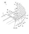
- an opening (peeling prevention portion) 61 is formed through the pair of inclined side walls 15 b of the terminal 60 in the sixth embodiment.
- the opening 61 is formed in a perfect circle shape, but may be formed in an oval shape (the shape is an example).
- the shape is not limited to a circular shape, and may be formed in a polygonal shape such as a triangular shape, a square shape, or a rectangular shape.
- the length of the width in the direction (the direction of the arrow C in FIG. 1B) intersecting the separation direction of the upper mold (mold). Is formed so as to be longer than the length of the width of the upper mold (mold) in the separation direction.
- the resin when the resin portion 4 is formed, the resin enters the opening 61, and the resin portion 4 is formed in the opening 61. If it does so, the resin part 4 will be hooked in the opening part 61. FIG. Therefore, even if an external force is applied to the resin part 4, the resin part 4 does not peel from the terminal 60.
- the opening part 61 is provided in the inclination side wall 15b erected along the removal direction of the upper mold (mold). Therefore, the opening 61 can sufficiently resist the resin portion 4 that is to be peeled off from the terminal 60 in the direction in which the upper mold (mold) is detached.
- a peeling prevention part can be provided only by penetrating and forming the opening part 61 in the inclined side wall 15b.
- the same effect as the terminal 3 in the first embodiment is obtained, and in particular, the resin portion 4 is caught in the opening 61. Even when an external force is applied, the resin portion 4 does not peel from the terminal 60.
- the opening 61 is provided on the inclined side wall 15b erected along the removal direction of the upper mold (mold), the opening 61 is to be peeled from the terminal 60 in the removal direction of the upper mold (mold). It is possible to sufficiently resist the resin part 4 to be performed. Therefore, it is possible to provide a terminal-attached electric wire in which the resin portion 4 is prevented from peeling off from the terminal 60 more reliably.
- the peeling preventing portion can be provided simply by penetrating the opening 61 in the inclined side wall 15b, in addition to the above effects, the peeling preventing portion can be simply provided. it can.
- Example 7 The terminal-attached electric wire according to the present invention may use the following Example 7 in addition to the above Examples 1-6.
- an opening (peeling prevention portion) 71 is formed through the substantially central portion of the bottom wall 14 of the terminal 70 in the seventh embodiment.
- the opening 71 is formed in a perfect circle shape, it may be formed in a square shape like the opening (peeling prevention portion) 81 formed through the bottom wall 14 of the terminal 80 in FIG. (It is not limited to these shapes. For example, it may be formed in other polygonal shapes such as a triangle).
- the opening portion 71 is formed in the vicinity of a portion where the bottom wall 14 and the side wall 15 are continuous. Also good.
- the opening part 91b is penetratingly formed in the vicinity of the part where the bottom wall 14 and the side wall 15 on the opposite side to the position where the opening part 91a is formed are continuous.
- the opening 91 is formed in a rectangular shape (the shape is not limited to a rectangular shape. In addition, for example, an oval shape may be used).
- the electric wire 200 with a terminal is the structure same as the electric wire 1 with a terminal in FIG. 1 except the point provided with the terminal 70 in FIG. Therefore, description of other structures is omitted.
- the electric wire 200 with a terminal provided with the terminal 70 is demonstrated here, you may use the electric wire with a terminal provided with the terminal 80 in FIG. 11, and the terminal 90 in FIG.
- the resin portion 4 when the resin portion 4 is molded, the resin portion 4 is formed by entering into the opening 71 as shown in FIG. 10 (b).
- the outer wall 72 of the bottom wall 14 is also covered.
- the resin part 4 should just cover a part in the opening part 71. FIG. That is, it is not necessary to cover the entire opening 71.
- the resin portion 4 covers the inner surface 73 of the bottom wall 14, is formed by entering the opening 71, and further covers the outer surface 72 of the bottom wall 14. Therefore, the resin part 4 covering the inner surface 73 of the bottom wall 14 and the resin part 4 covering the outer surface 72 of the bottom wall 14 are formed as if to sandwich the bottom wall 14. That is, the resin part 4 is caught on the bottom wall 14.
- the resin part 4 After the resin part 4 is molded, when the upper mold (mold) is separated in the direction of arrow K in FIG. 10B, the upper mold (mold) is detached from the resin part 4. External force works. Therefore, the resin part 4 tries to peel from the terminal 70 in the direction of the arrow K.
- the resin portion 4 is formed so as to sandwich the bottom wall 14 of the terminal 70 and is in a state of being caught by the bottom wall 14. Therefore, the resin part 4 does not peel from the terminal 70 even if an external force is applied to the resin part 4 by the resin part 4 being caught on the bottom wall 14. Further, since the resin part 4 is caught on the bottom wall 14 to prevent the resin part 4 from being peeled off, it is not necessary to cover the entire opening 71 with the resin part 4.
- the resin portion 4 covers the inner surface 73 (83, 93) of the bottom wall 14 and is in the opening 71 (81, 91).
- the outer surface 72 (82, 92) of the bottom wall 14 is covered. Therefore, the resin portion 4 that covers the inner surface 73 (83, 93) of the bottom wall 14 and the resin portion 4 that covers the outer surface 72 (82, 92) of the bottom wall 14 are formed so as to sandwich the bottom wall 14. The portion 4 is caught on the bottom wall 14. For this reason, even if an external force is applied to the resin part 4, it does not peel off from the terminal 70 (80, 90).
- the terminal-attached electric wire 200 in which the resin portion 4 is prevented from peeling from the terminal 70 (80, 90) more reliably.
- the peeling prevention part can be provided only by forming the opening 71 (81, 91) through the bottom wall 14, in addition to the above effects, The peeling prevention part can be easily provided.
- Example 8 For the electric wire with terminal according to the present invention, the following Example 8 may be used in addition to the above Examples 1-7.
- an opening (peeling prevention portion) 101 is formed through the substantially central portion of the bottom wall 14 of the terminal 100 in the eighth embodiment.
- the opening 101 is formed in a rectangular shape orthogonal to the longitudinal direction of the terminal 100 (the shape is not limited to a rectangular shape).
- a locking portion 104 is provided on the bottom wall 14 so as to cover the upper surface of the opening 101 perpendicular to the longitudinal direction of the terminal 100.
- the locking portion 104 is formed so as to protrude from the inner surface 103 of the bottom wall 14, and is formed in a substantially arc-shaped arch shape so as to connect both ends of the opening 101 (the shape is an example). In addition, as described later, it may be formed in an arch shape other than a substantially arc shape).
- a hole 105 is formed between the upper surface of the opening 101 and the lower side of the locking portion 104. The hole 105 communicates with the opening 101.
- the locking portion 114 is formed so as to protrude from the inner surface 113 of the bottom wall 14, and has a substantially square bracket shape so as to connect both ends of the opening (peeling prevention portion) 111. It may be formed in an arch shape.
- a hole 115 is formed between the upper surface of the opening 111 and the lower side of the locking portion 114.
- the resin when the resin portion 4 is formed, the resin enters from the holes 105 and 115 and the resin enters the openings 101 and 111. By doing so, the resin part 4 is formed in the openings 101 and 111. Accordingly, the locking portions 104 and 114 formed so as to cover the upper surfaces of the openings 101 and 111 lock the resin portion 4. That is, the resin part 4 is caught on the bottom wall 14 even if the resin part 4 does not cover the outer surfaces 102 and 112 of the bottom wall 14 as in the seventh embodiment. Therefore, even when an external force is applied to the resin portion 4, the locking portions 104 and 114 lock the resin portion 4, so that the resin portion 4 does not peel from the terminals 100 and 110.
- the terminals 100 and 110 in the eighth embodiment when the resin portion 4 is formed in the openings 101 and 111, the locking portions 104 and 114 lock the resin portion 4.
- the terminals 100 and 110 are not peeled off. Therefore, it is possible to provide a terminal-attached electric wire in which the resin portion 4 is prevented from being peeled off from the terminals 100 and 110 more reliably.
- Example 9 The terminal-attached electric wire according to the present invention may use the following Example 9 in addition to the above Examples 1-8.
- the terminal 120 has the same configuration as the terminal 3 in FIG. 3 except that a convex portion 124 or a concave portion 125 is formed on the inner surface 123 of the bottom wall 14.
- the convex portion 124 or the concave portion 125 is formed in a lattice shape on the inner surface 123 of the bottom wall 14.
- FIG. 16A and 16B are partial cross-sectional views of a portion surrounded by a broken line L in FIG.
- FIG. 16A shows a case where a convex portion 124 is formed on the inner surface 123 of the bottom wall 14.
- the convex portions 124 are formed on the inner surface 123 of the bottom wall 14 with a predetermined interval.
- the convex part 124 is protrudingly provided so that the cross-sectional shape may protrude upward.
- FIG. 16B shows a case where the concave portion 125 is formed on the inner surface 123 of the bottom wall 14.
- the concave portion 125 is formed on the inner surface 123 of the bottom wall 14 with a predetermined interval.
- the concave portion 125 is formed as a groove having a substantially square bracket shape in cross section (the shape is not limited to this. For example, even if the cross sectional shape is formed in a substantially U shape) Be good).
- a protrusion 21 in FIG. 4 may be provided on the inner surface 17 of the pair of inclined side walls 15 b of the terminal 120 instead of the groove 16. Further, the protrusion 31 in FIG. 5 may be provided. Furthermore, the protrusion 41 in FIG. 6 may be provided. In addition, as shown in FIG. 7, the front ends of the pair of inclined side walls 15b may be bent inward to form a bent portion 51. Further, as shown in FIG. 8, an opening 61 may be formed through the pair of inclined side walls 15b.
- the resin portion 4 covers the inner surface 123 of the bottom wall 14 on which the convex portion 124 or the concave portion 125 is formed, thereby closely contacting the resin portion 4 on the bottom wall 14. Increases area. Then, in addition to the resin part 4 being caught in the groove part 16 or the projecting parts 21, 31, 41 (others, the bent part 51 and the opening part 61), the area of the bottom wall 14 in close contact with the resin part 4 is increased. The adhesion of the resin part 4 to the terminal 120 is improved. Therefore, even if an external force is applied to the resin part 4, it is possible to sufficiently suppress the resin part 4 from peeling from the terminal 120.
- the area of the bottom wall 14 that is in close contact with the resin portion 4 is increased, whereby the adhesion of the resin portion 4 to the terminal 120 is improved and the resin portion 4 is improved. Even when an external force is applied, it is possible to sufficiently suppress the resin portion 4 from peeling from the terminal 120. Therefore, it is possible to provide the terminal-attached electric wire in which the resin portion 4 is prevented from being peeled off from the terminal 120 more reliably.
- the resin part (4) covering the exposed conductor part of the terminal (3, 20, 30, 40, 50, 60, 70, 80, 90, 100, 110, 120) to which the conductor is connected is molded.
- An electric wire with a terminal (1,200) At least a portion of the resin portion (4) is covered with the resin portion (4) in the terminal (3, 20, 30, 40, 50, 60, 70, 80, 90, 100, 110, 120).
- the resin part (4) is peeled from the terminals (3, 20, 30, 40, 50, 60, 70, 80, 90, 100, 110, 120) in the mold release direction.
- Detachment prevention part (groove part 16, protrusion part 21, 31, 41, bending part 51, opening part 61, 71, 81, 91, 101, 111) provided in order to prevent the electric wire with a terminal (1,200) .
- the electric wire with terminal (1,200) according to the above [1]
- the terminal (where the groove portion 16, the protruding portions 21, 31, 41, the bent portion 51, the opening portions 61, 71, 81, 91, 101, 111) are covered with the resin portion (4) ( 3, 20, 30, 40, 50, 60, 70, 80, 90, 100, 110, 120) with terminal (1, 200) provided on the side wall (15) or bottom wall (14).
- the said peeling prevention part (51) is an electric wire with a terminal (1) which is a bending part (51) formed by bending the front-end
- the electric wire with a terminal of the present invention it is possible to prevent the resin part from being peeled from the terminal when an external force is applied to the resin part.
- it is useful for preventing the resin part from being peeled from the terminal in the mold release direction when the mold is detached from the electric wire with terminal after the resin part is molded.
Landscapes
- Connections Effected By Soldering, Adhesion, Or Permanent Deformation (AREA)
- Connector Housings Or Holding Contact Members (AREA)
Abstract
Description
(1) 導体が接続される端子の導体露出部を覆う樹脂部が金型成形される端子付き電線であって、前記端子における前記樹脂部に覆われる箇所には、少なくとも、前記樹脂部が金型成形された後、前記樹脂部が金型の離脱方向に前記端子から剥離するのを防止するための剥離防止部が設けられる端子付き電線。
また、上記(5)の構成によれば、側壁に開口部を貫通形成するだけで剥離防止部を設けることができる。
また、上記(6)の構成によれば、底壁に開口部を貫通形成するだけで剥離防止部を設けることができる。
また、上記(5)に記載された端子付き電線によれば、側壁に開口部を貫通形成するだけで剥離防止部を設けることができるため、上記効果の他、剥離防止部を簡単に設けることができるという効果を奏する。
また、上記(6)に記載された端子付き電線によれば、底壁に開口部を貫通形成するだけで剥離防止部を設けることができるため、上記効果の他、剥離防止部を簡単に設けることができるという効果を奏する。
図1の(a)~図3の(b)には、本発明に係る端子付き電線の実施例1が示されている。
図1の(a)は本発明に係る端子付き電線の実施例1を示す斜視図、図1の(b)は図1の(a)におけるA-A間断面図、図2は図1の(a)における端子の斜視図、図3の(a)は図2における矢印Bが示す部分の拡大斜視図、図3の(b)は図3の(a)におけるD-D間断面図である。
まず、電線2が端子3の電線接続部9に電気的に接続された後、上下型からなる金型(図示せず)に端子3がセットされ、金型内のキャビティに樹脂が注入される。そうすると、図1の(a),(b)に示すように、一対の傾斜側壁15bから電線2の端末部までの外周が樹脂によって完全に覆われる。すなわち、導体と端子3との接続部分における導体露出部が樹脂によって覆われる。また、図1の(b)に示すように、第2連結部8bの内側に流入した樹脂は、溝部16の内側にも流入する。すなわち、溝部16の内部は、樹脂に満たされることになる。そして、この樹脂が固化することによって樹脂部4が形成され、図1の(a)に示す本実施例1の端子付き電線1が完成する。
本発明に係る端子付き電線は、上記実施例1の他、下記の実施例2~4の何れを用いても良いものとする。
図4の(a)に示すように、実施例2における端子20の一対の傾斜側壁15bには、突出部(剥離防止部)21が設けられている。図4の(b)に示すように、突出部21は、断面形状が凸状に形成されている。突出部21は、一対の傾斜側壁15bの内面17から互いに向かい合うように突出して形成されている。突出部21は、上型(金型)の離脱方向(図1の(b)における矢印Cの方向)に交差する方向の幅の長さが、上型(金型)の離脱方向の幅の長さよりも長寸となるように形成されている。
本発明に係る端子付き電線は、上記実施例1~4の他、下記の実施例5を用いても良いものとする。
図7に示すように、実施例5における端子50の一対の傾斜側壁15bの先端は、一対の平行側壁15aの先端よりも所定の長さで突出して形成されている。一対の傾斜側壁15bの先端は、内側に曲げられ、曲げ部(剥離防止部)51として形成されている。曲げ部51は、端子50の長手方向の幅の長さが、端子50の長手方向に直交する方向の幅の長さよりも長寸となるように形成されている(このように曲げ部51を形成することによって、図1の(a),(b)における樹脂部4を引っ掛ける部分を多くすることができる)。
本発明に係る端子付き電線は、上記実施例1~5の他、下記の実施例6を用いても良いものとする。
図8に示すように、実施例6における端子60の一対の傾斜側壁15bには、開口部(剥離防止部)61が貫通形成されている。開口部61は、真円形状に形成されているが、その他、長円形状に形成されても良いものとする(形状は一例であるものとする)。また、図示しないが、円形状に限定されることなく、三角形状、正方形状、長方形状等の多角形状に形成されても良いものとする。なお、長円形状、長方形状等長寸が存在する開口部61の場合、上型(金型)の離脱方向に交差する方向(図1の(b)における矢印Cの方向)の幅の長さが、上型(金型)の離脱方向の幅の長さよりも長寸となるように形成されるものとする。
また、実施例6における端子60によれば、傾斜側壁15bに開口部61を貫通形成するだけで剥離防止部を設けることができる。
また、実施例6のおける端子60によれば、傾斜側壁15bに開口部61を貫通形成するだけで剥離防止部を設けることができるため、上記効果の他、剥離防止部を簡単に設けることができる。
本発明に係る端子付き電線は、上記実施例1~6の他、下記の実施例7を用いても良いものとする。
図9に示すように、実施例7における端子70の底壁14の略中央部には、開口部(剥離防止部)71が貫通形成されている。なお、開口部71は、真円形状に形成されているが、図11における端子80の底壁14に貫通形成された開口部(剥離防止部)81のように、四角形状に形成されても良いものとする(これらの形状に限られるものではない。その他、例えば、三角形等の他の多角形状に形成されても良いものとする)。
図10の(a)に示すように、端子付き電線200は、図9における端子70を備える点以外は、図1における端子付き電線1と同一の構成である。したがって、他の構成の説明は省略する。なお、ここでは、端子70を備える端子付き電線200について説明するが、この他、図11における端子80や図12における端子90を備える端子付き電線を用いても良いものとする。
また、実施例7の端子70(80,90)によれば、底壁14に開口部71(81,91)を貫通形成するだけで剥離防止部を設けることができるため、上記効果の他、剥離防止部を簡単に設けることができる。
本発明に係る端子付き電線は、上記実施例1~7の他、下記の実施例8を用いても良いものとする。
図13に示すように、実施例8における端子100の底壁14の略中央部には、開口部(剥離防止部)101が貫通形成されている。開口部101は、端子100の長手方向に直交して、長方形状に形成されている(形状は長方形状に限られるものではない)。底壁14には、端子100の長手方向に直交して、開口部101の上面を覆うように係止部104が設けられている。係止部104は、底壁14の内面103から突出するように形成され、開口部101の両端を繋ぐように略円弧形のアーチ状に形成されている(形状は一例であるものとする。その他、後述するように略円弧形以外の形状のアーチ状に形成されていても良いものとする)。開口部101の上面と、係止部104の下側との間には、孔部105が形成されている。孔部105は、開口部101に連通されている。
本発明に係る端子付き電線は、上記実施例1~8の他、下記の実施例9を用いても良いものとする。
図15に示すように、端子120は、底壁14の内面123に凸状部124又は凹状部125が形成されている点以外は、図3における端子3と同じ構成である。凸状部124又は凹状部125は、底壁14の内面123に格子状に形成されている。
[1] 導体が接続される端子(3,20,30,40,50,60,70,80,90,100,110,120)の導体露出部を覆う樹脂部(4)が金型成形される端子付き電線(1,200)であって、
前記端子(3,20,30,40,50,60,70,80,90,100,110,120)における前記樹脂部(4)に覆われる箇所には、少なくとも、前記樹脂部(4)が金型成形された後、前記樹脂部(4)が金型の離脱方向に前記端子(3,20,30,40,50,60,70,80,90,100,110,120)から剥離するのを防止するための剥離防止部(溝部16、突出部21,31,41、曲げ部51、開口部61,71,81,91,101,111)が設けられる
端子付き電線(1,200)。
[2] 上記[1]に記載の端子付き電線(1,200)であって、
前記剥離防止部(溝部16、突出部21,31,41、曲げ部51、開口部61,71,81,91,101,111)が、前記樹脂部(4)に覆われる箇所における前記端子(3,20,30,40,50,60,70,80,90,100,110,120)の側壁(15)又は底壁(14)に設けられた
端子付き電線(1,200)。
[3] 上記[2]に記載の端子付き電線(1)であって、
前記剥離防止部(溝部16、突出部21,31,41)は、前記金型の離脱方向に交差する方向に、前記金型の離脱方向の幅の長さに対して長寸となるように溝部(16)又は突出部(21,31,41)が形成されたものである
端子付き電線(1)。
[4] 上記[2]に記載の端子付き電線(1)であって、
前記剥離防止部(51)は、前記側壁(15)の先端が内側に曲げられて形成される曲げ部(51)である
端子付き電線(1)。
[5] 上記[2]に記載の端子付き電線(1,200)であって、
前記剥離防止部(61,71,81,91)が、前記側壁(15)に貫通形成される開口部(61,71,81,91)である
端子付き電線(1,200)。
[6] 上記[2]に記載の端子付き電線(200)であって、
前記剥離防止部(71,81,91,101,111)は、前記底壁(14)に貫通形成される開口部(71,81,91,101,111)であり、
前記樹脂部(4)は、前記開口部(71,81,91,101,111)内に浸入して形成されるとともに、前記底壁(14)の外面(72,82,92,102,112)をも覆って形成されている
端子付き電線(200)。
[7] 上記[6]に記載の端子付き電線(200)であって、
前記開口部(101,111)の両端を繋ぐようにアーチ状に形成される係止部(104,114)が設けられた
端子付き電線(200)。
[8] 上記[3]、[4]又は[5]のいずれか1つに記載の端子付き電線(200)であって、
前記底壁(14)に格子状に凸状部(124)又は凹状部(125)が形成される
端子付き電線(200)。
また、本出願は、2013年11月13日出願の日本特許出願(特願2013-234727)に基づくものであり、その内容はここに参照として取り込まれる。
Claims (8)
- 導体が接続される端子の導体露出部を覆う樹脂部が金型成形される端子付き電線であって、
前記端子における前記樹脂部に覆われる箇所には、少なくとも、前記樹脂部が金型成形された後、前記樹脂部が金型の離脱方向に前記端子から剥離するのを防止するための剥離防止部が設けられる
端子付き電線。 - 請求項1に記載の端子付き電線であって、
前記剥離防止部が、前記樹脂部に覆われる箇所における前記端子の側壁又は底壁に設けられた
端子付き電線。 - 請求項2に記載の端子付き電線であって、
前記剥離防止部は、前記金型の離脱方向に交差する方向に、前記金型の離脱方向の幅の長さに対して長寸となるように溝部又は突出部が形成されたものである
端子付き電線。 - 請求項2に記載の端子付き電線であって、
前記剥離防止部は、前記側壁の先端が内側に曲げられて形成される曲げ部である
端子付き電線。 - 請求項2に記載の端子付き電線であって、
前記剥離防止部が、前記側壁に貫通形成される開口部である
端子付き電線。 - 請求項2に記載の端子付き電線であって、
前記剥離防止部は、前記底壁に貫通形成される開口部であり、
前記樹脂部は、前記開口部内に浸入して形成されるとともに、前記底壁の外面をも覆って形成されている
端子付き電線。 - 請求項6に記載の端子付き電線であって、
前記開口部の両端を繋ぐようにアーチ状に形成される係止部が設けられた
端子付き電線。 - 請求項3、4又は5のいずれか1項に記載の端子付き電線であって、
前記底壁に格子状に凸状部又は凹状部が形成される
端子付き電線。
Priority Applications (3)
| Application Number | Priority Date | Filing Date | Title |
|---|---|---|---|
| US15/030,215 US9647352B2 (en) | 2013-11-13 | 2014-10-17 | Electric wire with terminal |
| DE112014005177.2T DE112014005177B4 (de) | 2013-11-13 | 2014-10-17 | Elektrodraht mit Anschluss |
| CN201480062441.2A CN105723565A (zh) | 2013-11-13 | 2014-10-17 | 具有端子的电线 |
Applications Claiming Priority (2)
| Application Number | Priority Date | Filing Date | Title |
|---|---|---|---|
| JP2013-234727 | 2013-11-13 | ||
| JP2013234727A JP6749039B2 (ja) | 2013-11-13 | 2013-11-13 | 端子付き電線 |
Publications (1)
| Publication Number | Publication Date |
|---|---|
| WO2015072283A1 true WO2015072283A1 (ja) | 2015-05-21 |
Family
ID=53057225
Family Applications (1)
| Application Number | Title | Priority Date | Filing Date |
|---|---|---|---|
| PCT/JP2014/077737 Ceased WO2015072283A1 (ja) | 2013-11-13 | 2014-10-17 | 端子付き電線 |
Country Status (5)
| Country | Link |
|---|---|
| US (1) | US9647352B2 (ja) |
| JP (1) | JP6749039B2 (ja) |
| CN (1) | CN105723565A (ja) |
| DE (1) | DE112014005177B4 (ja) |
| WO (1) | WO2015072283A1 (ja) |
Families Citing this family (15)
| Publication number | Priority date | Publication date | Assignee | Title |
|---|---|---|---|---|
| JP6302390B2 (ja) * | 2014-10-03 | 2018-03-28 | 矢崎総業株式会社 | 端子付電線 |
| DE112015004916T5 (de) | 2014-10-31 | 2017-07-13 | Yazaki Corporation | Elektrisches Kabel mit Anschluss und Verfahren zum Herstellen desselben |
| JP6591271B2 (ja) * | 2015-12-02 | 2019-10-16 | 日本航空電子工業株式会社 | 端子及びハーネス |
| JP2017195137A (ja) * | 2016-04-22 | 2017-10-26 | 株式会社オートネットワーク技術研究所 | 端子付き被覆電線およびワイヤーハーネス |
| USD856280S1 (en) * | 2017-05-25 | 2019-08-13 | Panduit Corp. | Termination tool |
| JP6556787B2 (ja) * | 2017-06-09 | 2019-08-07 | 矢崎総業株式会社 | 端子付き電線および端子圧着装置 |
| USD846414S1 (en) * | 2017-06-28 | 2019-04-23 | Panduit Corp. | Fiber connector termination tool |
| JP6911727B2 (ja) * | 2017-11-22 | 2021-07-28 | オムロン株式会社 | コネクタ用端子およびコネクタ |
| JP6544412B2 (ja) * | 2017-11-22 | 2019-07-17 | オムロン株式会社 | コネクタ用端子およびコネクタ |
| JP6768742B2 (ja) * | 2018-06-04 | 2020-10-14 | 矢崎総業株式会社 | 端子付き電線および端子付き電線の製造方法 |
| JP2019212458A (ja) * | 2018-06-04 | 2019-12-12 | 矢崎総業株式会社 | 端子付き電線および端子付き電線の製造方法 |
| JP7103204B2 (ja) * | 2018-12-21 | 2022-07-20 | 株式会社オートネットワーク技術研究所 | コネクタ構造体 |
| JP6887211B2 (ja) * | 2019-03-05 | 2021-06-16 | 古河電気工業株式会社 | 端子および端子付き電線 |
| JP7339067B2 (ja) | 2019-08-22 | 2023-09-05 | 矢崎総業株式会社 | 端子付き電線、及び、端子金具 |
| JP7225166B2 (ja) * | 2020-07-22 | 2023-02-20 | 矢崎総業株式会社 | 電線の製造方法および電線製造装置 |
Citations (9)
| Publication number | Priority date | Publication date | Assignee | Title |
|---|---|---|---|---|
| JPH11260527A (ja) * | 1998-03-09 | 1999-09-24 | Japan Aviation Electronics Ind Ltd | モールドインコンタクト構成体、及びその製造方法 |
| JP2001162647A (ja) * | 1999-12-09 | 2001-06-19 | Yazaki Corp | 被覆電線端末接続部の防水処理装置 |
| JP2001167821A (ja) * | 1999-12-09 | 2001-06-22 | Yazaki Corp | 被覆電線の端末接続部およびその防水処理方法と装置 |
| JP2003217703A (ja) * | 2002-01-25 | 2003-07-31 | Fujikura Ltd | モールド端子 |
| JP2007227163A (ja) * | 2006-02-23 | 2007-09-06 | Auto Network Gijutsu Kenkyusho:Kk | インサート部品及びその製造方法 |
| WO2012023314A1 (ja) * | 2010-08-17 | 2012-02-23 | 住友電装株式会社 | 端子金具 |
| JP2012129178A (ja) * | 2010-11-26 | 2012-07-05 | Yazaki Corp | 電線と端子の接続構造およびその製造方法 |
| JP2013098161A (ja) * | 2011-11-07 | 2013-05-20 | Toyota Motor Corp | 接続部材、防水接続構造 |
| WO2014017614A1 (ja) * | 2012-07-25 | 2014-01-30 | 矢崎総業株式会社 | 端子付き電線及びそれを用いたワイヤーハーネス |
Family Cites Families (16)
| Publication number | Priority date | Publication date | Assignee | Title |
|---|---|---|---|---|
| US4029388A (en) * | 1976-04-02 | 1977-06-14 | Illinois Tool Works Inc. | Electrical terminal constructed to prevent insert molding flash |
| DE3410461A1 (de) | 1984-03-22 | 1985-09-26 | Stocko Metallwarenfabriken Henkels Und Sohn Gmbh & Co, 5600 Wuppertal | Steckerbuchse mit isolierstoffummantelung sowie vorrichtung fuer ihre herstellung |
| JP3040235B2 (ja) * | 1991-02-12 | 2000-05-15 | 松下電子工業株式会社 | リードフレームとそれを用いた樹脂封止型半導体装置 |
| US5108317A (en) * | 1991-03-21 | 1992-04-28 | Amp Incorporated | Sealed metal shell connector and method of molding a plastic insert within a metal shell |
| JPH0629021U (ja) * | 1992-09-21 | 1994-04-15 | アルプス電気株式会社 | 電気部品の端子取付構造 |
| US6206735B1 (en) * | 1998-08-28 | 2001-03-27 | Teka Interconnection Systems, Inc. | Press fit print circuit board connector |
| JP3613445B2 (ja) | 1999-05-18 | 2005-01-26 | 矢崎総業株式会社 | バッテリ接続プレート |
| EP1796216B1 (de) * | 2005-12-09 | 2008-04-23 | Delphi Technologies, Inc. | Kabelschuh |
| JP5311962B2 (ja) | 2008-10-24 | 2013-10-09 | 矢崎総業株式会社 | アルミ電線用圧着端子及びアルミ電線用圧着端子の製造方法 |
| JP2010108828A (ja) | 2008-10-31 | 2010-05-13 | Furukawa Electric Co Ltd:The | 導体と端子の接続部および接続方法 |
| JP2010108829A (ja) * | 2008-10-31 | 2010-05-13 | Furukawa Electric Co Ltd:The | 導体と端子の接続部および接続方法 |
| JP2011096451A (ja) | 2009-10-28 | 2011-05-12 | Yazaki Corp | 圧着端子 |
| JP4848040B2 (ja) * | 2010-04-08 | 2011-12-28 | 株式会社オートネットワーク技術研究所 | ワイヤーハーネスの端末構造 |
| JP5063750B2 (ja) * | 2010-07-23 | 2012-10-31 | 株式会社オートネットワーク技術研究所 | ワイヤーハーネスの端末構造 |
| WO2012018049A1 (ja) | 2010-08-06 | 2012-02-09 | 株式会社オートネットワーク技術研究所 | 端子付き電線、及びコネクタ |
| US8622774B2 (en) * | 2011-11-07 | 2014-01-07 | Delphi Technologies, Inc. | Electrical contact having channel with angled sidewalls and romboid knurl pattern |
-
2013
- 2013-11-13 JP JP2013234727A patent/JP6749039B2/ja active Active
-
2014
- 2014-10-17 DE DE112014005177.2T patent/DE112014005177B4/de active Active
- 2014-10-17 WO PCT/JP2014/077737 patent/WO2015072283A1/ja not_active Ceased
- 2014-10-17 CN CN201480062441.2A patent/CN105723565A/zh active Pending
- 2014-10-17 US US15/030,215 patent/US9647352B2/en not_active Expired - Fee Related
Patent Citations (9)
| Publication number | Priority date | Publication date | Assignee | Title |
|---|---|---|---|---|
| JPH11260527A (ja) * | 1998-03-09 | 1999-09-24 | Japan Aviation Electronics Ind Ltd | モールドインコンタクト構成体、及びその製造方法 |
| JP2001162647A (ja) * | 1999-12-09 | 2001-06-19 | Yazaki Corp | 被覆電線端末接続部の防水処理装置 |
| JP2001167821A (ja) * | 1999-12-09 | 2001-06-22 | Yazaki Corp | 被覆電線の端末接続部およびその防水処理方法と装置 |
| JP2003217703A (ja) * | 2002-01-25 | 2003-07-31 | Fujikura Ltd | モールド端子 |
| JP2007227163A (ja) * | 2006-02-23 | 2007-09-06 | Auto Network Gijutsu Kenkyusho:Kk | インサート部品及びその製造方法 |
| WO2012023314A1 (ja) * | 2010-08-17 | 2012-02-23 | 住友電装株式会社 | 端子金具 |
| JP2012129178A (ja) * | 2010-11-26 | 2012-07-05 | Yazaki Corp | 電線と端子の接続構造およびその製造方法 |
| JP2013098161A (ja) * | 2011-11-07 | 2013-05-20 | Toyota Motor Corp | 接続部材、防水接続構造 |
| WO2014017614A1 (ja) * | 2012-07-25 | 2014-01-30 | 矢崎総業株式会社 | 端子付き電線及びそれを用いたワイヤーハーネス |
Also Published As
| Publication number | Publication date |
|---|---|
| JP6749039B2 (ja) | 2020-09-02 |
| CN105723565A (zh) | 2016-06-29 |
| JP2015095388A (ja) | 2015-05-18 |
| US20160261054A1 (en) | 2016-09-08 |
| DE112014005177T5 (de) | 2016-07-21 |
| DE112014005177B4 (de) | 2023-11-30 |
| US9647352B2 (en) | 2017-05-09 |
Similar Documents
| Publication | Publication Date | Title |
|---|---|---|
| WO2015072283A1 (ja) | 端子付き電線 | |
| JP6601995B2 (ja) | 端子付き電線 | |
| CN103460509B (zh) | 具有菱形滚花图案的电接触件 | |
| JP5965751B2 (ja) | コネクタ端子及びコネクタ端子の止水方法 | |
| JP5737590B2 (ja) | 端子付き電線及び端子 | |
| KR101629125B1 (ko) | 단자 피팅 | |
| US9058919B2 (en) | Water proof press contact terminal and method for forming water proof press contact terminal | |
| CN103733447B (zh) | 防水连接器及其制造方法 | |
| CN103959560A (zh) | 中继端子 | |
| JP2013093261A (ja) | 電線端末接続構造及び中間キャップ | |
| JP2012221836A (ja) | 基板用コネクタ | |
| JP2007529093A (ja) | ソーラーパネルの電気的な接続のための差込接続器 | |
| WO2016143466A1 (ja) | 端子付き電線及び端子 | |
| CN109149187B (zh) | 连接器 | |
| JP5054798B2 (ja) | プラグキャップ及びその製造方法 | |
| JP5333299B2 (ja) | コネクタ | |
| JP6302390B2 (ja) | 端子付電線 | |
| JP6499409B2 (ja) | 電源分岐構造 | |
| JP5229583B2 (ja) | 機器用コネクタ | |
| JP5412142B2 (ja) | 圧着端子 | |
| JP2010021016A (ja) | 端子金具及び端子付き電線 | |
| JP5998188B2 (ja) | 端子付き電線及びその製造方法 | |
| JP5922485B2 (ja) | ヒューズユニット | |
| JP2013251181A (ja) | 端子金具 | |
| JP2009151966A (ja) | 端子金具 |
Legal Events
| Date | Code | Title | Description |
|---|---|---|---|
| 121 | Ep: the epo has been informed by wipo that ep was designated in this application |
Ref document number: 14861354 Country of ref document: EP Kind code of ref document: A1 |
|
| WWE | Wipo information: entry into national phase |
Ref document number: 15030215 Country of ref document: US |
|
| WWE | Wipo information: entry into national phase |
Ref document number: 1120140051772 Country of ref document: DE Ref document number: 112014005177 Country of ref document: DE |
|
| 122 | Ep: pct application non-entry in european phase |
Ref document number: 14861354 Country of ref document: EP Kind code of ref document: A1 |