WO2015037600A1 - 乗物用シート装置 - Google Patents
乗物用シート装置 Download PDFInfo
- Publication number
- WO2015037600A1 WO2015037600A1 PCT/JP2014/073873 JP2014073873W WO2015037600A1 WO 2015037600 A1 WO2015037600 A1 WO 2015037600A1 JP 2014073873 W JP2014073873 W JP 2014073873W WO 2015037600 A1 WO2015037600 A1 WO 2015037600A1
- Authority
- WO
- WIPO (PCT)
- Prior art keywords
- lateral acceleration
- seat
- steering speed
- vehicle
- acceleration
- Prior art date
- Legal status (The legal status is an assumption and is not a legal conclusion. Google has not performed a legal analysis and makes no representation as to the accuracy of the status listed.)
- Ceased
Links
Images


Classifications
-
- B—PERFORMING OPERATIONS; TRANSPORTING
- B60—VEHICLES IN GENERAL
- B60N—SEATS SPECIALLY ADAPTED FOR VEHICLES; VEHICLE PASSENGER ACCOMMODATION NOT OTHERWISE PROVIDED FOR
- B60N2/00—Seats specially adapted for vehicles; Arrangement or mounting of seats in vehicles
- B60N2/02—Seats specially adapted for vehicles; Arrangement or mounting of seats in vehicles the seat or part thereof being movable, e.g. adjustable
- B60N2/0224—Non-manual adjustments, e.g. with electrical operation
- B60N2/0244—Non-manual adjustments, e.g. with electrical operation with logic circuits
- B60N2/0268—Non-manual adjustments, e.g. with electrical operation with logic circuits using sensors or detectors for adapting the seat or seat part, e.g. to the position of an occupant
-
- B—PERFORMING OPERATIONS; TRANSPORTING
- B60—VEHICLES IN GENERAL
- B60N—SEATS SPECIALLY ADAPTED FOR VEHICLES; VEHICLE PASSENGER ACCOMMODATION NOT OTHERWISE PROVIDED FOR
- B60N2/00—Seats specially adapted for vehicles; Arrangement or mounting of seats in vehicles
- B60N2/02—Seats specially adapted for vehicles; Arrangement or mounting of seats in vehicles the seat or part thereof being movable, e.g. adjustable
- B60N2/04—Seats specially adapted for vehicles; Arrangement or mounting of seats in vehicles the seat or part thereof being movable, e.g. adjustable the whole seat being movable
- B60N2/14—Seats specially adapted for vehicles; Arrangement or mounting of seats in vehicles the seat or part thereof being movable, e.g. adjustable the whole seat being movable rotatable, e.g. to permit easy access
-
- B—PERFORMING OPERATIONS; TRANSPORTING
- B60—VEHICLES IN GENERAL
- B60N—SEATS SPECIALLY ADAPTED FOR VEHICLES; VEHICLE PASSENGER ACCOMMODATION NOT OTHERWISE PROVIDED FOR
- B60N2/00—Seats specially adapted for vehicles; Arrangement or mounting of seats in vehicles
- B60N2/02—Seats specially adapted for vehicles; Arrangement or mounting of seats in vehicles the seat or part thereof being movable, e.g. adjustable
- B60N2/0224—Non-manual adjustments, e.g. with electrical operation
- B60N2/0244—Non-manual adjustments, e.g. with electrical operation with logic circuits
- B60N2/0277—Non-manual adjustments, e.g. with electrical operation with logic circuits characterised by the calculation method or calculation flow chart of sensor data for adjusting the seat
-
- B—PERFORMING OPERATIONS; TRANSPORTING
- B60—VEHICLES IN GENERAL
- B60N—SEATS SPECIALLY ADAPTED FOR VEHICLES; VEHICLE PASSENGER ACCOMMODATION NOT OTHERWISE PROVIDED FOR
- B60N2/00—Seats specially adapted for vehicles; Arrangement or mounting of seats in vehicles
- B60N2/02—Seats specially adapted for vehicles; Arrangement or mounting of seats in vehicles the seat or part thereof being movable, e.g. adjustable
- B60N2/04—Seats specially adapted for vehicles; Arrangement or mounting of seats in vehicles the seat or part thereof being movable, e.g. adjustable the whole seat being movable
-
- B—PERFORMING OPERATIONS; TRANSPORTING
- B60—VEHICLES IN GENERAL
- B60N—SEATS SPECIALLY ADAPTED FOR VEHICLES; VEHICLE PASSENGER ACCOMMODATION NOT OTHERWISE PROVIDED FOR
- B60N2/00—Seats specially adapted for vehicles; Arrangement or mounting of seats in vehicles
- B60N2/02—Seats specially adapted for vehicles; Arrangement or mounting of seats in vehicles the seat or part thereof being movable, e.g. adjustable
- B60N2/22—Seats specially adapted for vehicles; Arrangement or mounting of seats in vehicles the seat or part thereof being movable, e.g. adjustable the back-rest being adjustable
-
- B—PERFORMING OPERATIONS; TRANSPORTING
- B60—VEHICLES IN GENERAL
- B60N—SEATS SPECIALLY ADAPTED FOR VEHICLES; VEHICLE PASSENGER ACCOMMODATION NOT OTHERWISE PROVIDED FOR
- B60N2/00—Seats specially adapted for vehicles; Arrangement or mounting of seats in vehicles
- B60N2/24—Seats specially adapted for vehicles; Arrangement or mounting of seats in vehicles for particular purposes or particular vehicles
- B60N2/38—Seats specially adapted for vehicles; Arrangement or mounting of seats in vehicles for particular purposes or particular vehicles specially constructed for use on tractors or like off-road vehicles
- B60N2/39—Seats tiltable to compensate for roll inclination of vehicles
-
- B—PERFORMING OPERATIONS; TRANSPORTING
- B60—VEHICLES IN GENERAL
- B60N—SEATS SPECIALLY ADAPTED FOR VEHICLES; VEHICLE PASSENGER ACCOMMODATION NOT OTHERWISE PROVIDED FOR
- B60N2/00—Seats specially adapted for vehicles; Arrangement or mounting of seats in vehicles
- B60N2/70—Upholstery springs ; Upholstery
- B60N2/72—Attachment or adjustment thereof
-
- B—PERFORMING OPERATIONS; TRANSPORTING
- B60—VEHICLES IN GENERAL
- B60N—SEATS SPECIALLY ADAPTED FOR VEHICLES; VEHICLE PASSENGER ACCOMMODATION NOT OTHERWISE PROVIDED FOR
- B60N2/00—Seats specially adapted for vehicles; Arrangement or mounting of seats in vehicles
- B60N2/02—Seats specially adapted for vehicles; Arrangement or mounting of seats in vehicles the seat or part thereof being movable, e.g. adjustable
- B60N2002/0204—Seats specially adapted for vehicles; Arrangement or mounting of seats in vehicles the seat or part thereof being movable, e.g. adjustable characterised by the seat or seat part turning about or moving along a non-standard, particular axis, i.e. an axis different from the axis characterising the conventional movement
- B60N2002/022—Seats specially adapted for vehicles; Arrangement or mounting of seats in vehicles the seat or part thereof being movable, e.g. adjustable characterised by the seat or seat part turning about or moving along a non-standard, particular axis, i.e. an axis different from the axis characterising the conventional movement the seat or seat part turning about or moving along a vertical axis
-
- B—PERFORMING OPERATIONS; TRANSPORTING
- B60—VEHICLES IN GENERAL
- B60N—SEATS SPECIALLY ADAPTED FOR VEHICLES; VEHICLE PASSENGER ACCOMMODATION NOT OTHERWISE PROVIDED FOR
- B60N2210/00—Sensor types, e.g. for passenger detection systems or for controlling seats
- B60N2210/50—Inertial sensors
Definitions
- the present invention relates to a vehicle seat apparatus capable of changing the direction of at least a part of a seatback according to the turning state of the vehicle.
- Patent Document 1 A seat device for a vehicle is known (for example, Patent Document 1).
- the lateral acceleration applied to the vehicle is obtained by calculation, and when the lateral acceleration exceeds a predetermined threshold, control is performed so as to change the direction of the back plate portion of the seatback (hereinafter referred to as In the present specification, it is referred to as "seat attitude control".
- the lateral acceleration is predetermined. If the drive operation of the seat posture control is started on condition that the threshold value of T.sub.2 is exceeded, the completion of the drive operation of the seat posture control is delayed, and there is a problem that sufficient hold performance of the occupant can not be achieved.
- an object of this invention is to provide the vehicle seat apparatus which can implement
- a vehicle including a seat including a seat cushion and a seat back, an actuator capable of changing at least a part of the seat, and a control device for controlling the actuator.
- the seat apparatus wherein the control device is a lateral acceleration acquiring unit that acquires a lateral acceleration, a steering speed acquiring unit that acquires a steering speed, a lateral acceleration acquired by the lateral acceleration acquiring unit, and the steering speed acquiring unit
- Control means for controlling the actuator on the basis of the steering speed obtained by the control unit to execute a seat control for changing at least a part of the seat.
- the attitude control means executes the seat attitude control and also predicts the increase of the lateral acceleration due to the turning back steering. It is characterized in that it is configured to execute the seat attitude control.
- the posture control means may be configured such that the magnitude of the steering speed is greater than the steering speed threshold, and the magnitude of the lateral acceleration is smaller than the first acceleration threshold.
- the seat attitude control can be configured to be executed when the second acceleration threshold value of the direction is larger.
- the magnitude of the steering speed is greater than the steering speed threshold and the magnitude of the lateral acceleration is smaller than the first acceleration threshold and greater than the second acceleration threshold that is opposite to the direction of the steering speed.
- the increase of the lateral acceleration due to the turning back can be predicted. Then, in this case, by starting the driving operation of the seat posture control, the driving operation of the seat posture control can be started before the magnitude of the lateral acceleration becomes larger than the first acceleration threshold, so that the occupant is good. A hold can be realized.
- the second acceleration threshold may be smaller than half of the first acceleration threshold.
- the steering speed threshold is 100 to 150 deg / s. By doing this, it is possible to start sheet attitude control at an appropriate timing and to realize good hold performance.
- the attitude control means may be configured to end the sheet attitude control when the magnitude of the lateral acceleration becomes smaller than the reset threshold value during the sheet attitude control.
- the sheet attitude control can be started at an appropriate timing to realize good hold performance.
- the steering speed threshold value be variable by the operation of the user. According to such a configuration, it is possible to change the steering speed threshold according to the user's preference and to realize the user's favorite seat hold feeling. Further, in this case, the control device can hold the setting of the user by providing the non-volatile storage device storing the steering speed threshold value.
- the seat back may have a central portion on which the occupant's back hits and a side portion disposed on the left and right sides of the central portion and projecting to the front side relative to the central portion.
- the actuator may be provided to move the central portion or may be provided to move the side portion.
- the actuator may be provided to move the entire seat back, or may be provided to move the entire seat.
- the seat back includes a seat back frame and a seat back pad, is supported by the seat back frame behind the seat back pad, and a backward movement load from an occupant acts on the seat back.
- a pressure receiving member configured to be able to move backward can be further provided.
- the actuator may be provided to move the pressure receiving member.
- the lateral acceleration acquiring means is configured to acquire the lateral acceleration by calculation based on the speed of the vehicle and the steering angle.
- the value of the lateral acceleration is sensitively changed due to the inclination of the vehicle or the heel of the road surface, but the calculation is performed based on the velocity and the steering angle of the vehicle.
- the acquired lateral acceleration it is possible to perform stable control by suppressing the sensitive change of the lateral acceleration with a simple configuration.
- Stability factor L which is a constant inherent to the vehicle: hole base of the vehicle: steering angle R: it can be calculated by turning radius.
- the lateral acceleration acquiring means may be configured to acquire the value of the lateral acceleration from the lateral acceleration sensor, or may be configured to acquire the value of the lateral acceleration from an electronic control unit provided in the vehicle. It can also be done.
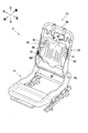
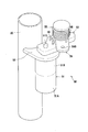
- FIG. 1 is a perspective view of a vehicle seat device as a vehicle seat device according to one embodiment. It is a perspective view of a seat frame built in a seat device for vehicles. It is an expansion perspective view of a posture control mechanism. It is a top view which shows operation
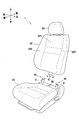
- the vehicle seat device 1 is a seat device used in a driver's seat of an automobile, and mainly includes a seat S including a seat cushion S1, a seat back S2, and a headrest S3. .
- the seat back S2 has a central portion S21 where the occupant's back hits and a side portion S22 which is disposed on the left and right of the central portion S21 of the seat back S2 and protrudes to the front side relative to the central portion S21.
- the vehicle seat device 1 can be installed at any seat position such as a passenger seat or a rear seat as well as the driver's seat.
- a seat frame F as shown in FIG. 2 is built in the seat cushion S1 and the seat back S2.
- the seat frame F is mainly composed of a seat cushion frame F1 constituting a frame of the seat cushion S1 and a seat back frame F2 constituting a frame of the seat back S2.
- the seat cushion S1 is configured by covering the seat cushion frame F1 with a seat cushion pad made of a cushioning material such as urethane foam and a skin material made of synthetic leather, cloth or the like, and the seatback S2 is made on the seatback frame F2 And a seat back pad made of a cushioning material, and a skin material made of synthetic leather, cloth or the like.
- the lower part of the seat back frame F2 is rotatably connected to the rear of the seat cushion frame F1 via a reclining mechanism RL.
- the seat back S2 can tilt back and forth with respect to the seat cushion S1.
- front, rear, right and left, and upper and lower are based on the occupant seated in the vehicle seat device 1 in a state in which the seat back S2 is not tilted by the reclining mechanism RL.
- the seat back frame F2 mainly includes the upper frame 10, the left and right side frames 20, and the lower frame 30, and the upper frame 10, the left and right side frames 20, and the lower frame 30 are integrally formed by welding or the like. It is formed in the shape of a combined frame.
- a pressure receiving member 40 for supporting the back of the occupant and a posture control mechanism 50 for changing the direction of the pressure receiving member 40 to the left and right are disposed inside the frame-like seat back frame F2.
- the pressure receiving member 40 is an elastically deformable plate-like member made of resin or the like, and is disposed behind the seat back pad between the left and right side frames 20. Specifically, the pressure receiving member 40 has a pressure receiving portion 40A that supports the occupant's back via the seat back pad, and a support portion 41 that extends laterally outward and forward from the left and right ends of the upper portion of the pressure receiving portion 40A. ing.
- the pressure receiving portion 40A is located behind the central portion S21 of the seat back S2, and the support portion 41 is located behind the side portion S22.
- the support portion 41 functions to support the upper body side from the side.
- the pressure receiving member 40 is engaged with and supported by the upper connection wire W1 and the lower connection wire W2 disposed on the rear side.
- Both ends of the upper connection wire W1 are supported by being engaged with the posture control mechanism 50, and the lower connection wires W2 are engaged with a swing mechanism 21 provided at the left and right insides of the side frame 20. It is supported.
- the pressure receiving member 40 is configured to be able to move backward when the backward movement load from the occupant acts on the seat back.
- the posture control mechanism 50 is disposed on the left and right sides of the pressure receiving member 40, and is controlled by the control device 100 (see FIG. 5) to push and move the left side or the right side of the pressure receiving member 40 forward to move the pressure receiving member 40. It is configured to be able to change the direction to the left and right.
- the posture control mechanism 50 mainly includes an actuator 51, a holding bracket 52, a first link member 53, a second link member 54, and a torsion spring 55 as a biasing member. Is configured.
- the actuator 51 is a drive source for rotating the first link member 53 and the second link member 54, and includes a stepping motor 51A capable of normal rotation and reverse rotation, a gear box 51B, and an output shaft 51C.
- the output shaft 51C is disposed along the vertical direction.
- the actuator 51 is fixed to the side frame 20 by the holding bracket 52.
- the driving force from the stepping motor 51A is decelerated by the gear box 51B and transmitted to the output shaft 51C, whereby the output shaft 51C is turned.
- the first link member 53 is a plate-like member formed in an elongated shape, and one end thereof is fixed to the output shaft 51C of the actuator 51, and the other end is in the front-rear direction centering on the output shaft 51C. It is rockable. On the upper surface of the first link member 53, two restriction walls 58 which define the swing range of the second link member 54 are provided in a protruding manner.
- the second link member 54 is rotatably connected to the first link member 53.
- a connection hole 54B is formed at the end of the second link member 54, in which the end of the upper connection wire W1 is rotatably engaged.
- the torsion spring 55 has one end engaged with the first link member 53 and the other end engaged with the second link member 54, whereby the second link member 54 with respect to the first link member 53 is viewed from above Seeing and turning clockwise.
- the left attitude control mechanism 50 is configured to be symmetrical with the right attitude control mechanism 50.
- the pressure receiving member 40 In the pressure receiving member 40, as shown in FIG. 4A, normally, the pressure receiving member 40 is positioned rearward without the left and right attitude control mechanisms 50 being operated. Then, as shown in FIG. 4B, at the time of right turn, the stepping motor 51A of the posture control mechanism 50 on the left side rotates forward by the control of the control device 100 described later, and the first link member 53 rotates forward. In operation, the pressure receiving member 40 is directed to the right. On the other hand, as shown in FIG. 4C, when turning left, the stepping motor 51A of the posture control mechanism 50 on the right side rotates forward by the control of the control device 100, and the first link member 53 rotates forward. , The pressure receiving member 40 is directed to the left. When the state of FIG.
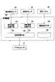
- the control device 100 drives the actuator 51 to control the left and right direction of the pressure receiving member 40, the lateral acceleration acquiring unit 110, the steering speed acquiring unit 120, and the attitude control unit 130.
- a threshold setting unit 140 and a storage device 190 are provided.
- the control device 100 includes a central processing unit (CPU), a read only memory (ROM), a random access memory (RAM), and the like (not shown), and reads and executes a program stored in advance in the storage device 190. Each of these means is realized.
- the lateral acceleration acquiring means 110 is a means for acquiring the lateral acceleration applied to the vehicle, and in the present embodiment, the lateral acceleration is obtained based on the wheel speed acquired from the wheel speed sensor 91 and the steering angle acquired from the steering angle sensor 92.
- the acceleration GC is calculated by calculation. Specifically, the lateral acceleration GC determines the vehicle speed V from the wheel speed by a known method, and uses the stability factor A which is a constant inherent to the vehicle, the hole base L of the vehicle, the steering angle ⁇ , and the turning radius R Can be calculated by the following equation.
- the steering speed acquisition means 120 is a means for acquiring the steering speed, and calculates the steering speed SV by differentiating the steering angle acquired from the steering angle sensor 92 (for example, taking the difference between the current value and the previous value).
- the steering angle ⁇ and the steering speed SV are used as the steering angle and speed of steering, but may be calculated using the steering angle and speed of the wheels if the constant is changed. Further, the lateral acceleration GC and the steering speed SV are positive on the right and negative on the left.
- the posture control means 130 controls the actuator 51 based on the lateral acceleration GC acquired by the lateral acceleration acquisition means 110 and the steering speed SV acquired by the steering speed acquisition means 120 to make the pressure receiving member 40 turn in the turning direction. It is a means to execute the sheet attitude control to turn.
- the posture control means 130 executes seat posture control when the magnitude (absolute value) of the lateral acceleration GC becomes larger than the first acceleration threshold value GCth1, and the magnitude (absolute value) of the steering speed SV is the steering speed.
- the seat attitude control is performed also when the lateral acceleration GC is larger than the threshold SVth and the magnitude of the lateral acceleration GC is smaller than the first acceleration threshold GCth1 and larger than the second acceleration threshold GCth2 opposite to the direction of the steering speed SV.
- the posture control means 130 is configured to execute the seat posture control also when predicting an increase in the lateral acceleration GC due to the turning back steering.
- Each threshold value can be determined by a traveling test according to the characteristics of the vehicle, but the steering speed threshold value SVth may be set to, for example, about 100 to 150 deg / s for a normal passenger car.
- the second acceleration threshold GCth2 be smaller than half of the first acceleration threshold GCth1. As a result, the sheet attitude control can be started at an appropriate timing to realize good hold performance.
- the first acceleration threshold value GCth1 itself is a positive value
- the lateral acceleration GC is greater than the first acceleration threshold value GCth1 in the case where the lateral acceleration GC is treated as negative as when turning right.
- This is expressed as GC ⁇ -GCth1
- other threshold values such as the second acceleration threshold value GCth2 and the steering speed threshold value SVth.
- the attitude control means 130 reverses the actuator 51 and ends the sheet attitude control.
- the magnitude of the second acceleration threshold value GCth2 is smaller than the magnitude of the reset threshold value Rth.
- the threshold setting unit 140 is a unit that receives an input from the operation panel 93 of the vehicle, writes the steering speed threshold SVth in the storage device 190, and sets it. That is, when the user operates operation panel 93 to select the magnitude of steering speed threshold value SVth from large, medium, small, etc., steering speed threshold value SVth can be changed to set a desired sense of hold. It is supposed to be.
- the storage device 190 is a device that includes a volatile storage device such as a RAM and a non-volatile storage device such as an EEPROM, and stores values acquired from each sensor, values calculated by each means, and setting values such as threshold values.
- a volatile storage device such as a RAM
- a non-volatile storage device such as an EEPROM
- control flag FL is 0 at the normal time when the seat attitude control is not performed, is 2 when the pressure receiving member 40 is directed to the left (at the time of left turn), and is directed to the right (right turn It is assumed that 1) is 1).
- the initial value of the control flag FL is zero.
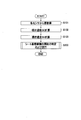
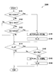
- the control device 100 acquires values from the wheel speed sensor 91 and the steering angle sensor 92 (S101), and the lateral acceleration acquiring means 110 calculates the lateral acceleration GC from the wheel speed and the steering angle ( S102). Further, the steering speed acquisition means 120 calculates the steering speed SV from the steering angle (S103). Then, the attitude control means 130 determines and executes the start of the seat attitude control in accordance with the turning direction (S200). Specifically, the process of FIG. 7 is performed if the vehicle is turning to the right, and the process of FIG. 8 is performed if the vehicle is turning to the left.
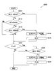
- the attitude control means 130 determines whether the lateral acceleration GC is smaller than the negative first acceleration threshold value GCth1 (the magnitude of the lateral acceleration GC is larger than GCth1). If it is smaller (S111, Yes), the left actuator 51 is rotated forward (S115), the pressure receiving member 40 is turned to the right, and the control flag FL is set to 1 (S116).
- step S111 On the other hand, even if the lateral acceleration GC is not smaller than the negative first acceleration threshold GCth1 in step S111 (S111, No), the steering speed SV is larger than the steering speed threshold SVth (S112, Yes), and If the lateral acceleration GC is opposite to the direction of the steering speed SV, that is, is smaller than the negative second acceleration threshold GCth2 (the magnitude of the lateral acceleration GC is larger than the second acceleration threshold GCth2) (S113, Yes , The left actuator 51 is rotated forward (S115), the pressure receiving member 40 is directed to the right, and the control flag FL is set to 1 (S116). If it is determined No in step S112 or step S113, and if the sheet attitude control is started, the process proceeds to step S131.
- the posture control means 130 determines whether the lateral acceleration GC is larger than the negative reset threshold Rth ( If the magnitude of the lateral acceleration GC is smaller than the reset threshold Rth) and it is larger (S132, Yes), the left actuator 51 is reversed (S133), the pressure receiving member 40 is returned to the normal state, and the control flag FL Is set to 0 (S134). On the other hand, when the control flag FL is not 1 (S131, No) and when the lateral acceleration GC is not larger than the negative reset threshold Rth (S132, No), the processing is ended without changing the control flag FL.
- the posture control means 130 determines whether the lateral acceleration GC is larger than the first acceleration threshold value GCth1. If the lateral acceleration GC is larger (S121, Yes), the right actuator 51 is rotated forward. Then, the pressure receiving member 40 is turned to the left, and the control flag FL is set to 2 (S126).
- step S121 On the other hand, even if the lateral acceleration GC is not larger than the first acceleration threshold value GCth1 in step S121 (S121, No), the steering speed SV is smaller than the negative steering speed threshold SVth (the steering speed SV is steering If the lateral acceleration GC is larger than the speed threshold SVth (S122, Yes) and the lateral acceleration GC is opposite to the direction of the steering speed SV, ie, larger than the positive second acceleration threshold GCth2 (S123, Yes) In step S125, the right actuator 51 is rotated forward (S125), the pressure receiving member 40 is turned to the left, and the control flag FL is set to 2 (S126). If it is determined No in step S122 or step S123, and if the sheet attitude control is started, the process proceeds to step S141.
- the posture control means 130 determines whether the lateral acceleration GC is smaller than the reset threshold Rth. If smaller (S142, Yes), the right actuator 51 is reversed (S141). S143) The pressure receiving member 40 is returned to the normal state, and the control flag FL is set to 0 (S144). On the other hand, when the control flag FL is not 2 (S141, No) and when the lateral acceleration GC is not larger than the negative reset threshold Rth (S142, No), the processing is ended without changing the control flag FL.
- the vehicle seat device 1 operates as shown in FIG. FIG. 9 shows changes in the steering speed SV, the lateral acceleration GC, and the control flag FL when the vehicle makes a round on the winding course.
- the driver Since the time around time t2 is the start of the right curve, the driver turns the steering back to the right a little before that, that is, when the left curve starts to end. Therefore, the steering speed SV exceeds SVth near the time t2. Then, with the steering speed SV exceeding the steering speed threshold value SVth, if the lateral acceleration GC becomes smaller than the negative second acceleration threshold value GCth2 (time t3), the pressure receiving member 40 is turned to the right.
- the pressure receiving member 40 is returned to the original state. Then, since the time around time t5 is the start of the left curve, the driver turns the steering back a little ahead, that is, from when the right curve starts to end, and turns back to the left. Therefore, at around time t5, the steering speed SV exceeds the negative steering speed threshold SVth to the negative side. Then, when the lateral acceleration GC becomes larger than the second acceleration threshold GCth2 (time t6) with the steering speed SV exceeding the negative SVth, the pressure receiving member 40 is turned to the left.
- the drive operation of the seat posture control is started only when the lateral acceleration GC exceeds the predetermined acceleration (corresponding to the first acceleration threshold GCth1).
- the drive operation of the seat attitude control has been started, but in the present embodiment, it is predicted that a large lateral acceleration GC will be generated thereafter based on the fast steering speed SV which is made by the turning back steering.
- the driving operation of the sheet attitude control can be started. Therefore, the driving operation of the seat posture control can be started earlier than in the conventional case during the time indicated by the reference D in FIG. 9, and the occupant can be held well.
- the drive operation of the seat posture control is started at an early timing when the steering is suddenly performed, for example, when turning back and forth, and the passenger holds good Can be realized.
- the vehicle seat device 1 can realize the user's favorite feeling of hold.
- the lateral acceleration acquiring unit 110 calculates and acquires the lateral acceleration based on the wheel speed and the steering angle, so that the sensitive configuration of the lateral acceleration is suppressed and stabilized with a simple configuration. Control can be performed.
- the driver's sense of hold is enhanced by changing the direction of the pressure receiving member 40 disposed behind the central portion S21 on the seatback S2 shown in FIG.
- the occupant's hold feeling may be enhanced by changing only the direction of the side portion S22 of the seat back S2 to the left or right.
- the entire seat back S2 may be moved by the actuator 51.
- the lower end of the seat back S2 is provided with the rotating shaft 61 extending downward
- the seat cushion S1 is provided with the support portion 62 rotatably supporting the rotating shaft 61
- the seat back S2 is rocked laterally with respect to the seat cushion S1.
- the attitude control mechanism 50 (actuator 51) is provided on the left and right sides of the rear portion of the seat cushion S1 and the appropriate position of the seatback S2 is pushed forward by the left and right attitude control mechanism 50 to move the entire seatback S2. be able to. Also by such a configuration, it is possible to realize a good hold of the occupant.
- the entire sheet S may be moved by the actuator 51.
- a pedestal 71 for supporting the sheet S is provided below the sheet S, and the rotary table 72 is provided on the pedestal 71. Then, the sheet S is fixed to the rotary table 72.
- posture control mechanisms 50 actuator 51
- the entire seat S can be moved. It can. Also by such a configuration, it is possible to realize a good hold of the occupant.
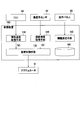
- the lateral acceleration is obtained by calculation based on the wheel speed and the steering angle, but may be obtained from the lateral acceleration sensor 94 as in the third modification shown in FIG.
- the lateral acceleration and the steering speed may be acquired by inquiring of the electronic control unit (ECU) 95 as in the fourth modification shown in FIG. Good.
- the increase in lateral acceleration due to the turning back is predicted based on the steering speed and the lateral acceleration, but the lateral acceleration due to the turning back steering is predicted based on the steering speed regardless of the lateral acceleration.
- vehicle seat device 1 used in a car is illustrated as a vehicle seat device in the above embodiment, the present invention is not limited to this, and other vehicle seat devices such as snowmobiles, ships, aircraft It can also be applied to sheets used in
Landscapes
- Engineering & Computer Science (AREA)
- Aviation & Aerospace Engineering (AREA)
- Transportation (AREA)
- Mechanical Engineering (AREA)
- Seats For Vehicles (AREA)
- Chair Legs, Seat Parts, And Backrests (AREA)
Priority Applications (3)
| Application Number | Priority Date | Filing Date | Title |
|---|---|---|---|
| JP2015536592A JP6204480B2 (ja) | 2013-09-10 | 2014-09-10 | 乗物用シート装置 |
| US14/916,103 US10173552B2 (en) | 2013-09-10 | 2014-09-10 | Seat device for vehicle |
| US16/210,570 US20190126782A1 (en) | 2013-09-10 | 2018-12-05 | Seat device for vehicle |
Applications Claiming Priority (2)
| Application Number | Priority Date | Filing Date | Title |
|---|---|---|---|
| JP2013-187610 | 2013-09-10 | ||
| JP2013187610 | 2013-09-10 |
Related Child Applications (2)
| Application Number | Title | Priority Date | Filing Date |
|---|---|---|---|
| US14/916,103 A-371-Of-International US10173552B2 (en) | 2013-09-10 | 2014-09-10 | Seat device for vehicle |
| US16/210,570 Continuation US20190126782A1 (en) | 2013-09-10 | 2018-12-05 | Seat device for vehicle |
Publications (1)
| Publication Number | Publication Date |
|---|---|
| WO2015037600A1 true WO2015037600A1 (ja) | 2015-03-19 |
Family
ID=52665702
Family Applications (1)
| Application Number | Title | Priority Date | Filing Date |
|---|---|---|---|
| PCT/JP2014/073873 Ceased WO2015037600A1 (ja) | 2013-09-10 | 2014-09-10 | 乗物用シート装置 |
Country Status (3)
| Country | Link |
|---|---|
| US (2) | US10173552B2 (https=) |
| JP (4) | JP6204480B2 (https=) |
| WO (1) | WO2015037600A1 (https=) |
Cited By (15)
| Publication number | Priority date | Publication date | Assignee | Title |
|---|---|---|---|---|
| JP2017081458A (ja) * | 2015-10-29 | 2017-05-18 | テイ・エス テック株式会社 | 乗物用シート |
| JP2018122832A (ja) * | 2017-02-03 | 2018-08-09 | 本田技研工業株式会社 | 車両システム、車両制御方法、および車両制御プログラム |
| JP2018122613A (ja) * | 2017-01-30 | 2018-08-09 | 本田技研工業株式会社 | 車両制御システム、車両制御方法、および車両制御プログラム |
| JP2019177878A (ja) * | 2019-07-29 | 2019-10-17 | テイ・エス テック株式会社 | 乗物用シート |
| US10703225B2 (en) | 2018-02-06 | 2020-07-07 | Honda Motor Co., Ltd. | Vehicle seat |
| JP2020186723A (ja) * | 2019-03-06 | 2020-11-19 | トヨタ モーター エンジニアリング アンド マニュファクチャリング ノース アメリカ,インコーポレイティド | 変形部分を有するアクティブ乗物座席 |
| JP2021011153A (ja) * | 2019-07-04 | 2021-02-04 | テイ・エス テック株式会社 | 車両用シート装置 |
| JP2021165145A (ja) * | 2016-10-19 | 2021-10-14 | テイ・エス テック株式会社 | 乗物用シート |
| US12152570B2 (en) | 2023-02-22 | 2024-11-26 | Toyota Motor Engineering & Manufacturing North America, Inc. | Shape memory material member-based actuator with electrostatic clutch preliminary class |
| US12163507B2 (en) | 2023-02-22 | 2024-12-10 | Toyota Motor Engineering & Manufacturing North America, Inc. | Contracting member-based actuator with clutch |
| US12234811B1 (en) | 2023-08-21 | 2025-02-25 | Toyota Motor Engineering & Manufacturing North America, Inc. | Monitoring a state of a shape memory material member |
| US12241458B2 (en) | 2023-02-16 | 2025-03-04 | Toyota Motor Engineering & Manufacturing North America, Inc. | Actuator with contracting member |
| US12270386B2 (en) | 2023-02-16 | 2025-04-08 | Toyota Motor Engineering & Manufacturing North America, Inc. | Shape memory material member-based actuator |
| US12383066B2 (en) | 2022-04-26 | 2025-08-12 | Toyota Motor Engineering & Manufacturing North America, Inc. | Chair with shape memory material-based movement synchronized with visual content |
| US12589512B2 (en) | 2023-12-28 | 2026-03-31 | Toyota Motor Engineering & Manufacturing North America, Inc. | Shearing tool with closure assist |
Families Citing this family (15)
| Publication number | Priority date | Publication date | Assignee | Title |
|---|---|---|---|---|
| US10173552B2 (en) * | 2013-09-10 | 2019-01-08 | Ts Tech Co., Ltd. | Seat device for vehicle |
| JP6492963B2 (ja) * | 2015-05-20 | 2019-04-03 | アイシン精機株式会社 | 荷重検出装置 |
| JP6578891B2 (ja) * | 2015-11-05 | 2019-09-25 | アイシン精機株式会社 | 乗員検知方法及び乗員検知装置 |
| JP6933481B2 (ja) * | 2017-03-28 | 2021-09-08 | 本田技研工業株式会社 | 車両シート制御装置、車両シート制御方法、及びプログラム |
| DE102017215908A1 (de) * | 2017-09-08 | 2019-03-14 | Brose Fahrzeugteile Gmbh & Co. Kg, Coburg | Sitzversteller mit Kennfeldsteuerung und Verfahren zur Sitzverstellung |
| EP3470260B1 (fr) * | 2017-10-16 | 2022-08-31 | FAURECIA Sièges d'Automobile | Système de gestion des réglages de siège dans un véhicule |
| CN108454467B (zh) * | 2017-12-15 | 2021-07-23 | 蔚来(安徽)控股有限公司 | 用于车辆座椅的控制方法、系统、应用程序和计算机设备 |
| JP6825591B2 (ja) * | 2018-02-22 | 2021-02-03 | トヨタ自動車株式会社 | 車両用シート |
| US10830634B2 (en) * | 2018-03-06 | 2020-11-10 | Deere & Company | Fill level detection and control |
| US11667222B1 (en) * | 2018-08-08 | 2023-06-06 | Waymo Llc | Vehicle mechanisms that alter a vehicle cabin to reduce motion sickness |
| US11752901B2 (en) * | 2019-03-28 | 2023-09-12 | Toyota Motor Engineering & Manufacturing North America, Inc. | Vehicle seat with tilting seat portion |
| US11557096B2 (en) * | 2019-12-09 | 2023-01-17 | At&T Intellectual Property I, L.P. | Cognitive stimulation in vehicles |
| EP4405192A4 (en) * | 2021-09-22 | 2025-07-02 | Ericsson Telefon Ab L M | VIRTUAL REALITY GAMING EXPERIENCE IN AN AUTONOMOUS VEHICLE |
| US11897379B2 (en) | 2021-10-20 | 2024-02-13 | Toyota Motor Engineering & Manufacturing North America, Inc. | Seat with shape memory material member actuation |
| JP7740032B2 (ja) * | 2022-01-19 | 2025-09-17 | 日産自動車株式会社 | 車両用座席の制御方法及び制御装置 |
Citations (3)
| Publication number | Priority date | Publication date | Assignee | Title |
|---|---|---|---|---|
| JP2007261522A (ja) * | 2006-03-29 | 2007-10-11 | Aisin Seiki Co Ltd | 車両用シート位置制御装置 |
| JP2008174182A (ja) * | 2007-01-22 | 2008-07-31 | Aisin Seiki Co Ltd | 車両用シート装置 |
| JP2013049357A (ja) * | 2011-08-31 | 2013-03-14 | Ts Tech Co Ltd | シート装置 |
Family Cites Families (25)
| Publication number | Priority date | Publication date | Assignee | Title |
|---|---|---|---|---|
| US6507779B2 (en) * | 1995-06-07 | 2003-01-14 | Automotive Technologies International, Inc. | Vehicle rear seat monitor |
| US4655505A (en) * | 1984-12-13 | 1987-04-07 | Nhk Spring Co., Ltd. | Pneumatically controlled seat for vehicle |
| JPS6485845A (en) * | 1986-06-27 | 1989-03-30 | Nippon Soken | Vehicle seat with rotary type back rest |
| JPH04123200A (ja) | 1990-09-12 | 1992-04-23 | Mazda Motor Corp | 車両の安全確認支援装置 |
| US6784379B2 (en) * | 1995-06-07 | 2004-08-31 | Automotive Technologies International, Inc. | Arrangement for obtaining information about an occupying item of a seat |
| US9290146B2 (en) * | 1992-05-05 | 2016-03-22 | Intelligent Technologies International, Inc. | Optical monitoring of vehicle interiors |
| US7900736B2 (en) * | 1995-06-07 | 2011-03-08 | Automotive Technologies International, Inc. | Vehicular seats with fluid-containing weight sensing system |
| US7387183B2 (en) * | 1995-06-07 | 2008-06-17 | Automotive Technologies International, Inc. | Weight measuring systems and methods for vehicles |
| US6122912A (en) * | 1997-10-16 | 2000-09-26 | Techco Corporation | Electro-hydraulic power steering systems having improved efficiency |
| US6677720B2 (en) * | 2001-06-08 | 2004-01-13 | Dura Global Technologies, Inc. | Control system for vehicle seat |
| JP2003011706A (ja) * | 2001-07-05 | 2003-01-15 | Araco Corp | 車両用シート |
| WO2003091082A2 (de) * | 2002-04-25 | 2003-11-06 | Bosch Rexroth Ag | Hydraulische lenkeinrichtung |
| DE10330028A1 (de) * | 2003-07-03 | 2005-04-07 | Ims Gear Gmbh | Fahrzeug-Sitzabschnitt-Verstellvorrichtung |
| JP5055789B2 (ja) * | 2006-02-24 | 2012-10-24 | アイシン精機株式会社 | 車両用シート装置 |
| GB2440732A (en) * | 2006-08-09 | 2008-02-13 | Agco Gmbh | A reversible driving arrangement for a tractor |
| JP4845642B2 (ja) * | 2006-08-24 | 2011-12-28 | トヨタ自動車株式会社 | 車両用シート制御装置 |
| JP5046662B2 (ja) * | 2007-01-24 | 2012-10-10 | アイシン精機株式会社 | 車両用シート装置 |
| JP4422756B2 (ja) * | 2007-12-21 | 2010-02-24 | トヨタ自動車株式会社 | 乗物用シート装置 |
| JP5485562B2 (ja) * | 2009-02-09 | 2014-05-07 | 株式会社アドヴィックス | 車両のシート制御装置 |
| JP5544093B2 (ja) * | 2009-02-09 | 2014-07-09 | 株式会社アドヴィックス | 車両のシート制御装置 |
| JP5544095B2 (ja) * | 2009-02-12 | 2014-07-09 | 株式会社アドヴィックス | 車両のシート制御装置 |
| EP2752333B1 (en) * | 2011-08-31 | 2018-07-25 | TS Tech Co., Ltd. | Seat apparatus |
| US8744694B2 (en) * | 2012-04-17 | 2014-06-03 | Bose Corporation | Active suspension seat and vehicle operation interlocks |
| US10173552B2 (en) * | 2013-09-10 | 2019-01-08 | Ts Tech Co., Ltd. | Seat device for vehicle |
| JP6015717B2 (ja) * | 2014-07-08 | 2016-10-26 | トヨタ自動車株式会社 | 車両用シート |
-
2014
- 2014-09-10 US US14/916,103 patent/US10173552B2/en active Active
- 2014-09-10 WO PCT/JP2014/073873 patent/WO2015037600A1/ja not_active Ceased
- 2014-09-10 JP JP2015536592A patent/JP6204480B2/ja active Active
-
2017
- 2017-08-31 JP JP2017166614A patent/JP6479914B2/ja active Active
-
2018
- 2018-12-05 US US16/210,570 patent/US20190126782A1/en not_active Abandoned
-
2019
- 2019-02-06 JP JP2019019553A patent/JP6761195B2/ja active Active
-
2020
- 2020-09-03 JP JP2020147977A patent/JP2020192982A/ja active Pending
Patent Citations (3)
| Publication number | Priority date | Publication date | Assignee | Title |
|---|---|---|---|---|
| JP2007261522A (ja) * | 2006-03-29 | 2007-10-11 | Aisin Seiki Co Ltd | 車両用シート位置制御装置 |
| JP2008174182A (ja) * | 2007-01-22 | 2008-07-31 | Aisin Seiki Co Ltd | 車両用シート装置 |
| JP2013049357A (ja) * | 2011-08-31 | 2013-03-14 | Ts Tech Co Ltd | シート装置 |
Cited By (25)
| Publication number | Priority date | Publication date | Assignee | Title |
|---|---|---|---|---|
| JP2017081458A (ja) * | 2015-10-29 | 2017-05-18 | テイ・エス テック株式会社 | 乗物用シート |
| JP2021165145A (ja) * | 2016-10-19 | 2021-10-14 | テイ・エス テック株式会社 | 乗物用シート |
| JP7311798B2 (ja) | 2016-10-19 | 2023-07-20 | テイ・エス テック株式会社 | 乗物用シート |
| JP2018122613A (ja) * | 2017-01-30 | 2018-08-09 | 本田技研工業株式会社 | 車両制御システム、車両制御方法、および車両制御プログラム |
| JP2018122832A (ja) * | 2017-02-03 | 2018-08-09 | 本田技研工業株式会社 | 車両システム、車両制御方法、および車両制御プログラム |
| US10486553B2 (en) | 2017-02-03 | 2019-11-26 | Honda Motor Co., Ltd. | Vehicle system, vehicle control method, and storage medium |
| US10703225B2 (en) | 2018-02-06 | 2020-07-07 | Honda Motor Co., Ltd. | Vehicle seat |
| JP7350677B2 (ja) | 2019-03-06 | 2023-09-26 | トヨタ モーター エンジニアリング アンド マニュファクチャリング ノース アメリカ,インコーポレイティド | 変形部分を有するアクティブ乗物座席 |
| JP2020186723A (ja) * | 2019-03-06 | 2020-11-19 | トヨタ モーター エンジニアリング アンド マニュファクチャリング ノース アメリカ,インコーポレイティド | 変形部分を有するアクティブ乗物座席 |
| JP7586966B2 (ja) | 2019-03-06 | 2024-11-19 | トヨタ モーター エンジニアリング アンド マニュファクチャリング ノース アメリカ,インコーポレイティド | 変形部分を有するアクティブ乗物座席 |
| JP2023138954A (ja) * | 2019-03-06 | 2023-10-03 | トヨタ モーター エンジニアリング アンド マニュファクチャリング ノース アメリカ,インコーポレイティド | 変形部分を有するアクティブ乗物座席 |
| JP2023168607A (ja) * | 2019-07-04 | 2023-11-24 | テイ・エス テック株式会社 | 車両用シート装置 |
| JP2021011153A (ja) * | 2019-07-04 | 2021-02-04 | テイ・エス テック株式会社 | 車両用シート装置 |
| JP7709067B2 (ja) | 2019-07-04 | 2025-07-16 | テイ・エス テック株式会社 | 車両用シート装置 |
| JP7365550B2 (ja) | 2019-07-04 | 2023-10-20 | テイ・エス テック株式会社 | 車両用シート装置 |
| JP2019177878A (ja) * | 2019-07-29 | 2019-10-17 | テイ・エス テック株式会社 | 乗物用シート |
| JP2021120267A (ja) * | 2019-07-29 | 2021-08-19 | テイ・エス テック株式会社 | 乗物用シート |
| JP7161127B2 (ja) | 2019-07-29 | 2022-10-26 | テイ・エス テック株式会社 | 乗物用シート |
| US12383066B2 (en) | 2022-04-26 | 2025-08-12 | Toyota Motor Engineering & Manufacturing North America, Inc. | Chair with shape memory material-based movement synchronized with visual content |
| US12241458B2 (en) | 2023-02-16 | 2025-03-04 | Toyota Motor Engineering & Manufacturing North America, Inc. | Actuator with contracting member |
| US12270386B2 (en) | 2023-02-16 | 2025-04-08 | Toyota Motor Engineering & Manufacturing North America, Inc. | Shape memory material member-based actuator |
| US12152570B2 (en) | 2023-02-22 | 2024-11-26 | Toyota Motor Engineering & Manufacturing North America, Inc. | Shape memory material member-based actuator with electrostatic clutch preliminary class |
| US12163507B2 (en) | 2023-02-22 | 2024-12-10 | Toyota Motor Engineering & Manufacturing North America, Inc. | Contracting member-based actuator with clutch |
| US12234811B1 (en) | 2023-08-21 | 2025-02-25 | Toyota Motor Engineering & Manufacturing North America, Inc. | Monitoring a state of a shape memory material member |
| US12589512B2 (en) | 2023-12-28 | 2026-03-31 | Toyota Motor Engineering & Manufacturing North America, Inc. | Shearing tool with closure assist |
Also Published As
| Publication number | Publication date |
|---|---|
| US20190126782A1 (en) | 2019-05-02 |
| JP6761195B2 (ja) | 2020-09-23 |
| JP2020192982A (ja) | 2020-12-03 |
| JP2019069776A (ja) | 2019-05-09 |
| US10173552B2 (en) | 2019-01-08 |
| JP6204480B2 (ja) | 2017-09-27 |
| JP6479914B2 (ja) | 2019-03-06 |
| US20160221475A1 (en) | 2016-08-04 |
| JP2017206259A (ja) | 2017-11-24 |
| JPWO2015037600A1 (ja) | 2017-03-02 |
Similar Documents
| Publication | Publication Date | Title |
|---|---|---|
| JP6761195B2 (ja) | 乗物用シート装置 | |
| JP6589558B2 (ja) | 乗物用シート | |
| JP6558503B2 (ja) | スイッチ位置の調整方法及び車両用操作装置 | |
| US10703225B2 (en) | Vehicle seat | |
| WO2016147712A1 (ja) | 乗物用シート | |
| JP2018079818A (ja) | 車両用シートの調整方法及び車両用シートの調整装置 | |
| WO2019124172A1 (ja) | 車両シート制御装置 | |
| WO2017104365A1 (ja) | 自動運転制御システム、運転情報出力装置、およびフットレスト | |
| JP6063978B2 (ja) | 乗物用シート | |
| JP4268192B2 (ja) | 車両用シート装置 | |
| JP6933824B2 (ja) | 乗物用シート | |
| JP6601160B2 (ja) | 乗物用シート | |
| JP6540123B2 (ja) | 車両用シート | |
| JP2006027394A (ja) | 入力制御装置 | |
| JP6741960B2 (ja) | 乗物用シート | |
| JP6982257B2 (ja) | 車両用シート | |
| JP2021120267A (ja) | 乗物用シート | |
| JP6460864B2 (ja) | 乗物用シート | |
| WO2009096128A1 (ja) | 車両の乗員姿勢制御装置 | |
| JP2024152221A (ja) | 車両用制御装置 | |
| JP5176939B2 (ja) | 車両制御装置 | |
| JP2020104792A (ja) | 車両用シート | |
| JP2016064827A (ja) | 乗物用シート |
Legal Events
| Date | Code | Title | Description |
|---|---|---|---|
| 121 | Ep: the epo has been informed by wipo that ep was designated in this application |
Ref document number: 14843438 Country of ref document: EP Kind code of ref document: A1 |
|
| ENP | Entry into the national phase |
Ref document number: 2015536592 Country of ref document: JP Kind code of ref document: A |
|
| WWE | Wipo information: entry into national phase |
Ref document number: 14916103 Country of ref document: US |
|
| NENP | Non-entry into the national phase |
Ref country code: DE |
|
| 122 | Ep: pct application non-entry in european phase |
Ref document number: 14843438 Country of ref document: EP Kind code of ref document: A1 |