WO2015015797A1 - 燃料噴射弁 - Google Patents
燃料噴射弁 Download PDFInfo
- Publication number
- WO2015015797A1 WO2015015797A1 PCT/JP2014/003967 JP2014003967W WO2015015797A1 WO 2015015797 A1 WO2015015797 A1 WO 2015015797A1 JP 2014003967 W JP2014003967 W JP 2014003967W WO 2015015797 A1 WO2015015797 A1 WO 2015015797A1
- Authority
- WO
- WIPO (PCT)
- Prior art keywords
- nozzle hole
- hole
- nozzle
- fuel
- reference inner
- Prior art date
- Legal status (The legal status is an assumption and is not a legal conclusion. Google has not performed a legal analysis and makes no representation as to the accuracy of the status listed.)
- Ceased
Links
Images


Classifications
-
- F—MECHANICAL ENGINEERING; LIGHTING; HEATING; WEAPONS; BLASTING
- F02—COMBUSTION ENGINES; HOT-GAS OR COMBUSTION-PRODUCT ENGINE PLANTS
- F02M—SUPPLYING COMBUSTION ENGINES IN GENERAL WITH COMBUSTIBLE MIXTURES OR CONSTITUENTS THEREOF
- F02M61/00—Fuel-injectors not provided for in groups F02M39/00 - F02M57/00 or F02M67/00
- F02M61/16—Details not provided for in, or of interest apart from, the apparatus of groups F02M61/02 - F02M61/14
- F02M61/18—Injection nozzles, e.g. having valve seats; Details of valve member seated ends, not otherwise provided for
- F02M61/1806—Injection nozzles, e.g. having valve seats; Details of valve member seated ends, not otherwise provided for characterised by the arrangement of discharge orifices, e.g. orientation or size
- F02M61/1846—Dimensional characteristics of discharge orifices
-
- F—MECHANICAL ENGINEERING; LIGHTING; HEATING; WEAPONS; BLASTING
- F02—COMBUSTION ENGINES; HOT-GAS OR COMBUSTION-PRODUCT ENGINE PLANTS
- F02M—SUPPLYING COMBUSTION ENGINES IN GENERAL WITH COMBUSTIBLE MIXTURES OR CONSTITUENTS THEREOF
- F02M61/00—Fuel-injectors not provided for in groups F02M39/00 - F02M57/00 or F02M67/00
- F02M61/16—Details not provided for in, or of interest apart from, the apparatus of groups F02M61/02 - F02M61/14
- F02M61/18—Injection nozzles, e.g. having valve seats; Details of valve member seated ends, not otherwise provided for
- F02M61/1806—Injection nozzles, e.g. having valve seats; Details of valve member seated ends, not otherwise provided for characterised by the arrangement of discharge orifices, e.g. orientation or size
- F02M61/1826—Discharge orifices having different sizes
-
- F—MECHANICAL ENGINEERING; LIGHTING; HEATING; WEAPONS; BLASTING
- F02—COMBUSTION ENGINES; HOT-GAS OR COMBUSTION-PRODUCT ENGINE PLANTS
- F02M—SUPPLYING COMBUSTION ENGINES IN GENERAL WITH COMBUSTIBLE MIXTURES OR CONSTITUENTS THEREOF
- F02M61/00—Fuel-injectors not provided for in groups F02M39/00 - F02M57/00 or F02M67/00
- F02M61/16—Details not provided for in, or of interest apart from, the apparatus of groups F02M61/02 - F02M61/14
- F02M61/18—Injection nozzles, e.g. having valve seats; Details of valve member seated ends, not otherwise provided for
- F02M61/1806—Injection nozzles, e.g. having valve seats; Details of valve member seated ends, not otherwise provided for characterised by the arrangement of discharge orifices, e.g. orientation or size
- F02M61/1833—Discharge orifices having changing cross sections, e.g. being divergent
Definitions
- the present disclosure relates to a fuel injection valve that injects fuel into a combustion chamber of an internal combustion engine.
- the fuel injection valves disclosed in Patent Documents 1 and 2 are formed with a plurality of injection holes for injecting fuel into the combustion chamber.
- the inner diameter of one nozzle hole is different from the inner diameter of the other nozzle holes.
- the characteristics of the spray injected from each injection hole may be different from each other. Therefore, the particle sizes of the fuel injected from the nozzle holes may be different from each other, or the manner of spread of the spray injected from the nozzle holes may be different from each other.
- An object of the present disclosure is to provide a fuel injection valve capable of approximating the characteristics of spray injected from each nozzle hole even if the inner diameters of the plurality of nozzle holes formed in the fuel injection valve are different from each other. It is in.
- the plurality of injection holes formed in the fuel injection valve include a first injection hole and a second injection hole having different reference inner diameters.
- the value obtained by dividing the channel length of the first nozzle hole by the reference inner diameter of the first nozzle hole is the same as the value obtained by dividing the channel length of the second nozzle hole by the reference inner diameter of the second nozzle hole.
- the inventors of the present application have found that the atomization characteristics of the spray in the fuel injection valve are related to the ratio of the flow path length of the nozzle hole and the reference inner diameter. Therefore, in the first aspect, the value obtained by dividing the flow path length by the reference inner diameter is the same in the first nozzle hole and the second nozzle hole. Therefore, even if the reference inner diameters of these nozzle holes are different from each other, the atomization characteristics of the first nozzle hole and the second nozzle hole can be approximated to each other.
- the fuel injection valve can reduce the variation in the particle size of the spray injected from each nozzle hole while forming a spray shape suitable for the fuel chamber of the internal combustion engine.
- the inventor of the present application also found a relationship between the rate of change of the spray injected from the nozzle hole and the value obtained by dividing the flow path length of the nozzle hole by the reference inner diameter.
- the first injection hole and the second injection hole have a cylindrical hole shape that extends while maintaining each reference inner diameter, and the flow path length of the first injection hole is set to the first injection hole. Both the value divided by the reference inner diameter of the hole and the value obtained by dividing the flow path length of the second injection hole by the reference inner diameter of the second injection hole are 1.45 or more.
- the first injection hole and the second injection hole have a tapered hole shape that expands from each reference inner diameter toward the fuel downstream side from the fuel upstream side, Both the value obtained by dividing the flow path length by the reference inner diameter of the first injection hole and the value obtained by dividing the flow path length of the second injection hole by the reference inner diameter of the second injection hole are both 2.0 or more. It is a feature.
- the fuel flowing through the nozzle hole can have a rectifying action. Therefore, the spray injected from the nozzle hole is stably formed in the center line direction of the nozzle hole.
- the value obtained by dividing the flow path length by the reference inner diameter is equal to or greater than the predetermined value described above, even if the reference inner diameters of the first injection hole and the second injection hole are different from each other, they are injected from these injection holes.
- the rate of change of the sprays that are close to each other is a stable value. Therefore, the fuel injection valve can stably form a spray having a shape suitable for the fuel chamber of the internal combustion engine.
- the inventor of the present application has a correlation with the value obtained by dividing the flow path length by the reference inner diameter with respect to the length of the spray injected from the nozzle hole in which the reference inner diameter is maintained (hereinafter referred to as “spray length”). I found it. Therefore, according to the fourth aspect of the present disclosure, the value obtained by dividing the flow path length of the first injection hole by the reference inner diameter of the first injection hole, and the flow path length of the second injection hole are set to those of the second injection hole. Both values divided by the reference inner diameter are 1.85 or less.
- the fuel injection valve can form a spray having a more optimal shape in the fuel chamber of the internal combustion engine.
- FIG. 3 is a sectional view taken along line III-III in FIG. 2. It is sectional drawing which expands and shows the vicinity of a 1st nozzle hole further. It is sectional drawing which expands and shows the vicinity of a 2nd nozzle hole further. It is a figure which shows the change of the characteristic of the spray accompanying the increase / decrease in L / D value in a cylindrical hole-shaped nozzle hole. It is sectional drawing which expands and shows the vicinity of the sack part of a 2nd form. It is sectional drawing which expands and shows the vicinity of a 1st nozzle hole further.
- a fuel injection valve 10 according to the first embodiment shown in FIG. 1 is installed in a gasoline engine and injects fuel into a combustion chamber (not shown) provided in the gasoline engine.
- the fuel injection valve 10 may inject fuel into an intake passage that communicates with a combustion chamber of a gasoline engine, or may inject fuel into a combustion chamber of a diesel engine.
- the fuel injection valve 10 includes a valve body 11, a fixed core 20, a movable core 30, a valve member 40, an elastic member 50, and a drive unit 60.
- the valve body 11 includes a core housing 12, an inlet member 13, a nozzle holder 14, a nozzle body 15, and the like.
- the core housing 12 is formed in a cylindrical shape, and includes a first magnetic portion 12a, a nonmagnetic portion 12b, and a second magnetic portion 12c in order from one end side in the axial direction toward the other end side.
- the magnetic portions 12a and 12c made of a magnetic material and the nonmagnetic portion 12b made of a nonmagnetic material are coupled by laser welding or the like.
- the nonmagnetic portion 12b prevents the magnetic flux from being short-circuited between the first magnetic portion 12a and the second magnetic portion 12c.
- a cylindrical inlet member 13 is fixed to one end of the second magnetic portion 12c.
- the inlet member 13 forms a fuel inlet 13a to which fuel is supplied from a fuel pump (not shown).
- a fuel filter 16 is fixed to the inner peripheral side of the inlet member 13 in order to filter the fuel supplied to the fuel inlet 13a and guide it into the core housing 12 on the downstream side.
- a nozzle body 15 is fixed to one end of the first magnetic part 12a via a nozzle holder 14 formed in a cylindrical shape by a magnetic material.
- the nozzle body 15 is formed in a bottomed cylindrical shape, and a fuel passage 17 is formed on the inner peripheral side in cooperation with the core housing 12 and the nozzle holder 14.
- the nozzle body 15 has a valve seat portion 150 and a sack portion 152.
- the valve seat portion 150 forms a valve seat surface 151 by a tapered inner peripheral surface that is reduced in diameter at a constant reduction rate toward the downstream side of the fuel.
- the sack portion 152 is formed on the fuel downstream side of the valve seat portion 150.
- the sack portion 152 forms a recess 153 that opens toward the fuel passage 17.
- a nozzle hole 155 communicating with the sac chamber 154 opens on the inner surface of the sac chamber 154.
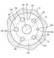
- a plurality of nozzle holes 155 are provided around the central axis 18 of the nozzle body 15 at intervals.
- Each inlet-side opening 156 of each nozzle hole 155 is located on the same virtual circle 19 around the central axis 18. Further, each nozzle hole 155 is inclined toward the outer peripheral side of the recess 153 toward the respective outlet side openings 157.
- the fixed core 20 is formed of a magnetic material in a cylindrical shape, and is fixed coaxially to the inner peripheral surfaces of the nonmagnetic portion 12b and the second magnetic portion 12c in the core housing 12.
- the fixed core 20 is provided with a through hole 20a that penetrates the central portion in the radial direction in the axial direction. The fuel that flows into the through hole 20a from the fuel inlet 13a through the fuel filter 16 flows in the through hole 20a toward the movable core 30 side.
- the movable core 30 is formed of a magnetic material in a stepped cylindrical shape, and is coaxially disposed on the inner peripheral side of the core housing 12 and faces the fixed core 20 on the upstream side of the fuel in the axial direction.
- the movable core 30 is guided by the inner peripheral wall of the nonmagnetic portion 12b of the core housing 12, so that the movable core 30 can be accurately reciprocated on both sides in the axial direction.
- the movable core 30 has a first through hole 30a that penetrates the radial center portion in the axial direction and a second through hole 30b that penetrates the axial middle portion in the radial direction and communicates with the first through hole 30a. , Provided.
- the fuel that has flowed out of the through hole 20 a of the fixed core 20 flows into the first through hole 30 a of the movable core 30 and flows from the second through hole 30 b to the fuel passage 17 in the core housing 12.
- the valve member 40 is formed of a nonmagnetic material in the shape of a needle having a circular cross section. Elements 12, 14, 15 of the valve body 11 are coaxially arranged in the fuel passage 17. One end of the valve member 40 is coaxially fixed to the inner peripheral surface of the first through hole 30 a of the movable core 30. As shown in FIGS. 1 and 2, the other end portion of the valve member 40 forms a contact portion 41 whose diameter decreases toward the downstream side of the fuel, and the contact portion 41 against the valve seat surface 151. Are opposed to each other. The valve member 40 causes the contact portion 41 to be separated from and seated on the valve seat surface 151 by displacement along the central axis 18. Thus, the fuel injection from the nozzle hole 155 is interrupted.
- valve member 40 when the valve member 40 is opened so that the contact portion 41 is separated from the valve seat surface 151, fuel flows from the fuel passage 17 into the sac chamber 154 and is injected from each nozzle hole 155 into the combustion chamber. The On the other hand, when the valve member 40 is closed so that the contact portion 41 is seated on the valve seat surface 151, the fuel injection from each nozzle hole 155 to the combustion chamber is blocked.
- the elastic member 50 is made of a metal compression coil spring, and is accommodated coaxially on the inner peripheral side of the through hole 20 a provided in the fixed core 20.
- One end of the elastic member 50 is locked to the axial end of the adjusting pipe 22 fixed to the inner peripheral surface of the through hole 20a.
- the other end of the elastic member 50 is locked to the inner surface of the first through hole 30 a of the movable core 30.
- the elastic member 50 is elastically deformed by being compressed between the elements 22 and 30 sandwiching the elastic member 50. Therefore, the restoring force generated by the elastic deformation of the elastic member 50 becomes an urging force for urging the movable core 30 together with the valve member 40 toward the fuel downstream side.
- the driving unit 60 includes a coil 61, a resin bobbin 62, a magnetic yoke 63, a connector 64, and the like.
- the coil 61 is formed by winding a metal wire around a resin bobbin 62, and a magnetic yoke 63 is disposed on the outer peripheral side thereof.
- the coil 61 is coaxially fixed to the outer peripheral surfaces of the nonmagnetic portion 12 b and the second magnetic portion 12 c on the outer peripheral side of the fixed core 20 in the core housing 12 via a resin bobbin 62.
- the coil 61 is electrically connected to an external control circuit (not shown) via a terminal 64a provided on the connector 64, and energization is controlled by the control circuit.
- the magnetic yoke 63, the nozzle holder 14, the first magnetic part 12a, the movable core 30, the fixed core 20, and the second magnetic part 12c form a magnetic circuit together. Flows. As a result, a magnetic attractive force that attracts the movable core 30 toward the fixed core 20 on the upstream side of the fuel is generated between the movable core 30 and the fixed core 20.
- the coil 61 is demagnetized by stopping energization, the magnetic flux does not flow in the magnetic circuit described above, and the magnetic attractive force disappears between the movable core 30 and the fixed core 20.
- the magnetic attractive force acting on the movable core 30 disappears by stopping energization of the coil 61.
- the movable core 30 moves together with the valve member 40 toward the biasing side due to the restoring force of the elastic member 50, and the valve member 40 is brought into contact with the valve seat surface 151 and stopped.
- the contact portion 41 is seated on the valve seat surface 151, and fuel injection from each nozzle hole 155 is stopped.
- the bottom wall 160 of the recess 153 is formed to face the valve member 40 having the contact portion 41 seated on the valve seat surface 151 with a distance. Between the front end surface 42 of the valve member 40 and the bottom wall 160 when the contact portion 41 is seated on the valve seat surface 151, a sac chamber 154 that communicates with each nozzle hole 155 is formed. The volume of the sac chamber 154 is defined so that foreign matters in the fuel can be prevented from getting caught between the valve member 40 and the valve seat surface 151.
- a central surface portion 161 and a tapered surface portion 162 are formed on the bottom surface of the bottom wall 160. Further, a connection surface 168 is formed on the outer peripheral side of the bottom surface.
- the central surface portion 161 is a flat surface formed in a perfect circle shape, and is positioned coaxially with the central axis 18.
- the taper surface portion 162 is formed in a tapered surface shape whose diameter is reduced at a constant diameter reduction rate toward the center surface portion 161 on the fuel downstream side in the axial direction.
- the connection surface 168 is formed in a concave curved surface shape whose diameter reduction rate increases toward the downstream side of the fuel, and connects the outer peripheral side of the tapered surface portion 162 and the inner peripheral side of the valve seat surface 151.
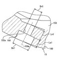
- a plurality of injection holes 155 including a first injection hole 155a and a second injection hole 155b are formed in the bottom wall 160. Both the first nozzle hole 155a and the second nozzle hole 155b are formed in a cylindrical hole shape.
- the first injection hole 155a and the second injection hole 155b extend in the bottom wall 160 in a posture in which the respective central axes (hereinafter referred to as “injection hole axis”) intersect the tapered surface portion 162.
- injection hole axis Each nozzle hole axis 159a, 159b obliquely intersects the tapered surface portion 162, and is inclined toward the outer periphery of the nozzle body 15 from the inlet side opening 156 toward the outlet side opening 157.
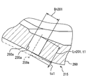
- the inner diameter maintained substantially constant in the first nozzle hole 155a shown in FIG. 4 is defined as a reference inner diameter Dn1.
- the inner diameter maintained substantially constant in the second nozzle hole 155b shown in FIG. 5 is defined as a reference inner diameter Dn2.
- the reference inner diameter Dn1 of the first injection hole 155a is larger than the reference inner diameter Dn2 of the second injection hole 155b.
- the flow path length of the first injection hole 155a is represented as Ln1
- the flow path length of the second injection hole 155b is represented as Ln2.
- the channel length Ln1 of the first nozzle hole 155a is longer than the channel length Ln2 of the second nozzle hole 155b.
- the value obtained by dividing the flow path length Ln1 in the first nozzle hole 155a by the reference inner diameter Dn1 (hereinafter referred to as “L / D value”) is obtained by dividing the channel length Ln2 in the second nozzle hole 155b by the reference inner diameter Dn2. It is the same as the L / D value.
- the first wall 164 and the second diameter expansion are formed in the bottom wall 160 so as to be continuous with the holes 155a and 155b.
- a hole 165 is formed.
- the first enlarged hole 164 and the second enlarged hole 165 shown in FIGS. 2, 4, and 5 are counterbore holes formed from the outer surface side of the bottom wall 160 toward the suck chamber 154.
- a first diameter expansion hole 164 provided on the fuel downstream side of the first injection hole 155 a allows the first injection hole 155 a to communicate with the outside of the nozzle body 15.
- the inner diameter De1 of the first enlarged hole 164 is larger than the reference inner diameter Dn1 of the first nozzle hole 155a so that the channel area of the enlarged hole 164 is larger than the channel area of the first nozzle hole 155a. It is stipulated in.
- the flow path length Le1 of the first enlarged diameter hole 164 is the difference between the wall thickness of the bottom wall 160 along the injection hole axis 159a of the first injection hole 155a and the flow path length Ln1 of the first injection hole 155a. To compensate for the difference between the flow path length Ln1 and the wall thickness.
- a second diameter expansion hole 165 provided on the fuel downstream side of the second injection hole 155 b allows the second injection hole 155 b to communicate with the outside of the nozzle body 15.
- the inner diameter De2 of the second enlarged diameter hole 165 is larger than the reference inner diameter Dn2 of the second injection hole 155b so that the flow area of the enlarged diameter hole 165 is larger than the flow area of the second injection hole 155b. It is prescribed.
- the flow path length Le2 of the second enlarged diameter hole 165 is the difference between the wall thickness of the bottom wall 160 along the injection hole axis 159b of the second injection hole 155b and the flow path length Ln2 of the second injection hole 155b. To compensate for the difference between the flow path length Ln2 and the wall thickness of the bottom wall 160.
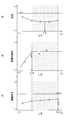
- each L / D value of the first nozzle hole 155a and the second nozzle hole 155b will be described in detail based on FIG.
- a pair of broken lines arranged with a solid line in between indicate the upper and lower limits of variation.
- each L / D value of each nozzle hole 155a, 155b in the first embodiment is defined such that the upper limit of the particle size causing the variation does not exceed a predetermined value.
- the L / D value is related to the contraction rate of the spray injected from the nozzle hole.
- the shrinkage rate of the spray indicates that the smaller the numerical value, the more difficult the spray shrinks and diffuses.
- the larger the L / D value the longer the flow path length of the nozzle hole, so that the fuel is rectified. Therefore, the spray sprayed becomes easy to be formed along the nozzle hole axis.
- the shrinkage rate of the spray increases as the L / D value increases.
- the shrinkage rate of the spray becomes almost constant when the L / D value exceeds a specific value.
- Each L / D value of each nozzle hole 155a, 155b in the first embodiment is defined to be 1.45 or more at which the increase in the spray shrinkage rate is saturated.
- each L / D value of each nozzle hole 155a, 155b of the first embodiment is defined to be 1.85 or less so that the spray length does not exceed a predetermined value.
- the predetermined value that defines the upper limit of the spray length is set such that the tip of the spray does not reach the cylinder wall surface and the piston top surface that define the combustion chamber.
- each L / D value of the first nozzle hole 155a and the second nozzle hole 155b is about 1.65 which is an intermediate value between the two boundary values (1.45, 1.85) described above. Are aligned. Therefore, even if the reference inner diameters Dn1 and Dn2 are different from each other, the atomization characteristics of the first injection hole 155a and the second injection hole 155b can be approximated to each other. Therefore, the fuel injection valve 10 can reduce the variation in the particle size of the spray injected from the injection holes 155a and 155b while forming a spray shape suitable for the fuel chamber of the internal combustion engine.
- the spray injected from each nozzle hole 155a, 155b is stably formed in the direction toward each nozzle hole axis 159a, 159b. According to the above, the rate of change of the spray injected from each nozzle hole 155a, 155b is close to each other and becomes a stable value. Therefore, the fuel injection valve 10 can stably form a spray having a shape suitable for the fuel chamber of the internal combustion engine.
- the fuel injection valve 10 can form a spray having a more optimal shape in the fuel chamber of the internal combustion engine.
- each flow path length Ln1, Ln2 can be defined so that each L / D value in each nozzle hole 155a, 155b is optimized.
- the configuration in which the respective diameter-enlarged holes 164 and 165 are provided to adjust the flow path lengths Ln1 and Ln2 is particularly suitable for the fuel injection valve 10 that optimizes the L / D values of the respective nozzle holes 155a and 155b. It is suitable.
- each of the enlarged diameter holes 164 and 165 is formed on the fuel downstream side of each of the injection holes 155a and 155b, the flow of the fuel to flow into each of the injection holes 155a and 155b is expanded. The situation of being disturbed in the diameter holes 164 and 165 can be avoided. Since the fuel in the sac chamber 154 can smoothly flow into the respective nozzle holes 155a and 155b, the shape of the spray injected from these nozzle holes 155a and 155b can be further stabilized.
- each of the enlarged diameter holes 164 and 165 is arranged coaxially with each of the injection holes 155a and 155b, the spray injected from each of the injection holes 155a and 155b It is formed without hitting the inner peripheral wall surface of 164,165. Therefore, a situation in which the shape of the spray is disturbed due to the formation of the respective enlarged diameter holes 164 and 165 is avoided.
- the bottom wall 160 corresponds to the “hole wall”.
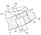
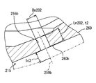
- the second embodiment of the present invention shown in FIGS. 7 to 9 is a modification of the first embodiment.
- a first injection hole 255a and a second injection hole 255b corresponding to the injection holes 155a and 155b (see FIG. 2) of the first embodiment are formed. Yes.
- a region that penetrates the first injection hole 255a is referred to as a first region 260a
- a region that penetrates the second injection hole 255b is referred to as a second region 260b.
- the bottom wall 260 does not have a configuration corresponding to the first enlarged hole 164 and the second enlarged hole 165 (see FIG. 2) of the first embodiment.
- the wall thicknesses of the first area 260a and the second area 260b are respectively set to the flow paths. It is defined to correspond to the lengths Ln201 and Ln202.
- the wall thicknesses t1 and t2 of the first region 260a and the second region 260b that are different from each other are adjusted by cutting the outer surface of the nozzle body 215 formed to have a substantially constant wall thickness.
- the thickness at which the nozzle body 215 is cut to form the second region 260b, rather than the thickness tc1 at which the nozzle body 215 is cut to form the first region 260a. tc2 is increased.
- the nozzle holes 255a and 255b having different channel lengths Ln201 and Ln202 are formed.
- the wall thicknesses t1 and t2 and the cutting thicknesses tc1 and tc2 are defined along the nozzle hole axes 259a and 259b.
- the same effects as those of the first embodiment can be obtained by aligning the L / D values of the first injection hole 255a and the second injection hole 255b within a predetermined range. Therefore, even if the reference inner diameters Dn201 and Dn202 of the respective nozzle holes 255a and 255b are different from each other, it is possible to approximate the characteristics of the sprays ejected therefrom.
- the flow path lengths Ln201 and Ln202 are made different by making the wall thicknesses t1 and t2 of the first region 260a and the second region 260b penetrating the nozzle holes 255a and 255b as in the second embodiment. The difference may be realized. With such a configuration, the feasibility of a configuration in which each L / D value is optimized further improves.
- the bottom wall 260 corresponds to an “injection hole wall”.
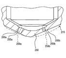
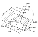
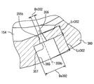
- the third embodiment of the present invention shown in FIGS. 10 and 11 is another modification of the first embodiment.
- a through hole made up of the first injection hole 355a and the first enlarged diameter hole 364 and a through hole made up of the second injection hole 355b and the second enlarged diameter hole 365 are formed.
- the first injection hole 355a and the second injection hole 355b are formed in tapered hole shapes that increase in diameter from the respective reference inner diameters Dn301 and Dn302 from the inlet side opening 356 toward the outlet side opening 357.
- the first diameter expansion hole 364 and the second diameter expansion hole 365 correspond to the diameter expansion holes 164 and 165 (see FIG. 4) of the first embodiment, and the injection hole axis lines 359a of the injection holes 355a and 355b. , 359b are arranged coaxially.
- the inner diameters De301 and De302 of the respective enlarged diameter holes 364 and 365 are larger than the respective reference inner diameters Dn301 and Dn302 of the respective injection holes 355a and 355b.
- the flow path length Le301 of the first diameter expansion hole 364 complements the difference between the flow path length Ln301 of the first injection hole 355a and the wall thickness of the bottom wall 360.
- the channel length Le302 of the second enlarged diameter hole 365 complements the difference between the channel length Ln302 of the second nozzle hole 355b and the wall thickness of the bottom wall 360.
- the atomization characteristics of the spray are related to the L / D value even if the nozzle hole has a tapered hole shape.
- the particle diameter of the spray in the tapered hole shape temporarily decreases as the L / D value decreases.
- the spray particle size gradually increases. This is presumably because the spray region formed into a liquid film is difficult to be formed because the flow path length is short. More specifically, in order to atomize the fuel, it is necessary to form a region in which the fuel is formed into a liquid film in the outer peripheral portion of the spray.
- each L / D value of each nozzle hole 355a, 355b in the third embodiment is defined so as to sandwich the above-mentioned L / D value indicating the minimum value.
- each L / D value of each nozzle hole 355a, 355b in the third embodiment is defined to be 2.0 or more at which the increase in the spray shrinkage rate is saturated.
- each L / D value of each nozzle hole 355a, 355b of the third embodiment is such that the minimum value shown in part (A) of FIG. 12 is sandwiched in the center together with the lower limit value shown in part (B) of FIG. For example, it is specified in 3.0.
- each L / D value of the first nozzle hole 355a and the second nozzle hole 355b is an intermediate value between the two boundary values (2.0, 3.0) described above, and is the most sprayed.
- the particle size is set to about 2.5.
- the L / D values of the two nozzle holes having different reference inner diameters are set to be the same.
- three or more nozzle holes having different reference inner diameters may not have the same L / D value.
- the L / D values of the nozzle holes do not have to be exactly the same, as long as they are set to be the same so that the spray characteristics can be approximated.
- each L / D value is defined within the range of the upper limit value and the lower limit value defined based on the shape of the nozzle hole.
- the L / D values of the nozzle holes may coincide with each other outside the range of the upper limit value and the lower limit value.
- each L / D value of each nozzle hole may be defined as a different value within the range of the upper limit value and the lower limit value.
- the plurality of nozzle holes are arranged along the same virtual circle 19 (see FIG. 3).
- the positions where the inlet openings of the plurality of nozzle holes are provided depend on the required spray shape. May be changed as appropriate.
- a small-diameter second nozzle hole may be arranged on the inner peripheral side of the large-diameter first nozzle hole.
- the first nozzle holes and the second nozzle holes may be alternately arranged in the circumferential direction.
- the shape of each nozzle hole may be changed as appropriate as long as the shapes are similar to each other.
- the taper angle of the inner wall surface may be changed as appropriate.
- the nozzle hole may be formed in a tapered hole shape whose diameter decreases from the inlet side opening toward the outlet side opening.
- the shape of the cross section of each nozzle hole may not be a perfect circle, but may be an ellipse or the like.
- the axial direction of the enlarged diameter hole was directed in the same direction as the nozzle hole axis.
- the axial direction of the diameter expansion hole may intersect the nozzle hole axis.
- the center of the diameter-expanded hole may be positioned so as to be shifted from the nozzle hole axis.
- the diameter expansion hole is not limited to the cylindrical hole shape as described above, and is a tapered hole shape whose diameter is increased toward the fuel downstream side, or a hemispherical shape in which the outer surface of the nozzle body is recessed. Also good.
- the diameter expansion hole may be provided in a form communicating with the sac chamber not on the fuel downstream side of the nozzle hole but on the fuel upstream side of the nozzle hole.
- the nozzle holes having different channel lengths are realized by changing the cutting thickness for cutting the outer surface of the nozzle body for each region.
- a radial step surface is not formed between the nozzle hole and the enlarged hole. Therefore, a situation in which deposits accumulate on the outer peripheral portion of the step surface can be avoided.
- the method of providing a difference between the wall thickness of the first region and the wall thickness of the second region in the nozzle body is not limited to the above-described cutting.
- a difference in wall thickness between the first region and the second region may already be provided when the nozzle body is molded.
- only the second region of the first region and the second region may be formed by cutting. Good.
Landscapes
- Engineering & Computer Science (AREA)
- Chemical & Material Sciences (AREA)
- Combustion & Propulsion (AREA)
- Mechanical Engineering (AREA)
- General Engineering & Computer Science (AREA)
- Fuel-Injection Apparatus (AREA)
Priority Applications (4)
| Application Number | Priority Date | Filing Date | Title |
|---|---|---|---|
| DE112014003551.3T DE112014003551T5 (de) | 2013-08-02 | 2014-07-29 | Kraftstoffinjektor |
| US14/909,265 US9828961B2 (en) | 2013-08-02 | 2014-07-29 | Fuel injector |
| CN201480043731.2A CN105473844A (zh) | 2013-08-02 | 2014-07-29 | 燃料喷射阀 |
| US15/792,788 US10260470B2 (en) | 2013-08-02 | 2017-10-25 | Fuel injector |
Applications Claiming Priority (2)
| Application Number | Priority Date | Filing Date | Title |
|---|---|---|---|
| JP2013161594A JP6020380B2 (ja) | 2013-08-02 | 2013-08-02 | 燃料噴射弁 |
| JP2013-161594 | 2013-08-02 |
Related Child Applications (2)
| Application Number | Title | Priority Date | Filing Date |
|---|---|---|---|
| US14/909,265 A-371-Of-International US9828961B2 (en) | 2013-08-02 | 2014-07-29 | Fuel injector |
| US15/792,788 Continuation US10260470B2 (en) | 2013-08-02 | 2017-10-25 | Fuel injector |
Publications (1)
| Publication Number | Publication Date |
|---|---|
| WO2015015797A1 true WO2015015797A1 (ja) | 2015-02-05 |
Family
ID=52431353
Family Applications (1)
| Application Number | Title | Priority Date | Filing Date |
|---|---|---|---|
| PCT/JP2014/003967 Ceased WO2015015797A1 (ja) | 2013-08-02 | 2014-07-29 | 燃料噴射弁 |
Country Status (5)
| Country | Link |
|---|---|
| US (2) | US9828961B2 (enExample) |
| JP (1) | JP6020380B2 (enExample) |
| CN (1) | CN105473844A (enExample) |
| DE (1) | DE112014003551T5 (enExample) |
| WO (1) | WO2015015797A1 (enExample) |
Cited By (2)
| Publication number | Priority date | Publication date | Assignee | Title |
|---|---|---|---|---|
| EP3173614A1 (de) * | 2015-11-26 | 2017-05-31 | Robert Bosch Gmbh | Düsenbaugruppe für einen kraftstoffinjektor sowie kraftstoffinjektor |
| US20220228545A1 (en) * | 2021-01-19 | 2022-07-21 | Honda Motor Co., Ltd. | Internal combustion engine |
Families Citing this family (12)
| Publication number | Priority date | Publication date | Assignee | Title |
|---|---|---|---|---|
| US9850869B2 (en) * | 2013-07-22 | 2017-12-26 | Delphi Technologies, Inc. | Fuel injector |
| JP6020380B2 (ja) | 2013-08-02 | 2016-11-02 | 株式会社デンソー | 燃料噴射弁 |
| JP6292188B2 (ja) * | 2015-04-09 | 2018-03-14 | 株式会社デンソー | 燃料噴射装置 |
| JP2017036678A (ja) * | 2015-08-07 | 2017-02-16 | 日立オートモティブシステムズ株式会社 | 電磁式弁 |
| JP2018040314A (ja) * | 2016-09-08 | 2018-03-15 | いすゞ自動車株式会社 | 燃料噴射ノズル |
| US20190056109A1 (en) * | 2017-08-21 | 2019-02-21 | General Electric Company | Main fuel nozzle for combustion dynamics attenuation |
| JP2020008013A (ja) * | 2018-07-12 | 2020-01-16 | 株式会社Soken | 燃料噴射弁 |
| GB2577251A (en) * | 2018-09-18 | 2020-03-25 | Ford Global Tech Llc | Diesel injectors and method of manufacturing diesel injectors |
| JP2019124226A (ja) * | 2019-05-10 | 2019-07-25 | 日立オートモティブシステムズ株式会社 | 燃料噴射弁 |
| US11073071B2 (en) * | 2019-07-23 | 2021-07-27 | Ford Global Technologies, Llc | Fuel injector with divided flowpath nozzle |
| WO2022064766A1 (ja) * | 2020-09-24 | 2022-03-31 | 日立Astemo株式会社 | 燃料噴射装置 |
| CN117460884A (zh) | 2021-06-11 | 2024-01-26 | 康明斯有限公司 | 用于在燃料系统和发动机部件中硬加工孔口的方法和设备 |
Citations (7)
| Publication number | Priority date | Publication date | Assignee | Title |
|---|---|---|---|---|
| JPH01208563A (ja) * | 1988-02-12 | 1989-08-22 | Hitachi Ltd | 燃料噴射弁 |
| JP2000073917A (ja) * | 1998-08-26 | 2000-03-07 | Man B & W Diesel Gmbh | 内燃機関用燃料噴射ノズル |
| JP2004076723A (ja) * | 2002-06-20 | 2004-03-11 | Denso Corp | 燃料噴射装置 |
| JP2004204808A (ja) * | 2002-12-26 | 2004-07-22 | Yanmar Co Ltd | 燃料噴射ノズル |
| JP2009209742A (ja) * | 2008-03-03 | 2009-09-17 | Yanmar Co Ltd | 多噴口燃料噴射ノズル |
| JP2010164060A (ja) * | 2008-03-27 | 2010-07-29 | Denso Corp | 燃料噴射弁 |
| JP2012246897A (ja) * | 2011-05-31 | 2012-12-13 | Denso Corp | 燃料噴射装置 |
Family Cites Families (21)
| Publication number | Priority date | Publication date | Assignee | Title |
|---|---|---|---|---|
| JPS58148967A (ja) | 1982-03-02 | 1983-09-05 | Toshiba Corp | プロセス状態量を推定する際のバツクアツプ方法 |
| JP2819702B2 (ja) * | 1989-12-12 | 1998-11-05 | 株式会社デンソー | 燃料噴射弁 |
| JP3193734B2 (ja) | 1991-07-15 | 2001-07-30 | 松下電工株式会社 | 可変色照明システム |
| US6644565B2 (en) * | 1998-10-15 | 2003-11-11 | Robert Bosch Gmbh | Fuel injection nozzle for self-igniting internal combustion engines |
| DE19937961A1 (de) * | 1999-08-11 | 2001-02-15 | Bosch Gmbh Robert | Brennstoffeinspritzventil und Verfahren zur Herstellung von Austrittsöffnungen an Ventilen |
| US6708905B2 (en) * | 1999-12-03 | 2004-03-23 | Emissions Control Technology, Llc | Supersonic injector for gaseous fuel engine |
| US6422198B1 (en) * | 2000-09-19 | 2002-07-23 | Delphi Technologies, Inc. | Pressure atomizer having multiple orifices and turbulent generation feature |
| DE10118163B4 (de) * | 2001-04-11 | 2007-04-19 | Robert Bosch Gmbh | Brennstoffeinspritzventil |
| DE10319694A1 (de) * | 2003-05-02 | 2004-12-02 | Robert Bosch Gmbh | Brennstoffeinspritzventil |
| DE102005036951A1 (de) * | 2005-08-05 | 2007-02-08 | Robert Bosch Gmbh | Brennstoffeinspritzventil und Verfahren zur Ausformung von Abspritzöffnungen |
| JP4528701B2 (ja) * | 2005-09-13 | 2010-08-18 | 日立オートモティブシステムズ株式会社 | 噴射弁及びオリフィスの加工方法 |
| JP2008202483A (ja) | 2007-02-20 | 2008-09-04 | Hitachi Ltd | 筒内噴射型の内燃機関、及び筒内噴射型の内燃機関に用いるインジェクタ |
| GB0712403D0 (en) * | 2007-06-26 | 2007-08-01 | Delphi Tech Inc | A Spray Hole Profile |
| JP4985661B2 (ja) | 2008-03-27 | 2012-07-25 | 株式会社デンソー | 燃料噴射弁 |
| JP4627783B2 (ja) * | 2008-03-31 | 2011-02-09 | 日立オートモティブシステムズ株式会社 | 燃料噴射弁及びオリフィスの加工方法 |
| JP5033735B2 (ja) | 2008-08-08 | 2012-09-26 | 日立オートモティブシステムズ株式会社 | ノズルの加工方法 |
| CN101737217A (zh) * | 2008-11-13 | 2010-06-16 | 福特环球技术公司 | 带有喷嘴的火花点火内燃发动机 |
| JP5959892B2 (ja) * | 2012-03-26 | 2016-08-02 | 日立オートモティブシステムズ株式会社 | 火花点火式燃料噴射弁 |
| DE102012209326A1 (de) * | 2012-06-01 | 2013-12-05 | Robert Bosch Gmbh | Brennstoffeinspritzventil |
| JP6186130B2 (ja) * | 2013-02-04 | 2017-08-23 | 日立オートモティブシステムズ株式会社 | 燃料噴射弁及び燃料噴射弁の製造方法 |
| JP6020380B2 (ja) | 2013-08-02 | 2016-11-02 | 株式会社デンソー | 燃料噴射弁 |
-
2013
- 2013-08-02 JP JP2013161594A patent/JP6020380B2/ja active Active
-
2014
- 2014-07-29 CN CN201480043731.2A patent/CN105473844A/zh active Pending
- 2014-07-29 DE DE112014003551.3T patent/DE112014003551T5/de active Pending
- 2014-07-29 US US14/909,265 patent/US9828961B2/en active Active
- 2014-07-29 WO PCT/JP2014/003967 patent/WO2015015797A1/ja not_active Ceased
-
2017
- 2017-10-25 US US15/792,788 patent/US10260470B2/en active Active
Patent Citations (7)
| Publication number | Priority date | Publication date | Assignee | Title |
|---|---|---|---|---|
| JPH01208563A (ja) * | 1988-02-12 | 1989-08-22 | Hitachi Ltd | 燃料噴射弁 |
| JP2000073917A (ja) * | 1998-08-26 | 2000-03-07 | Man B & W Diesel Gmbh | 内燃機関用燃料噴射ノズル |
| JP2004076723A (ja) * | 2002-06-20 | 2004-03-11 | Denso Corp | 燃料噴射装置 |
| JP2004204808A (ja) * | 2002-12-26 | 2004-07-22 | Yanmar Co Ltd | 燃料噴射ノズル |
| JP2009209742A (ja) * | 2008-03-03 | 2009-09-17 | Yanmar Co Ltd | 多噴口燃料噴射ノズル |
| JP2010164060A (ja) * | 2008-03-27 | 2010-07-29 | Denso Corp | 燃料噴射弁 |
| JP2012246897A (ja) * | 2011-05-31 | 2012-12-13 | Denso Corp | 燃料噴射装置 |
Cited By (3)
| Publication number | Priority date | Publication date | Assignee | Title |
|---|---|---|---|---|
| EP3173614A1 (de) * | 2015-11-26 | 2017-05-31 | Robert Bosch Gmbh | Düsenbaugruppe für einen kraftstoffinjektor sowie kraftstoffinjektor |
| US20220228545A1 (en) * | 2021-01-19 | 2022-07-21 | Honda Motor Co., Ltd. | Internal combustion engine |
| US11530672B2 (en) * | 2021-01-19 | 2022-12-20 | Honda Motor Co., Ltd. | Internal combustion engine |
Also Published As
| Publication number | Publication date |
|---|---|
| US10260470B2 (en) | 2019-04-16 |
| CN105473844A (zh) | 2016-04-06 |
| JP2015031212A (ja) | 2015-02-16 |
| DE112014003551T5 (de) | 2016-05-12 |
| JP6020380B2 (ja) | 2016-11-02 |
| US9828961B2 (en) | 2017-11-28 |
| US20180045157A1 (en) | 2018-02-15 |
| US20160195052A1 (en) | 2016-07-07 |
Similar Documents
| Publication | Publication Date | Title |
|---|---|---|
| JP6020380B2 (ja) | 燃料噴射弁 | |
| JP5312148B2 (ja) | 燃料噴射弁 | |
| JP6166168B2 (ja) | 燃料噴射弁 | |
| CN103282644A (zh) | 喷射阀 | |
| US8919674B2 (en) | Fuel injection valve | |
| JP2013068125A (ja) | 燃料噴射弁 | |
| US11493009B2 (en) | Fuel injection valve and fuel injection system | |
| JP2017025926A (ja) | 燃料噴射弁 | |
| JP2015025406A (ja) | 燃料噴射弁 | |
| JP2009250122A (ja) | 燃料噴射弁 | |
| JP6268185B2 (ja) | 燃料噴射弁 | |
| JP4129688B2 (ja) | 流体噴射弁 | |
| US20190277236A1 (en) | Fuel injection valve and fuel injection system | |
| JP5716788B2 (ja) | 燃料噴射弁 | |
| JP5983795B2 (ja) | 燃料噴射弁 | |
| US10724487B2 (en) | Fuel injection valve and fuel injection system | |
| JP3130439B2 (ja) | 流体噴射ノズル | |
| JP2017031980A (ja) | 燃料噴射弁 | |
| JP6024817B2 (ja) | 燃料噴射弁 | |
| WO2021075041A1 (ja) | 燃料噴射弁 | |
| JP4511960B2 (ja) | 燃料噴射弁 | |
| JP2015101978A (ja) | 燃料噴射弁 | |
| JP2011127487A (ja) | 燃料噴射弁 | |
| CN111356835B (zh) | 燃料喷射阀 | |
| JP2007303442A (ja) | 燃料噴射弁 |
Legal Events
| Date | Code | Title | Description |
|---|---|---|---|
| WWE | Wipo information: entry into national phase |
Ref document number: 201480043731.2 Country of ref document: CN |
|
| 121 | Ep: the epo has been informed by wipo that ep was designated in this application |
Ref document number: 14831398 Country of ref document: EP Kind code of ref document: A1 |
|
| WWE | Wipo information: entry into national phase |
Ref document number: 14909265 Country of ref document: US |
|
| WWE | Wipo information: entry into national phase |
Ref document number: 112014003551 Country of ref document: DE |
|
| 122 | Ep: pct application non-entry in european phase |
Ref document number: 14831398 Country of ref document: EP Kind code of ref document: A1 |