WO2014203587A1 - 基板保持回転装置およびそれを備えた基板処理装置、ならびに基板処理方法 - Google Patents
基板保持回転装置およびそれを備えた基板処理装置、ならびに基板処理方法 Download PDFInfo
- Publication number
- WO2014203587A1 WO2014203587A1 PCT/JP2014/059396 JP2014059396W WO2014203587A1 WO 2014203587 A1 WO2014203587 A1 WO 2014203587A1 JP 2014059396 W JP2014059396 W JP 2014059396W WO 2014203587 A1 WO2014203587 A1 WO 2014203587A1
- Authority
- WO
- WIPO (PCT)
- Prior art keywords
- substrate
- holding
- turntable
- disk
- protective disk
- Prior art date
- Legal status (The legal status is an assumption and is not a legal conclusion. Google has not performed a legal analysis and makes no representation as to the accuracy of the status listed.)
- Ceased
Links
Images






Classifications
-
- B—PERFORMING OPERATIONS; TRANSPORTING
- B08—CLEANING
- B08B—CLEANING IN GENERAL; PREVENTION OF FOULING IN GENERAL
- B08B3/00—Cleaning by methods involving the use or presence of liquid or steam
- B08B3/02—Cleaning by the force of jets or sprays
-
- H—ELECTRICITY
- H10—SEMICONDUCTOR DEVICES; ELECTRIC SOLID-STATE DEVICES NOT OTHERWISE PROVIDED FOR
- H10P—GENERIC PROCESSES OR APPARATUS FOR THE MANUFACTURE OR TREATMENT OF DEVICES COVERED BY CLASS H10
- H10P72/00—Handling or holding of wafers, substrates or devices during manufacture or treatment thereof
- H10P72/04—Apparatus for manufacture or treatment
- H10P72/0402—Apparatus for fluid treatment
- H10P72/0406—Apparatus for fluid treatment for cleaning followed by drying, rinsing, stripping, blasting or the like
- H10P72/0411—Apparatus for fluid treatment for cleaning followed by drying, rinsing, stripping, blasting or the like for wet cleaning or washing
- H10P72/0412—Apparatus for fluid treatment for cleaning followed by drying, rinsing, stripping, blasting or the like for wet cleaning or washing using mainly scrubbing means, e.g. brushes
-
- B—PERFORMING OPERATIONS; TRANSPORTING
- B08—CLEANING
- B08B—CLEANING IN GENERAL; PREVENTION OF FOULING IN GENERAL
- B08B3/00—Cleaning by methods involving the use or presence of liquid or steam
- B08B3/04—Cleaning involving contact with liquid
- B08B3/10—Cleaning involving contact with liquid with additional treatment of the liquid or of the object being cleaned, e.g. by heat, by electricity or by vibration
-
- H—ELECTRICITY
- H10—SEMICONDUCTOR DEVICES; ELECTRIC SOLID-STATE DEVICES NOT OTHERWISE PROVIDED FOR
- H10P—GENERIC PROCESSES OR APPARATUS FOR THE MANUFACTURE OR TREATMENT OF DEVICES COVERED BY CLASS H10
- H10P70/00—Cleaning of wafers, substrates or parts of devices
- H10P70/10—Cleaning before device manufacture, i.e. Begin-Of-Line process
- H10P70/15—Cleaning before device manufacture, i.e. Begin-Of-Line process by wet cleaning only
-
- H—ELECTRICITY
- H10—SEMICONDUCTOR DEVICES; ELECTRIC SOLID-STATE DEVICES NOT OTHERWISE PROVIDED FOR
- H10P—GENERIC PROCESSES OR APPARATUS FOR THE MANUFACTURE OR TREATMENT OF DEVICES COVERED BY CLASS H10
- H10P72/00—Handling or holding of wafers, substrates or devices during manufacture or treatment thereof
- H10P72/04—Apparatus for manufacture or treatment
- H10P72/0402—Apparatus for fluid treatment
- H10P72/0404—Apparatus for fluid treatment for general liquid treatment, e.g. etching followed by cleaning
-
- H—ELECTRICITY
- H10—SEMICONDUCTOR DEVICES; ELECTRIC SOLID-STATE DEVICES NOT OTHERWISE PROVIDED FOR
- H10P—GENERIC PROCESSES OR APPARATUS FOR THE MANUFACTURE OR TREATMENT OF DEVICES COVERED BY CLASS H10
- H10P72/00—Handling or holding of wafers, substrates or devices during manufacture or treatment thereof
- H10P72/04—Apparatus for manufacture or treatment
- H10P72/0402—Apparatus for fluid treatment
- H10P72/0406—Apparatus for fluid treatment for cleaning followed by drying, rinsing, stripping, blasting or the like
- H10P72/0411—Apparatus for fluid treatment for cleaning followed by drying, rinsing, stripping, blasting or the like for wet cleaning or washing
- H10P72/0414—Apparatus for fluid treatment for cleaning followed by drying, rinsing, stripping, blasting or the like for wet cleaning or washing using mainly spraying means, e.g. nozzles
-
- H—ELECTRICITY
- H10—SEMICONDUCTOR DEVICES; ELECTRIC SOLID-STATE DEVICES NOT OTHERWISE PROVIDED FOR
- H10P—GENERIC PROCESSES OR APPARATUS FOR THE MANUFACTURE OR TREATMENT OF DEVICES COVERED BY CLASS H10
- H10P72/00—Handling or holding of wafers, substrates or devices during manufacture or treatment thereof
- H10P72/70—Handling or holding of wafers, substrates or devices during manufacture or treatment thereof for supporting or gripping
- H10P72/76—Handling or holding of wafers, substrates or devices during manufacture or treatment thereof for supporting or gripping using mechanical means, e.g. clamps or pinches
- H10P72/7604—Handling or holding of wafers, substrates or devices during manufacture or treatment thereof for supporting or gripping using mechanical means, e.g. clamps or pinches the wafers being placed on a susceptor, stage or support
- H10P72/7608—Handling or holding of wafers, substrates or devices during manufacture or treatment thereof for supporting or gripping using mechanical means, e.g. clamps or pinches the wafers being placed on a susceptor, stage or support characterised by a plurality of separate clamping members, e.g. clamping fingers
-
- H—ELECTRICITY
- H10—SEMICONDUCTOR DEVICES; ELECTRIC SOLID-STATE DEVICES NOT OTHERWISE PROVIDED FOR
- H10P—GENERIC PROCESSES OR APPARATUS FOR THE MANUFACTURE OR TREATMENT OF DEVICES COVERED BY CLASS H10
- H10P72/00—Handling or holding of wafers, substrates or devices during manufacture or treatment thereof
- H10P72/70—Handling or holding of wafers, substrates or devices during manufacture or treatment thereof for supporting or gripping
- H10P72/76—Handling or holding of wafers, substrates or devices during manufacture or treatment thereof for supporting or gripping using mechanical means, e.g. clamps or pinches
- H10P72/7604—Handling or holding of wafers, substrates or devices during manufacture or treatment thereof for supporting or gripping using mechanical means, e.g. clamps or pinches the wafers being placed on a susceptor, stage or support
- H10P72/7626—Handling or holding of wafers, substrates or devices during manufacture or treatment thereof for supporting or gripping using mechanical means, e.g. clamps or pinches the wafers being placed on a susceptor, stage or support characterised by the construction of the shaft
Definitions
- the present invention relates to a substrate holding and rotating apparatus, a substrate processing apparatus including the same, and a substrate processing method.
- substrates to be held or processed include semiconductor wafers, liquid crystal display substrates, plasma display substrates, FED (Field Emission Display) substrates, optical disk substrates, magnetic disk substrates, magneto-optical disk substrates, Photomask substrates, ceramic substrates, solar cell substrates and the like are included.
- Patent Document 1 discloses a rotary substrate processing apparatus including a rotary table rotated by a rotary unit, and a support unit that is disposed on the rotary table and horizontally positions a substrate at a predetermined interval from the surface of the rotary table.
- a substrate rotating holder is disclosed.
- On the turntable a vertically moving member having the same size as the substrate is provided, and the vertically moving member is disposed at a raised position near the substrate during the process of rotating the turntable.
- FIGS. 1 to 3 of Patent Document 1 The configuration shown in FIGS. 1 to 3 of Patent Document 1 is configured so that the vertically moving member is moved up and down with respect to the turntable by a push-up mechanism that operates by receiving the centrifugal force accompanying the rotation of the turntable. Yes. Further, in FIGS. 7 and 8 of Patent Document 1, fins are provided on the outer peripheral portion of the vertical movement member, and when the vertical movement member rotates with the rotation of the turntable, the fin pushes down the surrounding gas downward.
- the structure which lifts an up-and-down moving member using the lift which arises by this is disclosed.
- FIG. 9 and FIG. 10 of Patent Document 1 disclose a configuration in which the vertically moving member is moved up and down using a push-up mechanism using an air cylinder. Further, in FIGS. 11 and 12 of Patent Document 1, a bellows having one end fixed to a vertically moving member is provided, and the bellows is expanded and contracted by pressurizing / sucking the inside of the bellows, thereby moving the vertically moving member up and down. The configuration to be shown is shown.
- both of these configurations have a structure in which a driving means for driving up and down is incorporated in a rotating system including a turntable and a vertically moving member, and it is necessary to supply driving force to the driving means. Becomes complicated.
- a driving means for driving up and down is incorporated in a rotating system including a turntable and a vertically moving member, and it is necessary to supply driving force to the driving means.
- since it is necessary to supply or suck air for driving from the non-rotating system there is a sliding portion that frictionally contacts the air supply / suction path between the non-rotating system and the rotating system. As a result, there is a possibility that particles generated therefrom have an adverse effect on the substrate processing.
- An object of the present invention is to provide a substrate holding and rotating device that can protect the lower surface of a substrate regardless of the rotation speed of the substrate, has a simple configuration, and can suppress generation of particles due to frictional contact, And it is providing the substrate processing apparatus provided with such a substrate holding
- maintenance rotation apparatus. Another object of the present invention is to reliably protect the lower surface of the substrate even when the rotation speed of the substrate is low, without requiring a complicated configuration, and suppressing particles caused by frictional contact. To provide a substrate processing method capable of realizing high-quality processing.
- An embodiment of the present invention includes a turntable that is rotatable about a rotation axis along a vertical direction, a rotation drive unit that rotates the turntable, and the turntable that rotates about the rotation axis together with the turntable.
- a rotation drive unit that rotates the turntable
- the turntable that rotates about the rotation axis together with the turntable.
- a magnetic levitation mechanism that has an opening surrounding the entire circumference of the holding member and that is larger than the substrate held by the holding member, and that floats the protective disk from the turntable
- a magnetic holding mechanism for holding the holding member at the holding position.
- the protective disk is disposed between the turntable and a substrate holding position by the holding member, and has a lower position and an approach position approaching the lower surface of the substrate held by the holding member above the lower position. It can be moved up and down relatively with respect to the turntable, and is attached to the turntable so as to rotate around the rotation axis together with the turntable.
- the magnetic levitation mechanism includes a first magnet attached to the protection disk, a second magnet that is formed in an annular shape coaxial with the rotation axis and that gives a repulsive force to the first magnet, and a second magnet that A first support member for supporting in a rotating state, and a first relative movement mechanism for relatively moving the first support member and the turntable so that a distance between the first magnet and the second magnet changes.
- the protection disk is configured to float from the turntable by a repulsive force between the first magnet and the second magnet.
- the magnetic drive mechanism includes a first magnetic body attached to the holding member, a second magnetic body formed in an annular shape coaxial with the rotation axis and generating a magnetic force between the first magnetic body, and the second The second support member that supports the magnetic body in a non-rotating state, and the second support member and the turntable are relatively moved so that the distance between the first magnetic body and the second magnetic body changes. And a second relative movement mechanism that is different from the first relative movement mechanism, and holds the holding member at the holding position by a magnetic force between the first magnetic body and the second magnetic body.
- the rotating table rotated by the rotation drive unit is provided with the holding member, and the holding member can hold the substrate horizontally in a state of being spaced upward from the rotating table.
- a protection disk for protecting the lower surface of the substrate is attached to the turntable, and this protection disk can move up and down relatively with respect to the turntable. That is, the protective disk can move up and down relatively with respect to the turntable between a lower position and an approach position approaching the lower surface of the substrate held by the holding member above the lower position.
- a magnetic levitation mechanism is provided in order to drive the protection disk. That is, the magnetic levitation mechanism includes a first magnet that relatively moves the first magnet attached to the protective disk, the second magnet supported by the first support member in a non-rotating state, and the first support member and the turntable. A moving mechanism.
- the first support member and the turntable are moved relative to each other, and the second magnet is disposed at a sufficiently close position below the first magnet. It can be levitated from the turntable, guided to the approach position, and held at the approach position.
- the transmission of the driving force from the non-rotating system to the rotating system is performed in a non-contact manner by utilizing the repulsive magnetic force acting between the second magnet provided in the non-rotating system and the first magnet provided in the rotating system. Achieved. Therefore, in addition to the simple structure, even when the turntable is rotating and the first magnet attached to the protection disk is rotating accordingly, the driving force transmitted in a non-contact state, The protective disk can be held in the approach position.
- the protective disk can be sufficiently brought close to the lower surface of the substrate.
- the lower surface of the substrate can be surely protected regardless of the rotation speed of the substrate, the configuration is simple, and the substrate holding and rotating device that suppresses particles caused by frictional contact that occurs during rotation. Can be provided.
- the holding member is brought into the holding position in a non-contact state. Can be held. Therefore, the configuration for holding the holding member in the holding position is also simple. In addition, since the driving force for holding the holding member in the holding position can be transmitted in a non-contact state due to the magnetic force, generation of particles due to frictional contact during rotation can be further suppressed.
- the second magnetic body is formed in an annular shape coaxial with the rotation axis, even when the first magnetic body rotates together with the turntable, the first magnetic body and the second magnetic body are located at any rotational position. Therefore, the holding member can be reliably held at the holding position, thereby ensuring the holding of the substrate.
- Protective disk is placed below the substrate and protects the bottom surface of the substrate from below.
- the outer diameter of the protective disk is larger than the diameter of the substrate.
- the protective disk can protect a wider area of the substrate than if the outer diameter of the protective disk is less than or equal to the diameter of the substrate.
- the contamination of the substrate due to the adhesion of particles can be more reliably suppressed or prevented.
- the airflow flowing outward between the protective disk and the turntable is reliably guided to the outside by the protective disk, it flows upward from between the outer periphery of the protective disk and the outer periphery of the turntable. Even if an air flow is generated, this air flow is unlikely to contact the peripheral edge of the substrate. Therefore, it is possible to suppress or prevent the substrate from being contaminated by particles contained in the airflow.
- the outer peripheral surface of the protective disk is arranged outward from the holding member.
- the holding member rotates with the substrate by the rotation of the turntable, the air current is disturbed by the holding member.
- the holding member is disposed outward from the outer peripheral surface of the protective disk, the turbulence of the airflow affects the atmosphere around the substrate and may cause adhesion of foreign matters such as particles.
- the holding member is disposed inward from the outer peripheral surface of the protective disk, the turbulence of the airflow by the holding member is suppressed by the protective disk, and as a result, contamination of the substrate can be suppressed or prevented.
- the protective disk When the protective disk is in the lower position, a space is formed between the protective disk and the lower surface of the substrate. By using this space, the substrate is transferred from the substrate transfer robot to the holding member, or the substrate is transferred. The robot can receive the substrate from the holding member.
- the second magnet has a magnetic pole formed in an annular shape coaxial with the rotation axis. More specifically, it is preferable that the second magnet has a ring-shaped magnetic pole corresponding to the rotation locus drawn by the first magnet. Thereby, even when the first magnet rotates together with the turntable, the repulsive force between the first magnet and the second magnet acts continuously and stably, so that the protective disk can be reliably held at the approach position. .
- the first relative movement mechanism may be a mechanism that moves the first support member up and down, a mechanism that moves the turntable up and down, or the first support member and the turntable. It may be a mechanism that moves both up and down.
- the first relative movement mechanism is not necessarily a mechanism that relatively moves the first support member and the turntable up and down, and causes the second magnet to approach the first magnet from the direction intersecting the rotation axis. Therefore, a repulsive force may be applied between them.
- one or both of the first magnetic body and the second magnetic body is a magnet.
- the second relative movement mechanism may be a mechanism that moves the second support member up and down, a mechanism that moves the turntable up and down, or the second support member and the turntable. It may be a mechanism that moves both up and down.
- the second relative movement mechanism is not limited to a mechanism that moves the second support member and / or the turntable up and down. For example, the second support member is moved in a direction crossing the rotation axis, thereby causing the second support member and / or the turntable to move up and down. It may be a mechanism for moving the magnetic body toward / separating from the first magnetic body.
- the second magnetic body is the second magnet
- the second support member is the first support member
- the second relative movement mechanism is the first relative movement mechanism.
- the magnetic drive mechanism and the magnetic levitation mechanism share the second magnet, the first support member, and the first relative movement mechanism, and when the second magnet is in a predetermined position, the second magnet
- the protective disk is held at the approach position by a repulsive force between the magnet and the first magnet, and the holding member is moved to the holding position by a magnetic force acting between the second magnet and the first magnetic body. It is also conceivable to be retained.
- the magnetic drive mechanism and the magnetic levitation mechanism share the second magnet, the first support member, and the first relative movement mechanism.
- the protective disk By moving the support member relative to each other, the protective disk can be driven and the holding member can be driven.
- the configuration can be further simplified.
- a restriction member may be further included for restricting the upward relative movement of the protection disk with respect to the turntable at the approach position.
- the protective disk since the upward relative movement of the protective disk that is levitated by the magnetic force can be restricted by the restriction member, the protective disk can be reliably disposed at an approach position close to the lower surface of the substrate.
- the approach position is a position where the protective disk does not come into contact with the lower surface of the substrate and is spaced from the lower surface of the substrate, the minute interval can be maintained.
- the substrate holding and rotating device may further include a guide mechanism that is provided on the turntable and guides the relative vertical movement of the protective disk. With this configuration, the relative vertical movement of the protective disk with respect to the turntable can be stabilized.
- the protective disk may include a side cover that covers a space between the substrate held by the holding member and the turntable from the side. According to this structure, since the space between a turntable and a board
- the side cover is fixed to the protective disk (a disk body larger than the substrate).
- the space between the protection disk and the turntable is covered by the side cover portion in a state where the protection disk is disposed at the approach position.
- the protective disk is in the lower position, the side of the space between the protective disk and the lower surface of the substrate is opened, and this space can be used for loading / unloading the substrate. Is preferred.
- the substrate holding and rotating device supplies an inert gas between the substrate held and rotated by the holding member and the protective disk disposed at the approach position.
- a supply unit may be further included. According to this configuration, since the inert gas is supplied between the protective disk and the substrate, it is possible to more effectively suppress the treatment liquid mist from adhering to the lower surface of the substrate.
- the upper surface of the protective disk includes a facing portion disposed below a substrate held by the holding member, an inward portion extending upward from an outer periphery of the facing portion, and the inward direction. And an outer peripheral portion extending outward from the upper end of the portion.
- the upper surface of the protective disk may be formed by the inward portion and the outer peripheral portion at the edge portion of the substrate held by the holding member to restrict the flow path of the inert gas. . According to this configuration, since the flow path of the inert gas is narrowed at the edge portion of the substrate, the flow rate of the inert gas around the substrate is increased. Thereby, it is possible to more effectively suppress the processing liquid mist from entering the space between the protective disk and the lower surface of the substrate.
- the upper surface of the protection disk includes a facing portion disposed below the substrate held by the holding member, and an inward portion extending upward from an outer periphery of the facing portion, and the throttle portion is directed inwardly You may form by the part.
- the outer peripheral portion extending outward from the upper end of the inward portion may be omitted, and only the inward portion may form the throttle portion.
- the inert gas supply unit includes an inert gas nozzle that blows out an inert gas radially from the rotation center of the turntable toward the peripheral edge of the substrate held by the holding member. May be.
- the inert gas is blown radially from the inert gas nozzle, so that in the space between the protective disk and the lower surface of the substrate, the inert gas from the rotation center of the turntable toward the peripheral edge of the substrate. Stable flow can be formed. Thereby, the approach of the process liquid mist to the said space can be suppressed more effectively.
- the substrate holding and rotating device may further include a height sensor that detects a height of the protective disk between the lower position and the approach position.
- the height sensor may be a direct sensor that directly detects the height of the protective disk, or by detecting the height of an interlocking member that moves in the vertical direction together with the protective disk. It may be an indirect sensor that indirectly detects the height.
- the height sensor may be a non-contact sensor that detects the height of the protection disk in a non-contact manner with respect to the detection object (the protection disk or the interlocking member), or in a state of being in contact with the detection object. It may be a contact sensor that detects the height of the protective disk.
- the height sensor detects the height of the interlocking member that moves in the vertical direction together with the protective disk, the height sensor does not have to be disposed in the vicinity of the protective disk. Is expensive.
- Another embodiment of the present invention provides a substrate processing apparatus including the substrate holding and rotating apparatus described above and a processing liquid supply unit that supplies a processing liquid to the upper surface of the substrate held by the substrate holding and rotating apparatus.
- the processing liquid is supplied to the upper surface of the substrate with the lower surface of the substrate covered with the protective disk, and the upper surface of the substrate can be processed with the processing liquid. Therefore, even if mist of the processing liquid is generated, it is possible to suppress the mist from reaching the lower surface of the substrate. As a result, it is possible to selectively perform the processing on the upper surface of the substrate without supplying the processing liquid to the lower surface of the substrate and holding the lower surface of the substrate in a clean state. More specifically, the lower surface of the substrate can be kept dry, and the upper surface of the substrate can be treated with the processing liquid without causing contamination of the lower surface of the substrate.
- the substrate holding and rotating device can protect the lower surface of the substrate reliably by holding the protective disk in the approaching position even when the rotation of the substrate is stopped or at a low speed, and the structure is simple, and when rotating There is little generation of particles due to sliding. Accordingly, the upper surface of the substrate can be selectively processed using the processing liquid in a clean environment that suppresses the adhesion of mist to the lower surface of the substrate and generates less particles without requiring a complicated configuration.
- the substrate processing apparatus is supplied from the processing liquid supply unit to the substrate held by the substrate holding and rotating device, and is discharged from the upper surface of the substrate to the outside of the substrate.
- a receiving member for receiving the treatment liquid may be further included.
- the second support member may be fixed to the receiving member, and the second relative movement mechanism may be configured to relatively move the receiving member and the turntable.
- the first support member that supports the second magnet is moved as a mechanism for relatively moving the receiving member that receives the processing liquid discharged from the upper surface of the substrate to the outside of the substrate and the turntable.
- the configuration can be further simplified.
- the relative position between the receiving member and the turntable is the processing position where the processing liquid discharged from the upper surface of the substrate is received by the receiving member, the repulsion between the first and second magnets.
- the protective disk is configured to be held in the approach position by force.
- the first magnetic body receives the magnetic force from the second magnet at the processing position, and the holding member is held at the holding position.
- Still another embodiment of the present invention is provided on a turntable rotatable around a rotation axis along the vertical direction, and is displaceable between a holding position for holding a substrate and a retracted position retracted from the holding position.
- a protective disk larger than the substrate having an opening surrounding the entire circumference of the holding member is attached to a first magnet attached to the protective disk and an annular shape provided in a non-rotating state coaxially with the rotation axis
- the rotating step includes a treatment liquid supply step of supplying a processing liquid to the upper surface of the substrate lower surface is covered with the protective disc, to provide a substrate processing method.
- the holding step is a step of holding the holding member at the holding position by applying a magnetic force from a second magnetic body different from the second magnet to the first magnetic body attached to the holding member.
- the processing liquid it is possible to supply the processing liquid to the upper surface of the substrate while rotating the substrate while covering the lower surface of the substrate with the protective disk attached to the turntable, and to process the upper surface of the substrate with the processing liquid.
- the protection disk floats to an approaching position close to the lower surface of the substrate by a repulsive force acting between the first magnet attached to the protection disk and the annular second magnet provided in a non-rotating state. Retained. Therefore, even when the substrate is stopped or when the rotation of the substrate is slow, the protective disk can be reliably brought close to the lower surface of the substrate, and adhesion of the processing liquid mist to the lower surface of the substrate can be reliably suppressed.
- the protection disk is floated and held using the repulsive force between the first magnet and the second magnet, it is not necessary to provide a drive unit for moving the protection disk up and down in the rotating system. Therefore, the protective disk can be brought close to the lower surface of the substrate when necessary without complicating the configuration. Further, since the first magnet and the second magnet can transmit a repulsive force in a non-contact state, generation of particles due to frictional contact during rotation can be suppressed.
- the holding member provided in the turntable is held at the holding position using magnetic force, the holding force can be transmitted to the holding member in a non-contact state. Therefore, the upper surface of the substrate can be selectively processed with a simpler structure, and generation of particles due to frictional contact during rotation can be further suppressed.
- the lower surface covering step causes the protective disk to float to the approach position by a repulsive force between the second magnet and the first magnet by disposing the second magnet at a predetermined position. And holding the holding member at the holding position by the magnetic force acting between the second magnet and the magnetic body by disposing the second magnet at the predetermined position. It is also conceivable that this is a holding step.
- the protective disk can be held in the approach position by the repulsive force between the first magnet and the second magnet, and the holding member can be held in the holding position by the magnetic force between the second magnet and the magnetic body.
- the configuration for moving the protective disk up and down and the drive of the holding member can be shared, so that selective processing on the upper surface of the substrate can be performed with a simpler configuration while preventing the treatment liquid mist from adhering to the lower surface of the substrate. It can be carried out.
- the substrate processing method may further include a step of restricting an upward relative movement of the protective disk with respect to the turntable to the approach position by a restricting member.
- the substrate processing method may further include a step of receiving a processing liquid discharged to the outside of the rotated substrate by a receiving member.
- a processing liquid discharged to the outside of the rotated substrate by a receiving member.
- the second magnetic body is supported by the receiving member, and the holding step includes a step of bringing the receiving member and the turntable closer.
- the substrate processing method includes an inert gas between the rotating substrate and the protective disk disposed at the approach position in parallel with the processing liquid supply step.
- An inert gas supply step for supplying the gas may further be included.
- the protective disk may have a diaphragm on the upper surface at a position facing the edge of the substrate held by the holding member.
- the substrate processing method may further include a step of constricting the flow path of the inert gas by the constriction unit in parallel with the inert gas supply step.
- the inert gas supply step includes a step of blowing the inert gas radially from the rotation center of the turntable toward the peripheral edge of the substrate held by the holding member. May be. According to this method, a stable air flow of the inert gas from the rotation center of the turntable toward the peripheral edge of the substrate can be formed, so that the processing liquid mist can be more reliably entered between the protective disk and the lower surface of the substrate. Can be suppressed.
- the substrate processing method is performed in parallel with the lower surface covering step, and a space between the substrate held by the holding member and the turntable by a side cover portion. May be further included.
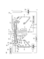
- FIG. 1 is an illustrative sectional view for explaining the configuration of a substrate processing apparatus according to a first embodiment of the present invention.
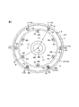
- FIG. 2 is a plan view for explaining a more specific configuration of the spin chuck provided in the substrate processing apparatus.
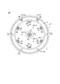
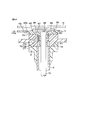
- FIG. 3 is a bottom view of the configuration of FIG. 4 is a cross-sectional view taken along section line IV-IV in FIG. 4A is an enlarged cross-sectional view showing a part of the configuration of FIG. 4 in an enlarged manner.
- FIG. 5 is an enlarged cross-sectional view showing a configuration in the vicinity of the movable pin provided in the spin chuck.
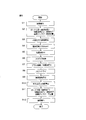
- FIG. 6 is a flowchart for explaining an operation example of the substrate processing apparatus.
- FIG. 6 is a flowchart for explaining an operation example of the substrate processing apparatus.
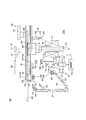
- FIG. 7 is an illustrative cross-sectional view for explaining the configuration of a substrate processing apparatus according to the second embodiment of the present invention.
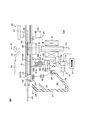
- FIG. 8 is an illustrative sectional view for explaining the configuration of a substrate processing apparatus according to a third embodiment of the present invention.
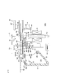
- FIG. 9 is an illustrative sectional view for explaining the configuration of a substrate processing apparatus according to a fourth embodiment of the present invention.
- FIG. 10 is an illustrative sectional view for explaining the configuration of a substrate processing apparatus according to the fifth embodiment of the present invention.
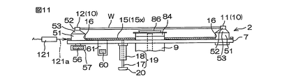
- FIG. 11 is a diagram illustrating a configuration example for detecting the position of the protection disk.
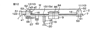
- FIG. 12 is a diagram showing another configuration example for detecting the position of the protection disk.
- FIG. 13 is a diagram showing still another configuration example for detecting the position of the protection disk.
- FIG. 14 is a diagram showing still another configuration example for detecting the position of the protection disk.
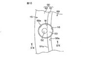
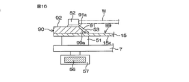
- FIG. 15 is an enlarged plan view showing another configuration example of the protective disk. 16 is a cross-sectional view taken along a cutting line viewed in the direction of arrow XVI shown in FIG.
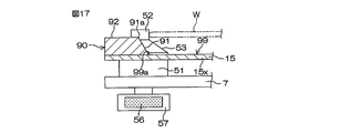
- FIG. 17 is an enlarged plan view showing another configuration example of the protective disk.
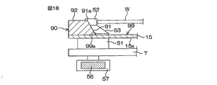
- FIG. 18 is an enlarged plan view showing another configuration example of the protective disk.
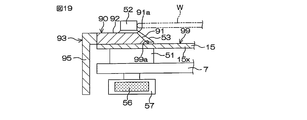
- FIG. 19 is an enlarged plan view showing another configuration example of the protective disk.
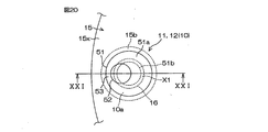
- FIG. 20 is an enlarged plan view showing another configuration example of the holding pin and the protective disk.
- FIG. 21 is a cross-sectional view taken along the cutting line viewed in the direction of arrows XXI-XXI shown in FIG.
- FIG. 1 is an illustrative sectional view for explaining the configuration of a substrate processing apparatus according to a first embodiment of the present invention.
- the substrate processing apparatus 1 is a single wafer type apparatus that processes substrates W such as semiconductor wafers one by one.
- the substrate processing apparatus 1 includes a spin chuck 2, a rotation drive mechanism 3, a splash guard 4, and a guard drive mechanism 5.
- the spin chuck 2 includes a turntable 7 that can rotate around a rotation axis 6 along the vertical direction.
- a rotating shaft 8 is coupled to a lower surface of the rotation center of the turntable 7 via a boss 9.
- the rotation shaft 8 extends along the vertical direction, and is configured to rotate around the rotation axis 6 upon receiving a driving force from the rotation driving mechanism 3.
- the rotation drive mechanism 3 may be an electric motor having the rotation shaft 8 as a drive shaft, for example.
- the spin chuck 2 further includes a plurality of (six in this embodiment) holding pins 10 provided at intervals along the circumferential direction on the peripheral edge of the upper surface of the turntable 7.
- the holding pins 10 are configured to hold the substrate W horizontally at an upper substrate holding height that is spaced a certain distance from the turntable 7 having a substantially horizontal upper surface.
- the spin chuck 2 further includes a protective disk 15 disposed between the upper surface of the turntable 7 and the substrate holding height by the holding pins 10.
- the protection disk 15 is coupled to the turntable 7 so as to be movable up and down, and is provided at a lower position near the upper surface of the turntable 7 and on a lower surface of the substrate W held by the holding pins 10 above the lower position. It is possible to move between close positions that are close to each other with a small gap.
- the protective disk 15 is a disk-shaped member having an outer diameter larger than the diameter of the substrate W. That is, in this embodiment, the protective disk 15 is constituted by the disk body 15x having an outer diameter larger than the diameter of the substrate W.
- An opening 16 is formed at a peripheral edge of the protective disk 15 at a position corresponding to the holding pin 10. That is, a plurality of openings 16 corresponding to the plurality of holding pins 10 are formed at the peripheral edge of the protection disk 15, and the plurality of holding pins 10 are inserted into the plurality of openings 16, respectively.
- the opening 16 surrounds the entire circumference of the holding pin 10 with an interval in the radial direction of the holding pin 10, and the holding pin 10 protrudes upward from the opening 16.
- the splash guard 4 is a cylindrical member that surrounds the periphery of the spin chuck 2 from the side, and is a receiving member that receives the processing liquid discharged outward from the substrate W held by the spin chuck 2. More specifically, the splash guard 4 includes a cylindrical portion 21 that is coaxial with the rotation axis 6, an upper guide portion 22 that protrudes obliquely upward from the inner wall surface of the cylindrical portion 21 toward the inward direction approaching the rotation axis 6, and a lower guide portion 22. And a guide portion 23.
- the upper guide portion 22 is formed in a shape along a partial conical surface, and an inner edge thereof is disposed outside the spin chuck 2 with a predetermined interval.
- the lower guide part 23 is provided below the upper guide part 22 at a certain interval, and also has a shape along the partial conical surface.
- the inner edge of the lower guide part 23 reaches inward from the outer peripheral edge of the spin chuck 2 in plan view.
- a processing liquid port 24 for receiving the processing liquid discharged from the substrate W held on the spin chuck 2 is defined between the upper guide part 22 and the lower guide part 23.
- a guard drive mechanism 5 is provided to move the splash guard 4 up and down along the rotation axis 6.
- the guard drive mechanism 5 may include a linear drive mechanism such as an air cylinder or a ball screw mechanism.
- the substrate processing apparatus 1 further includes a processing liquid supply unit 30 and a brush cleaning mechanism 35.
- the processing liquid supply unit 30 includes a processing liquid nozzle 31 that discharges the processing liquid toward the surface of the substrate W, and supplies the processing liquid from the processing liquid supply source 32 to the processing liquid nozzle 31 via the processing liquid supply pipe 33. Is configured to do.
- a processing liquid valve 34 is interposed in the middle of the processing liquid supply pipe 33. Therefore, by opening / closing the processing liquid valve 34, it is possible to switch the discharge / stop of the processing liquid from the processing liquid nozzle 31.
- the brush cleaning mechanism 35 contacts the upper surface of the substrate W to scrub and clean the substrate W, a swing arm 37 that holds the cleaning brush 36 at the tip, and a drive for the swing arm 37.
- the arm drive mechanism 38 is configured to be able to swing the swing arm 37 along a horizontal plane and to move the swing arm 37 up and down. With this configuration, when the substrate W is rotated while being held by the spin chuck 2, the cleaning brush 36 is pressed against the upper surface of the substrate W, and the pressing position is moved in the radial direction of the substrate W. The entire upper surface of the substrate can be scrubbed.
- a processing liquid for example, deionized water
- the foreign matter scraped off by the step can be discharged out of the substrate.
- the rotary shaft 8 is a hollow shaft, and an inert gas supply pipe 70 is inserted through the rotary shaft 8.
- An inert gas supply path 72 that guides an inert gas from an inert gas supply source 71 is coupled to the lower end of the inert gas supply pipe 70.
- An inert gas valve 73 is interposed in the middle of the inert gas supply path 72. The inert gas valve 73 opens and closes the inert gas supply path 72. By opening the inert gas valve 73, the inert gas is fed into the inert gas supply pipe 70. This inert gas is supplied to a space between the protective disk 15 and the lower surface of the substrate W by a configuration described later.
- the inert gas supply unit 74 includes the inert gas supply pipe 70, the inert gas supply source 71, the inert gas supply path 72, the inert gas valve 73, and the like.
- the substrate processing apparatus 1 includes a control device 40 for controlling each part thereof.
- the control device 40 is configured to control the rotation drive mechanism 3, the guard drive mechanism 5, the processing liquid valve 34, the arm drive mechanism 38, the inert gas valve 73, and the like.
- FIG. 2 is a plan view for explaining a more specific configuration of the spin chuck 2
- FIG. 3 is a bottom view thereof
- FIG. 4 is a cross-sectional view taken along the section line IV-IV in FIG. .
- the turntable 7 is formed in a disc shape along a horizontal plane, and is connected to a boss 9 connected to a rotating shaft 8.
- the plurality of holding pins 10 are arranged at equal intervals along the circumferential direction on the periphery of the upper surface of the turntable 7.
- the holding pin 10 includes a fixed pin 11 that does not move with respect to the turntable 7 and a movable pin 12 that moves with respect to the turntable 7.
- two holding pins 10 arranged adjacent to each other are movable pins 12.
- Each of the holding pins 10 includes a lower shaft portion 51 coupled to the turntable 7, and an upper shaft portion 52 formed integrally with the upper end of the lower shaft portion 51, and the lower shaft portion 51 and the upper shaft portion 52. Are each formed in a cylindrical shape.
- the upper shaft portion 52 is provided eccentric from the central axis of the lower shaft portion 51.
- the surface connecting the upper end of the lower shaft portion 51 and the lower end of the upper shaft portion 52 forms a tapered surface 53 that descends from the upper shaft portion 52 toward the peripheral surface of the lower shaft portion 51.
- the movable pin 12 is coupled to the turntable 7 so that the lower shaft portion 51 can rotate around the rotation axis 12a coaxial with the center axis. More specifically, a support shaft 55 is provided at the lower end portion of the lower shaft portion 51 so as to be supported with respect to the turntable 7 via a bearing 54. A magnet holding member 57 holding a pin driving permanent magnet 56 is coupled to the lower end of the support shaft 55. The pin driving permanent magnet 56 is disposed, for example, with the magnetic pole direction oriented in a direction orthogonal to the rotation axis 12 a of the movable pin 12.
- the protective disk 15 is a disk-shaped member having an outer diameter larger than the diameter of the substrate W.
- the outer peripheral surface of the protection disk 15 is disposed outward from the position where the holding pin 10 is disposed.
- the outer diameter of the protective disk 15 is equal to the outer diameter of the turntable 7, and the outer peripheral surface of the protective disk 15 and the outer peripheral face of the turntable 7 are arranged on a common cylindrical surface extending in the vertical direction. An example is shown.
- the outer diameter of the protective disk 15 may be smaller or larger than the outer diameter of the turntable 7.
- a circular opening corresponding to the boss 9 is formed in the central area of the protective disk 15.
- a guide shaft 17 extending in the vertical direction in parallel with the rotation axis 6 is coupled to the lower surface of the protective disk 15 at a position farther from the rotation axis 6 than the boss 9.
- the guide shafts 17 are arranged at three positions that are equally spaced in the circumferential direction of the protective disk 15. More specifically, three guide shafts 17 are arranged at angular positions corresponding to every other holding pin 10 when viewed from the rotation axis 6.
- the guide shaft 17 is coupled to a linear bearing 18 provided at a corresponding position of the turntable 7, and is movable in the vertical direction, that is, a direction parallel to the rotation axis 6 while being guided by the linear bearing 18. Therefore, the guide shaft 17 and the linear bearing 18 constitute a guide mechanism 19 that guides the protective disk 15 along the vertical direction parallel to the rotation axis 6.
- the guide shaft 17 passes through the linear bearing 18 and has a flange 20 protruding outward at the lower end thereof.
- the flange 20 contacts the lower end of the linear bearing 18, the upward movement of the guide shaft 17, that is, the upward movement of the protective disk 15 is restricted. That is, the flange 20 is a restricting member that restricts the upward movement of the protective disk 15.
- a magnet holding member 61 holding a protective disk side permanent magnet 60 is protected at an outer position farther from the rotation axis 6 than the guide shaft 17 and closer to the rotation axis 6 than the holding pin 10. It is fixed to the lower surface of the disk 15.
- the protective disk side permanent magnet 60 is held by the magnet holding member 61 with the magnetic pole direction directed in the vertical direction.
- the protective disk side permanent magnet 60 may be fixed to the magnet holding member 61 so as to have an S pole on the lower side and an N pole on the upper side.
- the magnet holding members 61 are provided at six locations at equal intervals in the circumferential direction.
- each magnet holding member 61 is arranged at an angular position corresponding to between the holding pins 10 adjacent to each other (in this embodiment, intermediate) as viewed from the rotation axis 6. Further, among the six angular regions divided (equally divided in this embodiment) by the six magnet holding members 61 as viewed from the rotational axis 6, within every other angular region (in this embodiment, in the angular region). Three guide shafts 17 are arranged at the center position).
- the through-hole 62 is formed in six places corresponding to the six magnet holding members 61 in the turntable 7. Each through hole 62 is formed so that the corresponding magnet holding member 61 can be inserted in a vertical direction parallel to the rotation axis 6.
- the magnet holding member 61 is inserted through the through hole 62 and protrudes downward from the lower surface of the turntable 7, and the protective disk side permanent magnet 60 is It is located below the lower surface of the turntable 7.
- the lower guide portion 23 of the splash guard 4 has a magnet holding portion 26 that holds a guard-side permanent magnet 25 at its upper end edge (inner edge).
- the guard-side permanent magnet 25 is formed in an annular shape coaxial with the rotation axis 6, and is disposed along a plane (horizontal plane) orthogonal to the rotation axis 6. More specifically, the guard-side permanent magnet 25 is disposed at a position farther than the protective disk-side permanent magnet 60 and closer to the pin driving permanent magnet 56 with respect to the rotation axis 6. That is, in plan view, the annular guard-side permanent magnet 25 is located between the protective disk-side permanent magnet 60 and the pin driving permanent magnet 56. The guard-side permanent magnet 25 is disposed at a position lower than the protective disk-side permanent magnet 60.
- the magnetic pole direction of the guard-side permanent magnet 25 is in the horizontal direction, that is, the rotational radius direction of the turntable 7.
- the guard side permanent magnet 25 is configured to have the same magnetic pole, that is, the south pole in a ring shape inward in the rotational radius direction.
- the processing liquid port 24 partitioned between the upper guide portion 22 and the lower guide portion 23. Is opposed to the substrate W in the horizontal direction.
- the guard-side permanent magnet 25 opposes the pin-shaped permanent magnet 56 in the horizontal direction with the ring-shaped magnetic pole arranged radially outward.
- the movable pin 12 is driven to the holding position by the magnetic force acting between the guard-side permanent magnet 25 and the pin driving permanent magnet 56, and is held at the holding position.
- the movable pin 12 has the upper shaft portion 52 at a position eccentric from the rotation axis 12a (see FIG. 5). Therefore, due to the rotation of the lower shaft portion 51, the upper shaft portion 52 is displaced between a distant open position away from the rotation axis 6 and a holding position approaching the rotation axis 6.
- the pin driving permanent magnet 56 is arranged so that the upper shaft portion 52 moves to the holding position approaching the rotation axis 6 when receiving the attractive magnetic force from the guard-side permanent magnet 25. Since the guard-side permanent magnet 25 is formed in an annular shape that is coaxial with the rotation axis 6, the guard-side permanent magnet 25 does not depend on the rotation position of the movable pin 12 around the rotation axis 6, that is, even if the turntable 7 is rotating. The attractive magnetic force between the side permanent magnet 25 and the pin driving permanent magnet 56 is maintained, whereby the movable pin 12 is held at the holding position where the substrate W is held.
- the splash guard 4 when the splash guard 4 is in the processing position (see FIG. 4), a repulsive magnetic force acts between the guard-side permanent magnet 25 and the protective disk-side permanent magnet 60, and the protective disk-side permanent magnet 60 applies an upward external force. receive.
- the protective disk 15 receives an upward force from the magnet holding member 61 holding the protective disk side permanent magnet 60 and is held at a processing position close to the lower surface of the substrate W.
- the repulsive magnetic force between the guard-side permanent magnet 25 and the protective disk-side permanent magnet 60 is small. It is held at a lower position near the upper surface of the turntable 7 by its own weight. Further, since the guard-side permanent magnet 25 does not face the pin driving permanent magnet 56, the external force that urges the movable pin 12 to the holding position does not act on the movable pin 12.
- the splash guard 4 is provided with a magnet holding portion 28 holding the release permanent magnet 27 further above the upper guide portion 22.
- the release permanent magnet 27 faces the pin driving permanent magnet 56.
- the release permanent magnet 27 is formed in an annular shape coaxial with the rotation axis 6, and has a ring-shaped magnetic pole inside the rotation radius of the turntable 7.
- the magnetic pole inside the rotation radius has the same polarity as the magnetic pole outside the rotation radius of the guard-side permanent magnet 25.
- the release permanent magnet 27 generates a magnetic force that rotationally displaces the movable pin 12 to the open position with respect to the pin driving permanent magnet 56. More specifically, if the guard-side permanent magnet 25 has a ring-shaped N pole on the outer side, the release permanent magnet 27 may be configured to have a ring-shaped N pole on the inner side. Good.
- the protective disk 15 is in the lower position close to the upper surface of the turntable 7, and the movable pin 12 is held in the open position.
- the substrate transport robot that carries the substrate W in and out of the spin chuck 2 can cause the substrate holding hand 45 to enter the space between the protective disk 15 and the lower surface of the substrate W.
- the magnetic levitation mechanism 41 is configured to be levitated and guided to the processing position.
- the pin driving permanent magnet 56, the guard-side permanent magnet 25, and the guard driving mechanism 5 constitute a magnetic driving mechanism 42 that holds the movable pin 12 in its holding position by the magnetic force between the permanent magnets 25 and 56. is doing.
- the magnetic levitation mechanism 41 and the magnetic drive mechanism 42 share the guard-side permanent magnet 25, the splash guard 4 as a support member that supports the guard-side permanent magnet 25, and the guard drive mechanism 5 that raises and lowers the splash guard 4. is doing.
- the protective disk 15 is held in the approach position by the magnetic repulsive force between the guard-side permanent magnet 25 and the protective disk-side permanent magnet 60, and the guard-side permanent magnet 25
- the movable pin 12 is held at the holding position by the magnetic attraction force with the pin driving permanent magnet 56.
- the boss 9 coupled to the upper end of the rotating shaft 8 holds a bearing mechanism 75 for supporting the upper end portion of the inert gas supply pipe 70.
- the bearing mechanism 75 includes a spacer 77 fitted and fixed in a recess 76 formed in the boss 9, a bearing 78 disposed between the spacer 77 and the inert gas supply pipe 70, and the spacer 77 and the spacer 77.
- a magnetic fluid bearing 79 provided above the bearing 78 between the active gas supply pipe 70 and the active gas supply pipe 70 is provided.
- the boss 9 integrally has a flange 81 protruding outward along a horizontal plane, and the turntable 7 is coupled to the flange 81. Further, the above-described spacer 77 is fixed to the flange 81 so as to sandwich the inner peripheral edge of the turntable 7, and a cover 84 is coupled to the spacer 77.
- the cover 84 is formed in a substantially disc shape, and has an opening for exposing the upper end of the inert gas supply pipe 70 in the center, and a recess 85 having the opening as a bottom surface is formed on the upper surface thereof. .
- the recess 85 has a horizontal bottom surface and an inverted conical inclined surface 83 that rises obliquely upward from the periphery of the bottom surface outward.
- a rectifying member 86 is coupled to the bottom surface of the recess 85.
- the rectifying member 86 has a plurality of (for example, four) leg portions 87 that are discretely arranged at intervals around the rotation axis 6 along the circumferential direction.
- a bottom surface 88 is disposed at a distance from the bottom surface.
- An inclined surface 89 formed of an inverted conical surface extending obliquely upward from the peripheral edge of the bottom surface 88 is formed.
- a flange 84a is formed on the outer periphery of the upper surface of the cover 84 so as to face outward.
- the flange 84a is aligned with a step portion 15a formed on the inner peripheral edge of the protective disk 15. That is, when the protective disk 15 is in an approach position close to the lower surface of the substrate W, the flange 84a and the stepped portion 15a are combined, and the upper surface of the cover 84 and the upper surface of the protective disk 15 are located in the same plane and are flat. An inert gas flow path is formed.
- the inert gas flowing out from the upper end of the inert gas supply pipe 70 exits into the space defined by the bottom surface 88 of the rectifying member 86 in the recess 85 of the cover 84.
- This inert gas is further blown out in the radial direction away from the rotation axis 6 through the radial flow path 82 defined by the inclined surface 83 of the recess 85 and the inclined surface 89 of the rectifying member 86. become.
- This inert gas forms an air flow of the inert gas in a space between the protective disk 15 and the lower surface of the substrate W held by the holding pins 10, and outwards in the rotational radius direction of the substrate W from the space. Blow out.
- FIG. 6 is a flowchart for explaining an operation example of the substrate processing apparatus 1.
- the substrate W to be processed is loaded into the substrate processing apparatus 1 by the substrate holding hand 45 of the substrate transfer robot and is transferred to the spin chuck 2 (step S1).
- the splash guard 4 is disposed at a retracted position (lower position) retracted downward from the side of the spin chuck 2.
- the release permanent magnet 27 faces the pin driving permanent magnet 56, and the movable pin 12 is held in the open position.
- the guard-side permanent magnet 25 held by the lower guide portion 23 of the splash guard 4 is far away from the rotary table 7, the repulsion acting between the guard-side permanent magnet 25 and the protective disk-side permanent magnet 60. Magnetic force is small. Therefore, the protective disk 15 is located at a lower position close to the upper surface of the turntable 7. Therefore, a sufficient space for the substrate holding hand 45 to enter is secured between the substrate holding height by the holding pins 10 and the upper surface of the protective disk 15.
- the substrate holding hand 45 conveys the substrate W to above the spin chuck 2 while holding the substrate W at a position higher than the upper end of the holding pin 10. Thereafter, the substrate holding hand 45 is lowered toward the upper surface of the turntable 7. In the process, the substrate W is transferred from the substrate holding hand 45 to the holding pins 10. The substrate holding hand 45 descends to the space between the lower surface of the substrate W and the protection disk 15, and then retracts to the side of the spin chuck 2 through the holding pins 10.
- the control device 40 controls the guard driving mechanism 5 to raise the splash guard 4 to the processing position (step S2).
- the processing liquid port 24 defined by the upper guide portion 22 and the lower guide portion 23 faces the side of the spin chuck 2, more specifically, the side of the substrate W.
- An annular guard-side permanent magnet 25 held on the inner edge of the lower guide portion 23 faces the pin driving permanent magnet 56.
- the movable pin 12 is driven from the open position to the holding position, and is held at the holding position. In this way, the substrate W is gripped by the fixed pin 11 and the movable pin 12.
- the guard-side permanent magnet 25 approaches the protective disk-side permanent magnet 60 from below, and the distance between the permanent magnets 25 and 60 is reduced.
- the repulsive magnetic force acting between them increases. Due to the repulsive magnetic force, the protective disk 15 floats from the upper surface of the turntable 7 toward the substrate W.
- the protective disk 15 reaches the approaching position approaching the lower surface of the substrate W with a minute gap, and the flange 20 formed at the lower end of the guide shaft 17 is the linear bearing 18. Abut. Thereby, the protection disk 15 is held at the approach position.
- the control device 40 opens the inert gas valve 73 and starts supplying inert gas (step S3).
- the supplied inert gas is discharged from the upper end of the inert gas supply pipe 70, and moves toward a narrow space between the protective disk 15 at the approach position and the lower surface of the substrate W by the function of the rectifying member 86 and the like. It blows off radially about the rotation axis 6.
- the inert gas is guided to the outside of the substrate W while being guided by a gas flow path formed by the upper surface of the protective disk 15 and the lower surface of the substrate W.
- the control device 40 further controls the rotation drive mechanism 3 to start the rotation of the turntable 7, thereby rotating the substrate W around the rotation axis 6 (step S4).
- the rotation speed may be about 100 rpm.
- the control device 40 opens the processing liquid valve 34.
- the processing liquid is supplied from the processing liquid nozzle 31 toward the upper surface of the substrate W (step S5).
- the supplied processing liquid receives a centrifugal force on the upper surface of the substrate W, spreads outward, and reaches the entire surface of the substrate W.
- the processing liquid discharged outward from the substrate W by centrifugal force is received by the splash guard 4 and discharged.
- control device 40 performs scrub cleaning of the upper surface of the substrate W by the brush cleaning mechanism 35 by controlling the arm drive mechanism 38 (step S6). Accordingly, scrub cleaning is performed on the upper surface of the substrate W by the cleaning brush 36 while supplying the processing liquid.
- the lower surface of the substrate W is covered with the protective disk 15. Moreover, an outward inert gas stream is formed in the space between the protective disk 15 and the lower surface of the substrate W, and this inert gas is blown out of the substrate W. Therefore, even if the mist of the processing liquid is dispersed around the spin chuck 2, it is possible to avoid or suppress the mist from adhering to the lower surface of the substrate W. Therefore, while avoiding the back surface of the substrate W from being subjected to a treatment such as back rinse, while maintaining the dry state, the adhesion of the processing liquid mist to the bottom surface of the substrate W is avoided or suppressed, and the substrate W A selective scrub cleaning process on the top surface can be performed.
- the control device 40 controls the arm drive mechanism 38 to retract the cleaning brush 36 from the upper side of the spin chuck 2 to the side thereof, closes the processing liquid valve 34, and sets the processing liquid nozzle.
- the discharge of the processing liquid from 31 is stopped (step S7).
- the control device 40 accelerates the rotation speed of the turntable 7 by controlling the rotation drive mechanism 3.
- a spin dry process is performed to dry the substrate W by shaking off the droplets on the upper surface and the peripheral end surface of the substrate W by centrifugal force (step S8).
- the rotation speed of the substrate W during this spin dry process is, for example, 1500 to 3000 rpm.
- the control device 40 controls the rotation drive mechanism 3 to stop the rotation of the substrate W (step S9). Further, the control device 40 closes the inert gas valve 73 and stops the supply of the inert gas (step S10). Then, the control device 40 controls the guard driving mechanism 5 to lower the splash guard 4 to the lower retracted position (step S11). In the process in which the splash guard 4 is lowered, the distance between the guard-side permanent magnet 25 and the protective disk-side permanent magnet 60 increases, and the magnetic repulsive force between them increases. Accordingly, the protective disk 15 is lowered toward the upper surface of the turntable 7 while being guided by the guide mechanism 19 due to its own weight.
- control device 40 controls the substrate transport robot to cause the substrate holding hand 45 to enter the space secured between the protective disk 15 and the lower surface of the substrate W. Then, the substrate holding hand 45 scoops the substrate W held by the holding pins 10 and then retracts to the side of the spin chuck 2. Thus, the processed substrate W is unloaded (step S12).
- the guard-side permanent magnet 25 held by the splash guard 4 is formed in an annular shape coaxial with the rotation axis 6, during the rotation of the turntable 7, It faces the pin driving permanent magnet 56 and continues to give a sufficient magnetic repulsive force to the protective disk side permanent magnet 60.
- the external force for urging the movable pin 12 to the holding position and the external force for holding the protective disk 15 at the approach position close to the lower surface of the substrate W are non-rotating. It can give in a non-contact state from the guard side permanent magnet 25 arrange
- the driving force is not obtained by using the rotation of the turntable 7, even when the substrate W is rotating at a low speed as in the scrub cleaning process, the rotation of the substrate W is stopped. Even when the movable pin 12 is in operation, the movable pin 12 can exhibit a sufficient substrate holding force, and the protective disk 15 is reliably kept in the approach position. Therefore, it is possible to perform the processing on the upper surface of the substrate W while reliably avoiding or suppressing the deposition of the processing liquid mist on the lower surface of the substrate W.
- the magnetic levitation mechanism 41 that levitates the protection disk 15 above the turntable 7 and the magnetic drive mechanism 42 that drives the movable pin 12 are guard side held by the splash guard 4.
- the permanent magnet 25 is used in common. Therefore, the guard drive mechanism 5 for raising and lowering the splash guard 4 can be shared as a drive source for the magnetic levitation mechanism 41 and the magnetic drive mechanism 42, thereby making the configuration remarkably simple. Furthermore, since the magnetic levitation mechanism 41 and the magnetic drive mechanism 42 are not configured to incorporate a drive unit in a rotating system that rotates together with the turntable 7, their configuration is simple, and thereby the configuration of the substrate processing apparatus 1. Can be further simplified.
- the magnetic levitation mechanism 41 and the magnetic drive mechanism 42 are configured to transmit the driving force from the non-rotating system to the rotating system in a non-contact manner using magnetic force. No frictional contact occurs. Thereby, generation of particles can be reduced, and substrate processing with high cleanliness can be realized.
- the inert gas is supplied to the space between the protective disk 15 and the lower surface of the substrate W at the approach position, the treatment liquid mist adheres more effectively to the lower surface of the substrate W. Can be avoided or suppressed. Since the inert gas is blown out radially from the rotation axis 6 toward the outer peripheral edge of the substrate W by the function of the rectifying member 86 and the like, the inert gas is stabilized between the lower surface of the substrate W and the protective disk 15. An outward airflow can be formed. This also makes it possible to more effectively avoid or suppress the adhesion of the processing liquid mist to the lower surface of the substrate W.
- the protective disk 15 since the outer diameter of the protective disk 15 is larger than the diameter of the substrate W, the lower surface of the substrate W can be effectively protected from below. That is, the protective disk 15 can protect a wider range of the substrate W than when the outer diameter of the protective disk 15 is smaller than or equal to the diameter of the substrate W. Further, since the protective disk 15 is larger than the substrate W, the airflow flowing outward between the protective disk 15 and the turntable 7 is reliably guided outward from the substrate W by the protective disk 15. Therefore, even if an airflow flowing upward from between the outer periphery of the protective disk 15 and the outer periphery of the turntable 7 is generated, this airflow is unlikely to contact the peripheral edge of the substrate W. Therefore, it is possible to suppress or prevent the substrate W from being contaminated by particles contained in the airflow.
- the outer peripheral surface of the protective disk 15 is arranged outward from the holding pin 10.
- the holding pin 10 When the holding pin 10 rotates together with the substrate W by the rotation of the turntable 7, the holding pin 10 causes turbulence of the airflow.
- the holding pin 10 When the holding pin 10 is disposed outward from the outer peripheral surface of the protective disk 15, the turbulence of the air flow affects the atmosphere around the substrate W, which may cause adhesion of foreign matters such as particles.
- the holding pin 10 when the holding pin 10 is disposed inward from the outer peripheral surface of the protective disk 15, the turbulence of the airflow by the holding pin 10 is suppressed by the protective disk 15, and as a result, contamination to the substrate W is prevented. Can be suppressed or prevented.
- FIG. 7 is a schematic cross-sectional view for explaining the configuration of the substrate processing apparatus 102 according to the second embodiment of the present invention.
- the guard drive mechanism 5 for raising and lowering the splash guard 4 is also used as a drive source for the magnetic levitation mechanism 41 and the magnetic drive mechanism 42.
- a dedicated drive source for the magnetic levitation mechanism 41 is provided.
- the magnetic levitation mechanism 41 includes a protective disk side permanent magnet 60, a disk lifting / lowering permanent magnet 64, and a lifting / lowering actuator 65.
- the disk lifting / lowering permanent magnet 64 is an annular permanent magnet piece disposed along a horizontal plane with the rotation axis 6 as the center, and has an annular magnetic pole facing the protective disk side permanent magnet 60 from below. ing.
- the polarity of the magnetic pole is the same as that of the lower magnetic pole of the protective disk side permanent magnet 60. Therefore, the disk lifting / lowering permanent magnet 64 causes an upward repulsive magnetic force to act on the protective disk side permanent magnet 60.
- the disk lifting / lowering permanent magnet 64 is housed and held in an annular magnet holding member 66.
- An operating shaft 65 a of the lifting actuator 65 is coupled to the magnet holding member 66.
- the elevating actuator 65 is composed of, for example, an air cylinder, and is configured to move the operating shaft 65a up and down in a direction parallel to the rotation axis 6.
- the operation of the lift actuator 65 is controlled by the control device 40.
- the raising / lowering actuator 65 can arrange
- the upper position is a position above the lower position, and the protective disk 15 coupled to the magnet holding member 61 is moved to the substrate W by the magnetic repulsion between the disk elevating permanent magnet 64 and the protective disk side permanent magnet 60. It is set to a position where it can be raised to an approach position (processing height) that is close to the lower surface.
- the lifting / lowering actuator 65 when the lifting / lowering actuator 65 is operated to raise the disk lifting / lowering permanent magnet 64 from the lower position to the upper position, the magnetic repulsive force between the disk lifting / lowering permanent magnet 64 and the protection disk-side permanent magnet 60 in the process. Exceeds the gravity and other rising resistance forces (frictional force, etc.) acting on the protective disk 15. Thereby, the protection disk 15 floats from the upper surface of the turntable 7 and rises to an approach position (processing height) approaching the lower surface of the substrate W. The rising of the protection disk 15 is restricted by the flange 20 provided at the lower end of the guide shaft 17 coming into contact with the lower end of the linear bearing 18.
- the lifting / lowering actuator 65 when the lifting / lowering actuator 65 is operated to lower the disk lifting / lowering permanent magnet 64 from the upper position to the lower position, the gravity acting on the protection disk 15 in the process causes the disk lifting / lowering permanent magnet 64 and the protection disk side permanent. It exceeds the magnetic repulsive force between the magnet 60 and other descending resistance forces (frictional force, etc.). Thereby, the protection disk 15 descends from the approach position and reaches the turntable 7.
- the magnetic levitation mechanism 41 has a dedicated disk lifting / lowering permanent magnet 64 and a dedicated lifting / lowering actuator 65 that moves the disk up and down.
- the up-and-down movement of the protection disk 15 can be made independent of the up-and-down movement of the splash guard 4 and the driving of the movable pin 12. Therefore, for example, when a plurality of processing liquid ports stacked in the vertical direction are provided on the splash guard 4, and the processing liquid ports are switched according to the type of the processing liquid, the protective disk is used regardless of the switching of the processing liquid ports. 15 can be held in the approach position.
- FIG. 8 is a schematic cross-sectional view for explaining the configuration of a substrate processing apparatus 103 according to the third embodiment of the present invention.
- the same reference numerals are assigned to the corresponding parts in FIG.
- a dedicated drive source for the magnetic levitation mechanism 41 is provided as in the second embodiment.
- the magnetic levitation mechanism 41 includes a protective disk side permanent magnet 60, a disk lifting / lowering permanent magnet 64, and a lifting / lowering actuator 111.
- the disk lifting / lowering permanent magnet 64 is an annular permanent magnet piece disposed along a horizontal plane with the rotation axis 6 as the center, and has an annular magnetic pole facing the protective disk side permanent magnet 60 from below. ing.
- the polarity of the magnetic pole is the same as that of the lower magnetic pole of the protective disk side permanent magnet 60. Therefore, the disk lifting / lowering permanent magnet 64 causes an upward repulsive magnetic force to act on the protective disk side permanent magnet 60.
- the disk lifting / lowering permanent magnet 64 is housed and held in an annular magnet holding member 66.
- the magnet holding member 66 is coupled to the actuating member 111a of the elevating actuator 111.
- the elevating actuator 111 includes a ball screw mechanism 112 and an electric motor 113, and is configured to move the operating member 111a up and down in a direction parallel to the rotation axis 6.
- the ball screw mechanism 112 includes a screw shaft 114 disposed along a vertical direction parallel to the rotation axis 6 and a ball nut 115 screwed to the screw shaft 114, and an operation member 111a is coupled to the ball nut 115. Yes.
- the upper end of the screw shaft 114 is supported by the bearing 116, and the lower end of the screw shaft 114 is coupled to the drive shaft 113 a of the electric motor 113 via the coupling 117.
- the electric motor 113 is provided with a rotational position detection unit 118 that detects the rotational position of the drive shaft 113a.
- the rotational position detection unit 118 includes, for example, a rotary encoder, and an output signal thereof is input to the control device 40.
- the operation of the elevating actuator 111 is controlled by the control device 40.
- the lifting / lowering actuator 111 can arrange the disk lifting / lowering permanent magnet 64 at an arbitrary height between the upper position and the lower position. In the lower position, the disk lifting / lowering permanent magnet 64 is located sufficiently below the turntable 7, and the magnetic repulsive force between the disk lifting / lowering permanent magnet 64 and the protection disk side permanent magnet 60 is protected by the protection disk. 15 is set so that a sufficient distance can be secured so that the gravity acting on 15 is smaller.
- the upper position is a position above the lower position, and the protective disk 15 coupled to the magnet holding member 61 is moved to the substrate W by the magnetic repulsion between the disk elevating permanent magnet 64 and the protective disk side permanent magnet 60. It is set to a position where it can be raised to an approach position (processing height) that is close to the lower surface.
- the lifting / lowering actuator 111 when the lifting / lowering actuator 111 is operated to raise the disk lifting / lowering permanent magnet 64 from the lower position to the upper position, the magnetic repulsive force between the disk lifting / lowering permanent magnet 64 and the protective disk side permanent magnet 60 in the process. Exceeds the gravity and other rising resistance forces (frictional force, etc.) acting on the protective disk 15. Thereby, the protection disk 15 floats from the upper surface of the turntable 7 and rises to an approach position (processing height) approaching the lower surface of the substrate W. The rising of the protection disk 15 is restricted by the flange 20 provided at the lower end of the guide shaft 17 coming into contact with the lower end of the linear bearing 18.
- the lifting / lowering actuator 111 when the lifting / lowering actuator 111 is operated to lower the disk lifting / lowering permanent magnet 64 from the upper position to the lower position, the gravity acting on the protection disk 15 in the process causes the disk lifting / lowering permanent magnet 64 and the protection disk side permanent. It exceeds the magnetic repulsive force between the magnet 60 and other descending resistance forces (frictional force, etc.). Thereby, the protection disk 15 descends from the approach position and reaches the turntable 7.
- the position of the disk lifting / lowering permanent magnet 64 can be controlled to an arbitrary intermediate position between the upper position and the lower position as described above. . More specifically, the control device 40 detects the rotational position of the drive shaft 113a of the electric motor 113 by referring to the output signal of the rotational position detection unit 118, and based on the rotational position, the disk lifting / lowering permanent magnet is detected. The height of 64 is detected indirectly. Thus, the control device 40 can control the height of the disk lifting / lowering permanent magnet 64 to an arbitrary height between the upper position and the lower position. Thereby, the position of the protection disk 15 can be controlled not only at the two upper and lower positions but also at an arbitrary height position between the turntable 7 and the substrate holding height on the spin chuck 2.
- the control device 40 may be programmed to change the height of the protection disk 15 according to the processing content for the substrate W. For example, when scrub cleaning the upper surface of the substrate W with the cleaning brush 36, the substrate W bends downward. Therefore, the control device 40 may float the protective disk 15 from the turntable 7 and arrange it at a scrub cleaning height set so as not to contact the protective disk 15 even when the substrate W is bent downward. That is, the control device 40 may control the elevating actuator 111 so that the protective disk 15 has such a height.
- the substrate W is greatly bent downward.
- control device may control the elevating actuator 111 so that the protective disk 15 is disposed above the scrub cleaning height and the distance between the protective disk 15 and the lower surface of the substrate W is reduced. Thereby, it is possible to more reliably prevent the processing liquid mist from entering the lower surface of the substrate W.
- the magnetic levitation mechanism 41 has the dedicated disk lifting / lowering permanent magnet 64 and the dedicated lifting / lowering actuator 111 that moves the disk vertically.
- the up-and-down movement of the protection disk 15 can be made independent of the up-and-down movement of the splash guard 4 and the driving of the movable pin 12.
- the lift actuator 111 is configured to be able to control the protective disk 15 to an arbitrary height between the turntable 7 and the substrate holding height. The space between the lower surface of W can be adjusted appropriately.
- FIG. 9 is a schematic cross-sectional view for explaining the configuration of a substrate processing apparatus 104 according to the fourth embodiment of the present invention.
- the same reference numerals are assigned to the corresponding parts in FIG.
- the second disk lifting / lowering permanent magnet that faces the protective disk side permanent magnet 60 from above.
- a magnet 67 is provided. That is, the protective disk side permanent magnet 60 is sandwiched from above and below by the first and second disk lifting / lowering permanent magnets 64 and 67.
- the second disk lifting / lowering permanent magnet 67 is an annular permanent magnet piece arranged along a horizontal plane with the rotation axis 6 as the center, and an annular magnetic pole facing the protective disk side permanent magnet 60 from above. have.
- the polarity of the magnetic pole is the same as that of the upper magnetic pole of the protective disk side permanent magnet 60.
- the second disk lifting / lowering permanent magnet 67 causes a downward repulsive magnetic force to act on the protective disk side permanent magnet 60. Therefore, the protective disk side permanent magnet 60 receives an upward repulsive magnetic force from the first disk lifting / lowering permanent magnet 64 from below and a downward repulsive magnetic force from the second disk lifting / lowering permanent magnet 67 from above.
- the protective disk side permanent magnet 60 is non-contacted between the first and second disk lifting / lowering permanent magnets 64 and 67 at a position where the repulsive magnetic force and the gravity acting on the protective disk 15 and the like are balanced. Retained.
- annular magnet holding member 68 1st and 2nd disk raising / lowering permanent magnets 64 and 67 are incorporated and held in an annular magnet holding member 68.
- the magnet holding member 68 is coupled to the actuating member 111a of the elevating actuator 111.
- the magnet holding member 68 is configured such that a cross section perpendicular to the circumferential direction has a lateral U shape (in this embodiment, an outward U shape), and holds the first disk lifting permanent magnet 64.
- An annular lower holding portion 68a, an annular upper holding portion 68b that holds the second disk lifting / lowering permanent magnet 67, and a cylindrical connecting cylinder portion 68c that connects the inner edges thereof are included.
- a space for accommodating the protective disk side permanent magnet 60 is formed outside the connecting cylinder part 68c.
- the tip 61a of the magnet holding member 61 is inserted into this space from the outer side in the rotational radial direction.
- the magnet holding member 61 has a hanging portion 61b that hangs down from the protective disk 15 and a tip portion 61a that extends inward from the lower end so as to approach the rotation axis 6 and is substantially L-shaped. Is formed.
- a protective disk side permanent magnet 60 is embedded in the tip portion 61a.
- the protective disk-side permanent magnet 60 can be used when the spin chuck 2 is in any rotational position.
- the magnetic force from the first and second disk elevating / lowering permanent magnets 64 and 67 is received and held between them in a non-contact state.
- the protective disk side permanent magnet 60 receives a magnetic repulsive force from above and below, its vertical position can be accurately controlled. Thereby, the position control accuracy of the protection disk 15 can be increased, and adhesion of the processing liquid mist or the like to the lower surface of the substrate W can be further suppressed.
- FIG. 10 is an illustrative sectional view for explaining the configuration of a substrate processing apparatus 105 according to the fifth embodiment of the present invention.
- the same reference numerals are assigned to the corresponding parts in FIG.
- a dedicated drive source for the magnetic levitation mechanism 41 is provided.
- the magnetic levitation mechanism 41 includes a protective disk side permanent magnet 60, a disk lifting / lowering electromagnet apparatus 97, and a height control electromagnet apparatus 98.
- the disk lifting / lowering electromagnet device 97 has an annular magnetic pole 97a disposed along a horizontal plane with the rotation axis 6 as the center, and the annular magnetic pole 97a faces the protective disk side permanent magnet 60 from below. is doing.
- the disk lifting / lowering electromagnet device 97 is energized by applying a current in the first direction, a magnetic pole having the same polarity as the lower magnetic pole of the protective disk side permanent magnet 60 appears in the magnetic pole 97a.
- the magnetic pole 97a has a magnetic pole having a polarity different from that of the lower magnetic pole of the protective disk side permanent magnet 60.
- the disk lifting / lowering electromagnet device 97 causes an upward repulsive magnetic force to act on the protective disk side permanent magnet 60 when a current in the first direction is applied. Further, the disk lifting / lowering electromagnet device 97 applies a downward attractive magnetic force to the protective disk side permanent magnet 60 when a current in the second direction is applied. If the energization is stopped, those magnetic forces disappear.
- the protective disk 15 is controlled to a lower position close to the turntable 7.
- the control device 40 Energization of the disk lifting / lowering electromagnet device 97 is controlled by the control device 40.
- the height control electromagnet device 98 includes a plurality of electromagnet units U1, U2, U3,... Each having an annular magnetic pole m1, m2, m3,. ing.
- the magnetic poles m1, m2, m3,... Are vertically aligned parallel to the rotation axis 6 at equal intervals with the cylindrical magnetic pole surfaces having the same radius facing each other outward (the direction opposite to the rotation axis 6).
- the magnetic poles m1, m2, m3,... are arranged inside the pass area of the protective disk side permanent magnet 60, but the magnetic poles m1, m2, m3,. It doesn't matter. Further, the magnetic poles m1, m2, m3,... Can be distributed and arranged inside and outside the pass area of the protective disk side permanent magnet 60.
- the height position of the protective disk side permanent magnet 60 can be controlled by controlling the energization direction and current magnitude of the electromagnet units U1, U2, U3,. That is, the control device 40 can control the height of the protective disk side permanent magnet 60, that is, the height of the protective disk 15 by controlling energization to the electromagnet units U 1, U 2, U 3,.
- the control device 40 When the control device 40 floats the protection disk 15 from the turntable 7 and controls the height thereof, the control device 40 supplies a current in the first direction to the disk lifting / lowering electromagnet device 97 and the electromagnet according to the control target height. Controls energization to the units U1, U2, U3,. Thereby, the protection disk 15 can be arrange
- size of the electric current supplied to the electromagnet apparatus 97 for raising / lowering a disk is controlled, the magnitude
- the height of the protective disk side permanent magnet 60 that is, the height of the protective disk 15 can be controlled. Therefore, the height control electromagnet device 98 may be omitted, and the height of the protective disk 15 may be controlled by energization control to the disk lifting / lowering electromagnet device 97.
- FIG. 11 is a diagram showing a configuration example for detecting the position of the protection disk 15.
- a photo sensor 121 is provided for detecting whether or not the protective disk 15 is at a lower position on the turntable 7.
- An output signal of the photosensor 121 is input to the control device 40.
- the photosensor 121 is disposed on the side of the turntable 7, and its detection optical axis 121 a is adjusted along a horizontal plane that aligns with the lower position of the protection disk 15.
- the detection optical axis 121a of the photosensor 121 and the protective disk 15 overlap. Therefore, it is possible to detect that the protection disk 15 is in the lower position by detecting light blocking or light reflection by the protection disk 15.
- the control apparatus 40 can confirm whether the protection disk 15 exists in a lower position, and can perform operation
- FIG. 12 is a diagram showing another configuration example for detecting the position of the protection disk 15.
- a line sensor 122 for detecting the height of the protective disk 15 on the turntable 7 is provided.
- the output signal of the line sensor 122 is input to the control device 40.
- the line sensor 122 is a multi-optical axis type line sensor having a plurality of optical axes a1, a2, a3,... So that the plurality of optical axes a1, a2, a3,. Is set.
- the plurality of optical axes a1, a2, a3,. Are arranged to match. Therefore, according to the height of the protective disk 15, any one of the optical axes a1, a2, a3,.
- the height of the protection disk 15 can be detected by detecting the light passing through each optical axis by the protection disk 15 or detecting the reflection of the light passing through the optical axis by the protection disk 15.
- the control device 40 obtains information on the height of the protection disk 15 and can confirm or control the operation of the magnetic levitation mechanism 41.
- FIG. 13 is a diagram showing still another configuration example for detecting the position of the protection disk 15.
- a camera 123 for detecting the height of the protective disk 15 on the turntable 7 is provided.
- the video signal output from the camera 123 is input to the control device 40.
- the camera 123 is arranged so as to photograph a region between the turntable 7 and the substrate holding height from the side of the spin chuck 2. Therefore, the protection area 15 is included in the photographing area.
- the control device 40 calculates the height of the protection disk 15 by processing the video signal output from the camera 123. As a result, the control device 40 obtains information on the height of the protection disk 15 and can confirm or control the operation of the magnetic levitation mechanism 41.
- FIG. 14 is a diagram showing still another configuration example for detecting the position of the protection disk 15.
- a distance sensor 124 for detecting the height of the protective disk 15 on the turntable 7 is provided.
- the output signal of the distance sensor 124 is input to the control device 40.
- the distance sensor 124 is disposed below the magnet holding member 61 as an interlocking member that moves together with the protection disk 15, and is configured to detect the distance to the magnet holding member 61.
- the distance sensor 124 may detect the distance from the distance sensor 124 to the guide shaft 17 or the flange 20. Since the magnet holding member 61 is coupled to the protection disk 15, the distance detected by the distance sensor 124 corresponds to the height of the protection disk 15 on the turntable 7.
- the distance sensor 124 may be configured to generate a search signal such as a search ultrasonic wave or a search light and measure the distance by detecting the search signal reflected by the magnet holding member 61.
- the control device 40 can obtain information on the height of the protective disk 15 based on the output signal of the distance sensor 124, and can confirm or control the operation of the magnetic levitation mechanism 41 based on the information.
- the throttle unit 90 may be provided at the peripheral edge of the protective disk 15. That is, the protective disk 15 may be configured by a disk main body 15x that is larger than the substrate W, and a throttle section 90 disposed above the outer periphery of the disk main body 15x.
- FIG. 15 is an enlarged plan view showing another configuration example of the protective disk 15.
- 16 is a cross-sectional view taken along a cutting line viewed in the direction of arrow XVI shown in FIG. FIG. 16 illustrates the case where the protective disk 15 is located at the approach position (upper position).
- the upper surface of the protection disk 15 shown in FIG. 15 and FIG. 16 includes an opposing portion 99 disposed below the substrate W, an inward portion 91 extending upward from the outer periphery of the opposing portion 99, and an outer end from the upper end of the inward portion 91. And an outer peripheral portion 92 extending in the direction.
- a projecting throttle portion 90 is formed by the inward portion 91 and the outer peripheral portion 92 of the protective disk 15.
- the restricting portion 90 restricts the flow path of the inert gas at the edge portion of the substrate W held by the holding pins 10.
- the throttle portion 90 is disposed on the peripheral edge of the protective disk 15 and is formed in an annular shape in plan view.
- the recess 90a is disposed at a position that aligns with the opening 16 in which the holding pin 10 is inserted.
- the inner surface of the recess 90a that defines the space inside the recess 90a is disposed above the inner peripheral surface of the opening 16 that defines the space inside the opening 16, and overlaps the inner peripheral surface of the opening 16 in plan view. Yes.
- the inner surface of the recess 90 a surrounds the holding pin 10 with a space in the radial direction of the holding pin 10.
- the facing portion 99 which is a part of the upper surface of the protection disk 15 faces the lower surface of the substrate W.
- the facing portion 99 includes an outer periphery 99 a disposed inward from the peripheral end surface of the substrate W.
- the diameter of the outer periphery 99a is smaller than the diameter of the substrate W. Therefore, the facing portion 99 has an outer diameter smaller than the diameter of the substrate W.
- the inward portion 91 of the protection disk 15 is disposed below the substrate W, and is formed in an annular shape in plan view so as to surround the outer periphery 99a of the facing portion 99.
- the inward portion 91 extends obliquely upward and outward from the outer periphery 99 a of the facing portion 99 of the protective disk 15.
- the inward portion 91 has an upper end 91 a disposed at a height between the protective disk 15 and the lower surface of the substrate W. As shown in FIG. 16, the upper end 91 a of the inward portion 91 is disposed outward from the peripheral end surface of the substrate W and is close to the peripheral end surface of the substrate W.
- the upper end 91a of the inward portion 91 may be disposed inward from the peripheral end surface of the substrate W, or is disposed at the same position (equal radius) as the peripheral end surface of the substrate W in the radial direction of the substrate W. Also good.
- the outer peripheral portion 92 of the protective disk 15 extends outward from the upper end 91 a of the inward portion 91, that is, the entire outer periphery of the inward portion 91. That is, the outer peripheral portion 92 is formed in an annular shape in plan view so as to surround the outer periphery of the inward portion 91.
- the upper surface of the outer peripheral portion 92 is located at a height between the protective disk 15 and the lower surface of the substrate W, similarly to the upper end 91 a of the inward portion 91.
- the outer peripheral portion 92 extends horizontally from the upper end 91 a of the inward portion 91 to the outer peripheral surface of the protective disk 15.
- the protective disk 15 has the throttle portion 90 on the upper surface for narrowing the flow path of the inert gas at the peripheral edge portion of the substrate W held by the holding pins 10.
- the throttle portion 90 has a protruding shape (in the example of FIG. 16, a trapezoidal cross section) defined by the inward portion 91 and the outer peripheral portion 92 of the protective disk 15.
- FIG. 17 is an enlarged cross-sectional view showing another configuration example of the protective disk 15.
- FIG. 17 illustrates the case where the protective disk 15 is located at the approach position (upper position).
- the configuration shown in FIG. 17 differs from the configuration shown in FIG. 16 in that the upper surface of the outer peripheral portion 92 of the protective disk 15 is substantially equal to the lower surface of the substrate W when the protective disk 15 is located at the approach position. And the upper end 91a of the inward portion 91 is located outside the substrate W.
- Other configurations are the same as the configurations of FIGS. 15 and 16 described above.
- FIG. 17 shows a configuration in which the inward portion 91 of the protection disk 15 is disposed outside the substrate W. However, the inward portion 91 is disposed so that a part of the inward portion 91 enters below the substrate W. It may be a configuration.
- the opposing portion 99 of the protective disk 15 has a configuration having an outer diameter substantially equal to the diameter of the substrate W, but is larger or smaller than the diameter of the substrate W depending on the arrangement of the inward portion 91. It may have an outer diameter.
- FIG. 18 is an enlarged cross-sectional view showing another configuration example of the protective disk 15.
- FIG. 18 illustrates the case where the protective disk 15 is located at the approach position (upper position).
- the configuration shown in FIG. 18 is different from the configuration shown in FIG. 16 in that the upper surface of the outer peripheral portion 92 of the protective disk 15 is at the same height as the upper surface of the substrate W when the protective disk 15 is located at the approach position. This is a point where the upper end 91a of the inward portion 91 is located outside the substrate W.
- Other configurations are the same as the configurations of FIGS. 15 and 16 described above. Even with such a configuration, the same effects as those described with reference to FIGS. 15, 16, and 17 can be exhibited.
- FIG. 19 is an enlarged cross-sectional view showing another configuration example of the protective disk 15.
- FIG. 19 illustrates the case where the protective disk 15 is located at the approach position (upper position).
- the 19 includes a disk main body 15x larger than the substrate W and a skirt portion 93 that moves up and down together with the disk main body 15x.
- the skirt portion 93 is fixed to the peripheral edge portion of the disc main body 15x.
- the skirt portion 93 is a side cover portion that covers the space between the lower surface of the substrate W and the turntable 7 from the side.
- the skirt portion 93 has a cut surface that is orthogonal to the circumferential direction and is formed in an L-shape that is substantially transverse. More specifically, the skirt portion 93 includes a throttle portion 90 and a hanging portion 95 that hangs vertically from the throttle portion 90 to the outside of the rotary table 7.
- the skirt portion 93 covers the space between the lower surface of the protective disk 15 (the lower surface of the disk main body 15x) and the turntable 7 from the side, and surrounds this space. Suppresses the involvement of the atmosphere. As a result, the airflow around the spin chuck 2 is stabilized, so that even higher quality substrate processing can be performed.
- the skirt portion 93 is retracted downward together with the protective disk 15 (disk main body 15x), and the substrate is held by the upper surface of the protective disk 15 (the upper surface of the disk main body 15x) and the holding pins 10. The space between them is open to the side. Therefore, the substrate holding hand 45 can enter the space and the substrate W can be carried in / out.
- connection portion between the facing portion 99 and the inward portion 91 has a polygonal cross section
- connection portion between the inward portion 91 and the outer peripheral portion 92 has a cross section.
- the connecting portion between the facing portion 99 and the inward portion 91 may have a curved cross section, and the facing portion 99 and the inward portion 91 may be smoothly connected.
- the connecting portion between the inward portion 91 and the outer peripheral portion 92 may have a curved cross section, and the inward portion 91 and the outer peripheral portion 92 may be smoothly connected.
- the outer peripheral portion 92 of the protective disk 15 extends horizontally from the upper end 91a of the inward portion 91 to the outer peripheral surface of the protective disk 15 has been described. It may be tilted. Specifically, the outer peripheral portion 92 may have a tapered shape extending outwardly diagonally upward or downward. Further, the outer peripheral portion 92 may be omitted, and the inward portion 91 may extend from the facing portion 99 to the outer peripheral surface of the protective disk 15.
- the guard drive mechanism 5 for raising and lowering the splash guard 4 is also used as a drive source for the magnetic drive mechanism 42.
- a drive source for the magnetic drive mechanism 42 is provided separately. Also good.
- the magnetic drive mechanism 42 that drives the movable pin 12 by magnetic force is provided.
- a drive mechanism for driving the movable pin 12 may be incorporated in the turntable 7.
- the inert gas is supplied to the space between the protective disk 15 and the lower surface of the substrate W. However, such supply of the inert gas may be omitted.
- the supply of the inert gas is stopped after the rotation of the substrate is stopped.
- the supply of the inert gas may be stopped when the spin dry process is started.
- the present invention can also be applied to a configuration in which the upper surface of W is cleaned.
- ultrasonic cleaning that supplies processing liquid with ultrasonic waves to the surface of the substrate
- high-pressure jet cleaning that supplies a high-speed flow of pressurized processing liquid to the surface of the substrate to clean the substrate.
- the present invention can also be applied to substrate processing.
- the present invention can be applied to a coating process in which a resist is applied to the surface of the substrate and a developing process in which a developer is supplied to the resist film after exposure.
- the configuration in which the movable pin 12 is driven using the attractive force between the permanent magnets has been described.
- the rotation axis 12 a of the movable pin 12 instead of the pin driving permanent magnet 56, the rotation axis 12 a of the movable pin 12.
- a permanent magnet is disposed at a position eccentric to the rotation axis 12 a of the movable pin 12, and an unmagnetized magnetic body is disposed at a position corresponding to the guard-side permanent magnet 25 and the release permanent magnet 27. The same operation can be realized.
- the magnetic pole direction of the guard-side permanent magnet 25 is the horizontal direction.
- the magnetic pole direction of the guard-side permanent magnet 25 may be the vertical direction. It may be slanted.
- the splash guard 4 moves up and down along the rotation axis 6 while the turntable 7 of the spin chuck 2 is arranged at a certain height.
- the same operation can be performed by fixing the splash guard 4 and moving the spin chuck 2 up and down.
- the same operation can be performed by moving both the spin chuck 2 and the splash guard 4 up and down.
- FIG. 20 is an enlarged plan view showing another configuration example of the holding pin 10 and the protection disk 15.
- FIG. 21 is a cross-sectional view taken along the cutting line viewed in the direction of arrows XXI-XXI shown in FIG.
- the holding pin 10 (each of the fixed pin 11 and the movable pin 12) includes a cylindrical lower shaft portion 51 disposed above the turntable 7 and an upper end of the lower shaft portion 51.
- the upper shaft portion 52 is provided so as to be eccentric from the center axis of the lower shaft portion 51.
- the surface connecting the upper end of the lower shaft portion 51 and the lower end of the upper shaft portion 52 forms a tapered surface 53 that descends from the upper shaft portion 52 toward the outer peripheral surface of the lower shaft portion 51.
- the holding pin 10 further includes a cylindrical recess 10a that is recessed from the outer peripheral surface of the holding pin 10 toward the central axis of the holding pin 10.
- the recess 10 a is provided on the outer peripheral portion of the lower shaft portion 51. Therefore, the holding pin 10 has a cylindrical or disc-like large diameter portion 51a having an outer diameter larger than the upper shaft portion 52 as a contact portion that contacts the peripheral end surface of the substrate W, and an outer diameter larger than the large diameter portion 51a.
- Including a small diameter portion 51b The small diameter portion 51b extends downward from the large diameter portion 51a and is coaxial with the large diameter portion 51a. Therefore, the upper shaft part 52 is eccentric with respect to the large diameter part 51a and the small diameter part 51b.
- the outer peripheral surface of the small-diameter portion 51 b of the holding pin 10 is located at the peripheral portion of the protective disk 15 (peripheral portion of the disc body 15 x) at a position corresponding to the small-diameter portion 51 b of the holding pin 10.
- An opening 16 surrounding the small-diameter portion 51b is formed with a certain distance therebetween. Specifically, the entire circumference of the small diameter portion 51 b is surrounded by the inner peripheral surface of the opening 16 that defines the opening 16.
- the protection disk 15 includes an annular lower portion 15b disposed below the large-diameter portion 51a of the holding pin 10.
- the front end surface of the lower portion 15b corresponding to the inner peripheral surface of the opening 16 is opposed to the outer peripheral surface of the small diameter portion 51b in the horizontal direction with an interval in the horizontal direction.
- the upper surface of the lower portion 15b corresponding to the upward facing surface faces the lower surface of the large-diameter portion 51a as the downward facing surface in the vertical direction with an interval in the vertical direction. Therefore, as shown in FIG.
- the holding pin 10 and the protective disk 15 overlap each other in plan view, and the inner peripheral surface of the opening 16 of the protective disk 15 and the outer peripheral surface of the holding pin 10 (the outer peripheral surface of the small diameter portion 51b)
- the gap X1 is covered with the holding pin 10 (large diameter portion 51a) from above.
- the protective disk 15 moves in the vertical direction below the large diameter portion 51 a of the holding pin 10. Accordingly, the upper surface of the protection disk 15 (the upper surface of the lower portion 15b) is close to or separated from the lower surface of the large diameter portion 51a.
- the state where the protection disk 15 is located at the upper position is indicated by a solid line.
- the protective disk 15 may be configured such that a labyrinth-shaped flow path that is bent a plurality of times at right angles is formed between the holding pin 10 and the protective disk 15.
- the upper position of the protective disk 15 is a position where the upper surface of the protective disk 15 (the upper surface of the lower portion 15 b) is in contact with the holding pin 10. Also good.
- Rotating the spin chuck 2 around the rotation shaft 8 generates an air current around the holding pin 10.
- This airflow bypasses the periphery of the holding pin 10, but may flow upward along the holding pin 10.
- an airflow that blows upward as the substrate W and the spin chuck 2 rotate may be formed around the holding pins 10.
- the airflow blown upward passes around the contact portion between the substrate W and the holding pin 10, and the airflow may increase particles at the contact portion between the substrate W and the holding pin 10.
- substrate W can be raised.
- the gap X1 between the inner peripheral surface of the opening 16 of the protective disk 15 and the outer peripheral surface of the holding pin 10 is covered with a part of the holding pin 10, so that the air current around the holding pin 10 as the substrate W rotates. Can be suppressed. Therefore, it is possible to suppress the mist of the processing liquid floating around the substrate W from adhering to the holding pins 10 and the peripheral members. Thereby, adhesion of particles to the holding pin 10 and its peripheral members can be prevented.
- the protective disk 15 is configured by a flat disk main body 15x larger than the substrate W, the protective disk 15 is shown in addition to the disk main body 15x.
- the throttle part 90 or the skirt part 93 shown in FIGS. 15 to 19 may be provided.
- Substrate processing apparatus (second embodiment) 103 Substrate Processing Apparatus (Third Embodiment) 104 Substrate processing apparatus (fourth embodiment) 105 substrate processing apparatus (fifth embodiment) 111 Elevator Actuator 112 Ball Screw Mechanism 113 Electric Motor 118 Rotation Position Detection Unit 121 Photo Sensor 122 Line Sensor 123 Camera 124 Distance Sensor
Landscapes
- Cleaning Or Drying Semiconductors (AREA)
- Container, Conveyance, Adherence, Positioning, Of Wafer (AREA)
- Weting (AREA)
- Exposure Of Semiconductors, Excluding Electron Or Ion Beam Exposure (AREA)
Abstract
Description
図20および図21に示すように、保持ピン10(固定ピン11および可動ピン12のそれぞれ)は、回転台7の上方に配置された円柱状の下軸部51と、下軸部51の上端に一体的に形成された円柱状の上軸部52とを含み、上軸部52が、下軸部51の中心軸線から偏心して設けられている。下軸部51の上端と上軸部52の下端との間をつなぐ表面は、上軸部52から下軸部51の外周面に向かって下降するテーパ面53を形成している。
1 基板処理装置(第1の実施形態)
2 スピンチャック
3 回転駆動機構
4 スプラッシュガード(受け部材)
5 ガード駆動機構
6 回転軸線
7 回転台
8 回転軸
10 保持ピン(保持部材)
10a 凹部
11 固定ピン
12 可動ピン
15 保護ディスク
15b 下方部
15x ディスク本体
16 保護ディスクの開口
17 ガイド軸
18 リニア軸受け
19 案内機構
20 フランジ(規制部材)
21 円筒部
22 上ガイド部
23 下ガイド部
24 処理液ポート
25 ガード側永久磁石
26 磁石保持部
27 解除用永久磁石
28 磁石保持部
30 処理液供給ユニット
35 ブラシ洗浄機構
40 制御装置
41 磁気浮上機構
42 磁気駆動機構
45 基板保持ハンド
51a 大径部
51b 小径部
56 ピン駆動用永久磁石
57 磁石保持部材
60 保護ディスク側永久磁石
61 磁石保持部材
64 ディスク昇降用永久磁石
65 昇降アクチュエータ
66 磁石保持部材
67 ディスク昇降用永久磁石
68 磁石保持部材
74 不活性ガス供給ユニット
86 整流部材
90 絞り部
91 内向き部
92 外周部
93 スカート部
97 ディスク昇降用電磁石装置
97a 磁極
98 高さ制御用電磁石装置
99 対向部
U1,U2,U3,……電磁石ユニット
m1,m2,m3,……磁極
102 基板処理装置(第2の実施形態)
103 基板処理装置(第3の実施形態)
104 基板処理装置(第4の実施形態)
105 基板処理装置(第5の実施形態)
111 昇降アクチュエータ
112 ボールねじ機構
113 電動モータ
118 回転位置検出ユニット
121 フォトセンサ
122 ラインセンサ
123 カメラ
124 距離センサ
Claims (18)
- 鉛直方向に沿う回転軸線まわりに回転可能な回転台と、
前記回転台を回転させる回転駆動ユニットと、
前記回転台とともに前記回転軸線まわりに回転するように前記回転台に設けられ、前記回転台から上方に延びており、前記回転台と基板とが鉛直方向に離れた状態で当該基板を水平に保持する保持位置と、前記保持位置から退避した退避位置との間で変位可能な保持部材と、
前記保持部材の全周を取り囲む開口を有しており、前記回転台と前記保持部材による基板保持位置との間に配置され、下位置と、下位置よりも上方において前記保持部材に保持された基板の下面に接近した接近位置との間で前記回転台に対して相対的に上下動可能であり、前記回転台とともに前記回転軸線まわりに回転するように前記回転台に取り付けられ、前記保持部材によって保持される基板より大きい保護ディスクと、
前記保護ディスクに取り付けられた第1磁石と、前記回転軸線と同軸の環状に形成され前記第1磁石に対して反発力を与える第2磁石と、前記第2磁石を非回転状態で支持する第1支持部材と、前記第1磁石と前記第2磁石との間の距離が変化するように前記第1支持部材と前記回転台とを相対移動させる第1相対移動機構とを含み、前記第1磁石と前記第2磁石との間の反発力によって前記保護ディスクを前記回転台から浮上させる磁気浮上機構と、
前記保持部材に取り付けられた第1磁性体と、前記回転軸線と同軸の環状に形成され前記第1磁性体との間に磁力を生じる第2磁性体と、前記第2磁性体を非回転状態で支持する第2支持部材と、前記第1磁性体と前記第2磁性体との間の距離が変化するように前記第2支持部材と前記回転台とを相対移動させる、前記第1相対移動機構とは別の第2相対移動機構とを含み、前記第1磁性体と前記第2磁性体との間の磁力によって前記保持部材を前記保持位置に保持する磁気駆動機構とを含む、基板保持回転装置。 - 前記保護ディスクの前記回転台に対する上方への相対移動を前記接近位置において規制する規制部材をさらに含む、請求項1に記載の基板保持回転装置。
- 前記回転台に設けられ、前記保護ディスクの相対上下動を案内する案内機構をさらに含む、請求項1または2に記載の基板保持回転装置。
- 前記保護ディスクは、前記保持部材によって保持された基板と前記回転台との間の空間を側方から覆う側方覆い部を含む、請求項1~3のいずれか一項に記載の基板保持回転装置。
- 前記保持部材によって保持されて回転される基板と前記接近位置に配置された前記保護ディスクとの間に不活性ガスを供給する不活性ガス供給ユニットをさらに含む、請求項1~4のいずれか一項に記載の基板保持回転装置。
- 前記保護ディスクの上面は、前記保持部材によって保持された基板の下方に配置される対向部と、前記対向部の外周から上方に延びる内向き部と、前記内向き部の上端から外方に延びる外周部とを含み、前記保持部材によって保持された基板の縁部において前記不活性ガスの流路を絞る絞り部を前記内向き部と前記外周部とによって形成している、請求項5に記載の基板保持回転装置。
- 前記不活性ガス供給ユニットが、前記回転台の回転中心から前記保持部材によって保持された基板の周縁部に向けて放射状に不活性ガスを吹き出す不活性ガスノズルを含む、請求項5または6に記載の基板保持回転装置。
- 前記下位置と前記接近位置との間での前記保護ディスクの高さを検出する高さセンサをさらに含む、請求項1~7のいずれか一項に記載の基板保持回転装置。
- 前記基板保持回転装置は、前記保護ディスクとともに上下方向に移動する連動部材をさらに含み、
前記高さセンサは、前記連動部材の高さを検出することにより、前記保護ディスクの高さを検出する、請求項8に記載の基板保持回転装置。 - 請求項1~9のいずれか一項に記載の基板保持回転装置と、
前記基板保持回転装置に保持された基板の上面に処理液を供給する処理液供給ユニットとを含む、基板処理装置。 - 前記基板保持回転装置によって保持された基板に前記処理液供給ユニットから供給され、前記基板の上面から当該基板の外方へと排出される処理液を受ける受け部材をさらに含み、
前記受け部材に前記第2支持部材が固定されており、
前記第2相対移動機構が、前記受け部材と前記回転台とを相対移動させるように構成されている、請求項10に記載の基板処理装置。 - 鉛直方向に沿う回転軸線まわりに回転可能な回転台に設けられ、基板を保持する保持位置と、前記保持位置から退避した退避位置との間で変位可能な保持部材によって基板を水平に保持する保持工程と、
前記回転台を回転させることによって、前記保持部材によって保持された前記基板を回転させる回転工程と、
前記回転台に対して相対的に上下動可能に取り付けられ、前記保持部材の全周を取り囲む開口を有する、前記基板よりも大きい保護ディスクを、当該保護ディスクに取り付けられた第1磁石と前記回転軸線と同軸に非回転状態で設けられた環状の第2磁石との間の反発力により、前記基板の下面に接近した接近位置まで前記回転台に対して相対的に浮上させて前記基板の下面を覆う下面被覆工程と、
前記保持工程および前記回転工程と並行して、前記保護ディスクによって下面が覆われた前記基板の上面に処理液を供給する処理液供給工程とを含み、
前記保持工程は、前記保持部材に取り付けられた第1磁性体に、前記第2磁石とは別の第2磁性体からの磁力を及ぼして前記保持部材を前記保持位置に保持する工程を含む、基板処理方法。 - 前記保護ディスクの前記回転台に対する上方への相対移動を、規制部材によって前記接近位置に規制する工程をさらに含む、請求項12に記載の基板処理方法。
- 前記回転されている前記基板の外方へと排出される処理液を受け部材で受ける工程をさらに含み、
前記受け部材に前記第2磁性体が支持されており、
前記保持工程が、前記受け部材と前記回転台とを接近させる工程を含む、請求項12または13に記載の基板処理方法。 - 前記処理液供給工程と並行して、回転されている前記基板と前記接近位置に配置された前記保護ディスクとの間に不活性ガスを供給する不活性ガス供給工程をさらに含む、請求項12~14のいずれか一項に記載の基板処理方法。
- 前記保護ディスクが、前記保持部材によって保持された基板の縁部に対向する位置の上面に絞り部を有しており、
前記不活性ガス供給工程と並行して、前記絞り部によって前記不活性ガスの流路を絞る工程をさらに含む、請求項15に記載の基板処理方法。 - 前記不活性ガス供給工程が、前記回転台の回転中心から前記保持部材によって保持された基板の周縁部に向けて放射状に不活性ガスを吹き出す工程を含む、請求項15または16に記載の基板処理方法。
- 前記下面被覆工程と並行して実行され、側方覆い部によって、前記保持部材によって保持された基板と前記回転台との間の空間を側方から覆う工程をさらに含む、請求項12~17のいずれか一項に記載の基板処理方法。
Priority Applications (3)
| Application Number | Priority Date | Filing Date | Title |
|---|---|---|---|
| CN201480034840.8A CN105378909B (zh) | 2013-06-18 | 2014-03-31 | 基板保持旋转装置、具有基板保持旋转装置的基板处理装置以及基板处理方法 |
| US14/891,522 US9962744B2 (en) | 2013-06-18 | 2014-03-31 | Substrate holding and rotating device, substrate processing device equipped with same, and substrate processing method |
| KR1020167001097A KR101778474B1 (ko) | 2013-06-18 | 2014-03-31 | 기판 유지 회전 장치 및 그것을 구비한 기판 처리 장치, 그리고 기판 처리 방법 |
Applications Claiming Priority (2)
| Application Number | Priority Date | Filing Date | Title |
|---|---|---|---|
| JP2013127661A JP6143572B2 (ja) | 2013-06-18 | 2013-06-18 | 基板保持回転装置およびそれを備えた基板処理装置、ならびに基板処理方法 |
| JP2013-127661 | 2013-06-18 |
Publications (1)
| Publication Number | Publication Date |
|---|---|
| WO2014203587A1 true WO2014203587A1 (ja) | 2014-12-24 |
Family
ID=52104331
Family Applications (1)
| Application Number | Title | Priority Date | Filing Date |
|---|---|---|---|
| PCT/JP2014/059396 Ceased WO2014203587A1 (ja) | 2013-06-18 | 2014-03-31 | 基板保持回転装置およびそれを備えた基板処理装置、ならびに基板処理方法 |
Country Status (6)
| Country | Link |
|---|---|
| US (1) | US9962744B2 (ja) |
| JP (1) | JP6143572B2 (ja) |
| KR (1) | KR101778474B1 (ja) |
| CN (1) | CN105378909B (ja) |
| TW (1) | TWI529849B (ja) |
| WO (1) | WO2014203587A1 (ja) |
Cited By (3)
| Publication number | Priority date | Publication date | Assignee | Title |
|---|---|---|---|---|
| US20170243735A1 (en) * | 2016-02-19 | 2017-08-24 | SCREEN Holdings Co., Ltd. | Substrate processing apparatus and substrate processing method |
| TWI601235B (zh) * | 2015-03-27 | 2017-10-01 | 思可林集團股份有限公司 | 基板處理方法及基板處理裝置 |
| US10128139B2 (en) | 2015-03-27 | 2018-11-13 | SCREEN Holdings Co., Ltd. | Substrate holding method and substrate processing apparatus |
Families Citing this family (38)
| Publication number | Priority date | Publication date | Assignee | Title |
|---|---|---|---|---|
| US10192771B2 (en) | 2015-09-29 | 2019-01-29 | SCREEN Holdings Co., Ltd. | Substrate holding/rotating device, substrate processing apparatus including the same, and substrate processing method |
| US9892955B2 (en) | 2015-09-29 | 2018-02-13 | SCREEN Holdings Co., Ltd. | Substrate holding/rotating device, substrate processing apparatus including the same, and substrate processing method |
| CN106945034B (zh) * | 2016-01-07 | 2021-09-03 | 鸿富锦精密电子(郑州)有限公司 | 机器人点位调节方法与系统 |
| JP6817821B2 (ja) * | 2016-05-25 | 2021-01-20 | 株式会社Screenホールディングス | 基板処理装置および基板処理方法 |
| CN107437516B (zh) | 2016-05-25 | 2021-07-13 | 株式会社斯库林集团 | 基板处理装置及基板处理方法 |
| KR102125512B1 (ko) | 2016-10-18 | 2020-06-23 | 주식회사 원익아이피에스 | 기판 처리 장치 및 기판 처리 방법 |
| JP6777055B2 (ja) * | 2017-01-11 | 2020-10-28 | 東京エレクトロン株式会社 | 基板処理装置 |
| JP6836913B2 (ja) * | 2017-01-17 | 2021-03-03 | 東京エレクトロン株式会社 | 基板処理装置、基板処理方法、及び記憶媒体 |
| JP2018142593A (ja) * | 2017-02-27 | 2018-09-13 | 株式会社Screenホールディングス | 基板処理装置及び基板処理方法 |
| JP6885753B2 (ja) * | 2017-03-08 | 2021-06-16 | 株式会社Screenホールディングス | 基板処理装置および基板処理方法 |
| JP6892774B2 (ja) | 2017-03-24 | 2021-06-23 | 株式会社Screenホールディングス | 基板保持回転装置およびそれを備えた基板処理装置、ならびに基板処理方法 |
| US10658221B2 (en) | 2017-11-14 | 2020-05-19 | Taiwan Semiconductor Manufacturing Co., Ltd. | Semiconductor wafer cleaning apparatus and method for cleaning semiconductor wafer |
| US11410857B2 (en) * | 2017-11-30 | 2022-08-09 | Taiwan Semiconductor Manufacturing Co., Ltd. | Wafer holding pins and methods of using the same |
| JP6968201B2 (ja) * | 2017-12-22 | 2021-11-17 | 東京エレクトロン株式会社 | 基板処理システム、基板処理方法及びコンピュータ記憶媒体 |
| JP7116550B2 (ja) | 2018-02-08 | 2022-08-10 | 株式会社Screenホールディングス | 基板処理装置および基板処理方法 |
| JP7179466B2 (ja) * | 2018-02-13 | 2022-11-29 | 株式会社Screenホールディングス | 基板処理装置 |
| MY193569A (en) * | 2018-05-18 | 2022-10-19 | Visdynamics Res Sdn Bhd | Component holder and method for substitution |
| CN109062205A (zh) * | 2018-07-26 | 2018-12-21 | 武汉水草能源科技研发中心(有限合伙) | 人工智能汽车无人驾驶系统 |
| JP2020027817A (ja) * | 2018-08-09 | 2020-02-20 | 東京エレクトロン株式会社 | 基板処理装置および基板処理方法 |
| JP7055720B2 (ja) * | 2018-08-10 | 2022-04-18 | 株式会社荏原製作所 | 基板回転装置、基板洗浄装置および基板処理装置ならびに基板回転装置の制御方法 |
| CN111063652B (zh) * | 2018-10-16 | 2022-08-30 | 沈阳芯源微电子设备股份有限公司 | 一种基板夹持承载台 |
| JP7154995B2 (ja) * | 2018-12-17 | 2022-10-18 | 株式会社Screenホールディングス | 基板処理装置 |
| JP7187385B2 (ja) * | 2019-05-22 | 2022-12-12 | 東京エレクトロン株式会社 | 磁気駆動装置、着磁方法及び磁気駆動装置の製造方法 |
| US11335588B2 (en) * | 2019-06-18 | 2022-05-17 | Ebara Corporation | Substrate holding apparatus and substrate processing apparatus |
| JP7353079B2 (ja) * | 2019-07-04 | 2023-09-29 | 株式会社Screenホールディングス | 基板処理装置 |
| JP7209598B2 (ja) * | 2019-07-26 | 2023-01-20 | 東京エレクトロン株式会社 | 基板処理装置及び基板処理方法 |
| JP7057336B2 (ja) * | 2019-10-29 | 2022-04-19 | キヤノントッキ株式会社 | 基板保持部材、基板保持装置、基板処理装置、基板保持方法、成膜方法、及び電子デバイスの製造方法 |
| JP7326119B2 (ja) * | 2019-11-07 | 2023-08-15 | 株式会社アルバック | 基板ステージ及び真空処理装置 |
| KR102780425B1 (ko) * | 2019-12-31 | 2025-03-14 | 한국알박(주) | 기판용 마그넷 클램프 |
| JP7535912B2 (ja) | 2020-10-30 | 2024-08-19 | 株式会社Screenホールディングス | 基板処理システムおよび基板処理方法 |
| CN112729250B (zh) * | 2020-12-23 | 2021-12-31 | 北京航空航天大学 | 一种具有10自由度的稳瞄主动磁悬浮转台 |
| JP7624331B2 (ja) * | 2021-03-17 | 2025-01-30 | 芝浦メカトロニクス株式会社 | 測定ツール、基板処理装置及び基板製造方法 |
| JP7634405B2 (ja) * | 2021-03-30 | 2025-02-21 | 芝浦メカトロニクス株式会社 | 基板処理装置 |
| JP7673466B2 (ja) * | 2021-03-31 | 2025-05-09 | 東京エレクトロン株式会社 | 情報取得システム及び情報取得方法 |
| JP7812243B2 (ja) * | 2022-02-21 | 2026-02-09 | 株式会社Screenホールディングス | 基板保持装置および基板処理システム |
| CN115253945B (zh) * | 2022-07-21 | 2023-11-03 | 哈尔滨工业大学(深圳) | 一种基于旋转定位结构的液体弹珠自动制备装置及方法 |
| CN118636103A (zh) * | 2024-06-18 | 2024-09-13 | 鲁东大学 | 一种精密磁悬浮旋转工作台 |
| CN119369294A (zh) * | 2024-12-12 | 2025-01-28 | 西安奕斯伟材料科技股份有限公司 | 晶圆承载结构和晶圆处理装置 |
Citations (7)
| Publication number | Priority date | Publication date | Assignee | Title |
|---|---|---|---|---|
| JPH09232269A (ja) * | 1996-02-22 | 1997-09-05 | Dainippon Screen Mfg Co Ltd | 回転式基板処理装置 |
| JPH1140655A (ja) * | 1997-07-18 | 1999-02-12 | Dainippon Screen Mfg Co Ltd | 基板回転保持装置および回転式基板処理装置 |
| JP2002093724A (ja) * | 2000-09-18 | 2002-03-29 | Tokyo Electron Ltd | 熱処理装置 |
| JP2003142554A (ja) * | 2002-10-16 | 2003-05-16 | Dainippon Screen Mfg Co Ltd | 基板保持装置および基板搬送装置 |
| JP2003518334A (ja) * | 1999-12-23 | 2003-06-03 | ラム リサーチ コーポレーション | 中空コアスピンドルと、該中空コアスピンドルを含む回転・すすぎ・乾燥モジュール |
| JP2005142585A (ja) * | 2005-01-13 | 2005-06-02 | Dainippon Screen Mfg Co Ltd | 基板保持装置 |
| JP2009272493A (ja) * | 2008-05-08 | 2009-11-19 | Tokyo Electron Ltd | 塗布装置及び塗布方法並びに記憶媒体 |
Family Cites Families (8)
| Publication number | Priority date | Publication date | Assignee | Title |
|---|---|---|---|---|
| JP2845738B2 (ja) | 1993-10-28 | 1999-01-13 | 大日本スクリーン製造株式会社 | 回転式基板処理装置の基板回転保持具 |
| JP3647576B2 (ja) | 1996-11-01 | 2005-05-11 | 大日本スクリーン製造株式会社 | 基板保持装置 |
| JP4070686B2 (ja) | 2003-08-07 | 2008-04-02 | 大日本スクリーン製造株式会社 | 基板回転保持装置および回転式基板処理装置 |
| JP2004048035A (ja) | 2003-08-07 | 2004-02-12 | Dainippon Screen Mfg Co Ltd | 基板回転保持装置および回転式基板処理装置 |
| JP2008108790A (ja) | 2006-10-23 | 2008-05-08 | Realize Advanced Technology Ltd | 洗浄装置、これを用いた洗浄システム、及び被洗浄基板の洗浄方法 |
| KR20080062221A (ko) | 2006-12-29 | 2008-07-03 | 세메스 주식회사 | 기판 처리 장치 |
| JP2008172161A (ja) | 2007-01-15 | 2008-07-24 | Dainippon Screen Mfg Co Ltd | 基板回転保持装置およびこれを備えた基板処理装置 |
| US9385020B2 (en) | 2011-12-19 | 2016-07-05 | SCREEN Holdings Co., Ltd. | Substrate holding and rotating device, substrate treatment apparatus including the device, and substrate treatment method |
-
2013
- 2013-06-18 JP JP2013127661A patent/JP6143572B2/ja active Active
-
2014
- 2014-03-31 KR KR1020167001097A patent/KR101778474B1/ko active Active
- 2014-03-31 US US14/891,522 patent/US9962744B2/en active Active
- 2014-03-31 TW TW103111929A patent/TWI529849B/zh active
- 2014-03-31 CN CN201480034840.8A patent/CN105378909B/zh active Active
- 2014-03-31 WO PCT/JP2014/059396 patent/WO2014203587A1/ja not_active Ceased
Patent Citations (7)
| Publication number | Priority date | Publication date | Assignee | Title |
|---|---|---|---|---|
| JPH09232269A (ja) * | 1996-02-22 | 1997-09-05 | Dainippon Screen Mfg Co Ltd | 回転式基板処理装置 |
| JPH1140655A (ja) * | 1997-07-18 | 1999-02-12 | Dainippon Screen Mfg Co Ltd | 基板回転保持装置および回転式基板処理装置 |
| JP2003518334A (ja) * | 1999-12-23 | 2003-06-03 | ラム リサーチ コーポレーション | 中空コアスピンドルと、該中空コアスピンドルを含む回転・すすぎ・乾燥モジュール |
| JP2002093724A (ja) * | 2000-09-18 | 2002-03-29 | Tokyo Electron Ltd | 熱処理装置 |
| JP2003142554A (ja) * | 2002-10-16 | 2003-05-16 | Dainippon Screen Mfg Co Ltd | 基板保持装置および基板搬送装置 |
| JP2005142585A (ja) * | 2005-01-13 | 2005-06-02 | Dainippon Screen Mfg Co Ltd | 基板保持装置 |
| JP2009272493A (ja) * | 2008-05-08 | 2009-11-19 | Tokyo Electron Ltd | 塗布装置及び塗布方法並びに記憶媒体 |
Cited By (5)
| Publication number | Priority date | Publication date | Assignee | Title |
|---|---|---|---|---|
| TWI601235B (zh) * | 2015-03-27 | 2017-10-01 | 思可林集團股份有限公司 | 基板處理方法及基板處理裝置 |
| US10128139B2 (en) | 2015-03-27 | 2018-11-13 | SCREEN Holdings Co., Ltd. | Substrate holding method and substrate processing apparatus |
| US20170243735A1 (en) * | 2016-02-19 | 2017-08-24 | SCREEN Holdings Co., Ltd. | Substrate processing apparatus and substrate processing method |
| US10777404B2 (en) * | 2016-02-19 | 2020-09-15 | SCREEN Holdings Co., Ltd. | Substrate processing apparatus |
| US11031235B2 (en) | 2016-02-19 | 2021-06-08 | SCREEN Holdings Co., Ltd. | Substrate processing apparatus |
Also Published As
| Publication number | Publication date |
|---|---|
| TW201508859A (zh) | 2015-03-01 |
| KR101778474B1 (ko) | 2017-09-13 |
| JP6143572B2 (ja) | 2017-06-07 |
| JP2015002328A (ja) | 2015-01-05 |
| CN105378909A (zh) | 2016-03-02 |
| TWI529849B (zh) | 2016-04-11 |
| US9962744B2 (en) | 2018-05-08 |
| US20160096205A1 (en) | 2016-04-07 |
| CN105378909B (zh) | 2018-10-12 |
| KR20160021236A (ko) | 2016-02-24 |
Similar Documents
| Publication | Publication Date | Title |
|---|---|---|
| JP6143572B2 (ja) | 基板保持回転装置およびそれを備えた基板処理装置、ならびに基板処理方法 | |
| JP6037439B2 (ja) | 基板保持回転装置およびそれを備えた基板処理装置、ならびに基板処理方法 | |
| JP5581713B2 (ja) | ウェーハ表面測定装置 | |
| CN107017180B (zh) | 基板保持旋转装置、基板处理装置 | |
| CN107104074B (zh) | 基板处理装置及基板处理方法 | |
| CN112542419B (zh) | 基板处理装置 | |
| US10453674B2 (en) | Substrate treatment method and substrate treatment device | |
| US9892955B2 (en) | Substrate holding/rotating device, substrate processing apparatus including the same, and substrate processing method | |
| JP6660628B2 (ja) | 基板保持回転装置およびそれを備えた基板処理装置、ならびに基板処理方法 | |
| JP5420222B2 (ja) | 基板処理装置 | |
| KR20200026312A (ko) | 기판 처리 장치 | |
| JPH1142459A (ja) | 基板処理装置 | |
| JP2009164227A (ja) | 基板処理装置 |
Legal Events
| Date | Code | Title | Description |
|---|---|---|---|
| 121 | Ep: the epo has been informed by wipo that ep was designated in this application |
Ref document number: 14814219 Country of ref document: EP Kind code of ref document: A1 |
|
| WWE | Wipo information: entry into national phase |
Ref document number: 14891522 Country of ref document: US |
|
| NENP | Non-entry into the national phase |
Ref country code: DE |
|
| ENP | Entry into the national phase |
Ref document number: 20167001097 Country of ref document: KR Kind code of ref document: A |
|
| 122 | Ep: pct application non-entry in european phase |
Ref document number: 14814219 Country of ref document: EP Kind code of ref document: A1 |