WO2014185343A1 - 固溶体活物質を含む正極活物質、該正極活物質を含む正極、および該正極を用いた非水電解質二次電池 - Google Patents
固溶体活物質を含む正極活物質、該正極活物質を含む正極、および該正極を用いた非水電解質二次電池 Download PDFInfo
- Publication number
- WO2014185343A1 WO2014185343A1 PCT/JP2014/062434 JP2014062434W WO2014185343A1 WO 2014185343 A1 WO2014185343 A1 WO 2014185343A1 JP 2014062434 W JP2014062434 W JP 2014062434W WO 2014185343 A1 WO2014185343 A1 WO 2014185343A1
- Authority
- WO
- WIPO (PCT)
- Prior art keywords
- active material
- positive electrode
- solid solution
- electrode active
- layer
- Prior art date
Links
- 239000011149 active material Substances 0.000 title claims abstract description 354
- 239000006104 solid solution Substances 0.000 title claims abstract description 316
- 239000007774 positive electrode material Substances 0.000 title claims abstract description 201
- 239000011255 nonaqueous electrolyte Substances 0.000 title claims abstract description 43
- 239000000203 mixture Substances 0.000 claims abstract description 133
- PNEYBMLMFCGWSK-UHFFFAOYSA-N aluminium oxide Inorganic materials [O-2].[O-2].[O-2].[Al+3].[Al+3] PNEYBMLMFCGWSK-UHFFFAOYSA-N 0.000 claims abstract description 129
- 229910052723 transition metal Inorganic materials 0.000 claims abstract description 67
- 150000003624 transition metals Chemical class 0.000 claims abstract description 60
- 239000000243 solution Substances 0.000 claims abstract description 43
- 229910052719 titanium Inorganic materials 0.000 claims abstract description 35
- 229910052726 zirconium Inorganic materials 0.000 claims abstract description 33
- 229910052758 niobium Inorganic materials 0.000 claims abstract description 30
- 239000002245 particle Substances 0.000 claims description 109
- 239000011248 coating agent Substances 0.000 claims description 52
- 238000000576 coating method Methods 0.000 claims description 52
- 229910052760 oxygen Inorganic materials 0.000 claims description 49
- FAPWRFPIFSIZLT-UHFFFAOYSA-M Sodium chloride Chemical group [Na+].[Cl-] FAPWRFPIFSIZLT-UHFFFAOYSA-M 0.000 claims description 47
- QVGXLLKOCUKJST-UHFFFAOYSA-N atomic oxygen Chemical compound [O] QVGXLLKOCUKJST-UHFFFAOYSA-N 0.000 claims description 47
- 239000001301 oxygen Substances 0.000 claims description 47
- 238000002441 X-ray diffraction Methods 0.000 claims description 46
- 239000007773 negative electrode material Substances 0.000 claims description 45
- 239000000463 material Substances 0.000 claims description 39
- -1 organic acid salt Chemical class 0.000 claims description 38
- 235000002639 sodium chloride Nutrition 0.000 claims description 38
- 238000001035 drying Methods 0.000 claims description 37
- 239000003792 electrolyte Substances 0.000 claims description 37
- 238000004519 manufacturing process Methods 0.000 claims description 33
- 229910001416 lithium ion Inorganic materials 0.000 claims description 30
- HBBGRARXTFLTSG-UHFFFAOYSA-N Lithium ion Chemical compound [Li+] HBBGRARXTFLTSG-UHFFFAOYSA-N 0.000 claims description 23
- 238000010304 firing Methods 0.000 claims description 20
- 238000002156 mixing Methods 0.000 claims description 17
- 239000002243 precursor Substances 0.000 claims description 16
- 238000002844 melting Methods 0.000 claims description 15
- 230000008018 melting Effects 0.000 claims description 15
- BNGXYYYYKUGPPF-UHFFFAOYSA-M (3-methylphenyl)methyl-triphenylphosphanium;chloride Chemical compound [Cl-].CC1=CC=CC(C[P+](C=2C=CC=CC=2)(C=2C=CC=CC=2)C=2C=CC=CC=2)=C1 BNGXYYYYKUGPPF-UHFFFAOYSA-M 0.000 claims description 13
- 239000008151 electrolyte solution Substances 0.000 claims description 13
- 229910003481 amorphous carbon Inorganic materials 0.000 claims description 11
- 239000000654 additive Substances 0.000 claims description 10
- 150000001875 compounds Chemical class 0.000 claims description 9
- KRKNYBCHXYNGOX-UHFFFAOYSA-K Citrate Chemical compound [O-]C(=O)CC(O)(CC([O-])=O)C([O-])=O KRKNYBCHXYNGOX-UHFFFAOYSA-K 0.000 claims description 7
- KMTRUDSVKNLOMY-UHFFFAOYSA-N Ethylene carbonate Chemical class O=C1OCCO1 KMTRUDSVKNLOMY-UHFFFAOYSA-N 0.000 claims description 7
- SXWUDUINABFBMK-UHFFFAOYSA-L dilithium;fluoro-dioxido-oxo-$l^{5}-phosphane Chemical class [Li+].[Li+].[O-]P([O-])(F)=O SXWUDUINABFBMK-UHFFFAOYSA-L 0.000 claims description 7
- 239000000155 melt Substances 0.000 claims description 7
- VAYTZRYEBVHVLE-UHFFFAOYSA-N 1,3-dioxol-2-one Chemical class O=C1OC=CO1 VAYTZRYEBVHVLE-UHFFFAOYSA-N 0.000 claims description 5
- 229910052783 alkali metal Inorganic materials 0.000 claims description 5
- 150000002148 esters Chemical class 0.000 claims description 5
- YJTKZCDBKVTVBY-UHFFFAOYSA-N 1,3-Diphenylbenzene Chemical group C1=CC=CC=C1C1=CC=CC(C=2C=CC=CC=2)=C1 YJTKZCDBKVTVBY-UHFFFAOYSA-N 0.000 claims description 4
- 230000000996 additive effect Effects 0.000 claims description 4
- 150000003013 phosphoric acid derivatives Chemical class 0.000 claims description 3
- 150000001340 alkali metals Chemical class 0.000 claims description 2
- 239000007770 graphite material Substances 0.000 claims description 2
- 150000002989 phenols Chemical class 0.000 claims description 2
- 239000011572 manganese Substances 0.000 abstract description 75
- 229910052748 manganese Inorganic materials 0.000 abstract description 26
- PWHULOQIROXLJO-UHFFFAOYSA-N Manganese Chemical compound [Mn] PWHULOQIROXLJO-UHFFFAOYSA-N 0.000 abstract description 14
- 238000004090 dissolution Methods 0.000 abstract 2
- 229910005564 NiaMnbCoc Inorganic materials 0.000 abstract 1
- 125000004430 oxygen atom Chemical group O* 0.000 abstract 1
- 239000010410 layer Substances 0.000 description 236
- 229910018072 Al 2 O 3 Inorganic materials 0.000 description 90
- 239000013078 crystal Substances 0.000 description 54
- 238000000034 method Methods 0.000 description 51
- PXHVJJICTQNCMI-UHFFFAOYSA-N nickel Substances [Ni] PXHVJJICTQNCMI-UHFFFAOYSA-N 0.000 description 51
- 239000010936 titanium Substances 0.000 description 43
- 230000002829 reductive effect Effects 0.000 description 38
- 239000012071 phase Substances 0.000 description 35
- 239000002344 surface layer Substances 0.000 description 32
- 238000009826 distribution Methods 0.000 description 31
- 238000002360 preparation method Methods 0.000 description 31
- KRKNYBCHXYNGOX-UHFFFAOYSA-N citric acid Chemical compound OC(=O)CC(O)(C(O)=O)CC(O)=O KRKNYBCHXYNGOX-UHFFFAOYSA-N 0.000 description 30
- 239000000843 powder Substances 0.000 description 30
- 239000010955 niobium Substances 0.000 description 29
- SECXISVLQFMRJM-UHFFFAOYSA-N N-Methylpyrrolidone Chemical compound CN1CCCC1=O SECXISVLQFMRJM-UHFFFAOYSA-N 0.000 description 28
- 238000010828 elution Methods 0.000 description 27
- 230000000694 effects Effects 0.000 description 26
- 238000010248 power generation Methods 0.000 description 25
- 229910052759 nickel Inorganic materials 0.000 description 24
- 229910052782 aluminium Inorganic materials 0.000 description 23
- 239000011780 sodium chloride Substances 0.000 description 23
- XLYOFNOQVPJJNP-UHFFFAOYSA-N water Substances O XLYOFNOQVPJJNP-UHFFFAOYSA-N 0.000 description 23
- OKTJSMMVPCPJKN-UHFFFAOYSA-N Carbon Chemical compound [C] OKTJSMMVPCPJKN-UHFFFAOYSA-N 0.000 description 22
- 239000011230 binding agent Substances 0.000 description 22
- 238000007600 charging Methods 0.000 description 22
- 229910052596 spinel Inorganic materials 0.000 description 22
- 239000011029 spinel Substances 0.000 description 22
- QGZKDVFQNNGYKY-UHFFFAOYSA-N Ammonia Chemical compound N QGZKDVFQNNGYKY-UHFFFAOYSA-N 0.000 description 21
- 230000005540 biological transmission Effects 0.000 description 21
- 230000000052 comparative effect Effects 0.000 description 21
- 230000003647 oxidation Effects 0.000 description 21
- 238000007254 oxidation reaction Methods 0.000 description 21
- 239000002002 slurry Substances 0.000 description 21
- 239000007789 gas Substances 0.000 description 20
- 238000000921 elemental analysis Methods 0.000 description 18
- 238000001994 activation Methods 0.000 description 17
- 239000005001 laminate film Substances 0.000 description 17
- 239000011888 foil Substances 0.000 description 16
- 239000002244 precipitate Substances 0.000 description 16
- 239000002904 solvent Substances 0.000 description 16
- 230000007704 transition Effects 0.000 description 16
- XAGFODPZIPBFFR-UHFFFAOYSA-N aluminium Chemical compound [Al] XAGFODPZIPBFFR-UHFFFAOYSA-N 0.000 description 15
- 238000013507 mapping Methods 0.000 description 15
- 238000005259 measurement Methods 0.000 description 15
- 239000011259 mixed solution Substances 0.000 description 15
- 230000014759 maintenance of location Effects 0.000 description 14
- 238000003756 stirring Methods 0.000 description 14
- 230000004913 activation Effects 0.000 description 13
- 239000007864 aqueous solution Substances 0.000 description 13
- 238000007599 discharging Methods 0.000 description 13
- 229920000642 polymer Polymers 0.000 description 13
- 230000008569 process Effects 0.000 description 13
- 239000011734 sodium Substances 0.000 description 13
- 239000011267 electrode slurry Substances 0.000 description 12
- 238000003795 desorption Methods 0.000 description 11
- 238000010586 diagram Methods 0.000 description 11
- 229910052751 metal Inorganic materials 0.000 description 11
- 239000002184 metal Substances 0.000 description 11
- 238000001000 micrograph Methods 0.000 description 11
- MYMOFIZGZYHOMD-UHFFFAOYSA-N Dioxygen Chemical compound O=O MYMOFIZGZYHOMD-UHFFFAOYSA-N 0.000 description 10
- 238000004833 X-ray photoelectron spectroscopy Methods 0.000 description 10
- 229920001940 conductive polymer Polymers 0.000 description 10
- 230000007547 defect Effects 0.000 description 10
- 229910001882 dioxygen Inorganic materials 0.000 description 10
- 238000002149 energy-dispersive X-ray emission spectroscopy Methods 0.000 description 10
- 238000011156 evaluation Methods 0.000 description 10
- 238000012360 testing method Methods 0.000 description 10
- 238000006243 chemical reaction Methods 0.000 description 9
- 238000010277 constant-current charging Methods 0.000 description 9
- 238000000851 scanning transmission electron micrograph Methods 0.000 description 9
- 238000007789 sealing Methods 0.000 description 9
- 229910015118 LiMO Inorganic materials 0.000 description 8
- 239000002033 PVDF binder Substances 0.000 description 8
- 229960004106 citric acid Drugs 0.000 description 8
- 229910052802 copper Inorganic materials 0.000 description 8
- 239000010949 copper Substances 0.000 description 8
- 230000007423 decrease Effects 0.000 description 8
- 230000006872 improvement Effects 0.000 description 8
- 239000002861 polymer material Substances 0.000 description 8
- 229920002981 polyvinylidene fluoride Polymers 0.000 description 8
- RYGMFSIKBFXOCR-UHFFFAOYSA-N Copper Chemical compound [Cu] RYGMFSIKBFXOCR-UHFFFAOYSA-N 0.000 description 7
- WHXSMMKQMYFTQS-UHFFFAOYSA-N Lithium Chemical compound [Li] WHXSMMKQMYFTQS-UHFFFAOYSA-N 0.000 description 7
- 238000004458 analytical method Methods 0.000 description 7
- 239000011247 coating layer Substances 0.000 description 7
- 239000011244 liquid electrolyte Substances 0.000 description 7
- 229910052744 lithium Inorganic materials 0.000 description 7
- 239000004570 mortar (masonry) Substances 0.000 description 7
- 230000035515 penetration Effects 0.000 description 7
- 230000009467 reduction Effects 0.000 description 7
- 239000000126 substance Substances 0.000 description 7
- CSCPPACGZOOCGX-UHFFFAOYSA-N Acetone Chemical compound CC(C)=O CSCPPACGZOOCGX-UHFFFAOYSA-N 0.000 description 6
- VHUUQVKOLVNVRT-UHFFFAOYSA-N Ammonium hydroxide Chemical compound [NH4+].[OH-] VHUUQVKOLVNVRT-UHFFFAOYSA-N 0.000 description 6
- IJGRMHOSHXDMSA-UHFFFAOYSA-N Atomic nitrogen Chemical compound N#N IJGRMHOSHXDMSA-UHFFFAOYSA-N 0.000 description 6
- BVKZGUZCCUSVTD-UHFFFAOYSA-L Carbonate Chemical compound [O-]C([O-])=O BVKZGUZCCUSVTD-UHFFFAOYSA-L 0.000 description 6
- 229910014689 LiMnO Inorganic materials 0.000 description 6
- 239000004743 Polypropylene Substances 0.000 description 6
- 229910010413 TiO 2 Inorganic materials 0.000 description 6
- WNROFYMDJYEPJX-UHFFFAOYSA-K aluminium hydroxide Chemical compound [OH-].[OH-].[OH-].[Al+3] WNROFYMDJYEPJX-UHFFFAOYSA-K 0.000 description 6
- 229910021529 ammonia Inorganic materials 0.000 description 6
- 229910052799 carbon Inorganic materials 0.000 description 6
- MEYVLGVRTYSQHI-UHFFFAOYSA-L cobalt(2+) sulfate heptahydrate Chemical compound O.O.O.O.O.O.O.[Co+2].[O-]S([O-])(=O)=O MEYVLGVRTYSQHI-UHFFFAOYSA-L 0.000 description 6
- 239000011231 conductive filler Substances 0.000 description 6
- 238000010894 electron beam technology Methods 0.000 description 6
- PQVSTLUFSYVLTO-UHFFFAOYSA-N ethyl n-ethoxycarbonylcarbamate Chemical compound CCOC(=O)NC(=O)OCC PQVSTLUFSYVLTO-UHFFFAOYSA-N 0.000 description 6
- 230000006870 function Effects 0.000 description 6
- 229910002804 graphite Inorganic materials 0.000 description 6
- 239000010439 graphite Substances 0.000 description 6
- 229940040692 lithium hydroxide monohydrate Drugs 0.000 description 6
- GLXDVVHUTZTUQK-UHFFFAOYSA-M lithium hydroxide monohydrate Substances [Li+].O.[OH-] GLXDVVHUTZTUQK-UHFFFAOYSA-M 0.000 description 6
- ISPYRSDWRDQNSW-UHFFFAOYSA-L manganese(II) sulfate monohydrate Chemical compound O.[Mn+2].[O-]S([O-])(=O)=O ISPYRSDWRDQNSW-UHFFFAOYSA-L 0.000 description 6
- 229910044991 metal oxide Inorganic materials 0.000 description 6
- 150000004706 metal oxides Chemical class 0.000 description 6
- 150000002739 metals Chemical class 0.000 description 6
- 229910021382 natural graphite Inorganic materials 0.000 description 6
- RRIWRJBSCGCBID-UHFFFAOYSA-L nickel sulfate hexahydrate Chemical compound O.O.O.O.O.O.[Ni+2].[O-]S([O-])(=O)=O RRIWRJBSCGCBID-UHFFFAOYSA-L 0.000 description 6
- 229940116202 nickel sulfate hexahydrate Drugs 0.000 description 6
- 229920001155 polypropylene Polymers 0.000 description 6
- 238000001556 precipitation Methods 0.000 description 6
- ZFQCFWRSIBGRFL-UHFFFAOYSA-B 2-hydroxypropane-1,2,3-tricarboxylate;zirconium(4+) Chemical compound [Zr+4].[Zr+4].[Zr+4].[O-]C(=O)CC(O)(CC([O-])=O)C([O-])=O.[O-]C(=O)CC(O)(CC([O-])=O)C([O-])=O.[O-]C(=O)CC(O)(CC([O-])=O)C([O-])=O.[O-]C(=O)CC(O)(CC([O-])=O)C([O-])=O ZFQCFWRSIBGRFL-UHFFFAOYSA-B 0.000 description 5
- 239000000956 alloy Substances 0.000 description 5
- 239000003575 carbonaceous material Substances 0.000 description 5
- 239000000470 constituent Substances 0.000 description 5
- 239000011245 gel electrolyte Substances 0.000 description 5
- 229910003002 lithium salt Inorganic materials 0.000 description 5
- 159000000002 lithium salts Chemical class 0.000 description 5
- 238000012423 maintenance Methods 0.000 description 5
- 239000011159 matrix material Substances 0.000 description 5
- 238000012545 processing Methods 0.000 description 5
- 239000007784 solid electrolyte Substances 0.000 description 5
- OIFBSDVPJOWBCH-UHFFFAOYSA-N Diethyl carbonate Chemical compound CCOC(=O)OCC OIFBSDVPJOWBCH-UHFFFAOYSA-N 0.000 description 4
- YCKRFDGAMUMZLT-UHFFFAOYSA-N Fluorine atom Chemical compound [F] YCKRFDGAMUMZLT-UHFFFAOYSA-N 0.000 description 4
- XEEYBQQBJWHFJM-UHFFFAOYSA-N Iron Chemical compound [Fe] XEEYBQQBJWHFJM-UHFFFAOYSA-N 0.000 description 4
- 239000004698 Polyethylene Substances 0.000 description 4
- 239000006230 acetylene black Substances 0.000 description 4
- 229910045601 alloy Inorganic materials 0.000 description 4
- 239000003795 chemical substances by application Substances 0.000 description 4
- 229910052731 fluorine Inorganic materials 0.000 description 4
- 239000011737 fluorine Substances 0.000 description 4
- 238000010438 heat treatment Methods 0.000 description 4
- 239000012535 impurity Substances 0.000 description 4
- 230000001965 increasing effect Effects 0.000 description 4
- 239000003960 organic solvent Substances 0.000 description 4
- 230000002093 peripheral effect Effects 0.000 description 4
- 238000006116 polymerization reaction Methods 0.000 description 4
- 229920001343 polytetrafluoroethylene Polymers 0.000 description 4
- 239000004810 polytetrafluoroethylene Substances 0.000 description 4
- 239000000047 product Substances 0.000 description 4
- 239000002994 raw material Substances 0.000 description 4
- 239000011163 secondary particle Substances 0.000 description 4
- 229910052718 tin Inorganic materials 0.000 description 4
- VXUYXOFXAQZZMF-UHFFFAOYSA-N titanium(IV) isopropoxide Chemical compound CC(C)O[Ti](OC(C)C)(OC(C)C)OC(C)C VXUYXOFXAQZZMF-UHFFFAOYSA-N 0.000 description 4
- ZMXDDKWLCZADIW-UHFFFAOYSA-N N,N-Dimethylformamide Chemical compound CN(C)C=O ZMXDDKWLCZADIW-UHFFFAOYSA-N 0.000 description 3
- 229920003171 Poly (ethylene oxide) Polymers 0.000 description 3
- 239000004642 Polyimide Substances 0.000 description 3
- HEMHJVSKTPXQMS-UHFFFAOYSA-M Sodium hydroxide Chemical compound [OH-].[Na+] HEMHJVSKTPXQMS-UHFFFAOYSA-M 0.000 description 3
- 150000004703 alkoxides Chemical class 0.000 description 3
- 229960004543 anhydrous citric acid Drugs 0.000 description 3
- 229910021383 artificial graphite Inorganic materials 0.000 description 3
- 230000008859 change Effects 0.000 description 3
- 229910017052 cobalt Inorganic materials 0.000 description 3
- 239000010941 cobalt Substances 0.000 description 3
- GUTLYIVDDKVIGB-UHFFFAOYSA-N cobalt atom Chemical compound [Co] GUTLYIVDDKVIGB-UHFFFAOYSA-N 0.000 description 3
- 239000002482 conductive additive Substances 0.000 description 3
- 239000004020 conductor Substances 0.000 description 3
- 238000010281 constant-current constant-voltage charging Methods 0.000 description 3
- 238000005516 engineering process Methods 0.000 description 3
- 230000007613 environmental effect Effects 0.000 description 3
- 229910052738 indium Inorganic materials 0.000 description 3
- 238000003780 insertion Methods 0.000 description 3
- 230000037431 insertion Effects 0.000 description 3
- 229910052742 iron Inorganic materials 0.000 description 3
- 239000007788 liquid Substances 0.000 description 3
- IAQLJCYTGRMXMA-UHFFFAOYSA-M lithium;acetate;dihydrate Chemical compound [Li+].O.O.CC([O-])=O IAQLJCYTGRMXMA-UHFFFAOYSA-M 0.000 description 3
- IGILRSKEFZLPKG-UHFFFAOYSA-M lithium;difluorophosphinate Chemical compound [Li+].[O-]P(F)(F)=O IGILRSKEFZLPKG-UHFFFAOYSA-M 0.000 description 3
- 229940082328 manganese acetate tetrahydrate Drugs 0.000 description 3
- CESXSDZNZGSWSP-UHFFFAOYSA-L manganese(2+);diacetate;tetrahydrate Chemical compound O.O.O.O.[Mn+2].CC([O-])=O.CC([O-])=O CESXSDZNZGSWSP-UHFFFAOYSA-L 0.000 description 3
- VNWKTOKETHGBQD-UHFFFAOYSA-N methane Chemical compound C VNWKTOKETHGBQD-UHFFFAOYSA-N 0.000 description 3
- VLKZOEOYAKHREP-UHFFFAOYSA-N n-Hexane Chemical compound CCCCCC VLKZOEOYAKHREP-UHFFFAOYSA-N 0.000 description 3
- 229940078487 nickel acetate tetrahydrate Drugs 0.000 description 3
- OINIXPNQKAZCRL-UHFFFAOYSA-L nickel(2+);diacetate;tetrahydrate Chemical compound O.O.O.O.[Ni+2].CC([O-])=O.CC([O-])=O OINIXPNQKAZCRL-UHFFFAOYSA-L 0.000 description 3
- 229910052757 nitrogen Inorganic materials 0.000 description 3
- 230000036961 partial effect Effects 0.000 description 3
- 229920002239 polyacrylonitrile Polymers 0.000 description 3
- 229920000573 polyethylene Polymers 0.000 description 3
- 229920001721 polyimide Polymers 0.000 description 3
- 239000005518 polymer electrolyte Substances 0.000 description 3
- 229920001451 polypropylene glycol Polymers 0.000 description 3
- 229920005989 resin Polymers 0.000 description 3
- 239000011347 resin Substances 0.000 description 3
- 229910052710 silicon Inorganic materials 0.000 description 3
- 238000001694 spray drying Methods 0.000 description 3
- 239000010935 stainless steel Substances 0.000 description 3
- 229910001220 stainless steel Inorganic materials 0.000 description 3
- 150000008053 sultones Chemical class 0.000 description 3
- 238000001291 vacuum drying Methods 0.000 description 3
- 238000003466 welding Methods 0.000 description 3
- 229910052725 zinc Inorganic materials 0.000 description 3
- ZZXUZKXVROWEIF-UHFFFAOYSA-N 1,2-butylene carbonate Chemical compound CCC1COC(=O)O1 ZZXUZKXVROWEIF-UHFFFAOYSA-N 0.000 description 2
- MSYNCHLYGJCFFY-UHFFFAOYSA-B 2-hydroxypropane-1,2,3-tricarboxylate;titanium(4+) Chemical compound [Ti+4].[Ti+4].[Ti+4].[O-]C(=O)CC(O)(CC([O-])=O)C([O-])=O.[O-]C(=O)CC(O)(CC([O-])=O)C([O-])=O.[O-]C(=O)CC(O)(CC([O-])=O)C([O-])=O.[O-]C(=O)CC(O)(CC([O-])=O)C([O-])=O MSYNCHLYGJCFFY-UHFFFAOYSA-B 0.000 description 2
- SBLRHMKNNHXPHG-UHFFFAOYSA-N 4-fluoro-1,3-dioxolan-2-one Chemical compound FC1COC(=O)O1 SBLRHMKNNHXPHG-UHFFFAOYSA-N 0.000 description 2
- QGZKDVFQNNGYKY-UHFFFAOYSA-O Ammonium Chemical compound [NH4+] QGZKDVFQNNGYKY-UHFFFAOYSA-O 0.000 description 2
- 241000252073 Anguilliformes Species 0.000 description 2
- XKRFYHLGVUSROY-UHFFFAOYSA-N Argon Chemical compound [Ar] XKRFYHLGVUSROY-UHFFFAOYSA-N 0.000 description 2
- 229920000049 Carbon (fiber) Polymers 0.000 description 2
- CURLTUGMZLYLDI-UHFFFAOYSA-N Carbon dioxide Chemical compound O=C=O CURLTUGMZLYLDI-UHFFFAOYSA-N 0.000 description 2
- RTZKZFJDLAIYFH-UHFFFAOYSA-N Diethyl ether Chemical compound CCOCC RTZKZFJDLAIYFH-UHFFFAOYSA-N 0.000 description 2
- 229910007857 Li-Al Inorganic materials 0.000 description 2
- 229910013870 LiPF 6 Inorganic materials 0.000 description 2
- 229910008447 Li—Al Inorganic materials 0.000 description 2
- ATHHXGZTWNVVOU-UHFFFAOYSA-N N-methylformamide Chemical compound CNC=O ATHHXGZTWNVVOU-UHFFFAOYSA-N 0.000 description 2
- 229920002319 Poly(methyl acrylate) Polymers 0.000 description 2
- 239000004952 Polyamide Substances 0.000 description 2
- 241000705939 Shortia uniflora Species 0.000 description 2
- GWEVSGVZZGPLCZ-UHFFFAOYSA-N Titan oxide Chemical compound O=[Ti]=O GWEVSGVZZGPLCZ-UHFFFAOYSA-N 0.000 description 2
- RTAQQCXQSZGOHL-UHFFFAOYSA-N Titanium Chemical compound [Ti] RTAQQCXQSZGOHL-UHFFFAOYSA-N 0.000 description 2
- MCMNRKCIXSYSNV-UHFFFAOYSA-N Zirconium dioxide Chemical compound O=[Zr]=O MCMNRKCIXSYSNV-UHFFFAOYSA-N 0.000 description 2
- 230000032683 aging Effects 0.000 description 2
- VSCWAEJMTAWNJL-UHFFFAOYSA-K aluminium trichloride Chemical compound Cl[Al](Cl)Cl VSCWAEJMTAWNJL-UHFFFAOYSA-K 0.000 description 2
- 229910052787 antimony Inorganic materials 0.000 description 2
- 239000012752 auxiliary agent Substances 0.000 description 2
- 239000002585 base Substances 0.000 description 2
- FFBHFFJDDLITSX-UHFFFAOYSA-N benzyl N-[2-hydroxy-4-(3-oxomorpholin-4-yl)phenyl]carbamate Chemical compound OC1=C(NC(=O)OCC2=CC=CC=C2)C=CC(=C1)N1CCOCC1=O FFBHFFJDDLITSX-UHFFFAOYSA-N 0.000 description 2
- 239000004917 carbon fiber Substances 0.000 description 2
- 239000002134 carbon nanofiber Substances 0.000 description 2
- 230000007797 corrosion Effects 0.000 description 2
- 238000005260 corrosion Methods 0.000 description 2
- 238000002425 crystallisation Methods 0.000 description 2
- 230000008025 crystallization Effects 0.000 description 2
- 230000003247 decreasing effect Effects 0.000 description 2
- 238000009792 diffusion process Methods 0.000 description 2
- 229910001873 dinitrogen Inorganic materials 0.000 description 2
- VUPKGFBOKBGHFZ-UHFFFAOYSA-N dipropyl carbonate Chemical compound CCCOC(=O)OCCC VUPKGFBOKBGHFZ-UHFFFAOYSA-N 0.000 description 2
- 238000005430 electron energy loss spectroscopy Methods 0.000 description 2
- 239000003822 epoxy resin Substances 0.000 description 2
- JBTWLSYIZRCDFO-UHFFFAOYSA-N ethyl methyl carbonate Chemical compound CCOC(=O)OC JBTWLSYIZRCDFO-UHFFFAOYSA-N 0.000 description 2
- CYEDOLFRAIXARV-UHFFFAOYSA-N ethyl propyl carbonate Chemical compound CCCOC(=O)OCC CYEDOLFRAIXARV-UHFFFAOYSA-N 0.000 description 2
- 239000000835 fiber Substances 0.000 description 2
- 238000001914 filtration Methods 0.000 description 2
- 229910052732 germanium Inorganic materials 0.000 description 2
- 229910021385 hard carbon Inorganic materials 0.000 description 2
- 229920001903 high density polyethylene Polymers 0.000 description 2
- 239000004700 high-density polyethylene Substances 0.000 description 2
- 230000002427 irreversible effect Effects 0.000 description 2
- 239000003273 ketjen black Substances 0.000 description 2
- 238000010030 laminating Methods 0.000 description 2
- 229910052745 lead Inorganic materials 0.000 description 2
- 230000033001 locomotion Effects 0.000 description 2
- 229920001684 low density polyethylene Polymers 0.000 description 2
- 239000004702 low-density polyethylene Substances 0.000 description 2
- KKQAVHGECIBFRQ-UHFFFAOYSA-N methyl propyl carbonate Chemical compound CCCOC(=O)OC KKQAVHGECIBFRQ-UHFFFAOYSA-N 0.000 description 2
- 229910052697 platinum Inorganic materials 0.000 description 2
- 229920003229 poly(methyl methacrylate) Polymers 0.000 description 2
- 229920002647 polyamide Polymers 0.000 description 2
- 229920000647 polyepoxide Polymers 0.000 description 2
- 239000005020 polyethylene terephthalate Substances 0.000 description 2
- 229920000139 polyethylene terephthalate Polymers 0.000 description 2
- 239000004926 polymethyl methacrylate Substances 0.000 description 2
- 229920005672 polyolefin resin Polymers 0.000 description 2
- 238000003825 pressing Methods 0.000 description 2
- 238000002203 pretreatment Methods 0.000 description 2
- 239000011164 primary particle Substances 0.000 description 2
- ZGSOBQAJAUGRBK-UHFFFAOYSA-N propan-2-olate;zirconium(4+) Chemical compound [Zr+4].CC(C)[O-].CC(C)[O-].CC(C)[O-].CC(C)[O-] ZGSOBQAJAUGRBK-UHFFFAOYSA-N 0.000 description 2
- RUOJZAUFBMNUDX-UHFFFAOYSA-N propylene carbonate Chemical compound CC1COC(=O)O1 RUOJZAUFBMNUDX-UHFFFAOYSA-N 0.000 description 2
- 230000005855 radiation Effects 0.000 description 2
- 230000004044 response Effects 0.000 description 2
- 239000011435 rock Substances 0.000 description 2
- 150000003839 salts Chemical class 0.000 description 2
- 229910021384 soft carbon Inorganic materials 0.000 description 2
- 239000007787 solid Substances 0.000 description 2
- 238000005507 spraying Methods 0.000 description 2
- 229920003048 styrene butadiene rubber Polymers 0.000 description 2
- 238000006467 substitution reaction Methods 0.000 description 2
- 238000005979 thermal decomposition reaction Methods 0.000 description 2
- HPTNBOLRFMQMMX-UHFFFAOYSA-N (2-phenylphenyl) propanoate Chemical compound CCC(=O)OC1=CC=CC=C1C1=CC=CC=C1 HPTNBOLRFMQMMX-UHFFFAOYSA-N 0.000 description 1
- SUGAEMWYYBLMAV-UHFFFAOYSA-N (4-phenylphenyl) 2-phenylacetate Chemical compound C=1C=C(C=2C=CC=CC=2)C=CC=1OC(=O)CC1=CC=CC=C1 SUGAEMWYYBLMAV-UHFFFAOYSA-N 0.000 description 1
- MISFQCBPASYYGV-UHFFFAOYSA-N (4-phenylphenyl) acetate Chemical compound C1=CC(OC(=O)C)=CC=C1C1=CC=CC=C1 MISFQCBPASYYGV-UHFFFAOYSA-N 0.000 description 1
- CINHWMYRCOGYIX-UHFFFAOYSA-N (4-phenylphenyl) benzoate Chemical compound C=1C=CC=CC=1C(=O)OC(C=C1)=CC=C1C1=CC=CC=C1 CINHWMYRCOGYIX-UHFFFAOYSA-N 0.000 description 1
- OIAQMFOKAXHPNH-UHFFFAOYSA-N 1,2-diphenylbenzene Chemical group C1=CC=CC=C1C1=CC=CC=C1C1=CC=CC=C1 OIAQMFOKAXHPNH-UHFFFAOYSA-N 0.000 description 1
- FSSPGSAQUIYDCN-UHFFFAOYSA-N 1,3-Propane sultone Chemical compound O=S1(=O)CCCO1 FSSPGSAQUIYDCN-UHFFFAOYSA-N 0.000 description 1
- JTNRGGLCSLZOOQ-UHFFFAOYSA-N 1,3-diphenoxybenzene Chemical compound C=1C=CC(OC=2C=CC=CC=2)=CC=1OC1=CC=CC=C1 JTNRGGLCSLZOOQ-UHFFFAOYSA-N 0.000 description 1
- UVGPELGZPWDPFP-UHFFFAOYSA-N 1,4-diphenoxybenzene Chemical compound C=1C=C(OC=2C=CC=CC=2)C=CC=1OC1=CC=CC=C1 UVGPELGZPWDPFP-UHFFFAOYSA-N 0.000 description 1
- XJKSTNDFUHDPQJ-UHFFFAOYSA-N 1,4-diphenylbenzene Chemical group C1=CC=CC=C1C1=CC=C(C=2C=CC=CC=2)C=C1 XJKSTNDFUHDPQJ-UHFFFAOYSA-N 0.000 description 1
- GWAOOGWHPITOEY-UHFFFAOYSA-N 1,5,2,4-dioxadithiane 2,2,4,4-tetraoxide Chemical compound O=S1(=O)CS(=O)(=O)OCO1 GWAOOGWHPITOEY-UHFFFAOYSA-N 0.000 description 1
- PPHAIHQXYSVVPA-UHFFFAOYSA-N 1-(2-phenoxyethoxy)-4-phenylbenzene Chemical compound C=1C=CC=CC=1OCCOC(C=C1)=CC=C1C1=CC=CC=C1 PPHAIHQXYSVVPA-UHFFFAOYSA-N 0.000 description 1
- LDHISJKTXNVZLF-UHFFFAOYSA-N 1-methyl-2-(2-phenylphenyl)benzene Chemical group CC1=CC=CC=C1C1=CC=CC=C1C1=CC=CC=C1 LDHISJKTXNVZLF-UHFFFAOYSA-N 0.000 description 1
- OAVRWNUUOUXDFH-UHFFFAOYSA-H 2-hydroxypropane-1,2,3-tricarboxylate;manganese(2+) Chemical compound [Mn+2].[Mn+2].[Mn+2].[O-]C(=O)CC(O)(CC([O-])=O)C([O-])=O.[O-]C(=O)CC(O)(CC([O-])=O)C([O-])=O OAVRWNUUOUXDFH-UHFFFAOYSA-H 0.000 description 1
- PDDYSBQASNZICP-UHFFFAOYSA-N 2-hydroxypropane-1,2,3-tricarboxylic acid;titanium Chemical compound [Ti].OC(=O)CC(O)(C(O)=O)CC(O)=O PDDYSBQASNZICP-UHFFFAOYSA-N 0.000 description 1
- IFDLFCDWOFLKEB-UHFFFAOYSA-N 2-methylbutylbenzene Chemical compound CCC(C)CC1=CC=CC=C1 IFDLFCDWOFLKEB-UHFFFAOYSA-N 0.000 description 1
- XCSGHNKDXGYELG-UHFFFAOYSA-N 2-phenoxyethoxybenzene Chemical compound C=1C=CC=CC=1OCCOC1=CC=CC=C1 XCSGHNKDXGYELG-UHFFFAOYSA-N 0.000 description 1
- XNDZQQSKSQTQQD-UHFFFAOYSA-N 3-methylcyclohex-2-en-1-ol Chemical compound CC1=CC(O)CCC1 XNDZQQSKSQTQQD-UHFFFAOYSA-N 0.000 description 1
- 239000004925 Acrylic resin Substances 0.000 description 1
- 229920000178 Acrylic resin Polymers 0.000 description 1
- 229910001148 Al-Li alloy Inorganic materials 0.000 description 1
- 229910017090 AlO 2 Inorganic materials 0.000 description 1
- XMWRBQBLMFGWIX-UHFFFAOYSA-N C60 fullerene Chemical compound C12=C3C(C4=C56)=C7C8=C5C5=C9C%10=C6C6=C4C1=C1C4=C6C6=C%10C%10=C9C9=C%11C5=C8C5=C8C7=C3C3=C7C2=C1C1=C2C4=C6C4=C%10C6=C9C9=C%11C5=C5C8=C3C3=C7C1=C1C2=C4C6=C2C9=C5C3=C12 XMWRBQBLMFGWIX-UHFFFAOYSA-N 0.000 description 1
- 239000004215 Carbon black (E152) Substances 0.000 description 1
- 229920002134 Carboxymethyl cellulose Polymers 0.000 description 1
- XDTMQSROBMDMFD-UHFFFAOYSA-N Cyclohexane Chemical compound C1CCCCC1 XDTMQSROBMDMFD-UHFFFAOYSA-N 0.000 description 1
- LYCAIKOWRPUZTN-UHFFFAOYSA-N Ethylene glycol Chemical class OCCO LYCAIKOWRPUZTN-UHFFFAOYSA-N 0.000 description 1
- 229910008367 Li-Pb Inorganic materials 0.000 description 1
- 229910011458 Li4/3 Ti5/3O4 Inorganic materials 0.000 description 1
- 229910010093 LiAlO Inorganic materials 0.000 description 1
- 229910015015 LiAsF 6 Inorganic materials 0.000 description 1
- 229910013063 LiBF 4 Inorganic materials 0.000 description 1
- 229910013684 LiClO 4 Inorganic materials 0.000 description 1
- 229910012851 LiCoO 2 Inorganic materials 0.000 description 1
- 229910013528 LiN(SO2 CF3)2 Inorganic materials 0.000 description 1
- 229910013385 LiN(SO2C2F5)2 Inorganic materials 0.000 description 1
- 229910014411 LiNi1/2Mn1/2O2 Inorganic materials 0.000 description 1
- 229910012258 LiPO Inorganic materials 0.000 description 1
- 229910012424 LiSO 3 Inorganic materials 0.000 description 1
- 229910006738 Li—Pb Inorganic materials 0.000 description 1
- FXHOOIRPVKKKFG-UHFFFAOYSA-N N,N-Dimethylacetamide Chemical compound CN(C)C(C)=O FXHOOIRPVKKKFG-UHFFFAOYSA-N 0.000 description 1
- 229910002651 NO3 Inorganic materials 0.000 description 1
- 239000004677 Nylon Substances 0.000 description 1
- 239000005062 Polybutadiene Substances 0.000 description 1
- 229920000265 Polyparaphenylene Polymers 0.000 description 1
- 239000004721 Polyphenylene oxide Substances 0.000 description 1
- 239000004793 Polystyrene Substances 0.000 description 1
- 229910004298 SiO 2 Inorganic materials 0.000 description 1
- 229910006404 SnO 2 Inorganic materials 0.000 description 1
- 239000002174 Styrene-butadiene Substances 0.000 description 1
- 238000003917 TEM image Methods 0.000 description 1
- 229920001807 Urea-formaldehyde Polymers 0.000 description 1
- 238000000441 X-ray spectroscopy Methods 0.000 description 1
- QCWXUUIWCKQGHC-UHFFFAOYSA-N Zirconium Chemical compound [Zr] QCWXUUIWCKQGHC-UHFFFAOYSA-N 0.000 description 1
- KLARSDUHONHPRF-UHFFFAOYSA-N [Li].[Mn] Chemical compound [Li].[Mn] KLARSDUHONHPRF-UHFFFAOYSA-N 0.000 description 1
- 238000009825 accumulation Methods 0.000 description 1
- MQRWBMAEBQOWAF-UHFFFAOYSA-N acetic acid;nickel Chemical compound [Ni].CC(O)=O.CC(O)=O MQRWBMAEBQOWAF-UHFFFAOYSA-N 0.000 description 1
- HDYRYUINDGQKMC-UHFFFAOYSA-M acetyloxyaluminum;dihydrate Chemical compound O.O.CC(=O)O[Al] HDYRYUINDGQKMC-UHFFFAOYSA-M 0.000 description 1
- 239000002253 acid Substances 0.000 description 1
- 230000009471 action Effects 0.000 description 1
- 229910002064 alloy oxide Inorganic materials 0.000 description 1
- 238000005275 alloying Methods 0.000 description 1
- HSFWRNGVRCDJHI-UHFFFAOYSA-N alpha-acetylene Natural products C#C HSFWRNGVRCDJHI-UHFFFAOYSA-N 0.000 description 1
- DIZPMCHEQGEION-UHFFFAOYSA-H aluminium sulfate (anhydrous) Chemical compound [Al+3].[Al+3].[O-]S([O-])(=O)=O.[O-]S([O-])(=O)=O.[O-]S([O-])(=O)=O DIZPMCHEQGEION-UHFFFAOYSA-H 0.000 description 1
- 229940009827 aluminum acetate Drugs 0.000 description 1
- 229910052786 argon Inorganic materials 0.000 description 1
- 229910052789 astatine Inorganic materials 0.000 description 1
- 230000004888 barrier function Effects 0.000 description 1
- 230000015572 biosynthetic process Effects 0.000 description 1
- 229910052797 bismuth Inorganic materials 0.000 description 1
- 230000000903 blocking effect Effects 0.000 description 1
- 238000000369 bright-field scanning transmission electron microscopy Methods 0.000 description 1
- DINQVNXOZUORJS-UHFFFAOYSA-N butan-1-olate;niobium(5+) Chemical compound [Nb+5].CCCC[O-].CCCC[O-].CCCC[O-].CCCC[O-].CCCC[O-] DINQVNXOZUORJS-UHFFFAOYSA-N 0.000 description 1
- YHWCPXVTRSHPNY-UHFFFAOYSA-N butan-1-olate;titanium(4+) Chemical compound [Ti+4].CCCC[O-].CCCC[O-].CCCC[O-].CCCC[O-] YHWCPXVTRSHPNY-UHFFFAOYSA-N 0.000 description 1
- BSDOQSMQCZQLDV-UHFFFAOYSA-N butan-1-olate;zirconium(4+) Chemical compound [Zr+4].CCCC[O-].CCCC[O-].CCCC[O-].CCCC[O-] BSDOQSMQCZQLDV-UHFFFAOYSA-N 0.000 description 1
- 229910052793 cadmium Inorganic materials 0.000 description 1
- 238000001354 calcination Methods 0.000 description 1
- 229910052791 calcium Inorganic materials 0.000 description 1
- 239000006229 carbon black Substances 0.000 description 1
- 239000001569 carbon dioxide Substances 0.000 description 1
- 229910002092 carbon dioxide Inorganic materials 0.000 description 1
- 229910021393 carbon nanotube Inorganic materials 0.000 description 1
- 239000002041 carbon nanotube Substances 0.000 description 1
- 230000015556 catabolic process Effects 0.000 description 1
- 150000005678 chain carbonates Chemical class 0.000 description 1
- 239000006231 channel black Substances 0.000 description 1
- 238000005229 chemical vapour deposition Methods 0.000 description 1
- 229910052801 chlorine Inorganic materials 0.000 description 1
- 229910052804 chromium Inorganic materials 0.000 description 1
- 229940011182 cobalt acetate Drugs 0.000 description 1
- QAHREYKOYSIQPH-UHFFFAOYSA-L cobalt(II) acetate Chemical compound [Co+2].CC([O-])=O.CC([O-])=O QAHREYKOYSIQPH-UHFFFAOYSA-L 0.000 description 1
- 239000000571 coke Substances 0.000 description 1
- 238000012790 confirmation Methods 0.000 description 1
- 238000007796 conventional method Methods 0.000 description 1
- 229920001577 copolymer Polymers 0.000 description 1
- 150000005676 cyclic carbonates Chemical class 0.000 description 1
- 125000004122 cyclic group Chemical group 0.000 description 1
- 230000001351 cycling effect Effects 0.000 description 1
- 238000000354 decomposition reaction Methods 0.000 description 1
- 238000007872 degassing Methods 0.000 description 1
- 238000006731 degradation reaction Methods 0.000 description 1
- 230000006866 deterioration Effects 0.000 description 1
- IEJIGPNLZYLLBP-UHFFFAOYSA-N dimethyl carbonate Chemical compound COC(=O)OC IEJIGPNLZYLLBP-UHFFFAOYSA-N 0.000 description 1
- 239000006185 dispersion Substances 0.000 description 1
- 238000007606 doctor blade method Methods 0.000 description 1
- 229920001971 elastomer Polymers 0.000 description 1
- 230000005611 electricity Effects 0.000 description 1
- 239000007772 electrode material Substances 0.000 description 1
- 238000000635 electron micrograph Methods 0.000 description 1
- 238000004453 electron probe microanalysis Methods 0.000 description 1
- 230000002708 enhancing effect Effects 0.000 description 1
- 238000005530 etching Methods 0.000 description 1
- UARGAUQGVANXCB-UHFFFAOYSA-N ethanol;zirconium Chemical compound [Zr].CCO.CCO.CCO.CCO UARGAUQGVANXCB-UHFFFAOYSA-N 0.000 description 1
- 239000000706 filtrate Substances 0.000 description 1
- 239000000446 fuel Substances 0.000 description 1
- 229910003472 fullerene Inorganic materials 0.000 description 1
- 230000004927 fusion Effects 0.000 description 1
- 239000003365 glass fiber Substances 0.000 description 1
- 229910052737 gold Inorganic materials 0.000 description 1
- 238000007602 hot air drying Methods 0.000 description 1
- 229930195733 hydrocarbon Natural products 0.000 description 1
- 150000002430 hydrocarbons Chemical class 0.000 description 1
- VEXZGXHMUGYJMC-UHFFFAOYSA-N hydrochloric acid Substances Cl VEXZGXHMUGYJMC-UHFFFAOYSA-N 0.000 description 1
- 229910052739 hydrogen Inorganic materials 0.000 description 1
- 238000003384 imaging method Methods 0.000 description 1
- 238000009616 inductively coupled plasma Methods 0.000 description 1
- 229910010272 inorganic material Inorganic materials 0.000 description 1
- 239000011147 inorganic material Substances 0.000 description 1
- 230000009545 invasion Effects 0.000 description 1
- 150000002500 ions Chemical class 0.000 description 1
- 229910052741 iridium Inorganic materials 0.000 description 1
- 238000005304 joining Methods 0.000 description 1
- 238000007561 laser diffraction method Methods 0.000 description 1
- 238000001307 laser spectroscopy Methods 0.000 description 1
- 230000000670 limiting effect Effects 0.000 description 1
- XIXADJRWDQXREU-UHFFFAOYSA-M lithium acetate Chemical compound [Li+].CC([O-])=O XIXADJRWDQXREU-UHFFFAOYSA-M 0.000 description 1
- 229940071264 lithium citrate Drugs 0.000 description 1
- WJSIUCDMWSDDCE-UHFFFAOYSA-K lithium citrate (anhydrous) Chemical compound [Li+].[Li+].[Li+].[O-]C(=O)CC(O)(CC([O-])=O)C([O-])=O WJSIUCDMWSDDCE-UHFFFAOYSA-K 0.000 description 1
- 230000007774 longterm Effects 0.000 description 1
- 229940071125 manganese acetate Drugs 0.000 description 1
- 229940097206 manganese citrate Drugs 0.000 description 1
- 239000011564 manganese citrate Substances 0.000 description 1
- 235000014872 manganese citrate Nutrition 0.000 description 1
- UOGMEBQRZBEZQT-UHFFFAOYSA-L manganese(2+);diacetate Chemical compound [Mn+2].CC([O-])=O.CC([O-])=O UOGMEBQRZBEZQT-UHFFFAOYSA-L 0.000 description 1
- WPBNNNQJVZRUHP-UHFFFAOYSA-L manganese(2+);methyl n-[[2-(methoxycarbonylcarbamothioylamino)phenyl]carbamothioyl]carbamate;n-[2-(sulfidocarbothioylamino)ethyl]carbamodithioate Chemical compound [Mn+2].[S-]C(=S)NCCNC([S-])=S.COC(=O)NC(=S)NC1=CC=CC=C1NC(=S)NC(=O)OC WPBNNNQJVZRUHP-UHFFFAOYSA-L 0.000 description 1
- 238000000691 measurement method Methods 0.000 description 1
- 239000002905 metal composite material Substances 0.000 description 1
- 239000007769 metal material Substances 0.000 description 1
- OPUAWDUYWRUIIL-UHFFFAOYSA-N methanedisulfonic acid Chemical compound OS(=O)(=O)CS(O)(=O)=O OPUAWDUYWRUIIL-UHFFFAOYSA-N 0.000 description 1
- 238000000386 microscopy Methods 0.000 description 1
- 239000012046 mixed solvent Substances 0.000 description 1
- 230000000877 morphologic effect Effects 0.000 description 1
- 239000002116 nanohorn Substances 0.000 description 1
- 229940078494 nickel acetate Drugs 0.000 description 1
- LZRGWUCHXWALGY-UHFFFAOYSA-N niobium(5+);propan-2-olate Chemical compound [Nb+5].CC(C)[O-].CC(C)[O-].CC(C)[O-].CC(C)[O-].CC(C)[O-] LZRGWUCHXWALGY-UHFFFAOYSA-N 0.000 description 1
- ZTILUDNICMILKJ-UHFFFAOYSA-N niobium(v) ethoxide Chemical compound CCO[Nb](OCC)(OCC)(OCC)OCC ZTILUDNICMILKJ-UHFFFAOYSA-N 0.000 description 1
- 150000002825 nitriles Chemical class 0.000 description 1
- 229920001778 nylon Polymers 0.000 description 1
- 238000005457 optimization Methods 0.000 description 1
- 229930184652 p-Terphenyl Natural products 0.000 description 1
- 229910052763 palladium Inorganic materials 0.000 description 1
- 238000005192 partition Methods 0.000 description 1
- 239000011049 pearl Substances 0.000 description 1
- 238000007747 plating Methods 0.000 description 1
- 229920000553 poly(phenylenevinylene) Polymers 0.000 description 1
- 229920005569 poly(vinylidene fluoride-co-hexafluoropropylene) Polymers 0.000 description 1
- 229920001197 polyacetylene Polymers 0.000 description 1
- 229920002312 polyamide-imide Polymers 0.000 description 1
- 229920000767 polyaniline Polymers 0.000 description 1
- 229920002857 polybutadiene Polymers 0.000 description 1
- 229920000570 polyether Polymers 0.000 description 1
- 239000003505 polymerization initiator Substances 0.000 description 1
- 229920000098 polyolefin Polymers 0.000 description 1
- 229920000128 polypyrrole Polymers 0.000 description 1
- 229920000123 polythiophene Polymers 0.000 description 1
- 229920005749 polyurethane resin Polymers 0.000 description 1
- 229920002689 polyvinyl acetate Polymers 0.000 description 1
- 239000011118 polyvinyl acetate Substances 0.000 description 1
- 239000004800 polyvinyl chloride Substances 0.000 description 1
- 239000011148 porous material Substances 0.000 description 1
- 229910052700 potassium Inorganic materials 0.000 description 1
- 238000000634 powder X-ray diffraction Methods 0.000 description 1
- 230000001376 precipitating effect Effects 0.000 description 1
- 238000003672 processing method Methods 0.000 description 1
- IKNCGYCHMGNBCP-UHFFFAOYSA-N propan-1-olate Chemical compound CCC[O-] IKNCGYCHMGNBCP-UHFFFAOYSA-N 0.000 description 1
- HKJYVRJHDIPMQB-UHFFFAOYSA-N propan-1-olate;titanium(4+) Chemical compound CCCO[Ti](OCCC)(OCCC)OCCC HKJYVRJHDIPMQB-UHFFFAOYSA-N 0.000 description 1
- 238000000197 pyrolysis Methods 0.000 description 1
- 230000009257 reactivity Effects 0.000 description 1
- 238000011084 recovery Methods 0.000 description 1
- 238000011160 research Methods 0.000 description 1
- 230000002441 reversible effect Effects 0.000 description 1
- 229910052703 rhodium Inorganic materials 0.000 description 1
- 239000005060 rubber Substances 0.000 description 1
- 229920006395 saturated elastomer Polymers 0.000 description 1
- 238000000550 scanning electron microscopy energy dispersive X-ray spectroscopy Methods 0.000 description 1
- 238000000790 scattering method Methods 0.000 description 1
- 238000007650 screen-printing Methods 0.000 description 1
- 229910052711 selenium Inorganic materials 0.000 description 1
- LIVNPJMFVYWSIS-UHFFFAOYSA-N silicon monoxide Inorganic materials [Si-]#[O+] LIVNPJMFVYWSIS-UHFFFAOYSA-N 0.000 description 1
- 229910052709 silver Inorganic materials 0.000 description 1
- 125000006850 spacer group Chemical group 0.000 description 1
- 238000001228 spectrum Methods 0.000 description 1
- 238000009987 spinning Methods 0.000 description 1
- 239000007921 spray Substances 0.000 description 1
- 230000006641 stabilisation Effects 0.000 description 1
- 238000011105 stabilization Methods 0.000 description 1
- 238000005728 strengthening Methods 0.000 description 1
- 229910052712 strontium Inorganic materials 0.000 description 1
- 238000012916 structural analysis Methods 0.000 description 1
- 229910052717 sulfur Inorganic materials 0.000 description 1
- 238000005211 surface analysis Methods 0.000 description 1
- 239000002345 surface coating layer Substances 0.000 description 1
- 238000002216 synchrotron radiation X-ray diffraction Methods 0.000 description 1
- 229920003051 synthetic elastomer Polymers 0.000 description 1
- 239000005061 synthetic rubber Substances 0.000 description 1
- 229910052714 tellurium Inorganic materials 0.000 description 1
- 229910052716 thallium Inorganic materials 0.000 description 1
- 239000006234 thermal black Substances 0.000 description 1
- 238000012719 thermal polymerization Methods 0.000 description 1
- JMXKSZRRTHPKDL-UHFFFAOYSA-N titanium ethoxide Chemical compound [Ti+4].CC[O-].CC[O-].CC[O-].CC[O-] JMXKSZRRTHPKDL-UHFFFAOYSA-N 0.000 description 1
- OGIDPMRJRNCKJF-UHFFFAOYSA-N titanium oxide Inorganic materials [Ti]=O OGIDPMRJRNCKJF-UHFFFAOYSA-N 0.000 description 1
- 238000012546 transfer Methods 0.000 description 1
- 229910000314 transition metal oxide Inorganic materials 0.000 description 1
- XZZNDPSIHUTMOC-UHFFFAOYSA-N triphenyl phosphate Chemical compound C=1C=CC=CC=1OP(OC=1C=CC=CC=1)(=O)OC1=CC=CC=C1 XZZNDPSIHUTMOC-UHFFFAOYSA-N 0.000 description 1
- 239000012808 vapor phase Substances 0.000 description 1
- 238000010792 warming Methods 0.000 description 1
Images


Classifications
-
- H—ELECTRICITY
- H01—ELECTRIC ELEMENTS
- H01M—PROCESSES OR MEANS, e.g. BATTERIES, FOR THE DIRECT CONVERSION OF CHEMICAL ENERGY INTO ELECTRICAL ENERGY
- H01M4/00—Electrodes
- H01M4/02—Electrodes composed of, or comprising, active material
- H01M4/36—Selection of substances as active materials, active masses, active liquids
- H01M4/362—Composites
- H01M4/366—Composites as layered products
-
- C—CHEMISTRY; METALLURGY
- C01—INORGANIC CHEMISTRY
- C01G—COMPOUNDS CONTAINING METALS NOT COVERED BY SUBCLASSES C01D OR C01F
- C01G53/00—Compounds of nickel
- C01G53/40—Complex oxides containing nickel and at least one other metal element
- C01G53/42—Complex oxides containing nickel and at least one other metal element containing alkali metals, e.g. LiNiO2
- C01G53/44—Complex oxides containing nickel and at least one other metal element containing alkali metals, e.g. LiNiO2 containing manganese
-
- H—ELECTRICITY
- H01—ELECTRIC ELEMENTS
- H01M—PROCESSES OR MEANS, e.g. BATTERIES, FOR THE DIRECT CONVERSION OF CHEMICAL ENERGY INTO ELECTRICAL ENERGY
- H01M10/00—Secondary cells; Manufacture thereof
- H01M10/05—Accumulators with non-aqueous electrolyte
- H01M10/052—Li-accumulators
- H01M10/0525—Rocking-chair batteries, i.e. batteries with lithium insertion or intercalation in both electrodes; Lithium-ion batteries
-
- H—ELECTRICITY
- H01—ELECTRIC ELEMENTS
- H01M—PROCESSES OR MEANS, e.g. BATTERIES, FOR THE DIRECT CONVERSION OF CHEMICAL ENERGY INTO ELECTRICAL ENERGY
- H01M10/00—Secondary cells; Manufacture thereof
- H01M10/05—Accumulators with non-aqueous electrolyte
- H01M10/056—Accumulators with non-aqueous electrolyte characterised by the materials used as electrolytes, e.g. mixed inorganic/organic electrolytes
- H01M10/0564—Accumulators with non-aqueous electrolyte characterised by the materials used as electrolytes, e.g. mixed inorganic/organic electrolytes the electrolyte being constituted of organic materials only
- H01M10/0566—Liquid materials
- H01M10/0567—Liquid materials characterised by the additives
-
- H—ELECTRICITY
- H01—ELECTRIC ELEMENTS
- H01M—PROCESSES OR MEANS, e.g. BATTERIES, FOR THE DIRECT CONVERSION OF CHEMICAL ENERGY INTO ELECTRICAL ENERGY
- H01M4/00—Electrodes
- H01M4/02—Electrodes composed of, or comprising, active material
- H01M4/36—Selection of substances as active materials, active masses, active liquids
- H01M4/48—Selection of substances as active materials, active masses, active liquids of inorganic oxides or hydroxides
- H01M4/485—Selection of substances as active materials, active masses, active liquids of inorganic oxides or hydroxides of mixed oxides or hydroxides for inserting or intercalating light metals, e.g. LiTi2O4 or LiTi2OxFy
-
- H—ELECTRICITY
- H01—ELECTRIC ELEMENTS
- H01M—PROCESSES OR MEANS, e.g. BATTERIES, FOR THE DIRECT CONVERSION OF CHEMICAL ENERGY INTO ELECTRICAL ENERGY
- H01M4/00—Electrodes
- H01M4/02—Electrodes composed of, or comprising, active material
- H01M4/36—Selection of substances as active materials, active masses, active liquids
- H01M4/48—Selection of substances as active materials, active masses, active liquids of inorganic oxides or hydroxides
- H01M4/50—Selection of substances as active materials, active masses, active liquids of inorganic oxides or hydroxides of manganese
- H01M4/505—Selection of substances as active materials, active masses, active liquids of inorganic oxides or hydroxides of manganese of mixed oxides or hydroxides containing manganese for inserting or intercalating light metals, e.g. LiMn2O4 or LiMn2OxFy
-
- H—ELECTRICITY
- H01—ELECTRIC ELEMENTS
- H01M—PROCESSES OR MEANS, e.g. BATTERIES, FOR THE DIRECT CONVERSION OF CHEMICAL ENERGY INTO ELECTRICAL ENERGY
- H01M4/00—Electrodes
- H01M4/02—Electrodes composed of, or comprising, active material
- H01M4/36—Selection of substances as active materials, active masses, active liquids
- H01M4/48—Selection of substances as active materials, active masses, active liquids of inorganic oxides or hydroxides
- H01M4/52—Selection of substances as active materials, active masses, active liquids of inorganic oxides or hydroxides of nickel, cobalt or iron
- H01M4/525—Selection of substances as active materials, active masses, active liquids of inorganic oxides or hydroxides of nickel, cobalt or iron of mixed oxides or hydroxides containing iron, cobalt or nickel for inserting or intercalating light metals, e.g. LiNiO2, LiCoO2 or LiCoOxFy
-
- H—ELECTRICITY
- H01—ELECTRIC ELEMENTS
- H01M—PROCESSES OR MEANS, e.g. BATTERIES, FOR THE DIRECT CONVERSION OF CHEMICAL ENERGY INTO ELECTRICAL ENERGY
- H01M4/00—Electrodes
- H01M4/02—Electrodes composed of, or comprising, active material
- H01M4/36—Selection of substances as active materials, active masses, active liquids
- H01M4/58—Selection of substances as active materials, active masses, active liquids of inorganic compounds other than oxides or hydroxides, e.g. sulfides, selenides, tellurides, halogenides or LiCoFy; of polyanionic structures, e.g. phosphates, silicates or borates
- H01M4/583—Carbonaceous material, e.g. graphite-intercalation compounds or CFx
- H01M4/587—Carbonaceous material, e.g. graphite-intercalation compounds or CFx for inserting or intercalating light metals
-
- C—CHEMISTRY; METALLURGY
- C01—INORGANIC CHEMISTRY
- C01P—INDEXING SCHEME RELATING TO STRUCTURAL AND PHYSICAL ASPECTS OF SOLID INORGANIC COMPOUNDS
- C01P2002/00—Crystal-structural characteristics
- C01P2002/70—Crystal-structural characteristics defined by measured X-ray, neutron or electron diffraction data
- C01P2002/72—Crystal-structural characteristics defined by measured X-ray, neutron or electron diffraction data by d-values or two theta-values, e.g. as X-ray diagram
-
- C—CHEMISTRY; METALLURGY
- C01—INORGANIC CHEMISTRY
- C01P—INDEXING SCHEME RELATING TO STRUCTURAL AND PHYSICAL ASPECTS OF SOLID INORGANIC COMPOUNDS
- C01P2002/00—Crystal-structural characteristics
- C01P2002/80—Crystal-structural characteristics defined by measured data other than those specified in group C01P2002/70
- C01P2002/85—Crystal-structural characteristics defined by measured data other than those specified in group C01P2002/70 by XPS, EDX or EDAX data
-
- C—CHEMISTRY; METALLURGY
- C01—INORGANIC CHEMISTRY
- C01P—INDEXING SCHEME RELATING TO STRUCTURAL AND PHYSICAL ASPECTS OF SOLID INORGANIC COMPOUNDS
- C01P2004/00—Particle morphology
- C01P2004/01—Particle morphology depicted by an image
- C01P2004/03—Particle morphology depicted by an image obtained by SEM
-
- C—CHEMISTRY; METALLURGY
- C01—INORGANIC CHEMISTRY
- C01P—INDEXING SCHEME RELATING TO STRUCTURAL AND PHYSICAL ASPECTS OF SOLID INORGANIC COMPOUNDS
- C01P2004/00—Particle morphology
- C01P2004/01—Particle morphology depicted by an image
- C01P2004/04—Particle morphology depicted by an image obtained by TEM, STEM, STM or AFM
-
- C—CHEMISTRY; METALLURGY
- C01—INORGANIC CHEMISTRY
- C01P—INDEXING SCHEME RELATING TO STRUCTURAL AND PHYSICAL ASPECTS OF SOLID INORGANIC COMPOUNDS
- C01P2004/00—Particle morphology
- C01P2004/60—Particles characterised by their size
- C01P2004/61—Micrometer sized, i.e. from 1-100 micrometer
-
- C—CHEMISTRY; METALLURGY
- C01—INORGANIC CHEMISTRY
- C01P—INDEXING SCHEME RELATING TO STRUCTURAL AND PHYSICAL ASPECTS OF SOLID INORGANIC COMPOUNDS
- C01P2004/00—Particle morphology
- C01P2004/80—Particles consisting of a mixture of two or more inorganic phases
- C01P2004/82—Particles consisting of a mixture of two or more inorganic phases two phases having the same anion, e.g. both oxidic phases
- C01P2004/84—Particles consisting of a mixture of two or more inorganic phases two phases having the same anion, e.g. both oxidic phases one phase coated with the other
-
- C—CHEMISTRY; METALLURGY
- C01—INORGANIC CHEMISTRY
- C01P—INDEXING SCHEME RELATING TO STRUCTURAL AND PHYSICAL ASPECTS OF SOLID INORGANIC COMPOUNDS
- C01P2006/00—Physical properties of inorganic compounds
- C01P2006/12—Surface area
-
- H—ELECTRICITY
- H01—ELECTRIC ELEMENTS
- H01M—PROCESSES OR MEANS, e.g. BATTERIES, FOR THE DIRECT CONVERSION OF CHEMICAL ENERGY INTO ELECTRICAL ENERGY
- H01M2220/00—Batteries for particular applications
- H01M2220/20—Batteries in motive systems, e.g. vehicle, ship, plane
-
- H—ELECTRICITY
- H01—ELECTRIC ELEMENTS
- H01M—PROCESSES OR MEANS, e.g. BATTERIES, FOR THE DIRECT CONVERSION OF CHEMICAL ENERGY INTO ELECTRICAL ENERGY
- H01M2220/00—Batteries for particular applications
- H01M2220/30—Batteries in portable systems, e.g. mobile phone, laptop
-
- Y—GENERAL TAGGING OF NEW TECHNOLOGICAL DEVELOPMENTS; GENERAL TAGGING OF CROSS-SECTIONAL TECHNOLOGIES SPANNING OVER SEVERAL SECTIONS OF THE IPC; TECHNICAL SUBJECTS COVERED BY FORMER USPC CROSS-REFERENCE ART COLLECTIONS [XRACs] AND DIGESTS
- Y02—TECHNOLOGIES OR APPLICATIONS FOR MITIGATION OR ADAPTATION AGAINST CLIMATE CHANGE
- Y02E—REDUCTION OF GREENHOUSE GAS [GHG] EMISSIONS, RELATED TO ENERGY GENERATION, TRANSMISSION OR DISTRIBUTION
- Y02E60/00—Enabling technologies; Technologies with a potential or indirect contribution to GHG emissions mitigation
- Y02E60/10—Energy storage using batteries
Definitions
- the present invention relates to a positive electrode active material for a nonaqueous electrolyte secondary battery containing a solid solution active material, a positive electrode for a nonaqueous electrolyte secondary battery containing the positive electrode active material, and a nonaqueous electrolyte secondary battery using the positive electrode.
- a nonaqueous electrolyte secondary battery generally includes a positive electrode obtained by applying a positive electrode active material or the like to a current collector, and a negative electrode obtained by applying a negative electrode active material or the like to a current collector. It has the structure connected through the electrolyte layer holding electrolyte gel. Then, when ions such as lithium ions are occluded / released in the electrode active material, a charge / discharge reaction of the battery occurs.
- non-aqueous electrolyte secondary batteries with a low environmental load are being used not only for portable devices, but also for power supply devices for electric vehicles such as hybrid vehicles (HEV), electric vehicles (EV), and fuel cell vehicles. .
- HEV hybrid vehicles
- EV electric vehicles
- fuel cell vehicles fuel cell vehicles.
- Non-aqueous electrolyte secondary batteries intended for application to electric vehicles are required to have high output and high capacity.
- a positive electrode active material used for a positive electrode of a non-aqueous electrolyte secondary battery for an electric vehicle a solid solution active material containing a transition metal such as lithium and manganese is known.
- the raw material is inexpensive and easily available, and has a low environmental load, and thus is suitably used as a positive electrode active material. It has been found that such a solid solution active material has a problem that the transition metal elutes into the electrolyte solution as the secondary battery is repeatedly charged and discharged.
- Patent Document 1 a conventional technique for coating the surface of a solid solution active material with a metal oxide is known (Patent Document 1 below).
- the surface coating layer of the metal oxide obtained by coating the surface with the metal oxide can prevent the transition metal from eluting into the electrolyte solution, thereby preventing the battery capacity (capacity maintenance ratio) from decreasing. That's it.
- an object of the present invention is to provide means capable of suppressing elution of transition metals, particularly manganese, in a positive electrode active material for a non-aqueous electrolyte secondary battery.
- the present inventors have conducted intensive research to solve the above problems.
- an alumina layer is provided on the surface of the solid solution active material as the positive electrode active material, and by using Al intruded to the active material side of the interface between the active material and the alumina layer, elution of transition metals during charging and discharging is suppressed. It was found that a non-aqueous electrolyte secondary battery excellent in cycle characteristics was obtained. That is, the positive electrode active material of the present invention has the following composition formula (1):
- X is at least one of Ti, Zr and Nb.
- ⁇ e ⁇ 0.5, a + b + c + d + e 1.5, 0.1 ⁇ d ⁇ 0.4, 1.1 ⁇ [a + b + c + e] ⁇ 1.4.
- z has a solid solution active material represented by the number of oxygens satisfying the valence.
- an alumina layer is further present on the surface of the solid solution active material particles, and an area in which Al element exists (invades) on the solid solution active material side of the interface between the solid solution active material particles and the alumina layer is characterized in that To do.
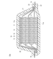
- 1 is a schematic cross-sectional view schematically showing the overall structure of lithium ion secondary batteries stacked in parallel according to an embodiment of the present invention.
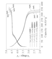
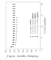
- 1 is a schematic cross-sectional view schematically showing the overall structure of a bipolar lithium ion secondary battery stacked in series according to an embodiment of the present invention. It is drawing which compared the discharge curve at the time of the output characteristic test of each electrode. It is drawing which compared the charging / discharging curve of each electrode under high temperature (50 degreeC). It is drawing which compared the cycling characteristics of each electrode under high temperature (50 degreeC).
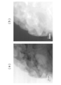
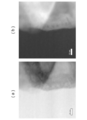
- FIG. 6A is a drawing showing a state observed with an electron microscope (SEM) in the vicinity of the Al 2 O 3 layer-solid solution active material (particle) interface constituting the positive electrode active material particles of the present embodiment.
- FIG. 6B is a drawing showing an XPS observation of the Al 2 O 3 layer-solid solution active material (particle) interface constituting the positive electrode active material particles of the present embodiment.
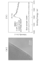
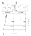
- FIG. 7A is a chart showing an XRD (X-ray diffraction) pattern of the positive electrode active material in which the compositional formula of the solid solution active material is found by elemental analysis.
- FIG. 7B is an enlarged view of the peaks shown in (a) of the two types of patterns (upper and lower figures) in FIG. 7A.
- FIG. 7C is an enlarged view of the peaks shown in (b) of the two types of patterns (upper and lower figures) in FIG. 7A.
- FIG. 8A is a chart showing an XRD (X-ray diffraction) pattern of the positive electrode active material in which the composition formula of the solid solution active material is found by elemental analysis.
- 8B is enlarged and displayed so that the peak shift and shift width of the layered rock salt structure peak (003) of the three types of patterns in FIG. 8A (upper, middle, and lower) can be discriminated. It is the drawing.
- FIG. 8 (c) is enlarged and displayed so that the peak shift and shift width of the layered rock structure peak (101) of the three types of patterns in FIG. 8 (a) (upper, middle and lower) can be discriminated.
- FIG. 8 (d) is enlarged and displayed so that the peak shift and shift width of the layered rock salt structure peak (104) of the three types of patterns in FIG. 8 (a) (upper, middle and lower) can be discriminated.
- FIG. 9A is a drawing showing BF (Bright-field) -STEM Image (bright-field-scanning transmission electron microscope image) of the active material particles.
- FIG. 9B shows a HAADF-STEM Image (high angle scattering dark field-scanning transmission electron microscope image) of the active material particles in the same field of view as FIG. 9A.
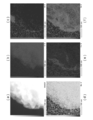
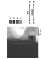
- FIG. 10 is a drawing showing quantitative mapping data by STEM-EDX (scanning transmission electron microscope-energy dispersive X-ray spectroscopy).
- FIG. 9A is a drawing showing BF (Bright-field) -STEM Image (bright-field-scanning transmission electron microscope image) of the active material particles.
- FIG. 9B shows a HAADF-STEM Image (high angle scattering dark field-
- FIG. 10 (a) is the same HAADF-STEM image as FIG. 9 (b).
- FIG. 10B is a diagram showing mapping data of O (upper center) measured in the same field of view as HAADF-STEM (upper left FIG. 10A).
- FIG. 10C is a diagram showing mapping data of Al (upper right) measured in the same field of view as HAADF-STEM (upper left FIG. 10A).
- FIG. 10 (d) is a drawing showing mapping data of Mn (lower left) measured in the same field of view as HAADF-STEM (upper left FIG. 10 (a)).
- FIG. 10 (e) is a diagram showing mapping data of Co (lower center) measured in the same field of view as HAADF-STEM (upper left FIG. 10 (a)).
- FIG. 10 (f) is a diagram showing mapping data of Ni (lower right) measured in the same field of view as HAADF-STEM (upper left FIG. 10 (a)).
- FIG. 11A is a drawing showing BF (Bright-field) -STEM Image (bright-field-scanning transmission electron microscope image) of the active material particles.
- FIG. 11B shows a HAADF-STEM Image (high angle scattering dark field-scanning transmission electron microscope image) of the active material particles in the same field of view as FIG.
- FIG. 11B is the same HAADF-STEM image as in FIG. 11B, and shows areas (four places surrounded by a square frame) for observing the presence (intrusion) of Al element by elemental analysis.
- 4 is a drawing divided by four.
- FIG. 11A is a drawing showing BF (Bright-field) -STEM Image (bright-field-scanning transmission electron microscope image) of the active material particles.
- FIG. 11B shows a HAA
- FIG. 13 (a) is the same HAADF-STEM image as FIG. 12, and is a drawing in which the square frame of the portion to be observed of the element distribution (the portion of the circled number 1 in the image) is indicated by a bold line.
- FIG. 13B is a drawing in which elemental analysis is performed on a portion to be observed of the element distribution of FIG.
- FIG. 14 (a) is the same HAADF-STEM image as FIG. 12, and shows a square frame of a portion to be observed for element distribution (portion 2 of a circled number in the image) by a bold line.
- FIG. 14B is a diagram in which elemental analysis is performed on a portion to be observed of the element distribution of FIG.
- FIG. 15 (a) is the same HAADF-STEM image as FIG.
- FIG. 12 is a drawing in which the square frame of the portion to be observed of the element distribution (the circled portion 3 in the image) is indicated by a bold line.
- FIG. 15B is a drawing in which elemental analysis is performed on a portion to be observed of the element distribution of FIG.
- FIG. 16A is the same HAADF-STEM image as FIG. 12, and shows a square frame of a portion to be observed for element distribution (portion 4 with a circled number in the image) by a bold line.
- FIG. 16B is a drawing in which elemental analysis is performed on a portion to be observed of the element distribution of FIG.
- FIG. 17 is a drawing in which the concentration distribution of Ni, Co, Mn, and Al is expressed by color in the same HAADF-STEM image as FIG. 12 based on the observation results of FIGS.
- One embodiment of the present invention is a positive electrode active material, which is included in a positive electrode active material layer on the surface of a current collector, and the current collector and the positive electrode active material layer constitute a positive electrode.
- a non-aqueous electrolyte secondary battery having a power generation element having the positive electrode, a negative electrode in which a negative electrode active material layer is formed on the surface of the current collector, and an electrolyte layer is configured.
- the positive electrode active material of the present embodiment includes a solid solution active material represented by the following composition formula (1) and an alumina layer on the surface of the solid solution active material, and the solid solution active material and the alumina layer.
- the composition formula (1) is represented by Li 1.5 [Ni a Mn b Co c [Li] d [X] e ] O z .
- the positive electrode active material of the present embodiment the positive electrode including the positive electrode active material, and the nonaqueous electrolyte secondary battery using the positive electrode have the above-described configuration
- the solid solution active material particle surface layer that becomes the most unstable is alumina ( It is stabilized by the penetration of the (coating) layer and the Al element. Therefore, when Mn in the transition metal layer moves to the Li layer due to the activation of the solid solution active material by charging / discharging in the battery using the solid solution active material, the spinel phase is partially transferred to the spinel phase. It is possible to suppress a transition metal that elutes out of the crystal structure without being formed (not immobilized). As a result, battery performance (rate characteristics and charge / discharge capacity) and durability (capacity maintenance ratio) can be improved.
- the nonaqueous electrolyte secondary battery according to the present embodiment is not particularly limited as long as it is a secondary battery using the positive electrode active material of the present embodiment, and typically a lithium ion secondary battery can be mentioned. That is, the non-aqueous electrolyte secondary battery includes the positive electrode of the present embodiment, a negative electrode containing a negative electrode active material capable of inserting and removing lithium ions, and an electrolyte layer interposed between the positive electrode and the negative electrode. .
- a lithium ion secondary battery will be described as an example, but the present invention is not limited to this.
- FIG. 1 is a schematic cross-sectional view schematically showing the overall structure of a lithium ion secondary battery (hereinafter simply referred to as “parallel stacked battery”) stacked in parallel according to an embodiment of the present invention.
- the parallel laminated battery 10a of the present embodiment has a structure in which a substantially rectangular power generation element 17 in which a charge / discharge reaction actually proceeds is sealed inside a laminate film 22 that is a battery exterior material.
- the power generation element 17 is housed and sealed by using a polymer-metal composite laminate film as a battery exterior material and joining all of its peripheral parts by thermal fusion.
- the power generation element 17 includes a negative electrode in which the negative electrode active material layer 12 is disposed on both sides of the negative electrode current collector 11 (only one side for the lowermost layer and the uppermost layer of the power generation element), an electrolyte layer 13, and a positive electrode current collector 14. And a positive electrode in which the positive electrode active material layer 15 is disposed on both sides.
- the negative electrode, the electrolyte layer 13 and the positive electrode are laminated in this order so that one negative electrode active material layer 12 and the positive electrode active material layer 15 adjacent to the negative electrode active material layer 15 face each other with the electrolyte layer 13 therebetween. Yes.
- a positive electrode active material having a specific composition and structure is used for the positive electrode active material layer.
- the adjacent negative electrode, electrolyte layer 13, and positive electrode constitute one single cell layer 16. Therefore, it can be said that the parallel stacked battery 10 of the present embodiment has a configuration in which a plurality of single battery layers 16 are stacked and electrically connected in parallel. Further, a seal portion (insulating layer) (not shown) for insulating between the adjacent negative electrode current collector 11 and the positive electrode current collector 14 may be provided on the outer periphery of the unit cell layer 16. .
- the negative electrode active material layer 12 is disposed only on one side of the outermost layer negative electrode current collector 11 a located in both outermost layers of the power generation element 17.
- the arrangement of the negative electrode and the positive electrode is reversed so that the outermost positive electrode current collector is positioned on both outermost layers of the power generation element 17, and the positive electrode is provided only on one side of the outermost positive electrode current collector.
- An active material layer may be arranged.
- the negative electrode current collector 11 and the positive electrode current collector 14 are attached with a negative electrode current collector plate 18 and a positive electrode current collector plate 19 that are electrically connected to the respective electrodes (negative electrode and positive electrode), and are sandwiched between ends of the laminate film 22. Thus, it has a structure led out of the laminate film 22.
- the negative electrode current collector 18 and the positive electrode current collector 19 are connected to the negative electrode current collector 11 and the positive electrode current collector 14 of each electrode by ultrasonic welding or resistance via a negative electrode terminal lead 20 and a positive electrode terminal lead 21 as necessary. It may be attached by welding or the like (this form is shown in FIG. 1).
- the negative electrode current collector 11 may be extended to form the negative electrode current collector plate 18 and may be led out from the laminate film 22.
- the positive electrode current collector 14 may be extended to form a positive electrode current collector plate 19, which may be similarly derived from the battery exterior material 22.
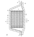
- FIG. 2 is a schematic cross-sectional view schematically showing the overall structure of a serially stacked bipolar lithium ion secondary battery (hereinafter also simply referred to as “series stacked battery”) according to an embodiment of the present invention. is there.
- the series stacked battery 10b shown in FIG. 2 has a structure in which a substantially rectangular power generation element 17 in which a charge / discharge reaction actually proceeds is sealed inside a laminate film 22 that is a battery exterior material.
- the power generation element 17 of the series stacked battery 10 b has a positive electrode active material layer 15 electrically coupled to one surface of the current collector 23, and the surface on the opposite side of the current collector 11.
- a plurality of bipolar electrodes 24 each having a negative electrode active material layer 12 electrically coupled thereto.
- a positive electrode active material having a specific composition and structure is used for the positive electrode active material layer.
- Each bipolar electrode 24 is laminated via the electrolyte layer 13 to form the power generation element 17.
- the electrolyte layer 13 has a configuration in which an electrolyte is held at the center in the surface direction of a separator as a base material.
- the positive electrode active material layer 15 of one bipolar electrode 24 and the negative electrode active material layer 12 of another bipolar electrode 24 adjacent to the one bipolar electrode 24 face each other through the electrolyte layer 13.
- Each bipolar electrode 24 and the electrolyte layer 13 are alternately laminated. That is, the electrolyte layer 13 is sandwiched between the positive electrode active material layer 15 of one bipolar electrode 24 and the negative electrode active material layer 12 of another bipolar electrode 24 adjacent to the one bipolar electrode 24. ing.
- the adjacent positive electrode active material layer 15, electrolyte layer 13, and negative electrode active material layer 12 constitute one unit cell layer 16. Therefore, it can be said that the serially stacked battery 10b of the present embodiment has a configuration in which a plurality of single battery layers 16 are stacked and electrically connected in series. Further, for the purpose of preventing liquid junction due to leakage of the electrolyte from the electrolyte layer 13, a seal portion (insulating portion) 25 is disposed on the outer peripheral portion of the unit cell layer 16.
- the positive electrode active material layer 15 is formed on only one side of the positive electrode outermost layer current collector 23 a located in the outermost layer of the power generation element 17.
- the negative electrode active material layer 12 is formed only on one side of the negative electrode side outermost current collector 23b located in the outermost layer of the power generation element 17.
- the positive electrode active material layer 15 may be formed on both surfaces of the outermost layer current collector 23a on the positive electrode side.
- the negative electrode active material layer 12 may be formed on both surfaces of the outermost current collector 23b on the negative electrode side.
- the positive electrode current collector plate 19 is disposed so as to be adjacent to the outermost layer current collector 23a on the positive electrode side, and this is extended and led out from the laminate film 22 which is a battery exterior material. is doing.
- the negative electrode current collector plate 18 is disposed so as to be adjacent to the outermost layer current collector 23b on the negative electrode side, and similarly, this is extended and led out from the laminate film 22 which is an exterior of the battery.
- the insulating portion 25 is usually provided around each unit cell layer 16.
- the insulating portion 25 is intended to prevent the adjacent current collectors 23 in the battery from contacting each other and the occurrence of a short circuit due to a slight irregularity of the end portions of the unit cell layer 16 in the power generation element 17. Provided. By installing such an insulating portion 25, long-term reliability and safety can be ensured, and a high-quality series stacked battery 10b can be provided.
- the number of times the single cell layer 16 is stacked is adjusted according to the desired voltage. Further, in the serially stacked battery 10b, the number of times the single battery layers 16 are stacked may be reduced if a sufficient output can be ensured even if the battery is made as thin as possible. Even in the case of the serially stacked battery 10b, it is necessary to prevent external impact and environmental degradation during use. Therefore, the power generation element 17 is preferably sealed in a laminate film 22 that is a battery exterior material, and the positive electrode current collector plate 19 and the negative electrode current collector plate 18 are taken out of the laminate film 22.
- the positive electrode active material layer 15 and the positive electrode in FIGS. 1 and 2 include a positive electrode active material having a specific composition and a specific structure, which will be described later.
- the nonaqueous electrolyte secondary battery intended for application to an electric vehicle can achieve high output and high capacity, and the capacity is not easily lowered by repeated charge and discharge.
- each configuration of the nonaqueous electrolyte secondary battery will be described in detail.
- the positive electrode has a function of generating electrical energy by transferring lithium ions together with the negative electrode.
- the positive electrode essentially includes a current collector and a positive electrode active material layer, and the positive electrode active material layer is formed on the surface of the current collector.
- the current collector is made of a conductive material, and a positive electrode active material layer is disposed on one side or both sides thereof.
- a conductive resin in which a conductive filler is added to a metal or a conductive polymer material or a non-conductive polymer material may be employed.
- metals examples include aluminum, nickel, iron, stainless steel (SUS), titanium, and copper.
- a clad material of nickel and aluminum, a clad material of copper and aluminum, or a plating material of a combination of these metals can be preferably used.
- covered on the metal surface may be sufficient.
- aluminum, stainless steel, or copper is preferably used from the viewpoint of conductivity and battery operating potential.
- examples of the conductive polymer material include polyaniline, polypyrrole, polythiophene, polyacetylene, polyparaphenylene, polyphenylene vinylene, polyacrylonitrile, and polyoxadiazole. Since such a conductive polymer material has sufficient conductivity without adding a conductive filler, it is advantageous in terms of facilitating the manufacturing process or reducing the weight of the current collector.
- non-conductive polymer materials include polyethylene (PE; high density polyethylene (HDPE), low density polyethylene (LDPE)), polypropylene (PP), polyethylene terephthalate (PET), polyether nitrile (PEN), polyimide ( PI), polyamideimide (PAI), polyamide (PA), polytetrafluoroethylene (PTFE), styrene-butadiene rubber (SBR), polyacrylonitrile (PAN), polymethyl acrylate (PMA), polymethyl methacrylate (PMMA), Examples include polyvinyl chloride (PVC), polyvinylidene fluoride (PVdF), and polystyrene (PS). Such a non-conductive polymer material may have excellent potential resistance or solvent resistance.
- PE polyethylene
- HDPE high density polyethylene
- LDPE low density polyethylene
- PP polypropylene
- PET polyethylene terephthalate
- PEN polyether nitrile
- PI polyimide
- PAI polyamideimide
- a conductive filler may be added to the conductive polymer material or the non-conductive polymer material as necessary.
- a conductive filler is inevitably necessary to impart conductivity to the resin.
- the conductive filler can be used without particular limitation as long as it is a substance having conductivity.
- metals, conductive carbon, etc. are mentioned as a material excellent in electroconductivity, electric potential resistance, or lithium ion barrier
- the metal is not particularly limited, but at least one metal selected from the group consisting of Ni, Ti, Al, Cu, Pt, Fe, Cr, Sn, Zn, In, Sb, and K, or these metals.
- the conductive carbon is not particularly limited, but is at least one selected from the group consisting of acetylene black, vulcan, black pearl, carbon nanofiber, ketjen black, carbon nanotube, carbon nanohorn, carbon nanoballoon, and fullerene. Preferably it contains seeds.
- the amount of the conductive filler added is not particularly limited as long as it is an amount capable of imparting sufficient conductivity to the current collector, and is generally about 5 to 35% by mass.
- the size of the current collector is determined according to the intended use of the battery. For example, if it is used for a large battery that requires a high energy density, a current collector having a large area is used.
- the thickness of the current collector is not particularly limited, but is usually about 1 to 100 ⁇ m.
- the positive electrode active material layer essentially includes a positive electrode active material having a specific composition and a specific structure.
- the positive electrode active material layer may further include other positive electrode active materials, conductive assistants, binders and other additives.
- the positive electrode active material has a composition capable of releasing lithium ions during charging and occluding lithium ions during discharging.
- the positive electrode active material of the present embodiment has the following composition formula (1):
- X is at least one of Ti, Zr and Nb
- a + b + c + d + e 1.5, 1.1 ⁇ [a + b + c + e] ⁇ 1.4, 0.1 ⁇ d ⁇ 0.4, 0 ⁇ e ⁇ 0.5.
- z has a solid solution active material represented by the number of oxygens satisfying the valence.
- an alumina layer further exists on the particle surface of the solid solution active material, and a region in which Al element exists (invades) on the solid solution active material side of the interface between the solid solution active material particle and the alumina layer is characterized by It is what.
- the solid solution positive electrode material includes electrochemically inactive layered Li 2 MnO 3 and electrochemically active layered LiMO 2 (where [M] is a transition of Co, Ni, Mn, Fe, etc.) Layered lithium-containing transition metal oxides consisting of solid solutions with metals have been studied.
- a solid solution system positive electrode material (Li 2 MnO 3 composition) is activated (a part of the crystal structure is changed into a spinel phase: phase transition). It is necessary to charge up to 4.4 to 4.8V).
- the phase transition to this spinel phase (the LiMnO 2 system generated by the movement of Mn gradually changes into a spinel phase) is caused by the transition metal element (in the crystal structure of the positive electrode active material) constituting the transition metal layer ( It is thought that this is caused by oxidation (for example, Mn 3+ ⁇ Mn 4+ ) (irreversible phase transition by charging).
- the transition metal element involved in the phase transition does not form a spinel phase (is not fixed) and is eluted out of the crystal structure. Further, along with the oxidation of the transition metal, part of the lattice oxygen is released and oxygen gas is also generated. However, the transition metal element is also eluted by the occurrence of oxygen defects in the crystal structure. Furthermore, the transition metal (Mn, etc.) constituting the solid solution active material can be obtained by repeating the charge / discharge cycle in the vicinity of the plateau potential (4.3 to 4.5 V) or by exposing it to a potential in the vicinity of the plateau potential for a long time. ) Elution accompanied by oxidation. Therefore, while the Li 2 MnO 3 composition electrochemically active state, must be suppressed transition metal elution stabilization and Mn or the like of rock salt type layered structure.
- overcharge (resistance) at the end of charge and end of discharge of layered Li 2 MnO 3 is higher than layered LiMO 2 (eg, LiNi 1/2 Mn 1/2 O 2, etc.). It is known that charge / discharge capacity and rate characteristics are degraded. Moreover, since the upper limit potential for use was high (4.3 V or higher), there was a problem that Ni and Mn were easily eluted.
- transition metal elements (Mn, Ni, etc.) constituting the transition metal layer are oxidized in the crystal structure of the positive electrode active material (for example, Mn 3+ ⁇ Mn 4+ ; irreversible phase transition due to charging) and the process in which lattice oxygen is desorbed along with the above. Therefore, when the charge / discharge cycle is repeated near the plateau potential (4.4 to 4.5 V) in order to obtain a high capacity, partial phase transition and oxygen desorption progress gradually. As a result, the average voltage, capacity, and rate characteristics decrease with changes in crystal structure (phase transition and oxygen desorption).
- transition metal element involved in the phase transition does not form a spinel phase (is not fixed), and is eluted outside the crystal structure.
- some of the lattice oxygen is released and oxygen gas is generated with the oxidation of the transition metal.
- the transition metal element is also eluted by oxygen defects in the crystal structure.
- transition metals Mn, Ni, etc. constituting the solid solution active material by being exposed to a fully charged state (potential near the plateau potential) for a long time. Elution occurs as a result of oxidation.
- the elution of the transition metal accompanying the change in the crystal structure of the surface layer also causes a decrease in durability.
- a solid solution active material having an alumina layer coated (covered) with an inorganic material such as Al 2 O 3 (for example, TiO 2 , ZrO 2, etc.) is used as the positive electrode active material.
- the positive electrode active material having such a configuration after the activation treatment at a high potential (for example, 4.4 to 4.8 V) higher than the plateau potential, the charge / discharge cycle (for example, 4.3 to 4.5 V) is performed. Changes in the crystal structure due to repetition can be suppressed.
- a spinel phase is formed when Mn in the transition metal layer moves to the Li layer due to activation and part of the phase transitions to the spinel phase.
- the transition metal (Mn) eluted out of the crystal structure without being fixed (not fixed) is reduced, and the performance and durability can be improved.
- a part of the Al element in the Al 2 O 3 coat (coating) layer penetrates into the surface layer of the active material particles (has a region that exists), thereby strengthening the covalent bond with oxygen.
- the release of lattice oxygen associated with the oxidation of other transition metals is reduced, so that the generation of oxygen gas is reduced, and the generation of oxygen defects in the crystal structure is also reduced.
- the charge / discharge cycle is repeated near the plateau potential (4.3 to 4.5 V), or even when exposed to a potential near the plateau potential for a long period of time, the crystal structure is stabilized and oxygen desorption is reduced.
- the performance and durability can be improved. Furthermore, since the active material particle surface layer (up to 20 nm, further up to 30 nm; FIG. 16 and Example 5) that becomes the most unstable is stabilized by the penetration of the Al 2 O 3 coat and the Al element, As described above, the performance and durability can be further improved as compared with the Al 2 O 3 coating technique in which the entry (presence) of Al element is difficult in the surface layer of the active material particles.
- FIG. 3 is a drawing for comparing discharge curves during the output characteristic test of each electrode (positive electrode).
- an output characteristic test was performed under the same conditions with a battery using two types of electrodes (positive electrodes).
- a positive electrode using a solid solution active material not coated with alumina as a positive electrode active material (bare sample; Comparative Example 1), and a positive electrode active material (5 wt% Al 2 O 3 coating) provided with a 5 mass% alumina layer on the surface of the solid solution active material
- a battery using the positive electrode used in Example 4 was used.
- any solid solution active material one represented by the composition formula of Example 1; Li 1.5 [Ni 0.40 Mn 0.60 Co 0.40 [Li] 0.1 ] O z was used.
- a battery using each positive electrode produced using these positive electrode active materials was tested by changing the discharge rate characteristics.
- the laminate type battery of Comparative Example 1 was used as a battery using a positive electrode using a solid solution active material not coated with alumina as a positive electrode active material.
- the laminate type battery of Example 4 was used as a battery using a positive electrode using a solid solution active material surface provided with a 5 mass% alumina layer.
- the discharge test conditions in FIG. 3 were the initial charge treatment, gas removal treatment 1, activation treatment, and gas removal treatment 2 as the evaluation of the battery characteristics of Example 1. Thereafter, the performance evaluation was changed from the 0.1C rate to the 0.05C, 0.1C, 0.2C, 0.5C, 1.0C, and 2.0C rates shown in FIG. The discharge curve was obtained.
- FIG. 4 is a drawing comparing the charge / discharge curves of each electrode (positive electrode) at a high temperature (50 ° C.).
- a battery using four types of electrodes (positive electrode) was subjected to a charge / discharge test under the same conditions.
- a battery using a positive electrode using 2 O 3 coating was used.
- any solid solution active material one represented by the composition formula of Example 1; Li 1.5 [Ni 0.40 Mn 0.60 Co 0.40 [Li] 0.1 ] O z was used.
- the laminate type battery of Comparative Example 1 was used as a battery using a positive electrode using a solid solution active material not coated with alumina as a positive electrode active material.
- the laminate type battery of Example 3 was used as a battery using a positive electrode using a positive electrode active material in which a 2 mass% alumina layer was provided on the surface of the solid solution active material.
- the laminate type battery of Example 4 was used as a battery using a positive electrode using a positive electrode active material in which a 5 mass% alumina layer was provided on the surface of the solid solution active material.
- the laminated battery of Example 5 was used as a battery using a positive electrode using a positive electrode active material having a 10 mass% alumina layer provided on the surface of the solid solution active material.
- the charge / discharge test conditions in FIG. 4 are as follows: after the initial charge process, the gas removal process 1, the activation process, and the gas removal process 2 were performed as the evaluation of the battery characteristics of Example 1, the performance evaluation was performed from room temperature to a high temperature (50 C.) The same procedure as in Example 1 except that the temperature was changed to below.
- FIG. 5 is a drawing comparing the cycle characteristics of each electrode (positive electrode) at a high temperature (50 ° C.).
- a battery using four types of electrodes (positive electrodes) was subjected to a charge / discharge cycle test under the same conditions.
- a battery using a positive electrode using 2 O 3 coating was used.
- any solid solution active material one represented by the composition formula of Example 1; Li 1.5 [Ni 0.40 Mn 0.60 Co 0.40 [Li] 0.1 ] O z was used.
- the laminate type battery of Comparative Example 1 was used as a battery using a positive electrode using a solid solution active material not coated with alumina as a positive electrode active material.
- the laminate type battery of Example 3 was used as a battery using a positive electrode using a positive electrode active material in which a 2 mass% alumina layer was provided on the surface of the solid solution active material.
- the laminate type battery of Example 4 was used as a battery using a positive electrode using a positive electrode active material in which a 5 mass% alumina layer was provided on the surface of the solid solution active material.
- the laminated battery of Example 5 was used as a battery using a positive electrode using a positive electrode active material having a 10 mass% alumina layer provided on the surface of the solid solution active material.
- the cycle characteristic test conditions in FIG. 5 are the same as those in Example 1 except that the initial charge process, the gas removal process 1, the activation process, the gas removal process 2, and the performance evaluation are performed, and then the life evaluation is performed in Example 1. And cycle characteristics were obtained.
- the transition metal (from the crystal structure of the surface layer) is formed by coating Al 2 O 3 (inorganic matter such as TiO 2 and ZrO 2 ) (that is, providing an alumina layer (inorganic layer such as titania layer, zirconia layer)). Elution of Mn 4+ , Ni 2+ ) and oxygen desorption can be suppressed. Furthermore, by forming an (Al—Li) compound at the interface between the Al 2 O 3 layer and the solid solution active material (providing a region where Al element exists on the active material side), the Li diffusibility (Li conductivity) is improved. Can be achieved. As a result, not only the interface resistance is reduced, but also the intra-particle Li diffusion resistance can be reduced.
- battery performance (capacity, rate characteristics, cycle characteristics) can be improved as shown in FIGS. Further, by suppressing the elution of the transition metal, it is possible to suppress the reaction between the solid solution active material (particle) surface layer and the electrolytic solution, and it is possible to suppress the decrease in the average voltage with the progress of the cycle.
- each of these peak shifts is (003) shifted to the low angle side and (101) shifted to the high angle side with respect to the layered rock salt structure peak in the X-ray diffraction of only the solid solution active material, (104) is preferably shifted to the high angle side.
- each peak shift width is (003): ⁇ 0.08 ° ⁇ ⁇ ⁇ 0.00 °, (101): 0.00 ° with respect to the layered rock salt structure peak in the X-ray diffraction of only the solid solution active material.
- ⁇ ⁇ 0.05 °, (104): 0.00 ° ⁇ ⁇ 0.05 ° is preferable.
- LiMO 2 shows a layered rock salt structure (rock salt type layered structure) as an XRD (X-ray diffraction) peak.
- Li 2 MnO 3 has a superlattice diffraction peak at 20-23 °, but otherwise exhibits the same layered rock salt structure (rock salt type layered structure) as LiMO 2 . Therefore, the solid solution active material of Li 2 MnO 3 and LiMO 2 exhibits a layered rock salt structure (rock salt type layered structure) in which a superlattice diffraction peak exists at 20-23 °.
- LiMnO 2 is present as an impurity from the beginning, or active at a high potential (for example, 4.4 to 4.8 V) higher than the plateau potential.
- a high potential for example, 4.4 to 4.8 V
- a change is observed in a part of the crystal structure.
- the charge / discharge cycle for example, 4.3 to 4.5 V
- LiMnO 2 that is present as an impurity or generated as part of the crystal structure is changed.
- the XRD diffraction peak characteristic of the spinel phase appears gradually changing to the spinel phase.
- the layered rock salt structure has a shift as described above, so that a high potential (for example, 4.4 to After the activation treatment at 4.8 V), it is possible to suppress a change in crystal structure due to repeated charge / discharge cycles (for example, 4.3 to 4.5 V).
- the active material particle surface layer ( ⁇ 20 nm), which becomes the most unstable by having the peak shift in the above-mentioned range in (003), (101) and (104), is composed of an Al 2 O 3 coat and an Al element. Stabilizes by intrusion (presence). Therefore, the performance and durability can be further improved as compared with the conventional Al 2 O 3 coating technique in which the entry (presence) of Al element into the surface layer of the active material particles is difficult.
- the Al element of the Al 2 O 3 coat layer does not enter and replace the particles (bulk). Since the Li insertion / desorption associated with the oxidation / reduction of Ni or Mn is not inhibited, a high capacity can be obtained.
- the analyzer includes XPS (X-ray photoelectron spectroscopy), TEM-EDX (transmission electron microscope-energy dispersive X-ray spectroscopy), STEM-EDX / EELS (scanning transmission electron microscope-energy dispersion). Type X-ray spectroscopy / electron energy loss spectrometer), HAADF-STEM (high angle scattering dark field-scanning transmission electron microscope image), and the like can be used.
- XPS X-ray photoelectron spectroscopy
- TEM-EDX transmission electron microscope-energy dispersive X-ray spectroscopy
- STEM-EDX / EELS scanning transmission electron microscope-energy dispersion
- Type X-ray spectroscopy / electron energy loss spectrometer HAADF-STEM (high angle scattering dark field-scanning transmission electron microscope image), and the like can be used.
- An analysis example of the presence of Al element in the surface layer of the active material particles using the various analyzers shown below is shown.
- FIG. 6A shows the positive electrode active material particles of this embodiment.
- 2 is a diagram showing a state observed with an electron microscope (SEM) in the vicinity of an interface between an Al 2 O 3 layer and a solid solution active material (particles).
- FIG. 6B is a drawing showing an XPS observation of the Al 2 O 3 layer-solid solution active material (particle) interface constituting the positive electrode active material particles of the present embodiment.
- Example 6A the sample (2 wt% Al 2 O 3 coated sample) provided with a 2 mass% alumina layer on the surface of the solid solution active material, which is the positive electrode active material manufactured in Example 3, was used.
- FIG. 6B a sample (bare sample) prepared using the solid solution active material not coated with alumina prepared in Comparative Example 1 as a positive electrode active material was used.
- the positive electrode active material sample provided with a 2 mass% alumina layer on the surface of the solid solution active material prepared in Example 3 is an alumina layer (thickness 10 nm; see Example 3 in Table 1) from FIG.
- Argon etching was performed from 15 to 20 nm in the depth direction from the surface.
- the element distribution in the surface layer (depth direction: 5 to 10 nm) on the active material side of the Al 2 O 3 layer-solid solution active material (particle) interface can be known.
- any solid solution active material represented by the composition formula of Example 1; Li 1.5 [Ni 0.40 Mn 0.60 Co 0.40 [Li] 0.1 ] O z is used. It was.
- an Al 2 O 3 layer formed on the surface of the solid solution active material particles (the dense portion in the dense state on the left side of the figure) in a range in which two straight lines are drawn. Can be confirmed. Since the Al 2 O 3 layer portion is formed by bonding Al 2 O 3 particles to each other and is layered, the Al 2 O 3 layer portion can be visually recognized as a relatively shaded portion in a granular state. From FIG. 6 (b), in the X-ray photoelectron spectroscopy spectrum of the solid solution active material sample (bare sample) not coated with alumina, no photoelectron peak is observed in the range of photoelectron energy (horizontal axis) 1550 to 1570 eV. Al element was not observed.
- the surface layer on the active material side of the Al 2 O 3 layer-solid solution active material (particle) interface As an element distribution in the depth direction (5 to 10 nm), a strong peak of Al (1s) could be observed in the vicinity of 1562 eV. From this, it can be confirmed that the Al element is present in the surface layer (depth direction; 5 to 10 nm) on the active material side of the Al 2 O 3 layer-solid solution active material (particle) interface.
- FIG. 7A is a chart showing an XRD (X-ray diffraction) pattern of the positive electrode active material in which the compositional formula of the solid solution active material is found by elemental analysis.
- FIG. 7A shows a chart showing an XRD (X-ray diffraction) pattern of a sample (Bare sample) using a solid solution active material not coated with alumina as a positive electrode active material.
- Example 1 Li 1.5 [Ni 0.40 Mn 0.60 Co 0.40 [Li] 0.1 ] O z was used.
- the positive electrode active material produced in Comparative Example 1 was used as a sample (Bare sample) using a solid solution active material not coated with alumina as a positive electrode active material.
- FIG. 7B is an enlarged view of the peaks shown in (a) of the two types of patterns (upper and lower figures) in FIG. 7A.
- FIG. 7C is an enlarged view of the peaks shown in (b) of the two types of patterns (upper and lower figures) in FIG. 7A.
- FIG. 8A is a chart showing an XRD (X-ray diffraction) pattern of the positive electrode active material in which the composition formula of the solid solution active material is found by elemental analysis.
- FIG. 8A shows a chart showing an XRD (X-ray diffraction) pattern of a sample (Bare sample) using a solid solution active material not coated with alumina as a positive electrode active material. Also shown in the middle figure chart showing an XRD (X-ray diffraction) pattern of the positive electrode active material sample having a 2 wt% alumina layer on the same solid solution active material (particles) surface and below (2wt% Al 2 O 3 coated sample) .
- Example 1 Li 1.5 [Ni 0.40 Mn 0.60 Co 0.40 [Li] 0.1 ] O z was used.
- the positive electrode active material produced in Comparative Example 1 was used as a sample (Bare sample) using a solid solution active material not coated with alumina as a positive electrode active material.
- FIG. 8B is enlarged and displayed so that the peak shift and shift width of the layered rock salt structure peak (003) of the three types of patterns in FIG. 8A (upper, middle, and lower) can be discriminated. It is the drawing.
- FIG. 8 (c) is enlarged and displayed so that the peak shift and shift width of the layered rock salt structure peak (101) of the three types (upper, middle and lower) patterns in FIG.
- FIG. 8 (a) can be discriminated. It is the drawing.
- FIG. 8 (d) is enlarged and displayed so that the peak shift and shift width of the layered rock structure peak (104) of the three types of patterns in FIG. 8 (a) (upper, middle and lower) can be discriminated. It is the drawing. Further, XRD (X-ray diffraction) shown in FIG. 8 is measured by powder X-ray diffraction using Rigaku, Ultimate III, radiation source: CuK ⁇ .
- peaks were observed in the layered rock salt structure peaks (003), (101), and (104).
- the sample of the solid solution active material (Bare sample) shown in the lower figure is provided with the alumina layer shown in the middle and upper figures, and the layered rock salt structure peak (003) ( A slight peak shift was observed in any of (101) and (104). This suggested that the Al 2 O 3 layer on the surface of the solid solution active material was not simply covered. More specifically, (003) is shifted to the lower angle side from FIG. 8 (b), (101) is shifted to the higher angle side from FIG. 8 (c), and (104) is shifted from FIG. It can be observed to shift to the high angle side.
- the peak shift width depends on the Al 2 O 3 coating amount, and (003) shifts to the low angle side in the range of ⁇ 0.08 ° ⁇ ⁇ ⁇ 0.00 °, and (101) It is observed that the angle shifts to the high angle side in the range of 0.00 ° ⁇ ⁇ 0.05 °, and (104) shifts to the high angle side in the range of 0.00 ° ⁇ ⁇ ⁇ 0.05 °. (See FIGS. 8B, 8C, and 8D). From the above, it is considered that a part of the compound is generated (or solid solution) at the interface portion between the alumina layer and the solid solution active material (particles). As a result, as can be seen from Table 1 of the examples, it was confirmed that the effect of improving the performance and durability was greatly enhanced by the remarkable increase in the effect of preventing the elution of transition metals (Mn and the like).
- FIG. 9A shows BF (Bright-field) -STEM Image (bright field) of active material particles. -Scanning transmission electron microscope image).
- FIG. 9B is a drawing showing a HAADF-STEM Image (high angle scattering dark field-scanning transmission electron microscope image) of the active material particles in the same field of view as FIG. 9A.
- the object of measurement was positive electrode active material particles (secondary particles) of Example 3 prepared by coating the solid solution active material (particles) surface with 2% by mass of alumina having an active material particle (secondary particle) size of about 2 ⁇ m.
- FIG. 10 is a drawing showing quantitative mapping data by STEM-EDX (scanning transmission electron microscope-energy dispersive X-ray spectroscopy).
- FIG. 10 (a) is the same HAADF-STEM image as FIG. 9 (b).
- FIG. 10B is a diagram showing mapping data of O (upper center) measured in the same field of view as HAADF-STEM (upper left FIG. 10A).
- FIG. 10C is a diagram showing mapping data of Al (upper right) measured in the same field of view as HAADF-STEM (upper left FIG. 10A).
- FIG. 10 is a drawing showing quantitative mapping data by STEM-EDX (scanning transmission electron microscope-energy dispersive X-ray spectroscopy).
- FIG. 10 (a) is the same HAADF-STEM image as FIG. 9 (b).
- FIG. 10B is a diagram showing mapping data of O (upper center) measured in the same field of view as HAADF-STEM (upper left FIG. 10A).
- FIG. 10 (d) is a drawing showing mapping data of Mn (lower left) measured in the same field of view as HAADF-STEM (upper left FIG. 10 (a)).
- FIG. 10 (e) is a diagram showing mapping data of Co (lower center) measured in the same field of view as HAADF-STEM (upper left FIG. 10 (a)).
- FIG. 10 (f) is a diagram showing mapping data of Ni (lower right) measured in the same field of view as HAADF-STEM (upper left FIG. 10 (a)).
- a bright-field (BF) STEM image formed using an electron beam transmitted through a sample and a dark field formed using an electron beam scattered from the sample
- DF dark-field
- FIG. 9A the transmission composition showing the internal structure of the sample, as in the case of a normal TEM image
- HAADF high angle scattering annular dark field
- Z atomic number
- a substance with a large atomic number appears bright (see FIGS. 9B, 11B, and 12A to 25A).
- HAADF-STEM High Angle Scattering Circular Dark Field Scanning Transmission Microscopy
- the image is applied by operating a thinly focused electron beam while operating the sample, and the scattered electrons are detected at a high angle by a ring detector. can get. Since a material having a large Z 2 ⁇ is scattered at a higher angle, heavier elements are darker in the STEM image and brighter in the HAADF-STEM image. Since a contrast proportional to the atomic weight (Z) is obtained, it is also called a Z contrast image.
- STEM-EDX quantitative mapping characteristic X-rays generated from each point are taken into an EDS (Energy-Dispersive-Spectroscope) detector while narrowing down the electron beam and scanning the sample, thereby obtaining information on the composition distribution of the sample. Can be obtained.
- EDS Electronic-Dispersive-Spectroscope
- FIG. 11A shows BF (Bright-field) -STEM Image (bright field— It is drawing which shows a scanning transmission electron microscope image.
- FIG. 11B is a drawing showing a HAADF-STEM Image (high angle scattering dark field-scanning transmission electron microscope image) of the active material particles in the same field of view as FIG.
- the object of measurement was the solid solution active material-alumina layer interface of the positive electrode active material particles (primary particles) of Example 3 prepared by coating 2% by mass of alumina on the surface of the solid solution active material, particularly the surface layer on the solid solution active material side.
- the element distribution was the object of observation.
- FIG. 11B the whitish side (right side) is an alumina layer, and the black part (left side) is a solid solution active material.
- FIG. 12 is the same HAADF-STEM image as FIG. 11 (b), and the regions (four places surrounded by a square frame) for observing the presence (intrusion) of Al element by elemental analysis are circled in the image. It is a drawing divided by the numbers 1 to 4.
- FIG. 13 (a) is the same HAADF-STEM image as FIG.
- FIG. 12 is a drawing in which the square frame of the portion to be observed of the element distribution (the portion of the number 1 in the image) is indicated by a bold line.
- FIG. 13B is a drawing in which elemental analysis is performed on a portion to be observed of the element distribution of FIG.
- the thickness of the alumina layer is about 10 to 20 nm, and the observation object is outside the alumina layer.
- FIG. 14 (a) is the same HAADF-STEM image as FIG. 12, and is a drawing in which the square frame of the portion to be observed for the element distribution (the circled portion 2 in the image) is indicated by a bold line.
- FIG. 14B is a diagram in which elemental analysis is performed on a portion to be observed of the element distribution of FIG.
- the Al element peak could be observed in the part 2 of the circled number in FIG. 14 (a), which is the part to be observed for the element distribution.
- the alumina layer is composed of lighter elements having smaller atomic numbers than the solid solution active material, and is located in the dark part. Considering the distance from the active material-alumina layer interface (the interface between the white region and the black region) in FIG. 14A, the thickness of the alumina layer is about 10 to 20 nm, so the observed portion is the alumina layer. I understand that.
- FIG. 15 (a) is the same HAADF-STEM image as FIG. 12, and is a drawing in which the square frame of the portion to be observed of the element distribution (the circled portion 3 in the image) is indicated by a bold line.
- FIG. 15B is a drawing in which elemental analysis is performed on a portion to be observed of the element distribution of FIG.
- the Al element peak could be observed at the portion 3 of the circled number in FIG. 15 (a), which is the portion to be observed for the element distribution.
- the circled number 3 indicates the solid solution activity from the active material-alumina layer interface considering the distance from the active material-alumina layer interface (the interface between the white region and the black region). This is the region (5 to 10 nm) of the outermost layer of the substance particles. Since Al element was observed in this region, it can be seen that Al element exists (invades) from the active material-alumina layer interface to the active material side.
- FIG. 16 (a) is the same HAADF-STEM image as FIG. 12, and is a drawing in which the square frame of the portion to be observed of the element distribution (the circled portion 4 in the image) is indicated by a bold line.
- FIG. 16B is a drawing in which elemental analysis is performed on a portion to be observed of the element distribution of FIG.
- FIG. 25 is a drawing in which the concentration distributions of Ni, Co, Mn, and Al are expressed by color in the same HAADF-STEM image as FIG. 12 based on the observation results of FIGS.
- the Al element peak could be observed even in the circled portion 4 in FIG.
- the Al concentration is decreasing.
- the HAADF-STEM image in FIG. 16A shows the circled number 4 in consideration of the distance from the active material-alumina layer interface (the interface between the white region and the black region).
- the region (10 to 20 nm) below the outermost layer of the solid solution active material particles To the region (10 to 20 nm) below the outermost layer of the solid solution active material particles. Since Al element was also observed in this region, it can be seen that Al element exists (invades) from the active material-alumina layer interface to the surface layer (about 20 nm) on the active material side. 15B and 16B, since the Al concentration is lower than the outermost layer of the active material, the outermost layer has the highest concentration as shown in FIG.
- the alumina (Al 2 O 3 ) coat layer is distributed on the surface of the solid solution active material particles (see FIGS. 6a and 10).
- Al element penetrates (exists) from the surface of the solid solution active material particles to about 10 to 20 nm.
- the penetration depth although it depends on the thickness (coating amount) of the alumina layer, it can be seen that it can penetrate (exist) up to about 30 nm (see Example 19 in Table 1).
- the Al element was present regardless of the low firing temperature (400 to 450 ° C.) after coating alumina on the surface of the solid solution active material particles. It can be confirmed that solid solution (or Al.Li-containing compound formation) is formed in the surface layer portion of the solid solution active material. However, although the Al ⁇ Li-containing compound that is solid-solved in the surface layer portion cannot be specified, it seems to be close to LiAlO 2 . That is, an Al 2 O 3 layer is present on part or all of the surface of the solid solution active material particles (substantially all from FIG. 6a), and the surface layer of the solid solution active material particles (up to 20 nm, further up to 35 nm; In Example 19), an Al element penetrates.
- the positive electrode active material of this embodiment has a solid solution active material represented by the composition formula (1); Li 1.5 [Ni a Mn b Co c [Li] d [X] e ] O z .
- LiMO 2 shows a rock salt type layered structure as an X-ray diffraction (XRD) peak.
- Li 2 MnO 3 has a superlattice diffraction peak at 20-23 °, but other than that shows the same rock salt type layered structure as LiMO 2 . Therefore, the solid solution system of Li 2 MnO 3 and LiMO 2 shows a rock salt type layered structure in which a superlattice diffraction peak exists at 20-23 °. That is, the positive electrode active material of the composition formula (1) has a plurality of specific diffraction peaks in the X-ray diffraction (XRD) measurement.
- XRD X-ray diffraction
- the positive electrode active material having the above composition formula is a solid solution system of Li 2 MnO 3 and LiMnO 2 , and among the plurality of diffraction peaks, the diffraction peak at 20-23 ° is a superlattice diffraction peak characteristic of Li 2 MnO 3. It is. Usually, the diffraction peaks at 36.5-37.5 ° (101), 44-45 ° (104) and 64-65 (108) / 65-66 (110) are the rock salt type layered structure of LiMnO 2. Is characteristic.
- the solid solution active material of the present embodiment does not include those having a peak other than a diffraction peak showing a rock salt type layered structure, for example, other peaks derived from impurities, in these angular ranges.
- a structure other than the rock salt type layered structure is included in the solid solution active material. The effect of improving the cycle characteristics of the present embodiment can be surely obtained if the structure other than the rock salt type layered structure is not included.
- the solid solution active material represented by the composition formula (1) of the present embodiment at least one of Ti, Zr and Nb substitutes Mn 4+ in the transition metal layer made of Ni, Co and Mn.
- the valence e of X in the general formula (1) may be greater than 0, that is, it may include at least one of Ti, Zr, and Nb corresponding to X in the general formula (1) ( See Examples 14-19).
- a solid solution in which a part of Mn is substituted with Ti, Zr, or Nb is activated at a high potential (for example, 4.4 to 4.8 V) higher than a plateau potential, and then charged and discharged (for example, 4 .3 to 4.5 V) can be prevented from changing the crystal structure.
- Elements such as Ti, Zr, and Nb dissolve in the transition metal layer to replace Mn4 +, and as a result of activation, Mn in the transition metal layer moves to the Li layer and part of it enters the spinel phase.
- the transition metal such as Mn
- the transition metal eluted out of the crystal structure without forming a spinel phase (not fixed) is reduced, and the performance and durability can be improved.
- a solid solution whose surface is coated with an inorganic substance such as Al 2 O 3 is active at a high potential (eg, 4.4 to 4.8 V) higher than the plateau potential.
- an inorganic substance such as Al 2 O 3 (eg, TiO 2 , ZrO 2, etc.)
- a high potential eg, 4.4 to 4.8 V
- changes in the crystal structure due to repeated charge / discharge cycles for example, 4.3 to 4.5 V
- Mn in the transition metal layer moves to the Li layer and part of the phase transitions to the spinel phase, so that no spinel phase is formed ( Transition metal (Mn) that elutes out of the crystal structure is reduced (not fixed), and performance and durability can be improved.
- the Al elements in the Al 2 O 3 coating (coating) layer penetrate into the surface layer of the active material particles, the covalent bond with oxygen is strengthened, so that the lattice oxygen is released due to oxidation of other transition metals. Therefore, the generation of oxygen gas is reduced, and the generation of oxygen defects in the crystal structure is also reduced.
- the active material particle surface layer ( ⁇ 35 nm) that becomes most unstable is stabilized by the penetration of the Al 2 O 3 coat and Al element. Therefore, the performance and durability can be further improved as compared with the conventional Al 2 O 3 coating technique in which the entry (presence) of Al element into the surface layer of the active material particles is difficult. Since the Al element in the Al 2 O 3 coat layer does not enter and replace the particles (bulk), Li insertion / desorption associated with oxidation and reduction of Ni and Mn in the bulk is not inhibited, and thus high capacity can be obtained.
- the diffraction peak indicating the rock salt type layered structure of the solid solution active material is on the low angle side.
- a shift is preferred. That is, the solid solution active material of the above composition formula (1) containing at least one kind of Ti, Zr and Nb is 20-23 °, 35.5-36.5 ° (101) in X-ray diffraction (XRD) measurement. ) Preferably having diffraction peaks at 43.5-44.5 ° (104) and 64-65 ° (108) / 65-66 ° (110).
- the shift of the diffraction peak to the lower angle side indicates that Ti or the like is more solid-dissolved in the solid solution active material of the above composition formula (1) and is replacing Mn. Conceivable.
- the solid solution active material of the composition formula (1) when at least one kind composed of Ti, Zr and Nb is included, Ti or the like is contained in the transition metal layer of the solid solution active material of the composition formula (1).
- Mn 4+ for solid solution, the covalent bond between the substituting element and oxygen is strengthened, and the release of oxygen in the crystal lattice accompanying the oxidation of the transition metal can be reduced. Thereby, generation of oxygen gas can be suppressed, and oxygen defects in the crystal structure can be reduced.
- a + b + c + e satisfies 1.1 ⁇ [a + b + c + e] ⁇ 1.4.
- nickel (Ni), cobalt (Co), and manganese (Mn) are known to contribute to capacity and output characteristics from the viewpoint of improving the purity of the material and improving the electronic conductivity.
- Ti or the like partially substitutes Mn in the crystal lattice.
- 1.1 ⁇ [a + b + c + e] ⁇ 1.2 each element can be optimized and the capacity and output characteristics can be further improved. Therefore, when a positive electrode active material that satisfies this relationship is used in a lithium ion secondary battery, it is possible to exhibit excellent initial charge / discharge efficiency while maintaining high capacity by maintaining high reversible capacity. Become.
- a is preferably 0 ⁇ a ⁇ 1.5, and more preferably 0.1 ⁇ a ⁇ 0.75.
- a is in the above range, a secondary battery having a better capacity retention rate can be obtained.
- a is not a ⁇ 0.75, the crystal structure is not stabilized because nickel is contained in the positive electrode active material within the above range d on condition that nickel (Ni) is divalent. There is.
- a ⁇ 0.75 the crystal structure of the positive electrode active material tends to be a rock salt type layered structure.
- b is preferably 0 ⁇ b ⁇ 1.5, and more preferably 0.2 ⁇ b ⁇ 0.9.
- b is in the above range, a secondary battery having a better capacity retention rate can be obtained.
- manganese is contained in the positive electrode active material within the above range d, provided that manganese is tetravalent, and nickel (Ni) is further contained in the positive electrode active material. Due to the inclusion, the crystal structure may not be stabilized.
- b ⁇ 0.9 the crystal structure of the positive electrode active material tends to be a rock salt type layered structure.
- c is preferably 0 ⁇ c ⁇ 1.5.
- nickel and manganese are contained in the positive electrode active material within the above range d on condition that cobalt is trivalent.
- cobalt (Co) is contained in the positive electrode active material within the above range d on condition that nickel (Ni) is divalent and manganese (Mn) is tetravalent. Therefore, the crystal structure of the positive electrode active material may not be stabilized.
- c ⁇ 0.6 the crystal structure of the positive electrode active material tends to be a rock salt type layered structure.
- composition formula (1) 0.1 ⁇ d ⁇ 0.4.
- d is not 0.1 ⁇ d ⁇ 0.4, the crystal structure of the positive electrode active material may not be stabilized.
- the positive electrode active material tends to have a rock salt type layered structure.
- the range of d is more preferably 0.15 ⁇ d ⁇ 0.35.
- d is 0.1 or more, the composition is less likely to be close to Li 2 MnO 3 and charge / discharge is facilitated, which is preferable.
- composition formula (1) 0 ⁇ e ⁇ 0.5.
- at least one of Ti, Zr and Nb can sufficiently substitute Mn 4+ so that elution is suppressed. From this viewpoint, it is preferably 0.02 ⁇ e ⁇ 0.5, more preferably 0.05 ⁇ e ⁇ 0.3.
- e 0, the operational effects of the present embodiment can be sufficiently obtained (see the comparison between Examples 1 to 13 and Examples 14 to 19).
- the ionic radius of each element is Ti 4+ 0.61 0.6, Zr 4+ 0.72 ⁇ , and Nb 5+ 0.64 ⁇ with respect to Mn 4+ 0.54 ⁇ , and Ti, Zr, and Nb are larger than Mn. Therefore, as Mn 4+ in the positive electrode active material is replaced with Ti or the like, the crystal lattice expands, and the diffraction peak indicating the rock salt type layered structure shifts to a lower angle side. On the contrary, if the diffraction peak is shifted to a lower angle side, the substitution amount of Mn 4+ such as Ti is larger, and the crystal structure is easily stabilized. That is, the elution of Mn at the time of charge / discharge is further suppressed, and the capacity reduction of the secondary battery can be more effectively prevented.
- the specific surface area of the solid solution active material is preferably 0.2 to 0.6 m 2 / g, and more preferably 0.25 to 0.5 m 2 / g.
- a specific surface area of 0.2 m 2 / g or more is preferable because sufficient battery output can be obtained.
- the specific surface area is 0.6 m 2 / g or less because elution of manganese can be further suppressed.
- the value of the specific surface area is a value measured using a measuring apparatus: BELSORP-miniII manufactured by Nippon Bell.
- the average particle size of the solid solution active material is preferably 10 to 20 ⁇ m, and more preferably 12 to 18 ⁇ m. It is preferable that the average particle size is 10 ⁇ m or more because elution of manganese can be suppressed. On the other hand, when the average particle size is 20 ⁇ m or less, it is possible to coat alumina to every corner of the primary particle surface constituting the secondary particles in the alumina coating at the time of producing the positive electrode active material. Further, it is preferable because foil breakage, clogging, and the like can be suppressed in the coating step on the current collector during the production of the positive electrode.
- the average particle diameter is measured by a laser diffraction / scattering particle size distribution measuring device. The average particle diameter can be measured using, for example, a particle size distribution analyzer (model LA-920) manufactured by Horiba.
- the positive electrode active material of the present embodiment includes a solid solution active material of the above composition formula (1), (a) an alumina layer is present on the surface of the solid solution active material, and (b) the solid solution active material and the alumina layer. A region in which an Al element is present on the solid solution active material side of the interface.
- the spinel phase is not formed (not fixed) in the partial spinel phase transition accompanying the activation of the solid solution active material. ), Transition metals eluting out of the crystal structure are reduced, and performance and durability can be improved.
- an alumina layer exists on the surface of the solid solution active material (particles) of the composition formula (1).
- an alumina coating layer is further present on the surface of the solid solution active material, thereby reducing lattice oxygen detachment associated with oxidation of the transition metal. The generation of oxygen gas is reduced, and the generation of oxygen defects in the crystal structure is also reduced.
- the alumina layer is 50% or more of the particle surface of the solid solution active material, preferably 60% or more, more preferably 70% or more, still more preferably 80% or more, particularly preferably 90% or more, and most preferably the entire surface ( It is desirable to cover approximately 100%; approximately 97 to 98%).
- the above-mentioned effect can be improved further.
- 50% or more of the particle surface of the solid solution active material, or even the entire surface (approximately 100). %; Approximately 97 to 98%) (see FIG. 6 (a)).
- the average thickness of the alumina layer is in the range of 1 to 60 nm, preferably 2 to 55 nm, more preferably 3 to 30 nm, still more preferably 3 to 20 nm, and particularly preferably 5 to 15 nm. If the average thickness of the alumina layer is within the above range, the generation of oxygen gas is reduced and the generation of oxygen defects in the crystal structure is reduced due to the reduction of lattice oxygen desorption due to transition metal oxidation. .
- the charge / discharge cycle is repeated near the plateau potential or exposed to a potential near the plateau potential for a long period of time, elution due to oxidation of transition metals (Mn, Ni, etc.) constituting the solid solution active material is suppressed, Since oxygen desorption is also reduced, performance and durability are improved.
- the average thickness of the Al 2 O 3 layer disposed on the surface of the solid solution active material particles is 1 nm or more, particularly 3 or more, the durability improving effect by the Al 2 O 3 coating layer is sufficiently obtained. Further, if the average thickness of the Al 2 O 3 layer is 60 nm or less, particularly 20 nm or less, the Li ions easily move and a performance improvement effect is sufficiently obtained.
- the measurement method of the average thickness of an alumina layer can be performed with the observation image of SEM or TEM, for example.
- the average particle size of the solid solution active material described above, the average particle size of the positive electrode active material provided with the alumina layer, and the particle size distribution measuring device of the laser diffraction / scattering method are measured, and the difference between them is the average of the alumina layer It may be a thickness.
- the content of the alumina is 0.1 to 12% by mass, preferably 0.3 to 10% by mass, more preferably 0.5 to 7% by mass, further based on the total amount of the positive electrode active material.
- the range is preferably 0.5 to 5% by mass, particularly preferably 1 to 5% by mass. If the content of the alumina is within the above range, the release of lattice oxygen accompanying the oxidation of the transition metal is reduced, so that the generation of oxygen gas is reduced and the generation of oxygen defects in the crystal structure is also reduced.
- alumina (Al 2 O 3 ) Even if the charge / discharge cycle is repeated near the plateau potential or exposed to a potential near the plateau potential for a long period of time, elution due to oxidation of transition metals (Mn, Ni, etc.) constituting the solid solution active material is suppressed, Since oxygen desorption is also reduced, performance and durability are improved.
- the content of alumina (Al 2 O 3 ) is 0.1% by mass or more, particularly 0.5% by mass or more, the durability improving effect by the Al 2 O 3 coating layer can be sufficiently obtained.
- the content of alumina (Al 2 O 3 ) is 12% by mass or less, and particularly 5% by mass or less, Li ions easily move and a performance improvement effect is sufficiently obtained.
- the method for measuring the content of alumina (Al 2 O 3 ) can be performed by an elemental analysis method such as ICP, EDX, or EPMA, for example.
- Al is present on the solid solution active material side of the interface between the solid solution active material of the above composition formula (1) and the alumina coating layer coated on the surface thereof. It has the area
- an Al 2 O 3 coating layer is provided on the surface layer of the solid solution active material particles, and further, an Al element is formed on the surface layer portion of the solid solution active material particles.
- Intrusion (existence) increases the improvement effect. This is because the Al element enters, Li-Al-containing compound (layered LiCoO 2 adopt the same crystal system, space group and ⁇ -Li 1-x AlO 2 ) is produced, contributing to an increase in the improvement (Involved).
- the Al element has a thickness (penetration depth) from the surface of the solid solution active material of the composition formula (1) to the inside of the active material of 35 nm, preferably from the surface to 30 nm, more preferably from the surface to 25 nm. It is desirable to exist. Thereby, it is desirable at the point which the effect by the solid solution active material of the said compositional formula (1) and an alumina layer increases further.
- the maximum depth (maximum distance from the surface) at which Al element penetrates (exists) into the surface of the solid solution active material of the composition formula (1) is 1 nm to 35 nm, preferably 3 nm to 30 nm, More preferably, it is 5 nm or more and 25 nm or less.
- the maximum depth (maximum distance from the surface) where Al element penetrates (exists) into the surface of the solid solution active material of the composition formula (1) is 1 nm or more, preferably 3 nm or more, the Al 2 O 3 coating The performance improvement effect by the layer is sufficiently obtained. If the maximum depth (maximum distance from the surface) at which Al element penetrates (exists) into the surface of the solid solution active material of the composition formula (1) is 35 nm or less, preferably 30 nm or less, the solid solution active material The crystal structure of the surface layer portion is not destabilized, and a sufficient durability improvement effect can be obtained. Furthermore, the movement of Li ions is facilitated, and the performance improvement effect is sufficiently obtained.
- the penetration depth of the Al element into the solid solution active material surface is measured by XPS (X-ray photoelectron spectroscopy), TEM-EDX (transmission electron microscope-energy dispersive X-ray spectroscopy), STEM-EDX / EELS. (Scanning transmission electron microscope—energy dispersive X-ray spectroscopy / electron energy loss spectrometer), HAADF-STEM (high angle scattering dark field—scanning transmission electron microscope image) and the like can be used. However, it is not limited to these.
- the specific surface area of the positive electrode active material of the present embodiment is preferably 0.2 to 0.6 m 2 / g, and more preferably 0.25 to 0.5 m 2 / g.
- a specific surface area of 0.2 m 2 / g or more is preferable because sufficient battery output can be obtained.
- the specific surface area is 0.6 m 2 / g or less because elution of manganese can be further suppressed.
- the average particle diameter of the positive electrode active material of this embodiment is preferably 10 to 20 ⁇ m, more preferably 12 to 18 ⁇ m. It is preferable that the average particle size is 10 ⁇ m or more because elution of manganese can be suppressed. On the other hand, when the average particle size is 20 ⁇ m or less, it is preferable that foil breakage, clogging, and the like can be suppressed in the application step to the current collector during the production of the positive electrode.
- the average particle diameter is measured by a laser diffraction / scattering particle size distribution measuring device. The average particle diameter can be measured using, for example, a particle size distribution analyzer (model LA-920) manufactured by Horiba.
- the positive electrode active material can be prepared by the following method. *
- the method further includes a step of preparing the solid solution active material, wherein the step includes mixing a first step of mixing an organic acid salt of a transition metal having a melting point of 100 ° C. to 350 ° C. and a mixture obtained in the first step.
- a fourth step In the first step, at least one citrate of Ti, Zr and Nb is further mixed.
- an alkali metal organic acid salt is further mixed.
- the step of coating alumina on the surface of the solid solution active material includes a fifth step of mixing the solid solution active material and an aluminum nitrate solution at a pH of 7 to 8, and a solid solution active material precursor obtained in the fifth step.
- the solid solution active material of the composition formula (1) is prepared by adding at least one of Ti, Zr and Nb citrate added as necessary, and an organic acid salt of a transition metal having a melting point of 100 ° C. to 350 ° C.
- a first step of mixing the mixture a second step of melting the mixture obtained in the first step at 100 to 350 ° C., and a thermal decomposition of the melt obtained in the second step at a temperature higher than the melting point.
- a fourth step of firing the pyrolyzate obtained in the third step is prepared by adding at least one of Ti, Zr and Nb citrate added as necessary, and an organic acid salt of a transition metal having a melting point of 100 ° C. to 350 ° C.
- the preparation of the positive electrode active material (Al 2 O 3 coating on the surface of the solid solution active material) was carried out using the solid solution active material obtained in the above-mentioned “Preparation of the solid solution active material of the composition formula (1)” and the aluminum nitrate solution at pH 7 to 8 and mixing the obtained solid solution active material precursor, followed by baking at a temperature of 450 ° C. ⁇ 50 ° C.
- each step will be described.
- composition formula (1) About preparation of solid solution active material of composition formula (1) (a) First step In the first step, at least one kind of citrate (optional component) of Ti, Zr and Nb added as necessary, A transition metal organic acid salt having a melting point of 100 ° C. to 350 ° C. is mixed. At least one citrate of Ti, Zr and Nb is preferably mixed in the form of an aqueous citric acid complex solution.
- the aqueous solution of at least one kind of citrate complex of Ti, Zr and Nb is not limited to the following, but it can be preferably prepared as follows.
- anhydrous citric acid is dissolved in an organic solvent such as acetone, and at least one alkoxide of Ti, Zr and Nb is added to the solution.
- the molar ratio of at least one of Ti, Zr and Nb to citric acid is preferably (at least one of Ti, Zr and Nb) / citric acid being 1/1 to 1/2.
- the amount of water is appropriately added so that the concentration of the aqueous citric acid complex is 1 to 10% by mass in terms of at least one of Ti, Zr and Nb.
- This aqueous solution is allowed to stand for one day, and the precipitate is filtered to obtain an aqueous solution of at least one citrate complex of Ti, Zr and Nb as a filtrate.
- an organic acid salt of a transition metal having a melting point of 100 ° C. to 350 ° C. is added to the obtained aqueous solution of citric acid complex (optional component) of Ti, Zr and Nb to obtain a mixture.
- the organic acid salt of transition metal having a melting point of 100 ° C. to 350 ° C. preferably includes nickel acetate, manganese acetate, cobalt acetate, manganese citrate and the like.
- an alkali metal organic acid salt is further mixed with the above-described aqueous solution of at least one kind of citric acid complex of Ti, Zr and Nb.
- Preferred examples of the organic acid salt of alkali metal include lithium acetate and lithium citrate. It is preferable to mix an alkali metal organic acid salt at this stage because the production method is simple.
- the heated melt (slurry) obtained in the second step is pyrolyzed at a temperature equal to or higher than the melting point of the organic acid salt of the transition metal used in the first step, and dried powder.
- a thermal decomposition product is obtained.
- the melting points of the organic acid salts of a plurality of transition metals are different from each other, they are thermally decomposed at a temperature higher than the highest melting point. More specifically, the melt can be heated and sprayed at 200 to 600 ° C., more preferably 200 to 400 ° C., with a spray device.
- the pyrolyzate obtained in the third step is baked at 600 to 1200 ° C., more preferably 800 to 1100 ° C. for 5 to 20 hours, preferably 10 to 15 hours.
- Temporary baking may be performed before baking, in which case the temporary baking may be performed at 200 to 700 ° C., more preferably 300 to 600 ° C. for 1 to 10 hours, more preferably 2 to 6 hours.
- the solid solution active material of the composition formula (1) of the present embodiment is obtained.
- the Al 2 O 3 layer formed on part or all (50 to 100%) of the particle surface of the solid solution active material through these steps has high Li ion mobility and further suppresses elution of transition metals. It is desired that the effect to do is high.
- the precipitation reaction of aluminum hydroxide is carried out in the range of pH 7 to 8, and the firing temperature is set to 450 ° C. ⁇ 50 ° C., preferably 420 ° C. to 480 ° C.
- Production of the solid solution active material ie, the positive electrode active material of the present embodiment
- Al 2 O 3 layer exists in part or all (50 to 100%) and Al element penetrates into the surface layer of the solid solution active material particles it can.
- a battery excellent in performance and durability can be provided.
- each step will be described.
- Aluminum nitrate is suitable as the aluminum raw material. This is because the performance of a battery using this positive electrode active material is good because nitrate radicals can be decomposed and removed in the firing step (seventh step). In aluminum sulfate and aluminum chloride, sulfate radicals and hydrochloric acid radicals remain, and the performance of a battery using this positive electrode active material is lowered. Aluminum acetate is not suitable for this method (precipitation reaction).
- the amount of aluminum nitrate as the raw material of aluminum (Al 2 O 3 layer), such that the content of Al 2 O 3 of the positive electrode active material described above may be appropriately adjusted.
- a precipitant is further used.
- ammonium water is suitable. This is because the ammonium root can be decomposed and removed in the firing step (seventh step), and the performance of the battery using this positive electrode active material is good.
- Na remains as an impurity of the positive electrode active material, and the performance of a battery using the positive electrode active material is deteriorated.
- the pH of the solid solution active material, the aluminum nitrate solution and the ammonium water of the precipitant is less than pH 7, the reaction between the aluminum nitrate and the ammonium water is insufficient, the precipitation of aluminum hydroxide is poor, The desired coating amount cannot be obtained.
- the pH exceeds 8 aluminum hydroxide is re-dissolved, and a desired coating amount cannot be obtained with respect to the charged amount.
- the reaction between the aluminum nitrate and the aqueous ammonium is sufficiently performed by the mixing operation, and the desired solid solution active material precursor (the aluminum hydroxide is precipitated on the surface of the solid solution active material).
- the mixing temperature reaction system solution temperature
- the mixing time is in the range of 30 minutes to 3 hours.
- the obtained solid solution active material precursor may be immersed in the solution for up to about 3 hours after mixing. Thereby, the coating of a suitable alumina layer can be performed and the improvement effect of charging / discharging characteristic and cycle durability is acquired.
- mixing means is not particularly limited, and conventionally known mixing / stirring means (apparatus) can be used.
- the solid solution active material precursor is filtered from the mixed solution in the fifth step.
- the filtering means is not particularly limited, and conventionally known filtering means (apparatus) can be used.
- the filtered solid solution active material precursor is dried. Drying conditions are not particularly limited as long as the solid solution active material precursor can be sufficiently dried. That is, in the case of continuously performing from drying to firing, it is not necessary to strictly distinguish between the drying step (sixth step) and the firing step (seventh step). This is because the firing may be performed. From the above, the drying conditions may be a drying temperature in the range of 80 to 200 ° C. and a drying time in the range of 30 minutes to 12 hours, preferably 1 to 6 hours. Further, the atmosphere during drying is not particularly limited, and can be performed in an air atmosphere or the like.
- drying means is not particularly limited, and conventionally known drying means (apparatus) can be used. Specifically, for example, vacuum drying, hot air drying, infrared (IR) drying, natural drying, and the like can be used in appropriate combination.
- IR infrared
- the firing temperature is in the range of 450 ° C. ⁇ 50 ° C., preferably in the range of 420 to 480 ° C. for 1 to 12 hours, preferably in the range of 2 to 6 hours.
- the solid solution active material ie, the Al 2 O 3 layer is present on a part or all (50 to 100%) of the surface of the solid solution active material particles, and Al element penetrates into the surface layer of the solid solution active material particles (that is, The positive electrode active material of this embodiment can be manufactured. If the firing temperature is less than 400 ° C., the decomposition of aluminum hydroxide is insufficient and a desired Al 2 O 3 coat layer cannot be formed, and the battery using this positive electrode active material has poor durability.
- the atmosphere during firing is not particularly limited, and can be performed in an air atmosphere or the like.
- the baking means is not particularly limited, and conventionally known baking means (apparatus) can be used.
- the positive electrode active material and the manufacturing method thereof according to this embodiment.
- the constituent members of the positive electrode other than the positive electrode active material conducting aid, binder, etc.
- the constituent members other than the positive electrode of the battery using the positive electrode negative electrode, electrolyte layer, exterior material, etc.
- a conductive support agent means the additive mix
- Various carbons such as carbon powders, such as acetylene black, carbon black, channel black, thermal black, Ketjen black, and graphite, and vapor growth carbon fiber (VGCF; registered trademark). Examples thereof include fibers and expanded graphite.
- the content of the conductive auxiliary with respect to the total amount of the positive electrode active material layer is usually 0 to 30% by mass, preferably 1 to 10% by mass, and more preferably 3 to 7% by mass.
- Binder The binder is added for the purpose of maintaining the electrode structure by binding the constituent members in the active material layer or the active material layer and the current collector.
- the binder is not particularly limited, but polyvinylidene fluoride (PVdF), carboxymethyl cellulose (CMC), polytetrafluoroethylene (PTFE), polyvinyl acetate, acrylic resin, polyimide, epoxy resin, polyurethane resin, urea resin, styrene- Examples thereof include a synthetic rubber binder such as butadiene rubber (SBR).
- PVdF polyvinylidene fluoride
- CMC carboxymethyl cellulose
- PTFE polytetrafluoroethylene
- SBR butadiene rubber
- the binder content relative to the total amount of the positive electrode active material layer is usually 0 to 50% by mass, preferably 5 to 45% by mass, more preferably 10 to 25% by mass, and particularly preferably 15 to 20% by mass. % By mass.
- the negative electrode has a function of generating electrical energy by transferring lithium ions together with the positive electrode.
- the negative electrode essentially includes a current collector and a negative electrode active material layer, and the negative electrode active material layer is formed on the surface of the current collector.
- the negative electrode active material layer includes a negative electrode active material.
- the negative electrode active material layer may further include additives such as a conductive additive and a binder.
- the negative electrode active material has a composition capable of releasing lithium ions during discharging and occluding lithium ions during charging.
- the negative electrode active material is not particularly limited as long as it can reversibly occlude and release lithium.
- the negative electrode active material examples include metals such as Si and Sn, TiO, Ti 2 O 3 , TiO 2 , or Metal oxides such as SiO 2 , SiO, SnO 2 , complex oxides of lithium and transition metals such as Li 4/3 Ti 5/3 O 4 or Li 7 MnN, Li—Pb alloys, Li—Al alloys , Li, or carbon powder, natural graphite, artificial graphite, carbon black, activated carbon, carbon fiber, coke, soft carbon, or carbon material such as hard carbon is preferably exemplified.
- metals such as Si and Sn, TiO, Ti 2 O 3 , TiO 2 , or Metal oxides such as SiO 2 , SiO, SnO 2 , complex oxides of lithium and transition metals such as Li 4/3 Ti 5/3 O 4 or Li 7 MnN, Li—Pb alloys, Li—Al alloys , Li, or carbon powder, natural graphite, artificial graphite, carbon black, activated carbon, carbon fiber, coke,
- the negative electrode active material may be used alone or in the form of a mixture of two or more.
- the element alloying with lithium is not limited to the following, but specifically, Si, Ge, Sn, Pb, Al, In, Zn, H, Ca, Sr, Ba, Ru, Rh, Ir, Pd, Pt, Ag, Au, Cd, Hg, Ga, Tl, C, N, Sb, Bi, O, S, Se, Te, Cl, and the like.
- the negative electrode active materials it is preferable to include a carbon material and / or at least one element selected from the group consisting of Si, Ge, Sn, Pb, Al, In, and Zn. Or Sn is more preferable, and it is particularly preferable to use a carbon material.
- carbonaceous particles having a low lithium relative discharge potential are preferable, for example, natural graphite, artificial graphite, blends of natural graphite and artificial graphite, materials obtained by coating natural graphite with amorphous carbon, soft carbon, Hard carbon or the like can be used.
- the shape of the carbonaceous particles is not particularly limited and may be any shape such as a lump shape, a sphere shape, and a fiber shape, but is preferably not a scale shape, and preferably a sphere shape and a lump shape. Those that are not scaly are preferred from the viewpoints of performance and durability.
- the carbonaceous particles are preferably those whose surfaces are coated with amorphous carbon. At that time, it is more preferable that the amorphous carbon covers the entire surface of the carbonaceous particles, but it may be a coating of only a part of the surface. By covering the surfaces of the carbonaceous particles with amorphous carbon, it is possible to prevent the graphite and the electrolytic solution from reacting during charging and discharging of the battery.
- the method for coating the surface of the graphite particles with amorphous carbon is not particularly limited.
- a wet method in which carbonaceous particles (powder) serving as nuclei are dispersed and mixed in a mixed solution in which amorphous carbon is dissolved or dispersed in a solvent, and then the solvent is removed.
- Other examples include a dry method in which carbonaceous particles and amorphous carbon are mixed with each other, and mechanical energy is added to the mixture to coat the amorphous carbon, and a vapor phase method such as a CVD method. Whether the carbonaceous particles are coated with amorphous carbon can be confirmed by a method such as laser spectroscopy.
- the BET specific surface area of the negative electrode active material is preferably 0.8 to 1.5 m 2 / g. If the specific surface area is in the above range, the cycle characteristics of the nonaqueous electrolyte secondary battery can be improved.
- the tap density of the negative electrode active material is preferably 0.9 to 1.2 g / cm 3 . It is preferable from the viewpoint of energy density that the tap density is in the above range.
- the negative electrode active material is made of a graphite material that is coated with an amorphous carbon layer and is not scaly, and the negative electrode active material has a BET specific surface area of 0.8 to 1.5 m.
- the tap density is preferably in the range of 2 / g and the tap density is preferably in the range of 0.9 to 1.2 g / cm 3 . This is because in the non-aqueous electrolyte secondary battery using the positive electrode active material described above, as the negative electrode active material, the diffusibility of Li ions into the graphite layered structure is improved, and further, the cycle life is improved. This is because it is desirable to control the specific surface area and material properties.
- the average particle size of the negative electrode active material is not particularly limited, but is preferably 1 to 100 ⁇ m and more preferably 1 to 20 ⁇ m from the viewpoint of high capacity, reactivity, and cycle durability of the negative electrode active material. preferable.
- Binder Since the binder that can be used for the negative electrode is the same as the binder that can be used for the positive electrode, description thereof is omitted here.
- the electrolyte layer functions as a spatial partition (spacer) between the positive electrode and the negative electrode. In addition, it also has a function of holding an electrolyte that is a lithium ion transfer medium between the positive and negative electrodes during charging and discharging.
- an electrolyte that is a lithium ion transfer medium between the positive and negative electrodes during charging and discharging.
- Polymer electrolytes such as a liquid electrolyte and a polymer gel electrolyte and a polymer solid electrolyte, can be used suitably. In the present embodiment, a liquid electrolyte is preferable.
- the liquid electrolyte has a form in which a lithium salt is dissolved in an organic solvent.
- Suitable organic solvents from the viewpoint of dissolving the Li salt include, for example, dimethyl carbonate (DMC), diethyl carbonate (DEC), dipropyl carbonate (DPC), methyl propyl carbonate (MPC), ethyl propyl carbonate (EPC), methyl Ethyl carbonate (MEC), ethylene carbonate (EC), propylene carbonate (PC), butylene carbonate (BC), fluorine-containing cyclic carbonate (fluoroethylene carbonate (FEC), etc.), fluorine-containing chain carbonate, fluorine-containing chain ether and Examples include at least one fluorine-containing chain ester.
- LiPF 6 LiN (SO 2 C 2 F 5 ) 2 , LiN (SO 2 CF 3 ) 2 , LiBF 4 , LiClO 4 , LiAsF 6 , LiSO 3 CF 3, or the like can be used.
- the lithium salt concentration is preferably from 0.1 to 5 mol / L, more preferably from 0.1 to 2 mol / L.
- organic sulfone compounds organic disulfone compounds, vinylene carbonate derivatives, ethylene carbonate derivatives, ester derivatives, divalent phenol derivatives, terphenyl derivatives, phosphate derivatives, and lithium fluorophosphate derivatives It is preferable that at least one of these is included.
- a film (SEI) can be formed on the surface of the negative electrode active material, which is excellent in that the cycle life can be improved.
- lithium fluorophosphate derivatives such as lithium monofluorophosphate and lithium difluorophosphate are more preferable.
- organic sulfone compounds sultone derivatives, cyclic sulfonate esters
- 1,3-propane sultone saturated sultone
- 1,3-propene sultone Unsaturated sultone
- other organic disulfone compounds disultone derivatives, cyclic disulfonic acid esters
- methylene methanedisulfonate vinylene carbonate derivatives such as vinylene carbonate (VC)
- ethylene carbonate derivatives such as fluoroethylene carbonate
- ester derivatives such as (FEC) include 4-biphenylyl acetate, 4-biphenylyl benzoate, 4-biphenylyl benzyl carboxylate and 2-biphenylyl propionate.
- Examples of ethylene glycol derivatives such as 1,4-diphenoxybenzene and 1,3-diphenoxybenzene include 1,2-diphenoxyethane, 1- (4-biphenylyloxy) -2-phenoxyethane, and 1- (2 Terbiphenyl derivatives such as -biphenylyloxy) -2-phenoxyethane include o-terphenyl, m-terphenyl, p-terphenyl, 2-methyl-o-terphenyl or 2,2-dimethyl-o-
- Examples of phosphate derivatives such as terphenyl include triphenyl phosphate, and examples of lithium fluorophosphate derivatives include lithium monofluorophosphate and lithium difluorophosphate.
- the additive is preferably contained in the electrolytic solution at 0.1 to 5% by mass, more preferably 0.5 to 3.5% by mass.
- polymer electrolytes are classified into gel electrolytes containing an electrolytic solution and polymer solid electrolytes not containing an electrolytic solution.
- the gel electrolyte has a configuration in which the above liquid electrolyte is injected into a matrix polymer having lithium ion conductivity.
- the matrix polymer having lithium ion conductivity include polyethylene oxide (PEO), polypropylene oxide (PPO), and copolymers thereof.
- PEO polyethylene oxide
- PPO polypropylene oxide
- copolymers thereof in such a matrix polymer, an electrolyte salt such as a lithium salt can be well dissolved.
- a separator may be used for the electrolyte layer.
- the separator include a microporous film made of polyolefin such as polyethylene or polypropylene, hydrocarbon such as polyvinylidene fluoride-hexafluoropropylene (PVdF-HFP), glass fiber, or the like.
- the polymer solid electrolyte has a structure in which a lithium salt is dissolved in the above matrix polymer and does not contain an organic solvent. Therefore, when the electrolyte layer is composed of a polymer solid electrolyte, there is no fear of liquid leakage from the battery, and the battery reliability can be improved.
- a matrix polymer of a polymer gel electrolyte or a polymer solid electrolyte can exhibit excellent mechanical strength by forming a crosslinked structure.
- thermal polymerization, ultraviolet polymerization, radiation polymerization, electron beam polymerization, etc. are performed on a polymerizable polymer (for example, PEO or PPO) for forming a polymer electrolyte, using an appropriate polymerization initiator.
- a polymerization treatment may be performed.
- the said electrolyte may be contained in the active material layer of an electrode.
- the material constituting the current collector plate is not particularly limited, and a known highly conductive material conventionally used as a current collector plate for a lithium ion secondary battery can be used.
- a constituent material of the current collector plate for example, metal materials such as aluminum, copper, titanium, nickel, stainless steel (SUS), and alloys thereof are preferable. From the viewpoint of light weight, corrosion resistance, and high conductivity, aluminum and copper are more preferable, and aluminum is particularly preferable. Note that the same material may be used for the positive electrode current collector plate (positive electrode tab) and the negative electrode current collector plate (negative electrode tab), or different materials may be used.
- the seal portion is a member unique to the serially stacked battery and has a function of preventing leakage of the electrolyte layer. In addition to this, it is possible to prevent current collectors adjacent in the battery from coming into contact with each other and a short circuit due to a slight unevenness at the end of the laminated electrode.
- the constituent material of the seal part is not particularly limited, but polyolefin resin such as polyethylene and polypropylene, epoxy resin, rubber, polyimide and the like can be used. Among these, it is preferable to use a polyolefin resin from the viewpoints of corrosion resistance, chemical resistance, film-forming property, economy, and the like.
- a lead used in a known laminated secondary battery can be used.
- the parts removed from the battery exterior material should be heat-insulating so that they do not affect products (for example, automobile parts, especially electronic devices) by touching peripheral devices or wiring and causing leakage. It is preferable to coat with a heat shrinkable tube or the like.
- the laminate film can be configured as a three-layer structure in which, for example, polypropylene, aluminum, and nylon are laminated in this order. By using such a laminate film, it is possible to easily open the exterior material, add the capacity recovery material, and reseal the exterior material.
- the manufacturing method of the nonaqueous electrolyte secondary battery is not particularly limited, and can be manufactured by a known method. Specifically, it includes (1) production of electrodes, (2) production of single cell layers, (3) production of power generation elements, and (4) production of stacked batteries.
- the manufacturing method of a nonaqueous electrolyte secondary battery it is not limited to this.
- the electrode (positive electrode and negative electrode) is prepared, for example, by preparing an active material slurry (positive electrode active material slurry or negative electrode active material slurry) and applying the active material slurry onto a current collector. It can be made by drying, then pressing.
- the active material slurry includes the above-described active material (positive electrode active material or negative electrode active material) and a solvent.
- the conductive support agent and the binder may further be included. Since the positive electrode active material slurry essentially includes the positive electrode active material having the above specific composition and structure, this embodiment also provides a positive electrode.
- the solvent is not particularly limited, and N-methyl-2-pyrrolidone (NMP), dimethylformamide, dimethylacetamide, methylformamide, cyclohexane, hexane, water and the like can be used.
- NMP N-methyl-2-pyrrolidone
- the method for applying the active material slurry to the current collector is not particularly limited, and examples thereof include a screen printing method, a spray coating method, an electrostatic spray coating method, an ink jet method, and a doctor blade method.
- the method for drying the coating film formed on the surface of the current collector is not particularly limited as long as at least a part of the solvent in the coating film is removed.
- An example of the drying method is heating. Drying conditions (drying time, drying temperature, etc.) can be appropriately set according to the volatilization rate of the solvent contained in the applied active material slurry, the coating amount of the active material slurry, and the like. A part of the solvent may remain. The remaining solvent can be removed by a press process described later.
- the pressing means is not particularly limited, and for example, a calendar roll, a flat plate press, or the like can be used.
- the single cell layer can be produced by laminating the electrodes (positive electrode and negative electrode) produced in (1) via an electrolyte layer.
- the power generation element can be produced by laminating the single cell layers in consideration of the output and capacity of the single cell layer, the output and capacity required for the battery, and the like.
- the structure of the battery various shapes such as a rectangular shape, a paper shape, a laminated shape, a cylindrical shape, and a coin shape can be adopted.
- the current collector and insulating plate of the component parts are not particularly limited, and may be selected according to the above shape.
- a stacked battery is preferable.
- a lead is joined to the current collector of the power generation element obtained above, and the positive electrode lead or the negative electrode lead is joined to the positive electrode tab or the negative electrode tab.
- a power generation element is placed in a laminate sheet so that the positive electrode tab and the negative electrode tab are exposed to the outside of the battery, and an electrolytic solution is injected with a liquid injector and then sealed in a vacuum to produce a stacked battery. sell.
- the initial charge treatment, gas removal treatment, and activation treatment are further performed under the following conditions. It is desirable to do so (see Example 1).
- the three sides of the laminate sheet (exterior material) are completely sealed in a rectangular shape by thermocompression when sealing in the production of the laminated battery of (4) so that the gas removal treatment can be performed. Stop (main sealing), and the remaining one side is temporarily sealed by thermocompression bonding.
- the remaining one side may be freely opened and closed by, for example, clip fastening, but from the viewpoint of mass production (production efficiency), it is preferable to temporarily seal the side by thermocompression bonding.
- thermocompression it is only necessary to adjust the temperature and pressure for pressure bonding.
- it can be opened by lightly applying force, and after degassing, it may be sealed again by thermocompression, or finally completely sealed by thermocompression ( Main sealing).
- the battery aging treatment is desirably performed as follows. At 25 ° C., a constant current charging method is used for 0.05 C for 4 hours (SOC approximately 20%). Next, after charging to 4.45 V at a 0.1 C rate at 25 ° C., the charging is stopped, and the state (SOC is about 70%) is maintained for about 2 days (48 hours).
- thermocompression bonding Next, the following processing is performed as the first (first) gas removal processing. First, one side temporarily sealed by thermocompression bonding is opened, gas is removed at 10 ⁇ 3 hPa for 5 minutes, and then thermocompression bonding is performed again to perform temporary sealing. Further, pressurization with a roller (surface pressure 0.5 ⁇ 0.1 MPa) is performed, and the electrode and the separator are sufficiently adhered.
- the battery is charged at 25 ° C. by a constant current charging method until the voltage reaches 4.45 V at 0.1 C, and then discharged twice to 2.0 V at 0.1 C.
- a cycle of discharging to 2.0 V at 0.1 C once is 4.65 V at 0.1 C.
- the battery is charged until it reaches 0, and then discharged once at 0.1 C to 2.0 V.
- a cycle of charging at 0.1 C to 4.75 V by a constant current charging method at 25 ° C. and then discharging to 0.1 V at 0.1 C may be performed once.
- the constant current charging method is used as the activation processing method, and the electrochemical pretreatment method when the voltage is set as the termination condition is described as an example, but the charging method is a constant current constant voltage charging method. You may use. Further, as the termination condition, a charge amount or time may be used in addition to the voltage.
- thermocompression bonding Next, the following processing is performed as the first (first) gas removal processing. First, one side temporarily sealed by thermocompression bonding is opened, gas is removed at 10 ⁇ 3 hPa for 5 minutes, and then thermocompression bonding is performed again to perform main sealing. Further, pressurization with a roller (surface pressure 0.5 ⁇ 0.1 MPa) is performed, and the electrode and the separator are sufficiently adhered.
- the performance and durability of the obtained battery can be enhanced by performing the initial charging process, the gas removal process, and the activation process described above.
- the solid solution active material has the same composition and the amount of Al 2 O 3 is different.
- Example 1 (Preparation of solid solution active material C1) 1.
- Manganese sulfate monohydrate (molecular weight 223.06 g / mol) 20.84 g, Nickel sulfate hexahydrate (molecular weight 262.85 g / mol) 14.04 g, Cobalt sulfate heptahydrate (molecular weight 281.10 g / mol) 15.02 g, was added to 200 g of pure water and dissolved by stirring to prepare a mixed solution.
- the dried powder was pulverized in a mortar and then calcined at 500 ° C. for 5 hours.
- Lithium hydroxide monohydrate (molecular weight 41.96 g / mol) 10.08 g was mixed with the calcined powder, and pulverized and mixed for 30 minutes.
- This powder was calcined at 500 ° C. for 2 hours and then calcined at 900 ° C. for 12 hours to obtain a solid solution active material C1.
- composition of the solid solution active material C1 thus obtained was as follows.
- the dried powder was pulverized in a mortar and then baked at 450 ° C. for 5 hours to obtain a positive electrode active material C1.
- the positive electrode active material C1 thus obtained, 0.5% by mass of Al 2 O 3 with respect to the total amount of the positive electrode active material C1 was added to the particle surface of the solid solution active material C1 obtained in “Preparation of the solid solution active material C1”. It was a coated powder.
- the average particle diameter of the obtained positive electrode active material C1 was 8 ⁇ m.
- the average particle diameters of the positive electrode active materials C2 to 20 obtained in other Examples 2 to 19 and Comparative Example 1 were the same as those in the examples.
- the obtained positive electrode active material C1 was evaluated for crystal structure and crystallinity by X-ray diffraction.
- Cu-K ⁇ ray was used as the X-ray source, and the measurement conditions were a tube voltage of 40 KV, a tube current of 20 mA, a scanning speed of 2 ° / min, a divergence slit width of 0.5 °, and a light receiving slit width of 0.15 ° (see FIG. 8 (a) to (d)).
- HAADF-STEM measurement is made by Hitachi High-Technologies Model: HD-2700
- TEM-EDX measurement is made by Hitachi High-Technologies Model: H-8100 + EDX (Genesis 4000, manufactured by EDAX)
- the SEM-EDX measurement was performed with ULTRAplus + EDX (manufactured by Bruker QUANTAX Flash 5010) manufactured by Carl Zeiss.
- composition of slurry for positive electrode had the following composition.
- Positive electrode active material 9.2 parts by weight of the positive electrode active material C1 obtained above
- Conductive aid flake graphite 0.2 parts by weight Acetylene black 0.2 parts by weight
- Binder Polyvinylidene fluoride (PVDF) 0.4 parts by weight
- Solvent 8.2 parts by weight of N-methyl-2-pyrrolidone (NMP).
- a positive electrode slurry having the above composition was prepared as follows. First, 4.0 parts by weight of a solvent (NMP) is added to 2.0 parts by weight of a 20% binder solution obtained by dissolving a binder in a solvent (NMP) into a 50 ml disposable cup, and a stirring defoaming machine (spinning revolving mixer: Awatori) A binder diluted solution was prepared by stirring for 1 minute with Rentaro AR-100).
- NMP solvent
- NMP spinning revolving mixer
- the positive electrode slurry was applied to one side of a 20 ⁇ m thick aluminum current collector foil using an automatic coating apparatus (Doctor blade manufactured by Tester Sangyo: PI-1210 automatic coating apparatus). Subsequently, the current collector foil coated with the positive electrode slurry was dried on a hot plate (100 ° C. to 110 ° C., drying time 30 minutes), and the amount of NMP remaining in the positive electrode active material layer was 0.02 wt%. The following sheet-like positive electrode was formed.
- the sheet-like positive electrode was compression-molded by applying a roller press and cut to prepare a positive electrode C1 having a weight of about 11.0 mg / cm 2 and a density of 2.65 g / cm 3 of the positive electrode active material layer on one side.
- the positive electrode C1 was subjected to a drying process in a vacuum drying furnace. After the positive electrode C1 was installed inside the drying furnace, the pressure in the room was reduced (100 mmHg (1.33 ⁇ 10 4 Pa)) at room temperature (25 ° C.) to remove the air in the drying furnace. Subsequently, while flowing nitrogen gas (100 cm 3 / min), the temperature was raised to 120 ° C. at 10 ° C./min, the pressure was reduced again at 120 ° C., and nitrogen was maintained in the furnace for 12 hours. The temperature was lowered. In this way, a positive electrode C1 from which moisture on the positive electrode surface was removed was obtained.
- composition of slurry for negative electrode had the following composition.
- Negative electrode active material Natural graphite 9.4 parts by weight
- Conductive aid Acetylene black 0.1 part by weight
- Binder Polyvinylidene fluoride (PVDF) 0.5 part by weight
- Solvent N-methyl-2-pyrrolidone (NMP) 10.0 Parts by weight.
- a negative electrode slurry having the above composition was prepared as follows. First, 5 parts by weight of (NMP) was added to 2.5 parts by weight of a 20% binder solution obtained by dissolving a binder in a solvent (NMP), and the mixture was stirred for 1 minute with a stirring deaerator to prepare a diluted binder solution. To this binder diluted solution, 0.1 part by weight of conductive additive, 9.4 parts by weight of negative electrode active material powder, and 3.0 parts by weight of solvent (NMP) were added, and stirred for 3 minutes with a stirring deaerator to obtain a slurry for negative electrode ( The solid content was 50% by weight.
- the shape of the natural graphite powder of a negative electrode active material was not scaly by SEM.
- the specific surface area was 1.05 m 2 / g (measuring device: BELSORP-mini II manufactured by Nippon Bell), and the tap density was 1.1 g / cm 3 (measuring device: tap density measuring device manufactured by Nippon Lucas).
- the average particle diameter of the obtained negative electrode active material was 24 ⁇ m.
- the negative electrode slurry was applied to one side of a 10 ⁇ m thick electrolytic copper current collector foil by an automatic coating apparatus. Subsequently, the current collector foil coated with the negative electrode slurry was dried on a hot plate (100 ° C. to 110 ° C., drying time 30 minutes), and the amount of NMP remaining in the negative electrode active material layer was 0.02 wt% or less. A sheet-like negative electrode was formed.
- the obtained sheet-like negative electrode was compression-molded by applying a roller press and cut to produce a negative electrode A1 having a weight of about 9.50 mg / cm 2 and a density of 1.45 g / cm 3 of the negative electrode active material layer on one side. . When the surface of the negative electrode A1 was observed, no cracks were observed.
- the positive electrode C1 obtained above was cut out so as to have an active material layer area of 2.5 cm in length and 2.0 cm in width, and the two current collectors faced each other, so that the uncoated surface (aluminum current collector)
- the current collector foil portion was spot welded together with the surface not coated with the foil slurry. This formed the positive electrode which has an active material layer on both surfaces of the two-ply current collector foil which integrated the outer peripheral part by spot welding.
- an aluminum positive electrode tab positive electrode current collector plate
- the negative electrode A1 obtained above was cut out to have an active material layer area of 2.7 cm in length and 2.2 cm in width, and then a negative electrode tab of electrolytic copper was further welded to the current collector foil portion to form the negative electrode A11 did. That is, the negative electrode A11 has a configuration in which an active material layer is formed on one surface of the current collector foil.
- a porous polypropylene separator (S) (length 3.0 cm ⁇ width 2.5 cm, thickness 25 ⁇ m, porosity 55%) is sandwiched between the negative electrode A11 to which these tabs are welded and the positive electrode C11.
- a stacked power generation element was produced.
- the structure of the laminated power generation element is the structure of negative electrode (single side) / separator / positive electrode (both sides) / separator / negative electrode (single side), that is, A11- (S) -C11- (S) -A11. The configuration. Next, both sides were sandwiched between aluminum laminate films (length 3.5 cm ⁇ width 3.5 cm), and the above-mentioned power generating element was accommodated by thermocompression sealing.
- This power generating element in the case of the five-layer configuration, the two-cell configuration, the pouring amount 0.4 cm 3 per cell
- electrolyte 0.4 cm 3 / cell after injecting, thermocompression bonding the remaining one side was temporarily sealed to prepare a laminated battery.
- the electrolyte was held at 25 ° C. for 24 hours while being pressurized at a surface pressure of 0.5 Mpa.
- LiPF 6 electrolytic solution
- EC ethylene carbonate
- DEC diethyl carbonate
- LiPO 2 F 2 lithium difluorophosphate
- the power generation element was set on an evaluation cell mounting jig, and a positive electrode lead and a negative electrode lead were attached to each tab end of the power generation element, and a test was performed.
- the laminate-type battery produced in Example 1 was subjected to initial charge treatment and activation treatment under the following conditions, and performance was evaluated.
- the battery aging treatment was performed as follows. At 25 ° C., the battery was charged at a constant current charging method of 0.05 C for 4 hours (SOC approximately 20%). Next, after charging to 4.45 V at a 0.1 C rate at 25 ° C., the charging was stopped and the state (SOC about 70%) was maintained for about 2 days (48 hours).
- thermocompression bonding One side temporarily sealed by thermocompression bonding was opened, gas was removed at 10 ⁇ 3 hPa for 5 minutes, and then thermocompression bonding was performed again to perform temporary sealing. Furthermore, pressure (surface pressure 0.5 ⁇ 0.1 MPa) was shaped with a roller, and the electrode and the separator were sufficiently adhered.
- thermocompression bonding One side temporarily sealed by thermocompression bonding was opened, gas was removed at 10 ⁇ 3 hPa for 5 minutes, and then thermocompression bonding was performed again to perform main sealing. Furthermore, pressure (surface pressure 0.5 ⁇ 0.1 MPa) was shaped with a roller, and the electrode and the separator were sufficiently adhered.
- the battery is evaluated by the constant current constant voltage charging method in which the battery is charged at a 0.1 C rate until the maximum voltage reaches 4.5 V and then held for about 1 to 1.5 hours.
- the constant current discharge method was used in which discharge was performed at a 0.1 C rate until the minimum voltage reached 2.0V. All were performed at room temperature.
- the discharge capacity at the 0.1 C rate at this time was set to “0.1 C discharge capacity (mAh / g)” and compared with other examples and comparative examples. The results are shown in Table 1.
- the ratio of the discharge capacity at the 200th cycle to the discharge capacity at the 1st cycle was set to “capacity maintenance rate (%)” and compared with other examples and comparative examples. The results are shown in Table 1.
- Example 2 to 5 In Examples 2 to 5, according to Example 1, the solid solution active material C1 obtained in Example 1 was coated with 1% by mass, 2% by mass, 5% by mass, and 10% by mass of Al 2 O 3 , respectively. Using the positive electrode active materials C2, C3, C4, and C5, positive electrodes C2 to C5 of Examples 2 to 5 were produced. Thereafter, in accordance with Example 1, laminate type batteries of Examples 2 to 5 were produced, and battery characteristics were evaluated. The obtained results are shown in Table 1.
- Example 1 the coating amount of alumina (0.5 (mass%) in Example 1 was changed to 1, 2, 5, 10 (mass%) in Examples 2 to 5) was the same as that of aluminum nitrate of Example 1.
- the other conditions were the same as in Example 1 except that the amount of hydrate charged was changed to 2 times, 4 times, 10 times, and 20 times.
- Example 6 the same amount of Al 2 O 3 as in Example 2 was 1% by mass, and the composition of the solid solution active material was different.
- Example 6 In Example 6, except that the solid solution active material C6 obtained by the following preparation was used, the other conditions were the same as in Example 2, and the solid solution active material C6 was coated with 1% by mass Al 2 O 3. A positive electrode C6 of Example 6 was produced using the material C6. Thereafter, in accordance with Example 2, a laminate type battery of Example 6 was produced, and battery characteristics were evaluated. The obtained results are shown in Table 1.
- the dried powder was pulverized in a mortar and then calcined at 500 ° C. for 5 hours.
- a predetermined amount of lithium hydroxide monohydrate (molecular weight 41.96 g / mol) was mixed with the calcined powder, and pulverized and mixed for 30 minutes.
- This powder was calcined at 500 ° C. for 2 hours and then calcined at 900 ° C. for 12 hours to obtain a solid solution active material C6.
- composition of the solid solution active material C6 thus obtained was as follows.
- Example 7 In Example 7, except that the solid solution active material C7 obtained by the following preparation was used, the other conditions were the same as in Example 2, and the solid solution active material C7 was coated with 1% by mass Al 2 O 3. A positive electrode C7 of Example 7 was produced using the active material C7. Thereafter, in accordance with Example 2, the laminate type battery of Example 7 was produced and the battery characteristics were evaluated. The obtained results are shown in Table 1.
- the dried powder was pulverized in a mortar and then calcined at 500 ° C. for 5 hours.
- a predetermined amount of lithium hydroxide monohydrate (molecular weight 41.96 g / mol) was mixed with the calcined powder, and pulverized and mixed for 30 minutes.
- This powder was calcined at 500 ° C. for 2 hours and then calcined at 900 ° C. for 12 hours to obtain a solid solution active material C7.
- composition of the solid solution active material C7 thus obtained was as follows.
- the solid solution active material has the same composition (system without Co), and the amount of Al 2 O 3 is different.
- Example 8 In Example 8, except that the solid solution active material C8 obtained by the following preparation was used, the other conditions were the same as in Example 1, and 0.5% by mass Al 2 O 3 was coated on the solid solution active material C8. Using the positive electrode active material C8, a positive electrode C8 of Example 8 was produced. Thereafter, in accordance with Example 1, the laminate type battery of Example 8 was produced and the battery characteristics were evaluated. The obtained results are shown in Table 1.
- the dried powder was pulverized in a mortar and then calcined at 500 ° C. for 5 hours.
- a predetermined amount of lithium hydroxide monohydrate (molecular weight 41.96 g / mol) was mixed with the calcined powder, and pulverized and mixed for 30 minutes.
- This powder was calcined at 500 ° C. for 2 hours and then calcined at 900 ° C. for 12 hours to obtain a solid solution active material C8.
- composition of the solid solution active material C8 thus obtained was as follows.
- Example 9 to 11 In Examples 9 to 11, according to Example 8, the solid solution active material C8 obtained in Example 8 was coated with 1% by mass, 2% by mass, and 5% by mass of Al 2 O 3 , respectively. Cathodes C9 to C11 of Examples 9 to 11 were produced using C9, C10, and C11, respectively. Thereafter, in accordance with Example 8, laminate type batteries of Examples 9 to 11 were produced, and the battery characteristics were evaluated. The obtained results are shown in Table 1.
- Example 8 the alumina coating amount (0.5 (mass%) of Example 8 was changed to 1, 2, 5 (mass%) in Examples 9 to 11) was the same as in Example 8.
- the other conditions were the same as in Example 8 except that the amount of product charged was changed to 2 times, 4 times, and 10 times.
- Example 12 the same amount of Al 2 O 3 as in Example 8 was 1% by mass, and the composition of the solid solution active material (system without Co) was different.
- Example 12 In Example 12, except that the solid solution active material C12 obtained by the following preparation was used, the other conditions were the same as in Example 8, and the solid solution active material C12 was coated with 1% by mass Al 2 O 3. A positive electrode C12 of Example 12 was produced using the material C12. Thereafter, in accordance with Example 8, the laminate type battery of Example 12 was produced and the battery characteristics were evaluated. The obtained results are shown in Table 1.
- the dried powder was pulverized in a mortar and then calcined at 500 ° C. for 5 hours.
- a predetermined amount of lithium hydroxide monohydrate (molecular weight 41.96 g / mol) was mixed with the calcined powder, and pulverized and mixed for 30 minutes.
- This powder was calcined at 500 ° C. for 2 hours and then calcined at 900 ° C. for 12 hours to obtain a solid solution active material C12.
- composition of the solid solution active material C12 thus obtained was as follows.
- Example 13 In Example 13, except that the solid solution active material C13 obtained by the following preparation was used, the other conditions were the same as in Example 8, and the solid solution active material C13 was coated with 1% by mass of Al 2 O 3. A positive electrode C13 of Example 13 was produced using the material C13. Thereafter, in accordance with Example 8, a laminate type battery of Example 13 was produced, and battery characteristics were evaluated. The obtained results are shown in Table 1.
- the dried powder was pulverized in a mortar and then calcined at 500 ° C. for 5 hours.
- a predetermined amount of lithium hydroxide monohydrate (molecular weight 41.96 g / mol) was mixed with the calcined powder, and pulverized and mixed for 30 minutes.
- This powder was calcined at 500 ° C. for 2 hours and then calcined at 900 ° C. for 12 hours to obtain a solid solution active material C13.
- composition of the solid solution active material C13 thus obtained was as follows.
- the solid solution active material (containing Ti as X) has the same composition and the amount of Al 2 O 3 is different.
- Example 14 In Example 14, except that the solid solution active material C14 obtained by the following preparation was used, the other conditions were the same as in Example 1, and the solid solution active material C14 was coated with 0.5 mass% Al 2 O 3 . A positive electrode C14 of Example 14 was produced using the positive electrode active material C14. Thereafter, in accordance with Example 1, a laminate type battery of Example 14 was produced, and battery characteristics were evaluated. The obtained results are shown in Table 1.
- the solution obtained in (1) was allowed to stand for 1 day or longer to precipitate insoluble matters, and then filtered to remove insoluble matters, thereby obtaining a titanium citric acid aqueous solution.
- the Ti concentration was 5.0% by mass as TiO 2 (molecular weight 79.87 g / mol).
- composition of the solid solution active material C14 thus obtained was as follows.
- Example 15 to 17 In Examples 15 to 17, in accordance with Example 14, the solid solution active material C14 obtained in Example 14 was coated with 1% by mass, 2% by mass, and 5% by mass of Al 2 O 3 , respectively. Positive electrodes C15 to C17 of Examples 15 to 17 were produced using C15, C16, and C17. Thereafter, in accordance with Example 14, laminated batteries of Examples 15 to 17 were produced, and the battery characteristics were evaluated. The obtained results are shown in Table 1.
- Example 14 the coating amount of alumina (0.5 (mass%) in Example 14 was changed to 1, 2, 5 (mass%) in Examples 15 to 17) was the same as in Example 1, aluminum nitrate / 9 hydrate.
- the other conditions were the same as in Example 14 except that the amount of material charged was changed to 2 times, 4 times, and 10 times.
- Example 17 to 18 the same amount of Al 2 O 3 as in Example 14 was 1% by mass, and the composition of the solid solution active material was different. That is, a Zr citric acid complex solution is used in place of the Ti citric acid complex solution used in Examples 13 to 16, but the preparation method is basically the same.
- Example 18 In Example 18, except that the solid solution active material C18 obtained by the following preparation was used, the other conditions were the same as in Example 15, and the solid solution active material C18 was coated with 1% by mass of Al 2 O 3. A positive electrode C18 of Example 18 was produced using the material C18. Thereafter, in accordance with Example 15, the laminate type battery of Example 18 was produced and the battery characteristics were evaluated. The obtained results are shown in Table 1.
- the solution obtained in (1) was allowed to stand for 1 day or longer to precipitate insoluble matters, and then filtered to remove insoluble matters, thereby obtaining a zirconium citrate complex aqueous solution.
- the Zr concentration was 5.0% by weight as ZrO 2 .
- Step 1 The dried powder obtained in Step 1 was calcined at 400 ° C. for 4 hours and then calcined at 900 ° C. for 12 hours to obtain a solid solution active material C18.
- composition of the solid solution active material C18 thus obtained was as follows.
- Example 19 In Example 19, a zirconium citrate complex aqueous solution was obtained in the same manner as in Example 18. Thereafter, except that the solid solution active material C19 obtained in the following preparation was used, the other conditions were the same as in Example 15, and the solid solution active material C19 was coated with 1% by mass Al 2 O 3 on the positive electrode active material C19. The positive electrode C19 of Example 19 was produced using it. Thereafter, in accordance with Example 15, the laminate type battery of Example 19 was produced and the battery characteristics were evaluated. The obtained results are shown in Table 1.
- composition of the solid solution active material C19 thus obtained was as follows.
- Comparative Example 2 In Comparative Example 2, according to Example 1, except that the firing temperature after the alumina coating treatment on the surface of the solid solution active material C1 was changed from 450 ° C. to 600 ° C., the other conditions were the same as in Example 1, and the solid solution A positive electrode C21 of Comparative Example 2 was produced using a positive electrode active material C21 in which 0.5% by mass of Al 2 O 3 was coated on the active material C1. Thereafter, in accordance with Example 1, a laminate type battery of Comparative Example 2 was produced, and battery characteristics were evaluated. The obtained results are shown in Table 1.
- Al 2 O 3 / wt% in Table 1 is the content (unit: wt%) of alumina in the positive electrode active material.
- Al element penetration depth / nm in Table 1 is the depth (unit: nm) from the surface of the solid solution active material not including the alumina layer.
- “(003) ⁇ / °” in Table 1 is a peak shift width ( ⁇ ) (unit: ° (degree)) of (003) which is a layered rock salt structure peak in the X-ray diffraction of the positive electrode active material.
- ⁇ peak shift width
- ⁇ the numerical value of the peak shift width ( ⁇ ) is positive, it indicates the shift width toward the high angle side, and when it is negative, it indicates the shift width toward the low angle side.
- 0.00 ° indicates that the peak shift width ( ⁇ ) is zero (no peak shift).
- “(101) ⁇ / °” and “(104) ⁇ / °” in Table 1 are the same as “(003) ⁇ / °”.
- Example 5 looking at Examples 1 to 19, in Example 5 in which the alumina content (which does not work as an active material) was increased to 10% by mass, among the battery characteristics, 0.1 C discharge capacity was other than that. It was confirmed that it was lower than that of the example (alumina content of 0.5 to 5% by mass). This can be said that the content of alumina, which does not work as an active material, becomes relatively large and the capacity is lowered.
- Example 2 to 4 in which 1 to 5% by mass of alumina was coated rather than Example 1 in which a solid solution active material was coated (coated) with 0.5% by mass of alumina. It can be seen that 6 to 7 show better battery characteristics in both 0.1 C discharge capacity and capacity retention. Note that Example 5 is also as described above. In other words, Examples 2 to 4 and 6 in which a shift was observed rather than Example 1 in which no shift was observed in the layered rock salt peak (003) (101) (104) in the XRD measurement of the positive electrode active material of the battery. It can be seen that ⁇ 7 shows better battery characteristics in both 0.1 C discharge capacity and capacity retention.
- Examples 9 to 13 in which 1 to 5% by mass of alumina was coated were compared to Example 8 in which the solid solution active material was coated with 0.5% by mass of alumina. It turns out that the battery characteristic which was excellent in both 0.1 C discharge capacity and a capacity
- capacitance maintenance factor is shown. In other words, Examples 9 to 13 in which a shift was observed than Example 8 in which no shift was observed in the layered rock salt peaks (003) (101) and (104) in the XRD measurement of the positive electrode active material of the battery. It can be seen that the battery characteristics are excellent in both the 0.1 C discharge capacity and the capacity retention rate.
- both the solid solution active material are coated with 1.0 mass% alumina, and in the X-ray diffraction (XRD) measurement of the positive electrode active material of the battery, the layered rock salt No shift is observed in the structure peaks (003) (101) (104). Therefore, although direct comparison is difficult, Examples 16 to 17 in which Ti is included in the solid solution active material and 2-3 mass% alumina is coated and a peak shift of the layered rock salt structure is observed are 0.1 C. The battery characteristics are excellent in both discharge capacity and capacity retention.
- the [Li] composition of the solid solution active material is set to 0.25 and 0.35, which is higher than 0.10 of Examples 1 to 4.
- the battery characteristics, particularly 0.1C discharge capacity, were improved by increasing the [Li] composition of the solid solution active material. It turns out that it can improve further.
- the [Li] composition of the solid solution active material is set to 0.25 and 0.35, which is higher than 0.10 of Examples 8 to 11.
- the [Li] composition of the solid solution active material was increased to improve the battery characteristics, in particular, the 0.1 C discharge capacity. It turns out that it can improve further.
Landscapes
- Chemical & Material Sciences (AREA)
- Chemical Kinetics & Catalysis (AREA)
- Electrochemistry (AREA)
- General Chemical & Material Sciences (AREA)
- Inorganic Chemistry (AREA)
- Engineering & Computer Science (AREA)
- Manufacturing & Machinery (AREA)
- Organic Chemistry (AREA)
- Composite Materials (AREA)
- Materials Engineering (AREA)
- Physics & Mathematics (AREA)
- Condensed Matter Physics & Semiconductors (AREA)
- General Physics & Mathematics (AREA)
- Battery Electrode And Active Subsutance (AREA)
- Secondary Cells (AREA)
- Inorganic Compounds Of Heavy Metals (AREA)
Priority Applications (5)
| Application Number | Priority Date | Filing Date | Title |
|---|---|---|---|
| US14/890,715 US20160118649A1 (en) | 2013-05-13 | 2014-05-09 | Positive electrode active material containing solid solution active material, positive electrode containing the positive electrode active material, and non-aqueous electrolyte secondary battery using the positive electrode |
| KR1020157032137A KR101739681B1 (ko) | 2013-05-13 | 2014-05-09 | 고용체 활물질을 포함하는 정극 활물질, 상기 정극 활물질을 포함하는 정극 및 상기 정극을 사용한 비수 전해질 2차 전지 |
| EP14798085.8A EP2999036B1 (en) | 2013-05-13 | 2014-05-09 | Positive electrode active material containing solid solution active material, positive electrode containing said positive electrode active material, and nonaqueous electrolyte secondary battery using said positive electrode |
| CN201480027074.2A CN105229829B (zh) | 2013-05-13 | 2014-05-09 | 含有固溶体活性物质的正极活性物质、含有该正极活性物质的正极及使用了该正极的非水电解质二次电池 |
| US16/583,625 US20200028162A1 (en) | 2013-05-13 | 2019-09-26 | Positive electrode active material containing solid solution active material, positive electrode containing the positive electrode active material, and non-aqueous electrolyte secondary battery using the positive electrode |
Applications Claiming Priority (2)
| Application Number | Priority Date | Filing Date | Title |
|---|---|---|---|
| JP2013-101722 | 2013-05-13 | ||
| JP2013101722A JP6288941B2 (ja) | 2013-05-13 | 2013-05-13 | 固溶体活物質を含む正極活物質、該正極活物質を含む正極、および該正極を用いた非水電解質二次電池 |
Related Child Applications (2)
| Application Number | Title | Priority Date | Filing Date |
|---|---|---|---|
| US14/890,715 A-371-Of-International US20160118649A1 (en) | 2013-05-13 | 2014-05-09 | Positive electrode active material containing solid solution active material, positive electrode containing the positive electrode active material, and non-aqueous electrolyte secondary battery using the positive electrode |
| US16/583,625 Division US20200028162A1 (en) | 2013-05-13 | 2019-09-26 | Positive electrode active material containing solid solution active material, positive electrode containing the positive electrode active material, and non-aqueous electrolyte secondary battery using the positive electrode |
Publications (1)
| Publication Number | Publication Date |
|---|---|
| WO2014185343A1 true WO2014185343A1 (ja) | 2014-11-20 |
Family
ID=51898321
Family Applications (1)
| Application Number | Title | Priority Date | Filing Date |
|---|---|---|---|
| PCT/JP2014/062434 WO2014185343A1 (ja) | 2013-05-13 | 2014-05-09 | 固溶体活物質を含む正極活物質、該正極活物質を含む正極、および該正極を用いた非水電解質二次電池 |
Country Status (6)
Cited By (7)
| Publication number | Priority date | Publication date | Assignee | Title |
|---|---|---|---|---|
| WO2016098215A1 (ja) * | 2014-12-17 | 2016-06-23 | 日産自動車株式会社 | 電気デバイス |
| WO2016098216A1 (ja) * | 2014-12-17 | 2016-06-23 | 日産自動車株式会社 | 電気デバイス |
| WO2016175313A1 (ja) * | 2015-04-30 | 2016-11-03 | 三井金属鉱業株式会社 | 5v級スピネル型リチウムマンガン含有複合酸化物 |
| WO2016175310A1 (ja) * | 2015-04-30 | 2016-11-03 | 三井金属鉱業株式会社 | 5v級スピネル型リチウムマンガン含有複合酸化物の製造方法 |
| WO2016175312A1 (ja) * | 2015-04-30 | 2016-11-03 | 三井金属鉱業株式会社 | 5v級スピネル型リチウムマンガン含有複合酸化物 |
| WO2016175311A1 (ja) * | 2015-04-30 | 2016-11-03 | 三井金属鉱業株式会社 | 5v級スピネル型リチウムマンガン含有複合酸化物 |
| CN108370027A (zh) * | 2015-12-10 | 2018-08-03 | 日立汽车系统株式会社 | 二次电池 |
Families Citing this family (19)
| Publication number | Priority date | Publication date | Assignee | Title |
|---|---|---|---|---|
| GB2528222B (en) * | 2013-05-17 | 2021-11-24 | Mitsui Mining & Smelting Co Ltd | Positive electrode active material for lithium secondary battery |
| JP6764655B2 (ja) * | 2015-03-02 | 2020-10-07 | 株式会社Gsユアサ | リチウム二次電池 |
| JP6682203B2 (ja) * | 2015-06-03 | 2020-04-15 | 株式会社エンビジョンAescジャパン | 二次電池の製造方法 |
| JP6828240B2 (ja) * | 2016-01-12 | 2021-02-10 | トヨタ自動車株式会社 | 全固体電池の製造方法 |
| JP6734059B2 (ja) * | 2016-01-27 | 2020-08-05 | マクセルホールディングス株式会社 | 非水電解質二次電池 |
| TWI633692B (zh) * | 2016-03-31 | 2018-08-21 | 烏明克公司 | 供汽車應用的鋰離子電池組 |
| US20180145317A1 (en) * | 2016-11-18 | 2018-05-24 | Semiconductor Energy Laboratory Co., Ltd. | Positive electrode active material, method for manufacturing positive electrode active material, and secondary battery |
| US10505175B2 (en) * | 2016-12-22 | 2019-12-10 | Murata Manufacturing Co., Ltd. | Secondary battery, battery pack, electric vehicle, electric power storage system, electric power tool, and electronic apparatus |
| EP3582299B1 (en) * | 2017-02-13 | 2023-08-23 | NGK Insulators, Ltd. | Lithium composite oxide sintered body plate and lithium secondary battery |
| CN110249458B (zh) * | 2017-02-13 | 2022-04-26 | 日本碍子株式会社 | 锂复合氧化物烧结体板 |
| JP6962015B2 (ja) * | 2017-06-14 | 2021-11-05 | 日産自動車株式会社 | 電気デバイス |
| US10418668B2 (en) * | 2017-07-07 | 2019-09-17 | GM Global Technology Operations LLC | Electrolyte system including complexing agent to suppress or minimize metal contaminants and dendrite formation in lithium ion batteries |
| FI4030524T3 (fi) | 2017-08-10 | 2024-05-06 | Mitsubishi Chem Corp | Vedettömän elektrolyytin käsittävä ladattava akku |
| US11646446B2 (en) * | 2018-01-15 | 2023-05-09 | Panasonic Intellectual Property Management Co., Ltd. | Rechargeable battery and electrolyte solution |
| KR102412692B1 (ko) * | 2019-10-18 | 2022-06-24 | 주식회사 에코프로비엠 | 리튬 이차전지 양극활물질, 이의 제조방법, 및 이를 포함하는 리튬 이차전지 |
| US20220388864A1 (en) * | 2019-10-18 | 2022-12-08 | Ecopro Bm Co., Ltd. | Lithium secondary battery cathode active material, manufacturing method therefor, and lithium secondary battery comprising same |
| JP7365565B2 (ja) * | 2020-03-18 | 2023-10-20 | トヨタ自動車株式会社 | 正極活物質および該正極活物質を備える二次電池 |
| KR20220128087A (ko) * | 2021-03-12 | 2022-09-20 | 한국기초과학지원연구원 | 파우치형 전고체 리튬이차전지 및 이의 제조 방법 |
| CN113328082A (zh) * | 2021-06-25 | 2021-08-31 | 珠海冠宇电池股份有限公司 | 一种正极补锂材料和包括该材料的锂离子电池 |
Citations (2)
| Publication number | Priority date | Publication date | Assignee | Title |
|---|---|---|---|---|
| US20110076556A1 (en) | 2009-08-27 | 2011-03-31 | Deepak Kumaar Kandasamy Karthikeyan | Metal oxide coated positive electrode materials for lithium-based batteries |
| WO2013005737A1 (ja) * | 2011-07-04 | 2013-01-10 | 日産自動車株式会社 | 電気デバイス用正極活物質、電気デバイス用正極及び電気デバイス |
Family Cites Families (6)
| Publication number | Priority date | Publication date | Assignee | Title |
|---|---|---|---|---|
| US7566479B2 (en) * | 2003-06-23 | 2009-07-28 | Lg Chem, Ltd. | Method for the synthesis of surface-modified materials |
| CN101944610B (zh) * | 2009-07-09 | 2013-08-28 | 河南新飞科隆电源有限公司 | 一种层状锂离子正极材料的制备 |
| US9887430B2 (en) * | 2010-03-19 | 2018-02-06 | Toyota Jidosha Kabushiki Kaisha | Lithium secondary battery and positive electrode active material for the lithium secondary battery |
| CN102569775B (zh) * | 2011-12-23 | 2017-01-25 | 东莞新能源科技有限公司 | 锂离子二次电池及其正极活性材料 |
| US8936831B2 (en) * | 2012-02-03 | 2015-01-20 | Uchicago Argonne, Llc | Method for fluidizing and coating ultrafine particles, device for fluidizing and coating ultrafine particles |
| KR101689213B1 (ko) * | 2012-06-21 | 2016-12-23 | 삼성에스디아이 주식회사 | 리튬 이차 전지용 양극 활물질, 그 제조방법, 이를 포함한 리튬 이차 전지용 양극 및 이를 구비한 리튬 이차 전지 |
-
2013
- 2013-05-13 JP JP2013101722A patent/JP6288941B2/ja not_active Expired - Fee Related
-
2014
- 2014-05-09 US US14/890,715 patent/US20160118649A1/en not_active Abandoned
- 2014-05-09 CN CN201480027074.2A patent/CN105229829B/zh not_active Expired - Fee Related
- 2014-05-09 WO PCT/JP2014/062434 patent/WO2014185343A1/ja active Application Filing
- 2014-05-09 KR KR1020157032137A patent/KR101739681B1/ko not_active Expired - Fee Related
- 2014-05-09 EP EP14798085.8A patent/EP2999036B1/en not_active Not-in-force
-
2019
- 2019-09-26 US US16/583,625 patent/US20200028162A1/en not_active Abandoned
Patent Citations (2)
| Publication number | Priority date | Publication date | Assignee | Title |
|---|---|---|---|---|
| US20110076556A1 (en) | 2009-08-27 | 2011-03-31 | Deepak Kumaar Kandasamy Karthikeyan | Metal oxide coated positive electrode materials for lithium-based batteries |
| WO2013005737A1 (ja) * | 2011-07-04 | 2013-01-10 | 日産自動車株式会社 | 電気デバイス用正極活物質、電気デバイス用正極及び電気デバイス |
Non-Patent Citations (2)
| Title |
|---|
| GENKI KOBAYASHI ET AL.: "Sankabutsu Coating o Hodokoshita Li Kajo Koyotaikei Seikyoku Li[Li0.2Ni0.183Co0.03Mn0.583]O2 no Denkyoku Tokusei", THE ELECTROCHEMICAL SOCIETY OF JAPAN DAI 79 KAI TAIKAI KOEN YOSHISHU, 29 March 2012 (2012-03-29), pages 115 * |
| W. C. WEST ET AL.: "Electrochemical Behavior of Layered Solid Solution Li2Mn03-LiM02 (M=Ni, Mn, Co) Li-Ion Cathodes with and without Alumina Coatings", JOURNAL OF THE ELECTROCHEMICAL SOCIETY, vol. 158, no. ISSUE, 2011, pages A883 - A889, XP002753780, DOI: doi:10.1149/1.3597319 * |
Cited By (16)
| Publication number | Priority date | Publication date | Assignee | Title |
|---|---|---|---|---|
| JPWO2016098216A1 (ja) * | 2014-12-17 | 2017-09-28 | 日産自動車株式会社 | 電気デバイス |
| WO2016098216A1 (ja) * | 2014-12-17 | 2016-06-23 | 日産自動車株式会社 | 電気デバイス |
| WO2016098215A1 (ja) * | 2014-12-17 | 2016-06-23 | 日産自動車株式会社 | 電気デバイス |
| JPWO2016098215A1 (ja) * | 2014-12-17 | 2017-10-19 | 日産自動車株式会社 | 電気デバイス |
| JPWO2016175312A1 (ja) * | 2015-04-30 | 2018-02-22 | 三井金属鉱業株式会社 | 5v級スピネル型リチウムマンガン含有複合酸化物 |
| WO2016175311A1 (ja) * | 2015-04-30 | 2016-11-03 | 三井金属鉱業株式会社 | 5v級スピネル型リチウムマンガン含有複合酸化物 |
| WO2016175312A1 (ja) * | 2015-04-30 | 2016-11-03 | 三井金属鉱業株式会社 | 5v級スピネル型リチウムマンガン含有複合酸化物 |
| WO2016175310A1 (ja) * | 2015-04-30 | 2016-11-03 | 三井金属鉱業株式会社 | 5v級スピネル型リチウムマンガン含有複合酸化物の製造方法 |
| WO2016175313A1 (ja) * | 2015-04-30 | 2016-11-03 | 三井金属鉱業株式会社 | 5v級スピネル型リチウムマンガン含有複合酸化物 |
| JPWO2016175313A1 (ja) * | 2015-04-30 | 2018-02-22 | 三井金属鉱業株式会社 | 5v級スピネル型リチウムマンガン含有複合酸化物 |
| JPWO2016175310A1 (ja) * | 2015-04-30 | 2018-02-22 | 三井金属鉱業株式会社 | 5v級スピネル型リチウムマンガン含有複合酸化物の製造方法 |
| JPWO2016175311A1 (ja) * | 2015-04-30 | 2018-02-22 | 三井金属鉱業株式会社 | 5v級スピネル型リチウムマンガン含有複合酸化物 |
| US10276867B2 (en) | 2015-04-30 | 2019-04-30 | Mitsui Mining & Smelting Co., Ltd. | 5V-class spinel-type lithium-manganese-containing composite oxide |
| US10446842B2 (en) | 2015-04-30 | 2019-10-15 | Mitsui Mining & Smelting Co., Ltd. | 5V-class spinel-type lithium-manganese-containing composite oxide |
| CN108370027A (zh) * | 2015-12-10 | 2018-08-03 | 日立汽车系统株式会社 | 二次电池 |
| CN108370027B (zh) * | 2015-12-10 | 2022-11-29 | 日本汽车能源株式会社 | 二次电池 |
Also Published As
| Publication number | Publication date |
|---|---|
| KR20150145736A (ko) | 2015-12-30 |
| US20160118649A1 (en) | 2016-04-28 |
| EP2999036B1 (en) | 2017-10-25 |
| US20200028162A1 (en) | 2020-01-23 |
| EP2999036A4 (en) | 2016-03-23 |
| KR101739681B1 (ko) | 2017-05-24 |
| JP2014222607A (ja) | 2014-11-27 |
| EP2999036A1 (en) | 2016-03-23 |
| JP6288941B2 (ja) | 2018-03-07 |
| CN105229829A (zh) | 2016-01-06 |
| CN105229829B (zh) | 2018-01-30 |
Similar Documents
| Publication | Publication Date | Title |
|---|---|---|
| JP6288941B2 (ja) | 固溶体活物質を含む正極活物質、該正極活物質を含む正極、および該正極を用いた非水電解質二次電池 | |
| JP6020584B2 (ja) | 非水電解質二次電池用正極活物質の製造方法 | |
| CN105934846B (zh) | 电器件 | |
| WO2014203621A1 (ja) | 非水電解質二次電池 | |
| EP3451431B1 (en) | Non-aqueous electrolyte secondary battery | |
| JP6303278B2 (ja) | リチウム二次電池用負極活物質、リチウム二次電池用負極およびリチウム二次電池 | |
| KR20180124973A (ko) | 비수전해질 이차 전지 | |
| CN105934840B (zh) | 电器件 | |
| US20170346087A1 (en) | Electric Device | |
| KR20190139034A (ko) | 이차전지용 양극 활물질의 제조방법 | |
| JP6252604B2 (ja) | 電気デバイス | |
| JP2024520714A (ja) | リチウム二次電池用正極活物質の製造方法およびこれにより製造された正極活物質 | |
| JP2024504155A (ja) | リチウム二次電池用正極、それを備える正極及びリチウム二次電池 | |
| JP6269157B2 (ja) | 非水電解質二次電池用正極活物質およびその製造方法 | |
| KR20230096894A (ko) | 리튬 이차전지용 양극 활물질 및 이의 제조 방법 | |
| JP2015159044A (ja) | 非水電解質二次電池用正極活物質およびその製造方法 | |
| JP6640439B2 (ja) | 非水電解質二次電池用正極活物質およびその製造方法 | |
| JP6640438B2 (ja) | 非水電解質二次電池用正極活物質およびその製造方法 | |
| JP6962015B2 (ja) | 電気デバイス | |
| KR20250065236A (ko) | 양극 활물질, 이의 제조 방법, 및 이를 포함하는 양극 및 리튬 이차전지 | |
| WO2024028684A1 (ja) | 二次電池 | |
| KR20240159328A (ko) | 리튬 이차 전지용 복합 양극 활물질, 이의 제조방법 및 이를 포함하는 리튬 이차 전지 | |
| KR20250027985A (ko) | 리튬 이차 전지용 양극 활물질, 이의 제조방법 및 이를 포함하는 리튬 이차 전지 | |
| KR20240178048A (ko) | 리튬 이차 전지용 양극 활물질 및 이를 포함하는 리튬 이차 전지 | |
| Lin | Nanostructured anode materials for Li-ion and Na-ion batteries |
Legal Events
| Date | Code | Title | Description |
|---|---|---|---|
| WWE | Wipo information: entry into national phase |
Ref document number: 201480027074.2 Country of ref document: CN |
|
| 121 | Ep: the epo has been informed by wipo that ep was designated in this application |
Ref document number: 14798085 Country of ref document: EP Kind code of ref document: A1 |
|
| DPE2 | Request for preliminary examination filed before expiration of 19th month from priority date (pct application filed from 20040101) | ||
| ENP | Entry into the national phase |
Ref document number: 20157032137 Country of ref document: KR Kind code of ref document: A |
|
| WWE | Wipo information: entry into national phase |
Ref document number: 14890715 Country of ref document: US |
|
| NENP | Non-entry into the national phase |
Ref country code: DE |
|
| REEP | Request for entry into the european phase |
Ref document number: 2014798085 Country of ref document: EP |
|
| WWE | Wipo information: entry into national phase |
Ref document number: 2014798085 Country of ref document: EP |