EP2999036B1 - Positive electrode active material containing solid solution active material, positive electrode containing said positive electrode active material, and nonaqueous electrolyte secondary battery using said positive electrode - Google Patents
Positive electrode active material containing solid solution active material, positive electrode containing said positive electrode active material, and nonaqueous electrolyte secondary battery using said positive electrode Download PDFInfo
- Publication number
- EP2999036B1 EP2999036B1 EP14798085.8A EP14798085A EP2999036B1 EP 2999036 B1 EP2999036 B1 EP 2999036B1 EP 14798085 A EP14798085 A EP 14798085A EP 2999036 B1 EP2999036 B1 EP 2999036B1
- Authority
- EP
- European Patent Office
- Prior art keywords
- active material
- positive electrode
- solid solution
- electrode active
- layer
- Prior art date
- Legal status (The legal status is an assumption and is not a legal conclusion. Google has not performed a legal analysis and makes no representation as to the accuracy of the status listed.)
- Not-in-force
Links
Images


Classifications
-
- H—ELECTRICITY
- H01—ELECTRIC ELEMENTS
- H01M—PROCESSES OR MEANS, e.g. BATTERIES, FOR THE DIRECT CONVERSION OF CHEMICAL ENERGY INTO ELECTRICAL ENERGY
- H01M4/00—Electrodes
- H01M4/02—Electrodes composed of, or comprising, active material
- H01M4/36—Selection of substances as active materials, active masses, active liquids
- H01M4/362—Composites
- H01M4/366—Composites as layered products
-
- C—CHEMISTRY; METALLURGY
- C01—INORGANIC CHEMISTRY
- C01G—COMPOUNDS CONTAINING METALS NOT COVERED BY SUBCLASSES C01D OR C01F
- C01G53/00—Compounds of nickel
- C01G53/40—Complex oxides containing nickel and at least one other metal element
- C01G53/42—Complex oxides containing nickel and at least one other metal element containing alkali metals, e.g. LiNiO2
- C01G53/44—Complex oxides containing nickel and at least one other metal element containing alkali metals, e.g. LiNiO2 containing manganese
-
- H—ELECTRICITY
- H01—ELECTRIC ELEMENTS
- H01M—PROCESSES OR MEANS, e.g. BATTERIES, FOR THE DIRECT CONVERSION OF CHEMICAL ENERGY INTO ELECTRICAL ENERGY
- H01M10/00—Secondary cells; Manufacture thereof
- H01M10/05—Accumulators with non-aqueous electrolyte
- H01M10/052—Li-accumulators
- H01M10/0525—Rocking-chair batteries, i.e. batteries with lithium insertion or intercalation in both electrodes; Lithium-ion batteries
-
- H—ELECTRICITY
- H01—ELECTRIC ELEMENTS
- H01M—PROCESSES OR MEANS, e.g. BATTERIES, FOR THE DIRECT CONVERSION OF CHEMICAL ENERGY INTO ELECTRICAL ENERGY
- H01M10/00—Secondary cells; Manufacture thereof
- H01M10/05—Accumulators with non-aqueous electrolyte
- H01M10/056—Accumulators with non-aqueous electrolyte characterised by the materials used as electrolytes, e.g. mixed inorganic/organic electrolytes
- H01M10/0564—Accumulators with non-aqueous electrolyte characterised by the materials used as electrolytes, e.g. mixed inorganic/organic electrolytes the electrolyte being constituted of organic materials only
- H01M10/0566—Liquid materials
- H01M10/0567—Liquid materials characterised by the additives
-
- H—ELECTRICITY
- H01—ELECTRIC ELEMENTS
- H01M—PROCESSES OR MEANS, e.g. BATTERIES, FOR THE DIRECT CONVERSION OF CHEMICAL ENERGY INTO ELECTRICAL ENERGY
- H01M4/00—Electrodes
- H01M4/02—Electrodes composed of, or comprising, active material
- H01M4/36—Selection of substances as active materials, active masses, active liquids
- H01M4/48—Selection of substances as active materials, active masses, active liquids of inorganic oxides or hydroxides
- H01M4/485—Selection of substances as active materials, active masses, active liquids of inorganic oxides or hydroxides of mixed oxides or hydroxides for inserting or intercalating light metals, e.g. LiTi2O4 or LiTi2OxFy
-
- H—ELECTRICITY
- H01—ELECTRIC ELEMENTS
- H01M—PROCESSES OR MEANS, e.g. BATTERIES, FOR THE DIRECT CONVERSION OF CHEMICAL ENERGY INTO ELECTRICAL ENERGY
- H01M4/00—Electrodes
- H01M4/02—Electrodes composed of, or comprising, active material
- H01M4/36—Selection of substances as active materials, active masses, active liquids
- H01M4/48—Selection of substances as active materials, active masses, active liquids of inorganic oxides or hydroxides
- H01M4/50—Selection of substances as active materials, active masses, active liquids of inorganic oxides or hydroxides of manganese
- H01M4/505—Selection of substances as active materials, active masses, active liquids of inorganic oxides or hydroxides of manganese of mixed oxides or hydroxides containing manganese for inserting or intercalating light metals, e.g. LiMn2O4 or LiMn2OxFy
-
- H—ELECTRICITY
- H01—ELECTRIC ELEMENTS
- H01M—PROCESSES OR MEANS, e.g. BATTERIES, FOR THE DIRECT CONVERSION OF CHEMICAL ENERGY INTO ELECTRICAL ENERGY
- H01M4/00—Electrodes
- H01M4/02—Electrodes composed of, or comprising, active material
- H01M4/36—Selection of substances as active materials, active masses, active liquids
- H01M4/48—Selection of substances as active materials, active masses, active liquids of inorganic oxides or hydroxides
- H01M4/52—Selection of substances as active materials, active masses, active liquids of inorganic oxides or hydroxides of nickel, cobalt or iron
- H01M4/525—Selection of substances as active materials, active masses, active liquids of inorganic oxides or hydroxides of nickel, cobalt or iron of mixed oxides or hydroxides containing iron, cobalt or nickel for inserting or intercalating light metals, e.g. LiNiO2, LiCoO2 or LiCoOxFy
-
- H—ELECTRICITY
- H01—ELECTRIC ELEMENTS
- H01M—PROCESSES OR MEANS, e.g. BATTERIES, FOR THE DIRECT CONVERSION OF CHEMICAL ENERGY INTO ELECTRICAL ENERGY
- H01M4/00—Electrodes
- H01M4/02—Electrodes composed of, or comprising, active material
- H01M4/36—Selection of substances as active materials, active masses, active liquids
- H01M4/58—Selection of substances as active materials, active masses, active liquids of inorganic compounds other than oxides or hydroxides, e.g. sulfides, selenides, tellurides, halogenides or LiCoFy; of polyanionic structures, e.g. phosphates, silicates or borates
- H01M4/583—Carbonaceous material, e.g. graphite-intercalation compounds or CFx
- H01M4/587—Carbonaceous material, e.g. graphite-intercalation compounds or CFx for inserting or intercalating light metals
-
- C—CHEMISTRY; METALLURGY
- C01—INORGANIC CHEMISTRY
- C01P—INDEXING SCHEME RELATING TO STRUCTURAL AND PHYSICAL ASPECTS OF SOLID INORGANIC COMPOUNDS
- C01P2002/00—Crystal-structural characteristics
- C01P2002/70—Crystal-structural characteristics defined by measured X-ray, neutron or electron diffraction data
- C01P2002/72—Crystal-structural characteristics defined by measured X-ray, neutron or electron diffraction data by d-values or two theta-values, e.g. as X-ray diagram
-
- C—CHEMISTRY; METALLURGY
- C01—INORGANIC CHEMISTRY
- C01P—INDEXING SCHEME RELATING TO STRUCTURAL AND PHYSICAL ASPECTS OF SOLID INORGANIC COMPOUNDS
- C01P2002/00—Crystal-structural characteristics
- C01P2002/80—Crystal-structural characteristics defined by measured data other than those specified in group C01P2002/70
- C01P2002/85—Crystal-structural characteristics defined by measured data other than those specified in group C01P2002/70 by XPS, EDX or EDAX data
-
- C—CHEMISTRY; METALLURGY
- C01—INORGANIC CHEMISTRY
- C01P—INDEXING SCHEME RELATING TO STRUCTURAL AND PHYSICAL ASPECTS OF SOLID INORGANIC COMPOUNDS
- C01P2004/00—Particle morphology
- C01P2004/01—Particle morphology depicted by an image
- C01P2004/03—Particle morphology depicted by an image obtained by SEM
-
- C—CHEMISTRY; METALLURGY
- C01—INORGANIC CHEMISTRY
- C01P—INDEXING SCHEME RELATING TO STRUCTURAL AND PHYSICAL ASPECTS OF SOLID INORGANIC COMPOUNDS
- C01P2004/00—Particle morphology
- C01P2004/01—Particle morphology depicted by an image
- C01P2004/04—Particle morphology depicted by an image obtained by TEM, STEM, STM or AFM
-
- C—CHEMISTRY; METALLURGY
- C01—INORGANIC CHEMISTRY
- C01P—INDEXING SCHEME RELATING TO STRUCTURAL AND PHYSICAL ASPECTS OF SOLID INORGANIC COMPOUNDS
- C01P2004/00—Particle morphology
- C01P2004/60—Particles characterised by their size
- C01P2004/61—Micrometer sized, i.e. from 1-100 micrometer
-
- C—CHEMISTRY; METALLURGY
- C01—INORGANIC CHEMISTRY
- C01P—INDEXING SCHEME RELATING TO STRUCTURAL AND PHYSICAL ASPECTS OF SOLID INORGANIC COMPOUNDS
- C01P2004/00—Particle morphology
- C01P2004/80—Particles consisting of a mixture of two or more inorganic phases
- C01P2004/82—Particles consisting of a mixture of two or more inorganic phases two phases having the same anion, e.g. both oxidic phases
- C01P2004/84—Particles consisting of a mixture of two or more inorganic phases two phases having the same anion, e.g. both oxidic phases one phase coated with the other
-
- C—CHEMISTRY; METALLURGY
- C01—INORGANIC CHEMISTRY
- C01P—INDEXING SCHEME RELATING TO STRUCTURAL AND PHYSICAL ASPECTS OF SOLID INORGANIC COMPOUNDS
- C01P2006/00—Physical properties of inorganic compounds
- C01P2006/12—Surface area
-
- H—ELECTRICITY
- H01—ELECTRIC ELEMENTS
- H01M—PROCESSES OR MEANS, e.g. BATTERIES, FOR THE DIRECT CONVERSION OF CHEMICAL ENERGY INTO ELECTRICAL ENERGY
- H01M2220/00—Batteries for particular applications
- H01M2220/20—Batteries in motive systems, e.g. vehicle, ship, plane
-
- H—ELECTRICITY
- H01—ELECTRIC ELEMENTS
- H01M—PROCESSES OR MEANS, e.g. BATTERIES, FOR THE DIRECT CONVERSION OF CHEMICAL ENERGY INTO ELECTRICAL ENERGY
- H01M2220/00—Batteries for particular applications
- H01M2220/30—Batteries in portable systems, e.g. mobile phone, laptop
-
- Y—GENERAL TAGGING OF NEW TECHNOLOGICAL DEVELOPMENTS; GENERAL TAGGING OF CROSS-SECTIONAL TECHNOLOGIES SPANNING OVER SEVERAL SECTIONS OF THE IPC; TECHNICAL SUBJECTS COVERED BY FORMER USPC CROSS-REFERENCE ART COLLECTIONS [XRACs] AND DIGESTS
- Y02—TECHNOLOGIES OR APPLICATIONS FOR MITIGATION OR ADAPTATION AGAINST CLIMATE CHANGE
- Y02E—REDUCTION OF GREENHOUSE GAS [GHG] EMISSIONS, RELATED TO ENERGY GENERATION, TRANSMISSION OR DISTRIBUTION
- Y02E60/00—Enabling technologies; Technologies with a potential or indirect contribution to GHG emissions mitigation
- Y02E60/10—Energy storage using batteries
Definitions
- the present invention relates to a positive electrode active material for a non-aqueous electrolyte secondary battery containing a solid solution active material, a positive electrode for a non-aqueous electrolyte secondary battery containing the positive electrode active material, and a non-aqueous electrolyte secondary battery using the positive electrode.
- a non-aqueous electrolyte secondary battery including a lithium ion secondary battery which is used for a mobile device such as a mobile phone, is available as a commercial product.
- a positive electrode and a negative electrode are connected to each other through an electrolyte layer.
- a current collector is coated with a positive electrode active material or the like.
- a current collector is coated with a negative electrode active material or the like.
- a non-aqueous electrolyte solution or a non-aqueous electrolyte gel is held within a separator. According to occlusion and release of ions such as lithium ions into and from the electrode active material, a charge-discharge reaction of a battery occurs.
- a non-aqueous electrolyte secondary battery having a small environmental burden has been used not only for a mobile device but also for a power source device of an electric vehicle such as a hybrid electric vehicle (HEV), an electric vehicle (EV), or a fuel cell vehicle.
- HEV hybrid electric vehicle
- EV electric vehicle
- fuel cell vehicle a fuel cell vehicle
- the non-aqueous electrolyte secondary battery for application to an electric vehicle is required to have a high output and a high capacity.
- a positive electrode active material used for a positive electrode of the non-aqueous electrolyte secondary battery for an electric vehicle a solid solution active material containing a transition metal such as lithium or manganese is known.
- Patent Literature 1 and 3 and Non-Patent Literature 1 and 2 disclose lithium-manganese complex oxides as positive electrode active material.
- manganese is present relatively abundantly as a source. Therefore, a raw material of manganese is inexpensive and easily available. Manganese has a small environmental burden, and therefore, is suitably used for the positive electrode active material.
- the transition metal is disadvantageously eluted into an electrolyte solution after repeated charge and discharge of the secondary battery. This is because a crystal structure of the solid solution active material changes by the elution of the transition metal, and a reduction of capacity of the non-aqueous electrolyte secondary battery is caused.
- a related art in which a surface of a solid solution active material is coated with a metal oxide (Patent Literature 3 below). A surface coat layer of the metal oxide obtained by coating the surface with the metal oxide prevents the elution of the transition metal into the electrolyte solution. Reduction in the capacity of the battery (capacity retention rate) can be thereby prevented.
- An object of the present invention is to provide a method for being able to suppress elution of a transition metal, particularly manganese, in a positive electrode active material for a non-aqueous electrolyte secondary battery.
- the present invention is a positive electrode active material for a non-aqueous electrolyte secondary battery according to claim 1 and a method for producing this positive electrode active material for a non-aqueous electrolyte secondary battery according to claim 8.
- the present inventors have performed intensive studies to solve the above-described problems. As a result, the present inventors have found that elution of a transition metal during charge and discharge can be suppressed by using the following material as a positive electrode active material to obtain a non-aqueous electrolyte secondary battery having excellent cycle characteristics. That is, in the positive electrode active material, an alumina cover layer is provided on the surface of the solid solution active material, and Al has invaded the side of the surface of the active material in the interface between the active material and the alumina layer. That is, the positive electrode active material of the present invention contains a solid solution active material represented by the composition formula (1) below.
- z represents a number of oxygen atoms satisfying an atomic valence.
- the positive electrode active material of the present invention further has an alumina cover layer that exists on the surfaces of particles of the solid solution active material, and a region in which Al element is present (invades) on the side of the surface of the solid solution active material in the interface between the solid solution active material particles and the alumina layer, wherein a content of the alumina is 1 to 5% by mass with respect to the total amount of the positive electrode active material.
- An embodiment of the present invention is a positive electrode active material contained in a positive electrode active material layer on the surface of a current collector.
- the current collector and the positive electrode active material layer form a positive electrode.
- a non-aqueous electrolyte secondary battery contains a power generating element containing the positive electrode, a negative electrode, and an electrolyte layer.
- a negative electrode active material layer is formed on the surface of a current collector.
- the positive electrode active material of the present embodiment contains a solid solution active material represented by the composition formula (1) below, an alumina cover layer on the surface of the solid solution active material, and a region in which Al element is present on the side of the surface of the solid solution active material in the interface between the solid solution active material and the alumina cover layer, wherein a content of the alumina is 1 to 5% by mass with respect to the total amount of the positive electrode active material.
- composition formula (1) above is represented by Li 1.5 [Ni a Mn b Co c [Li] d [X] e ]O z .
- z represents the number of oxygen atoms satisfying an atomic valence.
- the positive electrode active material of the present embodiment a positive electrode containing the positive electrode active material, and a non-aqueous electrolyte secondary battery using the positive electrode, a most unstable surface layer of the solid solution active material particles is stabilized by the alumina cover layer and invasion of Al element. Therefore, in accordance with an activation of the solid solution active material by charge and discharge in a battery using the solid solution active material, it is possible to suppress elution of the transition metal out of the crystal structure without forming a spinel phase (without being fixed) when Mn in the transition metal layer moves into a Li layer and a phase transition into the spinel phase occurs partially. As a result, performance of the battery (rate characteristics and charge-discharge capacity) and durability (capacity retention rate) can be increased.
- a non-aqueous electrolyte secondary battery according to the present embodiment is not particularly limited as long as the battery is a secondary battery using the positive electrode active material of the present embodiment.
- Typical examples thereof include a lithium ion secondary battery. That is, a typical example thereof is a non-aqueous electrolyte secondary battery including a positive electrode of the present embodiment, a negative electrode, and an electrolyte layer.
- the negative electrode contains a negative electrode active material capable of inserting and releasing lithium ions.
- the electrolyte layer is interposed between the positive electrode and the negative electrode.
- the lithium ion secondary battery is exemplified.
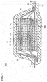
- FIG. 1 is a schematic cross sectional view schematically illustrating a whole structure of a parallel laminated lithium ion secondary battery (hereinafter, also simply referred to as a "parallel laminated type battery"), according to an embodiment of the present invention.
- a parallel laminated type battery 10a of the present embodiment a substantially rectangular power generating element 17 in which a charge-discharge reaction proceeds actually is sealed in a laminate film 22 serving as a battery outer casing material.
- a polymer-metal composite laminate film is used as a battery outer casing material, and the whole periphery thereof is joined by heat fusion. The power generating element 17 is thereby housed and sealed.
- a negative electrode, an electrolyte layer 13, and a positive electrode are laminated.
- negative electrode active material layers 12 are disposed on both sides of a negative electrode current collector 11 (only on one side for the bottom layer and the top layer of the power generating element).
- positive electrode active material layers 15 are disposed on both sides of a positive electrode current collector 14.
- the negative electrode, the electrolyte layer 13, and the positive electrode are laminated in this order such that one negative electrode active material layer 12 faces a positive electrode active material layer 15 adjacent thereto through the electrolyte layer 13.
- the positive electrode active material layer uses a positive electrode active material having a specific composition and structure.
- the negative electrode, the electrolyte layer 13, and the positive electrode adjacent to each other form one unit battery layer 16. Therefore, in the parallel laminated type battery 10 of the present embodiment, a plurality of unit battery layers 16 are laminated, and are thereby electrically connected in parallel.
- a sealing portion (insulating layer) (not illustrated) to insulate the positive electrode current collector 14 from the negative electrode current collector 11 adjacent thereto may be provided.
- the negative electrode active material layer 12 is disposed only on one surface of each of outermost layer negative electrode current collectors 11a positioned in outermost layers of the power generating element 17. By reversing the disposition of the negative electrode and the positive electrode in FIG. 1 , outermost layer positive electrode current collectors may be positioned in outermost layers of the power generating element 17, and the positive electrode active material layer may be disposed only on one surface of each of the outermost layer positive electrode current collectors.
- a negative electrode current collecting plate 18 and a positive electrode current collecting plate 19 conductive with the electrodes are attached to the negative electrode current collector 11 and the positive electrode current collector 14, respectively.
- the negative electrode current collecting plate 18 and the positive electrode current collecting plate 19 are led to the outside of the laminate film 22 so as to be sandwiched between ends of the laminate film 22.
- the negative electrode current collecting plate 18 and the positive electrode current collecting plate 19 may be attached to the negative electrode current collector 11 and the positive electrode current collector 14 of the electrodes by ultrasonic welding, resistance welding, or the like, if necessary through a negative electrode terminal lead 20 and a positive electrode terminal lead 21, respectively ( FIG.1 illustrates this form).
- the negative electrode current collector 11 may be extended to be used as the negative electrode current collecting plate 18, and may be led out from the laminate film 22.
- the positive electrode current collector 14 may be extended to be used as the positive electrode current collecting plate 19, and may be led out from the battery outer casing material 22.
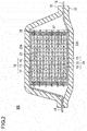
- FIG. 2 is a schematic cross sectional view schematically illustrating a whole structure of a series laminated bipolar lithium ion secondary battery (hereinafter, also simply referred to as a "series laminated type battery”), according to an embodiment of the present invention.
- a series laminated type battery 10b illustrated in FIG. 2 a substantially rectangular power generating element 17 in which a charge-discharge reaction proceeds actually is sealed in a laminate film 22 serving as a battery outer casing material.
- a power generating element 17 of the series laminated type battery 10b contains a plurality of bipolar electrodes 24.
- the bipolar electrode 24 an electrically bonded positive electrode active material layer 15 is formed on one surface of a current collector 23, and an electrically bonded negative electrode active material layer 12 is formed on the other surface of a current collector 23 .
- the positive electrode active material layer uses a positive electrode active material having a specific composition and structure.
- the bipolar electrodes 24 are laminated through electrolyte layers 13 to form the power generating element 17.
- the electrolyte layer 13 holds an electrolyte in the center in a plane direction of a separator as a substrate.
- the bipolar electrode 24 and the electrolyte layer 13 are laminated alternatively such that the positive electrode active material layer 15 of one bipolar electrode 24 faces the negative electrode active material layer 12 of the other bipolar electrode 24 adjacent to the one bipolar electrode 24 through the electrolyte layer 13. That is, the electrolyte layer 13 is sandwiched between the positive electrode active material layer 15 of one bipolar electrode 24 and the negative electrode active material layer 12 of the other bipolar electrode 24 adjacent to the one bipolar electrode 24.
- the positive electrode active material layer 15, the electrolyte layer 13, and the negative electrode active material layer 12 adjacent to each other form one unit battery layer 16. Therefore, in the series laminated type battery 10b of the present embodiment, a plurality of unit battery layers 16 are laminated, and are thereby electrically connected in series. In order to prevent liquid junction due to leakage of an electrolyte solution from the electrolyte layer 13, a sealing portion (insulating part) 25 is disposed in an outer periphery of the unit battery layer 16.
- the positive electrode active material layer 15 is formed only on one surface of an outermost layer current collector 23a on a side of the positive electrode, positioned in an outermost layer of the power generating element 17.
- the negative electrode active material layer 12 is formed only on one surface of an outermost layer current collector 23b on a side of the negative electrode, positioned in an outermost layer of the power generating element 17.
- the positive electrode active material layers 15 may be formed on both surfaces of the outermost layer current collector 23a on the side of the positive electrode.
- the negative electrode active material layers 12 may be formed on both surfaces of the outermost layer current collector 23b on the side of the negative electrode.
- the positive electrode current collecting plate 19 is disposed so as to be adjacent to the outermost layer current collector 23a on the side of the positive electrode.
- the positive electrode current collecting plate 19 is extended and led out from the laminate film 22 serving as a battery outer casing material.
- the negative electrode current collecting plate 18 is disposed so as to be adjacent to the outermost layer current collector 23b on the side of the negative electrode.
- the negative electrode current collecting plate 18 is extended and led out from the laminate film 22 serving as a battery outer casing.
- the insulating part 25 is usually provided around each unit battery layer 16.
- the insulating part 25 is provided in order to prevent contact between the current collectors 23 adjacent to each other in the battery, or to prevent short circuit caused by slightly irregular ends of the unit battery layer 16 in the power generating element 17.
- the number of laminating the unit battery layer 16 is adjusted according to a desired voltage.
- the number of laminating the unit battery layer 16 may be small as long as a sufficient output can be ensured even when the battery is extremely thin. Even in the series laminated type battery 10b, it is necessary to prevent shock from the outside during use and environmental deterioration. Therefore, the power generating element 17 is preferably sealed in the laminate film 22 serving as a battery outer casing material under reduced pressure.
- the positive electrode current collecting plate 19 and the negative electrode current collecting plate 18 are preferably taken out of the laminate film 22.
- the positive electrode active material layer 15 and the positive electrode in FIGS. 1 and 2 include a positive electrode active material having a specific composition and structure described later. This makes it possible to increase the output and the capacity of the non-aqueous electrolyte secondary battery for application to the electric vehicle. In addition, the capacity of the non-aqueous electrolyte secondary battery is not easily lowered even after repeated charge and discharge.
- components of the non-aqueous electrolyte secondary battery will be described in detail.
- the positive electrode generates electric energy through transfer of lithium ions together with the negative electrode.
- the positive electrode essentially contains a current collector and a positive electrode active material layer.
- the positive electrode active material layer is formed on a surface of the current collector.
- the current collector is formed of a conductive material.
- the positive electrode active material layer(s) is/are disposed on one surface or both surfaces thereof.
- a material to form the current collector is not particularly limited.
- a metal or a conductive resin obtained by adding a conductive filler to a conductive polymer material or a non-conductive polymer material can be used.
- the metal examples include aluminum, nickel, iron, stainless steel (SUS), titanium, and copper.
- a clad material of nickel and aluminum, a clad material of copper and aluminum, a plating material of a combination of these metals, or the like can be preferably used.
- a foil obtained by covering a surface of a metal with aluminum may be used.
- aluminum, stainless steel, or copper is preferably used from a viewpoint of conductivity or a battery operating potential.
- Examples of the conductive polymer material include polyaniline, polypyrrole, polythiophene, polyacetylene, polyparaphenylene, polyphenylene vinylene, polyacrylonitrile, and polyoxadiazole. Such a conductive polymer material is advantageous in terms of simplification of a manufacturing process or weight reduction of the current collector because the conductive polymer material has sufficient conductivity without adding a conductive filler.
- non-conductive polymer material examples include polyethylene (PE; high density polyethylene (HDPE), low density polyethylene (LDPE)), polypropylene (PP), polyethylene terephthalate (PET), polyether nitrile (PEN), polyimide (PI), polyamideimide (PAI), polyamide (PA), polytetrafluoroethylene (PTFE), styrene-butadiene rubber (SBR), polyacrylonitrile (PAN), polymethyl acrylate (PMA), polymethyl methacrylate (PMMA), polyvinyl chloride (PVC), polyvinylidene fluoride (PVdF), and polystyrene (PS).
- PE polyethylene
- HDPE high density polyethylene
- LDPE low density polyethylene
- PP polypropylene
- PET polyethylene terephthalate
- PEN polyether nitrile
- PI polyimide
- PAI polyamideimide
- PA polyamide
- PTFE polytetrafluoroethylene
- SBR
- a conductive filler may be added if necessary to the conductive polymer material or the non-conductive polymer material.
- a conductive filler is essentially required in order to impart conductivity to the resin.
- the conductive filler can be used without particular limitation as long as the conductive filler has conductivity.
- Examples of a material having excellent conductivity, potential resistance, or lithium ion blocking include a metal and conductive carbon.
- the metal is not particularly limited, but preferably contains at least one metal selected from the group consisting of Ni, Ti, Al, Cu, Pt, Fe, Cr, Sn, Zn, In, Sb, and K, or an alloy or a metal oxide containing these metals.
- the conductive carbon is not particularly limited, but preferably contains at least one selected from the group consisting of acetylene black, vulcan, black pearl, carbon nanofiber, Ketjen black, carbon nanotube, carbon nanohorn, carbon nanoballoon, and fullerene.
- the addition amount of the conductive filler is not particularly limited as long as sufficient conductivity can be imparted to the current collector. In general, the addition amount is about 5 to 35% by mass.
- the size of the current collector is determined according to use of the battery. For example, a current collector having a large area is used for a large battery requiring a high energy density.
- the thickness of the current collector is not particularly limited, but is usually about 1 to 100 ⁇ m.
- the positive electrode active material layer essentially contains a positive electrode active material having a specific composition and structure.
- the positive electrode active material layer may further contain another positive electrode active material and an additive such as a conductive aid or a binder.
- the positive electrode active material has a composition which can release lithium ions during charge and can absorb lithium ions during discharge.
- the positive electrode active material of the present embodiment contains a solid solution active material represented by the composition formula (1) below.
- z represents the number of oxygen atoms satisfying an atomic valence.
- An alumina cover layer is present on the surface of particles of the solid solution active material. The side of the surface of the solid solution active material in the interface between the solid solution active material particles and the alumina cover layer has a region in which Al element is present (invades).
- a solid solution type positive electrode material (solid solution active material) is studied.
- solid solution active material a layered lithium-containing transition metal oxide made of a solid solution of an electrochemically inactive layered Li 2 MnO 3 and an electrochemically active layered LiMO 2 (here, [M] is a transition metal such as Co, Ni, Mn, or Fe) is studied.
- the phase transition into the spinel phase is caused by oxidation (for example, Mn 3+ ⁇ Mn 4+ ) (irreversible phase transition caused by charge) of a transition metal element (Mn or the like) contained in the transition metal layer in the crystal structure of the positive electrode active material.
- a part of the transition metal element involved in the phase transition does not form the spinel phase (is not fixed), and is eluted outside the crystal structure.
- a part of lattice oxygen is released, and oxygen gas is generated.
- the transition metal element is eluted.
- a charge-discharge cycle around the plateau potential (4.3 to 4.5 V) or by exposure to a potential around the plateau potential for a long time, elution occurs in accordance with the oxidation of the transition metal (Mn or the like) contained in the solid solution active material. Therefore, it is required to stabilize a rock salt layered structure and to suppress the elution of the transition metal such as Mn while the Li 2 MnO 3 composition is electrochemically activated.
- the charge-discharge capacity and the rate characteristics are reduced because an overvoltage (resistance) of the layered Li 2 MnO 3 at the end of charge or at the end of discharge is high with respect to the layered LiMO 2 (for example, LiNi 1/2 Mn 1/2 O 2 or the like).
- Ni or Mn is easily eluted disadvantageously because a use upper limit potential is high (4.3 V or more).
- the solid solution active material in the related art it is necessary to charge the battery to a plateau potential or more (for example, 4.4 to 4.8 V) for activation (accompanied by change of a part of the crystal structure to a spinel phase structure (phase transition)).
- the partial phase transition into the spinel phase (LiMnO 2 system) is caused by a process of oxidation (for example, Mn 3+ ⁇ Mn 4+ ; irreversible phase transition caused by charge) of a transition metal element (Mn, Ni, or the like) contained in the transition metal layer and a process of release of lattice oxygen in accordance with the above process in the crystal structure of the positive electrode active material.
- the elution of the transition metal (Mn, Ni, or the like) contained in the solid solution active material occurs in accordance with the oxidation of the transition metal.
- the elution of the transition metal in accordance with the change of the crystal structure on the surface layer lowers durability.
- the positive electrode active material a solid solution active material including an alumina layer coated (covered) with Al 2 O 3 on the surface thereof is used.
- an amount of the transition metal (Mn) eluted outside the crystal structure without forming the spinel phase (without being fixed) is reduced when Mn in the transition metal layer moves to the Li layer and a part thereof performs a phase transition into the spinel phase in accordance with the activation. Performance and durability can be improved.
- a covalent bond with oxygen is strengthened by invasion (by obtaining a region of presence) of a part of Al element in the Al 2 O 3 coat (cover) layer into the surface layer of the active material particles. Therefore, release of lattice oxygen in accordance with oxidation of other transition metals occurs less. Therefore, a generation amount of oxygen gas is reduced, and a generation amount of an oxygen defect in the crystal structure is also reduced. Furthermore, even by repetition of the charge-discharge cycle around the plateau potential (4.3 to 4.5 V), or by exposure to a potential around the plateau potential for a long time, the crystal structure is stabilized and release of oxygen occurs less.
- the most unstable surface layer (to 20 nm or 30 nm; FIGS. 16(a) and 16(b) and Example 5) of the active material particles is stabilized by the Al 2 O 3 coat and invasion of Al element. Therefore, performance and durability can be improved more than the Al 2 O 3 coat technique as in Patent Literature 3 , in which invasion (presence) of Al element in the surface layer of the active material particles is difficult.
- Al element in the Al 2 O 3 coat layer does not invade the particles (bulk) or replace the particles. Therefore, insertion and release of Li in accordance with oxidation-reduction of Ni or Mn in the bulk are not hindered. Therefore, it is possible to obtain a high capacity.
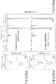
- FIG. 3 is a diagram comparing discharge curves at the time of output characteristic test of electrodes (positive electrodes).
- output characteristic tests of batteries using two kinds of electrodes were performed under the same condition.
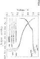
- FIG. 4 is a diagram comparing charge-discharge curves of the electrodes (positive electrodes) at high temperature (50°C).
- the charge-discharge tests of batteries using four kinds of electrodes (positive electrodes) were performed under the same condition.
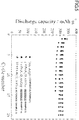
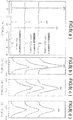
- FIG. 5 is a diagram comparing cycle characteristics of the electrodes (positive electrodes) at high temperature (50°C).
- the charge-discharge cycle tests of batteries using four kinds of electrodes (positive electrodes) were performed under the same condition.
- a compound represented by the composition formula of Reference Example 1: Li 1.5 [Ni 0.40 Mn 0.60 Co 0.40 [Li] 0.1 ]O z was used.
- a laminate type battery of Comparative Example 1 was used for the battery using the positive electrode using the positive electrode active material not covered with alumina as the positive electrode active material.
- a laminate type battery of Reference Example 3 was used for the battery using the positive electrode using the positive electrode active material obtained by providing the 5% by mass alumina layer on the surface of the solid solution active material.
- a laminate type battery.of Reference Example 4 was used.
- a laminate type battery of Reference Example 5 was used for the battery using the positive electrode using the positive electrode active material obtained by providing the 10% by mass alumina layer on the surface of the solid solution active material.
- the initial charge treatment, the gas removing treatment 1, the activation treatment, the gas removing treatment 2, and the performance evaluation were performed as an evaluation of battery characteristics of Reference Example 1, and then the life time evaluation was performed in a similar manner to Reference Example 1 to obtain the cycle characteristics.
- the battery performance (capacity, rate characteristics, and cycle characteristics) can be improved.
- the elution of the transition metal it is possible to suppress a reaction between the surface layer of the solid solution active material (particles) and the electrolyte solution, and to suppress reduction in the average voltage after the cycles.
- a shift is preferably present in each of (003), (101), and (104) which are layered rock salt structure peaks.
- (003) is preferably shifted to a lower angle side
- (101) is preferably shifted to a higher angle side
- (104) is preferably shifted to a higher angle side, with respect to a layered rock salt structure peak in the X-ray diffraction only of the solid solution active material.
- a width of each peak shift is preferably (003): -0.08° ⁇ ⁇ ⁇ 0.00°, (101) : 0.00° ⁇ ⁇ ⁇ 0.05°, (104) : 0.00° ⁇ ⁇ ⁇ 0.05°, with respect to the layered rock salt structure peak in the X-ray diffraction only of the solid solution active material.
- LiMO 2 indicates a layered rock salt structure (rock salt type layered structure) as an XRD (X-ray diffraction) peak.
- Li 2 MnO 3 indicates a superlattice diffraction peak at 20-23°, but the other peaks indicate the same layered rock salt structure (rock salt type layered structure) as LiMO 2 . Therefore, the solid solution active material of Li 2 MnO 3 and LiMO 2 indicates a layered rock salt structure (rock salt type layered structure) having a superlattice diffraction peak at 20-23°.
- the solid solution active material when a solid solution state of the transition metal such as Mn is insufficient, LiMnO 2 is present as impurities from an initial stage, or a part of the crystal structure changes after an activation treatment at a high potential of the plateau potential or more (for example, 4.4 to 4.8 V). Furthermore, by repetition of the charge-discharge cycle (for example, 4.3 to 4.5 V), a part of the crystal structure changes, and LiMnO 2 which is present as impurities or has been generated in accordance with the change in a part of the crystal structure gradually changes to the spinel phase after the cycles. An XRD diffraction peak characteristic of the spinel phase comes to appear.
- the surface of which is coated (covered) with Al 2 O 3 inorganic substance such as Al 2 O 3
- Al 2 O 3 organic substance such as Al 2 O 3
- an amount of the transition metal (Mn) eluted outside the crystal structure without forming the spinel phase (without being fixed) is reduced when Mn in the transition metal layer moves to the Li layer and a part thereof performs a phase transition into the spinel phase in accordance with the activation. Performance and durability can be improved.
- a covalent bond with oxygen is strengthened by having shifts in the layered rock salt structure peaks (003), (101), and (104) in the X-ray diffraction of the positive electrode active material (by invasion of a part of Al element in the Al 2 O 3 coat (cover) layer into the surface layer of the active material particles).
- Al element in the Al 2 O 3 coat layer does not invade the particles (bulk) or replace the particles. Therefore, insertion and release of Li in accordance with oxidation-reduction of Ni or Mn in the bulk are not hindered. Therefore, it is possible to obtain a high capacity.
- the present reference embodiment in order to confirm that the side of the surface of the solid solution active material in the interface between the solid solution active material particles and the alumina layer has a region in which Al element is present, presence of Al element on the surface layer of the active material particles can be confirmed qualitatively using a high-resolution measuring device.
- the analysis device analysis method
- the analysis device include XPS (X-ray photoelectron spectroscopy), TEM-EDX (transmission electron microscope-energy dispersive X-ray spectroscopy), STEM-EDX/EELS (scanning transmission electron microscope-energy dispersive X-ray spectroscopy/electron energy loss spectroscope), and HAADF-STEM (high-angle scattering dark field-scanning transmission electron microscope image).
- XPS X-ray photoelectron spectroscopy
- TEM-EDX transmission electron microscope-energy dispersive X-ray spectroscopy
- STEM-EDX/EELS scanning transmission electron microscope-energy dispersive X-ray
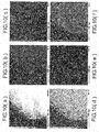
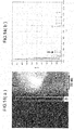
- FIG. 6 (a) is a diagram illustrating a vicinity of an interface between an Al 2 O 3 layer and a solid solution active material (particles), forming the positive electrode active material particles of the present reference embodiment, observed using an electron microscope (SEM).
- FIG. 6 (b) is a diagram illustrating the interface between the Al 2 O 3 layer and the solid solution active material (particles), forming the positive electrode active material particles of the present reference embodiment, observed using an XPS.
- FIG. 6(a) a sample (2 wt% Al 2 O 3 coated sample) obtained by providing a 2% by mass alumina layer on the surface of the solid solution active material, which was a positive electrode active material made in Reference Example 3, was used.
- argon etching was performed from the surface of the alumina layer (thickness 10 nm; refer to Reference Example 3 in Table 1) to the depth of 15 to 20 nm in the depth direction. It is thereby possible to obtain elemental distribution on the surface layer (depth direction; 5 to 10 nm) on the side of the active material of the interface between the Al 2 O 3 layer and the solid solution active material (particles).
- a compound represented by the composition formula of Reference Example 1: Li 1.5 [Ni 0.40 Mn 0.60 Co 0.40 [Li] 0.1 ]O z was used.
- the Al 2 O 3 layer formed on the surface of the solid solution active material particles (a dense part on the left in the diagram, having a dark color) can be confirmed in a region sandwiched between the two lines.
- the part of the Al 2 O 3 layer is formed by bonding of Al 2 O 3 particles and is layered. Therefore, the part of the Al 2 O 3 layer can be visually recognized as a granular part having relatively dark and light parts.
- FIG. 6(a) the Al 2 O 3 layer formed on the surface of the solid solution active material particles (a dense part on the left in the diagram, having a dark color) can be confirmed in a region sandwiched between the two lines.
- the part of the Al 2 O 3 layer is formed by bonding of Al 2 O 3 particles and is layered. Therefore, the part of the Al 2 O 3 layer can be visually recognized as a granular part having relatively dark and light parts.
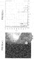
- FIG. 7(A) is a chart illustrating an XRD (X-ray diffraction) pattern of the positive electrode active material in which a composition formula of the solid solution active material has been identified by elemental analysis.
- XRD X-ray diffraction
- FIG. 7(A) a chart illustrating an XRD (X-ray diffraction) pattern of a sample (bare sample) using a solid solution active material not covered with alumina as a positive electrode active material, is illustrated in the lower diagram.
- a compound represented by the composition formula of Reference Example 1: Li 1.5 [Ni 0.40 Mn 0.60 Co 0.40 [Li] 0.1 ]O z was used.
- the positive electrode active material made in Comparative Example 1 was used for the sample (bare sample) using the solid solution active material not covered with alumina as the positive electrode active material.
- FIG. 7(B) is a diagram illustrating enlarged peaks shown in (a) of the two patterns (upper and lower diagrams) in FIG. 7(A).
- FIG. 7(C) is a diagram illustrating enlarged peaks shown in (b) of the two patterns (upper and lower diagrams) in FIG. 7(A) .
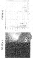
- FIG. 8(a) is a chart illustrating an XRD (X-ray diffraction) pattern of the positive electrode active material in which a composition formula of the solid solution active material has been identified by elemental analysis.
- XRD X-ray diffraction
- FIG. 8(a) a chart illustrating an XRD (X-ray diffraction) pattern of a sample (bare sample) using a solid solution active material not covered with alumina as a positive electrode active material, is illustrated in the lower diagram.
- FIG. 8(b) is a diagram illustrating enlarged layered rock salt structure peaks (003) of the three patterns (upper, middle, and lower diagrams) in FIG. 8(a) such that the peak shifts and shift widths thereof can be determined.
- FIG. 8(c) is a diagram illustrating enlarged layered rock salt structure peaks (101) of the three patterns (upper, middle, and lower diagrams) in FIG. 8(a) such that the peak shifts and shift widths thereof can be determined.
- FIG. 8(d) is a diagram illustrating enlarged layered rock salt structure peaks (104) of the three patterns (upper, middle, and lower diagrams) in FIG. 8(a) such that the peak shifts and shift widths thereof can be determined.
- the XRD (X-ray diffraction) illustrated in FIGS. 8(a) to 8(d) was measured by powder X-ray diffraction using Rigaku, Ultima III and CuK ⁇ as a radiation source.
- FIG. 8(a) a peak was observed in each of the layered rock salt structure peaks (003), (101), and (104).
- FIGS. 8(b) to 8(d) a peak shift was slightly observed in each of the layered rock salt structure peaks (003), (101), and (104) in the sample obtained by providing an alumina layer in each of the middle and upper diagrams with respect to the sample (bare sample) of the solid solution active material in the lower diagram. This indicates that the Al 2 O 3 layer on the surface of the solid solution active material is not only for covering.
- FIG. 8(b) it can be observed in FIG. 8(b) that (003) is shifted to a lower angle side, in FIG.
- FIG. 9(a) is a diagram illustrating a BF (Bright field)-STEM Image (bright field-scanning transmission electron microscope image) of the active material particles.
- FIG. 9(b) is a diagram illustrating a HAADF-STEM Image (high-angle scattering dark field-scanning transmission electron microscope image) of the active material particles in the same field as FIG. 9(a) .
- the positive electrode active material particles (secondary particles) of Reference Example 3 made by coating the surface of the solid solution active material (particles) having a size of the active material particle (secondary particle) of about 2 ⁇ m with 2% by mass alumina, were used.
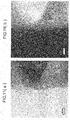
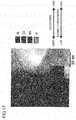
- FIGS. 10(a) to 10(f) are diagrams illustrating quantitative mapping data by STEM-EDX (scanning transmission electron microscope-energy dispersive X-ray spectroscopy).
- FIG. 10(a) illustrates the same HAADF-STEM image as FIG. 9(b) .
- FIG. 10(b) illustrates mapping data of O (on the upper middle) measured in the same field as HAADF-STEM ( FIG. 10(a) on the upper left).
- FIG. 10(a) illustrates mapping data of O (on the upper middle) measured in the same field as HAADF-STEM ( FIG. 10(a) on the upper left).
- FIG. 10(c) illustrates mapping data of Al (on the upper right) measured in the same field as HAADF-STEM ( FIG. 10(a) on the upper left).
- FIG. 10(d) illustrates mapping data of Mn (on the lower left) measured in the same field as HAADF-STEM ( FIG. 10(a) on the upper left).
- FIG. 10(e) illustrates mapping data of Co (in the lower middle) measured in the same field as HAADF-STEM ( FIG. 10(a) on the upper left).
- FIG. 10(f) illustrates mapping data of Ni (on the lower right) measured in the same field as HAADF-STEM ( FIG. 10(a) on the upper left).
- observation of the STEM image contains two types of observation methods of a bright-field (BF) STEM image and a dark-field (DF) STEM image.
- the bright-field (BF) STEM image images using an electron beam passing through the sample.
- the dark-field (DF) STEM image images using an electron beam scattered from the sample.
- BF-STEM image illustrated in FIG. 9 (a) a transmission image showing an inner structure of the sample can be observed as in a normal TEM image.
- (HAA) DF-STEM image illustrated in FIG. 9 (b) a composition image from which a contrast reflecting the composition of the sample can be obtained can be observed.
- the HAADF high-angle scattering annular dark field
- a contrast of elastically scattered electrons due to atomic number (Z) is superior. Therefore, the HAADF is an imaging method also referred to as a Z-contrast image.
- a substance having a large atomic number is seen brightly (refer to FIG. 9 (b) , FIG. 11 (b) , and FIGS. 12 to 17 ).
- the HAADF-STEM high-angle scattering annular dark field scanning transmission electron microscopy
- an image is obtained by irradiating a sample with a narrow electron beam during an operation and by detecting transmission electrons scattered at a high angle with an annular detector.
- a material having a higher Z 2 ⁇ is scattered at a higher angle.
- a heavy element is dark in the STEM image, and bright in the HAADF-STEM image.
- a contrast proportional to an atomic weight (Z) is obtained. Therefore, the image is also referred to as the Z contrast image.
- the STEM-EDX quantitative mapping information of composition distribution of a sample can be obtained by taking a characteristic X-ray generated at each point into an EDS (Energy-Dispersive-Spectroscopy) detector while the sample is scanned with a narrow electron beam.
- EDS Electronicgy-Dispersive-Spectroscopy
- FIG.11 (a) is a diagram illustrating a BF (Bright field)-STEM Image (bright field-scanning transmission electron microscope image) of the active material particles.
- FIG. 11(b) is a diagram illustrating a HAADF-STEM Image (high-angle scattering dark field-scanning transmission electron microscope image) of the active material particles in the same field as FIG. 11(a) .
- FIG. 12 illustrates the same HAADF-STEM image as FIG. 11(b) .
- regions (four parts enclosed by rectangular frames) in which presence (invasion) of Al element is observed by elemental analysis are divided by the circled numbers 1 to 4.
- FIG. 13(a) illustrates the same HAADF-STEM image as FIG. 12 .
- FIG. 13(b) is a diagram obtained by elemental analysis of the part to be observed in elemental distribution in FIG. 13(a) .
- FIG. 13(b) in the part of the circled number 1 in FIG. 13(a) to be observed in elemental distribution, Al element is hardly observed.
- the thickness of the alumina layer is about 10 to 20 nm. The part to be observed is outside the alumina layer.
- FIG. 14(a) illustrates the same HAADF-STEM image as FIG. 12 .
- the rectangular frame of a part to be observed in elemental distribution (part of the circled number 2 in the image) is illustrated by a bold line.
- FIG. 14(b) is a diagram obtained by elemental analysis of the part to be observed in elemental distribution in FIG. 14(a) .
- the alumina layer is made of a light element having a smaller atomic number than the solid solution active material, and is positioned in the dark part.
- the thickness of the alumina layer is about 10 to 20 nm. This indicates that the part to be observed is the alumina layer.
- FIG. 15(a) illustrates the same HAADF-STEM image as FIG. 12 .
- the rectangular frame of a part to be observed in elemental distribution (part of the circled number 3 in the image) is illustrated by a bold line.
- FIG. 15(b) is a diagram obtained by elemental analysis of the part to be observed in elemental distribution in FIG. 15(a) .
- the part of the circled number 3 in the HAADF-STEM image in FIG. 15(a) is a region from the interface between the active material and the alumina layer to the outermost layer of the solid solution active material particles (5 to 10 nm). The observation of Al element in this region indicates presence (invasion) of Al element from the interface between the active material and the alumina layer into the side of the active material.
- FIG. 16(a) illustrates the same HAADF-STEM image as FIG. 12 .
- the rectangular frame of a part to be observed in elemental distribution (part of the circled number 4 in the image) is illustrated by a bold line.
- FIG. 16(b) is a diagram obtained by elemental analysis of the part to be observed in elemental distribution in FIG. 16(a) .
- FIG. 17 is a diagram illustrating concentration distribution of Ni, Co, Mn, and Al with color tones based on the observation results of FIGS. 13 to 16 in the same HAADF-STEM image as FIG. 12 .
- the part of the circled number 4 in FIG. 16(a) is a region from the interface between the active material and the alumina layer to the bottom of the outermost layer of the solid solution active material particles (10 to 20 nm).
- Al element also in this region indicates presence (invasion) of Al element from the interface between the active material and the alumina layer into the surface layer (to about 20 nm) on the side of the active material.
- the Al concentration is decreased than in the outermost layer of the active material. Therefore, it is considered that such a concentration gradient that the Al concentration is highest in the outermost layer due to the invasion of Al element as illustrated in FIG. 17 , and is gradually decreased toward the inside, is formed. From the observation results of FIG. 6a , FIGS. 10(a) to 10(f) , and FIGS. 13(a) to 16(b) , as illustrated in FIG.
- the alumina (Al 2 O 3 ) coat layer is distributed on the surface of the solid solution active material particles (refer to FIG. 6a and FIGS. 10(a) to 10(f) ).
- Al element invades (is present in) the inside to the depth of about 10 to 20 nm from the surface of the solid solution active material particles. The invasion depth depends on the thickness (coating amount) of the alumina layer. However, it is understood that the Al element can invade (be present in) the inside to the depth of about 30 nm (refer to Example 19 in Table 1).
- the positive electrode active material of the present embodiment contains a solid solution active material represented by the composition formula (1) : Li 1.5 [Ni a Mn b Co c [Li] d [X] e ]O z .
- z represents the number of oxygen atoms satisfying an atomic valence.
- LiMO 2 indicates a rock salt type layered structure as an X-ray diffraction (XRD) peak.
- Li 2 MnO 3 indicates a superlattice diffraction peak at 20-23°, but the other peaks indicate the same rock salt type layered structure as LiMO 2 . Therefore, the solid solution system of Li 2 MnO 3 and LiMO 2 indicates a rock salt type layered structure having a superlattice diffraction peak at 20-23°. That is, the positive electrode active material of the composition formula (1) has a plurality of specific diffraction peaks in the X-ray diffraction (XRD) measurement.
- XRD X-ray diffraction
- the positive electrode active material of the above-described composition formula is a solid solution system of Li 2 MnO 3 and LiMnO 2 .
- the diffraction peak at 20-23° is a superlattice diffraction peak characteristic of Li 2 MnO 3 .
- diffraction peaks at 36.5-37.5° (101), 44-45° (104), and 64-65 (108) /65-66 (110) are characteristic of the rock salt type layered structure of LiMnO 2 .
- the diffraction peak indicating the rock salt type layered structure contains the diffraction peaks at (003), (101), and (104) (refer to bare sample in FIG. 8(a) ).
- the solid solution active material of the present embodiment does not include a peak other than the diffraction peak indicating the rock salt type layered structure, for example, other peaks derived from impurities, in the angle range. Existence of these other peaks indicates that the solid solution active material contains a structure other than the rock salt type layered structure.
- the cycle characteristics can be surely improved in the present embodiment.
- the solid solution active material represented by the composition formula (1) of the present embodiment at least one selected from Ti, Zr, and Nb is introduced to a solid solution by replacing Mn 4+ in the transition metal layer including Ni, Co, and Mn to form the rock salt type layered structure. That is, the valence.e of X in the general formula (1) is larger than 0. That is, the solid solution active material contain s at least one selected from Ti, Zr and Nb, corresponding to X in the general formula (1) (refer to Examples 14 to 19).
- an amount of the transition metal (Mn or the like) eluted outside the crystal structure without forming the spinel phase (without being fixed) is reduced when Mn in the transition metal layer moves to the Li layer and a part thereof performs a phase transition into the spinel phase in accordance with the activation. Performance and durability can be improved. Furthermore, a covalent bond between oxygen and the replacement element is strengthened. Therefore, release of lattice oxygen in accordance with oxidation of other transition metals occurs less. Therefore, a generation amount of oxygen gas is reduced, and a generation amount of an oxygen defect in the crystal structure is also reduced.
- Performance and durability can be improved: Furthermore, a covalent bond with oxygen is strengthened by invasion of a part of Al element in the Al 2 O 3 coat (cover) layer into the surface layer of the active material particles. Therefore, release of lattice oxygen in accordance with oxidation of other transition metals occurs less. Therefore, a generation amount of oxygen gas is reduced, and a generation amount of an oxygen defect in the crystal structure is also reduced. A most unstable surface layer (to 35 nm) of the active material particles is stabilized by the Al 2 O 3 coat and invasion of Al element. Therefore, performance and durability can be improved more than the Al 2 O 3 coat technique in the related art, in which invasion (presence) of Al element in the surface layer of the active material particles is difficult.
- Al element in the Al 2 O 3 coat layer does not invade the particles (bulk) or replace the particles. Therefore, insertion and release of Li in accordance with oxidation-reduction of Ni or Mn in the bulk are not hindered. Therefore, it is possible to obtain a high capacity.
- the diffraction peak indicating the rock salt type layered structure of the solid solution active material is preferably shifted to a lower angle side. That is, the solid solution active material of the composition formula (1) above, including at least one selected from Ti, Zr and Nb, preferably has diffraction peaks at 20-23°, 35.5-36.5° (101), 43.5-44.5° (104) , and 64-65° (108) /65-66° (110) in the X-ray diffraction (XRD) measurement.
- XRD X-ray diffraction
- the shift of the diffraction peak to a lower angle side indicates formation of a solid solution containing a larger amount of Ti or the like in the solid solution active material of the composition formula (1) above and replacement of Mn with Ti or the like. It is considered that Mn is prevented from being eluted more largely.
- the covalent bond between oxygen and the replacement element is strengthened by formation of a solid solution containing Ti or the like by replacement of Mn 4+ with Ti or the like in the transition metal layer of the solid solution active material of the composition formula (1) above. It is possible to make the release of oxygen in the crystal lattice in accordance with oxidation of the transition metal occur less. This can suppress the generation of oxygen gas, and can reduce a generation amount of an oxygen defect in the crystal structure.
- a + b + c + e satisfies 1.1 ⁇ [a + b + c + e] ⁇ 1.4.
- nickel (Ni), cobalt (Co), and manganese (Mn) contribute to a capacity and output characteristics from viewpoints of improving purity of the material and improving electron conductivity.
- Ti or the like partially replaces Mn in the crystal lattice. It is possible to optimize the elements and further improve the capacity and the output characteristics by satisfying 1.1 ⁇ [a + b + c + e] ⁇ 1.2. Therefore, when a positive electrode active material satisfying this relationship is used for a lithium ion secondary battery, it is possible to maintain a high capacity and exhibit an excellent initial charge-discharge efficiency by maintaining a high reversible capacity.
- a satisfies preferably 0 ⁇ a ⁇ 1.5, more preferably 0.1 ⁇ a ⁇ 0.75.
- the positive electrode active material contains nickel in the above-described range of d with the proviso that the valence of nickel (Ni) is two. Therefore, the crystal structure may not be stabilized.
- the crystal structure of the positive electrode active material easily becomes a rock salt type layered structure.
- b satisfies preferably 0 ⁇ b ⁇ 1.5, more preferably 0.2 ⁇ b ⁇ 0.9.
- the positive electrode active material contains manganese in the above-described range of d with the proviso that the valence of manganese is four, and further contains nickel (Ni). Therefore, the crystal structure may not be stabilized.
- the crystal structure of the positive electrode active material easily becomes a rock salt type layered structure.
- c preferably satisfies 0 ⁇ c ⁇ 1.5.
- the positive electrode active material contains nickel and manganese in the above-described range of d with the proviso that the valence of cobalt is three.
- the positive electrode active material further contains cobalt (Co) in the above range of d with the proviso that the valence of nickel (Ni) is two and the valence of manganese (Mn) is four. Therefore, the crystal structure of the positive electrode active material may not be stabilized.
- c satisfies c ⁇ 0.6 the crystal structure of the positive electrode active material easily becomes a rock salt type layered structure.
- 0.1 ⁇ d ⁇ 0.4 When d does not satisfy 0.1 ⁇ d ⁇ 0.4, the crystal structure of the positive electrode active material may not be stabilized. On the contrary, when d satisfies 0.1 ⁇ d ⁇ 0.4, the positive electrode active material easily becomes a rock salt type layered structure.
- the range of d is more preferably 0.15 ⁇ d ⁇ 0.35.
- d When d is 0.1 or more, the composition does not easily become close to Li 2 MnO 3 , and charge and discharge are performed easily. Therefore, d of 0.1 or more is preferable.
- composition formula (1) 0 ⁇ e ⁇ 0.5.
- at least one selected from Ti, Zr and Nb is contained, if 0.01 ⁇ e ⁇ 0.5, at least one selected from Ti, Zr and Nb can replace Mn 4+ sufficiently such that the elution of Mn 4+ is suppressed.
- e satisfies preferably 0.02 ⁇ e ⁇ 0.5, more preferably 0.05 ⁇ e ⁇ 0.3.
- the ionic radius of Mn 4+ is 0. 54 ⁇ .
- the ionic radii of Ti 4+ , Zr 4+ , and Nb 5+ are 0.61 ⁇ , 0.72 ⁇ , and 0.64 ⁇ , respectively.
- Each of Ti, Zr, and Nb is larger than Mn. Therefore, as Mn 4+ in the positive electrode active material is replaced with Ti or the like, the crystal lattice expands, and the diffraction peak indicating the rock salt type layered structure is shifted to a lower angle side. On the contrary, when the diffraction peak is shifted to a lower angle side, the replacement amount of Mn 4+ with Ti or the like is larger, and the crystal structure is stabilized easily. That is, the elution of Mn at the time of charge and discharge is suppressed more. It is possible to prevent reduction in the capacity of the secondary battery more effectively.
- the specific surface area of the solid solution active material is preferably 0.2 to 0. 6 m 2 /g, more preferably 0.25 to 0.5 m 2 /g.
- the specific surface area is 0.2 m 2 /g or more, it is possible to obtain a sufficient output of the battery. Therefore, the specific surface area of 0.2m 2 /g or more is preferable.
- the specific surface area is 0.6 m 2 /g or less, it is possible to suppress the elution of manganese more. Therefore, the specific surface area of 0.6 m 2 /g or less is preferable.
- values of the specific, surface area values measured using a measurement device BELSORP-mini II manufactured by Bel Japan, Inc. were used.
- the average particle diameter of the solid solution active material (secondary particles) is preferably 10 to 20 ⁇ m, more preferably of 12 to 18 ⁇ m.
- the average particle diameter is 10 ⁇ m or more, it is possible to suppress the elution of manganese. Therefore, the average particle diameter of 10 ⁇ m or more is preferable.
- the average particle diameter is 20 ⁇ m or less, it is possible to cover every part of the surface of the primary particles forming the secondary particles with alumina in the coating of alumina during manufacturing the positive electrode active material. In addition, it is possible to suppress foil break, clogging, or the like in the coating step onto a current collector during manufacturing the positive electrode. Therefore, the average particle diameter of 20 ⁇ m or less is preferable.
- the average particle diameter values measured using a particle size distribution measuring device of a laser diffraction scattering method are used. The average particle diameter can be measured, for example, using a particle size distribution analyzer (model LA-920) manufactured by Horiba, Ltd.
- the positive electrode active material of the present embodiment contains the solid solution active material of the composition formula (1) above, (a) an alumina cover layer on the surface of the solid solution active material, and (b) a region in which Al element is present on the side of the surface of the solid solution active material in the interface between the solid solution active material and the alumina cover layer.
- Alumina layer (alumina coat layer, alumina cover layer, Al 2 O 3 layer, or the like)
- an alumina layer is present on the surface of the solid solution active material (particles) of the composition formula (1) above.
- the alumina layer covers 50% or more, preferably 60% or more, more preferably 70% or more, still more preferably 80% or more, particularly preferably 90% or more, of the surface of the .solid solution active material particles. Above all, the alumina layer desirably covers the entire surface thereof (about 100%: approximately 97 to 98%). A part where the solid solution active material is exposed does not remain thereby. Therefore, it is possible to further enhance the above-described effects.
- the present embodiment it has been found that 50% or more of the surface of the solid solution active material particles, or the entire surface thereof (about 100%: approximately 97 to 98%) can be covered by preparing the positive electrode active material in a manufacturing method and conditions different from the existing manufacturing methods in a method for manufacturing the positive electrode active material described later (refer to FIG. 6 (a) ). For details, it has been found that 50% or more of the surface of the solid solution active material particles, or the entire surface thereof (about 100%: approximately 97 to 98%) can be covered and Al element easily invades the surface layer of the solid solution active material, by optimizing pH and calcination temperature using aluminum nitrate as a raw material source.
- the new problem can be also solved by obtaining ⁇ -Al 2 O 3 (calcination temperature 400 to 450°C) as a crystal structure formed from Al(OH) 3 by preparing the positive electrode active material in a manufacturing method and conditions different from the existing manufacturing methods (particularly by optimizing the calcination temperature) in the method for manufacturing the positive electrode active material described later.
- an embodiment in which the alumina layer covers a part (less than 50%) of the surface of the solid solution active material particles is included in the technical scope of the present embodiment as long as the embodiment can exhibit the effects of the present embodiment effectively.
- the average thickness of the alumina layer is 1 to 60 nm, preferably 2 to 55 nm, more preferably 3 to 30 nm, still more preferably 3 to 20 nm, particularly preferably 5 to 15 nm.
- release of lattice oxygen in accordance with oxidation of the transition metal occurs less.
- a generation amount of oxygen gas is thereby reduced, and a generation amount of an oxygen defect in the crystal structure is also reduced.
- the elution of the transition metal (Mn, Ni, or the like) contained in the solid solution active material in accordance with oxidation of the transition metal is suppressed, and release of oxygen occurs less. Therefore, performance and durability are improved.
- the average thickness of the Al 2 O 3 layer disposed on the surface of the solid solution active material particles is 1 nm or more, particularly 3 or more, durability is sufficiently improved by the Al 2 O 3 coat layer.
- the average thickness of the Al 2 O 3 layer is 60 nm or less, particularly 20 nm or less, Li ions easily move and performance is improved sufficiently.
- the average thickness of the alumina layer can be measured, for example, using an observation image of SEM or TEM.
- the average particle diameter of the solid solution active material and the average particle diameter of the positive electrode active material having the alumina layer may be measured using a particle size distribution measuring device of a laser diffraction scattering method, and a difference therebetween may be used as the average thickness of the alumina layer.
- a content of alumina is 1 to 5% by mass, with respect to the total amount of the positive electrode active material.
- the content of alumina is within the above-described range, release of lattice oxygen in accordance with oxidation of the transition metal occurs less.
- a generation amount of oxygen gas is thereby reduced, and a generation amount of an oxygen defect in the crystal structure is also reduced.
- the elution of the transition metal (Mn, Ni, or the like) contained in the solid solution active material in accordance with oxidation of the transition metal is suppressed, and release of oxygen occurs less. Therefore, performance and durability are improved.
- alumina Al 2 O 3
- Li ions easily move and performance is improved sufficiently.
- the content of alumina (Al 2 O 3 ) can be measured by an elemental analysis method such as ICP, EDX, or EPMA.
- the solid solution active material of the composition formula (1) above and a region in which Al element is present on the side of the surface of the solid solution active material in the interface between the solid solution active material and the alumina cover layer coated on the surface thereof are contained.
- the above-described improvement effects are increased by provision of the Al 2 O 3 cover layer on the surface layer of the solid solution active material particles and invasion (presence) of Al element in the surface layer of the solid solution active material particles.
- Al element is preferably present in a region inside the solid solution active material of the composition formula (1) above from the surface of the active material to a thickness (invasion depth) of 35 nm, preferably from the surface to 30 nm, more preferably from the surface to 25 nm.
- a thickness (invasion depth) of 35 nm preferably from the surface to 30 nm, more preferably from the surface to 25 nm.
- the maximum depth (maximum distance from the surface) at which Al element invades (is present in) the surface of the solid solution active material of the composition formula (1) above is 1 nm or more and 35 nm or less, preferably 3 nm or more and 30 nm or less, more preferably 5 nm or more and 25 nm or less.
- the maximum depth (maximum distance from the surface) at which Al element invades (is present in) the surface of the solid solution active material of the composition formula (1) above is 1 nm or more, preferably 3 nm or more, performance can be improved sufficiently by the Al 2 O 3 coat layer.
- the maximum depth (maximum distance from the surface) at which Al element invades (is present in) the surface of the solid solution active material of the composition formula (1) above is 35 nm or less, preferably 30 nm or less, durability is sufficiently improved without destabilizing the crystal structure in the surface layer of the solid solution active material. Furthermore, Li ions easily move and performance is improved sufficiently.
- the invasion depth of Al element into the surface layer of the solid solution active material can be measured using XPS (X-ray photoelectron spectroscopy), TEM-EDX (transmission electron microscope-energy dispersive X-ray spectroscopy), STEM-EDX/EELS (scanning transmission electron microscope-energy dispersive X-ray spectroscopy/electron energy loss spectroscope), HAADF-STEM (high-angle scattering dark field-scanning transmission electron microscope image), or the like.
- XPS X-ray photoelectron spectroscopy
- TEM-EDX transmission electron microscope-energy dispersive X-ray spectroscopy
- STEM-EDX/EELS scanning transmission electron microscope-energy dispersive X-ray spectroscopy/electron energy loss spectroscope
- HAADF-STEM high-angle scattering dark field-scanning transmission electron microscope image
- the specific surface area of the positive electrode active material of the present embodiment is preferably 0.2 to 0.6 m 2 /g, more preferably of 0.25 to 0.5 m 2 /g.
- the specific surface area is 0.2 m 2 /g or more, it is possible to obtain a sufficient output of the battery. Therefore, the specific surface area of 0.2 m 2 /g or more is preferable.
- the specific surface area is 0.6 m 2 /g or less, it is possible to suppress the elution of manganese more. Therefore, the specific surface area of 0.6 m 2 /g or less is preferable.
- the average particle diameter of the positive electrode active material of the present embodiment is preferably 10 to 20 ⁇ m, more preferably of 12 to 18 ⁇ m.
- the average particle diameter is 10 ⁇ m or more, it is possible to suppress the elution of manganese. Therefore, the average particle diameter of 10 ⁇ m or more is preferable.
- the average particle diameter is 20 ⁇ m or less, it is possible to suppress foil break, clogging, or the like in the coating step onto a current collector during manufacturing the positive electrode. Therefore, the average particle diameter of 20 ⁇ m or less is preferable.
- values measured using a particle size distribution measuring device of a laser diffraction scattering method are used. The average particle diameter can be measured, for example, using a particle size distribution analyzer (model LA-920) manufactured by Horiba, Ltd.
- the positive electrode active material can be prepared by the following method.
- the method preferably further includes a step of preparing the solid solution active material.
- the step is characterized by containing a first step of mixing an organic acid salt of a transition metal having a melting point of 100°C to 350°C; a second step of melting the mixture obtained in the first step at 100°C to 350°C; a third step of subjecting the molten substance obtained in the second step to pyrolysis at a temperature equal to higher than the melting point; and a fourth step of calcining the pyrolysate obtained in the third step.
- a citrate of at least one of Ti, Zr and Nb is further mixed.
- an organic acid salt of an alkali metal is further mixed.
- the step of coating the surface of the solid solution active material with alumina further includes a fifth step of mixing the solid solution active material and an aluminum nitrate solution at pH of 7 to 8; a sixth step of drying the solid solution active material precursor obtained in the fifth step; and a seventh step of calcining the dry solid solution active material precursor obtained in the sixth step at a temperature of 450°C ⁇ 50°C.
- the preparation of the solid solution active material of the composition formula (1) above includes a first step of mixing a citrate of at least one of Ti, Zr and Nb to be added, and an organic acid salt of a transition metal having a melting point of 100°C to 350°C; a second step of melting the mixture obtained in the first step at 100°C to 350°C; a third step of subjecting the molten substance obtained in the second step to pyrolysis at a temperature equal to or higher than the melting point; and a fourth step of calcining the pyrolysate obtained in the third step.
- the preparation of the positive electrode active material (coating the surface of the solid solution active material with Al 2 O 3 ) includes a step of mixing the solid solution active material obtained in the above-described "preparation of the solid solution active material of the composition formula (1)" with an aluminum nitrate solution at pH of 7 to 8, drying the solid solution active material precursor obtained, and calcining the solid solution active material precursor at a temperature of 450°C ⁇ 50°C.
- each step will be described.
- a citrate of at least one of Ti, Zr and Nb is mixed with an organic acid salt of a transition metal having a melting point of 100°C to 350°C.
- the citrate of at least one of Ti, Zr, and Nb is preferably mixed in a form of a citric acid complex aqueous solution.
- the citric acid complex aqueous solution of at least one of Ti, Zr, and Nb is not limited to the following solutions, but can be preferably prepared as follows.
- anhydrous citric acid is dissolved in an organic solvent such as acetone.
- An alkoxide of at least one of Ti, Zr, and Nb is added to the solution.
- the citric acid complex aqueous solution finally has a concentration of 1 to 10% by mass in terms of an oxide of at least one of Ti, Zr, and Nb.
- the aqueous solution is allowed to stand for one day.
- the precipitate is filtered to obtain a citric acid complex aqueous solution of at least one of Ti, Zr, and Nb as a filtrate.
- Examples of the alkoxide of at least one of Ti, Zr, and Nb include titanium tetraisopropoxide, zirconium tetraisopropoxide, niobium isopropoxide, titanium ethoxide, titanium n-propoxide, titanium butoxide, zirconium ethoxide, zirconium n-propoxide, zirconium butoxide, niobium ethoxide, and niobium butoxide.
- an organic acid salt of a transition metal having a melting point of 100°C to 350°C is added to the resulting citric acid complex aqueous solution of at least one of Ti, Zr and Nb to obtain a mixture.
- the organic acid salt of a transition metal having a melting point of 100°C to 350°C include nickel acetate, manganese acetate, cobalt acetate, and manganese citrate.
- An organic acid salt of an alkali metal is preferably further mixed with the citric acid complex aqueous solution of at least one of Ti, Zr, and Nb.
- Preferable examples of the organic acid salt of an alkali metal include lithium acetate and lithium citrate. Mixing the organic acid salt of an alkali metal at this stage is preferable due to a simple manufacturing method.
- the mixture obtained in the first step is melted at 100°C to 350°C, preferably 200 to 300°C.
- the heated molten substance (slurry) obtained in the second step is subjected to pyrolysis at a temperature equal to or higher than the melting point of the organic acid salt of a transition metal used in the first step to obtain a pyrolysate as a dry powder.
- pyrolysis is performed at the highest melting point or higher.
- the molten substance can be heated and sprayed at 200 to 600°C, more preferably 200 to 400°C using a spray device.
- the pyrolysate obtained in the third step is calcined at 600 to 1200°C, more preferably 800 to 1100°C for 5 to 20 hours, preferably 10 to 15 hours.
- temporary calcination may be performed.
- the temporary calcination can be performed at 200 to 700°C, more preferably 300 to 600°C for 1 to 10 hours, more preferably 2 to 6 hours. In this way, the solid solution active material of the composition formula (1) of the present embodiment is obtained.
- the step of preparation of the positive electrode active material includes a fifth step of mixing the solid solution active material obtained in the above-described "preparation of the solid solution active material of the composition formula (1)" with an aluminum nitrate solution at pH of 7 to 8; a sixth step of drying the solid solution active material precursor obtained in the fifth step; and a seventh step of calcining the dry solid solution active material precursor obtained in the sixth step at a temperature of 450°C ⁇ 50°C.
- the Al 2 O 3 layer formed in a part or the whole (50 to 100%) of the surface of the solid solution active material particles through these steps preferably has high mobility of Li ions, and preferably suppresses the elution of the transition metal highly.
- the solid solution active material in which the Al 2 O 3 layer is present in a part or the whole (50 to 100%) of the surface of the solid solution active material particles and Al element has invaded the surface layer of the solid solution active material particles (that is, the positive electrode active material of the present embodiment).
- a battery having excellent performance and durability can be provided.
- each step will be described.
- the solid solution active material obtained in the fourth step is mixed with an aluminum nitrate solution at pH of 7 to 8.
- the solid solution active material precursor can be thereby obtained.
- aluminum nitrate As a raw material of aluminum, aluminum nitrate is preferable. This is because a nitrate ion can be decomposed and removed in the calcination step (seventh step) and a battery using the positive electrode active material has thereby excellent performance. When aluminum sulfate or aluminum chloride is used, a sulfate ion or a chloride ion remains. A battery using the positive electrode active material has lower performance. Aluminum acetate is not suitable for the present method (precipitation reaction).
- a precipitant is further used.
- ammonium water is preferable. This is because an ammonium ion can be decomposed and removed in the calcination step (seventh step) and a battery using the positive electrode active material has thereby excellent performance.
- sodium hydroxide is used, Na remains as impurities of the positive electrode active material. A battery using the positive electrode active material has lower performance.
- the mixing temperature and mixing time are not particularly limited as long as the reaction between aluminum nitrate and ammonium water is performed sufficiently and a desired solid solution active material precursor (the solid solution active material on the surface of which aluminum hydroxide is precipitated) is formed by the mixing operation.
- the mixing temperature solution temperature of the reaction system
- the mixing time can be 30 minutes to 3 hours.
- the resulting solid solution active material precursor may be soaked in the solution for about 3 hours or less. This forms a preferable coat of an alumina layer. Charge-discharge characteristics and cycle durability are improved.
- a mixing method is not particularly limited.
- a mixing and stirring method known in the art can be used.
- the solid solution active material precursor obtained in the fifth step is dried.
- the solid solution active material precursor is filtered from the mixed solution of the fifth step.
- a filtering method (device) is not particularly limited.
- a filtering method (device) known in the related art can be used.
- the filtered solid solution active material precursor is dried. Drying conditions are not particularly limited as long as the solid solution active material precursor can be dried sufficiently. That is, when the steps from drying to calcination are performed continuously, the drying step (sixth step) may not be distinguished from the calcination step (seventh step) strictly. This is because the steps from drying to calcination may be performed at predetermined calcination temperature. From the above, as the drying conditions, the drying temperature can be 80 to 200°C, and the drying time can be 30 minutes to 12 hours, preferably 1 to 6 hours. An atmosphere during drying is not particularly limited. Drying can be performed in the air atmosphere or the like.
- a drying method (device) is not particularly limited.
- a drying method (device) known in the art can be used. Specifically, for example, it is possible to use vacuum drying, hot air drying, infrared (IR) drying, and natural drying appropriately in combination thereof.
- IR infrared
- the solid solution active material precursor obtained in the sixth step is calcined at a temperature of 450°C ⁇ 50°C.
- the calcination conditions of the solid solution active material precursor by performing the calcination at calcination temperature of 450°C ⁇ 50°, preferably 420°C to 480°C, for 1 to 12 hours, preferably 2 to 6 hours, it is possible to manufacture the solid solution active material in which the Al 2 O 3 layer is present in a part or the whole (50 to 100%) of the surface of the solid solution active material particles and A1 element has invaded the surface layer of the solid solution active material particles (that is, the positive electrode active material of the present embodiment).
- the calcination temperature is lower than 400°C, decomposition of aluminum hydroxide is not sufficient, a desired Al 2 O 3 coat layer cannot be formed, and a battery using the positive electrode active material has poor durability.
- calcination temperature when the calcination temperature is higher than 500°C, the Al 2 O 3 layer becomes dense, mobility of Li ions is lowered, and a battery using the positive electrode active material has poor performance.
- An atmosphere during calcination is not particularly limited. Calcination can be performed in the air atmosphere or the like.
- a calcination method (device) is not particularly limited.
- a calcination method (device) known in the art can be used.
- the positive electrode active material of the present embodiment and the method for manufacturing the same have been described hereinabove.
- components (conductive aid, binder, or the like) of the positive electrode, other than the positive electrode active material, and components (negative electrode, electrolyte layer, outer casing material, or the like) of a battery using the positive electrode, other than the positive electrode, will be described.
- the conductive aid means an additive blended in order to enhance conductivity of the active material layer.
- the positive electrode active material layer contains a conductive material, an electron network inside the positive electrode active material layer is formed effectively, and the output characteristics of a battery can be improved.
- the conductive aid is not particularly limited.
- examples thereof include carbon powder such as acetylene black, carbon black, channel black, thermal black, Ketjen black, or graphite, various carbon fibers such as a vapor grown carbon fiber (VGCF; registered trademark), and expanded graphite.
- carbon powder such as acetylene black, carbon black, channel black, thermal black, Ketjen black, or graphite
- various carbon fibers such as a vapor grown carbon fiber (VGCF; registered trademark), and expanded graphite.
- VGCF vapor grown carbon fiber
- the content of the conductive aid with respect to the total amount of the positive electrode active material layer is normally 0 to 30% by mass, preferably 1 to 10% by mass, more preferably 3 to 7% by mass.
- the binder is added in order to bind the components in the active material layer or to bind the active material layer to the current collector so as to maintain the electrode structure.
- the binder is not particularly limited. However, examples thereof include polyvinylidene fluoride (PVdF), carboxymethylcellulose (CMC), polytetrafluoroethylene (PTFE), polyvinyl acetate, an acrylic resin, polyimide, an epoxy resin, a polyurethane resin, a urea resin, and a synthetic rubber-based binder such as styrene-butadiene rubber (SBR).
- PVdF polyvinylidene fluoride
- CMC carboxymethylcellulose
- PTFE polytetrafluoroethylene
- SBR synthetic rubber-based binder
- the content of the binder with respect to the total amount of the positive electrode active material layer is normally 0 to 50% by mass, preferably 5 to 45% by mass, more preferably 10 to 25% by mass, particularly preferably 15 to 20% by mass.
- the negative electrode generates electric energy through transfer of lithium ions together with the positive electrode.
- the negative electrode essentially contains a current collector and a negative electrode active material layer.
- the negative electrode active material layer is formed on a surface of the current collector.
- the current collector which can be used for the negative electrode is similar to the current collector which can be used for the positive electrode. Therefore, description thereof will be omitted here.
- the negative electrode active material layer contains a negative electrode active material.
- the negative electrode active material layer may further contain an additive such as a conductive aid or a binder.
- the negative electrode active material has a composition which can release lithium ions during discharge and absorb lithium ions during charge.
- the negative electrode active material is not particularly limited as long as the negative electrode active material can absorb or release lithium reversibly.
- preferable examples thereof include a metal such as Si or Sn, a metal oxide such as TiO, Ti 2 O 3 , TiO 2 , SiO 2 , SiO, or SnO 2 , a composite oxide of lithium and a transition metal such as Li 4/3 Ti 5/3 O 4 or Li 7 MnN, a Li-Pb based alloy, a Li-Al based alloy, Li, a carbon material such as carbon powder, natural graphite, artificial graphite, carbon black, activated carbon, carbon fiber, coke, soft carbon, or hard carbon.
- the negative electrode active materials may be each used alone, or may be used in a form of a mixture of two or more kinds thereof.
- the element to form an alloy with lithium is not limited to the following elements. However, specific examples thereof include Si, Ge, Sn, Pb, Al, In, Zn, H, Ca, Sr, Ba, Ru, Rh, Ir, Pd, Pt, Ag, Au, Cd, Hg, Ga, Tl, C, N, Sb, Bi, O, S, Se, Te, and Cl.
- a negative electrode active material containing a carbon material and/or at least one element selected from the group consisting of Si, Ge, Sn, Pb, Al, In, and Zn is preferable.
- a negative electrode active material containing a carbon material, Si, or Sn is more preferable.
- a carbon material is particularly preferably used.
- carbonaceous particles having a low discharge potential with respect to lithium is preferable.
- examples thereof include natural graphite, artificial graphite, a blend of natural graphite and artificial graphite, a material obtained by coating natural graphite with amorphous carbon, soft carbon, and hard carbon.
- the shape of the carbonaceous particle is not particularly limited, and may be massive, spherical, fibrous, or the like. However, preferably, the shape is not scaly. The shape is preferably spherical or massive. A carbonaceous particle not having a scaly shape is preferable from viewpoints of performance and durability.
- the carbonaceous particle the carbonaceous particle the surface of which is covered with amorphous carbon is preferable.
- the whole surface of the carbonaceous particle is more preferably covered with the amorphous carbon.
- only a part thereof may be covered.
- a method for covering the surface of graphite particles with amorphous carbon is not particularly limited. An example thereof is a wet method.
- carbonaceous particles (powder) serving as a core are dispersed in and mixed with a mixed solution in which amorphous carbon is dissolved or dispersed in a solvent, and then the solvent is removed.
- a mixed solution in which amorphous carbon is dissolved or dispersed in a solvent
- Other examples thereof include a dry method and a gas phase method such as a CVD method.
- a dry method solid carbonaceous particles are mixed with solid amorphous carbon, and a mechanical energy is added to the resulting mixture so that the carbonaceous particles are covered with the amorphous carbon. It is possible to confirm by laser spectroscopy or the like that the carbonaceous particles are covered with the amorphous carbon.
- a BET specific surface area of the negative electrode active material is preferably 0.8 to 1.5 m 2 /g. When the specific surface area is within the above range, cycle characteristics of a non-aqueous electrolyte secondary battery can be improved.
- a tap density of the negative electrode active material is preferably 0.9 to 1.2 g/cm 3 . The tap density within the above range is preferable from a viewpoint of an energy density.
- the surface of the negative electrode active material is covered with an amorphous carbon layer, the negative electrode active material is made of a graphite material not having a scaly shape, the negative electrode material has a BET specific surface area of 0.8 to 1.5 m 2 /g and a tap density of 0.9 to 1.2 g/cm 3 .
- the negative electrode active material has a BET specific surface area of 0.8 to 1.5 m 2 /g and a tap density of 0.9 to 1.2 g/cm 3 .
- the average particle diameter of the negative electrode active material is not particularly limited, but is preferably 1 to 100 ⁇ m, more preferably 1 to 20 ⁇ m from viewpoints of increase in capacity, reactivity, and cycle durability of the negative electrode active material.
- the conductive aid which can be used for the negative electrode is similar to the conductive aid which can be used for the positive electrode. Therefore, description thereof will be omitted here.
- the binder which can be used for the negative electrode is similar to the binder which can be used for the positive electrode. Therefore, description thereof will be omitted here.
- the electrolyte layer functions as a spacial partition wall (spacer) between the positive electrode and the negative electrode.
- the electrolyte layer also holds an electrolyte which is a moving medium of lithium ions between the positive and negative electrodes during charge and discharge.
- the electrolyte forming the electrolyte layer is not particularly limited. It is possible to appropriately use a liquid electrolyte and a polymer electrolyte such as a polymer gel electrolyte or a polymer solid electrolyte. In the present embodiment, the liquid electrolyte is preferable.
- a lithium salt is dissolved in an organic solvent.
- the organic solvent include at least one of dimethyl carbonate (DMC), diethyl carbonate (DEC), dipropyl carbonate (DPC), methylpropyl carbonate (MPC), ethylpropyl carbonate (EPC), methyl ethyl carbonate (MEC), ethylene carbonate (EC), propylene carbonate (PC), butylene carbonate (BC), fluorine-containing cyclic carbonate (such as fluoroethylene carbonate (FEC)), fluorine-containing chain carbonate, fluorine-containing chain ether, and fluorine-containing chain ester.
- DMC dimethyl carbonate
- DEC diethyl carbonate
- DPC dipropyl carbonate
- MPC methylpropyl carbonate
- EPC ethylpropyl carbonate
- MEC methyl ethyl carbonate
- EC ethylene carbonate
- PC propylene carbonate
- BC butylene carbonate
- the lithium salt it is preferable to use at least LiPF 6 .
- LiN(SO 2 C 2 F 5 ) 2 , LiN(SO 2 CF 3 ) 2 , LiBF 4 , LiClO 4 , LiAsF 6 , LiSO 3 CF 3 , or the like can be used.
- the concentration of the lithium salt is preferably 0.1 to 5 mol/L, more preferably 0.1 to 2 mol/L.
- the liquid electrolyte it is preferable to contain as an additive at least one selected among organic sulfone compounds, organic disulfone compounds, vinylene carbonate derivatives, ethylene carbonate derivatives, ester derivatives, dihydric phenol derivatives, terphenyl derivatives, phosphate derivatives, and lithium fluorophosphate derivatives.
- organic sulfone compounds organic disulfone compounds
- vinylene carbonate derivatives vinylene carbonate derivatives
- ethylene carbonate derivatives ester derivatives
- dihydric phenol derivatives terphenyl derivatives
- phosphate derivatives lithium fluorophosphate derivatives
- lithium fluorophosphate derivatives such as lithium monofluorophosphate or lithium difluorophosphate are more preferable.
- examples of the organic sulfone compounds include 1,3-propane sultone (saturated sultone) and 1,3-propene sultone (unsaturated sultone); examples of the organic disulfone compounds (disultone derivatives, cyclic disulfonate) include methylene methane disulfonate; examples of the vinylene carbonate derivatives include vinylene carbonate (VC); examples of the ethylene carbonate derivatives include fluoroethylene carbonate (FEC); examples of the ester derivatives include 4-biphenylyl acetate, 4-biphenylyl benzoate, 4-biphenylyl benzyl carboxylate, and 2-biphenylyl propionate; examples of the dihydric phenol derivatives include 1,4-diphenoxy benzene and 1,3-dip
- the additive is contained in the electrolyte solution preferably at 0.1 to 5% by mass, more preferably at 0.5 to 3.5% by mass.
- the polymer electrolyte is classified into the gel electrolyte containing an electrolyte solution and the polymer solid electrolyte not containing an electrolyte solution.
- the above-described liquid electrolyte is injected into a matrix polymer having lithium ion conductivity.
- the matrix polymer having lithium ion conductivity include polyethylene oxide (PEO), polypropylene oxide (PPO), and a copolymer thereof.
- An electrolyte salt such as a lithium salt can be dissolved well in such a matrix polymer.
- a separator may be used in the electrolyte layer.
- a specific form of the separator is, for example, a microporous film made of a polyolefin such as polyethylene or polypropylene, a hydrocarbon such as polyvinylidenefluoride-hexafluoropropylene (PVdF-HFP), glassfiber, or the like.
- the polymer solid electrolyte In the polymer solid electrolyte, a lithium salt is dissolved in the above-described matrix polymer.
- the polymer solid electrolyte does not contain an organic solvent. Therefore, when the electrolyte layer is formed by the polymer solid electrolyte, there is no risk of liquid leakage from a battery, and reliability of the battery can be improved.
- the matrix polymer of the polymer gel electrolyte or the polymer solid electrolyte can exhibit excellent mechanical strength by forming a crosslinked structure.
- a polymerizable polymer for forming a polymer electrolyte for example, PEO or PPO
- a polymerization treatment such as thermal polymerization, ultraviolet polymerization, radiation polymerization, or electron beam polymerization.
- the above-described electrolyte may be contained in an active material layer of an electrode.
- a current collecting plate (tab) electrically connected to the current collector is taken out of the laminate film serving as an outer casing material.
- a material for forming the current collecting plate is not particularly limited, and a known highly conductive material conventionally used for a current collecting plate for a lithium ion secondary battery can be used.
- the material for forming the current collecting plate include a metal material such as aluminum, copper, titanium, nickel, stainless steel (SUS), or an alloy thereof. From viewpoints of light weightiness, corrosion resistance, and high conductivity, aluminum and copper are more preferable, and aluminum is particularly preferable.
- the same material or different materials can be used for the positive electrode current collecting plate (positive electrode tab) and the negative electrode current collecting plate (negative electrode tab).
- a sealing portion is a member specific to a series laminated type battery, and prevents leakage of an electrolyte layer.
- the sealing portion can prevent contact between current collectors adjacent to each other in the battery, or can prevent short circuit caused by slightly irregular ends of the laminated electrodes.
- a material for forming the sealing portion is not particularly limited.
- examples thereof include a polyolefin resin such as polyethylene or polypropylene, an epoxy resin, rubber, and polyimide.
- the polyolefin resin is preferably used from viewpoints of corrosion resistance, chemical resistance, a film forming property, economical efficiency, and the like.
- a lead used in a known laminated type secondary battery can be used as a material of a negative electrode terminal lead and a positive electrode terminal lead.
- a portion taken out from a battery outer casing material is preferably covered with a heat resistant and insulating heat-shrinkable tube or the like so that the part has no influence on a product (for example, an automobile component, in particular, an electronic device or the like) according to electric leak due to contact with neighboring instruments, wiring, or the like.
- the outer casing material a metal can case conventionally known can be used.
- the laminate film 22 illustrated in FIG. 1 may be used as an outer casing material to pack the power generating element 17.
- the laminate film can have a three-layer structure formed by laminating polypropylene, aluminum, and nylon in this order. By using such a laminate film, it is possible to open the outer casing material, add a capacity recovering material, and reseal the outer casing material easily.
- a method for manufacturing a non-aqueous electrolyte secondary battery is not particularly limited.
- the non-aqueous electrolyte secondary battery can be manufactured by a known method. Specifically, the method includes (1) manufacturing an electrode, (2) manufacturing a unit battery layer, (3) manufacturing a power generating element, and (4) manufacturing a laminated type battery.
- the method for manufacturing a non-aqueous electrolyte secondary battery will be described using an example, but is not limited thereto.
- An electrode (positive electrodes or negative electrode) can be manufactured, for example, by preparing an active material slurry (positive electrode active material slurry or negative electrode active material slurry), coating a current collector with the active material slurry, and drying and then pressing the active material slurry.
- the active material slurry contains the above-described active material (positive electrode active material or negative electrode active material) and a solvent.
- the active material slurry may further contain a conductive aid and a binder.
- the positive electrode active material slurry essentially contains the above-described positive electrode active material having a specific composition and structure. Therefore, the present embodiment also provides a positive electrode.
- the solvent is not particularly limited. Examples thereof include N-methyl-2-pyrrolidone (NMP), dimethylformamide, dimethylacetamide, methylformamide, cyclohexane, hexane, and water.
- NMP N-methyl-2-pyrrolidone
- dimethylformamide dimethylacetamide
- methylformamide dimethylformamide
- cyclohexane cyclohexane
- hexane cyclohexane
- water water
- a method for coating the current collector with the active material slurry is not particularly limited. Examples thereof include a screen printing method, a spray coating method, an electrostatic spray coating method, an inkjet method, and a doctor blade method.
- a method for drying the coating film formed on the surface of the current collector is not particularly limited as long as at least a part of the solvent in the coating film is removed. Examples thereof include heating. Drying conditions (drying time, drying temperature, or the like) can be appropriately set in accordance with a volatilization rate of a solvent contained in a utilized active material slurry, a coating amount of the active material slurry, or the like. A part of the solvent may remain. The remaining solvent can be removed in a pressing step described later, or the like.
- a pressing method is not particularly limited. Examples thereof include calender roll and flat plate press.
- a unit battery layer can be manufactured by laminating the electrodes (positive electrode and negative electrode) manufactured in (1) through the electrolyte layer.
- a power generating element can be manufactured by laminating the unit battery layers while an output and a capacity of the unit battery layer, an output and a capacity required for a battery, and the like are taken into account appropriately.
- a current collector, an insulating plate, or the like as a component is not particularly limited, and can be selected according to the above-described shape.
- a laminated type battery is preferable.
- a lead is bonded to the current collector of the power generating element obtained above, and the positive electrode lead or the negative electrode lead is bonded to a positive electrode tab or a negative electrode tab.
- the power generating element is then put into the laminate sheet such that the positive electrode tab and the negative electrode tab are exposed to the outside of the battery.
- An electrolyte solution is injected thereinto using an injector and vacuum sealed.
- the laminated type battery can be thereby manufactured.
- thermocompression bonding in the above (4) manufacturing laminated type battery, at the time of sealing, three sides of the laminate sheet (outer casing material) are completely sealed (regularly sealed) by thermocompression bonding into a rectangular shape, and the remaining one side is temporarily sealed by thermocompression bonding.
- the remaining one side for example, may be freely opened or closed by clipping or the like.
- thermocompression bonding When the side is temporarily sealed by thermocompression bonding, the side can be unsealed by applying a slight pressure. After degassing, the side may be temporarily sealed again by thermocompression bonding. Finally, the side can be completely sealed (regularly sealed) by thermocompression bonding.
- thermocompression bonding As an initial (first) gas removing treatment, the following treatment is performed. First, the one side temporarily sealed by thermocompression bonding is unsealed. Gas is removed at 10 ⁇ 3 hPa for five minutes. Thereafter, the one side is subjected to thermocompression bonding again to perform temporary sealing. In addition, pressure molding (contact pressure: 0.5 ⁇ 0.1 MPa) is performed using a roller to make the electrode adhere to the separator sufficiently.
- the following electrochemical pretreatment method is performed.
- the activation treatment method an electrochemical pretreatment method where the constant current charging method is used and the voltage is used as a stop condition has been described as an example.
- a constant current constant voltage charging method may be used.
- a charge amount or time may be used as the stop condition.
- thermocompression bonding As an initial (first) gas removing treatment, the following treatment is performed. First, the one side temporarily sealed by thermocompression bonding is unsealed. Gas is removed at 10 ⁇ 3 hPa for five minutes. Thereafter, the one side is subjected to thermocompression bonding again to perform regular sealing. In addition, pressure molding (contact pressure: 0.5 ⁇ 0.1 MPa) is performed using a roller to make the electrode adhere to the separator sufficiently.
- the solid solution active materials had the same composition and Al 2 O 3 amounts were different from one another.
- the dry powder was pulverized with a mortar, and then subjected to temporary calcination at 500°C for 5 hours.
- This powder was subjected to temporary calcination at 500°C for 2 hours. Thereafter, the powder was subjected to calcination at 900°C for 12 hours to obtain solid solution active material C1.
- composition of solid solution active material C1 obtained in this way is as follows.
- Positive electrode active material C1 obtained in this way was powder in which the surface of the particles of solid solution active material C1 obtained in the above "Preparation of solid solution active material C1" was coated with 0.5% by mass of Al 2 O 3 with respect to the total amount of positive electrode active material C1.
- the average particle diameter of obtained positive electrode active material C1 was 8 ⁇ m.
- the average particle diameters of positive electrode active materials C2 to 20 obtained in other Reference Examples 2 to 13, Examples 14 to 19 and Comparative Example 1 were the same as that of Reference Example 1.
- the crystal structure and crystallinity of obtained positive electrode active material C1 were evaluated by X-ray diffraction.
- a Cu-K ⁇ ray was used for an X-ray source. The measurement was performed under the conditions of tube voltage 40 KV, tube current 20 mA, scanning speed 2°/min, divergence slit width 0.5°, and light receiving slit width 0.15° (refer to FIGS. 8(a) to (d) ).
- the slurry for a positive electrode had the following composition.
- Positive electrode active material positive electrode active material C1 obtained above 9.2 parts by weight
- the slurry for a positive electrode having the above-described composition was prepared as follows. First, 2.0 parts by weight of a 20% binder solution in which a binder was dissolved in a solvent (NMP) and 4.0 parts by weight of the solvent (NMP) were added to a 50 ml disposable cup. The resulting mixture was stirred with a stirring deaerator (rotating and revolving mixer: Awatori Rentaro AR-100) for one minute to manufacture a binder diluted solution. Subsequently, 0.4 parts by weight of a conductive aid, 9.2 parts by weight of positive electrode active material C1, and 2.6 parts by weight of the solvent (NMP) were added to this binder diluted solution. The resulting mixture was stirred for 3 minutes using the stirring deaerator to obtain a slurry for a positive electrode (solid concentration: 55% by weight).
- the above sheet-like positive electrode was subjected to compression molding by applying a roller press, and cut to manufacture positive electrode C1 having a weight of one surface of the positive electrode active material layer of about 11.0 mg/cm 2 and a density of 2.65 g/cm 3 .
- positive electrode C1 was dried in a vacuum drying furnace. Positive electrode C1 was disposed in the drying furnace, and then the pressure was reduced (100 mmHg (1.33 ⁇ 10 4 Pa)) at room temperature (25°C) to remove the air in the drying furnace. Subsequently, the temperature was raised to 120°C at 10°C/min while nitrogen gas was circulated (100 cm 3 /min), and the pressure was reduced again at 120°C. Positive electrode C1 was allowed to stand for 12 hours while nitrogen in the furnace was discharged, and then the temperature was lowered to room temperature. Positive electrode C1 from the surface of which water had been removed was obtained in this way.
- the slurry for a negative electrode had the following composition.
- Negative electrode active material natural graphite 9.4 parts by weight
- the slurry for a negative electrode having the above-described composition was prepared as follows. First, 5 parts by weight of (NMP) was added to 2.5 parts by weight of a 20% binder solution in which a binder was dissolved in the solvent (NMP). The resulting mixture was stirred with a stirring deaerator for one minute to manufacture a binder diluted solution. To this binder diluted solution, 0.1 parts by weight of a conductive aid, 9.4 parts by weight of negative electrode active material powder, and 3.0 parts by weight of the solvent (NMP) were added. The resulting mixture was stirred for 3 minutes using the stirring deaerator to obtain a slurry for a negative electrode (solid concentration: 50% by weight).
- the specific surface area was 1.05 m 2 /g (measurement device: BELSORP-mini II manufactured by Bel Japan), and the tap density was 1.1 g/cm 3 (measurement device: tap density measurement device manufactured by Nippon Rufuto Co., Ltd.).
- the average particle diameter of the obtained negative electrode active material was 24 ⁇ m.
- electrolytic copper current collecting foil having a thickness of 10 ⁇ m was coated with the slurry for a negative electrode using an automatic coating device. Subsequently, this current collecting foil coated with the slurry for a negative electrode was dried using a hot plate (100°C to 110°C, drying time: 30 minutes) to form a sheet-like negative electrode having a remaining NMP amount of 0.02% by weight or less in the negative electrode active material layer.
- the obtained sheet-like negative electrode was subjected to compression molding by applying a roller press, and cut to manufacture negative electrode A1 having a weight of one surface of the negative electrode active material layer of about 9.50 mg/cm 2 and a density of 1.45 g/cm 3 .
- a roller press When the surface of negative electrode A1 was observed, generation of crack was not observed.
- negative electrode A1 manufactured by the above procedure was dried in a vacuum drying furnace. Negative electrode A1 was disposed in the drying furnace, and then the pressure was reduced (100 mmHg (1.33 ⁇ 10 4 Pa)) at room temperature (25°C) to remove the air in the drying furnace. Subsequently, the temperature was raised to 135°C at 10°C/min while nitrogen gas was circulated (100 cm 3 /min), and the pressure was reduced again at 135°C. Negative electrode A1 was allowed to stand for 12 hours while nitrogen in the furnace was discharged, and then the temperature was lowered to room temperature. Negative electrode A1 from the surface of which water had been removed was obtained in this way.
- Positive electrode C1 obtained above was cut so as to have an active material layer area of length 2.5 cm ⁇ width 2.0 cm. Uncoated surfaces (surfaces of aluminum current collecting foil, not coated with slurry) of these two pieces were stuck to each other such that the current collectors thereof face each other, and the current collecting foil part was subjected to spot welding. A positive electrode having active material layers formed on both surfaces of the two-layered current collecting foil integrated by spot welding in the outer periphery thereof, was thereby formed. Thereafter, a positive electrode tab (positive electrode current collecting plate) of aluminum was welded to the current collecting foil part to form positive electrode C11. That is, positive electrode C11 has the active material layers formed on both surfaces of the current collecting foil.
- Negative electrode A1 obtained above was cut so as to have an active material layer area of length 2.7 cm ⁇ width 2.2 cm. Thereafter, a negative electrode tab of electrolytic copper was welded to the current collecting foil part to form negative electrode A11. That is, negative electrode A11 has the active material layer formed on one surface of the current collecting foil.
- a five-layered laminated type power generating element was manufactured by sandwiching a separator (S) made of porous polypropylene (length 3. 0 cm ⁇ width 2.5 cm, thickness 25 ⁇ m, porosity 55%) between these negative electrode A11 and positive electrode C11 to which tabs had been welded.
- the laminated type power generating element had a structure of negative electrode (one surface)/separator/positive electrode (both surfaces)/separator/negative electrode (one surface), that is, a structure in which A11, (S), C11, (S), and A11 were laminated in this order. Subsequently, both sides thereof were sandwiched by a laminate film made of aluminum (length 3.5 cm ⁇ width 3.5 cm).
- thermocompression bonding Three sides thereof were sealed by thermocompression bonding to house the power generating element.
- 0.4 cm 3 /cell the above five layered structure has a two-cell structure and an injection amount per cell was 0.4 cm 3
- an electrolyte solution was injected into this power generating element.
- the remaining one side was temporarily sealed by thermocompression bonding to manufacture a laminate type battery.
- the laminate type battery was allowed to stand at 25°C for 24 hours while a contact pressure of 0.5 Mpa was applied.
- LiPF 6 electrolyte
- EC ethylene carbonate
- DEC diethyl carbonate
- LiPO 2 F 2 lithium difluorophosphate
- the power generating element was set to an evaluate cell attachment jig, and a positive electrode lead and a negative electrode lead were each attached to a tab end of the power generating element. A test was performed.
- the laminate type battery manufactured in Reference Example 1 was subjected to an initial charge treatment and an activation treatment under the following conditions to evaluate performance thereof.
- An aging treatment of the battery was performed as follows. Charging was performed at 25°C at 0.05 C for 4 hours (SOC: about 20%) by a constant current charging method. Subsequently, the battery was charged at 25°C at 0.1 C rate to 4.45 V. Thereafter, charging was stopped, and the battery was allowed to stand in the state (SOC: about 70%) about for two days (48 hours).
- thermocompression bonding The one side temporarily sealed by thermocompression bonding was unsealed. Gas was removed at 10 ⁇ 3 hPa for five minutes. Thereafter, the one side was subjected to thermocompression bonding again to perform temporary sealing. In addition, pressure molding (contact pressure 0.5 ⁇ 0.1 MPa) was performed using a roller to make the electrode adhere to the separator sufficiently.
- thermocompression bonding The one side temporarily sealed by thermocompression bonding was unsealed. Gas was removed at 10 ⁇ 3 hPa for five minutes. Thereafter, the one side was subjected to thermocompression bonding again to perform regular sealing. In addition, pressure molding (contact pressure: 0.5 ⁇ 0.1 MPa) was performed using a roller to make the electrode adhere to the separator sufficiently.
- Battery evaluation was performed as follows. That is, the battery was charged by a constant current constant voltage charging method in which the battery was charged at 0.1 C rate until the maximum voltage became 4.5 V, and then the battery was allowed to stand about for 1 hour to 1.5 hours. The battery was discharged by a constant current discharge method in which the battery was discharged at 0.1 C rate until the battery minimum voltage became 2.0 V. Any test was performed at room temperature. At this time, a discharge capacity at 0.1 C rate was referred to as "0.1 C discharge capacity (mAh/g)", and was compared with those in other Examples and Reference and Comparative Examples. Results are shown in Table 1.
- a ratio of the discharge capacity at the 200-th cycle with respect to the discharge capacity at the first cycle was referred to as "capacity retention rate (%)", and was compared with those in other Examples and Reference and Comparative Examples. Results are shown in Table 1.
- positive electrodes C2 to C5 of Reference Examples 2 to 5 were manufactured using positive electrode active materials C2, C3, C4, and C5 obtained by coating solid solution active material C1 obtained in Reference Example 1 with 1% by mass, 2% by mass, 5% by mass, and 10% by mass of Al 2 O 3 , respectively, according to Reference Example 1. Thereafter, laminate type batteries of Reference Examples 2 to 5 were manufactured according to Reference Example 1 to evaluate battery characteristics. Obtained results are shown in Table 1.
- composition of solid solution active material C6 obtained in this way was as follows.
- composition of solid solution active material C7 obtained in this way was as follows.
- the solid solution active materials had the same composition (system not containing Co) and Al 2 O 3 amounts were different from one another.
- composition of solid solution active material C8 obtained in this way was as follows.
- positive electrodes C9 to C11 of Reference Examples 9 to 11 were manufactured using positive electrode active materials C9 to C11 obtained by coating solid solution active material C8 obtained in Reference Example 8 with 1% by mass, 2% by mass, and 5% by mass of Al 2 O 3 , respectively, according to Reference Example 8. Thereafter, laminate type batteries of Reference Examples 9 to 11 were manufactured according to Reference Example 8 to evaluate battery characteristics. Obtained results are shown in Table 1.
- composition of solid solution active material C12 obtained in this way was as follows.
- composition of solid solution active material C13 obtained in this way was as follows.
- the solid solution active materials (containing Ti as X) had the same composition and Al 2 O 3 amounts were different from one another.
- Example 14 solid solution active material C14 obtained in the following preparation was used, and other conditions were the same as in Reference Example 1.
- Positive electrode C14 of Example 14 was manufactured using positive electrode active material C14 obtained by coating solid solution active material C14 with 0.5% by mass of Al 2 O 3 . Thereafter, a laminate type battery of Example 14 was manufactured according to Reference Example 1 to evaluate battery characteristics. Obtained results are shown in Table 1.
- composition of solid solution active material C14 obtained in this way was as follows.
- positive electrodes C15 to C17 of Examples 15 to 17 were manufactured using positive electrode active materials C15 to C17 obtained by coating solid solution active material C14 obtained in Example 14 with 1% by mass, 2% by mass, and 5% by mass of Al 2 O 3 , respectively, according to Example 14. Thereafter, laminate type batteries of Examples 15 to 17 were manufactured according to Example 14 to evaluate battery characteristics. Obtained results are shown in Table 1.
- Example 14 As for the coat amount of alumina (change of 0.5 (% by mass) in Example 14 to 1, 2, and 5 (% by mass) in Examples 15 to 17), only the charged amount of aluminum nitrate nonahydrate in Examples 15 to 17 was changed to twice, four times, and 10 times. Other conditions were the same as in Example 14.
- the Al 2 O 3 amount was 1% by mass, the same as that in Example 14, and the solid solution active materials had different compositions from one another. That is, a Zr citrate complex solution was used in place of the Ti citrate complex solution used in Examples 14 to 17 .
- the preparation method was the same basically.
- Example 18 solid solution active material C18 obtained in the following preparation was used, and other conditions were the same as in Example 15. Positive electrode C18 of Example 18 was manufactured using positive electrode active material C18 obtained by coating solid solution active material C18 with 1% by mass of Al 2 O 3 . Thereafter, a laminate type battery of Example 18 was manufactured according to Example 15 to evaluate battery characteristics. Obtained results are shown in Table 1.
- composition of solid solution active material C18 obtained in this way was as follows.
- Example 19 a zirconium citrate complex aqueous solution was obtained in a similar manner to Example 18. Thereafter, solid solution active material C19 obtained in the following preparation was used, and other conditions were the same as in Example 15. Positive electrode C19 of Example 19 was manufactured using positive electrode active material C19 obtained by coating solid solution active material C19 with 1% by mass of Al 2 O 3 . Thereafter, a laminate type battery of Example 19 was manufactured according to Example 15 to evaluate battery characteristics. Obtained results are shown in Table 1.
- composition of solid solution active material C19 obtained in this way was as follows.
- Comparative Example 2 the calcination temperature after the alumina coating treatment to the surface of solid solution active material C1 was changed from 450°C to 600°C, and other conditions were the same as in Reference Example 1.
- Positive electrode C21 of Comparative Example 2 was manufactured using positive electrode active material C21 obtained by coating solid solution active material C1 with 0.5% by mass of Al 2 O 3 according to Reference Example 1. Thereafter, a laminate type battery of Comparative Example 2 was manufactured according to Reference Example 1 to evaluate battery characteristics. Obtained results are shown in Table 1.
- Example 4 1.50 0.40 0.60 0.40 0.10 - 5.0 24 15 -0.03 0.03 0.03 250 91 Ref.
- Example 5 1.50 0.40 0.60 0.40 0.10 - 10.0 30 55 0.00 0.00 0.00 176 85 Ref.
- Example 6 1.50 0.25 0.75 0.25 0.25 - 1.0 16 10 -0.01 0.01 0.01 264 86 Ref:
- Example 7 1.50 0.15 0.85 0.15 0:35 - 1.0 16 10 -0.01 0.01 0.01 290 85 Ref.
- Example 8 1.50 0.60 0.80 - 0.10 - 0.5 5 3 0.00 0.00 0.00 238 82 Ref.
- Example 9 1.50 0.60 0.80 - 0.10 - 1.0 8 5 -0.01 0.01 0.01 245 87 Ref.
- Example 10 1.50 0.60 0.80 - 0.10 - 2.0 17 10 -0.02 0.02 0.02 252 90 Ref.
- Example 11 1.50 0.60 0.80 - 0.10 - 5.0 25 15 -0.03 0.03 0.03 255 93 Ref.
- Example 12 1.50 0.375 0.875 - 0.25 - 1.0 17 10 -0.01 0.01 0.01 269 88 Ref.
- Example 13 1.50 0.225 0.925 - 0.35 - 1.0 17 10 -0.01 0.01 0.01 296 87
- Example 14 1.50 0.375 0.825 - 0.25 Ti 0.05 0.5 5 3 0.00 0.00 0.00 232 83
- Example 15 1.50 0.375 0.825 - 0.25 Ti 0.05 1.0 8 5 0.00 0.00 0.00 239
- Example 16 1.50 0.375 0.825 - 0.25 Ti 0.05 2.0 15 10 -0.01 0.01 0.01 246 92
- Example 17 1.50 0.375 0.825 - 0.25 Ti 0.05 5.0 23 15 -0.02 0.02 0.02 249 95
- Example 18 1.50 0.375 0.825 - 0.25 Zr 0.05 1.0 15 10 0.00 0.00 0.00 245 89
- Example 19 1.50 0.375 0.775 - 0.25 Zr 0.10 1.0 15 10 0.00 0.00 0.00 237 88
- Comparative Example 1 1.50 0.40 0.60 0.40 0.10 - - - - 0.00 0.00 225
- Al 2 O 3 /wt% indicates a content (unit: wt%) of alumina in the positive electrode active material. All Reference Examples in this application are not forming part of the present invention.
- Al element invasion depth/nm indicates a depth (unit: nm) from the surface of the solid solution active material not including the alumina layer.
- "(003) ⁇ /°” in Table 1 indicates a width of a peak shift ( ⁇ ) (unit: ° (degree)) of (003) which is a layered rock salt structure peak in the X-ray diffraction of the positive electrode active material.
- a positive width of a peak shift ( ⁇ ) indicates a shift width to a higher angle side.
- a negative width of a peak shift ( ⁇ ) indicates a shift width to a lower angle side.
- 0.00° indicates that the width of a peak shift ( ⁇ ) is zero (a peak is not shifted).
- " (101) ⁇ /°” and " (104) ⁇ /°” in Table 1 are similar to the above " (003) ⁇ /°".
- Comparative Example 1 in which the surface of the solid solution active material is not covered with alumina, it was possible to confirm that the capacity retention rate was much lower than those in Reference Examples 1 to 13 and Examples 1 4 to 19, and an effect of preventing elution of a transition metal such as Mn from the solid solution positive electrode active material was not obtained sufficiently.
- Comparative Example 2 in which the surface of the solid solution active material is covered with alumina but Al element is not present on the side of the surface of the solid solution active material in the interface between the solid solution active material and the alumina layer, it was possible to confirm that the capacity retention rate was much lower than those in Reference Examples 1 to 13 and Examples 1 4 to 19, and an effect of preventing elution of a transition metal such as Mn from the solid solution positive electrode active material was not obtained sufficiently.
- Reference Examples 1 to 4, 6, and 7 indicate that Reference Examples 2 to 4, 6, and 7 in which the solid solution active material is coated (covered) with 1 to 5% by mass of alumina exhibit battery characteristics having both a better 0.1 C discharge capacity and a better capacity retention rate than Reference Example 1 in which the solid solution active material is coated with 0.5% by mass of alumina.
- Reference Example 5 is the same as the above. From a different point of view, Reference Examples 2 to 4, 6, and 7 in which a shift was observed in the layered rock salt structure peaks (003) (101) (104) in the XRD measurement of the positive electrode active material of the battery exhibit battery characteristics having both a better 0.1 C discharge capacity and a better capacity retention rate than Reference Example 1 in which the shift was not observed.
- Reference Examples 8 to 13 indicate that Reference Examples 9 to 13 in which the solid solution active material is coated with 1 to 5% by mass of alumina exhibit battery characteristics having both a better 0.1 C discharge capacity and a better capacity retention rate than Reference Example 8 in which the solid solution active material is coated with 0.5% by mass of alumina. From a different point of view, Reference Examples 9 to 13 in which a shift was observed in the layered rock salt structure peaks (003) (101) (104) in the XRD measurement of the positive electrode active material of the battery exhibit battery characteristics having both a better 0.1 C discharge capacity and a better capacity retention rate than Reference Example 8 in which the shift was not observed.
- Examples 14 to 17 in which the solid solution contains Ti indicate that Examples 16 to 17 in which the solid solution active material is coated with 2 to 5% by mass of alumina exhibit battery characteristics having a better 0.1 C discharge capacity and a better capacity retention rate than Examples 14 and 15 in which the solid solution active material is coated with 0.5 to 1% by mass of alumina. From a different point of view, Examples 16 to 17 in which a shift was observed in the layered rock salt structure peaks (003) (101) (104) in the XRD measurement of the positive electrode active material exhibit battery characteristics having a better 0.1 C discharge capacity and a better capacity retention rate than Examples 14 and 15 in which the shift was not observed.
- each solid solution active material is coated with 1.0% by mass of alumina, and a shift is not observed in the layered rock salt structure peaks (003) (101) (104) in the X-ray diffraction (XRD) measurement of the positive electrode active material of the battery. Therefore, it is difficult to perform direct comparison.
- the solid solution active material which contains Zr and is coated with 2 to 3% by mass of alumina would have the peak shift of the layered rock salt structure.
- the solid solution active material which contains Zr and is coated with 2 to 3% by mass of alumina would exhibit battery characteristics having a better 0.1 C discharge capacity and a better capacity retention rate than Examples 18 and 19.
- the [Li] compositions of the solid solution active material are 0.25 and 0.35, higher than 0.10 in Reference Examples 1 to 4.
- a comparison among Reference Examples 2, 6, and 7 in which the solid solution active material is coated with 1.0% by mass of alumina indicates that a solid solution active material having a higher [Li] composition can further improve battery characteristics, particularly the 0.1 C discharge capacity.
- the [Li] compositions of the solid solution active material are 0.25 and 0.35, higher than 0.10 in Reference Examples 8 to 11.
- a comparison among Examples 9, 12, and 13 in which the solid solution active material is coated with 1.0% by mass of alumina indicates that a solid solution active material having a higher [Li] composition can further improve battery characteristics, particularly the 0.1 C discharge capacity.
Landscapes
- Chemical & Material Sciences (AREA)
- Chemical Kinetics & Catalysis (AREA)
- Electrochemistry (AREA)
- General Chemical & Material Sciences (AREA)
- Inorganic Chemistry (AREA)
- Engineering & Computer Science (AREA)
- Manufacturing & Machinery (AREA)
- Organic Chemistry (AREA)
- Composite Materials (AREA)
- Materials Engineering (AREA)
- Physics & Mathematics (AREA)
- Condensed Matter Physics & Semiconductors (AREA)
- General Physics & Mathematics (AREA)
- Battery Electrode And Active Subsutance (AREA)
- Secondary Cells (AREA)
- Inorganic Compounds Of Heavy Metals (AREA)
Applications Claiming Priority (2)
| Application Number | Priority Date | Filing Date | Title |
|---|---|---|---|
| JP2013101722A JP6288941B2 (ja) | 2013-05-13 | 2013-05-13 | 固溶体活物質を含む正極活物質、該正極活物質を含む正極、および該正極を用いた非水電解質二次電池 |
| PCT/JP2014/062434 WO2014185343A1 (ja) | 2013-05-13 | 2014-05-09 | 固溶体活物質を含む正極活物質、該正極活物質を含む正極、および該正極を用いた非水電解質二次電池 |
Publications (3)
| Publication Number | Publication Date |
|---|---|
| EP2999036A4 EP2999036A4 (en) | 2016-03-23 |
| EP2999036A1 EP2999036A1 (en) | 2016-03-23 |
| EP2999036B1 true EP2999036B1 (en) | 2017-10-25 |
Family
ID=51898321
Family Applications (1)
| Application Number | Title | Priority Date | Filing Date |
|---|---|---|---|
| EP14798085.8A Not-in-force EP2999036B1 (en) | 2013-05-13 | 2014-05-09 | Positive electrode active material containing solid solution active material, positive electrode containing said positive electrode active material, and nonaqueous electrolyte secondary battery using said positive electrode |
Country Status (6)
Families Citing this family (26)
| Publication number | Priority date | Publication date | Assignee | Title |
|---|---|---|---|---|
| GB2528222B (en) * | 2013-05-17 | 2021-11-24 | Mitsui Mining & Smelting Co Ltd | Positive electrode active material for lithium secondary battery |
| JP6380553B2 (ja) * | 2014-12-17 | 2018-08-29 | 日産自動車株式会社 | 電気デバイス |
| JP6380554B2 (ja) * | 2014-12-17 | 2018-08-29 | 日産自動車株式会社 | 電気デバイス |
| JP6764655B2 (ja) * | 2015-03-02 | 2020-10-07 | 株式会社Gsユアサ | リチウム二次電池 |
| WO2016175310A1 (ja) * | 2015-04-30 | 2016-11-03 | 三井金属鉱業株式会社 | 5v級スピネル型リチウムマンガン含有複合酸化物の製造方法 |
| JP6630724B2 (ja) * | 2015-04-30 | 2020-01-15 | 三井金属鉱業株式会社 | 5v級スピネル型リチウムマンガン含有複合酸化物 |
| US10446842B2 (en) | 2015-04-30 | 2019-10-15 | Mitsui Mining & Smelting Co., Ltd. | 5V-class spinel-type lithium-manganese-containing composite oxide |
| JP6630725B2 (ja) * | 2015-04-30 | 2020-01-15 | 三井金属鉱業株式会社 | 5v級スピネル型リチウムマンガン含有複合酸化物 |
| JP6682203B2 (ja) * | 2015-06-03 | 2020-04-15 | 株式会社エンビジョンAescジャパン | 二次電池の製造方法 |
| JP6639889B2 (ja) * | 2015-12-10 | 2020-02-05 | 日立オートモティブシステムズ株式会社 | 二次電池 |
| JP6828240B2 (ja) * | 2016-01-12 | 2021-02-10 | トヨタ自動車株式会社 | 全固体電池の製造方法 |
| JP6734059B2 (ja) * | 2016-01-27 | 2020-08-05 | マクセルホールディングス株式会社 | 非水電解質二次電池 |
| TWI633692B (zh) * | 2016-03-31 | 2018-08-21 | 烏明克公司 | 供汽車應用的鋰離子電池組 |
| US20180145317A1 (en) * | 2016-11-18 | 2018-05-24 | Semiconductor Energy Laboratory Co., Ltd. | Positive electrode active material, method for manufacturing positive electrode active material, and secondary battery |
| US10505175B2 (en) * | 2016-12-22 | 2019-12-10 | Murata Manufacturing Co., Ltd. | Secondary battery, battery pack, electric vehicle, electric power storage system, electric power tool, and electronic apparatus |
| EP3582299B1 (en) * | 2017-02-13 | 2023-08-23 | NGK Insulators, Ltd. | Lithium composite oxide sintered body plate and lithium secondary battery |
| CN110249458B (zh) * | 2017-02-13 | 2022-04-26 | 日本碍子株式会社 | 锂复合氧化物烧结体板 |
| JP6962015B2 (ja) * | 2017-06-14 | 2021-11-05 | 日産自動車株式会社 | 電気デバイス |
| US10418668B2 (en) * | 2017-07-07 | 2019-09-17 | GM Global Technology Operations LLC | Electrolyte system including complexing agent to suppress or minimize metal contaminants and dendrite formation in lithium ion batteries |
| FI4030524T3 (fi) | 2017-08-10 | 2024-05-06 | Mitsubishi Chem Corp | Vedettömän elektrolyytin käsittävä ladattava akku |
| US11646446B2 (en) * | 2018-01-15 | 2023-05-09 | Panasonic Intellectual Property Management Co., Ltd. | Rechargeable battery and electrolyte solution |
| KR102412692B1 (ko) * | 2019-10-18 | 2022-06-24 | 주식회사 에코프로비엠 | 리튬 이차전지 양극활물질, 이의 제조방법, 및 이를 포함하는 리튬 이차전지 |
| US20220388864A1 (en) * | 2019-10-18 | 2022-12-08 | Ecopro Bm Co., Ltd. | Lithium secondary battery cathode active material, manufacturing method therefor, and lithium secondary battery comprising same |
| JP7365565B2 (ja) * | 2020-03-18 | 2023-10-20 | トヨタ自動車株式会社 | 正極活物質および該正極活物質を備える二次電池 |
| KR20220128087A (ko) * | 2021-03-12 | 2022-09-20 | 한국기초과학지원연구원 | 파우치형 전고체 리튬이차전지 및 이의 제조 방법 |
| CN113328082A (zh) * | 2021-06-25 | 2021-08-31 | 珠海冠宇电池股份有限公司 | 一种正极补锂材料和包括该材料的锂离子电池 |
Family Cites Families (8)
| Publication number | Priority date | Publication date | Assignee | Title |
|---|---|---|---|---|
| US7566479B2 (en) * | 2003-06-23 | 2009-07-28 | Lg Chem, Ltd. | Method for the synthesis of surface-modified materials |
| CN101944610B (zh) * | 2009-07-09 | 2013-08-28 | 河南新飞科隆电源有限公司 | 一种层状锂离子正极材料的制备 |
| TWI437753B (zh) | 2009-08-27 | 2014-05-11 | Envia Systems Inc | 鋰基電池之經金屬氧化物塗佈之正電極材料 |
| US9887430B2 (en) * | 2010-03-19 | 2018-02-06 | Toyota Jidosha Kabushiki Kaisha | Lithium secondary battery and positive electrode active material for the lithium secondary battery |
| JP5970978B2 (ja) * | 2011-07-04 | 2016-08-17 | 日産自動車株式会社 | 電気デバイス用正極活物質、電気デバイス用正極及び電気デバイス |
| CN102569775B (zh) * | 2011-12-23 | 2017-01-25 | 东莞新能源科技有限公司 | 锂离子二次电池及其正极活性材料 |
| US8936831B2 (en) * | 2012-02-03 | 2015-01-20 | Uchicago Argonne, Llc | Method for fluidizing and coating ultrafine particles, device for fluidizing and coating ultrafine particles |
| KR101689213B1 (ko) * | 2012-06-21 | 2016-12-23 | 삼성에스디아이 주식회사 | 리튬 이차 전지용 양극 활물질, 그 제조방법, 이를 포함한 리튬 이차 전지용 양극 및 이를 구비한 리튬 이차 전지 |
-
2013
- 2013-05-13 JP JP2013101722A patent/JP6288941B2/ja not_active Expired - Fee Related
-
2014
- 2014-05-09 US US14/890,715 patent/US20160118649A1/en not_active Abandoned
- 2014-05-09 CN CN201480027074.2A patent/CN105229829B/zh not_active Expired - Fee Related
- 2014-05-09 WO PCT/JP2014/062434 patent/WO2014185343A1/ja active Application Filing
- 2014-05-09 KR KR1020157032137A patent/KR101739681B1/ko not_active Expired - Fee Related
- 2014-05-09 EP EP14798085.8A patent/EP2999036B1/en not_active Not-in-force
-
2019
- 2019-09-26 US US16/583,625 patent/US20200028162A1/en not_active Abandoned
Non-Patent Citations (1)
| Title |
|---|
| None * |
Also Published As
| Publication number | Publication date |
|---|---|
| KR20150145736A (ko) | 2015-12-30 |
| US20160118649A1 (en) | 2016-04-28 |
| US20200028162A1 (en) | 2020-01-23 |
| EP2999036A4 (en) | 2016-03-23 |
| WO2014185343A1 (ja) | 2014-11-20 |
| KR101739681B1 (ko) | 2017-05-24 |
| JP2014222607A (ja) | 2014-11-27 |
| EP2999036A1 (en) | 2016-03-23 |
| JP6288941B2 (ja) | 2018-03-07 |
| CN105229829A (zh) | 2016-01-06 |
| CN105229829B (zh) | 2018-01-30 |
Similar Documents
| Publication | Publication Date | Title |
|---|---|---|
| EP2999036B1 (en) | Positive electrode active material containing solid solution active material, positive electrode containing said positive electrode active material, and nonaqueous electrolyte secondary battery using said positive electrode | |
| EP3678235B1 (en) | Positive-electrode active material for lithium secondary battery, positive electrode for lithium secondary battery, and lithium secondary battery | |
| KR102228109B1 (ko) | 리튬 이차 전지용 정극 활물질, 리튬 이차 전지용 정극, 및 리튬 이차 전지 | |
| EP3054507B1 (en) | Positive electrode active material for nonaqueous electrolyte secondary batteries and method for producing same | |
| EP2908365B1 (en) | Positive electrode active substance for nonaqueous electrolyte secondary cell, method for producing positive electrode active substance for nonaqueous electrolyte secondary cell, and nonaqueous electrolyte secondary cell | |
| EP3984960B1 (en) | Preparation method for positive electrode active material for secondary battery | |
| EP2675002A1 (en) | Positive active material, method of preparing the same, and lithium battery including the positive active material | |
| KR102119156B1 (ko) | 양극 활물질, 이를 채용한 리튬전지 및 상기 양극 활물질의 제조방법 | |
| JPWO2015182665A1 (ja) | リチウム二次電池用正極活物質、リチウム二次電池用正極及びリチウム二次電池 | |
| WO2014203621A1 (ja) | 非水電解質二次電池 | |
| EP4239703A2 (en) | Anode for secondary battery, method for preparing the same, and secondary battery comprising the anode | |
| EP4528846A1 (en) | Negative electrode for rechargeable lithium battery and rechargeable lithium battery including same | |
| US20250201848A1 (en) | Negative electrode for rechargeable lithium battery and rechargeable lithium battery including the same | |
| KR20240178048A (ko) | 리튬 이차 전지용 양극 활물질 및 이를 포함하는 리튬 이차 전지 | |
| KR20240178049A (ko) | 리튬 이차 전지용 양극 활물질 및 이를 포함하는 리튬 이차 전지 | |
| KR20240159328A (ko) | 리튬 이차 전지용 복합 양극 활물질, 이의 제조방법 및 이를 포함하는 리튬 이차 전지 | |
| KR20250046875A (ko) | 리튬 이차 전지용 양극 활물질, 이의 제조방법 및 이를 포함하는 리튬 이차 전지 | |
| KR20250025821A (ko) | 리튬 이차 전지용 음극 및 이를 포함하는 리튬 이차 전지 | |
| KR20250027985A (ko) | 리튬 이차 전지용 양극 활물질, 이의 제조방법 및 이를 포함하는 리튬 이차 전지 | |
| KR20250065236A (ko) | 양극 활물질, 이의 제조 방법, 및 이를 포함하는 양극 및 리튬 이차전지 | |
| KR20250028721A (ko) | 양극 활물질, 이의 제조 방법, 및 이를 포함하는 양극 및 리튬 이차전지 | |
| KR20250045982A (ko) | 리튬 이차 전지용 양극 활물질의 제조방법, 이로부터 제조된 양극 활물질 및 이를 포함하는 리튬 이차 전지 | |
| KR20250052889A (ko) | 리튬 이차 전지용 음극 및 이를 포함하는 리튬 이차 전지 | |
| KR20250123680A (ko) | 양극 활물질, 이를 포함하는 양극 및 리튬 이차전지 | |
| KR20250065254A (ko) | 양극 활물질, 이의 제조 방법, 및 이를 포함하는 양극 및 리튬 이차전지 |
Legal Events
| Date | Code | Title | Description |
|---|---|---|---|
| PUAI | Public reference made under article 153(3) epc to a published international application that has entered the european phase |
Free format text: ORIGINAL CODE: 0009012 |
|
| 17P | Request for examination filed |
Effective date: 20151113 |
|
| A4 | Supplementary search report drawn up and despatched |
Effective date: 20160212 |
|
| AK | Designated contracting states |
Kind code of ref document: A1 Designated state(s): AL AT BE BG CH CY CZ DE DK EE ES FI FR GB GR HR HU IE IS IT LI LT LU LV MC MK MT NL NO PL PT RO RS SE SI SK SM TR |
|
| AX | Request for extension of the european patent |
Extension state: BA ME |
|
| DAX | Request for extension of the european patent (deleted) | ||
| REG | Reference to a national code |
Ref country code: DE Ref legal event code: R079 Ref document number: 602014016376 Country of ref document: DE Free format text: PREVIOUS MAIN CLASS: H01M0004505000 Ipc: H01M0004485000 |
|
| GRAP | Despatch of communication of intention to grant a patent |
Free format text: ORIGINAL CODE: EPIDOSNIGR1 |
|
| RIC1 | Information provided on ipc code assigned before grant |
Ipc: H01M 10/0567 20100101ALI20170224BHEP Ipc: H01M 4/36 20060101ALI20170224BHEP Ipc: H01M 10/0525 20100101ALI20170224BHEP Ipc: H01M 4/485 20100101AFI20170224BHEP Ipc: C01G 53/00 20060101ALI20170224BHEP Ipc: H01M 4/587 20100101ALI20170224BHEP Ipc: H01M 4/525 20100101ALI20170224BHEP Ipc: H01M 4/505 20100101ALI20170224BHEP |
|
| INTG | Intention to grant announced |
Effective date: 20170404 |
|
| GRAJ | Information related to disapproval of communication of intention to grant by the applicant or resumption of examination proceedings by the epo deleted |
Free format text: ORIGINAL CODE: EPIDOSDIGR1 |
|
| GRAP | Despatch of communication of intention to grant a patent |
Free format text: ORIGINAL CODE: EPIDOSNIGR1 |
|
| INTC | Intention to grant announced (deleted) | ||
| INTG | Intention to grant announced |
Effective date: 20170630 |
|
| GRAS | Grant fee paid |
Free format text: ORIGINAL CODE: EPIDOSNIGR3 |
|
| GRAA | (expected) grant |
Free format text: ORIGINAL CODE: 0009210 |
|
| AK | Designated contracting states |
Kind code of ref document: B1 Designated state(s): AL AT BE BG CH CY CZ DE DK EE ES FI FR GB GR HR HU IE IS IT LI LT LU LV MC MK MT NL NO PL PT RO RS SE SI SK SM TR |
|
| REG | Reference to a national code |
Ref country code: GB Ref legal event code: FG4D |
|
| REG | Reference to a national code |
Ref country code: CH Ref legal event code: EP |
|
| REG | Reference to a national code |
Ref country code: AT Ref legal event code: REF Ref document number: 940700 Country of ref document: AT Kind code of ref document: T Effective date: 20171115 |
|
| REG | Reference to a national code |
Ref country code: IE Ref legal event code: FG4D |
|
| REG | Reference to a national code |
Ref country code: DE Ref legal event code: R096 Ref document number: 602014016376 Country of ref document: DE |
|
| REG | Reference to a national code |
Ref country code: NL Ref legal event code: MP Effective date: 20171025 |
|
| REG | Reference to a national code |
Ref country code: LT Ref legal event code: MG4D |
|
| REG | Reference to a national code |
Ref country code: AT Ref legal event code: MK05 Ref document number: 940700 Country of ref document: AT Kind code of ref document: T Effective date: 20171025 |
|
| PG25 | Lapsed in a contracting state [announced via postgrant information from national office to epo] |
Ref country code: NL Free format text: LAPSE BECAUSE OF FAILURE TO SUBMIT A TRANSLATION OF THE DESCRIPTION OR TO PAY THE FEE WITHIN THE PRESCRIBED TIME-LIMIT Effective date: 20171025 |
|
| REG | Reference to a national code |
Ref country code: FR Ref legal event code: PLFP Year of fee payment: 5 |
|
| PG25 | Lapsed in a contracting state [announced via postgrant information from national office to epo] |
Ref country code: FI Free format text: LAPSE BECAUSE OF FAILURE TO SUBMIT A TRANSLATION OF THE DESCRIPTION OR TO PAY THE FEE WITHIN THE PRESCRIBED TIME-LIMIT Effective date: 20171025 Ref country code: SE Free format text: LAPSE BECAUSE OF FAILURE TO SUBMIT A TRANSLATION OF THE DESCRIPTION OR TO PAY THE FEE WITHIN THE PRESCRIBED TIME-LIMIT Effective date: 20171025 Ref country code: ES Free format text: LAPSE BECAUSE OF FAILURE TO SUBMIT A TRANSLATION OF THE DESCRIPTION OR TO PAY THE FEE WITHIN THE PRESCRIBED TIME-LIMIT Effective date: 20171025 Ref country code: LT Free format text: LAPSE BECAUSE OF FAILURE TO SUBMIT A TRANSLATION OF THE DESCRIPTION OR TO PAY THE FEE WITHIN THE PRESCRIBED TIME-LIMIT Effective date: 20171025 Ref country code: NO Free format text: LAPSE BECAUSE OF FAILURE TO SUBMIT A TRANSLATION OF THE DESCRIPTION OR TO PAY THE FEE WITHIN THE PRESCRIBED TIME-LIMIT Effective date: 20180125 |
|
| PG25 | Lapsed in a contracting state [announced via postgrant information from national office to epo] |
Ref country code: GR Free format text: LAPSE BECAUSE OF FAILURE TO SUBMIT A TRANSLATION OF THE DESCRIPTION OR TO PAY THE FEE WITHIN THE PRESCRIBED TIME-LIMIT Effective date: 20180126 Ref country code: LV Free format text: LAPSE BECAUSE OF FAILURE TO SUBMIT A TRANSLATION OF THE DESCRIPTION OR TO PAY THE FEE WITHIN THE PRESCRIBED TIME-LIMIT Effective date: 20171025 Ref country code: RS Free format text: LAPSE BECAUSE OF FAILURE TO SUBMIT A TRANSLATION OF THE DESCRIPTION OR TO PAY THE FEE WITHIN THE PRESCRIBED TIME-LIMIT Effective date: 20171025 Ref country code: BG Free format text: LAPSE BECAUSE OF FAILURE TO SUBMIT A TRANSLATION OF THE DESCRIPTION OR TO PAY THE FEE WITHIN THE PRESCRIBED TIME-LIMIT Effective date: 20180125 Ref country code: HR Free format text: LAPSE BECAUSE OF FAILURE TO SUBMIT A TRANSLATION OF THE DESCRIPTION OR TO PAY THE FEE WITHIN THE PRESCRIBED TIME-LIMIT Effective date: 20171025 Ref country code: AT Free format text: LAPSE BECAUSE OF FAILURE TO SUBMIT A TRANSLATION OF THE DESCRIPTION OR TO PAY THE FEE WITHIN THE PRESCRIBED TIME-LIMIT Effective date: 20171025 Ref country code: IS Free format text: LAPSE BECAUSE OF FAILURE TO SUBMIT A TRANSLATION OF THE DESCRIPTION OR TO PAY THE FEE WITHIN THE PRESCRIBED TIME-LIMIT Effective date: 20180225 |
|
| REG | Reference to a national code |
Ref country code: DE Ref legal event code: R097 Ref document number: 602014016376 Country of ref document: DE |
|
| PG25 | Lapsed in a contracting state [announced via postgrant information from national office to epo] |
Ref country code: EE Free format text: LAPSE BECAUSE OF FAILURE TO SUBMIT A TRANSLATION OF THE DESCRIPTION OR TO PAY THE FEE WITHIN THE PRESCRIBED TIME-LIMIT Effective date: 20171025 Ref country code: CY Free format text: LAPSE BECAUSE OF FAILURE TO SUBMIT A TRANSLATION OF THE DESCRIPTION OR TO PAY THE FEE WITHIN THE PRESCRIBED TIME-LIMIT Effective date: 20171025 Ref country code: DK Free format text: LAPSE BECAUSE OF FAILURE TO SUBMIT A TRANSLATION OF THE DESCRIPTION OR TO PAY THE FEE WITHIN THE PRESCRIBED TIME-LIMIT Effective date: 20171025 Ref country code: CZ Free format text: LAPSE BECAUSE OF FAILURE TO SUBMIT A TRANSLATION OF THE DESCRIPTION OR TO PAY THE FEE WITHIN THE PRESCRIBED TIME-LIMIT Effective date: 20171025 Ref country code: SK Free format text: LAPSE BECAUSE OF FAILURE TO SUBMIT A TRANSLATION OF THE DESCRIPTION OR TO PAY THE FEE WITHIN THE PRESCRIBED TIME-LIMIT Effective date: 20171025 |
|
| PG25 | Lapsed in a contracting state [announced via postgrant information from national office to epo] |
Ref country code: PL Free format text: LAPSE BECAUSE OF FAILURE TO SUBMIT A TRANSLATION OF THE DESCRIPTION OR TO PAY THE FEE WITHIN THE PRESCRIBED TIME-LIMIT Effective date: 20171025 Ref country code: SM Free format text: LAPSE BECAUSE OF FAILURE TO SUBMIT A TRANSLATION OF THE DESCRIPTION OR TO PAY THE FEE WITHIN THE PRESCRIBED TIME-LIMIT Effective date: 20171025 Ref country code: RO Free format text: LAPSE BECAUSE OF FAILURE TO SUBMIT A TRANSLATION OF THE DESCRIPTION OR TO PAY THE FEE WITHIN THE PRESCRIBED TIME-LIMIT Effective date: 20171025 Ref country code: IT Free format text: LAPSE BECAUSE OF FAILURE TO SUBMIT A TRANSLATION OF THE DESCRIPTION OR TO PAY THE FEE WITHIN THE PRESCRIBED TIME-LIMIT Effective date: 20171025 |
|
| PLBE | No opposition filed within time limit |
Free format text: ORIGINAL CODE: 0009261 |
|
| STAA | Information on the status of an ep patent application or granted ep patent |
Free format text: STATUS: NO OPPOSITION FILED WITHIN TIME LIMIT |
|
| 26N | No opposition filed |
Effective date: 20180726 |
|
| PG25 | Lapsed in a contracting state [announced via postgrant information from national office to epo] |
Ref country code: SI Free format text: LAPSE BECAUSE OF FAILURE TO SUBMIT A TRANSLATION OF THE DESCRIPTION OR TO PAY THE FEE WITHIN THE PRESCRIBED TIME-LIMIT Effective date: 20171025 |
|
| REG | Reference to a national code |
Ref country code: CH Ref legal event code: PL |
|
| REG | Reference to a national code |
Ref country code: BE Ref legal event code: MM Effective date: 20180531 |
|
| PG25 | Lapsed in a contracting state [announced via postgrant information from national office to epo] |
Ref country code: MC Free format text: LAPSE BECAUSE OF FAILURE TO SUBMIT A TRANSLATION OF THE DESCRIPTION OR TO PAY THE FEE WITHIN THE PRESCRIBED TIME-LIMIT Effective date: 20171025 |
|
| REG | Reference to a national code |
Ref country code: IE Ref legal event code: MM4A |
|
| PG25 | Lapsed in a contracting state [announced via postgrant information from national office to epo] |
Ref country code: CH Free format text: LAPSE BECAUSE OF NON-PAYMENT OF DUE FEES Effective date: 20180531 Ref country code: LI Free format text: LAPSE BECAUSE OF NON-PAYMENT OF DUE FEES Effective date: 20180531 |
|
| PG25 | Lapsed in a contracting state [announced via postgrant information from national office to epo] |
Ref country code: LU Free format text: LAPSE BECAUSE OF NON-PAYMENT OF DUE FEES Effective date: 20180509 |
|
| PG25 | Lapsed in a contracting state [announced via postgrant information from national office to epo] |
Ref country code: IE Free format text: LAPSE BECAUSE OF NON-PAYMENT OF DUE FEES Effective date: 20180509 |
|
| PG25 | Lapsed in a contracting state [announced via postgrant information from national office to epo] |
Ref country code: BE Free format text: LAPSE BECAUSE OF NON-PAYMENT OF DUE FEES Effective date: 20180531 |
|
| PG25 | Lapsed in a contracting state [announced via postgrant information from national office to epo] |
Ref country code: MT Free format text: LAPSE BECAUSE OF NON-PAYMENT OF DUE FEES Effective date: 20180509 |
|
| PG25 | Lapsed in a contracting state [announced via postgrant information from national office to epo] |
Ref country code: TR Free format text: LAPSE BECAUSE OF FAILURE TO SUBMIT A TRANSLATION OF THE DESCRIPTION OR TO PAY THE FEE WITHIN THE PRESCRIBED TIME-LIMIT Effective date: 20171025 |
|
| PG25 | Lapsed in a contracting state [announced via postgrant information from national office to epo] |
Ref country code: PT Free format text: LAPSE BECAUSE OF FAILURE TO SUBMIT A TRANSLATION OF THE DESCRIPTION OR TO PAY THE FEE WITHIN THE PRESCRIBED TIME-LIMIT Effective date: 20171025 |
|
| PG25 | Lapsed in a contracting state [announced via postgrant information from national office to epo] |
Ref country code: MK Free format text: LAPSE BECAUSE OF NON-PAYMENT OF DUE FEES Effective date: 20171025 Ref country code: HU Free format text: LAPSE BECAUSE OF FAILURE TO SUBMIT A TRANSLATION OF THE DESCRIPTION OR TO PAY THE FEE WITHIN THE PRESCRIBED TIME-LIMIT; INVALID AB INITIO Effective date: 20140509 |
|
| PG25 | Lapsed in a contracting state [announced via postgrant information from national office to epo] |
Ref country code: AL Free format text: LAPSE BECAUSE OF FAILURE TO SUBMIT A TRANSLATION OF THE DESCRIPTION OR TO PAY THE FEE WITHIN THE PRESCRIBED TIME-LIMIT Effective date: 20171025 |
|
| PGFP | Annual fee paid to national office [announced via postgrant information from national office to epo] |
Ref country code: FR Payment date: 20200414 Year of fee payment: 7 Ref country code: DE Payment date: 20200428 Year of fee payment: 7 |
|
| PGFP | Annual fee paid to national office [announced via postgrant information from national office to epo] |
Ref country code: GB Payment date: 20200429 Year of fee payment: 7 |
|
| REG | Reference to a national code |
Ref country code: DE Ref legal event code: R119 Ref document number: 602014016376 Country of ref document: DE |
|
| GBPC | Gb: european patent ceased through non-payment of renewal fee |
Effective date: 20210509 |
|
| PG25 | Lapsed in a contracting state [announced via postgrant information from national office to epo] |
Ref country code: DE Free format text: LAPSE BECAUSE OF NON-PAYMENT OF DUE FEES Effective date: 20211201 Ref country code: GB Free format text: LAPSE BECAUSE OF NON-PAYMENT OF DUE FEES Effective date: 20210509 |
|
| PG25 | Lapsed in a contracting state [announced via postgrant information from national office to epo] |
Ref country code: FR Free format text: LAPSE BECAUSE OF NON-PAYMENT OF DUE FEES Effective date: 20210531 |