WO2014168010A1 - 画像表示装置及び表示装置 - Google Patents
画像表示装置及び表示装置 Download PDFInfo
- Publication number
- WO2014168010A1 WO2014168010A1 PCT/JP2014/058605 JP2014058605W WO2014168010A1 WO 2014168010 A1 WO2014168010 A1 WO 2014168010A1 JP 2014058605 W JP2014058605 W JP 2014058605W WO 2014168010 A1 WO2014168010 A1 WO 2014168010A1
- Authority
- WO
- WIPO (PCT)
- Prior art keywords
- display device
- image forming
- forming apparatus
- image
- support member
- Prior art date
Links
Images


Classifications
-
- G—PHYSICS
- G02—OPTICS
- G02B—OPTICAL ELEMENTS, SYSTEMS OR APPARATUS
- G02B27/00—Optical systems or apparatus not provided for by any of the groups G02B1/00 - G02B26/00, G02B30/00
- G02B27/01—Head-up displays
- G02B27/017—Head mounted
- G02B27/0176—Head mounted characterised by mechanical features
-
- G—PHYSICS
- G02—OPTICS
- G02B—OPTICAL ELEMENTS, SYSTEMS OR APPARATUS
- G02B27/00—Optical systems or apparatus not provided for by any of the groups G02B1/00 - G02B26/00, G02B30/00
- G02B27/01—Head-up displays
- G02B27/0101—Head-up displays characterised by optical features
-
- G—PHYSICS
- G02—OPTICS
- G02B—OPTICAL ELEMENTS, SYSTEMS OR APPARATUS
- G02B13/00—Optical objectives specially designed for the purposes specified below
- G02B13/06—Panoramic objectives; So-called "sky lenses" including panoramic objectives having reflecting surfaces
-
- G—PHYSICS
- G02—OPTICS
- G02B—OPTICAL ELEMENTS, SYSTEMS OR APPARATUS
- G02B27/00—Optical systems or apparatus not provided for by any of the groups G02B1/00 - G02B26/00, G02B30/00
- G02B27/01—Head-up displays
- G02B27/017—Head mounted
- G02B27/0172—Head mounted characterised by optical features
-
- G—PHYSICS
- G02—OPTICS
- G02B—OPTICAL ELEMENTS, SYSTEMS OR APPARATUS
- G02B9/00—Optical objectives characterised both by the number of the components and their arrangements according to their sign, i.e. + or -
- G02B9/12—Optical objectives characterised both by the number of the components and their arrangements according to their sign, i.e. + or - having three components only
- G02B9/14—Optical objectives characterised both by the number of the components and their arrangements according to their sign, i.e. + or - having three components only arranged + - +
- G02B9/16—Optical objectives characterised both by the number of the components and their arrangements according to their sign, i.e. + or - having three components only arranged + - + all the components being simple
-
- G—PHYSICS
- G02—OPTICS
- G02B—OPTICAL ELEMENTS, SYSTEMS OR APPARATUS
- G02B27/00—Optical systems or apparatus not provided for by any of the groups G02B1/00 - G02B26/00, G02B30/00
- G02B27/01—Head-up displays
- G02B27/0101—Head-up displays characterised by optical features
- G02B2027/0123—Head-up displays characterised by optical features comprising devices increasing the field of view
-
- G—PHYSICS
- G02—OPTICS
- G02B—OPTICAL ELEMENTS, SYSTEMS OR APPARATUS
- G02B27/00—Optical systems or apparatus not provided for by any of the groups G02B1/00 - G02B26/00, G02B30/00
- G02B27/01—Head-up displays
- G02B27/0101—Head-up displays characterised by optical features
- G02B2027/0132—Head-up displays characterised by optical features comprising binocular systems
-
- G—PHYSICS
- G02—OPTICS
- G02B—OPTICAL ELEMENTS, SYSTEMS OR APPARATUS
- G02B27/00—Optical systems or apparatus not provided for by any of the groups G02B1/00 - G02B26/00, G02B30/00
- G02B27/01—Head-up displays
- G02B27/0149—Head-up displays characterised by mechanical features
- G02B2027/0154—Head-up displays characterised by mechanical features with movable elements
-
- G—PHYSICS
- G02—OPTICS
- G02B—OPTICAL ELEMENTS, SYSTEMS OR APPARATUS
- G02B27/00—Optical systems or apparatus not provided for by any of the groups G02B1/00 - G02B26/00, G02B30/00
- G02B27/01—Head-up displays
- G02B27/0149—Head-up displays characterised by mechanical features
- G02B2027/0161—Head-up displays characterised by mechanical features characterised by the relative positioning of the constitutive elements
-
- G—PHYSICS
- G02—OPTICS
- G02B—OPTICAL ELEMENTS, SYSTEMS OR APPARATUS
- G02B27/00—Optical systems or apparatus not provided for by any of the groups G02B1/00 - G02B26/00, G02B30/00
- G02B27/01—Head-up displays
- G02B27/0149—Head-up displays characterised by mechanical features
- G02B2027/0169—Supporting or connecting means other than the external walls
Definitions
- the present disclosure relates to an image display device and a display device including the image display device, more specifically, a display device that can be used as a head-mounted display (HMD, Head-Mounted Display), for example.
- HMD Head-Mounted Display
- a virtual image display device for allowing an observer to observe a two-dimensional image formed by an image forming device as an enlarged virtual image by a virtual image optical system is known from, for example, Japanese Patent Laid-Open No. 5-134208.
- the virtual image display device illuminates the liquid crystal display unit with light from a light source collimated by a lens through a polarizing plate, and the image light of the illuminated liquid crystal display unit is emitted.
- the condensed light is focused on the first focal point by the lens group, and the condensed light is reflected by the concave mirror, is condensed on the second focal point on the front surface of the lens of the pupil via the polarizing plate, and reaches the retina. Thereby, the user can observe the video.
- the virtual image display device is composed of a plurality of optical systems (lens, lens group, and concave mirror), so that the virtual image display device is still large, small, and lightweight. This is insufficient.
- an object of the present disclosure is to provide an image display apparatus including an image forming apparatus having a simple configuration and structure for achieving a large viewing angle while being small and light, and a display including the image display apparatus. To provide an apparatus.
- a display device of the present disclosure is provided.
- the image display device (A) an image forming apparatus, (B) an optical system for guiding an image from the image forming apparatus to the observer's pupil; and (C) a support member that supports the image forming apparatus;
- the support surface of the member is curved along the X direction, the Y direction, or the X direction and the Y direction, and thus the image forming apparatus is curved.
- an image display device of the present disclosure is provided.
- the support surface of the member is curved along the X direction, the Y direction, or the X direction and the Y direction, and thus the image forming apparatus is curved.
- the image forming apparatus can be curved based on a simple configuration and structure. . Since the image forming apparatus is curved, for example, between the optical path length of light emitted from the central portion of the image forming apparatus and the optical path length of light emitted from the edge of the display area of the image forming apparatus. As a result, a large viewing angle can be achieved while being small and lightweight.
- FIG. 1 is a perspective view of a main part of a display device when an observer wears the display device.
- FIGS. 2A and 2B are perspective views of the main part of the display device as viewed from the front of the observer wearing the display device of Example 1, and the display device as viewed from the side of the observer equipped with the display device. It is a perspective view of the principal part.
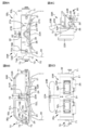
- FIG. 3A is a schematic cross-sectional view of a support member and an image forming apparatus that constitute the display device of Example 1
- FIG. 3B is a schematic cross-sectional view of the support member
- FIG. 1 is a schematic plan view of an image forming apparatus.
- FIG. 4A and 4B are a schematic cross-sectional view of the supporting member and the image forming apparatus constituting the display device of Example 1 taken along arrow A′-A ′ in FIG. 3A, and an arrow in FIG. 3B of the supporting member.
- FIG. 6 is a schematic cross-sectional view along B′-B ′.
- FIG. 5A is a schematic cross-sectional view of the support member and the image forming apparatus that constitute the display device of Example 2
- FIG. 5B is a schematic cross-sectional view of the support member
- FIG. FIG. 5D is a schematic plan view of the image forming apparatus
- FIG. 5D is a schematic cross-sectional view of the support member and the image forming apparatus along the arrow DD in FIG. 5A.
- FIG. 6A is a schematic cross-sectional view of a support member and an image forming apparatus that constitute a display device of Example 3
- FIG. 6B is a schematic plan view of the support member and the image forming apparatus
- FIG. FIG. 10 is a schematic cross-sectional view of a support member and an image forming apparatus that constitute a modification of the display device of Example 3.
- FIG. 7 is a perspective view of a part of the display device according to the first embodiment.
- 8A, FIG. 8B, FIG. 8C, and FIG. 8D are a bottom view, a top view, a right side view, and a rear view, respectively, of the display device of Example 1.
- 9A, 9B, and 9C are diagrams showing how images from the image forming apparatus are formed by various lens groups.
- FIG. 10 is a conceptual diagram of a modification of the display device according to the first embodiment.
- FIG. 11 is a conceptual diagram of a reflecting mirror and the like for explaining the arrangement state of the reflecting mirrors constituting the optical system.
- 12A and 12B are conceptual diagrams of the reflecting mirror and the like for explaining the arrangement state of the reflecting mirrors constituting the optical system, following FIG.
- Example 1 display device of the present disclosure
- Example 2 Modification of Example 1 4
- Example 3 modification of Example 2
- the degree of curvature along the X direction of the support surface of the support member can be larger than the degree of curvature along the Y direction. That is, when the degree of curvature is represented by an average radius of curvature, the average radius of curvature along the X direction of the support surface of the support member can be smaller than the average radius of curvature along the Y direction.
- the first direction or the X direction corresponds to the horizontal direction of the image finally reaching the observer's pupil, and the second direction or the Y direction finally reaches the observer's pupil. It is possible to adopt a form corresponding to the vertical direction.
- the X direction and the Y direction may be orthogonal or may not be orthogonal.
- the support member includes a pressing member
- the outer shape of the image forming apparatus is a rectangular shape
- the outer peripheral portion of the image forming apparatus extending along the X direction may be fixed to the support member by a pressing member.
- the outer peripheral portion of the image forming apparatus refers to an area (so-called frame area) between the end of the image forming apparatus and the end of the display area of the image forming apparatus.
- the outer shape of the image forming apparatus is a rectangular shape
- the outer peripheral portion of the image forming apparatus extending along the X direction may be sandwiched between support members. However, it is not limited to these forms.
- the image forming apparatus may be fixed to the support member using an adhesive.
- the support member may be made of, for example, various plastic materials including ABS resin, a composite material such as Unitate (registered trademark, manufactured by Unitika Ltd.) and FRP, a metal material such as carbon fiber and aluminum, and an alloy material.
- the outer shape of the image forming apparatus is a rectangular shape
- the wiring may extend to the outside from the outer periphery of the image forming apparatus extending along the Y direction.
- a flexible printed wiring board FPC
- the connection portion and the wiring provided on the outer peripheral portion of the image forming apparatus may be connected based on a known method.
- the optical system receives the reflecting mirror that reflects the image from the image forming device and the image reflected by the reflecting mirror.
- the lens group can be configured by a lens group.
- the lens group is arranged between the observer's pupil and the reflecting mirror, and the image forming apparatus can be arranged above the reflecting mirror.
- the lens group includes one group and three lenses, the second lens has negative power, and the refractive index of the material constituting the second lens is first.
- the refractive index of the material constituting the second lens and the third lens can be larger, and the first lens and the third lens can have a positive power. it can.
- the second lens is a meniscus lens.
- the lens group has a telecentric optical system, specifically, a configuration in which the reflecting mirror side is a telecentric optical system.
- the display device including the preferable modes and configurations described above may include a left-eye image display device and a right-eye image display device.
- a left-eye image display device and a right-eye image display device As an overlap (binocular viewing angle) of the horizontal visual field in the left-eye image display device and the horizontal visual field in the right-eye image display device, 45 degrees to 75 degrees can be exemplified.
- the display device having such a configuration further includes an inter-image display device distance adjustment device that adjusts the distance between the left-eye image display device and the right-eye image display device. Is preferred. By providing the inter-image display device distance / adjustment device, it is easy to deal with observers with different pupil distances.
- the image display apparatus includes one image forming apparatus, an optical system that guides an image from the one image forming apparatus to each of the right pupil and the left pupil of the observer, and a support that supports the image forming apparatus.
- the optical system can be composed of at least a left-eye reflecting mirror and lens group, and a right-eye reflecting mirror and lens group, for example.
- the image forming device may be any type of image forming device as long as it is a flexible image forming device.
- it can, it is preferable to comprise from an organic electroluminescent display device (organic EL display device).
- organic EL display device itself can be an organic EL display device having a known configuration and structure.
- the frame can be mounted on the observer's head.
- the present invention is not limited to such a form.
- the frame may be attached to an arm extending from a ceiling or a wall, or may be attached to a movable robot arm.
- the motion of the observer's head may be detected by a sensor so that the motion of the frame follows the motion of the viewer's head.
- the frame When the frame is configured to be attached to the observer's head, the frame can be attached to the observer's head, and the image display device can be attached to the structure and structure.
- the frame may be configured to include a front portion disposed in front of the observer and side portions extending from both ends of the front portion.
- the image display device is attached to the frame.
- the image display device is attached to a lower portion of the front portion and attached to a holding member extending in a substantially horizontal direction.
- it is desirable that a forehead contact with the observer's forehead is attached to the upper portion of the front portion from the viewpoint of improving the attachment feeling of the image display device of the observer.
- the length L X of the display area of the image forming device along the X direction can be exemplified as 83 mm to 130 mm.
- Examples of the number of pixels of the image forming apparatus include 320 ⁇ 240, 432 ⁇ 240, 640 ⁇ 480, 1024 ⁇ 768, 1920 ⁇ 1080, and the like.
- Examples of the horizontal viewing angle (one-eye viewing angle) of the image display device include 100 degrees to 120 degrees.
- a virtual plane including both the pupils of the observer and infinity is the xy plane
- a straight line connecting both the pupils of the observer is an x axis (specifically, a straight line connecting both the pupils of the observer
- the axis line from the observer's right eye pupil to the left eye pupil is the x axis
- the optical axis of the observer right eye is the y axis (specifically, the axis line orthogonal to the x axis and toward the lens group side is y-axis)
- the point of the reflecting mirror where the optical axis (optical principal axis) of the lens group constituting the optical system of the right-eye image display device collides with the reflecting mirror is defined as the “right-eye reflecting mirror optical axis collision point”.
- the reflecting mirrors constituting the optical system of the ophthalmic image display device are arranged in parallel (perpendicularly) to the xz plane (see FIG. 11), and further pass through the optical axis collision point of the right-eye reflector.
- the axis on the reflector parallel to the xy plane is the ⁇ axis
- the axis on the reflector that passes through the optical axis collision point for the right eye and is orthogonal to the ⁇ axis is the ⁇ axis (see FIG.
- the image forming apparatus and the optical system of the image display apparatus for the left eye are parallel to the yz plane through the midpoint of the line segment connecting the pupils of both the image forming apparatus and the optical system of the image display apparatus for the right eye and the observer. It can be set as the form arrange
- the angle ⁇ 3 formed by the axis ⁇ ′ axis and the y axis when the ⁇ axis is projected onto the xy plane, the angle ⁇ 1 , the angle ⁇
- Table 1 An example of the relationship of 2 is shown in Table 1 below.
- the angle ⁇ 3 has a positive value in the ( ⁇ x, y) quadrant (see FIGS. 11 and 12A).
- the optical axis (optical principal axis) of the lens group preferably intersects the center of the observer's pupil.
- the image forming apparatus is preferably disposed above the reflecting mirror.
- a point where the optical axis of the lens group is reflected by the reflecting mirror and collides with the image forming apparatus is defined as an image forming apparatus optical axis collision point
- a virtual plane in contact with the image forming apparatus optical axis collision point is defined as an XY plane.
- the outer shape of the display area is rectangular, and the X direction and the Y direction are orthogonal to each other.
- the image forming apparatus passes through the optical axis collision point, the axis parallel to the X direction is the X axis, and the axis parallel to the Y direction is The Y axis is assumed, and the (X, Y, Z) coordinates of the optical axis collision point of the image forming apparatus are (0, 0, 0).
- Examples of the curved state of the image forming apparatus include a curved surface represented by an aspheric function, a spherical surface, a spheroidal surface, a rotating hyperboloid, and a rotating paraboloid.
- the image forming apparatus is curved along the side surface of the cylinder.
- the degree of curvature of the image forming apparatus is expressed by an average curvature radius
- the value of the average curvature radius may be constant or may vary.
- a display device having an image display device with a different degree of curvature of the image forming device may be prepared, and an appropriate display device may be provided according to the visual acuity of the observer, or the degree of curvature of the image forming device. It is good also as a structure and structure which can be made variable.
- the relationship between the radius of the side surface of the cylinder and the diopter value when the image forming apparatus is assumed to be curved following the side surface of the cylinder is illustrated in Table 2 below, but is not limited thereto.
- Example 1 relates to a display device of the present disclosure and an image display device of the present disclosure.
- a perspective view of the main part of the display device when the observer wears the display device is shown in FIG. 1, and a perspective view of the main part of the display device when the observer wearing the display device is viewed from the front is shown in FIG.
- FIG. 2B shows a perspective view of the main part of the display device as viewed from the side of the observer wearing the display device.
- 3A and 4A are schematic cross-sectional views of the support member and the image forming apparatus, and FIGS. 3B and 4B are schematic cross-sectional views of the support member.
- a plan view is shown in FIG. 3C.
- 3A and 3B are schematic cross-sectional views along the arrow AA in FIG. 3C.
- FIGS. 4A and 4B are the arrows A′-A ′ in FIG. 3A and the arrows B ′ in FIG. 3B.
- FIG. 6 is a schematic cross-sectional view taken along ⁇ B ′.
- FIG. 7 shows a perspective view of a part of the display device according to the first embodiment. In FIG. 7, illustration of a reflecting mirror, an image forming apparatus, and the like is omitted. Further, FIG. 8A, FIG. 8B, FIG. 8C, and FIG. 8D show a bottom view, a top view, a right side view, and a rear view of the display device according to the first embodiment. Illustration of some of the components of the display device is omitted.
- the display device of Example 1 is (A) Frame 20 and (B) an image display device 30 attached to the frame 20; It has. And the image display apparatus 30 in the display apparatus of Example 1 or the image display apparatus 30 of Example 1 (A) Image forming apparatus 40, (B) an optical system 50 that guides an image from the image forming apparatus 40 to the pupil of the observer 10, and (C) a support member 60 1 that supports the image forming apparatus 40, It has.
- the frame 20 in the display device of the first embodiment is mounted on the head of the observer 10, and more specifically, the display device of the first embodiment is a head mounted display (HMD).
- HMD head mounted display
- the first direction of the image the direction of the support member 60 1 corresponding to the X direction, and the second direction different from the image (specifically a first direction
- the support surface of the support member 60 1 that supports the image forming apparatus 40 is the X direction, the Y direction, the X direction, and the Y direction. It is curved along the direction (specifically, in the first embodiment, it is curved along the X direction), and thus the image forming apparatus 40 is curved. More specifically, the image forming apparatus 40 is curved to follow the support surface of the support member 60 1.
- the outer shape of the image forming apparatus 40 and the outer shape of the display area of the image forming apparatus 40 are rectangular.
- the degree of curvature along the X direction of the support member 60 1 of the support surface 61 is greater than the degree of curvature along the Y direction. That is, when the degree of curvature is expressed by an average radius of curvature, the average radius of curvature along the X direction of the support surface of the support member is smaller than the average radius of curvature along the Y direction.
- the radius of curvature along the X direction of the support surface of the support member is 100 mm, and the radius of curvature along the Y direction is infinite.
- the image forming apparatus 40 is curved along the side surface of the cylinder, and the radius of the side surface of the cylinder is 100 mm.
- the effective focal length of the lens group 52 is 56 mm. The preferable relationship between the radius of the side surface of the cylinder and the effective focal length of the lens group 52 is shown in Table 3 below.
- Support member 60 1 is provided with a pressing member 65, As described above, the outer shape of the image forming apparatus 40 is a rectangular shape, The outer peripheral portion of the image forming apparatus 40 extending along the X direction are fixed to the support member 60 1 by the pressing member 65.
- the support members 60 1 and the presser member 65 is fabricated from aluminum.
- the upper surface and the central portion of the support member 60 1 correspond to the support surface 61, and the outer peripheral portions 62 A and 62 B of the support member 60 1 extending along the Y direction protrude from the support surface 61.
- the portion of the outer peripheral portion 62A facing the support surface 61 is a contact surface 62C, and one edge portion of the image forming apparatus 40 extending along the Y direction is abutted against the contact surface 62C.
- aluminum stopper member 63 is fixed to the upper surface of the support member 60 1 by a screw 64 screwed to the threaded portion 62D formed on the upper surface of the support member 60 1, extending along the Y direction image It is in contact with the other edge of the forming device 40.
- the stop member 63 is provided with a long hole (a long hole elongated in the X direction) through which the screw 64 is passed.
- the image forming apparatus 40 by a retaining member 63, and subjected to compressive forces in the direction of arrow "a" in FIG. 3A, thereby, the image forming apparatus 40, the image forming apparatus 40 of the support member 60 1 Following the support surface 61, it is curved without a gap.
- One end portion 65A of the pressing member 65 is pressing the outer peripheral portion of the image forming apparatus 40 extending along the X direction
- the other end portion 65B of the pressing member 65 includes a bottom surface of the support member 60 1 extending along the X direction engaged and, thereby, the outer peripheral portion of the image forming apparatus 40 extending along the X direction are fixed to the support member 60 1 by the pressing member 65.
- the support surface 61 of the lower surface and the support member 60 1 of the image forming apparatus 40 may be fixed by using an adhesive, in this case, it is also possible to omit the pressing member 65.
- a wiring 41 extends from the outer periphery of the image forming apparatus 40 extending along the Y direction.
- the connection portion provided on the outer peripheral portion of the image forming apparatus 40 and the wiring 41 may be connected based on a known method.
- FIG. 3C illustrates a state in which the wiring 41 extends from one of the outer peripheral portions of the image forming apparatus 40 extending along the Y direction. Both of the outer peripheral portions of the image forming apparatus 40 extending along the Y direction are illustrated.
- the wiring 41 may extend from the terminal.
- the image forming device 40 includes an organic electroluminescence display device (organic EL display device) having a known configuration and structure.
- organic EL display device includes a first substrate, a second substrate, and a large number of light emitting units sandwiched between the first substrate and the second substrate.
- the thickness of the image forming apparatus 40, following the support surface of the support member 60 1 is the thickness that can be bent without any gap, for example, 0.5 mm or less, for example, a 0.2mm to 0.5 mm.
- the number of pixels was set to 1920 ⁇ 1080.
- the display device includes a left-eye image display device 30L and a right-eye image display device 30R.
- the horizontal viewing angle (one-eye viewing angle) in each image display device 30 is 100 degrees
- the horizontal viewing angle in the left-eye image display device 30L and the horizontal viewing angle in the right-eye image display device 30R are 70.
- the total horizontal viewing angle was 130 degrees.
- the length L X of the display area of each image forming apparatus 40 along the X direction was set to 100 mm.
- the vertical viewing angle was 44 degrees.
- the one-eye viewing angle is 120 degrees
- the binocular viewing angle is 70 degrees
- the total horizontal viewing angle is 170 degrees
- the display area of each image forming apparatus 40 is
- the length L X is 126 mm
- the lens group has a mass of “4.6” and an effective focal length of 67.2 mm.
- the frame 20 attached to the head of the observer 10 is made of plastic, and includes a front part 21 disposed in front of the observer 10 and side parts 22 extending from both ends of the front part.
- a hole 22A is provided at the rear end of the side portion 22, and the belt 20 is passed through the hole 22A and the belt is wound around the back of the head of the observer so that the frame 20 is attached to the head of the observer 10. can do.
- An arm 23A extends upward from the upper portion of the front portion 21, and a forehead pad 23B that contacts the forehead of the observer 10 is attached to the tip of the arm 23A. Further, a nose pad portion 24 is disposed on the front portion 21.
- a rear portion of the holding member 25 is attached to the lower end portion of the front portion 21, and a base portion 26 is attached to the front portion of the holding member 25. Further, a pupil / optical system distance / adjustment device 80 described later is attached to the distal end portion of the base portion 26, and a pedestal 71 constituting the pupil / optical system distance / adjustment device 80 is disposed on the base portion 26. It is arranged to be slidable in the front-rear direction.
- An optical system 50L configuring the left-eye image display device 30L is stored in the housing 53L
- an optical system 50R configuring the right-eye image display device 30R is stored in the housing 53R.
- the left-eye image display device 30L is attached to the housing 53L
- the left-eye image display device 30R is attached to the housing 53R
- the housing 53L and the housing 53R are attached to the base 71.
- the optical system 50L and the left-eye image display device 30L, and the optical system 50R and the right-eye image display device 30R are independently slidable on the pedestal 71 in the left-right direction. Is arranged.
- the “front-rear direction” means the direction in which the lens group approaches or moves away from the pupil.
- the “left-right direction” means that the left-eye image display device and the right-eye image display device approach each other. Or the direction away.
- the optical system 50 includes a reflecting mirror 51 that reflects an image from the image forming apparatus 40 and a lens group 52 on which the image reflected by the reflecting mirror 51 enters.
- the reflecting mirror 51R and the lens group 52R constituting the right-eye image display device are attached to the pedestal 71 via the housing 53R, and can slide on the base 26 in the left-right direction.
- the reflecting mirror 51L and the lens group 52L constituting the left-eye image display device are attached to the pedestal 71 via the housing 53L, and can slide on the base portion 26 in the left-right direction.
- the lens group 52 (52R, 52L) is disposed between the pupil of the observer 10 and the reflecting mirror 51 (51R, 51L), and the image forming apparatus 40 is disposed above the reflecting mirror 51.
- the lens group 52 includes one group and three lenses, the second lens has negative power, and the refractive index of the material constituting the second lens is the first and third lenses. It is larger than the refractive index of the material which comprises.
- the first lens and the third lens have positive power.
- the second lens is a meniscus lens. Specifically, the effective focal length of the lens group 52 was 56.01 mm, the rear focal length was 44.64 mm, the front focal length was ⁇ 32.16 mm, and the F number was 14.0. The length of the lens group 52 in the horizontal direction was 36 mm, and the length in the vertical direction was 20 mm.
- the lens group 52 has a telecentric optical system, specifically, a configuration in which the reflecting mirror side is a telecentric optical system.
- the distance between the first lens and the pupil of the observer 10 was 10 mm.
- the mass of this lens group is “1”
- the mass of the lens group when the distance between the first lens and the pupil of the observer 10 is 12 mm is “1.7”.
- FIG. 9A, 9B, and 9C show how images from the image forming apparatus 40 are formed by various lens groups.
- the lens group shown in FIG. 9A is a lens group of a telecentric optical system.
- FIG. 9B shows a lens group having a configuration close to that of a telecentric optical system, and
- FIG. 9C shows a normal lens group.
- Example 1 the lens group shown in FIG. 9A was used.
- the display device further includes the inter-image display device distance / adjustment device 70 that adjusts the distance between the left-eye image display device 30L and the right-eye image display device 30R.
- the inter-image display device distance / adjustment device 70 includes a pedestal 71, a feed screw mechanism 73 attached to a side surface 72 located outside the pedestal 71, and a housing 53 that can slide on the pedestal 71 from below.
- Tap hole 75A for fixing with force guide grooves 74B and 76B provided in housing 53, guide groove 75B provided in base 71, pin 74A provided in base 71 and engaged with guide grooves 74B and 76B , 76A.
- the guide grooves 75B, 75B, and 76B extend in the left-right direction.
- the housing 53 (the housing 53L or the housing 53R) moves in the left-right direction with respect to the base portion 26.
- the housing 53 is reliably moved in the left-right direction by the engagement of the pins 74A, the tap holes 75A, the pins 76A and the guide grooves 74B, 75B, 76B.
- the moving distance in the horizontal direction of the casings 53L and 53R was ⁇ 5 mm.
- a combination of a latch mechanism and a knob or a rack and pinion mechanism can be used.
- the casings 53R and 53L extend further upward than shown in FIGS. 8A, 8B, 8C, and 8D, and support members that support the image forming apparatus 40 in portions of the casings 53R and 53L that extend upward. Although 60 1 is attached, these illustrations are omitted.
- the display device further includes a pupil / optical system distance / adjustment device 80 that adjusts the distance between the pupil of the observer 10 and the lens group 52.
- the pupil / optical system distance / adjustment device 80 is provided on the side wall 82 attached to the distal end portion of the second holding member 26, the feed screw mechanism 83 attached to the side wall 82, and the base 71.
- a key 27A that extends downward from 71
- a guide groove 27B that engages with the key 27A
- a fastening portion 27C that holds the pedestal 71 at a level slidable with respect to the base 26.
- the movement of the pedestal 71 is reliably performed in the front-rear direction by the engagement between the key 27A and the guide groove 27B.
- the moving distance of the pedestal 71 in the front-rear direction was ⁇ 4 mm.
- a combination of a latch mechanism and a knob, or a rack and pinion mechanism can be used.
- the image forming apparatus can be curved based on a simple configuration and structure. Specifically, it can be curved following the support surface of the support member. Since the image forming apparatus is curved, the optical path length difference between the optical path length of the light emitted from the central portion of the image forming apparatus and the optical path length of the light emitted from the outer edge portion of the image forming apparatus is calculated. As a result of being able to be reduced, for example, it is possible to achieve a large viewing angle while suppressing an increase in the size of the lens group constituting the optical system.
- Example 2 is a modification of Example 1.
- FIG. 5A shows a schematic cross-sectional view of the support member and the image forming apparatus constituting the display device or the image display apparatus of Example 2
- FIG. 5B shows a schematic cross-sectional view of the support member.
- FIG. 5C shows a schematic plan view of the apparatus
- FIG. 5D shows a schematic cross-sectional view of the support member and the image forming apparatus along the arrow DD in FIG. 5A.
- the outer peripheral portion of the image forming apparatus 40 extending along the X direction is sandwiched between support members 602.
- the support member 60 2 is composed of a lower member 66A and an upper member 66B.
- a kind of frame member is formed, and the support member 60 2 is formed on the inner side surface of the support member 60 2.
- a groove 66C is formed.
- the outer peripheral portion of the image forming apparatus 40 extending along the X direction is fitted into the groove 66C.
- the lower member 66A and the upper member 66B may be fixed to each other with a screw (not shown), or may be fixed to each other using an adhesive.
- the outer peripheral portion of the image forming apparatus 40 extending along the X direction it is preferable to fix the outer peripheral portion of the image forming apparatus 40 extending along the X direction to the groove portion 66C with an adhesive.
- the outer peripheral portion of the image forming apparatus 40 extending along the X direction not only the outer peripheral portion of the image forming apparatus 40 extending along the X direction but also the outer peripheral portion of the image forming apparatus 40 extending along the Y direction is sandwiched between the support members 60 2 .
- only the outer peripheral portion of the image forming apparatus 40 extending along the X direction may be sandwiched by the support member 60 2.
- the configuration and structure of the display device or image display device according to the second embodiment can be the same as the configuration and structure of the display device or image display device described in the first embodiment. Is omitted.
- Example 3 is a modification of Example 2. Even in the third embodiment, the image forming apparatus 40 is curved. However, unlike Example 2, the degree of bending was variable.
- FIG. 6A shows a schematic cross-sectional view of the support member and the image forming apparatus constituting the display device or image display apparatus of Example 3, and
- FIG. 6B shows a schematic plan view of the support member and the image forming apparatus.
- the third embodiment there is a gap between the groove 66C and the outer peripheral portion of the image forming apparatus 40 extending along the X direction. Then, the side surface extending along the X direction of the support member 60 3, projections 67A and threaded portion 67B is provided. Support member 60 3 is stored in a housing (not shown) the upper is open. The housing is attached to the upper part of the casings 53R and 53L. A hole for fitting with the protrusion 67A is formed on the side surface of the housing. In addition, a guide groove extending substantially vertically is formed in a portion of the side surface of the housing that faces the screwing portion 67B, and a screw is inserted into the guide groove and supported by screwing with the screwing portion 67B.
- the member 60 3 can be fixed to the side of the housing.
- the force applied to the support member 60 3 and further to the image forming apparatus 40 in the X direction changes.
- the center of the protrusion 67A is indicated by a cross.
- the locus of the circle of the threaded portion 67B around the center of the protrusion 67A is indicated by a dotted line “a”, and the locus of the center of the through hole is indicated by a solid line “b”.
- the distance from the center of the protrusion 67A to the center of the threaded portion 67B is shortened. Therefore, a compressive force is applied in the X direction of the support member 60 3 and the image forming apparatus 40. As a result, the degree of curvature of the image forming apparatus 40 changes. Since there is a gap between the groove 66C and the outer periphery of the image forming apparatus 40 extending along the X direction, it is possible to allow a change in the degree of curvature of the image forming apparatus 40. After determining the degree of curvature of the image forming apparatus 40, the gap may be filled with an appropriate material (for example, shim). Alternatively, an elastic material may be sandwiched in advance in the gap.
- an appropriate material for example, shim
- FIG. 6C a schematic cross-sectional view of the support member and the image forming apparatus constituting the display device of the third embodiment or a modification of the image display device is used.
- the force applied in the X direction of the support member 60 3 and further the image forming apparatus 40 may be changed by the push screw 68 ⁇ / b> B for moving the image forming apparatus 40.
- the present disclosure has been described based on the preferred embodiments, the present disclosure is not limited to these embodiments.
- the configurations and structures of the image display apparatus and the image forming apparatus described in the embodiments are examples and can be changed as appropriate.
- the projector can also be configured by a combination of the image forming apparatus described in the embodiment and a support member that supports the image forming apparatus.
- the image display device has one image forming device (represented by 40R and 40L) as shown in a conceptual diagram in FIG. 10, and images from this image forming device are the right pupil and left pupil of the observer.
- the optical system may include at least a left-eye reflecting mirror, for example, and an optical system that guides the image forming apparatus and a support member (not shown) that supports the image forming apparatus. What is necessary is just to comprise from 51L, the lens group 52L, and the reflective mirror 51R and lens group 52R for right eyes.
- this indication can also take the following structures.
- ⁇ Display device >> (B) Frame and (B) an image display device attached to the frame;
- a display device comprising: The image display device (A) an image forming apparatus, (B) an optical system for guiding an image from the image forming apparatus to the observer's pupil; and (C) a support member that supports the image forming apparatus; With Support for supporting the image forming apparatus when the direction of the support member corresponding to the first direction of the image is the X direction and the direction of the support member corresponding to the second direction of the image different from the first direction is the Y direction.
- the support surface of the member is curved along the X direction, the Y direction, or the X direction and the Y direction, and the image forming apparatus is curved.
- the support member includes a pressing member,
- the outer shape of the image forming apparatus is a rectangular shape,
- the display device according to [1] or [2], wherein an outer peripheral portion of the image forming apparatus extending along the X direction is fixed to a support member by a pressing member.
- the outer shape of the image forming apparatus is a rectangular shape, The display device according to [1] or [2], wherein an outer peripheral portion of the image forming apparatus extending along the X direction is sandwiched between support members.
- the outer shape of the image forming apparatus is a rectangular shape, The display device according to any one of [1] to [4], wherein the wiring extends outside from an outer peripheral portion of the image forming apparatus extending along the Y direction.
- the lens group is disposed between the observer's pupil and the reflecting mirror, The display device according to [6], wherein the image forming apparatus is disposed above the reflecting mirror.
- the lens group is composed of one lens group and three lenses.
- the second lens has negative power,
- the display device according to [8], wherein the first lens and the third lens have positive power.
- the display device according to [10], further including a distance / adjustment device between image display devices that adjusts a distance between the image display device for the left eye and the image display device for the right eye.
- the display device according to any one of [1] to [11], wherein the image forming apparatus includes an organic electroluminescence display device.
- the frame is attached to an observer's head.
- Image display device >> (A) an image forming apparatus, (B) an optical system for guiding an image from the image forming apparatus to the observer's pupil; and (C) a support member that supports the image forming apparatus; With Support for supporting the image forming apparatus when the direction of the support member corresponding to the first direction of the image is the X direction and the direction of the support member corresponding to the second direction of the image different from the first direction is the Y direction.
- the support surface of the member is curved along the X direction, the Y direction, or the X direction and the Y direction, and the image forming apparatus is curved.
Landscapes
- Physics & Mathematics (AREA)
- General Physics & Mathematics (AREA)
- Optics & Photonics (AREA)
Priority Applications (4)
| Application Number | Priority Date | Filing Date | Title |
|---|---|---|---|
| JP2015511197A JP6547622B2 (ja) | 2013-04-11 | 2014-03-26 | 画像表示装置及び表示装置 |
| US14/782,054 US10663736B2 (en) | 2013-04-11 | 2014-03-26 | Image display device and display apparatus |
| CN201480002217.4A CN104583842B (zh) | 2013-04-11 | 2014-03-26 | 图像显示装置和显示设备 |
| EP14783184.6A EP2985652A4 (en) | 2013-04-11 | 2014-03-26 | IMAGE DISPLAY DEVICE AND DISPLAY DEVICE |
Applications Claiming Priority (2)
| Application Number | Priority Date | Filing Date | Title |
|---|---|---|---|
| JP2013-082828 | 2013-04-11 | ||
| JP2013082828 | 2013-04-11 |
Publications (1)
| Publication Number | Publication Date |
|---|---|
| WO2014168010A1 true WO2014168010A1 (ja) | 2014-10-16 |
Family
ID=51689422
Family Applications (1)
| Application Number | Title | Priority Date | Filing Date |
|---|---|---|---|
| PCT/JP2014/058605 WO2014168010A1 (ja) | 2013-04-11 | 2014-03-26 | 画像表示装置及び表示装置 |
Country Status (5)
| Country | Link |
|---|---|
| US (1) | US10663736B2 (zh) |
| EP (1) | EP2985652A4 (zh) |
| JP (1) | JP6547622B2 (zh) |
| CN (1) | CN104583842B (zh) |
| WO (1) | WO2014168010A1 (zh) |
Cited By (2)
| Publication number | Priority date | Publication date | Assignee | Title |
|---|---|---|---|---|
| WO2016027539A1 (ja) * | 2014-08-18 | 2016-02-25 | ソニー株式会社 | 画像表示装置及び表示装置 |
| JP2021192555A (ja) * | 2015-02-27 | 2021-12-16 | 株式会社ソニー・インタラクティブエンタテインメント | ヘッドマウントディスプレイ |
Families Citing this family (23)
| Publication number | Priority date | Publication date | Assignee | Title |
|---|---|---|---|---|
| JP5499854B2 (ja) | 2010-04-08 | 2014-05-21 | ソニー株式会社 | 頭部装着型ディスプレイにおける光学的位置調整方法 |
| JP5434848B2 (ja) | 2010-08-18 | 2014-03-05 | ソニー株式会社 | 表示装置 |
| JP5780129B2 (ja) | 2011-11-22 | 2015-09-16 | ソニー株式会社 | 光ビーム伸長装置、画像表示装置及び光学装置 |
| JP5879973B2 (ja) | 2011-11-30 | 2016-03-08 | ソニー株式会社 | 光反射部材、光ビーム伸長装置、画像表示装置及び光学装置 |
| JP6003903B2 (ja) | 2012-01-24 | 2016-10-05 | ソニー株式会社 | 表示装置 |
| JP6145966B2 (ja) | 2012-05-09 | 2017-06-14 | ソニー株式会社 | 表示装置 |
| CN104204905B (zh) | 2013-01-10 | 2016-11-23 | 索尼公司 | 图像显示设备、图像生成装置以及透射式空间光调制装置 |
| JP6123342B2 (ja) | 2013-02-20 | 2017-05-10 | ソニー株式会社 | 表示装置 |
| CN108132537B (zh) | 2013-04-11 | 2021-03-16 | 索尼公司 | 显示设备 |
| JP6367529B2 (ja) | 2013-06-25 | 2018-08-01 | ソニー株式会社 | 表示装置、表示制御方法、表示制御装置、および電子機器 |
| US10302946B2 (en) | 2013-07-04 | 2019-05-28 | Sony Corporation | Display apparatus |
| JP6311714B2 (ja) | 2013-07-16 | 2018-04-18 | ソニー株式会社 | 表示装置 |
| US9952435B2 (en) | 2013-07-16 | 2018-04-24 | Sony Corporation | Display apparatus having curved image forming apparatus |
| JP2015148782A (ja) | 2014-02-10 | 2015-08-20 | ソニー株式会社 | 画像表示装置及び表示装置 |
| JP6314518B2 (ja) | 2014-02-10 | 2018-04-25 | ソニー株式会社 | 画像表示装置及び表示装置 |
| JP6201836B2 (ja) | 2014-03-14 | 2017-09-27 | ソニー株式会社 | 光学装置及びその組立方法、ホログラム回折格子、表示装置並びにアライメント装置 |
| JP6391952B2 (ja) | 2014-03-17 | 2018-09-19 | ソニー株式会社 | 表示装置及び光学装置 |
| JP2015184560A (ja) | 2014-03-25 | 2015-10-22 | ソニー株式会社 | 導光装置、画像表示装置及び表示装置 |
| JP2015184561A (ja) | 2014-03-25 | 2015-10-22 | ソニー株式会社 | 導光装置、画像表示装置及び表示装置 |
| GB2557942A (en) * | 2016-12-19 | 2018-07-04 | Sharp Kk | Apparatus to achieve compact head mounted display with reflectors and eyepiece element |
| WO2018163035A1 (en) * | 2017-03-08 | 2018-09-13 | 3M Innovative Properties Company | Optical system |
| CN107861247B (zh) * | 2017-12-22 | 2020-08-25 | 联想(北京)有限公司 | 光学部件及增强现实设备 |
| CN109031593B (zh) * | 2018-08-03 | 2021-02-23 | 诚瑞光学(苏州)有限公司 | 投影镜头 |
Citations (8)
| Publication number | Priority date | Publication date | Assignee | Title |
|---|---|---|---|---|
| JPS62105184A (ja) * | 1985-10-31 | 1987-05-15 | 日本精機株式会社 | 液晶表示装置 |
| JPH05134208A (ja) | 1991-11-12 | 1993-05-28 | Olympus Optical Co Ltd | 像観察装置 |
| JPH063641A (ja) * | 1992-06-19 | 1994-01-14 | Sharp Corp | ディスプレイ・パネル |
| JPH0882762A (ja) * | 1994-07-15 | 1996-03-26 | Sega Enterp Ltd | 頭部搭載型映像表示装置およびこれを用いた映像表示システム |
| JPH10206786A (ja) * | 1997-01-17 | 1998-08-07 | Sanyo Electric Co Ltd | 頭部装着型の画像表示装置 |
| JP2002049021A (ja) * | 2000-08-03 | 2002-02-15 | Seiko Instruments Inc | 腕携帯情報機器 |
| JP2002341792A (ja) * | 2001-05-18 | 2002-11-29 | Minolta Co Ltd | 表示パネル及び該パネルを備えた曲面型表示装置 |
| JP2005099788A (ja) * | 2003-09-03 | 2005-04-14 | Carl Zeiss Ag | 非球面を含む画像形成光学系を備えるhmdデバイス |
Family Cites Families (96)
| Publication number | Priority date | Publication date | Assignee | Title |
|---|---|---|---|---|
| US5486841A (en) * | 1992-06-17 | 1996-01-23 | Sony Corporation | Glasses type display apparatus |
| JPH06194598A (ja) | 1992-12-25 | 1994-07-15 | Olympus Optical Co Ltd | 頭部装着型ディスプレイ装置 |
| US5473365A (en) | 1992-12-25 | 1995-12-05 | Olympus Optical Co., Ltd. | Head-mounted image display apparatus in which a system is capable of changing aspect ratio of observed image |
| JP3263062B2 (ja) | 1993-04-27 | 2002-03-04 | オリンパス光学工業株式会社 | 視覚表示装置 |
| JPH0772420A (ja) | 1993-09-03 | 1995-03-17 | Casio Comput Co Ltd | 画像表示装置 |
| JP3328028B2 (ja) | 1993-10-19 | 2002-09-24 | オリンパス光学工業株式会社 | 頭部装着型映像表示装置 |
| US5793339A (en) | 1993-11-11 | 1998-08-11 | Olympus Optical Co., Ltd. | Visual display apparatus |
| GB9403925D0 (en) | 1994-03-01 | 1994-04-20 | Virtuality Entertainment Ltd | Optical system |
| EP0908754A3 (en) | 1994-04-21 | 2000-04-12 | Sega Enterprises, Ltd. | Head mounted display |
| JPH07318850A (ja) | 1994-05-23 | 1995-12-08 | Olympus Optical Co Ltd | 頭部装着型映像表示装置 |
| WO1996000406A1 (fr) | 1994-06-23 | 1996-01-04 | Seiko Epson Corporation | Dispositif de presentation monte sur des lunettes |
| JPH08166557A (ja) | 1994-06-23 | 1996-06-25 | Seiko Epson Corp | 頭部装着型表示装置 |
| JPH08191462A (ja) | 1995-01-10 | 1996-07-23 | Olympus Optical Co Ltd | 立体映像再生装置および立体撮影装置 |
| WO1996028756A1 (en) * | 1995-03-09 | 1996-09-19 | Geo-Centers, Inc. | Conducting substrate, liquid crystal device made therefrom and liquid crystalline composition in contact therewith |
| JP3286133B2 (ja) | 1995-11-09 | 2002-05-27 | シャープ株式会社 | 拡大用レンズとディスプレイ装置 |
| JPH0949999A (ja) * | 1995-12-29 | 1997-02-18 | Fujiyama Teruki | ディスプレイ装置 |
| TW395121B (en) * | 1996-02-26 | 2000-06-21 | Seiko Epson Corp | Personal wearing information display device and the display method using such device |
| JPH10104548A (ja) | 1996-09-27 | 1998-04-24 | Nikon Corp | ヘッドマウントディスプレイ装置 |
| US5983073A (en) * | 1997-04-04 | 1999-11-09 | Ditzik; Richard J. | Modular notebook and PDA computer systems for personal computing and wireless communications |
| US6100862A (en) | 1998-04-20 | 2000-08-08 | Dimensional Media Associates, Inc. | Multi-planar volumetric display system and method of operation |
| US6529331B2 (en) * | 2001-04-20 | 2003-03-04 | Johns Hopkins University | Head mounted display with full field of view and high resolution |
| US6522474B2 (en) * | 2001-06-11 | 2003-02-18 | Eastman Kodak Company | Head-mounted optical apparatus for stereoscopic display |
| US7114500B2 (en) | 2001-08-28 | 2006-10-03 | Marctec, Llc | Surgical draping system |
| EP1565782A1 (en) * | 2002-11-22 | 2005-08-24 | Koninklijke Philips Electronics N.V. | Method of manufacturing a curved display |
| WO2004061519A1 (ja) | 2002-12-24 | 2004-07-22 | Nikon Corporation | ヘッドマウントディスプレイ |
| JP2004233867A (ja) | 2003-01-31 | 2004-08-19 | Nikon Corp | 画像表示装置 |
| CN100416340C (zh) | 2003-04-25 | 2008-09-03 | 微型光学公司 | 双目镜观察系统 |
| US6879443B2 (en) | 2003-04-25 | 2005-04-12 | The Microoptical Corporation | Binocular viewing system |
| US7495638B2 (en) * | 2003-05-13 | 2009-02-24 | Research Triangle Institute | Visual display with increased field of view |
| JP2004139132A (ja) | 2004-01-08 | 2004-05-13 | Seiko Epson Corp | 画像表示装置及び頭部装着型表示装置 |
| GB2413717A (en) * | 2004-04-28 | 2005-11-02 | Graeme Donald Robertson | A spherical visual display |
| US20060056069A1 (en) * | 2004-09-10 | 2006-03-16 | Premier Image Technology Corporation | Photographic lens with fixed focal length |
| JP4933056B2 (ja) | 2005-05-11 | 2012-05-16 | キヤノン株式会社 | 画像表示装置及びそれを用いた撮像装置 |
| JP2007086500A (ja) | 2005-09-22 | 2007-04-05 | Sony Corp | 表示装置 |
| IL172797A (en) | 2005-12-25 | 2012-09-24 | Elbit Systems Ltd | Real-time image scanning and processing |
| EP1826604B1 (en) * | 2006-01-31 | 2015-12-23 | Semiconductor Energy Laboratory Co., Ltd. | Display device |
| JP5074777B2 (ja) | 2006-05-22 | 2012-11-14 | キヤノン株式会社 | 撮像機能付表示装置、画像処理装置、画像処理方法、および、画像表示システム |
| US8035576B2 (en) | 2007-02-20 | 2011-10-11 | Canon Kabushiki Kaisha | Head-mounted display and head-mounted video display |
| JP2008224850A (ja) | 2007-03-09 | 2008-09-25 | Shimadzu Corp | 表示装置 |
| JP5094250B2 (ja) * | 2007-07-10 | 2012-12-12 | 株式会社ジャパンディスプレイイースト | 表示装置 |
| JP2009134276A (ja) * | 2007-11-05 | 2009-06-18 | Panasonic Corp | 表示装置、表示方法、表示プログラム、集積回路、眼鏡型ヘッドマウントディスプレイ、自動車、単眼鏡、及び据置型ディスプレイ |
| JP2009128565A (ja) | 2007-11-22 | 2009-06-11 | Toshiba Corp | 表示装置、表示方法及びヘッドアップディスプレイ |
| US7988313B2 (en) * | 2008-03-20 | 2011-08-02 | Kutnyak Mark R | Illuminated headgear |
| JP2010039441A (ja) | 2008-08-08 | 2010-02-18 | Hitachi Displays Ltd | 液晶表示装置 |
| JP2010072502A (ja) | 2008-09-22 | 2010-04-02 | Hitachi Displays Ltd | 液晶表示装置 |
| JP5388534B2 (ja) | 2008-10-09 | 2014-01-15 | キヤノン株式会社 | 画像処理装置およびその方法、頭部装着型ディスプレイ、プログラム、記録媒体 |
| JP5321011B2 (ja) | 2008-11-25 | 2013-10-23 | ソニー株式会社 | 画像信号処理装置、画像信号処理方法および画像投射装置 |
| JP5191920B2 (ja) | 2009-02-04 | 2013-05-08 | 株式会社ジャパンディスプレイイースト | 液晶表示装置 |
| US8004769B2 (en) | 2009-03-05 | 2011-08-23 | Nabes, Llc | Binocular apparatus and system |
| EP2244117B1 (en) | 2009-04-24 | 2017-05-31 | Ricoh Company, Ltd. | Zoom lens unit |
| US20120212484A1 (en) | 2010-02-28 | 2012-08-23 | Osterhout Group, Inc. | System and method for display content placement using distance and location information |
| JP5678460B2 (ja) | 2010-04-06 | 2015-03-04 | ソニー株式会社 | 頭部装着型ディスプレイ |
| JP5499854B2 (ja) | 2010-04-08 | 2014-05-21 | ソニー株式会社 | 頭部装着型ディスプレイにおける光学的位置調整方法 |
| JP5494153B2 (ja) | 2010-04-08 | 2014-05-14 | ソニー株式会社 | 頭部装着型ディスプレイにおける画像表示方法 |
| JP5434848B2 (ja) | 2010-08-18 | 2014-03-05 | ソニー株式会社 | 表示装置 |
| JP2012079291A (ja) | 2010-09-08 | 2012-04-19 | Namco Bandai Games Inc | プログラム、情報記憶媒体及び画像生成システム |
| JP2012063633A (ja) | 2010-09-16 | 2012-03-29 | Olympus Corp | 頭部装着型表示装置 |
| US20140276207A1 (en) * | 2010-10-25 | 2014-09-18 | Endosee Corporation | Method and appartus for hysteroscopy and endometrial biopsy |
| JP5598281B2 (ja) | 2010-11-19 | 2014-10-01 | ソニー株式会社 | 投射型表示システム |
| BR112013014975A2 (pt) * | 2010-12-16 | 2020-08-11 | Lockheed Martin Corporation | exibição de colimação com lentes de pixel |
| US8743463B2 (en) | 2011-02-04 | 2014-06-03 | Seiko Epson Corporation | Virtual image display |
| JP5655626B2 (ja) | 2011-02-24 | 2015-01-21 | ソニー株式会社 | 画像処理装置、および画像処理方法、並びにプログラム |
| JP5121962B2 (ja) * | 2011-03-31 | 2013-01-16 | 株式会社東芝 | 電子機器 |
| US20150077312A1 (en) | 2011-05-13 | 2015-03-19 | Google Inc. | Near-to-eye display having adaptive optics |
| TW201300838A (zh) | 2011-06-28 | 2013-01-01 | Era Optoelectronics Inc | 浮在空中的虛擬實像顯示裝置 |
| JP5851157B2 (ja) | 2011-08-25 | 2016-02-03 | リコー光学株式会社 | 接眼レンズ系および画像観察装置 |
| JP5780129B2 (ja) | 2011-11-22 | 2015-09-16 | ソニー株式会社 | 光ビーム伸長装置、画像表示装置及び光学装置 |
| JP5979507B2 (ja) | 2011-11-24 | 2016-08-24 | パナソニックIpマネジメント株式会社 | 頭部装着型ディスプレイ装置 |
| JP5879973B2 (ja) | 2011-11-30 | 2016-03-08 | ソニー株式会社 | 光反射部材、光ビーム伸長装置、画像表示装置及び光学装置 |
| US9459457B2 (en) | 2011-12-01 | 2016-10-04 | Seebright Inc. | Head mounted display with remote control |
| JP6003903B2 (ja) | 2012-01-24 | 2016-10-05 | ソニー株式会社 | 表示装置 |
| JP6035793B2 (ja) | 2012-03-14 | 2016-11-30 | ソニー株式会社 | 画像表示装置及び画像生成装置 |
| JP5990998B2 (ja) | 2012-04-23 | 2016-09-14 | セイコーエプソン株式会社 | 虚像表示装置 |
| JP6145966B2 (ja) | 2012-05-09 | 2017-06-14 | ソニー株式会社 | 表示装置 |
| KR102041883B1 (ko) * | 2012-07-09 | 2019-11-08 | 삼성디스플레이 주식회사 | 커브드 프레임 및 이를 갖는 커브드 표시장치 |
| US9250445B2 (en) | 2012-08-08 | 2016-02-02 | Carol Ann Tosaya | Multiple-pixel-beam retinal displays |
| US20140104692A1 (en) | 2012-10-11 | 2014-04-17 | Sony Computer Entertainment Europe Limited | Head mountable display |
| CN102910127A (zh) | 2012-11-20 | 2013-02-06 | 刘仁国 | Gps雷达道路情况数据信息平视显示方法 |
| CN104204905B (zh) | 2013-01-10 | 2016-11-23 | 索尼公司 | 图像显示设备、图像生成装置以及透射式空间光调制装置 |
| JP6123342B2 (ja) | 2013-02-20 | 2017-05-10 | ソニー株式会社 | 表示装置 |
| CN108132537B (zh) * | 2013-04-11 | 2021-03-16 | 索尼公司 | 显示设备 |
| US9470919B2 (en) | 2013-05-14 | 2016-10-18 | Microsoft Technology Licensing, Llc | Methods for producing a glass-based non planar digital display |
| JP2014225725A (ja) | 2013-05-15 | 2014-12-04 | ソニー株式会社 | 表示装置及び画像表示装置用光源 |
| JP6367529B2 (ja) | 2013-06-25 | 2018-08-01 | ソニー株式会社 | 表示装置、表示制御方法、表示制御装置、および電子機器 |
| US10302946B2 (en) | 2013-07-04 | 2019-05-28 | Sony Corporation | Display apparatus |
| JP6311714B2 (ja) * | 2013-07-16 | 2018-04-18 | ソニー株式会社 | 表示装置 |
| US9952435B2 (en) | 2013-07-16 | 2018-04-24 | Sony Corporation | Display apparatus having curved image forming apparatus |
| JP2015052635A (ja) | 2013-09-05 | 2015-03-19 | ソニー株式会社 | 光学ユニット、撮像装置 |
| JP2015148782A (ja) | 2014-02-10 | 2015-08-20 | ソニー株式会社 | 画像表示装置及び表示装置 |
| JP6314518B2 (ja) | 2014-02-10 | 2018-04-25 | ソニー株式会社 | 画像表示装置及び表示装置 |
| JP6201836B2 (ja) | 2014-03-14 | 2017-09-27 | ソニー株式会社 | 光学装置及びその組立方法、ホログラム回折格子、表示装置並びにアライメント装置 |
| JP6391952B2 (ja) | 2014-03-17 | 2018-09-19 | ソニー株式会社 | 表示装置及び光学装置 |
| JP2015184560A (ja) | 2014-03-25 | 2015-10-22 | ソニー株式会社 | 導光装置、画像表示装置及び表示装置 |
| JP2015184561A (ja) | 2014-03-25 | 2015-10-22 | ソニー株式会社 | 導光装置、画像表示装置及び表示装置 |
| US10132612B2 (en) | 2015-07-30 | 2018-11-20 | Hseb Dresden Gmbh | Method and assembly for determining the thickness of a layer in a sample stack |
| US10007121B2 (en) | 2015-08-18 | 2018-06-26 | Quanta Computer Inc. | See-through head-mounted display |
-
2014
- 2014-03-26 CN CN201480002217.4A patent/CN104583842B/zh not_active Expired - Fee Related
- 2014-03-26 WO PCT/JP2014/058605 patent/WO2014168010A1/ja active Application Filing
- 2014-03-26 EP EP14783184.6A patent/EP2985652A4/en not_active Withdrawn
- 2014-03-26 JP JP2015511197A patent/JP6547622B2/ja not_active Expired - Fee Related
- 2014-03-26 US US14/782,054 patent/US10663736B2/en active Active
Patent Citations (8)
| Publication number | Priority date | Publication date | Assignee | Title |
|---|---|---|---|---|
| JPS62105184A (ja) * | 1985-10-31 | 1987-05-15 | 日本精機株式会社 | 液晶表示装置 |
| JPH05134208A (ja) | 1991-11-12 | 1993-05-28 | Olympus Optical Co Ltd | 像観察装置 |
| JPH063641A (ja) * | 1992-06-19 | 1994-01-14 | Sharp Corp | ディスプレイ・パネル |
| JPH0882762A (ja) * | 1994-07-15 | 1996-03-26 | Sega Enterp Ltd | 頭部搭載型映像表示装置およびこれを用いた映像表示システム |
| JPH10206786A (ja) * | 1997-01-17 | 1998-08-07 | Sanyo Electric Co Ltd | 頭部装着型の画像表示装置 |
| JP2002049021A (ja) * | 2000-08-03 | 2002-02-15 | Seiko Instruments Inc | 腕携帯情報機器 |
| JP2002341792A (ja) * | 2001-05-18 | 2002-11-29 | Minolta Co Ltd | 表示パネル及び該パネルを備えた曲面型表示装置 |
| JP2005099788A (ja) * | 2003-09-03 | 2005-04-14 | Carl Zeiss Ag | 非球面を含む画像形成光学系を備えるhmdデバイス |
Non-Patent Citations (1)
| Title |
|---|
| See also references of EP2985652A4 |
Cited By (5)
| Publication number | Priority date | Publication date | Assignee | Title |
|---|---|---|---|---|
| WO2016027539A1 (ja) * | 2014-08-18 | 2016-02-25 | ソニー株式会社 | 画像表示装置及び表示装置 |
| US10564424B2 (en) | 2014-08-18 | 2020-02-18 | Sony Corporation | Image display device and display apparatus |
| JP2021192555A (ja) * | 2015-02-27 | 2021-12-16 | 株式会社ソニー・インタラクティブエンタテインメント | ヘッドマウントディスプレイ |
| JP7250088B2 (ja) | 2015-02-27 | 2023-03-31 | 株式会社ソニー・インタラクティブエンタテインメント | ヘッドマウントディスプレイ |
| US11832401B2 (en) | 2015-02-27 | 2023-11-28 | Sony Interactive Entertainment Inc. | Head-mounted display |
Also Published As
| Publication number | Publication date |
|---|---|
| JP6547622B2 (ja) | 2019-07-24 |
| US10663736B2 (en) | 2020-05-26 |
| EP2985652A1 (en) | 2016-02-17 |
| CN104583842B (zh) | 2019-02-15 |
| EP2985652A4 (en) | 2016-12-14 |
| US20160062123A1 (en) | 2016-03-03 |
| CN104583842A (zh) | 2015-04-29 |
| JPWO2014168010A1 (ja) | 2017-02-16 |
Similar Documents
| Publication | Publication Date | Title |
|---|---|---|
| WO2014168010A1 (ja) | 画像表示装置及び表示装置 | |
| JP6358248B2 (ja) | 表示装置 | |
| JP6311714B2 (ja) | 表示装置 | |
| JP6406252B2 (ja) | 表示装置 | |
| US20160005231A1 (en) | Image display device | |
| CN105629467B (zh) | 图像显示装置 | |
| WO2016158925A1 (ja) | ヘッドマウントディスプレイ及び画像表示装置 | |
| US10502961B2 (en) | Virtual image display apparatus | |
| JP2018033120A (ja) | 頭部装着型画像表示装置 | |
| US20220004004A1 (en) | Wearable image display device | |
| JP4856634B2 (ja) | 焦点調節用機器を備えた眼科用ディスプレイ | |
| US10394028B2 (en) | Virtual image display apparatus | |
| CN220438676U (zh) | 异向调节屈光度的屈光度调节装置、光学模组和显示设备 | |
| JP2008504585A (ja) | 装着者の瞳の間隔に合わせる調節機器を備えた眼科用ディスプレイ | |
| CN104583840B (zh) | 图像显示装置和显示设备 |
Legal Events
| Date | Code | Title | Description |
|---|---|---|---|
| ENP | Entry into the national phase |
Ref document number: 2015511197 Country of ref document: JP Kind code of ref document: A |
|
| 121 | Ep: the epo has been informed by wipo that ep was designated in this application |
Ref document number: 14783184 Country of ref document: EP Kind code of ref document: A1 |
|
| WWE | Wipo information: entry into national phase |
Ref document number: 2014783184 Country of ref document: EP |
|
| WWE | Wipo information: entry into national phase |
Ref document number: 14782054 Country of ref document: US |
|
| NENP | Non-entry into the national phase |
Ref country code: DE |