WO2014155905A1 - 巻線部品 - Google Patents
巻線部品 Download PDFInfo
- Publication number
- WO2014155905A1 WO2014155905A1 PCT/JP2014/000190 JP2014000190W WO2014155905A1 WO 2014155905 A1 WO2014155905 A1 WO 2014155905A1 JP 2014000190 W JP2014000190 W JP 2014000190W WO 2014155905 A1 WO2014155905 A1 WO 2014155905A1
- Authority
- WO
- WIPO (PCT)
- Prior art keywords
- winding
- coil
- core
- wall portion
- bobbin
- Prior art date
Links
Images


Classifications
-
- H—ELECTRICITY
- H01—ELECTRIC ELEMENTS
- H01F—MAGNETS; INDUCTANCES; TRANSFORMERS; SELECTION OF MATERIALS FOR THEIR MAGNETIC PROPERTIES
- H01F27/00—Details of transformers or inductances, in general
- H01F27/28—Coils; Windings; Conductive connections
- H01F27/32—Insulating of coils, windings, or parts thereof
- H01F27/324—Insulation between coil and core, between different winding sections, around the coil; Other insulation structures
- H01F27/325—Coil bobbins
-
- H—ELECTRICITY
- H01—ELECTRIC ELEMENTS
- H01F—MAGNETS; INDUCTANCES; TRANSFORMERS; SELECTION OF MATERIALS FOR THEIR MAGNETIC PROPERTIES
- H01F27/00—Details of transformers or inductances, in general
- H01F27/28—Coils; Windings; Conductive connections
- H01F27/2823—Wires
- H01F27/2828—Construction of conductive connections, of leads
-
- H—ELECTRICITY
- H01—ELECTRIC ELEMENTS
- H01F—MAGNETS; INDUCTANCES; TRANSFORMERS; SELECTION OF MATERIALS FOR THEIR MAGNETIC PROPERTIES
- H01F27/00—Details of transformers or inductances, in general
- H01F27/28—Coils; Windings; Conductive connections
- H01F27/32—Insulating of coils, windings, or parts thereof
- H01F27/324—Insulation between coil and core, between different winding sections, around the coil; Other insulation structures
-
- H—ELECTRICITY
- H01—ELECTRIC ELEMENTS
- H01F—MAGNETS; INDUCTANCES; TRANSFORMERS; SELECTION OF MATERIALS FOR THEIR MAGNETIC PROPERTIES
- H01F27/00—Details of transformers or inductances, in general
- H01F27/28—Coils; Windings; Conductive connections
- H01F27/29—Terminals; Tapping arrangements for signal inductances
Definitions
- the present invention relates to a winding component used in an electronic circuit, such as a choke coil or a transformer in which a coil is wound around the outer periphery of a core.
- Conventional winding parts include power transformers used for electric vehicles and large servers, transformers used for DC-DC converters, and choke coils.
- the middle leg of the core 25 is inserted into a bobbin 21 made of an insulating material.
- the coil 23 is formed by winding an electric wire t such as a copper wire around the 21 cylindrical winding portion 21a. Since this bobbin 21 pulls out the lead wire 24 from the notch part 22 formed in the collar part 21b to the outside of the collar part, it is necessary to ensure insulation between the core 25 and the electric wire t. Further, when the winding component 20 is attached to the casing, it is necessary to ensure insulation between the lead wire 24 drawn from the coil 23 wound around the bobbin 21 and the casing.
- a wall portion 26 is provided between the core 25 and the cutout portion 22 formed in the flange portion 21b of the bobbin 21, and the lead wire 24 is connected to the wall portion 26.
- 4B a method of covering the notch 22 formed on the flange 21b of the bobbin 21 with a resin 27 as shown in FIG. 4B, and an insulating tube connected to the lead wire 24 as shown in FIG. 4C. A method of covering 28 is proposed.
- the winding component 20 when the winding component 20 is used with a large current, particularly when a large electric current of 10 A to 30 A or more flows, it is necessary to increase the thickness of the wire in order to suppress copper loss.
- the finished diameter is 2 to 3 mm. Therefore, in the conventional method shown in FIG. 4A, a wall portion 26 is provided between the notch portion 22 provided in the flange portion 21b of the bobbin 21 and the core 25, and the lead wire 24 is pulled away from the wall portion 26 as much as possible. There is a problem that the bending radius of the lead wire 24 becomes large, and the creepage distance between the core 25 and the lead wire 24 cannot be sufficiently taken.
- the creepage distance between the lead wire 24 and the core 25 is usually secured to several mm or more. Design and manufacture as possible.
- a safety standard is required for the winding component 20
- Table 1 is a table showing safety standards when the operating voltage of the winding component is 400V.
- a method of covering the lead wire 24 with the insulating tube 28 is conventionally used as shown in FIG. 4C. It was. In this conventional method, the lead wire 24 is drawn out from the notch portion 22 formed in the flange portion 21b of the bobbin 21 in a state where the lead wire 24 is covered with the insulating tube 28.
- the insulating tube 28 itself becomes thick, and when the insulating tube 28 is wound around the coil 23, the coil 23 is wound and thickened, and the lead wire 24 drawn out from the notch 22 becomes difficult to bend, so that it can be freely routed. There is also a problem that the degree is constrained.
- the present invention has been made in view of such circumstances, and it is possible to secure insulation between the lead wire from the coil and the core using a large-diameter electric wire corresponding to a large current, and winding of the electric wire. It is an object of the present invention to provide a winding component that can be easily operated.
- the invention according to claim 1 is a bobbin in which flanges are formed at both ends in the axial direction of a cylindrical winding part, and a coil wound around the winding part of the bobbin. And a core that surrounds the outer periphery of the coil and the end face of the flange portion to form a closed magnetic circuit, and the notch portion for pulling out the end portion of the coil outward in the flange portion Is formed radially outward from the outer peripheral edge, and a wall portion surrounding the cutout portion is erected outward in the axial direction, and at the position where the cutout portion of the winding portion is formed.
- a wall portion covering the outer peripheral surface of the wall portion between the outer peripheral surface of the wall portion and the core, and a side wall portion formed between the outer peripheral surface of the wall portion and the core.
- a lid formed by a top plate portion that is formed at the outer end in the axial direction and covers the opening of the wall portion. And it is characterized in that it is.
- the lid body has an annular shape in which the side wall portion is continuous, and a top plate at the axially outer end portion of the side wall portion. A portion is formed.
- the wall portion surrounding the notch portion is erected outward in the axial direction at the notch portion for pulling out the end portion of the coil formed on the flange portion of the bobbin.
- a lid that covers the outer peripheral surface and the opening of the wall portion is provided, even when an electric wire having a large diameter is used for the coil, the bobbin is wound around the winding portion.
- the thick portion having a larger wall thickness than the other portions of the winding portion is formed at the formation position of the notch portion formed in the flange portion, so that the outer peripheral surface of the wall portion is Between the core, a lid body including a side wall portion covering the outer peripheral surface of the wall portion and a top plate portion covering the opening portion of the wall portion can be provided, and thus the wall portion and the lid body The creeping distance from the core to the end of the coil can be ensured without integrally molding the coil. As a result, insulation between the core and the end of the coil can be ensured.
- the said thick part is formed in a part of said winding part, the increase in the winding length of the said coil wound by the said winding part can be suppressed. As a result, it is possible to suppress an increase in copper loss and manufacturing cost associated with an increase in the winding length of the coil.
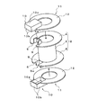
- FIG. 1A is an exploded perspective view of a bobbin and a lid, showing a winding component according to an embodiment of the present invention.
- FIG. 1B is a perspective view similar to FIG. 1A, showing a state where the winding portion is cut in the radial direction.
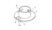
- FIG. 1C is a perspective view of the bobbin, similar to FIG. 1A.
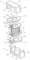
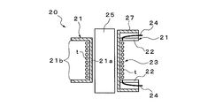
- FIG. 2 is an exploded perspective view of the winding component according to the embodiment of the present invention.
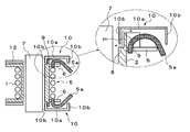
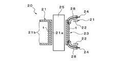
- FIG. 3A shows a winding component according to an embodiment of the present invention, and is an assembly completion drawing.
- 3B is a cross-sectional view taken along the line AA in FIG. 3A and a partially enlarged view.
- FIG. 3C is a cross-sectional view taken along the line AA of FIG.
- FIG. 4A is a schematic view showing a conventional method for insulating a lead wire of a winding component.
- FIG. 4B is a schematic diagram illustrating a conventional method for insulating a lead wire of a winding component.
- FIG. 4C is a schematic diagram illustrating a conventional method for insulating a lead wire of a winding component.
- FIGS. 1A to 3C show an embodiment of a winding member according to the present invention.
- This winding component 1 has flanges 4 at both ends in the axial direction of a cylindrical (tubular) winding part 3.
- the bobbin 2 is formed of an insulating member such as a synthetic resin.
- the notch part 6 which draws out the lead wire (end part) 5a of the coil 5 outward is formed in the collar part 4. As shown in FIG.
- the notch 6 is formed from the outer peripheral edge of the flange 4 toward the radially inner side, and is opened in a concave shape in plan view.
- a wall portion 9 surrounding the notch portion 6 is erected on the flange portion 4 so as to be directed outward in the axial direction.
- the wall portions 9 are erected along the closed edge portion of the notch portion 6, and are substantially half from the closed side of the edge portion of the notch portion 6 facing in the circumferential direction of the flange portion 4. It is erected at the position of the length dimension and is formed in a U shape in plan view.
- a thick part 8 is formed at the formation position of the notch part 6 formed in the flange part 4.
- This thick portion 8 is formed such that the thickness dimension A of the winding portion 3 is larger than the thickness dimension B of the other portion, and as shown in FIG. It is formed into a shape.
- the thick portion 8 secures a distance k between the wall portion 9 and the core 7 as shown in FIG. 1C.
- the coil 5 wound around the winding part 3 introduces the litz wire t into the winding part 3 from the outside of the bobbin 2 through, for example, a notch part 6 formed in the flange part 4 of the bobbin 2. Then, after being wound around the winding part 3, it is drawn out of the flange part 4 from the other notch part 6.
- a cap member 11 is disposed on the outer side of the flange 4 formed at both ends of the bobbin 2.
- the cap member 11 includes a lid body 10 that covers the wall portion 9 erected on the collar portion 4, and supports the lid body 10, and the core 7 is inserted therethrough and is in contact with the end surface of the collar portion 4.
- the donut disk-shaped support part 12 is comprised.
- the lid 10 is formed between the outer peripheral surface of the wall portion 9 and the core 7 at the side wall portion 10b covering the outer peripheral surface of the wall portion 9 and the axially outer end portion of the side wall portion 10b.
- the top plate 10a covers the opening of the wall 9.
- the side wall part 10b is formed in the square ring shape, and is formed integrally with the outer periphery of the top-plate part 10a formed in the rectangle in planar view.
- the E-shaped core 7 has a rectangular plate-like back portion 7a, substantially plate-like outer legs 7b standing on both ends in the longitudinal direction of the back portion 7a, and a central portion between the outer legs 7b. It is comprised by the provided column-shaped middle leg 7c.
- the middle leg 7c of the core 7 is inserted into the bobbin 2 and the support part 12 of the cap member 11, and the outer leg 7b and the back part 7a of the core 7 surround the outer periphery of the coil 5 and the end face of the flange part 4.
- a closed magnetic circuit in a letter shape (two E-shapes facing each other) is formed.
- the cap member 11 is disposed on the outer side of the flange portion 4 of the bobbin 2 and the cover body 10 is placed on the wall portion 9 erected on the flange portion 4.
- the top plate portion 10a of the lid 10 covers the opening 9a of the wall portion 9, and the side wall portion 10b comes into contact with the entire outer peripheral surface of the wall portion 9, so that the end of the side wall portion 10b is touched.
- the part comes into contact with the surface of the flange part 4 including the thick part 8 of the winding part 3.
- the middle legs 7 c of the pair of E-type cores 7 are inserted into the bobbin 2 and the support portion 12 of the cap member 11.
- the outer leg 7b and the back part 7a of the core 7 surround the outer periphery of the coil 5 and the end face of the collar part 4, and a Japanese character-like closed magnetic circuit is formed.
- the lead wire 5 a drawn out from the cutout portion 6 of the collar portion 4 is insulated from the core 7 by the lid body 10 placed on the wall portion 9.
- the wall portion 10b of the lid body 10 is inserted between the core 7 and the wall portion 9 by the thick portion 8 of the winding portion 3, and the wall
- a creepage distance m from the middle leg of the core 7 to the lead wire 5a is formed, and insulation between the middle leg of the core 7 and the lead wire 5a is ensured.
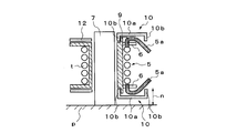
- the completed winding component 1 is attached to the housing p.
- the lead wire 5a drawn out from the notch portion 6 of the flange portion 4 is bent inward in the axial direction by the side wall portion 10b formed in a continuous annular shape of the lid body 10, A creepage distance n from the housing p to the lead wire 5a is formed.
- the wall portion 9 surrounding the notch portion 6 is outside the axial direction in the notch portion 6 that draws the lead wire 5a of the coil 5 formed in the flange portion 4 of the bobbin 2. Since the lid 10 is provided so as to stand toward the direction and covers the outer peripheral surface of the wall 9 and the opening 9a, the winding of the bobbin 2 is possible even when the litz wire t is used for the coil 5. After performing the winding work on the wire part 3, the cover 10 is put on the wall part 9, so that the above-mentioned winding work can be easily performed, and the product quality is improved by eliminating the winding defect. be able to.
- the thick portion 8 having a larger thickness than the other portions of the winding portion 3 is formed at the formation position of the notch portion 6 formed in the flange portion 4, so that the outer peripheral surface of the wall portion 9 and Since the lid body 10 including the side wall portion 10b covering the outer peripheral surface of the wall portion 9 and the top plate portion 10a covering the opening portion 9a of the wall portion 9 can be provided between the core 7 and the wall portion 7, The creepage distance of the lead wire 5a of the coil 5 from the core 7 can be ensured without integrally molding the cover 9 and the cover 9. As a result, insulation between the core 7 and the lead wire 5a of the coil 5 can be ensured.
- the thick part 8 is formed in a part of the winding part 3, an increase in the winding length of the coil 5 wound around the winding part 3 can be suppressed. As a result, it is possible to suppress the copper loss and the increase in the manufacturing cost accompanying the increase in the winding length of the coil 5.
- the lid 10 has an annular shape with a continuous side wall portion and a top plate portion is formed at the axially outer end portion of the side wall portion, the end of the coil drawn out from the notch portion is formed. The portion is bent inward in the axial direction by the side wall portion.
- the present invention is not limited to this.
- the thickness of the winding portion 3 is the same, and the hook portion 4 is formed to have an oval shape in cross-sectional view. It is possible to cope with the wall portion where the cutout portion 6 is formed protruding outward. Also in this case, as shown in FIG. 1C, a distance k can be secured between the wall portion 9 and the core 7.
- the pair of cores 7 has been described only when the E-type core 7 is used, the present invention is not limited to this, and the present invention can be applied by combining E-type and I-type ferrite cores.
- It can be used for choke coils and transformers that are wound around the outer periphery of the core mounted on electronic equipment.
Abstract
大電流に対応する径寸法の大きな電線を用いてコイルからの引出し線とコアとの絶縁を確保することができるとともに、当該電線の巻線作業を容易に行うことができる巻線部品を提供する。本発明は、コイル(5)の外周および鍔部(4)の端面を囲繞して閉磁路を形成するコア(7)を備えた巻線部品において、鍔部(4)にコイル(5)の端部(5a)を外方に引き出すための切欠部(6)が外周縁から径方向内方に向けて形成され、かつ切欠部(6)を囲繞する壁部(9)が上記軸線方向外方に向けて立設されるとともに、巻線部(3)の切欠部(6)の形成位置に肉厚寸法が他よりも大きく形成された肉厚部(8)が形成され、壁部(9)の外周面とコア(7)との間に壁部(9)の外周面を覆う側壁部(10b)と、側壁部(10b)の軸線方向外方端部に形成されて壁部(9)の開口部(9a)を覆う天板部(10a)とからなる蓋体(10)が設けられている。
Description
本発明は、コアの外周にコイルを巻回したチョークコイルやトランスなどとして、電子回路に使用される巻線部品に関するものである。
従来の巻線部品として、電気自動車や大型サーバー等に使用される電源トランスやDC-DCコンバータに用いられるトランスやチョークコイルなどがある。
一般的に、上記巻線部品を大電流で使用される場合、コイルを形成する線材に銅損を生じ、これによりフェライトコアの熱暴走や周辺材料の耐熱性に懸念を生じることにより、当該トランスの熱的成立を困難にするおそれが生じる。このため、例えば、コイルを構成する電線の径寸法を大きくすることにより、電気抵抗を軽減して、銅損が生じないようにしている。
ところで、コアの外周に電線を巻線する場合、図4に示すように、例えば、コア25がE型コアの場合、このコア25の中脚を絶縁材料からなるボビン21に挿入し、このボビン21の筒状の巻線部21aに、銅線などの電線tを巻回してコイル23を形成する。このボビン21は、鍔部21bに形成された切欠部22から引出し線24を当該鍔部の外方に引き出すため、コア25と電線tとの絶縁を確保する必要がある。また、巻線部品20が筐体に取り付けられる場合には、ボビン21に巻回されたコイル23から引き出された引出し線24と、当該筐体との絶縁も確保する必要がある。
このため、従来においては、図4Aに示すように、ボビン21の鍔部21bに形成された切欠部22と、コア25との間に壁部26を設けるとともに、引出し線24を当該壁部26から極力離して引き出す方法や、図4Bに示すように、ボビン21の鍔部21bに形成された切欠部22を樹脂27で覆う方法、さらに、図4Cに示すように、引出し線24に絶縁チューブ28を被せる方法などが提案されている。
しかしながら、巻線部品20が大電流で使われる場合、とくに、電流が10A~30A以上の大電量が流れる場合には、銅損を抑えるために電線を太くする必要がある。例えば、撚り本数の多いリッツ線を用いる場合、仕上げ径寸法が直径2~3mmになる。そのため、ボビン21の鍔部21bに設けられた切欠部22とコア25との間に壁部26を設け、かつ引出し線24を当該壁部26から極力離して引き出す図4Aに示す従来の方法では、引出し線24の曲げ半径が大きくなり、コア25と当該引出し線24との沿面距離を十分に取ることができないという問題がある。
また、ボビン21の鍔部21bに形成された切欠部22を樹脂27で覆う図4Bに示す従来の方法では、一般的な実装上の理由から、当該切欠部22を樹脂27で覆う際には大きさが制限されるため、太い電線を収めるスペースを十分に確保することができない。このため、巻線作業時に引出し線24が浮き上がったり、ボビン21から外れるなど、作業性や品質が低下するという問題がある。
そこで、鍔部21bに形成された切欠部22から引き出される引出し線24を治具などを用いて押さえ、巻線作業を行うことも考えられるが、一般的に切欠部22を樹脂27で覆った部分は狭く、当該治具が入るスペースを確保することが難しい。さらに、巻線部品20が筐体に直接設置される場合には、下側に引き出される引出し線24と当該筐体との絶縁距離が不足してしまうという問題もある。
さらに、コア25とコイル23との間に高い耐電圧が要求される場合、例えば、AC2000Vの耐電圧が要求される場合、通常、引出し線24とコア25との沿面距離は、数mm以上確保できるように設計・製造する。また、巻線部品20に安全規格が求められる場合には、引出し線24とコア25との間に大きな沿面距離を確保する必要がある。例えば、動作電圧400V時における各種規格の要求沿面距離は、下の表1に示す通りである。表1は、巻線部品の動作電圧400V時における安全規格を示す表である。

このように、コア25とコイル23との間に高い耐電圧が要求される巻線部品20においては、従来、図4Cに示すように、引出し線24に絶縁チューブ28を被せる方法が用いられていた。この従来の方法では、引出し線24に絶縁チューブ28を被せた状態で、ボビン21の鍔部21bに形成された切欠部22から当該引出し線24を引き出していた。
しかし、大電流の巻線部品20においては、電線t自体が太くなるため、当該電線tに絶縁チューブ28を被せる作業に手間が掛かるとともに、強化絶縁を満足する絶縁チューブ28は高価であるために、製造コストが嵩むという問題がある。
また、絶縁チューブ28自体も太くなり、この絶縁チューブ28をコイル23に巻き込むことによって、当該コイル23が巻き太りしてしまうとともに、切欠部22から引き出される引出し線24が曲げ難くなり、引き回しの自由度が制約されてしまうという問題もある。
本発明は、かかる事情に鑑みてなされたもので、大電流に対応する径寸法の大きな電線を用いてコイルからの引出し線とコアとの絶縁を確保することができるとともに、当該電線の巻線作業を容易に行うことができる巻線部品を提供することを課題とするものである。
上記課題を解決するために、請求項1に記載の発明は、筒状の巻線部の軸線方向両端に鍔部が形成されたボビンと、このボビンの上記巻線部に巻回されたコイルと、このコイルの外周および上記鍔部の端面を囲繞して閉磁路を形成するコアとを備えた巻線部品において、上記鍔部に、上記コイルの端部を外方に引き出すための切欠部が外周縁から径方向内方に向けて形成され、かつ上記切欠部を囲繞する壁部が上記軸線方向外方に向けて立設されるとともに、上記巻線部の上記切欠部の形成位置に、肉厚寸法が他の部分よりも大きく形成された肉厚部が形成され、上記壁部の外周面と上記コアとの間に、上記壁部の外周面を覆う側壁部と、この側壁部の上記軸線方向外方端部に形成されて上記壁部の開口部を覆う天板部とからなる蓋体が設けられていることを特徴とするものである。
また、請求項2に記載の発明は、請求項1に記載の発明において、上記蓋体は、上記側壁部が連続した環状をなして、当該側壁部の上記軸線方向外方端部に天板部が形成されていることを特徴とするものである。
請求項1~2に記載の本発明によれば、ボビンの鍔部に形成されたコイルの端部を引き出す切欠部に、この切欠部を囲繞する壁部が軸線方向外方に向けて立設されているとともに、当該壁部の外周面および開口部を覆う蓋体が設けられているため、上記コイルに径寸法の大きい電線を用いた場合でも、上記ボビンの上記巻線部への巻線作業を行った後に、上記蓋体を上記壁部に被せることにより、上記巻線作業を容易に行うことができるとともに、巻線不良などをなくし製品品質の向上を図ることができる。
また、上記巻線部の他の部分よりも肉厚寸法が大きい上記肉厚部が、上記鍔部に形成された上記切欠部の形成位置に形成されることにより、上記壁部の外周面と上記コアとの間に、当該壁部の外周面を覆う側壁部と、当該壁部の開口部を覆う天板部とからなる蓋体を設けることができるため、上記壁部と上記蓋体とを一体に成型することなく、上記コアから上記コイルの端部の沿面距離を確保することができる。この結果、上記コアと上記コイルの端部との絶縁を確保することができる。
そして、上記肉厚部を上記巻線部の一部分に形成するため、上記巻線部に巻回される上記コイルの巻線長の増加を抑えることができる。この結果、上記コイルの巻線長さが増すことに伴う銅損、および製造コストの増加を抑えることができる。
請求項2に記載の発明によれば、上記蓋体は、上記側壁部が連続した環状をなして、当該側壁部の上記軸線方向外方端部に天板部が形成されているため、上記切欠部から引き出された上記コイルの端部が、当該側壁部によって軸線方向内方に屈曲される。これにより、巻線部品を筐体などに取り付け場合に、当該筐体と上記引出し線との沿面距離を増大させることができる。この結果、上記筐体と上記引出し線との絶縁を確保することができる。
図1A~図3Cは、本発明に係る巻線部材の一実施形態を示すもので、この巻線部品1は、円筒状(筒状)の巻線部3の軸線方向両端に鍔部4が形成されたボビン2と、このボビン2の巻線部3に巻回されたコイル5と、このコイル5の外周および上記鍔部の端面を囲繞して閉磁路を形成するコア7とを備えて概略構成されている。
ここで、ボビン2は、絶縁性部材、例えば、合成樹脂などにより形成されている。そして、鍔部4には、コイル5の引出し線(端部)5aを外方に引き出す切欠部6が形成されている。この切欠部6は、鍔部4の外周縁から径方向内方に向けて形成され、平面視において凹状に開口されている。
また、鍔部4には、切欠部6を囲繞する壁部9が軸線方向外方に向けて立設されている。この壁部9は、切欠部6の閉塞側の縁部に沿って立設されているとともに、鍔部4の円周方向において対向する切欠部6の縁部の上記閉塞側から各々略半分の長さ寸法の位置に立設され、平面視においてコ字状に形成されている。
そして、ボビン2の巻線部3には、鍔部4に形成された切欠部6の形成位置に肉厚部8が形成されている。この肉厚部8は、巻線部3の肉厚寸法Aが、他の部分の肉厚寸法Bより大きく形成され、図1Aに示すように、巻線部3の径方向の断面視において卵形に形成されている。この肉厚部8により、図1Cに示すように、壁部9とコア7との間に距離kが確保される。
さらに、巻線部3に巻回されるコイル5は、例えば、ボビン2の鍔部4に開口して形成された切欠部6を通じて、リッツ線tをボビン2の外部から巻線部3に導入して、巻線部3に巻回した後、もう一方の切欠部6から当該鍔部4の外方に引き出されている。
また、ボビン2の両端部に形成された鍔部4の外方側に、キャップ部材11が配設されている。このキャップ部材11は、鍔部4に立設されている壁部9を覆う蓋体10と、この蓋体10を支持するとともに、コア7が挿通され、かつ鍔部4の端面に当接されるドーナツ円板状の支持部12から構成されている。
そして、蓋体10は、壁部9の外周面とコア7との間に、当該壁部9の外周面を覆う側壁部10bと、この側壁部10bの上記軸線方向外方端部に形成されて、壁部9の開口部を覆う天板部10aとから構成されている。また、側壁部10bは角環状に形成されて、平面視において長方形に形成された天板部10aの外周縁と一体に形成されている。
さらに、コイル5の外周および鍔部4の端面を囲繞して閉磁路を形成するコア7は、一対のE型のフェライトコアが用いられている。このE型のコア7は、長方形板状の背部7aと、この背部7aの長手方向の両端部に各々立設された略板状の外脚7bと、これら外脚7b間の中央部に立設された円柱状の中脚7cにより構成されている。
そして、コア7の中脚7cをボビン2およびキャップ部材11の支持部12に挿入されているとともに、コア7の外脚7bおよび背部7aにより、コイル5の外周および鍔部4の端面が囲繞され、日字状(対向する2個のE字状)の閉磁路が形成されている。
上記構成からなる巻線部品1を組み立てる際には、まず、リッツ線tの片端を固定した後、ボビン2の粒部4に開口して形成された切欠部6を通じて、リッツ線tを巻線部3に導入する。そして、リッツ線tを巻線部3に巻回した後、もう一方の切欠部6から当該鍔部4の外方に引き出す。
次に、ボビン2の鍔部4の外方側にキャップ部材11を配設するとともに、鍔部4に立設された壁部9に蓋体10を被せる。その際に、蓋体10の天板部10aが、壁部9の開口部9aを覆うとともに、側壁部10bが壁部9の外周面の全面を覆うに当接され、当該側壁部10bの端部が巻線部3の肉厚部8を含む鍔部4の表面に当接される。
そして、一対のE型のコア7の中脚7cをボビン2およびキャップ部材11の支持部12に挿入する。これにより、コア7の外脚7bおよび背部7aが、コイル5の外周および鍔部4の端面を囲繞して、日字状の閉磁路が形成される。その際、壁部9に被せた蓋体10により、鍔部4の切欠部6から引き出された引出し線5aは、コア7から絶縁させる。
なお、図3Bの部分拡大断面図に示すように、巻線部3の肉厚部8により、コア7と壁部9との間に、蓋体10の側壁部10bを挿入して、当該壁部9の開口部9aを天板部10aにより覆うことにより、コア7の中脚から引出し線5aまでの沿面距離mが形成されて、コア7の中脚と引出し線5aとの絶縁が確保される。
さらに、完成した巻線部品1を筐体pに取り付ける。その際、図3Cに示すように鍔部4の切欠部6から引き出された引出し線5aが、蓋体10の連続した環状に形成された側壁部10bによって、軸線方向内側に向かって屈曲され、筐体pから引出し線5aまでの沿面距離nが形成される。
以上の構成からなる巻線部品1によれば、ボビン2の鍔部4に形成されたコイル5の引出し線5aを引き出す切欠部6に、この切欠部6を囲繞する壁部9が軸線方向外方に向けて立設されているとともに、この壁部9の外周面および開口部9aを覆う蓋体10が設けられているため、コイル5にリッツ線tを用いた場合でも、ボビン2の巻線部3への巻線作業を行った後に、蓋体10を壁部9に被せることにより、上記巻線作業を容易に行うことができるとともに、巻線不良などをなくし製品品質の向上を図ることができる。
また、巻線部3の他の部分よりも肉厚寸法が大きい肉厚部8が、鍔部4に形成された切欠部6の形成位置に形成されることにより、壁部9の外周面とコア7との間に、当該壁部9の外周面を覆う側壁部10bと、当該壁部9の開口部9aを覆う天板部10aとからなる蓋体10を設けることができるため、壁部9と蓋体10とを一体に成型することなく、コア7からコイル5の引出し線5aの沿面距離を確保することができる。この結果、コア7とコイル5の引出し線5aとの絶縁を確保することができる。
そして、肉厚部8が巻線部3の一部分に形成されているため、巻線部3に巻回されるコイル5の巻線長の増加を抑えることができる。この結果、コイル5の巻線長さが増すことに伴う銅損、および製造コストの増加を抑えることができる。
さらに、蓋体10は、側壁部が連続した環状をなして、当該側壁部の上記軸線方向外方端部に天板部が形成されているため、上記切欠部から引き出された上記コイルの端部が、当該側壁部によって軸線方向内方に屈曲される。これにより、巻線部品を筐体などに取り付け場合に、当該筐体と上記引出し線との沿面距離を増大させることができる。この結果、上記筐体と上記引出し線との絶縁を確保することができる。
なお、上記実施の形態においては、肉厚部8として、鍔部4に形成された切欠部6の形成位置の巻線部3の肉厚寸法を他の部分の肉厚寸法より大きく形成した場合のみ説明したが、本発明はこれに限定されるものでなく、例えば、巻線部3の肉厚寸法を同じに形成し、断面視において卵形になるように、鍔部4に形成された切欠部6の形成位置の壁部を外方に突出させても対応可能である。この場合も、図1Cに示すように、壁部9とコア7との間に距離kを確保することができる。
また、上記実施形態においては、ボビン2の巻線部3に巻回してコイル5を構成する電線tとして、リッツ線tを用いる場合のみ説明したが、本発明はこれに限定されるものでなく、チョークコイルおよびトランスの仕様に基づいて、様々な線種の電線を用いることが可能である。
さらに、一対のコア7をE型のコア7を用いる場合のみ説明したが、本発明はこれに限定されるものではなく、E型とI型のフェライトコアを組み合わせても対応可能である。
電子機器などに実装されるコアの外周にコイルを巻回したチョークコイルやトランスなどに利用することができる。
1 巻線部品
2 ボビン
3 巻線部
4 鍔部
5 コイル
5a 引出し線(端部)
6 切欠部
7 コア(コア)
8 肉厚部
9 壁部
9a 開口部
10 蓋体
10a 天板部
10b 側壁部
11 キャップ部材
12 支持部
t リッツ線(電線)
2 ボビン
3 巻線部
4 鍔部
5 コイル
5a 引出し線(端部)
6 切欠部
7 コア(コア)
8 肉厚部
9 壁部
9a 開口部
10 蓋体
10a 天板部
10b 側壁部
11 キャップ部材
12 支持部
t リッツ線(電線)
Claims (2)
- 筒状の巻線部の軸線方向両端に鍔部が形成されたボビンと、このボビンの上記巻線部に巻回されたコイルと、このコイルの外周および上記鍔部の端面を囲繞して閉磁路を形成するコアとを備えた巻線部品において、
上記鍔部に、上記コイルの端部を外方に引き出すための切欠部が外周縁から径方向内方に向けて形成され、かつ上記切欠部を囲繞する壁部が上記軸線方向外方に向けて立設されるとともに、上記巻線部の上記切欠部の形成位置に、肉厚寸法が他の部分よりも大きく形成された肉厚部が形成され、上記壁部の外周面と上記コアとの間に、上記壁部の外周面を覆う側壁部と、この側壁部の上記軸線方向外方端部に形成されて上記壁部の開口部を覆う天板部とからなる蓋体が設けられていることを特徴とする巻線部品。 - 上記蓋体は、上記側壁部が連続した環状をなして、当該側壁部の上記軸線方向外方端部に天板部が形成されていることを特徴とする請求項1に記載の巻線部品。
Priority Applications (2)
| Application Number | Priority Date | Filing Date | Title |
|---|---|---|---|
| EP14774813.1A EP2980814B1 (en) | 2013-03-28 | 2014-01-16 | Winding component |
| US14/771,711 US9672972B2 (en) | 2013-03-28 | 2014-01-16 | Winding component |
Applications Claiming Priority (2)
| Application Number | Priority Date | Filing Date | Title |
|---|---|---|---|
| JP2013069327A JP6152615B2 (ja) | 2013-03-28 | 2013-03-28 | 巻線部品 |
| JP2013-069327 | 2013-03-28 |
Publications (1)
| Publication Number | Publication Date |
|---|---|
| WO2014155905A1 true WO2014155905A1 (ja) | 2014-10-02 |
Family
ID=51622932
Family Applications (1)
| Application Number | Title | Priority Date | Filing Date |
|---|---|---|---|
| PCT/JP2014/000190 WO2014155905A1 (ja) | 2013-03-28 | 2014-01-16 | 巻線部品 |
Country Status (4)
| Country | Link |
|---|---|
| US (1) | US9672972B2 (ja) |
| EP (1) | EP2980814B1 (ja) |
| JP (1) | JP6152615B2 (ja) |
| WO (1) | WO2014155905A1 (ja) |
Families Citing this family (9)
| Publication number | Priority date | Publication date | Assignee | Title |
|---|---|---|---|---|
| CN108140629A (zh) | 2015-08-07 | 2018-06-08 | 韦沙戴尔电子有限公司 | 模制体和用于高电压应用的具有模制体的电气装置 |
| US9570228B1 (en) | 2015-08-21 | 2017-02-14 | Chicony Power Technology Co., Ltd. | Transfomer structure |
| CN110114846B (zh) | 2016-12-20 | 2022-03-29 | Lg伊诺特有限公司 | 磁芯、线圈组件以及包括线圈组件的电子组件 |
| JP6930177B2 (ja) * | 2017-03-30 | 2021-09-01 | スミダコーポレーション株式会社 | トランス及びトランスの製造方法 |
| DE102017121908B4 (de) | 2017-09-21 | 2023-12-07 | Tdk Electronics Ag | Elektrisches Bauelement mit Litzenkontakt und Verfahren zur Herstellung eines Litzenkontakts |
| DE102017121924B3 (de) * | 2017-09-21 | 2019-02-21 | Tdk Electronics Ag | Elektrisches Bauelement mit Anschlussbereich und Verfahren zur Herstellung eines Anschlussbereichs |
| JP7268289B2 (ja) * | 2018-03-20 | 2023-05-08 | スミダコーポレーション株式会社 | コイル部品 |
| JP1698759S (ja) * | 2021-06-08 | 2021-11-01 | ||
| JP1719210S (ja) * | 2021-09-01 | 2022-07-07 | 電動機用回転子 |
Citations (4)
| Publication number | Priority date | Publication date | Assignee | Title |
|---|---|---|---|---|
| JPS5529228Y2 (ja) * | 1976-02-13 | 1980-07-11 | ||
| JPS633130Y2 (ja) * | 1981-12-25 | 1988-01-26 | ||
| JPH0662520U (ja) * | 1993-02-04 | 1994-09-02 | 田淵電機株式会社 | トランスの電線固定構造 |
| US20020175798A1 (en) * | 2001-05-22 | 2002-11-28 | Dennis Sigl | Welding power supply transformer |
Family Cites Families (30)
| Publication number | Priority date | Publication date | Assignee | Title |
|---|---|---|---|---|
| US1647372A (en) * | 1924-10-18 | 1927-11-01 | Jackson H Pressley | Long-wave or intermediate-frequency transformer |
| US3213397A (en) * | 1961-04-28 | 1965-10-19 | Gen Electric | Electrical winding spool for electrical apparatus |
| US3259864A (en) * | 1963-06-26 | 1966-07-05 | Bomax Inc | Coil construction and means for locking the leads thereon |
| US3371302A (en) * | 1965-04-23 | 1968-02-27 | Dynamic Instr Corp | Power supply and improved transformer structure therefor |
| US3363210A (en) * | 1965-07-06 | 1968-01-09 | Heinemann Electric Co | Coil and spool and an improved method of making a coil |
| US3461413A (en) * | 1966-11-10 | 1969-08-12 | Teletype Corp | Shielded electrical inductor component |
| GB1209401A (en) * | 1968-03-09 | 1970-10-21 | Bsr Ltd | Coil windings for electrical equipment |
| GB1330797A (en) * | 1972-01-19 | 1973-09-19 | Pye Ltd | Bobbins for electrical coils |
| US3800172A (en) * | 1972-11-10 | 1974-03-26 | Oster J Mfg Co | Hair clipper having blade illumination and field wire strain relief |
| US4010435A (en) * | 1975-06-04 | 1977-03-01 | Katumi Shigehara | Terminals for coil bobbin |
| US4347493A (en) * | 1977-02-28 | 1982-08-31 | Emhart Industries, Inc. | Coil assembly |
| JPS5529228A (en) | 1978-08-17 | 1980-03-01 | Mitsubishi Electric Corp | Switching regulator for pcm device |
| US4363014A (en) * | 1981-05-06 | 1982-12-07 | Emerson Electric Co. | Snap-on cover for bobbin-wound coil assembly |
| US4394637A (en) * | 1981-07-10 | 1983-07-19 | U.S. Philips Corporation | Wound bobbin coil apparatus |
| US4626813A (en) * | 1984-04-04 | 1986-12-02 | Omron Tateisi Electronics Co. | Electromagnetic drive and polarized relay |
| US4520288A (en) * | 1984-04-05 | 1985-05-28 | Briggs & Stratton Corp. | Ignition magneto having an improved primary winding construction |
| US4546340A (en) * | 1984-07-30 | 1985-10-08 | The Singer Company | Electrical coil assembly |
| US4672348A (en) * | 1985-02-19 | 1987-06-09 | Eaton Corporation | Electrical coil assembly and terminal therefor |
| JPS633130A (ja) | 1986-10-27 | 1988-01-08 | Sanyo Electric Co Ltd | 芯上下式石油スト−ブ |
| US4890085A (en) * | 1987-10-21 | 1989-12-26 | Tdk Electronic Co., Ltd. | Terminal fitted bobbin |
| US4880182A (en) * | 1988-03-25 | 1989-11-14 | Stanley Gelfman | Cable reel |
| US4945328A (en) * | 1988-10-31 | 1990-07-31 | Furnas Electric Company | Electrical contactor |
| JPH0297844U (ja) * | 1989-01-20 | 1990-08-03 | ||
| US5270604A (en) * | 1992-05-21 | 1993-12-14 | Ford Motor Company | Tandem field alternator having an improved coil and slip ring connection and method of making the same |
| JP3184323B2 (ja) | 1992-08-05 | 2001-07-09 | 東神電気株式会社 | 架空電線引留具とその製造方法 |
| US5424691A (en) * | 1994-02-03 | 1995-06-13 | Sadinsky; Samuel | Apparatus and method for electronically controlled admittance matching network |
| DE19541447A1 (de) * | 1995-11-07 | 1997-05-15 | Peter Weiner | Spulenkörper |
| US5999079A (en) * | 1996-09-30 | 1999-12-07 | Siemens Aktiengesellschaft | Magnet coil with radial terminal pins and the method for manufacturing the coil |
| JP2003332120A (ja) * | 2002-05-10 | 2003-11-21 | Minebea Co Ltd | ボビン構造及びそれを用いたトランス及びインダクタ |
| US7026739B2 (en) * | 2003-05-23 | 2006-04-11 | Honda Motor Co., Ltd | Stator and insulating bobbin and a manufacturing method of the stator |
-
2013
- 2013-03-28 JP JP2013069327A patent/JP6152615B2/ja active Active
-
2014
- 2014-01-16 WO PCT/JP2014/000190 patent/WO2014155905A1/ja active Application Filing
- 2014-01-16 US US14/771,711 patent/US9672972B2/en active Active
- 2014-01-16 EP EP14774813.1A patent/EP2980814B1/en not_active Not-in-force
Patent Citations (4)
| Publication number | Priority date | Publication date | Assignee | Title |
|---|---|---|---|---|
| JPS5529228Y2 (ja) * | 1976-02-13 | 1980-07-11 | ||
| JPS633130Y2 (ja) * | 1981-12-25 | 1988-01-26 | ||
| JPH0662520U (ja) * | 1993-02-04 | 1994-09-02 | 田淵電機株式会社 | トランスの電線固定構造 |
| US20020175798A1 (en) * | 2001-05-22 | 2002-11-28 | Dennis Sigl | Welding power supply transformer |
Also Published As
| Publication number | Publication date |
|---|---|
| JP2014192498A (ja) | 2014-10-06 |
| US20150380156A1 (en) | 2015-12-31 |
| US9672972B2 (en) | 2017-06-06 |
| JP6152615B2 (ja) | 2017-06-28 |
| EP2980814A4 (en) | 2016-12-14 |
| EP2980814B1 (en) | 2017-10-18 |
| EP2980814A1 (en) | 2016-02-03 |
Similar Documents
| Publication | Publication Date | Title |
|---|---|---|
| JP6152615B2 (ja) | 巻線部品 | |
| JP6079225B2 (ja) | トランス | |
| JP6497521B2 (ja) | トランス | |
| EP3109873B1 (en) | Inductor coil and electromagnetic component | |
| JP5861805B2 (ja) | トランス、電源装置およびトランスの製造方法 | |
| US20220130602A1 (en) | Transformer And Method For Manufacturing Transformer | |
| JP2007142339A (ja) | 耐雷強化型低圧用絶縁変圧器 | |
| JP2019134126A (ja) | 静止誘導機器 | |
| JP5177231B2 (ja) | アーク溶接機に用いる変圧器およびアーク溶接機に用いる変圧器の組み立て方法 | |
| JP3946065B2 (ja) | トランス | |
| JPS63293804A (ja) | マイクロ波オーブン用変圧器 | |
| JP2010021479A (ja) | トランス | |
| JP2008147358A (ja) | 絶縁トランス | |
| JP6451229B2 (ja) | トランス | |
| US20160111206A1 (en) | Transformer | |
| CN107017084B (zh) | 线圈装置 | |
| JP2010263077A (ja) | リアクトル | |
| JP6210403B2 (ja) | 巻線部品 | |
| EP2479764B1 (en) | Resin molded coil and molded transformer using the same | |
| JP2016100465A (ja) | チョークコイル | |
| JP7308093B2 (ja) | 変圧器及びボビン | |
| WO2014162684A1 (ja) | 電源トランス | |
| US20170194828A1 (en) | Electric Engine Stator, Electric Engine, and Electric Engine Stator Coil Insulation Process | |
| US1477396A (en) | Stationary induction apparatus | |
| JP2006128179A (ja) | 静止誘導機器コイル |
Legal Events
| Date | Code | Title | Description |
|---|---|---|---|
| 121 | Ep: the epo has been informed by wipo that ep was designated in this application |
Ref document number: 14774813 Country of ref document: EP Kind code of ref document: A1 |
|
| WWE | Wipo information: entry into national phase |
Ref document number: 14771711 Country of ref document: US |
|
| REEP | Request for entry into the european phase |
Ref document number: 2014774813 Country of ref document: EP |
|
| WWE | Wipo information: entry into national phase |
Ref document number: 2014774813 Country of ref document: EP |
|
| NENP | Non-entry into the national phase |
Ref country code: DE |