WO2014155905A1 - Élément d'enroulement - Google Patents
Élément d'enroulement Download PDFInfo
- Publication number
- WO2014155905A1 WO2014155905A1 PCT/JP2014/000190 JP2014000190W WO2014155905A1 WO 2014155905 A1 WO2014155905 A1 WO 2014155905A1 JP 2014000190 W JP2014000190 W JP 2014000190W WO 2014155905 A1 WO2014155905 A1 WO 2014155905A1
- Authority
- WO
- WIPO (PCT)
- Prior art keywords
- winding
- coil
- core
- wall portion
- bobbin
- Prior art date
Links
Images


Classifications
-
- H—ELECTRICITY
- H01—ELECTRIC ELEMENTS
- H01F—MAGNETS; INDUCTANCES; TRANSFORMERS; SELECTION OF MATERIALS FOR THEIR MAGNETIC PROPERTIES
- H01F27/00—Details of transformers or inductances, in general
- H01F27/28—Coils; Windings; Conductive connections
- H01F27/32—Insulating of coils, windings, or parts thereof
- H01F27/324—Insulation between coil and core, between different winding sections, around the coil; Other insulation structures
- H01F27/325—Coil bobbins
-
- H—ELECTRICITY
- H01—ELECTRIC ELEMENTS
- H01F—MAGNETS; INDUCTANCES; TRANSFORMERS; SELECTION OF MATERIALS FOR THEIR MAGNETIC PROPERTIES
- H01F27/00—Details of transformers or inductances, in general
- H01F27/28—Coils; Windings; Conductive connections
- H01F27/2823—Wires
- H01F27/2828—Construction of conductive connections, of leads
-
- H—ELECTRICITY
- H01—ELECTRIC ELEMENTS
- H01F—MAGNETS; INDUCTANCES; TRANSFORMERS; SELECTION OF MATERIALS FOR THEIR MAGNETIC PROPERTIES
- H01F27/00—Details of transformers or inductances, in general
- H01F27/28—Coils; Windings; Conductive connections
- H01F27/32—Insulating of coils, windings, or parts thereof
- H01F27/324—Insulation between coil and core, between different winding sections, around the coil; Other insulation structures
-
- H—ELECTRICITY
- H01—ELECTRIC ELEMENTS
- H01F—MAGNETS; INDUCTANCES; TRANSFORMERS; SELECTION OF MATERIALS FOR THEIR MAGNETIC PROPERTIES
- H01F27/00—Details of transformers or inductances, in general
- H01F27/28—Coils; Windings; Conductive connections
- H01F27/29—Terminals; Tapping arrangements for signal inductances
Definitions
- the present invention relates to a winding component used in an electronic circuit, such as a choke coil or a transformer in which a coil is wound around the outer periphery of a core.
- Conventional winding parts include power transformers used for electric vehicles and large servers, transformers used for DC-DC converters, and choke coils.
- the middle leg of the core 25 is inserted into a bobbin 21 made of an insulating material.
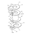
- the coil 23 is formed by winding an electric wire t such as a copper wire around the 21 cylindrical winding portion 21a. Since this bobbin 21 pulls out the lead wire 24 from the notch part 22 formed in the collar part 21b to the outside of the collar part, it is necessary to ensure insulation between the core 25 and the electric wire t. Further, when the winding component 20 is attached to the casing, it is necessary to ensure insulation between the lead wire 24 drawn from the coil 23 wound around the bobbin 21 and the casing.
- a wall portion 26 is provided between the core 25 and the cutout portion 22 formed in the flange portion 21b of the bobbin 21, and the lead wire 24 is connected to the wall portion 26.
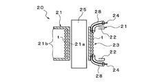
- 4B a method of covering the notch 22 formed on the flange 21b of the bobbin 21 with a resin 27 as shown in FIG. 4B, and an insulating tube connected to the lead wire 24 as shown in FIG. 4C. A method of covering 28 is proposed.
- the winding component 20 when the winding component 20 is used with a large current, particularly when a large electric current of 10 A to 30 A or more flows, it is necessary to increase the thickness of the wire in order to suppress copper loss.
- the finished diameter is 2 to 3 mm. Therefore, in the conventional method shown in FIG. 4A, a wall portion 26 is provided between the notch portion 22 provided in the flange portion 21b of the bobbin 21 and the core 25, and the lead wire 24 is pulled away from the wall portion 26 as much as possible. There is a problem that the bending radius of the lead wire 24 becomes large, and the creepage distance between the core 25 and the lead wire 24 cannot be sufficiently taken.
- the creepage distance between the lead wire 24 and the core 25 is usually secured to several mm or more. Design and manufacture as possible.
- a safety standard is required for the winding component 20
- Table 1 is a table showing safety standards when the operating voltage of the winding component is 400V.
- a method of covering the lead wire 24 with the insulating tube 28 is conventionally used as shown in FIG. 4C. It was. In this conventional method, the lead wire 24 is drawn out from the notch portion 22 formed in the flange portion 21b of the bobbin 21 in a state where the lead wire 24 is covered with the insulating tube 28.
- the insulating tube 28 itself becomes thick, and when the insulating tube 28 is wound around the coil 23, the coil 23 is wound and thickened, and the lead wire 24 drawn out from the notch 22 becomes difficult to bend, so that it can be freely routed. There is also a problem that the degree is constrained.
- the present invention has been made in view of such circumstances, and it is possible to secure insulation between the lead wire from the coil and the core using a large-diameter electric wire corresponding to a large current, and winding of the electric wire. It is an object of the present invention to provide a winding component that can be easily operated.
- the invention according to claim 1 is a bobbin in which flanges are formed at both ends in the axial direction of a cylindrical winding part, and a coil wound around the winding part of the bobbin. And a core that surrounds the outer periphery of the coil and the end face of the flange portion to form a closed magnetic circuit, and the notch portion for pulling out the end portion of the coil outward in the flange portion Is formed radially outward from the outer peripheral edge, and a wall portion surrounding the cutout portion is erected outward in the axial direction, and at the position where the cutout portion of the winding portion is formed.
- a wall portion covering the outer peripheral surface of the wall portion between the outer peripheral surface of the wall portion and the core, and a side wall portion formed between the outer peripheral surface of the wall portion and the core.
- a lid formed by a top plate portion that is formed at the outer end in the axial direction and covers the opening of the wall portion. And it is characterized in that it is.
- the lid body has an annular shape in which the side wall portion is continuous, and a top plate at the axially outer end portion of the side wall portion. A portion is formed.
- the wall portion surrounding the notch portion is erected outward in the axial direction at the notch portion for pulling out the end portion of the coil formed on the flange portion of the bobbin.
- a lid that covers the outer peripheral surface and the opening of the wall portion is provided, even when an electric wire having a large diameter is used for the coil, the bobbin is wound around the winding portion.
- the thick portion having a larger wall thickness than the other portions of the winding portion is formed at the formation position of the notch portion formed in the flange portion, so that the outer peripheral surface of the wall portion is Between the core, a lid body including a side wall portion covering the outer peripheral surface of the wall portion and a top plate portion covering the opening portion of the wall portion can be provided, and thus the wall portion and the lid body The creeping distance from the core to the end of the coil can be ensured without integrally molding the coil. As a result, insulation between the core and the end of the coil can be ensured.
- the said thick part is formed in a part of said winding part, the increase in the winding length of the said coil wound by the said winding part can be suppressed. As a result, it is possible to suppress an increase in copper loss and manufacturing cost associated with an increase in the winding length of the coil.
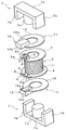
- FIG. 1A is an exploded perspective view of a bobbin and a lid, showing a winding component according to an embodiment of the present invention.
- FIG. 1B is a perspective view similar to FIG. 1A, showing a state where the winding portion is cut in the radial direction.
- FIG. 1C is a perspective view of the bobbin, similar to FIG. 1A.
- FIG. 2 is an exploded perspective view of the winding component according to the embodiment of the present invention.
- FIG. 3A shows a winding component according to an embodiment of the present invention, and is an assembly completion drawing.
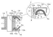
- 3B is a cross-sectional view taken along the line AA in FIG. 3A and a partially enlarged view.
- FIG. 3C is a cross-sectional view taken along the line AA of FIG.
- FIG. 4A is a schematic view showing a conventional method for insulating a lead wire of a winding component.
- FIG. 4B is a schematic diagram illustrating a conventional method for insulating a lead wire of a winding component.
- FIG. 4C is a schematic diagram illustrating a conventional method for insulating a lead wire of a winding component.
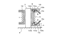
- FIGS. 1A to 3C show an embodiment of a winding member according to the present invention.
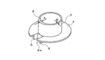
- This winding component 1 has flanges 4 at both ends in the axial direction of a cylindrical (tubular) winding part 3.
- the bobbin 2 is formed of an insulating member such as a synthetic resin.
- the notch part 6 which draws out the lead wire (end part) 5a of the coil 5 outward is formed in the collar part 4. As shown in FIG.
- the notch 6 is formed from the outer peripheral edge of the flange 4 toward the radially inner side, and is opened in a concave shape in plan view.
- a wall portion 9 surrounding the notch portion 6 is erected on the flange portion 4 so as to be directed outward in the axial direction.
- the wall portions 9 are erected along the closed edge portion of the notch portion 6, and are substantially half from the closed side of the edge portion of the notch portion 6 facing in the circumferential direction of the flange portion 4. It is erected at the position of the length dimension and is formed in a U shape in plan view.
- a thick part 8 is formed at the formation position of the notch part 6 formed in the flange part 4.
- This thick portion 8 is formed such that the thickness dimension A of the winding portion 3 is larger than the thickness dimension B of the other portion, and as shown in FIG. It is formed into a shape.
- the thick portion 8 secures a distance k between the wall portion 9 and the core 7 as shown in FIG. 1C.
- the coil 5 wound around the winding part 3 introduces the litz wire t into the winding part 3 from the outside of the bobbin 2 through, for example, a notch part 6 formed in the flange part 4 of the bobbin 2. Then, after being wound around the winding part 3, it is drawn out of the flange part 4 from the other notch part 6.
- a cap member 11 is disposed on the outer side of the flange 4 formed at both ends of the bobbin 2.
- the cap member 11 includes a lid body 10 that covers the wall portion 9 erected on the collar portion 4, and supports the lid body 10, and the core 7 is inserted therethrough and is in contact with the end surface of the collar portion 4.
- the donut disk-shaped support part 12 is comprised.
- the lid 10 is formed between the outer peripheral surface of the wall portion 9 and the core 7 at the side wall portion 10b covering the outer peripheral surface of the wall portion 9 and the axially outer end portion of the side wall portion 10b.
- the top plate 10a covers the opening of the wall 9.
- the side wall part 10b is formed in the square ring shape, and is formed integrally with the outer periphery of the top-plate part 10a formed in the rectangle in planar view.
- the E-shaped core 7 has a rectangular plate-like back portion 7a, substantially plate-like outer legs 7b standing on both ends in the longitudinal direction of the back portion 7a, and a central portion between the outer legs 7b. It is comprised by the provided column-shaped middle leg 7c.
- the middle leg 7c of the core 7 is inserted into the bobbin 2 and the support part 12 of the cap member 11, and the outer leg 7b and the back part 7a of the core 7 surround the outer periphery of the coil 5 and the end face of the flange part 4.
- a closed magnetic circuit in a letter shape (two E-shapes facing each other) is formed.
- the cap member 11 is disposed on the outer side of the flange portion 4 of the bobbin 2 and the cover body 10 is placed on the wall portion 9 erected on the flange portion 4.
- the top plate portion 10a of the lid 10 covers the opening 9a of the wall portion 9, and the side wall portion 10b comes into contact with the entire outer peripheral surface of the wall portion 9, so that the end of the side wall portion 10b is touched.
- the part comes into contact with the surface of the flange part 4 including the thick part 8 of the winding part 3.
- the middle legs 7 c of the pair of E-type cores 7 are inserted into the bobbin 2 and the support portion 12 of the cap member 11.
- the outer leg 7b and the back part 7a of the core 7 surround the outer periphery of the coil 5 and the end face of the collar part 4, and a Japanese character-like closed magnetic circuit is formed.
- the lead wire 5 a drawn out from the cutout portion 6 of the collar portion 4 is insulated from the core 7 by the lid body 10 placed on the wall portion 9.
- the wall portion 10b of the lid body 10 is inserted between the core 7 and the wall portion 9 by the thick portion 8 of the winding portion 3, and the wall
- a creepage distance m from the middle leg of the core 7 to the lead wire 5a is formed, and insulation between the middle leg of the core 7 and the lead wire 5a is ensured.
- the completed winding component 1 is attached to the housing p.
- the lead wire 5a drawn out from the notch portion 6 of the flange portion 4 is bent inward in the axial direction by the side wall portion 10b formed in a continuous annular shape of the lid body 10, A creepage distance n from the housing p to the lead wire 5a is formed.
- the wall portion 9 surrounding the notch portion 6 is outside the axial direction in the notch portion 6 that draws the lead wire 5a of the coil 5 formed in the flange portion 4 of the bobbin 2. Since the lid 10 is provided so as to stand toward the direction and covers the outer peripheral surface of the wall 9 and the opening 9a, the winding of the bobbin 2 is possible even when the litz wire t is used for the coil 5. After performing the winding work on the wire part 3, the cover 10 is put on the wall part 9, so that the above-mentioned winding work can be easily performed, and the product quality is improved by eliminating the winding defect. be able to.
- the thick portion 8 having a larger thickness than the other portions of the winding portion 3 is formed at the formation position of the notch portion 6 formed in the flange portion 4, so that the outer peripheral surface of the wall portion 9 and Since the lid body 10 including the side wall portion 10b covering the outer peripheral surface of the wall portion 9 and the top plate portion 10a covering the opening portion 9a of the wall portion 9 can be provided between the core 7 and the wall portion 7, The creepage distance of the lead wire 5a of the coil 5 from the core 7 can be ensured without integrally molding the cover 9 and the cover 9. As a result, insulation between the core 7 and the lead wire 5a of the coil 5 can be ensured.
- the thick part 8 is formed in a part of the winding part 3, an increase in the winding length of the coil 5 wound around the winding part 3 can be suppressed. As a result, it is possible to suppress the copper loss and the increase in the manufacturing cost accompanying the increase in the winding length of the coil 5.
- the lid 10 has an annular shape with a continuous side wall portion and a top plate portion is formed at the axially outer end portion of the side wall portion, the end of the coil drawn out from the notch portion is formed. The portion is bent inward in the axial direction by the side wall portion.
- the present invention is not limited to this.
- the thickness of the winding portion 3 is the same, and the hook portion 4 is formed to have an oval shape in cross-sectional view. It is possible to cope with the wall portion where the cutout portion 6 is formed protruding outward. Also in this case, as shown in FIG. 1C, a distance k can be secured between the wall portion 9 and the core 7.
- the pair of cores 7 has been described only when the E-type core 7 is used, the present invention is not limited to this, and the present invention can be applied by combining E-type and I-type ferrite cores.
- It can be used for choke coils and transformers that are wound around the outer periphery of the core mounted on electronic equipment.
Landscapes
- Engineering & Computer Science (AREA)
- Power Engineering (AREA)
- Insulating Of Coils (AREA)
Abstract
L'invention porte sur un élément d'enroulement, lequel élément fait en sorte que, à l'aide d'un fil électrique de grand diamètre qui peut acheminer de forts courants, un noyau et un fil conducteur à partir d'une bobine sont isolés l'un vis-à-vis de l'autre et le fil électrique est facile à enrouler. A cet effet, la présente invention porte sur un élément d'enroulement, lequel élément comporte un noyau (7) qui entoure une bobine (5) et des surfaces d'extrémité de parties de bride (4) de façon à former un circuit magnétique fermé. Des encoches (6) à travers lesquelles les extrémités (5a) de la bobine (5) passent vers l'extérieur sont formées dans les parties de bride (4) de façon à s'étendre radialement vers l'intérieur à partir des bords externes de celles-ci, et des parois (9) qui entourent lesdites encoches (6) sont fournies de façon perpendiculaire de façon à s'étendre axialement vers l'extérieur. Des sections épaisses (8) qui sont plus épaisses que d'autres sections sont formées dans les zones d'une partie d'enroulement (3) où les encoches précédemment mentionnées ici sont formées. Des capuchons (10) qui comprennent chacun ce qui suit sont fournis : des parois latérales (10b) qui recouvrent les surfaces externes des parois mentionnées ci-dessus (9) entre lesdites surfaces externes et le noyau mentionné ci-dessus (7) ; et un panneau d'extrémité (10a) qui est formé sur des bords axialement à l'extérieur des parois latérales (10b) et qui recouvre une ouverture (9a) entre les parois précédemment mentionnées (9).
Priority Applications (2)
| Application Number | Priority Date | Filing Date | Title |
|---|---|---|---|
| US14/771,711 US9672972B2 (en) | 2013-03-28 | 2014-01-16 | Winding component |
| EP14774813.1A EP2980814B1 (fr) | 2013-03-28 | 2014-01-16 | Élément d'enroulement |
Applications Claiming Priority (2)
| Application Number | Priority Date | Filing Date | Title |
|---|---|---|---|
| JP2013-069327 | 2013-03-28 | ||
| JP2013069327A JP6152615B2 (ja) | 2013-03-28 | 2013-03-28 | 巻線部品 |
Publications (1)
| Publication Number | Publication Date |
|---|---|
| WO2014155905A1 true WO2014155905A1 (fr) | 2014-10-02 |
Family
ID=51622932
Family Applications (1)
| Application Number | Title | Priority Date | Filing Date |
|---|---|---|---|
| PCT/JP2014/000190 WO2014155905A1 (fr) | 2013-03-28 | 2014-01-16 | Élément d'enroulement |
Country Status (4)
| Country | Link |
|---|---|
| US (1) | US9672972B2 (fr) |
| EP (1) | EP2980814B1 (fr) |
| JP (1) | JP6152615B2 (fr) |
| WO (1) | WO2014155905A1 (fr) |
Families Citing this family (9)
| Publication number | Priority date | Publication date | Assignee | Title |
|---|---|---|---|---|
| EP3332421B1 (fr) | 2015-08-07 | 2024-01-03 | Vishay Dale Electronics, LLC | Dispositif electrique a corps moule pour applications haute tension et son procede de fabrication |
| US9570228B1 (en) | 2015-08-21 | 2017-02-14 | Chicony Power Technology Co., Ltd. | Transfomer structure |
| CN110114846B (zh) * | 2016-12-20 | 2022-03-29 | Lg伊诺特有限公司 | 磁芯、线圈组件以及包括线圈组件的电子组件 |
| JP6930177B2 (ja) | 2017-03-30 | 2021-09-01 | スミダコーポレーション株式会社 | トランス及びトランスの製造方法 |
| DE102017121924B3 (de) * | 2017-09-21 | 2019-02-21 | Tdk Electronics Ag | Elektrisches Bauelement mit Anschlussbereich und Verfahren zur Herstellung eines Anschlussbereichs |
| DE102017121908B4 (de) | 2017-09-21 | 2023-12-07 | Tdk Electronics Ag | Elektrisches Bauelement mit Litzenkontakt und Verfahren zur Herstellung eines Litzenkontakts |
| JP7268289B2 (ja) * | 2018-03-20 | 2023-05-08 | スミダコーポレーション株式会社 | コイル部品 |
| JP1698759S (fr) * | 2021-06-08 | 2021-11-01 | ||
| JP1719210S (ja) * | 2021-09-01 | 2022-07-07 | 電動機用回転子 |
Citations (4)
| Publication number | Priority date | Publication date | Assignee | Title |
|---|---|---|---|---|
| JPS5529228Y2 (fr) * | 1976-02-13 | 1980-07-11 | ||
| JPS633130Y2 (fr) * | 1981-12-25 | 1988-01-26 | ||
| JPH0662520U (ja) * | 1993-02-04 | 1994-09-02 | 田淵電機株式会社 | トランスの電線固定構造 |
| US20020175798A1 (en) * | 2001-05-22 | 2002-11-28 | Dennis Sigl | Welding power supply transformer |
Family Cites Families (30)
| Publication number | Priority date | Publication date | Assignee | Title |
|---|---|---|---|---|
| US1647372A (en) * | 1924-10-18 | 1927-11-01 | Jackson H Pressley | Long-wave or intermediate-frequency transformer |
| US3213397A (en) * | 1961-04-28 | 1965-10-19 | Gen Electric | Electrical winding spool for electrical apparatus |
| US3259864A (en) * | 1963-06-26 | 1966-07-05 | Bomax Inc | Coil construction and means for locking the leads thereon |
| US3371302A (en) * | 1965-04-23 | 1968-02-27 | Dynamic Instr Corp | Power supply and improved transformer structure therefor |
| US3363210A (en) * | 1965-07-06 | 1968-01-09 | Heinemann Electric Co | Coil and spool and an improved method of making a coil |
| US3461413A (en) * | 1966-11-10 | 1969-08-12 | Teletype Corp | Shielded electrical inductor component |
| GB1209401A (en) * | 1968-03-09 | 1970-10-21 | Bsr Ltd | Coil windings for electrical equipment |
| GB1330797A (en) * | 1972-01-19 | 1973-09-19 | Pye Ltd | Bobbins for electrical coils |
| US3800172A (en) * | 1972-11-10 | 1974-03-26 | Oster J Mfg Co | Hair clipper having blade illumination and field wire strain relief |
| US4010435A (en) * | 1975-06-04 | 1977-03-01 | Katumi Shigehara | Terminals for coil bobbin |
| US4347493A (en) * | 1977-02-28 | 1982-08-31 | Emhart Industries, Inc. | Coil assembly |
| JPS5529228A (en) | 1978-08-17 | 1980-03-01 | Mitsubishi Electric Corp | Switching regulator for pcm device |
| US4363014A (en) * | 1981-05-06 | 1982-12-07 | Emerson Electric Co. | Snap-on cover for bobbin-wound coil assembly |
| US4394637A (en) * | 1981-07-10 | 1983-07-19 | U.S. Philips Corporation | Wound bobbin coil apparatus |
| US4626813A (en) * | 1984-04-04 | 1986-12-02 | Omron Tateisi Electronics Co. | Electromagnetic drive and polarized relay |
| US4520288A (en) * | 1984-04-05 | 1985-05-28 | Briggs & Stratton Corp. | Ignition magneto having an improved primary winding construction |
| US4546340A (en) * | 1984-07-30 | 1985-10-08 | The Singer Company | Electrical coil assembly |
| US4672348A (en) * | 1985-02-19 | 1987-06-09 | Eaton Corporation | Electrical coil assembly and terminal therefor |
| JPS633130A (ja) | 1986-10-27 | 1988-01-08 | Sanyo Electric Co Ltd | 芯上下式石油スト−ブ |
| US4890085A (en) * | 1987-10-21 | 1989-12-26 | Tdk Electronic Co., Ltd. | Terminal fitted bobbin |
| US4880182A (en) * | 1988-03-25 | 1989-11-14 | Stanley Gelfman | Cable reel |
| US4945328A (en) * | 1988-10-31 | 1990-07-31 | Furnas Electric Company | Electrical contactor |
| JPH0297844U (fr) * | 1989-01-20 | 1990-08-03 | ||
| US5270604A (en) * | 1992-05-21 | 1993-12-14 | Ford Motor Company | Tandem field alternator having an improved coil and slip ring connection and method of making the same |
| JP3184323B2 (ja) | 1992-08-05 | 2001-07-09 | 東神電気株式会社 | 架空電線引留具とその製造方法 |
| US5424691A (en) * | 1994-02-03 | 1995-06-13 | Sadinsky; Samuel | Apparatus and method for electronically controlled admittance matching network |
| DE19541447A1 (de) * | 1995-11-07 | 1997-05-15 | Peter Weiner | Spulenkörper |
| US5999079A (en) * | 1996-09-30 | 1999-12-07 | Siemens Aktiengesellschaft | Magnet coil with radial terminal pins and the method for manufacturing the coil |
| JP2003332120A (ja) * | 2002-05-10 | 2003-11-21 | Minebea Co Ltd | ボビン構造及びそれを用いたトランス及びインダクタ |
| US7026739B2 (en) * | 2003-05-23 | 2006-04-11 | Honda Motor Co., Ltd | Stator and insulating bobbin and a manufacturing method of the stator |
-
2013
- 2013-03-28 JP JP2013069327A patent/JP6152615B2/ja active Active
-
2014
- 2014-01-16 EP EP14774813.1A patent/EP2980814B1/fr not_active Not-in-force
- 2014-01-16 US US14/771,711 patent/US9672972B2/en active Active
- 2014-01-16 WO PCT/JP2014/000190 patent/WO2014155905A1/fr active Application Filing
Patent Citations (4)
| Publication number | Priority date | Publication date | Assignee | Title |
|---|---|---|---|---|
| JPS5529228Y2 (fr) * | 1976-02-13 | 1980-07-11 | ||
| JPS633130Y2 (fr) * | 1981-12-25 | 1988-01-26 | ||
| JPH0662520U (ja) * | 1993-02-04 | 1994-09-02 | 田淵電機株式会社 | トランスの電線固定構造 |
| US20020175798A1 (en) * | 2001-05-22 | 2002-11-28 | Dennis Sigl | Welding power supply transformer |
Also Published As
| Publication number | Publication date |
|---|---|
| EP2980814A1 (fr) | 2016-02-03 |
| US9672972B2 (en) | 2017-06-06 |
| EP2980814A4 (fr) | 2016-12-14 |
| JP6152615B2 (ja) | 2017-06-28 |
| EP2980814B1 (fr) | 2017-10-18 |
| US20150380156A1 (en) | 2015-12-31 |
| JP2014192498A (ja) | 2014-10-06 |
Similar Documents
| Publication | Publication Date | Title |
|---|---|---|
| JP6152615B2 (ja) | 巻線部品 | |
| JP6079225B2 (ja) | トランス | |
| JP6497521B2 (ja) | トランス | |
| EP3109873B1 (fr) | Bobine d'inductance et composant électromagnétique | |
| JP5861805B2 (ja) | トランス、電源装置およびトランスの製造方法 | |
| US20220130602A1 (en) | Transformer And Method For Manufacturing Transformer | |
| JP2007142339A (ja) | 耐雷強化型低圧用絶縁変圧器 | |
| JP2010267768A (ja) | リアクトル | |
| JP2012164914A (ja) | トランス | |
| JP5177231B2 (ja) | アーク溶接機に用いる変圧器およびアーク溶接機に用いる変圧器の組み立て方法 | |
| JP3946065B2 (ja) | トランス | |
| JPS63293804A (ja) | マイクロ波オーブン用変圧器 | |
| JP2010021479A (ja) | トランス | |
| JP2008147358A (ja) | 絶縁トランス | |
| US20160111206A1 (en) | Transformer | |
| CN107017084B (zh) | 线圈装置 | |
| JP2010263077A (ja) | リアクトル | |
| JP6210403B2 (ja) | 巻線部品 | |
| EP2479764B1 (fr) | Bobine moulée en résine et transformateur moulé utilisant une telle bobine | |
| JP2016100465A (ja) | チョークコイル | |
| JP7308093B2 (ja) | 変圧器及びボビン | |
| WO2014162684A1 (fr) | Transformateur d'alimentation électrique | |
| US20170194828A1 (en) | Electric Engine Stator, Electric Engine, and Electric Engine Stator Coil Insulation Process | |
| US1477396A (en) | Stationary induction apparatus | |
| JP2006128179A (ja) | 静止誘導機器コイル |
Legal Events
| Date | Code | Title | Description |
|---|---|---|---|
| 121 | Ep: the epo has been informed by wipo that ep was designated in this application |
Ref document number: 14774813 Country of ref document: EP Kind code of ref document: A1 |
|
| WWE | Wipo information: entry into national phase |
Ref document number: 14771711 Country of ref document: US |
|
| REEP | Request for entry into the european phase |
Ref document number: 2014774813 Country of ref document: EP |
|
| WWE | Wipo information: entry into national phase |
Ref document number: 2014774813 Country of ref document: EP |
|
| NENP | Non-entry into the national phase |
Ref country code: DE |