WO2014129060A1 - 変速制御装置 - Google Patents
変速制御装置 Download PDFInfo
- Publication number
- WO2014129060A1 WO2014129060A1 PCT/JP2013/083612 JP2013083612W WO2014129060A1 WO 2014129060 A1 WO2014129060 A1 WO 2014129060A1 JP 2013083612 W JP2013083612 W JP 2013083612W WO 2014129060 A1 WO2014129060 A1 WO 2014129060A1
- Authority
- WO
- WIPO (PCT)
- Prior art keywords
- transmission
- pair
- control amount
- target
- ratio
- Prior art date
- Legal status (The legal status is an assumption and is not a legal conclusion. Google has not performed a legal analysis and makes no representation as to the accuracy of the status listed.)
- Ceased
Links
Images


Classifications
-
- F—MECHANICAL ENGINEERING; LIGHTING; HEATING; WEAPONS; BLASTING
- F16—ENGINEERING ELEMENTS AND UNITS; GENERAL MEASURES FOR PRODUCING AND MAINTAINING EFFECTIVE FUNCTIONING OF MACHINES OR INSTALLATIONS; THERMAL INSULATION IN GENERAL
- F16H—GEARING
- F16H61/00—Control functions within control units of change-speed- or reversing-gearings for conveying rotary motion ; Control of exclusively fluid gearing, friction gearing, gearings with endless flexible members or other particular types of gearing
- F16H61/04—Smoothing ratio shift
-
- F—MECHANICAL ENGINEERING; LIGHTING; HEATING; WEAPONS; BLASTING
- F16—ENGINEERING ELEMENTS AND UNITS; GENERAL MEASURES FOR PRODUCING AND MAINTAINING EFFECTIVE FUNCTIONING OF MACHINES OR INSTALLATIONS; THERMAL INSULATION IN GENERAL
- F16H—GEARING
- F16H61/00—Control functions within control units of change-speed- or reversing-gearings for conveying rotary motion ; Control of exclusively fluid gearing, friction gearing, gearings with endless flexible members or other particular types of gearing
- F16H61/02—Control functions within control units of change-speed- or reversing-gearings for conveying rotary motion ; Control of exclusively fluid gearing, friction gearing, gearings with endless flexible members or other particular types of gearing characterised by the signals used
-
- F—MECHANICAL ENGINEERING; LIGHTING; HEATING; WEAPONS; BLASTING
- F16—ENGINEERING ELEMENTS AND UNITS; GENERAL MEASURES FOR PRODUCING AND MAINTAINING EFFECTIVE FUNCTIONING OF MACHINES OR INSTALLATIONS; THERMAL INSULATION IN GENERAL
- F16H—GEARING
- F16H61/00—Control functions within control units of change-speed- or reversing-gearings for conveying rotary motion ; Control of exclusively fluid gearing, friction gearing, gearings with endless flexible members or other particular types of gearing
- F16H61/66—Control functions within control units of change-speed- or reversing-gearings for conveying rotary motion ; Control of exclusively fluid gearing, friction gearing, gearings with endless flexible members or other particular types of gearing specially adapted for continuously variable gearings
- F16H61/664—Friction gearings
-
- F—MECHANICAL ENGINEERING; LIGHTING; HEATING; WEAPONS; BLASTING
- F16—ENGINEERING ELEMENTS AND UNITS; GENERAL MEASURES FOR PRODUCING AND MAINTAINING EFFECTIVE FUNCTIONING OF MACHINES OR INSTALLATIONS; THERMAL INSULATION IN GENERAL
- F16H—GEARING
- F16H61/00—Control functions within control units of change-speed- or reversing-gearings for conveying rotary motion ; Control of exclusively fluid gearing, friction gearing, gearings with endless flexible members or other particular types of gearing
- F16H61/66—Control functions within control units of change-speed- or reversing-gearings for conveying rotary motion ; Control of exclusively fluid gearing, friction gearing, gearings with endless flexible members or other particular types of gearing specially adapted for continuously variable gearings
- F16H61/664—Friction gearings
- F16H61/6648—Friction gearings controlling of shifting being influenced by a signal derived from the engine and the main coupling
-
- F—MECHANICAL ENGINEERING; LIGHTING; HEATING; WEAPONS; BLASTING
- F16—ENGINEERING ELEMENTS AND UNITS; GENERAL MEASURES FOR PRODUCING AND MAINTAINING EFFECTIVE FUNCTIONING OF MACHINES OR INSTALLATIONS; THERMAL INSULATION IN GENERAL
- F16H—GEARING
- F16H61/00—Control functions within control units of change-speed- or reversing-gearings for conveying rotary motion ; Control of exclusively fluid gearing, friction gearing, gearings with endless flexible members or other particular types of gearing
- F16H61/66—Control functions within control units of change-speed- or reversing-gearings for conveying rotary motion ; Control of exclusively fluid gearing, friction gearing, gearings with endless flexible members or other particular types of gearing specially adapted for continuously variable gearings
- F16H61/664—Friction gearings
- F16H61/6649—Friction gearings characterised by the means for controlling the torque transmitting capability of the gearing
-
- F—MECHANICAL ENGINEERING; LIGHTING; HEATING; WEAPONS; BLASTING
- F16—ENGINEERING ELEMENTS AND UNITS; GENERAL MEASURES FOR PRODUCING AND MAINTAINING EFFECTIVE FUNCTIONING OF MACHINES OR INSTALLATIONS; THERMAL INSULATION IN GENERAL
- F16H—GEARING
- F16H61/00—Control functions within control units of change-speed- or reversing-gearings for conveying rotary motion ; Control of exclusively fluid gearing, friction gearing, gearings with endless flexible members or other particular types of gearing
- F16H2061/0075—Control functions within control units of change-speed- or reversing-gearings for conveying rotary motion ; Control of exclusively fluid gearing, friction gearing, gearings with endless flexible members or other particular types of gearing characterised by a particular control method
- F16H2061/0078—Linear control, e.g. PID, state feedback or Kalman
Definitions
- the present invention relates to a speed change control device including speed change ratio control means for calculating a feedback control amount for matching an actual speed change ratio between an input speed and an output speed of a transmission with a target speed ratio.
- Japanese Patent Application Laid-Open Publication No. 2004-228867 discloses a method for selectively using a first feedback control for reducing the first feedback control and a second feedback control for reducing a deviation between the target shift speed and the actual shift speed.
- the first feedback control that reduces the deviation between the target transmission ratio and the actual transmission ratio is performed.
- Control responsiveness of the gear ratio control can be improved as compared with the case where it is performed.
- the second feedback control since the deviation between the target transmission speed and the actual transmission speed increases only slowly at the start of the transmission ratio control, the control amount only increases gradually, and the transmission ratio control starts.
- the operation of the speed change actuator is delayed and the linear speed change control may be hindered.
- the shape (direction and size) of thrust generated by the speed change actuator is not similar to the shape (direction and size) of the controlled variable, the speed change control may become discontinuous and unstable.
- the present invention has been made in view of the above-described circumstances, and enables linear shift control by detecting the occurrence of a deviation between the target value and the actual value at an early stage when performing feedback control of the transmission gear ratio. With the goal.
- a transmission control comprising a transmission ratio control means for calculating a feedback control amount for causing the actual transmission ratio between the input rotation speed and the output rotation speed of the transmission to coincide with the target transmission ratio.
- the control amount calculation means calculates the feedback control amount based on a deviation of the change acceleration of the actual transmission ratio with respect to the change acceleration of the target transmission ratio.
- the transmission includes an input disk, an output disk, a pair of power rollers sandwiched between the input disk and the output disk, and the pair of power disks.
- a pair of trunnions for supporting a power roller; and a pair of hydraulic actuators connected to the pair of trunnions, wherein the pair of hydraulic actuators drive the pair of trunnions in opposite directions, and the pair of power rollers A toroidal continuously variable transmission that changes the gear ratio by changing the position of the contact point between the input disk and the output disk by swinging the shaft around the trunnion shaft.
- a device is proposed.
- control amount calculation means calculates the friction between the pair of trunnions and calculates a feedforward control amount that compensates for a part of the friction.
- a shift control device is proposed in which the feedforward control amount is added to the feedback control amount and output.
- control amount calculation means includes a pressing force with which the input disk and the output disk sandwich the pair of power rollers, and a sliding portion of the pair of trunnions.
- a shift control apparatus is proposed in which the friction is calculated based on at least one of the friction coefficient and the transmission gear ratio.
- the toroidal continuously variable transmission T according to the embodiment corresponds to the transmission according to the present invention
- the electronic control unit U according to the embodiment corresponds to the control amount calculating means according to the present invention.
- the speed change control means for calculating the feedback control amount for causing the actual speed ratio between the input speed and the output speed of the transmission to coincide with the target speed ratio includes the change acceleration of the target speed ratio. Because the feedback control amount is calculated based on the deviation of the actual speed ratio change with respect to the target speed ratio, the feedback control amount is calculated based on the actual speed ratio deviation relative to the target speed ratio, or the actual speed change with respect to the target speed ratio changing speed. Not only can the control responsiveness be improved compared to the case where the feedback control amount is calculated based on the deviation of the change speed of the ratio, but also by detecting the occurrence of the deviation of the target value and the actual value at an early stage and feeding back, It is possible to perform linear shift control more than before.
- the pair of hydraulic actuators drive the pair of trunnions in opposite directions, and the pair of power rollers swing around the trunnion shaft to contact the input disk and the output disk.
- a toroidal continuously variable transmission that changes the gear ratio by changing the position of the point, the trunnion is driven in one direction from the neutral position when the gear ratio is changed, and when the change of the gear ratio is completed, the trunnion is in the neutral position. Is driven in the other direction.
- the shape (direction and magnitude) of the thrust output by the hydraulic actuator to drive the trunnion is similar to the shape (direction and magnitude) of the deviation of the actual gear ratio change acceleration with respect to the target gear ratio change acceleration.
- the control amount calculation means calculates the friction of the pair of trunnions, calculates a feedforward control amount that compensates for a part of the friction, and feedback-controls the feedforward control amount. Since the feedforward control amount compensates for trunnion friction and improves control responsiveness, the feedforward control amount becomes excessive and the gear ratio is controlled to an unintended gear ratio. It can be avoided.
- control amount calculation means includes the pressing force with which the input disk and the output disk hold the pair of power rollers, the friction coefficient of the sliding portions of the pair of trunnions, and the transmission gear ratio. Since the friction is calculated based on at least one of the above, the friction can be calculated with high accuracy.
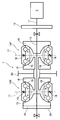
- FIG. 1 is a skeleton diagram of a toroidal-type continuously variable transmission.
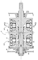
- FIG. 2 is an enlarged view of a main part of FIG.
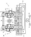
- First embodiment 3 is a cross-sectional view taken along line 3-3 of FIG.
- FIG. 4 is a block diagram of a gear ratio control system.
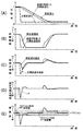
- FIG. 5 is a time chart showing the change characteristics of the transmission ratio, the transmission speed, the transmission acceleration, the transmission acceleration deviation, and the control amount.
- FIG. 6 is an explanatory diagram of the shape of the shift acceleration deviation and the shape of the required thrust of the shift actuator.
- a toroidal-type continuously variable transmission T for an automobile includes an input shaft 13 connected to a crankshaft 11 of an engine E via a damper 12.
- the first continuously variable transmission mechanism 14F and the second continuously variable transmission mechanism 14R having the same structure are supported.
- the first continuously variable transmission mechanism 14F includes a substantially cone-shaped input disk 15 fixed to the input shaft 13, and a substantially cone-shaped output disk 16 supported on the input shaft 13 so as to be relatively rotatable and axially slidable.
- a pair of power rollers 19, 19 that are supported rotatably around the roller shaft 17 and are tiltably supported around the trunnion shafts 18, 18 and can come into contact with the input disk 15 and the output disk 16.
- the opposing surfaces of the input disk 15 and the output disk 16 are formed by toroidal curved surfaces, and when the power rollers 19, 19 tilt around the trunnion shafts 18, 18, the power rollers 19, 19 with respect to the input disk 15 and the output disk 16 The contact point changes.
- the second continuously variable transmission mechanism 14R is disposed substantially in plane symmetry with the first continuously variable transmission mechanism 14F with the drive gear 20 in between, and the output disks of the first and second continuously variable transmission mechanisms 14F and 14R. 16, 16 and the drive gear 20 are integrally formed.
- the input disk 15 of the first continuously variable transmission mechanism 14F is fixed to the input shaft 13
- the input disk 15 of the second continuously variable transmission mechanism 14R is not rotatable relative to the input shaft 13 and moves in the axial direction. It is spline-coupled so as to be slidably fitted into a cylinder 35 formed at the left end of the input shaft 13.
- the input disk 15 of the second continuously variable transmission mechanism 14R and the output disks 16 and 16 of the first and second continuously variable transmission mechanisms 14F and 14R are: It is possible to generate a load that is pressed toward the input disk 15 of the first continuously variable transmission mechanism 14F and suppresses slipping between the input disks 15 and 15 and the output disks 16 and 16 and the power roller 19.
- the first continuously variable transmission mechanism 14F (or the second continuously variable transmission mechanism 14R) includes a pair of left and right trunnions 21 and 21 arranged so as to sandwich the input shaft 13 therebetween.
- the lower part of each trunnion 21 is supported by a lower support plate 22 via a roller bearing 23 so as to be rotatable and slidable up and down.
- one end of a pivot shaft 24 bent in a crank shape is rotatably supported on each trunnion 21, and the power roller 19 is rotatably supported on the other end of the pivot shaft 24.
- Piston rods 28 and 28 of a pair of hydraulic actuators 27 and 27 provided in the hydraulic control blocks 25 and 26 are integrally formed at the lower ends of the trunnions 21 and 21, respectively.
- Each hydraulic actuator 27 is divided into a cylinder 29 formed in the hydraulic control block 25, a piston 30 integrally formed with the piston rod 28 and slidably fitted into the cylinder 29, and a lower side of the piston 30.
- the speed increasing oil chamber 31 and a speed reducing oil chamber 32 partitioned on the upper side of the piston 30 are configured.
- the upper ends of a total of four trunnions 21 are pivotally supported at the four corners of the upper support plate 34 via spherical joints 33, respectively, and the two trunnions 21 and 21 are moved upward to the other two trunnions. When 21 and 21 move downward, their movements are synchronized.
- the shift control valve 43 is connected to a PH hydraulic pressure source 44 that outputs a high PH pressure and a PL hydraulic pressure source 45 that outputs a low PL pressure. Further, two speed increasing oil chambers 31, 31 are connected to the speed change control valve 43 via an oil passage 46, and two speed reducing oil chambers 32, 32 are connected via an oil passage 47.
- the hydraulic actuators 27 and 27 are actuated to operate a pair of trunnions.
- One of 21 and 21 rises from the neutral position and the other falls from the neutral position.
- the power rollers 19, 19 tilt in the direction of arrow a in FIG. 1, the contact point with the input disk 15 moves radially outward with respect to the input shaft 13, and the contact point with the output disk 16 changes. Since it moves radially inward with respect to the input shaft 13, the rotation of the input disk 15 is accelerated and transmitted to the output disk 16, and the gear ratio of the toroidal continuously variable transmission T is continuously reduced.
- the gear ratio changes toward the target gear ratio by driving the pair of trunnions 21 and 21 in the opposite directions from the neutral position by the hydraulic actuators 27 and 27.
- the hydraulic actuators 27 and 27 return the pair of trunnions 21 and 21 to the neutral position, and the thrust of the hydraulic actuators 27 and 27 is transferred to the input disk 15 and the power rollers 19 and 19.
- the target speed ratio is maintained by balancing with the reaction force received from the output disk 16.
- the operation of the second continuously variable transmission mechanism 14R is the same as that of the first continuously variable transmission mechanism 14F described above, and the first and second continuously variable transmission mechanisms 14F and 14R perform a transmission operation in synchronization. Accordingly, the driving force input from the crankshaft 11 of the engine E to the input shaft 13 is steplessly changed at an arbitrary speed ratio within the speed ratio range of the toroidal-type continuously variable transmission T and output from the drive gear 20. Is done.
- the electronic control unit U that controls the gear ratio of the toroidal-type continuously variable transmission T includes a target gear ratio determination unit M1, a target gear shift speed determination unit M2, a target gear shift acceleration determination unit M3, and a gear shift acceleration feedback PID control unit M4.
- the target speed ratio determining unit M1 calculates the target speed ratio of the toroidal continuously variable transmission T based on the rotational speed of the input disk 15, the rotational speed of the output disk 16, the vehicle speed, the accelerator pedal opening degree, and the like.
- the target transmission speed determination unit M2 calculates a target transmission speed that is a time change rate of the target transmission ratio calculated by the target transmission ratio determination unit M1.
- the target shift acceleration determining unit M3 calculates a target shift acceleration that is a time change rate of the target shift speed calculated by the target shift speed determining unit M2.
- the subtractor 51 subtracts the actual shift acceleration calculated based on the rotation speed of the input disk 15 and the rotation speed of the output disk 16 from the target shift acceleration calculated by the target shift acceleration determination unit M3, thereby changing the shift acceleration deviation. Is calculated.
- the shift acceleration feedback PID control unit M4 performs PID processing on the shift acceleration deviation input from the subtractor 51, and calculates a PID feedback control amount for converging the deviation to zero. At that time, the PID gain can be changed based on the friction of the trunnions 21 and 21, which will be described later, the oil temperature of the toroidal continuously variable transmission T, the gear ratio of the toroidal continuously variable transmission T, and the like.
- the shift acceleration feedback execution determination unit M5 determines whether or not feedback control based on shift acceleration can be performed, and permits the shift acceleration feedback PID control unit M4 to execute shift control only when possible. For example, when the engine speed is equal to or lower than the idle speed, the line pressure generated by the oil pump is insufficient, so that the actual speed ratio becomes difficult to follow the target speed ratio and the feedback control amount increases. Therefore, the line pressure is further insufficient and the control becomes unstable. In such a case, since the feedback control based on the shift acceleration cannot be executed accurately, its execution is prohibited.
- the trunnion friction calculation unit M6 is based on the load with which the input disk 15 and the output disk 16 hold the power rollers 19 and 19, the friction coefficient of the sliding part of the trunnions 21 and 21, the gear ratio of the toroidal continuously variable transmission T, and the like. Thus, a control amount corresponding to the friction when the trunnions 21 and 21 move is calculated. The control amount equivalent to the friction calculated by the trunnion friction calculation unit M6 is added to the PID feedback control amount output from the shift acceleration feedback PID control unit M4 in the adder 52.
- the gear ratio maintaining thrust calculating unit M7 calculates a control amount corresponding to the thrust to be generated by the hydraulic actuators 27, 27 in order to maintain the gear ratio constant. This control amount is calculated based on the torque input from the engine E to the toroidal type continuously variable transmission T, the tilt angles of the power rollers 19 and 19, the specifications of the toroidal type continuously variable transmission T, and the like. Then, the control amount corresponding to the thrust of the hydraulic actuators 27, 27 calculated by the transmission ratio maintaining thrust calculation unit M7 is added to the control amount output from the adder 52 in the adder 53, and then the noise component is removed by the filter 54. Then, the opening degree of the flow control valve that supplies the hydraulic pressure to the hydraulic actuators 27 and 27 is controlled.
- FIG. 5A is an example of a target gear ratio obtained from a map or the like.
- the target gear ratio obtained from the map etc. changes abruptly at the start of control, but as shown by the broken line in Fig. 5 (A), the target gear ratio (refer to the chain line) has been taken into account for transient characteristics. Is used as the actual target gear ratio.
- the solid line in FIG. 5A represents the actual speed ratio change characteristic finally obtained by this control.
- the target transmission speed determination unit M2 calculates the target transmission speed according to the target transmission ratio calculated by the target transmission ratio determination unit M1 (see the broken line in FIG. 5A). As indicated by a broken line in FIG. 5B, the target shift speed rapidly rises at the start of the control, whereby the shift actuators 27 and 27 can be quickly operated to improve the control responsiveness. At the end of the control, the target transmission speed returns more slowly than at the start of the control, thereby preventing the actual transmission ratio from overshooting the target transmission ratio. The actual shift speed indicated by the solid line follows the target shift speed indicated by the broken line with a slight delay.
- the target shift acceleration determination unit M3 is a target shift acceleration (see the broken line in FIG. 5C) that is a time change rate of the target shift speed calculated by the target shift speed determination unit M2, and a time change rate of the actual shift speed.
- the actual shift acceleration (see the solid line in FIG. 5C) is calculated.
- the actual shift acceleration indicated by the solid line follows the target shift acceleration indicated by the broken line with a slight delay.
- FIG. 5D shows the deviation of the target shift acceleration with respect to the actual shift acceleration calculated by the shift acceleration feedback PID control unit M4. At the start of the control, a large negative deviation occurs, and then a positive deviation decreases. At the end, a small positive deviation occurs after a slightly large positive deviation.
- FIG. 5E shows a feedforward equivalent to the PID feedback control amount calculated by the shift acceleration feedback PID control unit M4 from the deviation shown in FIG. 5D and the friction of the trunnions 21 and 21 calculated by the trunnion friction calculation unit M6.
- the control amount is obtained by adding the control amount.
- the addition of the feedforward control amount corresponding to the thrust to be generated by the hydraulic actuators 27, 27 calculated by the transmission ratio maintaining thrust calculation unit M7 is omitted.
- the shaded portion indicates the control amount equivalent to the net friction, and the control amount actually added is set slightly smaller than the control amount equivalent to the net friction.
- the control amount for the electronic control unit U to control the opening degree of the shift control valve 43 includes the PID feedback control amount calculated by PID processing of the shift acceleration deviation, and the feed corresponding to the friction of the trunnions 21 and 21. Since it is an addition value of the forward control amount and the control amount corresponding to the thrust to be generated by the hydraulic actuators 27, 27 in order to keep the transmission ratio constant, the trunnions 21, 21 are caused to generate friction and power by the PID feedback control amount. It moves by overcoming the reaction force of the rollers 19, 19, and the transmission ratio of the toroidal type continuously variable transmission T is changed.
- the thrust to be generated by the hydraulic actuators 27 and 27 to maintain the gear ratio by offsetting the feedforward control amount corresponding to the friction of the trunnions 21 and 21 and the reaction force from the power rollers 19 and 19 to the PID feedback control amount. Since the final control amount is output by adding the corresponding feedforward control amount, the gear ratio can be accurately controlled without being affected by the friction of the trunnions 21 and 21 and the reaction force from the power rollers 19 and 19. Can do.
- the feedforward control amount corresponding to the friction of the trunnions 21 and 21 is set slightly smaller than the value corresponding to the actual friction (see FIG. 5E), so that the feedforward control amount becomes excessive and intended. It is possible to avoid a situation where the gear ratio is controlled to a low gear ratio.
- the time chart of FIG. 6 shows the target gear ratio, the target gear speed, the target gear acceleration, the gear shift acceleration deviation, the strokes of the trunnions 21 and 21 necessary for the gear shift, and the thrusts of the hydraulic actuators 27 and 27 required for the strokes of the trunnions 21 and 21.
- the change of is typically shown.
- the shape of the shift acceleration deviation line is similar to the shape of the thrust lines of the hydraulic actuators 27 and 27 required for shifting, and both the former and the latter are unidirectional (see FIG. When the control ends, both the former and the latter change in the other direction (upward in the figure).
- the shift acceleration deviation is directly related to the PID feedback control amount, and the PID feedback control amount is directly related to the thrust of the hydraulic actuators 27 and 27. Therefore, since the shape of the line of the shift acceleration deviation is similar to the shape of the thrust line of the hydraulic actuators 27, 27 required for shifting, if this control is applied to the toroidal continuously variable transmission T, the shift Control can be further stabilized.
- the transmission of the present invention is not limited to the toroidal type continuously variable transmission T of the embodiment, and may be another type of transmission such as a belt type continuously variable transmission.
Landscapes
- Engineering & Computer Science (AREA)
- General Engineering & Computer Science (AREA)
- Mechanical Engineering (AREA)
- Control Of Transmission Device (AREA)
Abstract
Description
16 出力ディスク
18 トラニオン軸
19 パワーローラ
21 トラニオン
27 油圧アクチュエータ
T トロイダル型無段変速機(変速機)
U 電子制御ユニット(制御量算出手段)
Claims (4)
- 変速機(T)の入力回転数および出力回転数間の実変速比を目標変速比に一致させるフィードバック制御量を算出する変速比制御手段(U)を備える変速制御装置であって、
前記制御量算出手段(U)は、前記目標変速比の変化加速度に対する前記実変速比の変化加速度の偏差に基づいて前記フィードバック制御量を算出することを特徴とする変速制御装置。 - 前記変速機(T)は、入力ディスク(15)と、出力ディスク(16)と、前記入力ディスク(15)および前記出力ディスク(16)間に挟持された一対のパワーローラ(19)と、前記一対のパワーローラ(19)を支持する一対のトラニオン(21)と、前記一対のトラニオン(21)に接続された一対の油圧アクチュエータ(27)とを備え、前記一対の油圧アクチュエータ(27)で前記一対のトラニオン(21)を相互に逆方向に駆動し、前記一対のパワーローラ(19)をトラニオン軸(18)まわりに揺動させて前記入力ディスク(15)および前記出力ディスク(16)との接触点の位置を変化させることで変速比を変更するトロイダル型無段変速機であることを特徴とする、請求項1に記載の変速制御装置。
- 前記制御量算出手段(U)は、前記一対のトラニオン(21)のフリクションを算出するとともに、前記フリクションの一部を補償するフィードフォワード制御量を算出し、前記フィードフォワード制御量を前記フィードバック制御量に加算して出力することを特徴とする、請求項2に記載の変速制御装置。
- 前記制御量算出手段(U)は、前記入力ディスク(15)および前記出力ディスク(16)が前記一対のパワーローラ(19)を挟持する押圧力、前記一対のトラニオン(21)の摺動部の摩擦係数および前記変速機(T)の変速比の少なくとも一つに基づいて前記フリクションを算出することを特徴とする、請求項3に記載の変速制御装置。
Priority Applications (3)
| Application Number | Priority Date | Filing Date | Title |
|---|---|---|---|
| US14/769,162 US9523426B2 (en) | 2013-02-21 | 2013-12-16 | Gear change control device |
| CN201380072443.5A CN105190117B (zh) | 2013-02-21 | 2013-12-16 | 变速控制装置 |
| JP2015501287A JP5970730B2 (ja) | 2013-02-21 | 2013-12-16 | 変速制御装置 |
Applications Claiming Priority (2)
| Application Number | Priority Date | Filing Date | Title |
|---|---|---|---|
| JP2013-031662 | 2013-02-21 | ||
| JP2013031662 | 2013-02-21 |
Publications (1)
| Publication Number | Publication Date |
|---|---|
| WO2014129060A1 true WO2014129060A1 (ja) | 2014-08-28 |
Family
ID=51390871
Family Applications (1)
| Application Number | Title | Priority Date | Filing Date |
|---|---|---|---|
| PCT/JP2013/083612 Ceased WO2014129060A1 (ja) | 2013-02-21 | 2013-12-16 | 変速制御装置 |
Country Status (4)
| Country | Link |
|---|---|
| US (1) | US9523426B2 (ja) |
| JP (1) | JP5970730B2 (ja) |
| CN (1) | CN105190117B (ja) |
| WO (1) | WO2014129060A1 (ja) |
Families Citing this family (5)
| Publication number | Priority date | Publication date | Assignee | Title |
|---|---|---|---|---|
| JP6666756B2 (ja) * | 2016-03-09 | 2020-03-18 | ジヤトコ株式会社 | 無段変速機の制御装置及び無段変速機の制御方法 |
| DE102016204356B4 (de) * | 2016-03-16 | 2022-02-10 | Ford Global Technologies, Llc | Verfahren und Vorrichtung zur Längsregelung eines Kraftfahrzeugs |
| CN112660100B (zh) * | 2019-10-16 | 2022-09-30 | 上海汽车集团股份有限公司 | 无级变速器速比控制方法、电子设备及存储介质 |
| JP7650658B2 (ja) * | 2020-12-28 | 2025-03-25 | 株式会社シマノ | 人力駆動車用の制御装置 |
| CN115542785A (zh) * | 2021-06-30 | 2022-12-30 | 大陆泰密克汽车系统(上海)有限公司 | 用于车辆的控制系统及车辆 |
Citations (4)
| Publication number | Priority date | Publication date | Assignee | Title |
|---|---|---|---|---|
| JP2003254423A (ja) * | 2002-02-28 | 2003-09-10 | Mazda Motor Corp | 無段変速機の制御装置 |
| JP2009074668A (ja) * | 2007-09-25 | 2009-04-09 | Jatco Ltd | ベルト式無段変速機のライン圧制御装置 |
| JP2009299814A (ja) * | 2008-06-13 | 2009-12-24 | Toyota Motor Corp | 無段変速機及び変速比制御装置 |
| JP2011185386A (ja) * | 2010-03-10 | 2011-09-22 | Mazda Motor Corp | 車両の制御装置 |
Family Cites Families (18)
| Publication number | Priority date | Publication date | Assignee | Title |
|---|---|---|---|---|
| JP2847781B2 (ja) | 1989-07-28 | 1999-01-20 | 日産自動車株式会社 | 変速機の制御装置 |
| JP2639187B2 (ja) | 1990-07-19 | 1997-08-06 | 日産自動車株式会社 | 摩擦車式無段変速機の変速制御装置 |
| US5293316A (en) | 1991-10-07 | 1994-03-08 | Eaton Corporation | Closed loop launch and creep control for automatic clutch |
| JP2943633B2 (ja) * | 1994-11-16 | 1999-08-30 | 三菱自動車工業株式会社 | 自動変速機の変速制御装置 |
| JP3555386B2 (ja) * | 1997-06-25 | 2004-08-18 | トヨタ自動車株式会社 | 自動変速機の変速制御装置 |
| JP4362907B2 (ja) | 1999-09-28 | 2009-11-11 | 日産自動車株式会社 | トロイダル型無段変速機の変速制御装置 |
| JP3702799B2 (ja) | 2000-05-15 | 2005-10-05 | 日産自動車株式会社 | トロイダル型無段変速機の変速制御装置 |
| CA2352991C (en) * | 2000-07-24 | 2009-01-06 | Honda Giken Kogyo Kabushiki Kaisha | Shift control system for belt-type continuously variable transmission |
| JP3607640B2 (ja) | 2001-06-18 | 2005-01-05 | 本田技研工業株式会社 | 変速機の油圧制御装置 |
| JP3794295B2 (ja) | 2001-07-25 | 2006-07-05 | 日産自動車株式会社 | トロイダル型無段変速機の変速制御装置 |
| JP2003074400A (ja) | 2001-09-04 | 2003-03-12 | Honda Motor Co Ltd | エンジンの回転数制御装置 |
| JP2003120802A (ja) | 2001-10-11 | 2003-04-23 | Nissan Motor Co Ltd | 変速比無限大無段変速機の変速制御装置 |
| CN100386540C (zh) | 2001-10-22 | 2008-05-07 | 洋马农机株式会社 | 油压式变速车辆 |
| JP4284905B2 (ja) | 2001-12-04 | 2009-06-24 | 日産自動車株式会社 | 無段変速機の変速制御装置 |
| US6813551B2 (en) * | 2002-02-04 | 2004-11-02 | Toyota Jidosha Kabushiki Kaisha | Control apparatus for continuously variable transmission |
| CN100470091C (zh) | 2003-02-28 | 2009-03-18 | 福尔布鲁克科技公司 | 连续可变速传动装置 |
| JP4923999B2 (ja) | 2006-12-11 | 2012-04-25 | トヨタ自動車株式会社 | 変速制御装置 |
| JP4962393B2 (ja) | 2008-04-21 | 2012-06-27 | トヨタ自動車株式会社 | 油流制御弁の対向接続による油圧制御装置 |
-
2013
- 2013-12-16 WO PCT/JP2013/083612 patent/WO2014129060A1/ja not_active Ceased
- 2013-12-16 CN CN201380072443.5A patent/CN105190117B/zh not_active Expired - Fee Related
- 2013-12-16 JP JP2015501287A patent/JP5970730B2/ja not_active Expired - Fee Related
- 2013-12-16 US US14/769,162 patent/US9523426B2/en not_active Expired - Fee Related
Patent Citations (4)
| Publication number | Priority date | Publication date | Assignee | Title |
|---|---|---|---|---|
| JP2003254423A (ja) * | 2002-02-28 | 2003-09-10 | Mazda Motor Corp | 無段変速機の制御装置 |
| JP2009074668A (ja) * | 2007-09-25 | 2009-04-09 | Jatco Ltd | ベルト式無段変速機のライン圧制御装置 |
| JP2009299814A (ja) * | 2008-06-13 | 2009-12-24 | Toyota Motor Corp | 無段変速機及び変速比制御装置 |
| JP2011185386A (ja) * | 2010-03-10 | 2011-09-22 | Mazda Motor Corp | 車両の制御装置 |
Also Published As
| Publication number | Publication date |
|---|---|
| JPWO2014129060A1 (ja) | 2017-02-02 |
| CN105190117B (zh) | 2017-03-22 |
| US9523426B2 (en) | 2016-12-20 |
| US20150377348A1 (en) | 2015-12-31 |
| JP5970730B2 (ja) | 2016-08-17 |
| CN105190117A (zh) | 2015-12-23 |
Similar Documents
| Publication | Publication Date | Title |
|---|---|---|
| JP5970730B2 (ja) | 変速制御装置 | |
| KR101179284B1 (ko) | 무단 변속기의 제어 방법 | |
| JP2015190487A (ja) | 無段変速機の制御装置 | |
| US9562546B2 (en) | Hydraulic control circuit and its control method | |
| JP4586433B2 (ja) | トロイダル型無段変速機の変速制御装置 | |
| JP5176496B2 (ja) | トロイダル型無段変速機 | |
| JP5152040B2 (ja) | 変速制御装置 | |
| JP6157618B2 (ja) | トロイダル型無段変速機 | |
| JP2001107992A (ja) | 無段変速機のための発進クラッチ制御装置 | |
| JP6032612B2 (ja) | トロイダル型無段変速機の挟圧力制御装置 | |
| JP6120319B2 (ja) | 無段変速機の制御装置 | |
| JP2005069455A (ja) | 無段変速機の変速比制御装置 | |
| JP2006009908A (ja) | トロイダル型無段変速機の変速制御装置 | |
| JP5152039B2 (ja) | 変速制御装置 | |
| JP4644788B2 (ja) | トロイダル式cvtの制御装置 | |
| JP4649907B2 (ja) | 無段変速機の制御装置 | |
| JP2007198509A (ja) | トロイダル型無段変速機の変速制御装置 | |
| JP2006513378A (ja) | トロイダル制御装置 | |
| JP5447609B2 (ja) | トロイダル型無段変速機及び無段変速装置 | |
| JP4003880B2 (ja) | トロイダル型無段変速機の変速制御装置 | |
| JPH07259948A (ja) | トロイダル型無段変速装置 | |
| JP2007170611A (ja) | 車両用トロイダル式無段変速機 | |
| JP2009222160A (ja) | 変速制御装置 | |
| JP2002349691A (ja) | トロイダル型無段変速機の変速制御装置 | |
| JP2007170497A (ja) | トロイダル型無段変速機の変速制御装置 |
Legal Events
| Date | Code | Title | Description |
|---|---|---|---|
| WWE | Wipo information: entry into national phase |
Ref document number: 201380072443.5 Country of ref document: CN |
|
| 121 | Ep: the epo has been informed by wipo that ep was designated in this application |
Ref document number: 13875408 Country of ref document: EP Kind code of ref document: A1 |
|
| ENP | Entry into the national phase |
Ref document number: 2015501287 Country of ref document: JP Kind code of ref document: A |
|
| WWE | Wipo information: entry into national phase |
Ref document number: 14769162 Country of ref document: US |
|
| NENP | Non-entry into the national phase |
Ref country code: DE |
|
| 122 | Ep: pct application non-entry in european phase |
Ref document number: 13875408 Country of ref document: EP Kind code of ref document: A1 |