WO2014118830A1 - 燃料タンクの車体取付構造および燃料タンクの変形防止具 - Google Patents
燃料タンクの車体取付構造および燃料タンクの変形防止具 Download PDFInfo
- Publication number
- WO2014118830A1 WO2014118830A1 PCT/JP2013/005635 JP2013005635W WO2014118830A1 WO 2014118830 A1 WO2014118830 A1 WO 2014118830A1 JP 2013005635 W JP2013005635 W JP 2013005635W WO 2014118830 A1 WO2014118830 A1 WO 2014118830A1
- Authority
- WO
- WIPO (PCT)
- Prior art keywords
- fuel tank
- band
- vehicle body
- coupled
- upper wall
- Prior art date
Links
Images


Classifications
-
- B—PERFORMING OPERATIONS; TRANSPORTING
- B60—VEHICLES IN GENERAL
- B60K—ARRANGEMENT OR MOUNTING OF PROPULSION UNITS OR OF TRANSMISSIONS IN VEHICLES; ARRANGEMENT OR MOUNTING OF PLURAL DIVERSE PRIME-MOVERS IN VEHICLES; AUXILIARY DRIVES FOR VEHICLES; INSTRUMENTATION OR DASHBOARDS FOR VEHICLES; ARRANGEMENTS IN CONNECTION WITH COOLING, AIR INTAKE, GAS EXHAUST OR FUEL SUPPLY OF PROPULSION UNITS IN VEHICLES
- B60K15/00—Arrangement in connection with fuel supply of combustion engines or other fuel consuming energy converters, e.g. fuel cells; Mounting or construction of fuel tanks
- B60K15/03—Fuel tanks
- B60K15/063—Arrangement of tanks
- B60K15/067—Mounting of tanks
-
- B—PERFORMING OPERATIONS; TRANSPORTING
- B60—VEHICLES IN GENERAL
- B60K—ARRANGEMENT OR MOUNTING OF PROPULSION UNITS OR OF TRANSMISSIONS IN VEHICLES; ARRANGEMENT OR MOUNTING OF PLURAL DIVERSE PRIME-MOVERS IN VEHICLES; AUXILIARY DRIVES FOR VEHICLES; INSTRUMENTATION OR DASHBOARDS FOR VEHICLES; ARRANGEMENTS IN CONNECTION WITH COOLING, AIR INTAKE, GAS EXHAUST OR FUEL SUPPLY OF PROPULSION UNITS IN VEHICLES
- B60K15/00—Arrangement in connection with fuel supply of combustion engines or other fuel consuming energy converters, e.g. fuel cells; Mounting or construction of fuel tanks
- B60K15/03—Fuel tanks
- B60K15/063—Arrangement of tanks
- B60K2015/0634—Arrangement of tanks the fuel tank is arranged below the vehicle floor
-
- B—PERFORMING OPERATIONS; TRANSPORTING
- B60—VEHICLES IN GENERAL
- B60K—ARRANGEMENT OR MOUNTING OF PROPULSION UNITS OR OF TRANSMISSIONS IN VEHICLES; ARRANGEMENT OR MOUNTING OF PLURAL DIVERSE PRIME-MOVERS IN VEHICLES; AUXILIARY DRIVES FOR VEHICLES; INSTRUMENTATION OR DASHBOARDS FOR VEHICLES; ARRANGEMENTS IN CONNECTION WITH COOLING, AIR INTAKE, GAS EXHAUST OR FUEL SUPPLY OF PROPULSION UNITS IN VEHICLES
- B60K15/00—Arrangement in connection with fuel supply of combustion engines or other fuel consuming energy converters, e.g. fuel cells; Mounting or construction of fuel tanks
- B60K15/03—Fuel tanks
- B60K15/063—Arrangement of tanks
- B60K2015/0636—Arrangement of tanks the fuel tank being part of the chassis or frame
-
- B—PERFORMING OPERATIONS; TRANSPORTING
- B60—VEHICLES IN GENERAL
- B60K—ARRANGEMENT OR MOUNTING OF PROPULSION UNITS OR OF TRANSMISSIONS IN VEHICLES; ARRANGEMENT OR MOUNTING OF PLURAL DIVERSE PRIME-MOVERS IN VEHICLES; AUXILIARY DRIVES FOR VEHICLES; INSTRUMENTATION OR DASHBOARDS FOR VEHICLES; ARRANGEMENTS IN CONNECTION WITH COOLING, AIR INTAKE, GAS EXHAUST OR FUEL SUPPLY OF PROPULSION UNITS IN VEHICLES
- B60K15/00—Arrangement in connection with fuel supply of combustion engines or other fuel consuming energy converters, e.g. fuel cells; Mounting or construction of fuel tanks
- B60K15/03—Fuel tanks
- B60K15/063—Arrangement of tanks
- B60K15/067—Mounting of tanks
- B60K2015/0675—Mounting of tanks allowing deflection movements of the tank in case of a crash
-
- Y—GENERAL TAGGING OF NEW TECHNOLOGICAL DEVELOPMENTS; GENERAL TAGGING OF CROSS-SECTIONAL TECHNOLOGIES SPANNING OVER SEVERAL SECTIONS OF THE IPC; TECHNICAL SUBJECTS COVERED BY FORMER USPC CROSS-REFERENCE ART COLLECTIONS [XRACs] AND DIGESTS
- Y10—TECHNICAL SUBJECTS COVERED BY FORMER USPC
- Y10T—TECHNICAL SUBJECTS COVERED BY FORMER US CLASSIFICATION
- Y10T137/00—Fluid handling
- Y10T137/8593—Systems
- Y10T137/85978—With pump
Definitions
- the present invention relates to a fuel tank body mounting structure for mounting a fuel tank to a vehicle body, and a deformation preventing device for preventing deformation of the fuel tank.
- Patent Document 1 In order to attach the fuel tank to the vehicle body, a band is bridged in a groove formed on the surface of the fuel tank, both ends of the band are bolted to the vehicle body, and the surface of the fuel tank is pressed against the vehicle body by a rubber cushion and fixed.
- Patent Document 1 This configuration can suppress independent vibration of the fuel tank.
- a fixing member in which a metal screw member (for example, a nut) is embedded in a resin member in which a permeation-resistant resin and a welding / adhesive resin are integrally formed in multiple layers is welded to the upper surface of the fuel tank.
- Patent Document 3 A configuration in which a tank is attached to a vehicle body is known (Patent Document 3). According to Patent Document 3, the fuel tank can be firmly attached to the vehicle body by this configuration.
- the mounting structure is for attaching an accessory such as a protector to the outside of the fuel tank.
- the recess is formed on the surface of the fuel tank, the accessory having a through hole and attached to the outside of the fuel tank, and the fuel tank.
- Patent Document 4 There is known a configuration in which the second fastener is inserted through a through hole and engaged with a claw provided on the inner periphery of the recess.
- Patent Document 4 According to Patent Document 4, according to this configuration, the accessory part can be attached to the fuel tank only by providing a recess on the surface of the fuel tank.
- the fuel tank In a typical front engine passenger car, the fuel tank is often mounted horizontally under the floor near the rear seat. This is to avoid damage caused by a collision and to reduce the influence of the amount of fuel on the position of the center of gravity of the vehicle body and the moment of inertia of the vehicle body.
- the fuel tank is exposed to changes in the outside air temperature and temperature changes due to the heat of the exhaust.
- the material of the fuel tank has changed from steel plate to resin. This is because resin tanks have a penetration and fracture strength that is slightly inferior to those of steel plates, but they are light in weight without generating rust and have the advantage that they can be mass-produced at low cost even with complex shapes.
- the fuel tank is negatively charged as the pump module transports gasoline from the fuel tank.
- the phenomenon that becomes pressure is known. If the discharge force of the pump module is increased with the adoption of an electronically controlled fuel injection device or the like, fuel may be forcibly discharged even if the fuel tank becomes negative pressure, and the fuel tank may be damaged.
- An object of the present invention is to provide a vehicle body mounting structure for a fuel tank and a fuel tank deformation prevention tool capable of preventing harmful deformation that hinders the function of the fuel tank.
- the present invention is a vehicle tank mounting structure for a fuel tank, which is fixed to the vehicle body and extends along at least a lower wall (19L) of the fuel tank (1) to hold the fuel tank.
- a fuel tank vehicle body mounting structure comprising upper wall coupling means (40) for coupling at least one of the upper walls of the fuel tank to the holding member.
- the holding member extends along the upper wall (19U) of the fuel tank (1) and cooperates with the band lower (10L) to surround the fuel tank (10U).
- the upper wall coupling means (40) is configured to couple the upper wall of the fuel tank to the band upper.
- the cooperation of the band lower and the band upper makes it possible to prevent the fuel tank from being deformed even when the internal pressure of the fuel tank changes to either positive pressure or negative pressure.
- the fuel tank (1) is a resin tank having a recess (32) formed on a surface thereof, and the lower wall coupling means (40) and the upper wall coupling means (40) In this embodiment, a coupled member (41) fixed to the surface of the fuel tank is included.
- the strength of the fuel tank itself is improved by the recesses to prevent the deformation of the fuel tank, and the coupled member does not protrude greatly from the surface of the fuel tank. Therefore, even if the band lower and the band upper are included, the fuel tank The height of the vehicle body attachment structure can be kept low, and the fuel tank can be compactly attached to the vehicle body.
- the coupled member (41) includes an insert bolt (42b) or an insert nut provided integrally by insert molding, and a nut (44) screwed into the insert bolt (42b) or the insert nut. Or it is comprised so that a volt
- the band lower (10L) and the band upper (10U) are provided with the insert bolt (42b) or a through hole through which the bolt is inserted, and the size of the through hole includes the insert to be inserted.
- a predetermined play is set at least in the extending direction of the band lower and the band upper with respect to the bolt (42b) or the outer diameter of the bolt.
- the band lower and the band upper are made of resin and made of metal. It is possible to absorb a difference in linear expansion coefficient (that is, a difference in thermal expansion) such as a band lower.
- the lower wall coupling means (40) couples the lower wall (19L) of the fuel tank (1) to the band lower (10L) in a non-contact manner via the coupled member (41).
- the upper wall coupling means (40) is configured to couple the upper wall of the fuel tank in a non-contact manner with the band upper (10U) through the coupled member.
- the band lower (10L) and the band upper (10U) have flange portions (18) overlapping each other at their end portions, and the band lower and the band upper are attached to the vehicle body by the flange portions. It is configured to be fixed.
- the flange portion (18) is provided with a long hole whose major axis is the extending direction of the band lower (10L) and the band upper (10U), and the flange portion is arranged in a direction along the vehicle body. It is slidable.
- a pump module for sending fuel is joined to the upper wall (19U) of the fuel tank (1), and a plurality of upper wall coupling means (40) are provided in the vicinity of the pump module. Is.
- the cross section orthogonal to the extending direction of the band lower (10L) and the band upper (10U) is formed into a substantially hat shape.
- the present invention also provides a plurality of coupled members (41) provided on the surface of the fuel tank (1) and a plurality of bands (coupled to the coupled members and provided along the surface of the fuel tank ( 10), and a fuel tank deformation preventing device configured to connect the plurality of bands so that the plurality of bands make at least one round of the fuel tank along the surface of the fuel tank. .
- the band (10) extends along the lower wall (19L) of the fuel tank and holds the fuel tank (1), and the upper wall (10L) of the fuel tank ( 19U) and a band upper (10U) surrounding the fuel tank in cooperation with the band lower, and the coupled member (41) is at least one of the lower wall of the fuel tank
- the band upper has flange portions (18) that overlap each other at the end portion, and the band lower and the band upper are connected by the flange portion.
- the band lower and the band upper connected by the flange portion cooperate to prevent deformation of the fuel tank even when the internal pressure of the fuel tank changes to either positive pressure or negative pressure. It becomes possible.
- the fuel tank (1) is a resin tank having a recess (32) formed on a surface thereof, and the member to be coupled (41) is disposed in the recess.
- the strength of the fuel tank itself is improved by the recesses to prevent the deformation of the fuel tank, and the coupled member does not protrude greatly from the surface of the fuel tank. Therefore, even if the band lower and the band upper are included, the fuel tank The height of the deformation preventing tool can be kept low, and a compact configuration can be achieved.
- the coupled member (41) includes an insert bolt (42b) or an insert nut provided integrally by insert molding, and a nut (44) or a bolt that is screwed to the insert bolt or the insert nut. It is configured to include.
- the band lower (10L) and the band upper (10U) are provided with the insert bolt (42b) or a through hole through which the bolt is inserted, and the size of the through hole includes the insert to be inserted.
- a predetermined play is set at least in the extending direction of the band lower and the band upper with respect to the bolt (42b) or the outer diameter of the bolt.
- the band lower and the band upper are made of resin and made of metal. It is possible to absorb a difference in linear expansion coefficient (that is, a difference in thermal expansion) such as a band lower.
- the lower wall coupling means (40) couples the lower wall (19L) of the fuel tank (1) to the band lower (10L) in a non-contact manner via the coupled member (41).
- the upper wall coupling means (40) is configured to couple the upper wall (19U) of the fuel tank in a non-contact manner with the band upper (10U) through the coupled member.
- the fuel tank (1) is attached to the vehicle body via the flange portion (18).
- a pump module for sending fuel is joined to the upper wall (19U) of the fuel tank (1), and a plurality of upper wall coupling means (40) are provided in the vicinity of the pump module. Is.
- one of the lower wall coupling means (40) is configured such that the band lower (10L) is connected to the lower wall (10U) at a position facing the position where the pump module is joined on the upper wall (19U). 19L).
- the cross section orthogonal to the extending direction of the band lower (10L) and the band upper (10U) is formed into a substantially hat shape.
- the present invention it is possible to prevent deformation of the fuel tank even when the internal pressure of the fuel tank changes to either positive pressure or negative pressure, and to prevent destruction of equipment and the fuel tank built in the fuel tank. Is possible.
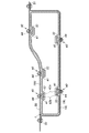
- 1 is a perspective view showing a vehicle tank mounting structure for a fuel tank according to a first embodiment of the present invention, and an overall configuration of the fuel tank.
- the top view which shows the vehicle body mounting structure of the fuel tank which concerns on 1st Embodiment of this invention.
- the bottom view which shows the vehicle body mounting structure of the fuel tank which concerns on 1st Embodiment of this invention
- Fig. 3 is a cross-sectional view showing the main part of the VII-VII cross section in Fig.
- FIG. 3 (A), (b) is a top view which shows the structure of area
- (A), (b), (c) are the principal part sectional drawings which show the principal part of the XX cross section of FIG. Sectional drawing which shows the outline of the vehicle body mounting structure of the fuel tank which concerns on 2nd Embodiment of this invention
- directions are expressed as front, back, left, right, up, and down based on the recognition of the driver who gets in the driver's seat of the car.
- the left-right direction may be expressed as the vehicle width direction.
- FIG. 1 is a top view showing a fuel tank 1 attached to a vehicle body in the first embodiment of the present invention.
- the fuel tank 1 is located under the floor near the rear seat, and is arranged such that its longitudinal direction is the vehicle width direction and its short direction is the front-rear direction.
- the body frame of an automobile includes a pair of left and right rear side frames 2, 2, and the first cross member 3, the second cross member 4, and the rear side frames 2, 2 extend in the vehicle width direction.
- the third cross member 5 is connected.
- the fuel tank 1 is disposed between the first cross member 3 and the second cross member 4.
- a band upper 10 ⁇ / b> U is bridged along the upper wall 19 ⁇ / b> U of the fuel tank 1.
- the band lower 10 ⁇ / b> L is bridged along the lower wall 19 ⁇ / b> L (see FIG. 4) of the fuel tank 1.
- the band upper 10U and the band lower 10L may be collectively referred to as the band 10).
- the fuel tank 1 is attached to the vehicle body via the band 10.
- the front end of the band 10 spanned in the front-rear direction is fixed to the first cross member 3 at two positions P5 and P6, and the rear end is fixed to the second cross member 4 at two positions P2 and P3. It is fixed.
- the left end and the right end of the band 10 spanned in the left-right direction are fixed to the rear side frames 2 and 2 by P1 and P4, respectively.
- the band upper 10U and the band lower 10L are both fixed to the vehicle body side and constitute a holding member for holding the fuel tank 1.
- a canister 12 is provided between the second cross member 4 and the third cross member 5.
- Gasoline which is a fuel for automobiles, has high volatility and is vaporized in the fuel tank 1 to become gasoline vapor. When this gasoline vapor is discharged into the atmosphere, it combines with oxygen and nitrogen compounds to turn into harmful substances.
- the canister 12 is mounted between the fuel tank 1 and an engine (not shown), and prevents the discharge of gasoline vapor that causes air pollution.
- a cut-off valve (not shown) is joined to the fuel tank 1 at a portion indicated as a cut-off valve mounting position 15.
- the cut-off valve normally has a valve body that discharges gasoline vapor generated in the fuel tank 1 and blocks fuel leakage when the vehicle body is reversed.
- the cut-off valve and the canister 12 are vented. It communicates with a tube (not shown).
- the gasoline vapor discharged from the cut-off valve side is adsorbed by activated carbon or the like filled in the canister 12.
- FIG. 1 shows the work in progress in the manufacturing process for the sake of simplicity, but the final product is provided with a mounting flange (not shown) that detachably covers the opening 17, and a stay (FIG.
- the pump module is supported via (not shown).
- a feed pipe (not shown) is connected to the engine (not shown) from the pump module through the mounting flange.
- FIG. 2 is a perspective view showing a vehicle body mounting structure of the fuel tank 1 according to the first embodiment of the present invention and the entire configuration of the fuel tank 1
- FIG. 3 is a diagram of the fuel tank 1 according to the first embodiment of the present invention. It is a top view which shows a vehicle body attachment structure.
- the configuration of the band 10 surrounding the fuel tank 1, in particular, the band upper 10 ⁇ / b> U spanned on the upper wall 19 ⁇ / b> U of the fuel tank 1 will be described in detail with reference to FIGS. 2 and 3.
- the fuel tank 1 has an upper wall 19U and a lower wall 19L.
- the upper wall 19U and the lower wall 19L may not be clearly distinguished. Therefore, here, when the fuel tank 1 is divided into two in the vertical direction, the wall constituting the upper side is It is referred to as a wall 19U, and a wall constituting the lower side is referred to as a lower wall 19L.
- the upper wall 19 ⁇ / b> U or the lower wall 19 ⁇ / b> L may simultaneously form the side wall of the fuel tank 1.
- two band uppers 10UR and 10UL are bridged over the upper wall 19U of the fuel tank 1 in the front-rear direction.
- the two band uppers 10UR and 10UL are disposed so as to be inclined from the rear to the front of the fuel tank 1 so that the distance between the two in the vehicle width direction gradually decreases.
- the band upper 10URR is joined to the right band upper 10UR by welding at a substantially central portion in the front-rear direction of the fuel tank 1, and the band upper 10URR extends from the joined portion toward the right side of the vehicle body. Yes.
- the band upper 10UL is joined to the left band upper 10UL by welding, and the band upper 10ULL extends from the joined portion toward the left side of the vehicle body.
- a band upper 10US that connects these two band uppers 10UR and 10UL in the vehicle width direction is joined to a substantially central portion in the front-rear direction of the band upper 10UR and the band upper 10UL by welding.
- the band upper 10US is disposed so as to surround the opening 17 in the vicinity of the opening 17 at the pump module mounting position 16. That is, the band upper 10US has an annular shape surrounding the opening 17 in a top view.
- the band uppers 10UR, 10UL, 10URR, 10ULL, and 10US may be collectively referred to as a band upper 10U.
- the band uppers 10UR, 10UL, 10URR, 10ULL, and 10US are joined together by welding to form an integral body.
- the band upper 10U is handled as one member.
- the band upper 10U is coupled to the upper wall 19U of the fuel tank 1. Specifically, the band upper 10UR is in PU3, the band upper 10URR is in PU1 and PU2, the band upper 10UL is in PU6, the band upper 10UL is in PU7 and PU8, and the band upper 10US is in PU4 and PU6 above the fuel tank 1. It couple
- the band upper 10US surrounds the opening 17 of the pump module mounting position 16, and the upper wall 19U of the fuel tank 1 and the band upper 10US are located very close to the pump module mounting position 16 (PU4, PU5). Join with.
- the deformation of the fuel tank 1 is prevented particularly near the pump module mounting position 16, and the pump module and its peripheral mechanism (not shown) can be prevented from being destroyed.
- At least one place (either one of PU4 and PU5) of the upper wall 19U is coupled to a holding member (band upper 10U) that holds the fuel tank 1 on the vehicle body. Deformation is prevented locally, and destruction of the device built in the fuel tank 1 is prevented.
- buffer members 20 are provided at two positions near the front and rear, respectively.
- a buffer member 21 is provided at the center in the vehicle width direction of the fuel tank 1 and at the rear in the front-rear direction.
- the buffer member 20 is mainly composed of an elastic body such as rubber, and includes a convex portion (not shown) protruding downward at the center thereof.
- the buffer member 20 is attached to the fuel tank 1 by fitting the convex portion into a concave portion (not shown) provided on the upper wall 19U.
- the buffer member 21 is a rubber member having an uneven surface, and is bonded to an approximately middle position between the cut-off valve mounting position 15 and the pump module mounting position 16 on the upper wall 19U using an adhesive. .
- the buffer member 20 may have the same configuration as the above-described upper wall coupling means, and in addition to this, an elastic body may be disposed on the vehicle body side.
- FIG. 4 is a bottom view showing the vehicle body mounting structure of the fuel tank 1 according to the first embodiment of the present invention.
- two band lowers 10LR and 10LL are bridged in the front-rear direction.
- the two band lowers 10LR and 10LL are arranged so as to be inclined from the rear to the front of the fuel tank 1 so that the distance between the two in the vehicle width direction gradually decreases.
- a band lower 10LRR is joined to the right band lower 10LR by welding at a substantially central portion in the front-rear direction of the fuel tank 1, and the band lower 10LRR extends from the joined portion toward the right side of the vehicle body.
- the band lower 10LLL is joined to the left band lower 10LL by welding, and the band lower 10LLL extends from the joining portion toward the left side of the vehicle body.
- a band lower 10LS that connects these two band lowers 10LR and 10LL in the vehicle width direction is joined to the substantially central portion in the front-rear direction of the band lower 10LR and the band lower 10LL by welding.
- the band lower 10LS extends in the vehicle width direction at a position just behind the pump module mounting position 16 provided on the upper wall 19U of the fuel tank 1.
- the band lowers 10LR, 10LL, 10LRR, 10LLL, and 10LS may be collectively referred to as the band lower 10L.
- the band lower 10L is also joined together by welding similarly to the band upper 10U, and the band lower 10L is handled as one member in the vehicle body mounting structure of the fuel tank 1.
- the band lower 10L is coupled to the lower wall 19L of the fuel tank 1.
- the band lower 10LR is PL6, PL7
- the band lower 10LR is PL8, PL9
- the band lower 10LL is PL3, PL4
- the band lower 10LLL is PL1, PL2
- the band lower 10LS is PL5, and the lower wall 19L of the fuel tank 1.
- the band lower 10LS is just behind the pump module mounting position 16 and extends in the vehicle width direction. Then, the lower wall 19L of the fuel tank 1 and the band lower 10LS are coupled to each other just behind the pump module mounting position 16 (PL5). This prevents the fuel tank 1 from being deformed, particularly in the vicinity of the pump module mounting position 16, and can prevent the pump module and its peripheral mechanism (not shown) from being damaged.
- At least one portion of the lower wall 19L is coupled to a holding member (band lower 10L) that holds the fuel tank 1 on the vehicle body, so that deformation of the fuel tank 1 is locally prevented, and the fuel tank 1 is prevented from being destroyed.
- a holding member band lower 10L
- FIG. 5 is a side view showing the vehicle body mounting structure of the fuel tank 1 according to the first embodiment of the present invention.
- the end of the band upper 10U spanned along the upper wall 19U of the fuel tank 1 and the end of the band lower 10L spanned along the lower wall 19L are P3, P4. , P5 overlap with each other to form the flange portion 18.
- the rear ends of the band upper 10UL and the band lower 10LL overlap at P3, the ends of the band upper 10ULL and the band lower 10LLL overlap at P4, and the front ends of the band upper 10UR and the band lower 10LR overlap at P5.
- These overlapping portions constitute the flange portion 18.
- FIG. 5 shows the left side of the fuel tank 1, but on the right side of the fuel tank 1, the ends of the band upper 10URR and the band lower 10LRR overlap at P1, and the band upper at P2.
- the rear ends of 10UR and the band lower 10LR are overlapped, and the front ends of the band upper 10UR and the band lower 10LR are overlapped at P6 (see FIGS. 3 and 4), and these overlapping portions constitute the flange portion 18.
- the overlapping band upper 10 ⁇ / b> U and band lower 10 ⁇ / b> L are fixed to the vehicle body by the flange portion 18. Further, the band upper 10 ⁇ / b> U and the band lower 10 ⁇ / b> L are connected at the flange portion 18 so that the entire circumference of the fuel tank 1 is surrounded by the band 10.
- FIG. 6 is an explanatory diagram for explaining a manufacturing process of the fuel tank 1.
- the fuel tank 1 is manufactured by blow molding using a resin material and has a multilayer (three layers) structure in the thickness direction.
- the manufacturing process of the fuel tank 1 will be described.
- the blow molding apparatus 22 for blow molding the fuel tank 1 includes first to third extruders 23a, 23b, 23c for extruding molten resin, and first to third extruders 23a, 23b, First to third dies 24a, 24b, and 24c connected to 23c, and a blow molding die 25 arranged below the first to third dies 24a, 24b, and 24c, respectively.
- the resin material extruded from the first extruder 23a constitutes the innermost layer of the fuel tank 1
- the resin material extruded from the third extruder 23c constitutes the outermost layer of the fuel tank 1, from the second extruder 23b.
- the extruded material constitutes the intermediate layer of the fuel tank 1.
- the resin material extruded from the 1st extruder 23a and the 3rd extruder 23c is the same, Comprising:
- a high density polyethylene is used.
- the resin material extruded from the second extruder 23b may be, for example, a material in which a fine sheet-like polyamide sheet material is mixed into high-density polyethylene in order to form a barrier layer.
- the blow molding die 25 includes a first half 25a and a second half 25b that can be freely opened and closed.
- a pin hole 28 for inserting an air pin 27 into the cavity 26 is formed in the first half body 25a. Air is supplied to the air pin 27 from an air supply source 29.
- the molten resin extruded from the first to third extruders 23a, 23b, 23c is used for the first to third dies 24a, 24b, 24c. Is formed, and a three-layer cylindrical parison 100 is formed, and the parison 100 is sandwiched between the first and second halves 25a and 25b of the blow molding die 25. Subsequently, as shown in FIG. 6B, by inserting an air pin 27 into the pin hole 28 of the first half 25a and piercing the parison 100, and supplying air from the air supply source 29 into the parison 100, The parison 100 is expanded and brought into close contact with the wall surface of the cavity 26.
- the fuel tank 1 is molded by separating the first half 25a and the second half 25b.
- the inner surface shape of the fuel tank 1 is not regulated, but the outer surface shape is determined solely by the mold, and it is complicated by increasing the dimensional accuracy of the mold or appropriately setting the surface roughness.
- the fuel tank 1 having a shape can be manufactured with a predetermined surface roughness.
- a recess 32 (see FIG. 7) provided on the surface of the fuel tank 1 to be described later can also be easily formed by this process.
- FIG. 7 is a cross-sectional view showing the main part of the VII-VII cross section of FIG.
- FIG. 7 shows a cross section orthogonal to the extending direction D1 of the band upper 10URR for the portion shown as region A1 in FIG.
- the specific configuration of the upper wall coupling means and the lower wall coupling means in the first embodiment will be described in detail with reference to FIG.
- the difference between the upper wall coupling means for coupling the upper wall 19U of the fuel tank 1 to the band upper 10U and the lower wall coupling means for coupling the lower wall 19L of the fuel tank 1 to the band lower 10L is simply the upper and lower portions of the fuel tank 1. Therefore, in the following description, the upper wall coupling means provided mainly on the upper wall 19U will be described, and the upper wall coupling means will be simply referred to as the coupling means 40. I will explain.
- the fuel tank 1 has a three-layer structure in the thickness direction, and a high-density polyethylene layer 30, a polyamide sheet mixed layer (barrier layer) 31, and a high-density polyethylene layer 30 are laminated in order from the inside. ing.
- the high density polyethylene layer 30 is excellent in mechanical strength
- the polyamide sheet mixed layer 31 is excellent in the barrier properties of hydrocarbons such as gasoline and alcohol.
- the coupling means 40 includes, for example, a coupled member 41 in which an insert bolt 42b is insert-molded in a high-density polyethylene base 42a, and a washer 43 that is screwed to the insert bolt 42b to couple the coupled member 41 to the band upper 10U. And a nut 44.
- the coupled member 41 has a structure in which the shaft of the insert bolt 42b protrudes from the base 42a.
- the description will be made on the assumption that the insert bolt 42b is provided on the base 42a of the member 41 to be coupled.
- an insert nut (not shown) is insert-molded on the base 42a, and the member 41 is coupled.
- the band upper 10U may be coupled by a washer 43 and a bolt (not shown) (the same applies to the second embodiment).
- the bolt is tightened after the band upper 10U is attached. Therefore, if the tightening torque becomes too large, the shaft of the bolt may damage the fuel tank 1, and the tightening torque Should be managed more appropriately.
- the to-be-coupled member 41 is fixed to the bottom surface of the concave portion 32 whose side surface provided on the upper wall 19U of the fuel tank 1 has a tapered shape by heat welding. Providing the recess 32 in the fuel tank 1 improves the mechanical strength of the fuel tank 1 itself.
- the member 41 to be coupled is fixed to the bottom surface of the recess 32 so that the member 41 does not protrude significantly from the upper wall 19U of the fuel tank 1, and even if the band upper 10U is coupled thereto, the fuel tank Thus, the height of the entire vehicle body mounting structure 1 can be kept low, and the fuel tank 1 can be mounted compactly on the vehicle body.
- the material of the outermost layer of the member 41 and the fuel tank 1 are both high-density polyethylene, the same material is bonded extremely firmly at the molecular level by heat welding. Further, instead of heat welding, high frequency welding or ultrasonic welding may be used. Regardless of the method, both are firmly bonded at the molecular level.
- the member to be coupled 41 may be fixed to the fuel tank 1 using, for example, an adhesive.
- the band upper 10U is obtained, for example, by press forming a cold rolled steel sheet having a tensile strength of 270 N / mm 2 or more. However, individual parts constituting the above-described band upper 10U are obtained by press molding (see FIGS. 2 and 3). The final band upper 10U is completed by welding and connecting these parts. Of course, you may make it manufacture the band upper 10U collectively by press molding.
- the cross section of the band upper 10U has a so-called hat shape, and ensures rigidity against bending stress.
- the upper wall coupling means (lower wall coupling means) 40 is a member to be coupled 41 provided on the upper wall 19U (lower wall 19L) of the fuel tank 1.
- the band upper 10U (band lower 10L) itself has high rigidity, and such a highly rigid member surrounds the entire circumference of the fuel tank 1, so that the fuel tank 1 does not expand or contract due to a change in internal pressure. The deformation is regulated from the outside.
- FIG. 8A and 8B are top views showing the configuration of the region A1 in FIG.
- FIG. 8A shows a state in which the band upper 10U is placed on the member to be coupled 41 constituting the coupling means 40
- FIG. 8B shows the state of the member 41 to be coupled from the state of FIG.
- the state where the washer 43 and the nut 44 are attached to the insert bolt 42b, that is, the state where the fuel tank 1 (here, the upper wall 19U) is coupled to the band upper 10U is shown.
- the band upper 10U hides the configuration below the band upper 10U, so that the recess 32, the coupled member 41, and the base 42a provided on the surface of the fuel tank 1 are used. Is drawn as an imaginary line (two-dot chain line).
- the band upper 10U is provided with a through hole 45 for inserting the insert bolt 42b.
- the through hole 45 is a long hole having a long diameter in the extending direction D1 of the band upper 10U.
- the band upper 10U through which the insert bolt 42b is inserted is fastened to the coupled member 41 by a washer 43 and a nut 44, whereby the upper wall of the fuel tank 1 is secured.
- 19U is coupled to the band upper 10U.
- the tightening torque is managed so that the coupled member 41 and the band upper 10U are adjusted so as to be relatively displaceable along the surface of the fuel tank 1.
- the fuel tank 1 is allowed to be deformed along the extending direction of the band upper 10U within a range regulated by the through hole 45 which is a long hole.
- the linear expansion coefficient of polyethylene constituting the fuel tank 1 is 12 to 14 ⁇ 10 ⁇ 5 / ° C.
- the linear expansion coefficient of the metal constituting the band upper 10U is, for example, 1.17 ⁇ 10 ⁇ 5 / ° C. for a cold-rolled steel plate and 0.9 ⁇ 10 ⁇ 5 / ° C. for a nickel steel.
- the amount of deformation increases in the circumferential direction (the longer the length over which the band upper 10U is bridged, the larger the amount of deformation), and the direction in which deformation occurs (here, the band upper 10U mainly extends). If the fuel tank 1 is constrained at a plurality of positions in the direction), stress strain occurs between the constraining points. Therefore, in the first embodiment, the diameter of the through hole 45 provided in the band upper 10U is configured to be long in the extending direction of the band upper 10U, and the relative displacement between the two is allowed in the through hole 45, thereby making the material The difference between the linear expansion coefficients based on the difference is absorbed.
- the flange part 18 mentioned above is provided with the through-hole which is not shown in figure which attaches the fuel tank 1 to a vehicle body.
- the through-hole of the flange part 18 is also a long hole which makes the extending direction of the band upper 10U a long diameter.
- the band upper 10U suppresses deformation in the thickness direction of the fuel tank 1, such as expansion / contraction caused by a change in the internal pressure of the fuel tank 1, while expansion caused by a difference in linear expansion coefficient between the fuel tank 1 and the band upper 10U. -Eliminate stress strain due to shrinkage.
- a metal one can be used, but instead, for example, a highly slidable washer made of nylon or polytetrafluoroethylene is used (or used in combination with a metal washer). You may comprise so that the band upper 10U may be inserted
- the through hole 45 is elongated in the extending direction of the band upper 10U.
- the deformation of the fuel tank 1 and the band upper 10U due to thermal expansion is grasped by simulation or the like.
- the major and minor diameters of the through hole 45 provided in the band upper 10U may be set.
- FIG. 9 (a) and 9 (b) are cross-sectional views for explaining another configuration example of the coupling means 40.
- FIG. 9 (a) and 9 (b) are cross-sectional views for explaining another configuration example of the coupling means 40.
- the coupled member 41 constituting the coupling means 40 is fixed to the recess 32 provided on the surface of the fuel tank 1, but in FIG. 9A, the coupled member 41 is the fuel tank 1. It is welded to the flat surface.
- the parison 100 is pressed against the blow mold 25 to perform resin molding (see FIG. 6). Therefore, if the unevenness of the mold surface is large, the thickness of the parison 100 is locally increased. It may become thinner and the strength may decrease. Therefore, in the fuel tank 1, when there is a large unevenness around the part where the coupled member 41 is disposed, the fuel tank is not provided with a concave part 32 at this part as shown in FIG. 9A. 1 may be a flat surface, and a member 41 to be coupled may be provided here.
- the fuel tank 1 is provided with a convex portion 33, and a member 41 to be coupled is welded to the convex portion 33.
- various functional parts including a pump module and a cut-off valve (both not shown) are joined or built in the fuel tank 1.
- the coupling means 40 is disposed at a site where the deformation of the fuel tank 1 is to be suppressed, it may physically interfere with these functional components. In order to avoid this physical interference, it is possible to bypass the coupling means 40 and the band upper 10U with respect to the functional parts, but it is considered that the deformation of the fuel tank 1 cannot be effectively prevented as a result. It is done.
- a convex portion 33 is provided on the fuel tank 1, and a member to be coupled 41 is welded here, so that a space is secured between the functional component and physical. In some cases.
- the fuel tank 1 and the band lower 10 LS are coupled just on the back side (PL 5) of the pump module mounting position 16, the fuel tank 1 is provided with the convex portion 33, If the coupled member 41 is arranged on the upper surface, it is possible to prevent spatial interference with a pump module (not shown) built in the fuel tank 1.
- FIGS. 10A, 10B and 10C are cross-sectional views showing the main parts of the XX cross section of FIG. 3, and in the extending direction D1 of the band upper 10U in the region A1 shown in FIG. A cross section along is shown.
- the distance from the upper wall 19U of the fuel tank 1 to the bottom surface of the recess 32 is referred to as a recess depth Ld, and the height of the member 41 to be coupled welded to the bottom surface of the recess 32 is defined as the member to be coupled. This is called height Lh.
- the band upper 10U has a hat-shaped cross section perpendicular to the extending direction D1 (see FIG. 7). Originally, the washer is viewed from the side along the extending direction D1. 43 and nut 44 are concealed by the hat portion, but for the sake of simplicity, the band upper 10U is described with only a cross section.
- FIG. 10A shows the positional relationship between the upper wall 19U of the fuel tank 1 and the band upper 10U when the recess depth Ld ⁇ the coupled member height Lh. At this time, the member to be coupled 41 protrudes from the upper wall 19U, so that the band upper 10U and the upper wall 19U coupled thereto are separated from each other.
- the positional relationship between the upper wall 19U of the fuel tank 1 and the band upper 10U is always in the state shown in FIG.
- the dimension (the coupled member height Lh) is determined.
- the band upper 10U does not touch the upper wall 19U of the fuel tank 1, when the tightening torque of the nut 44 is managed as described above or when a high slidable washer is used as the washer 43, for example, the band upper 10U
- the sliding of the 10U and the coupled member 41 with each other is not hindered, and the generation of stress strain due to the thermal expansion / contraction of the fuel tank 1 itself can be suppressed.
- FIG. 10B shows the positional relationship between the upper wall 19U of the fuel tank 1 and the band upper 10U when the recess depth Ld> the coupled member height Lh.
- the height of the coupled member 41 does not reach the upper wall 19 ⁇ / b> U, and the band upper 10 ⁇ / b> U is coupled with the coupled member 41, so that it is slightly depressed inside the recess 32. This makes it difficult for the band upper 10U and the coupled member 41 to slide relative to each other.
- the internal pressure of the fuel tank 1 becomes positive, the fuel tank 1 expands and deforms. Is prevented as much as possible.
- the upper wall 19U and the coupled member 41 are flush with each other, so that the band upper 10U and the upper wall 19U coupled thereto are ideally in contact with each other without being pressed against each other.
- the recess depth Ld and the coupled member height Lh vary within a tolerance range, it is practically difficult to always maintain the positional relationship shown in FIG.
- the recess depth Ld the coupled member height Lh as the center value including the tolerance, and the height is increased on the side facing the upper wall 19U of the band upper 10U, for example. If high slidability is secured between the upper wall 19U and the band upper 10U by applying a slidable tape or applying high slidability (or self-lubricating) plating to the band upper 10U itself. In addition, it is possible to suppress the occurrence of stress strain due to thermal expansion / contraction of the fuel tank 1 itself, and to suppress minute expansion deformation of the fuel tank 1 due to an increase in internal pressure.
- the upper wall coupling means for coupling the upper wall 19U of the fuel tank 1 to the band upper 10U has been described above in detail.
- the difference between the above-described upper wall coupling means and the lower wall coupling means for coupling the lower wall 19L of the fuel tank 1 to the band lower 10L is only on the upper or lower side of the fuel tank 1, so Detailed description of the wall connecting means will be omitted.
- the fuel tank 1 is surrounded by the band 10 by the upper wall connecting means and the lower wall connecting means, and is attached to the vehicle by the flange portion 18 of the band 10 so that the internal pressure of the fuel tank 1 is positive pressure / negative pressure. In any case, the deformation of the fuel tank 1 is effectively prevented.
- the present invention is described in detail from the viewpoint of the vehicle body mounting structure of the fuel tank 1, but as is apparent from the above description, the present invention is more simply described as “fuel tank.
- the fuel tank 1 may not be attached to the vehicle body.
- the present invention includes a plurality of coupled members 41 provided on the surface of the fuel tank 1, and a plurality of bands coupled to the coupled member 41 and provided along the surface of the fuel tank 1. 10 (band upper 10U and band lower 10L), and the plurality of bands 10 are connected to each other so that the plurality of bands 10 make at least one round of the fuel tank 1 along the surface of the fuel tank 1. It can be regarded as a deformation prevention tool for the fuel tank 1. (Second Embodiment)
- FIG. 11 is a cross-sectional view schematically showing the vehicle body mounting structure of the fuel tank 1 according to the second embodiment of the present invention.
- the fuel tank 1 is surrounded by the band upper 10U and the band lower 10L as so-called shape restrainers, so that the deformation of the fuel tank 1 is prevented.
- the vehicle tank mounting structure of the fuel tank 1 according to the second embodiment is not provided with an independent band upper 10U, and the greatest feature is that the band upper 10U is replaced with a structure on the vehicle body side. .
- the fuel tank 1 has a three-layer structure (not shown) as in the first embodiment, and the upper wall 19U and the lower wall 19L are provided with a plurality of recesses 32 whose side surfaces are tapered. ing. And the to-be-joined member 41 which comprises the coupling means 40 is being fixed to the bottom face of the recessed part 32 by welding. An insert bolt 42b is embedded in the base 42a of the coupled member 41 by insert molding.
- the member to be coupled 41 is coupled to the band lower 10L by the insert bolt 42b and the nut 44.
- the band lower 10L is fixed to the vehicle body structure 50 by the flange part 51 provided in the edge part.
- the vehicle body structure 50 is connected to, for example, the rear side frame 2 described with reference to FIG. 1, the first cross member 3, the second cross member 4, the third cross member 5, or these members. It is a holding member such as a floor panel, a stiffener, a flange, etc., and indicates a structure having rigidity higher than at least the upper wall 19U of the fuel tank 1. Finally, the fuel tank 1 is held by the holding member.
- the member to be coupled 41 is directly coupled to the vehicle body structure 50 by the insert bolt 42b and the nut 44. Accordingly, no band upper is disposed on the side of the upper wall 19U, and there is no flange portion for attaching the band upper to the vehicle body. By doing in this way, since it does not have a band upper compared with 1st Embodiment, it is possible to attach the fuel tank 1 to a vehicle body more compactly, producing the same effect as 1st Embodiment. Become.
- the upper wall 19U is coupled to the band upper 10U
- the lower wall 19L is coupled to the band lower 10L.
- the upper wall 19U and the lower wall 19L together form a side surface.
- the present invention can also be applied to a simple fuel tank (that is, a fuel tank arranged such that the longitudinal direction is the height direction).
- the use of the fuel tank body mounting structure according to the present invention is not limited to a passenger car. It should be noted that all of the constituent elements shown in the above embodiments are not necessarily essential, and can be appropriately selected as long as they do not depart from the scope of the present invention.
- the fuel tank body mounting structure according to the present invention has a simple configuration and prevents deformation of the fuel tank even when the internal pressure of the fuel tank changes to either positive pressure or negative pressure, and is built in the fuel tank. Therefore, it can be suitably used in a passenger car equipped with a fuel tank.
Landscapes
- Engineering & Computer Science (AREA)
- Life Sciences & Earth Sciences (AREA)
- Sustainable Development (AREA)
- Sustainable Energy (AREA)
- Chemical & Material Sciences (AREA)
- Combustion & Propulsion (AREA)
- Transportation (AREA)
- Mechanical Engineering (AREA)
- Cooling, Air Intake And Gas Exhaust, And Fuel Tank Arrangements In Propulsion Units (AREA)
Abstract
【課題】燃料タンクの内圧が正圧・負圧のいずれに変化した場合であっても、燃料タンクの機能を阻害する有害な変形を防止することが可能な燃料タンクの車体取付構造を提供すること。 【解決手段】燃料タンクの車体取付構造であって、前記車体に固定され、前記燃料タンク1の少なくとも下壁19Lに沿って延在して前記燃料タンク1を保持するバンドロア10Lと、前記燃料タンク1の下壁19Lの少なくとも1カ所を前記バンドロア10Lに結合する下壁結合手段40と、前記車体側に固定され、前記燃料タンク1を保持する保持部材50と、前記燃料タンク1の上壁19Uの少なくとも1カ所を前記保持部材に結合する上壁結合手段40と、を備える構成とした。
Description
本発明は、燃料タンクを車体に取り付ける、燃料タンクの車体取付構造および燃料タンクの変形を防止する変形防止具に関するものである。
燃料タンクを車体に取り付けるために、燃料タンクの表面に形成した溝にバンドを架け渡し、このバンドの両端を車体にボルト止めするとともに、燃料タンクの表面をゴムクッションによって車体に押し当てて固定する構成が知られている(特許文献1)。特許文献1によれば、この構成によって燃料タンクの独立した振動を抑えることができるとしている。
また、燃料タンクの上面において車体前後方向に架け渡した2本の上部バンドの両端と、燃料タンクの下面において車体前後方向に架け渡した2本の下部バンドの両端とを重ね合わせ、その前端をボルトとナットで車両の第1のクロスメンバに締結し、更にその後端を同様に第2のクロスメンバに締結する構成が知られている(特許文献2)。特許文献2によれば、この構成によって燃料タンクを車体に固定できるとしている。
また、耐透過性樹脂および溶着・接着性樹脂を多層かつ一体形成した樹脂部材に金属製のねじ部材(例えばナット)を埋設した固定部材を燃料タンク上面に溶着し、この固定部材を介して燃料タンクを車体に取り付ける構成が知られている(特許文献3)。特許文献3によれば、この構成によって燃料タンクを車体に強固に取り付けることができるとしている。
また、燃料タンクの外側にプロテクタ等の付属部品を取り付ける取付構造であって、燃料タンクの表面に形成された凹部と、貫通孔を備え燃料タンクの外側に取り付けられる付属部品と、燃料タンクに対して付属部品の内側に配置される第1留め具と、付属部品の外側に配設される第2留め具とを備え、第1および第2留め具で付属部品を挟持するとともに、第1および第2留め具が貫通孔を挿通し、これが凹部の内周に設けた爪部に係合する構成が知られている(特許文献4)。特許文献4によれば、この構成によって燃料タンクの表面に凹部を設けるのみで、燃料タンクに付属部品を取り付けることができるとしている。
一般的なフロントエンジンの乗用車では、燃料タンクはリアシート近辺の床下に横長に搭載されている場合が多い。これは、衝突による破損を避け、燃料の多寡による車体重心位置や車体の慣性モーメントへの影響を少なくするためである。しかし燃料タンクを床下に設置することで、燃料タンクは外気温の変化や排気部の熱による温度変化に曝されることになる。
一方、燃料タンクの材質は鋼板から樹脂へと変化している。樹脂製タンクは貫通・破壊強度で鋼板製にやや劣る側面もあるが、錆の発生が無く軽量であるほか、複雑な形状であっても低コストで量産できるといったメリットがあるためである。
さて、上述した外気温の変化等によって、燃料タンク内の気圧が増減することが知られている。特に樹脂製の燃料タンクの場合、この気圧変化によって燃料タンクが膨張または収縮し、結果的に変形することがある。
更に、例えば燃料タンク内で発生したガソリン蒸気を回収するキャニスタにおいて、充填された活性炭フィルターが完全に目詰まりを起こしたような場合、ポンプモジュールによる燃料タンクからのガソリン輸送に伴い、燃料タンクが負圧となってしまう現象が知られている。電子制御式燃料噴射装置等の採用に伴って、ポンプモジュールの吐出力を強力にすると、燃料タンクが負圧となっても強制的に燃料が吐出され続け、燃料タンクが破損する虞もある。
燃料タンクには燃料をエンジンに供給するポンプモジュール等の電気部品が接合されている。上述のような燃料タンクの破損までは至らなくとも、燃料タンク内が負圧となって収縮変形することで、ポンプモジュールと燃料タンクとの接合部分等が破損する事態が生じる虞がある。
このような燃料タンクの変形といった事態に対して、特許文献1に開示された構成では、バンドは燃料タンクをある程度拘束するものの、バンドは弾性体であるクッション部材を介して燃料タンクを押圧しており、燃料タンクの変形を防止することはできない。
また、特許文献2に開示された構成は、バンドは燃料タンクに沿って設けられ、しかもその周囲を囲繞することから、燃料タンクの内圧が正圧となった場合は燃料タンクの膨張変形を防止できると考えられる。しかしながら燃料タンクの内圧が負圧となった場合、特許文献2に開示された構成は、燃料タンクの収縮変形を防止できない。
また、特許文献3に開示された構成では、少なくとも燃料タンクの上面を車体の高剛性部材と結合すれば、高剛性部材が燃料タンクの上面の膨張または収縮変形を防止すると考えられる。しかしながら、膨張・収縮のいずれのケースにおいても燃料タンクの下面の変形を防止することはできない。
また、特許文献4に開示された構成では、燃料タンクが膨張・収縮変形した場合、燃料タンクの変形に倣って留め具自体も変形してしまい、結局、燃料タンクの変形を防止することはできない。
本発明は、このような従来技術の課題を解決するべく案出されたものであり、その主な目的は、燃料タンクの内圧が正圧・負圧のいずれに変化した場合であっても、燃料タンクの機能を阻害する有害な変形を防止することが可能な燃料タンクの車体取付構造、および燃料タンクの変形防止具を提供することにある。
本発明は、燃料タンクの車体取付構造であって、前記車体に固定され、前記燃料タンク(1)の少なくとも下壁(19L)に沿って延在して前記燃料タンクを保持するバンドロア(10L)と、前記燃料タンクの下壁の少なくとも1カ所を前記バンドロアに結合する下壁結合手段(40)と、前記車体側に固定され、前記燃料タンクを保持する保持部材(50,10U)と、前記燃料タンクの上壁の少なくとも1カ所を前記保持部材に結合する上壁結合手段(40)と、を備える燃料タンクの車体取付構造である。
これによって、燃料タンクの内圧が正圧・負圧のいずれに変化した場合であっても、燃料タンクの機能を阻害する有害な変形を防止することが可能となる。
また、本発明は、前記保持部材は、前記燃料タンク(1)の上壁(19U)に沿って延在し、前記バンドロア(10L)と協働して前記燃料タンクを囲繞するバンドアッパ(10U)を含み、前記上壁結合手段(40)は、前記燃料タンクの上壁を前記バンドアッパに結合するように構成したものである。
これによって、バンドロアとバンドアッパとが協働することで、燃料タンクの内圧が正圧・負圧のいずれに変化した場合であっても燃料タンクの変形を防止することが可能となる。
また、本発明は、前記燃料タンク(1)は、表面に凹部(32)が形成された樹脂タンクであり、前記下壁結合手段(40)および前記上壁結合手段(40)は、前記凹部において前記燃料タンクの表面に固着される被結合部材(41)を含むように構成したものである。
これによって、燃料タンクそのものの強度が凹部によって向上して、燃料タンクの変形を防止するとともに、被結合部材が燃料タンクの表面から大きく突出しないために、バンドロア、バンドアッパを含めても燃料タンクの車体取付構造の高さを低く抑えることができ、燃料タンクを車体にコンパクトに取り付けることが可能となる。
また、本発明は、前記被結合部材(41)は、インサート成形によって一体に設けられたインサートボルト(42b)またはインサートナットと、前記インサートボルト(42b)またはインサートナットに螺合するナット(44)またはボルトとを含むように構成したものである。
これによって、インサート成形品という製造や入手が容易な部材によって、低コストかつ簡易に燃料タンクの変形を防止することが可能となる。
また、本発明は、前記バンドロア(10L)およびバンドアッパ(10U)には、前記インサートボルト(42b)または前記ボルトを挿通させる貫通孔が設けられ、前記貫通孔の寸法には、挿通する前記インサートボルト(42b)または前記ボルトの外径に対し、所定の遊びが、少なくとも前記バンドロアおよびバンドアッパの延在方向に設定されているものである。
これによって、製造工程において燃料タンクに多少の寸法誤差が発生したとしても、被結合部材にバンドロア、バンドアッパを容易に取り付けることが可能となり、更に、樹脂で構成される燃料タンクと金属で構成されるバンドロア等の線膨張係数の違い(即ち、熱膨張量の違い)を吸収することが可能となる。
また、本発明は、前記下壁結合手段(40)は、前記被結合部材(41)を介して、前記燃料タンク(1)の下壁(19L)を前記バンドロア(10L)と非接触に結合し、前記上壁結合手段(40)は、前記被結合部材を介して、前記燃料タンクの上壁を前記バンドアッパ(10U)と非接触に結合するようにしたものである。
これによって、バンドアッパ(バンドロア)が燃料タンクの上壁(下壁)に触れることがなく、これらが相互に干渉しないことから、良好な組み付け性を確保することができる。また、両者が互いに接触しないことから、バンドアッパ(バンドロア)と被結合部材とが互いに摺動することが妨げられず、燃料タンクの熱膨張・収縮による応力歪の発生を抑制することができる。
また、本発明は、前記バンドロア(10L)および前記バンドアッパ(10U)は、互いに重なり合うフランジ部(18)を端部にそれぞれ有し、前記バンドロアおよび前記バンドアッパが、前記フランジ部で前記車体に固定されるように構成したものである。
これによって、バンドロアとバンドアッパで燃料タンクを囲繞したうえで、燃料タンクを容易に車体に取り付けることが可能となる。
また、本発明は、前記フランジ部(18)には、前記バンドロア(10L)およびバンドアッパ(10U)の延在方向を長径とする長穴が設けられ、前記フランジ部を前記車体に沿う方向にスライド可能としたものである。
これによって、フランジ部において燃料タンクとバンドロア(バンドアッパ)との線膨張率の違いが吸収される。
また、本発明は、前記燃料タンク(1)の上壁(19U)には、燃料を送り出すポンプモジュールが接合され、複数の前記上壁結合手段(40)が前記ポンプモジュールの近傍に設けられたものである。
これによって、燃料タンクに内蔵されるポンプモジュールあるいはその周辺部が、燃料タンクの変形によって破壊されることを防止することが可能となる。
また、本発明は、前記バンドロア(10L)および前記バンドアッパ(10U)の延在方向に直交する断面を略ハット形状としたものである。
これによって、バンドロア、バンドアッパの強度を大幅に向上させて、これに結合された燃料タンクの変形を有効に防止することが可能となる。
また、本発明は、燃料タンク(1)の表面に設けられた複数の被結合部材(41)と、前記被結合部材に結合され、前記燃料タンクの表面に沿って設けられた複数のバンド(10)と、を備え、複数の前記バンドを連結することで、複数の前記バンドが前記燃料タンクの表面に沿って、前記燃料タンクを少なくとも一周するように構成した燃料タンクの変形防止具である。
これによって、燃料タンクの内圧が正圧・負圧のいずれに変化した場合であっても、燃料タンクの機能を阻害する有害な変形を防止することが可能となる。
また、本発明は、前記バンド(10)は、燃料タンクの下壁(19L)に沿って延在して前記燃料タンク(1)を保持するバンドロア(10L)と、前記燃料タンクの上壁(19U)に沿って延在し、前記バンドロアと協働して前記燃料タンクを囲繞するバンドアッパ(10U)と、を含み、前記被結合部材(41)は、前記燃料タンクの下壁の少なくとも1カ所を前記バンドロアに結合する下壁結合手段(40)と、前記燃料タンクの上壁の少なくとも1カ所を前記バンドアッパに結合する上壁結合手段(40)と、を構成し、前記バンドロアおよび前記バンドアッパは、互いに重なり合うフランジ部(18)を端部にそれぞれ有し、前記バンドロアと前記バンドアッパとを前記フランジ部で連結したものである。
これによって、フランジ部で連結されたバンドロアとバンドアッパとが協働することで、燃料タンクの内圧が正圧・負圧のいずれに変化した場合であっても燃料タンクの変形を防止することが可能となる。
また、本発明は、前記燃料タンク(1)は、表面に凹部(32)が形成された樹脂タンクであり、前記被結合部材(41)を前記凹部に配置したものである。
これによって、燃料タンクそのものの強度が凹部によって向上して、燃料タンクの変形を防止するとともに、被結合部材が燃料タンクの表面から大きく突出しないために、バンドロア、バンドアッパを含めても燃料タンクの変形防止具の高さを低く抑えることができ、コンパクトに構成することが可能となる。
また、本発明は、前記被結合部材(41)は、インサート成形によって一体に設けられたインサートボルト(42b)またはインサートナットと、前記インサートボルトまたはインサートナットに螺合するナット(44)またはボルトを含むように構成したものである。
これによって、インサート成形品という製造や入手が容易な部材によって、低コストかつ簡易に燃料タンクの変形を防止することが可能となる。
また、本発明は、前記バンドロア(10L)およびバンドアッパ(10U)には、前記インサートボルト(42b)または前記ボルトを挿通させる貫通孔が設けられ、前記貫通孔の寸法には、挿通する前記インサートボルト(42b)または前記ボルトの外径に対し、所定の遊びが、少なくとも前記バンドロアおよびバンドアッパの延在方向に設定されているものである。
これによって、製造工程において燃料タンクに多少の寸法誤差が発生したとしても、被結合部材にバンドロア、バンドアッパを容易に取り付けることが可能となり、更に、樹脂で構成される燃料タンクと金属で構成されるバンドロア等の線膨張係数の違い(即ち、熱膨張量の違い)を吸収することが可能となる。
また、本発明は、前記下壁結合手段(40)は、前記被結合部材(41)を介して、前記燃料タンク(1)の下壁(19L)を前記バンドロア(10L)と非接触に結合し、前記上壁結合手段(40)は、前記被結合部材を介して、前記燃料タンクの上壁(19U)を前記バンドアッパ(10U)と非接触に結合するようにしたものである。
これによって、バンドアッパ(バンドロア)が燃料タンクの上壁(下壁)に触れることがなく、これらが相互に干渉しないことから、良好な組み付け性を確保することができる。また、両者が互いに接触しないことから、バンドアッパ(バンドロア)と被結合部材とが互いに摺動することが妨げられず、燃料タンクの熱膨張・収縮による応力歪の発生を抑制することができる。
また、本発明は、前記フランジ部(18)を介して前記燃料タンク(1)を車体に取り付けるようにしたものである。
これによって、バンドロアとバンドアッパで燃料タンクを囲繞したうえで、燃料タンクを容易に車体に取り付けることが可能となる。
また、本発明は、前記燃料タンク(1)の上壁(19U)には、燃料を送り出すポンプモジュールが接合され、複数の前記上壁結合手段(40)が前記ポンプモジュールの近傍に設けられたものである。
これによって、燃料タンクに内蔵されるポンプモジュールあるいはその周辺部が、燃料タンクの変形によって破壊されることを防止することが可能となる。
また、本発明は、前記下壁結合手段(40)の一つは、前記上壁(19U)において前記ポンプモジュールが接合される位置と対向する位置で、前記バンドロア(10L)を前記下壁(19L)と結合するものである。
これによって、ポンプモジュール装着位置の近傍における燃料タンクの変形が防止され、ポンプモジュールおよびその周辺機構の破壊を防ぐことが可能となる。
また、本発明は、前記バンドロア(10L)および前記バンドアッパ(10U)の延在方向に直交する断面を略ハット形状としたものである。
これによって、バンドロア、バンドアッパの強度を大幅に向上させて、これに結合された燃料タンクの変形を有効に防止することが可能となる。
本発明によれば、燃料タンクの内圧が正圧・負圧のいずれに変化した場合であっても燃料タンクの変形を防止し、燃料タンクに内蔵される機器や燃料タンクの破壊を防止することが可能となる。
(第1実施形態)
以下、本発明の第1実施形態について図面を参照しながら説明する。
以下、本発明の第1実施形態について図面を参照しながら説明する。
なお、以降の説明において方向を示す場合、自動車の運転席に乗車した運転者の認識を基準として、前、後、左、右、上、下として表現する。また、左右方向については車幅方向と表現する場合がある。
図1は、本発明の第1実施形態において、車体に取り付けられた燃料タンク1を示す上面図である。
燃料タンク1は、リアシート近辺の床下にあって、その長手方向が車幅方向、その短手方向が前後方向となるように配置されている。図1に示すように、自動車の車体フレームは左右一対のリアサイドフレーム2,2を備えており、これらのリアサイドフレーム2,2が車幅方向に延びる第1クロスメンバ3、第2クロスメンバ4、第3クロスメンバ5で連結される。燃料タンク1は、第1クロスメンバ3、第2クロスメンバ4の間に配置されている。
図1に示すように、燃料タンク1の上壁19Uに沿って、バンドアッパ10Uが架け渡されている。なお、図1では隠れているが、燃料タンク1の下壁19L(図4参照)に沿ってバンドロア10Lが架け渡されている。(なお、以降、バンドアッパ10Uとバンドロア10Lとをまとめてバンド10と呼称する場合がある)。
そして、燃料タンク1はバンド10を介して車体に取り付けられる。具体的には、前後方向に架け渡されたバンド10の前端が第1クロスメンバ3に、P5およびP6の2カ所で固定され、後端が第2クロスメンバ4にP2およびP3の2カ所で固定されている。また、左右方向に架け渡されたバンド10の左端および右端がそれぞれリアサイドフレーム2,2にP1およびP4で固定されている。このようにバンドアッパ10Uおよびバンドロア10Lはいずれも車体側に固定され、燃料タンク1を保持する保持部材を構成する。
また、第2クロスメンバ4と第3クロスメンバ5との間にはキャニスタ12が設けられている。自動車の燃料であるガソリンは揮発性が高く、燃料タンク1内で気化してガソリン蒸気となる。このガソリン蒸気が大気中に排出されると、酸素や窒素化合物と結合して有害物質に変化する。キャニスタ12は燃料タンク1とエンジン(図示せず)との間に搭載され、大気汚染の原因となるガソリン蒸気の排出を防止する。
燃料タンク1には、カットオフバルブ装着位置15として示す部位にカットオフバルブ(図示せず)が接合されている。カットオフバルブは、通常時は燃料タンク1内で発生したガソリン蒸気を排出するとともに、車体が反転した時などに燃料漏れを遮断する弁体を備えており、カットオフバルブとキャニスタ12とはベントチューブ(図示せず)によって連通されている。そして、カットオフバルブ側から排出されたガソリン蒸気はキャニスタ12の内部に充填された活性炭等によって吸着される。
また、燃料タンク1には、ポンプモジュール装着位置16として示す部位に円形の開口17が形成され、ここにポンプモジュール(図示せず)が接合され、ポンプ本体はタンク内に内蔵されている。即ち、第1実施形態において、ポンプモジュールとしていわゆるインタンク型が採用されている。なお、図1は、簡単のために製造工程における仕掛品を図示したものであるが、最終製品では開口17を着脱自在に覆う取付フランジ(図示せず)が設けられ、この下面にステー(図示せず)を介してポンプモジュールが支持される。そして、ポンプモジュールからは取付フランジを貫通してフィードパイプ(図示せず)がエンジン(図示せず)に接続される。
図2は、本発明の第1実施形態に係る燃料タンク1の車体取付構造、および燃料タンク1の全体構成を示す斜視図、図3は、本発明の第1実施形態に係る燃料タンク1の車体取付構造を示す上面図である。以降、図2,図3を用いて燃料タンク1を囲繞するバンド10、特に燃料タンク1の上壁19Uに架け渡されたバンドアッパ10Uの構成について詳細に説明する。
燃料タンク1は上壁19Uと下壁19Lとを有している。ただし、燃料タンク1の形状によっては上壁19U、下壁19Lを明確に区別できないこともあるため、ここでは上下方向について燃料タンク1を2つに割った場合に、上側を構成する壁を上壁19Uといい、下側を構成する壁を下壁19Lというものとする。そして、燃料タンク1の形状によっては、上壁19Uまたは下壁19Lが、同時に燃料タンク1の側壁を構成する場合もあるものとする。
図2、図3に示すように、燃料タンク1の上壁19Uには、前後方向に2条のバンドアッパ10URと10ULとが架け渡されている。2条のバンドアッパ10URおよび10ULは、燃料タンク1の後方から前方にかけて、両者の車幅方向における間隔が徐々に狭まるように傾斜して配置されている。そして、燃料タンク1の前後方向における略中央部において、右側のバンドアッパ10URには、バンドアッパ10URRが溶接により接合されており、バンドアッパ10URRはこの接合部位から車体右側に向かって延在している。同様に、左側のバンドアッパ10ULには、バンドアッパ10ULLが溶接によって接合されており、バンドアッパ10ULLはこの接合部位から車体左側に向かって延在している。
更に、バンドアッパ10URおよびバンドアッパ10ULの前後方向略中央部には、これらの2条のバンドアッパ10URと10ULとを車幅方向に連結するバンドアッパ10USが溶接によって接合されている。このバンドアッパ10USはポンプモジュール装着位置16の開口17近傍において開口17を取り囲むように配置される。即ち、バンドアッパ10USは、上面視において開口17を包囲する円環形状を成している。
なお、以降の説明において、バンドアッパ10UR,10UL,10URR,10ULL,10USをまとめてバンドアッパ10Uと呼称することがある。上述したように、バンドアッパ10UR,10UL,10URR,10ULL,10USは溶接によって接合されて一体を成し、燃料タンク1の車体取付構造においては、バンドアッパ10Uは1部材として取り扱われる。
このバンドアッパ10Uは、燃料タンク1の上壁19Uと結合されている。具体的には、バンドアッパ10URはPU3において、バンドアッパ10URRはPU1,PU2において、バンドアッパ10ULはPU6において、バンドアッパ10ULLはPU7,PU8において、バンドアッパ10USはPU4,PU6において燃料タンク1の上壁19Uと結合し、上壁結合手段を構成する。この上壁結合手段の具体的構成については後に詳述する。
ここで、上述したように、バンドアッパ10USはポンプモジュール装着位置16の開口17を包囲し、燃料タンク1の上壁19Uとバンドアッパ10USとをポンプモジュール装着位置16のごく近傍(PU4,PU5)で結合する。これによって、特にポンプモジュール装着位置16の近傍において燃料タンク1の変形が防止され、ポンプモジュールおよびその周辺機構(図示せず)の破壊を防ぐことができる。
即ち、本発明においては、上壁19Uの少なくとも1カ所(PU4,PU5のいずれか一方)を、燃料タンク1を車体に保持する保持部材(バンドアッパ10U)に結合することで、燃料タンク1の変形が局所的に防止され、燃料タンク1に内蔵される機器の破壊が防止される。
さて、前後方向に架け渡された2条のバンドアッパ10UR,10ULには、それぞれ前寄りおよび後ろ寄りの2カ所に緩衝部材20が設けられている。また、燃料タンク1の車幅方向中央部で、かつ前後方向の後ろ寄りにも緩衝部材21が設けられている。
緩衝部材20は、主にゴム等の弾性体で構成され、その中央部において下側に突出した凸部(図示せず)を備えている。緩衝部材20は、この凸部を上壁19Uに設けた凹部(図示せず)に嵌合することで燃料タンク1に取り付けられる。また、緩衝部材21は、表面に凹凸を有するゴム製の部材であって、上壁19Uのカットオフバルブ装着位置15とポンプモジュール装着位置16の略中間位置に接着剤を用いて接着されている。
これらの緩衝部材20,21は、燃料タンク1を車体に取り付けた際に車体と当接して、車体の振動が直接的に燃料タンク1に伝わることを抑制する。なお、緩衝部材20を上述の上壁結合手段と同様の構成として、これに加えて車体側に弾性体を配設してもよい。
図4は、本発明の第1実施形態に係る燃料タンク1の車体取付構造を示す底面図である。図4に示すように、燃料タンク1の下壁19Lには、前後方向に2条のバンドロア10LRと10LLとが架け渡されている。2条のバンドロア10LRおよび10LLは、燃料タンク1の後方から前方にかけて、両者の車幅方向における間隔が徐々に狭まるように傾斜して配置されている。そして、燃料タンク1の前後方向における略中央部において、右側のバンドロア10LRには、バンドロア10LRRが溶接により接合されており、バンドロア10LRRはこの接合部位から車体右側に向かって延在している。同様に、左側のバンドロア10LLには、バンドロア10LLLが溶接によって接合されており、バンドロア10LLLはこの接合部位から車体左側に向かって延在している。
更に、バンドロア10LRとバンドロア10LLとの前後方向略中央部には、これらの2条のバンドロア10LRと10LLとを車幅方向に連結するバンドロア10LSが溶接によって接合されている。このバンドロア10LSは、燃料タンク1の上壁19Uに設けられたポンプモジュール装着位置16の丁度裏側の位置で車幅方向に延在している。
なお、以降の説明において、バンドロア10LR,10LL,10LRR,10LLL,10LSをまとめてバンドロア10Lと呼称することがある。このバンドロア10Lもバンドアッパ10Uと同様に溶接によって接合されて一体を成し、燃料タンク1の車体取付構造においては、バンドロア10Lは1部材として取り扱われる。
このバンドロア10Lは燃料タンク1の下壁19Lと結合されている。具体的には、バンドロア10LRはPL6,PL7において、バンドロア10LRRはPL8,PL9において、バンドロア10LLはPL3,PL4において、バンドロア10LLLはPL1,PL2において、バンドロア10LSはPL5において燃料タンク1の下壁19Lと結合し、下壁結合手段を構成する。この下壁結合手段の具体的構成については後に詳述する。
ここで、上述したように、バンドロア10LSはポンプモジュール装着位置16の丁度裏側にあって、車幅方向に延在している。そして燃料タンク1の下壁19Lとバンドロア10LSとをポンプモジュール装着位置16の丁度裏側(PL5)で結合する。これによって、特にポンプモジュール装着位置16の近傍における燃料タンク1の変形が防止され、ポンプモジュールおよびその周辺機構(図示せず)の破壊を防ぐことができる。
即ち、本発明においては、下壁19Lの少なくとも1カ所を、燃料タンク1を車体に保持する保持部材(バンドロア10L)に結合することで、燃料タンク1の変形が局所的に防止され、燃料タンク1に内蔵される精密機器の破壊が防止される。
図5は、本発明の第1実施形態に係る燃料タンク1の車体取付構造を示す側面図である。図5に示すように、燃料タンク1の上壁19Uに沿って架け渡されたバンドアッパ10Uの端部と、下壁19Lに沿って架け渡されたバンドロア10Lの端部とは、P3,P4,P5において互いに重なり合ってフランジ部18を構成している。
より具体的には、P3においてバンドアッパ10ULおよびバンドロア10LLの後端が重なり合っており、P4においてバンドアッパ10ULLおよびバンドロア10LLLの端部が重なり合っており、P5においてバンドアッパ10URおよびバンドロア10LRの前端が重なり合っており、これらの重なり合った部分がフランジ部18を構成する。
また、より正確には図5は燃料タンク1の左側面を表しているが、燃料タンク1の右側面においては、P1においてバンドアッパ10URRおよびバンドロア10LRRの端部が重なり合っており、P2においてバンドアッパ10URおよびバンドロア10LRの後端が重なり合っており、P6においてバンドアッパ10URおよびバンドロア10LRの前端が重なり合っており(いずれも図3,図4参照)、これらの重なり合った部分がフランジ部18を構成する。
そして、図1を用いて説明したように、重なり合ったバンドアッパ10U、バンドロア10Lはフランジ部18で車体に固定される。また、フランジ部18においてバンドアッパ10Uおよびバンドロア10Lが連結され、燃料タンク1の全周がバンド10によって囲繞されるようになる。
図6は、燃料タンク1の製造工程を説明する説明図である。第1実施形態において、燃料タンク1は、樹脂材料を用いたブロー成形によって製造され、厚み方向に多層(3層)構造を有する。以降、燃料タンク1の製造工程について説明する。
図6に示すように、燃料タンク1をブロー成形するブロー成形装置22は、溶融した樹脂を押し出す第1~第3押出機23a,23b,23cと、第1~第3押出機23a,23b,23cにそれぞれ接続された第1~第3ダイス24a,24b,24cと、第1~第3ダイス24a,24b,24cの下方に配置されたブロー成形金型25とを備える。
ここで第1押出機23aから押し出される樹脂材料は燃料タンク1の最内層を構成し、第3押出機23cから押し出される樹脂材料は燃料タンク1の最外層を構成し、第2押出機23bから押し出される材料は燃料タンク1の中間層を構成する。そして、第1押出機23aと第3押出機23cとから押し出される樹脂材料は同一であって、例えば高密度ポリエチレンが用いられる。また第2押出機23bから押し出される樹脂材料はバリア層を構成するために、例えば高密度ポリエチレンに微細な薄板状のポリアミドシート材を混入したものを用いることができる。このように燃料タンク1を機能の異なる樹脂によって多層化することで、燃料の透過阻止機能と機械的強度とを併せ持つ燃料タンク1を実現できる。
ブロー成形金型25は、開閉自在な第1半体25aおよび第2半体25bで構成される。第1半体25aには、キャビティ26内にエアピン27を挿入するピン孔28が形成されている。エアピン27には、エア供給源29からエアが供給される。
燃料タンク1をブロー成形するには、図6(a)に示すように、第1~第3押出機23a,23b,23cから押し出された溶融樹脂を第1~第3ダイス24a,24b,24cを通過させて3層の筒状のパリソン100を形成し、そのパリソン100をブロー成形金型25の第1、第2半体25a,25b間に挟持する。続いて、図6(b)に示すように、第1半体25aのピン孔28にエアピン27を挿入してパリソン100に突き刺し、パリソン100内にエア供給源29からエアを供給することで、パリソン100を膨張させてキャビティ26の壁面に密着させる。続いて、図6(c)に示すように、ブロー成形金型25を冷却した後、第1半体25aと第2半体25bとを離間することで、燃料タンク1が成形される。このようにブロー成形では、燃料タンク1の内面形状は規制されないものの、外面形状はもっぱら金型によって決定され、金型の寸法精度を高めたり、表面粗さを適切に設定することで、複雑な形状の燃料タンク1を所定の表面粗さで製造することができる。後に説明する燃料タンク1の表面に設けられた凹部32(図7参照)も、この工程によって簡易に形成することができる。
図7は、図3のVII-VII断面の要部を示す要部断面図である。図7は、図3において領域A1として示す部分について、バンドアッパ10URRの延在方向D1に直交する断面を表している。
以下、図7を用いて、第1実施形態における上壁結合手段および下壁結合手段の具体構成について詳細に説明する。なお、燃料タンク1の上壁19Uをバンドアッパ10Uに結合する上壁結合手段と、燃料タンク1の下壁19Lをバンドロア10Lに結合する下壁結合手段との差異は、単に燃料タンク1の上下のどちらの側に設けられているかにすぎないため、以降の説明では、主に上壁19Uに設けられた上壁結合手段について説明するものとし、上壁結合手段を単に結合手段40と呼称して説明する。
図7に示すように、燃料タンク1は厚み方向に3層構造を有しており、内側から順に高密度ポリエチレン層30、ポリアミドシート混入層(バリア層)31、高密度ポリエチレン層30が積層されている。ここで、高密度ポリエチレン層30は機械的強度に優れ、ポリアミドシート混入層31はガソリン等のハイドロカーボンやアルコールのバリア性に優れている。
結合手段40は、例えば、高密度ポリエチレン製のベース42aにインサートボルト42bをインサート成形した被結合部材41と、このインサートボルト42bに螺着されて被結合部材41をバンドアッパ10Uに結合するワッシャ43およびナット44とで構成される。被結合部材41はベース42aからインサートボルト42bの軸が突出した構造を有し、被結合部材41を構成するベース42aは、上面視が円形で(図8参照)、例えば直径Lφ=20mm、高さLh=10mmの外形寸法を有している。
なお、以降、被結合部材41のベース42aにインサートボルト42bを設けた構成を前提として説明するが、これに替えてベース42aにインサートナット(図示せず)をインサート成形し、被結合部材41に対してバンドアッパ10Uをワッシャ43およびボルト(図示せず)によって結合する構成としても構わない(第2実施形態についても同様である)。ただし、インサートナットを用いた場合は、バンドアッパ10Uを取り付けた後にボルトを締め付けることになるため、締め付けトルクが大きくなりすぎた場合に、ボルトの軸が燃料タンク1を傷つけることがあり、締め付けトルクをより適切に管理すべきである。
被結合部材41は、燃料タンク1の上壁19Uに設けられた側面がテーパ形状を構成する凹部32の底面に熱溶着によって固着されている。燃料タンク1に凹部32を設けることによって燃料タンク1自体の機械的強度が向上する。そして、被結合部材41を凹部32の底面に固着する構成により、被結合部材41が燃料タンク1の上壁19Uから大幅に突出することがなく、ここにバンドアッパ10Uを結合したとしても燃料タンク1の車体取付構造全体の高さを低く抑えることができ、燃料タンク1を車体にコンパクトに取り付けることが可能となる。
また、被結合部材41および燃料タンク1の最外層の材質をともに高密度ポリエチレンとすることで、熱溶着によって同一材料が分子レベルで極めて強固に接合される。また、熱溶着に替えて、高周波溶着や超音波溶着を用いてもよい。いずれの工法であっても、両者は分子レベルで強固に接合される。
なお、結合強度が十分に得られるのであれば、例えば接着剤を用いて燃料タンク1に被結合部材41を固着しても構わない。
バンドアッパ10Uは、例えば、引張強さ270N/mm2以上の冷間圧延鋼板をプレス成形することで得られる。ただし、プレス成形によって得られるのは、上述したバンドアッパ10Uを構成する個々のパーツである(図2,図3等参照)。これらのパーツを溶接して接続することで、最終的なバンドアッパ10Uが完成する。もちろん、プレス成形によってバンドアッパ10Uを一括して製造するようにしてもよい。ここで、バンドアッパ10Uの厚みtはt=1.5mm程度とすればよい。そして、図示するように、バンドアッパ10Uの断面はいわゆるハット形状を成しており、曲げ応力に対する剛性を確保している。
このように、第1実施形態の燃料タンク1の取付構造では、上壁結合手段(下壁結合手段)40は、燃料タンク1の上壁19U(下壁19L)に設けられた被結合部材41と、バンドアッパ10U(バンドロア10L)とを結合している。そしてバンドアッパ10U(バンドロア10L)はそれ自体高い剛性を備え、このような高剛性な部材が燃料タンク1の全周を囲繞することで、燃料タンク1は内圧変化による膨張あるいは収縮が生じないよう、その外側から変形を規制される。
図8(a),(b)は、図3の領域A1の構成を示す上面図である。図8(a)は、結合手段40を構成する被結合部材41にバンドアッパ10Uを載置した状態を示し、図8(b)は、図8(a)の状態から、被結合部材41のインサートボルト42bにワッシャ43およびナット44を取り付けた状態、即ち、バンドアッパ10Uに燃料タンク1(ここでは上壁19U)を結合した状態を示している。なお、図8(a),(b)に示す状態は、いずれもバンドアッパ10Uがそれより下の構成を隠すため、燃料タンク1の表面に設けられた凹部32、被結合部材41、ベース42aを想像線(二点鎖線)として描いている。
図8(a)に示すように、バンドアッパ10Uにはインサートボルト42bを挿通するための貫通孔45が設けられている。この貫通孔45はバンドアッパ10Uの延在方向D1を長径とする長孔になっている。このように貫通孔45を長孔として遊びを持たせることで、燃料タンク1に製造上の寸法誤差があっても、被結合部材41にバンドアッパ10Uを容易に取り付けることができる。
そして、図7、図8(b)に示すように、インサートボルト42bが挿通されたバンドアッパ10Uは、ワッシャ43とナット44とによって被結合部材41に締結され、これによって燃料タンク1の上壁19Uはバンドアッパ10Uと結合される。
ここで、インサートボルト42bにナット44を螺着する際に締め付けトルクの管理を行って、被結合部材41とバンドアッパ10Uとが燃料タンク1の表面に沿って相対変位可能に調整するとよい。このようにすることで、長孔である貫通孔45で規制される範囲で、バンドアッパ10Uの延在方向に沿って燃料タンク1が変形することが許容される。この場合、更に、ナット44を締め付けた後にインサートボルト42bとナット44との間に嫌気性接着剤を注入してロック(ゆるみ防止)を行うのが好ましい。
燃料タンク1を構成するポリエチレンの線膨張係数は12~14×10-5/℃である。一方、バンドアッパ10Uを構成する金属の線膨張係数は、例えば冷間圧延鋼板であれば1.17×10-5/℃、ニッケル鋼であれば0.9×10-5/℃である。このように樹脂と金属とでは熱膨張率に大きな差があり、しかも膨張による変形量は物体の長さとともに累積する。即ち、燃料タンク1では周方向において変形量が大きくなり(バンドアッパ10Uを架け渡す長さが長い部分ほど変形量が大きい)、変形が生じる方向(ここでは、主にバンドアッパ10Uが延在する方向)に燃料タンク1を複数個所で拘束すると拘束点の間に応力歪が発生してしまうのである。そこで、第1実施形態では、バンドアッパ10Uに設けた貫通孔45の径をバンドアッパ10Uの延在方向に長く構成して、この貫通孔45において両者の相対変位を許容することで、材質の違いに基づく両者の線膨張率の違いを吸収するようにしている。
なお、上述したフランジ部18にも、燃料タンク1を車体に取り付ける図示しない貫通孔が設けられている。そして、フランジ部18の貫通孔も、バンドアッパ10Uの延在方向を長径とする長孔となっている。このようにフランジ部18を、被結合部材41とバンドアッパ10Uとを結合する構成と同様とすることで、フランジ部18は車体の底面に沿う方向にスライド可能となり、最終的にフランジ部18において線膨張率の違いが吸収される。
即ち、バンドアッパ10Uは燃料タンク1の内圧変化に伴う膨張・収縮といった、燃料タンク1の厚み方向の変形を抑制する一方で、燃料タンク1およびバンドアッパ10Uの線膨張係数の差に起因する膨張・収縮による応力歪を解消する。
ワッシャ43としては金属製のものを用いることができるが、これに替えて例えばナイロンやポリテトラフルオロエチレン等で構成した高摺動性ワッシャを使用し(あるいは金属製ワッシャと併用し)、これでバンドアッパ10Uを上下方向から挟み込むように構成してもよい。このように摺動性を高めることで、燃料タンク1とバンドアッパ10Uの線膨張係数の差による応力歪の発生を更に抑制することができる。
第1実施形態では、バンドアッパ10Uの延在方向について、貫通孔45を長孔としているが、燃料タンク1およびバンドアッパ10Uの熱膨張による変形をシミュレーション等で把握した上で、燃料タンク1の各位置に応じてバンドアッパ10Uに設ける貫通孔45の長径および短径の寸法を設定してもよい。
図9(a),(b)は、結合手段40の他の構成例を説明する断面図である。
図7では、燃料タンク1の表面に設けた凹部32に、結合手段40を構成する被結合部材41を固定するようにしていたが、図9(a)では、被結合部材41は燃料タンク1のフラットな面に溶着される。
図6を用いて説明したブロー成形では、パリソン100をブロー成形金型25に押し当てて樹脂成形を行うため(図6参照)、金型表面の凹凸が大きいとパリソン100の厚みが局所的に薄くなり強度が低下する場合がある。従って、燃料タンク1において、被結合部材41を配置する部位の周囲に大きな凹凸が存在するような場合は、この部位に敢えて凹部32を設けることなく、図9(a)に示すように燃料タンク1をフラット面として、ここに被結合部材41を設けるとよい。
図9(b)では、燃料タンク1に凸部33が設けられ、この凸部33に被結合部材41が溶着されている。図2に示すように燃料タンク1には、ポンプモジュールやカットオフバルブ(ともに図示せず)をはじめ様々な機能部品が接合あるいは内蔵されている。ここで、燃料タンク1の変形を抑制すべき部位に結合手段40を配置すると、これらの機能部品と物理的に干渉する場合がある。この物理的干渉を避けるために、機能部品に対して結合手段40およびバンドアッパ10Uを迂回して設けることも可能であるが、結果的に燃料タンク1の変形を有効に防止できなくなることも考えられる。
このような場合に、図9(b)に示すように燃料タンク1に凸部33を設けて、ここに被結合部材41を溶着することで、機能部品との間に間隔を確保して物理的干渉を回避できる場合がある。
また、図4を用いて説明したように、燃料タンク1とバンドロア10LSとをポンプモジュール装着位置16の丁度裏側(PL5)で結合するような場合は、燃料タンク1に凸部33を設けて、その上面に被結合部材41を配置するようにすれば、燃料タンク1に内蔵されたポンプモジュール(図示せず)と空間的に干渉することが防止される。
図10(a),(b),(c)は、図3のX-X断面の要部を示す要部断面図であり、図3に示す領域A1においてバンドアッパ10Uの延在方向D1に沿った断面を示している。
なお、以降の説明において、燃料タンク1の上壁19Uから凹部32の底面までの距離を凹部深さLdと呼称し、凹部32の底面に溶着された被結合部材41の高さを被結合部材高さLhと呼称する。なお、既に説明したように、バンドアッパ10Uはその延在方向D1と直交する断面はハット形状を成しており(図7参照)、本来、延在方向D1に沿って側面から見ると、ワッシャ43やナット44はハット部分によって隠されるが、簡単のためにバンドアッパ10Uは断面のみの記載としている。
図10(a)は、凹部深さLd<被結合部材高さLhとした場合における、燃料タンク1の上壁19Uとバンドアッパ10Uとの位置関係を示すものである。このとき、上壁19Uから被結合部材41が突出することで、バンドアッパ10Uとこれに結合された上壁19Uとは離間している。
第1実施形態においては、燃料タンク1の上壁19Uとバンドアッパ10Uとの位置関係は、常に図10(a)に示す状態となるように、製造時の公差を含めて被結合部材41の寸法(被結合部材高さLh)が決定されている。これによってバンドアッパ10Uと被結合部材41とを結合する際に、バンドアッパ10Uが燃料タンク1の上壁19Uに触れることがなく、これらが相互に干渉しないことから良好な組み付け性を確保することができる。また、バンドアッパ10Uが燃料タンク1の上壁19Uに触れないため、上述のようにナット44の締め付けトルクを管理した場合やワッシャ43として例えば高摺動性ワッシャを用いた場合においては、バンドアッパ10Uと被結合部材41とが互いに摺動することが妨げられず、燃料タンク1自体の熱膨張・収縮による応力歪の発生を抑制することができる。
図10(b)は、凹部深さLd>被結合部材高さLhとした場合における、燃料タンク1の上壁19Uとバンドアッパ10Uとの位置関係を示すものである。このとき、被結合部材41の高さは上壁19Uに届かず、バンドアッパ10Uは被結合部材41と結合されることで、凹部32の内部に若干陥没する。このようにすると、バンドアッパ10Uと被結合部材41とは互いに摺動することが困難となるものの、その一方で燃料タンク1の内圧が正圧になった場合に、燃料タンク1が膨張変形するのが極力防止される。
図10(c)は、凹部深さLd=被結合部材高さLhとした場合における、燃料タンク1の上壁19Uとバンドアッパ10Uとの位置関係を示すものである。このとき、上壁19Uと被結合部材41とは面一となることで、バンドアッパ10Uとこれに結合された上壁19Uとは理想的には互いに押圧することなく接触している。実際は、凹部深さLdおよび被結合部材高さLhは公差の範囲でばらつくため、図(c)に示す位置関係を常に維持することは事実上困難である。しかしその一方で、公差を盛り込んだ上の中心値として凹部深さLd=被結合部材高さLhとなるように設計・製造を行い、かつ例えばバンドアッパ10Uの上壁19Uと対向する側に高摺動性のテープを貼付したり、バンドアッパ10Uそのものに高摺動性(あるいは自己潤滑性)めっきを施す等によって、上壁19Uとバンドアッパ10Uとの間で高い摺動性を確保すれば、燃料タンク1自体の熱膨張・収縮による応力歪の発生を抑制し、かつ内圧上昇による燃料タンク1の微小な膨張変形を抑制することができる。
以上、燃料タンク1の上壁19Uをバンドアッパ10Uに結合する上壁結合手段について詳細に説明した。上述した上壁結合手段と、燃料タンク1の下壁19Lをバンドロア10Lに結合する下壁結合手段との差異は、燃料タンク1の上下のどちらの側に設けられているかのみであるので、下壁結合手段の詳細な説明は省略する。
このように上壁結合手段および下壁結合手段によって燃料タンク1をバンド10で囲繞し、バンド10のフランジ部18で車両に取り付ける構造としたことで、燃料タンク1の内圧が正圧・負圧のいずれに変化した場合であっても燃料タンク1の変形が有効に防止される。
なお、第1実施形態は、本発明を燃料タンク1の車体取付構造の視点で詳細に説明したものであるが、これまでの説明で明らかなように、本発明は、より単純に「燃料タンクの変形防止具」としての側面を有している(即ち、燃料タンク1は車体に取り付けられていなくてもよい)。この視点によれば、本発明は、燃料タンク1の表面に設けられた複数の被結合部材41と、この被結合部材41に結合され、燃料タンク1の表面に沿って設けられた複数のバンド10(バンドアッパ10Uとバンドロア10L)とを備え、これらの複数のバンド10を連結することで、複数のバンド10が燃料タンク1の表面に沿って、燃料タンク1を少なくとも一周するように構成した燃料タンク1の変形防止具と捉えることができる。
(第2実施形態)
(第2実施形態)
以下、本発明の第2実施形態について図面を参照しながら説明する。
図11は、本発明の第2実施形態に係る燃料タンク1の車体取付構造の概略を示す断面図である。
第1実施形態では、燃料タンク1をいわば形状拘束具としてのバンドアッパ10Uおよびバンドロア10Lによって囲繞して、燃料タンク1の変形を防止していた。一方、第2実施形態の燃料タンク1の車体取付構造は、独立したバンドアッパ10Uを備えておらず、バンドアッパ10Uを車体本体側の構造物で代替する構成としたことが最大の特徴である。
図11において、燃料タンク1は第1実施形態と同様に3層構造(図示せず)を備え、その上壁19Uおよび下壁19Lには、側面がテーパ形状を成した凹部32が複数設けられている。そして凹部32の底面には結合手段40を構成する被結合部材41が溶着によって固定されている。そして被結合部材41のベース42aにはインサート成形によってインサートボルト42bが埋め込まれている。
燃料タンク1の下壁19Lにおいて、インサートボルト42bおよびナット44により、バンドロア10Lに被結合部材41が結合される。そして、バンドロア10Lは、その端部に設けられたフランジ部51によって車体構造物50に固定される。
ここで、車体構造物50とは、例えば図1を用いて説明したリアサイドフレーム2や、第1クロスメンバ3、第2クロスメンバ4、第3クロスメンバ5のいずれか、あるいはこれらの部材に結合されたフロアパネルやスチフナ、フランジ等の保持部材であって、少なくとも燃料タンク1の上壁19Uよりも高い剛性を備える構造物を指す。最終的にはこの保持部材によって燃料タンク1が保持される。
一方、燃料タンク1の上壁19Uでは、インサートボルト42bおよびナット44により、車体構造物50に被結合部材41が直接的に結合される。従って、上壁19Uの側にはバンドアッパが配置されておらず、このバンドアッパを車体に取り付けるフランジ部も存在しない。このようにすることで、第1実施形態と比較してバンドアッパを持たないことから、第1実施形態と同様の効果を奏しつつも、燃料タンク1をよりコンパクトに車体に取り付けることが可能となる。
以上、本発明を特定の実施形態に基づいて説明したが、これらの実施形態はあくまでも例示であって、本発明はこれらの実施形態によって限定されるものではない。
例えば、各実施形態においては、上壁19Uをバンドアッパ10Uに結合し、下壁19Lをバンドロア10Lに結合するものとして説明したが、これら上壁19Uと下壁19Lとが共に側面を構成するような燃料タンク(つまり長手方向が高さ方向となるように配置された燃料タンク)についても適用可能である。
また、本発明に係る燃料タンクの車体取付構造の用途(燃料タンクが搭載される対象)も乗用車に限定されない。なお、上記実施形態に示した各構成要素の全てが必ずしも必須ではなく、少なくとも本発明の範囲を逸脱しない限りにおいて適宜取捨選択することが可能である。
本発明に係る燃料タンクの車体取付構造は、簡易な構成によって、燃料タンクの内圧が正圧・負圧のいずれに変化した場合であっても燃料タンクの変形を防止し、燃料タンクに内蔵される精密機器の破壊を防止することが可能であることから、燃料タンクを備える乗用車等において好適に利用することができる。
1 燃料タンク
2 リアサイドフレーム
3 第1クロスメンバ
4 第2クロスメンバ
5 第3クロスメンバ
10 バンド
10U バンドアッパ(保持部材)
10UR,10UL,10URR,10ULL,10US バンドアッパ
10L,10LR,10LL,10LRR,10LLL,10LS バンドロア
15 カットオフバルブ装着位置
16 ポンプモジュール装着位置
17 開口
18 フランジ部
19U 上壁
19L 下壁
30 高密度ポリエチレン層
31 ポリアミドシート混入層
32 凹部
40 結合手段(上壁結合手段、下壁結合手段)
41 被結合部材
42a ベース
42b インサートボルト
43 ワッシャ
44 ナット
45 貫通孔
50 車体構造物(保持部材)
51 フランジ部
Claims (20)
- 燃料タンクの車体取付構造であって、
車体に固定され、前記燃料タンクの少なくとも下壁に沿って延在して前記燃料タンクを保持するバンドロアと、
前記燃料タンクの下壁の少なくとも1カ所を前記バンドロアに結合する下壁結合手段と、
前記車体側に固定され、前記燃料タンクを保持する保持部材と、
前記燃料タンクの上壁の少なくとも1カ所を前記保持部材に結合する上壁結合手段と、
を備えることを特徴とする燃料タンクの車体取付構造。 - 前記保持部材は、前記燃料タンクの上壁に沿って延在し、前記バンドロアと協働して前記燃料タンクを囲繞するバンドアッパを含み、
前記上壁結合手段は、前記燃料タンクの上壁を前記バンドアッパに結合することを特徴とする、請求項1に記載の燃料タンクの車体取付構造。 - 前記燃料タンクは、表面に凹部が形成された樹脂タンクであり、
前記下壁結合手段および前記上壁結合手段は、前記凹部において前記燃料タンクの表面に固着される被結合部材を含むことを特徴とする、請求項2に記載の燃料タンクの車体取付構造。 - 前記被結合部材は、インサート成形によって一体に設けられたインサートボルトまたはインサートナットと、前記インサートボルトまたはインサートナットに螺合するナットまたはボルトとを含むことを特徴とする、請求項3に記載の燃料タンクの車体取付構造。
- 前記バンドロアおよびバンドアッパには、前記インサートボルトまたは前記ボルトを挿通させる貫通孔が設けられ、
前記貫通孔の寸法には、挿通する前記インサートボルトまたは前記ボルトの外径に対し、所定の遊びが、少なくとも前記バンドロアおよびバンドアッパの延在方向に設定されていることを特徴とする、請求項4に記載の燃料タンクの車体取付構造。 - 前記下壁結合手段は、前記被結合部材を介して、前記燃料タンクの下壁を前記バンドロアと非接触に結合し、前記上壁結合手段は、前記被結合部材を介して、前記燃料タンクの上壁を前記バンドアッパと非接触に結合することを特徴とする請求項3に記載の燃料タンクの車体取付構造。
- 前記バンドロアおよび前記バンドアッパは、互いに重なり合うフランジ部を端部にそれぞれ有し、
前記バンドロアおよび前記バンドアッパは、前記フランジ部で前記車体に固定されることを特徴とする、請求項2ないし請求項6のいずれか1項に記載の燃料タンクの車体取付構造。 - 前記フランジ部には、前記バンドロアおよびバンドアッパの延在方向を長径とする長穴が設けられ、前記フランジ部を前記車体に沿う方向にスライド可能としたことを特徴とする請求項7に記載の燃料タンクの車体取付構造。
- 前記燃料タンクの上壁には、燃料を送り出すポンプモジュールが接合され、
複数の前記上壁結合手段が前記ポンプモジュールの近傍に設けられたことを特徴とする、請求項1ないし請求項8のいずれか1項に記載の燃料タンクの車体取付構造。 - 前記バンドロアおよび前記バンドアッパの延在方向に直交する断面を略ハット形状としたことを特徴とする、請求項2ないし請求項9のいずれか1項に記載の燃料タンクの車体取付構造。
- 燃料タンクの表面に設けられた複数の被結合部材と、
前記被結合部材に結合され、前記燃料タンクの表面に沿って設けられた複数のバンドと、を備え、
複数の前記バンドを連結することで、複数の前記バンドが前記燃料タンクの表面に沿って、前記燃料タンクを少なくとも一周するように構成した燃料タンクの変形防止具。 - 前記バンドは、
燃料タンクの下壁に沿って延在して前記燃料タンクを保持するバンドロアと、
前記燃料タンクの上壁に沿って延在し、前記バンドロアと協働して前記燃料タンクを囲繞するバンドアッパと、を含み、
前記被結合部材は、
前記燃料タンクの下壁の少なくとも1カ所を前記バンドロアに結合する下壁結合手段と、
前記燃料タンクの上壁の少なくとも1カ所を前記バンドアッパに結合する上壁結合手段と、を構成し、
前記バンドロアおよび前記バンドアッパは、互いに重なり合うフランジ部を端部にそれぞれ有し、前記バンドロアと前記バンドアッパとを前記フランジ部で連結したことを特徴とする請求項11に記載の燃料タンクの変形防止具。 - 前記燃料タンクは、表面に凹部が形成された樹脂タンクであり、前記被結合部材を前記凹部に配置したことを特徴とする、請求項12に記載の燃料タンクの変形防止具。
- 前記被結合部材は、インサート成形によって一体に設けられたインサートボルトまたはインサートナットと、前記インサートボルトまたはインサートナットに螺合するナットまたはボルトを含むことを特徴とする、請求項13に記載の燃料タンクの変形防止具。
- 前記バンドロアおよびバンドアッパには、前記インサートボルトまたは前記ボルトを挿通させる貫通孔が設けられ、
前記貫通孔の寸法には、挿通する前記インサートボルトまたは前記ボルトの外径に対し、所定の遊びが、少なくとも前記バンドロアおよびバンドアッパの延在方向に設定されていることを特徴とする、請求項14に記載の燃料タンクの変形防止具。 - 前記下壁結合手段は、前記被結合部材を介して、前記燃料タンクの下壁を前記バンドロアと非接触に結合し、前記上壁結合手段は、前記被結合部材を介して、前記燃料タンクの上壁を前記バンドアッパと非接触に結合することを特徴とする請求項13に記載の燃料タンクの変形防止具。
- 前記フランジ部を介して前記燃料タンクを車体に取り付けるようにした請求項12ないし請求項16のいずれか一項に記載の燃料タンクの変形防止具。
- 前記燃料タンクの上壁には、燃料を送り出すポンプモジュールが接合され、
複数の前記上壁結合手段が前記ポンプモジュールの近傍に設けられたことを特徴とする、請求項12ないし請求項17のいずれか1項に記載の燃料タンクの変形防止具。 - 前記下壁結合手段の一つは、前記上壁において前記ポンプモジュールが接合される位置と対向する位置で、前記バンドロアを前記下壁と結合することを特徴とする請求項18に記載の燃料タンクの変形防止具。
- 前記バンドロアおよび前記バンドアッパの延在方向に直交する断面を略ハット形状としたことを特徴とする、請求項12ないし請求項19のいずれか1項に記載の燃料タンクの変形防止具。
Priority Applications (2)
| Application Number | Priority Date | Filing Date | Title |
|---|---|---|---|
| CN201380071858.0A CN104955670B (zh) | 2013-01-31 | 2013-09-24 | 燃料箱的车身安装结构以及燃料箱的防变形件 |
| US14/764,249 US9579972B2 (en) | 2013-01-31 | 2013-09-24 | Structure for mounting fuel tank on vehicle body and device for preventing deformation of fuel tank |
Applications Claiming Priority (2)
| Application Number | Priority Date | Filing Date | Title |
|---|---|---|---|
| JP2013-017400 | 2013-01-31 | ||
| JP2013017400A JP2014148227A (ja) | 2013-01-31 | 2013-01-31 | 燃料タンクの車体取付構造 |
Publications (1)
| Publication Number | Publication Date |
|---|---|
| WO2014118830A1 true WO2014118830A1 (ja) | 2014-08-07 |
Family
ID=51261581
Family Applications (1)
| Application Number | Title | Priority Date | Filing Date |
|---|---|---|---|
| PCT/JP2013/005635 WO2014118830A1 (ja) | 2013-01-31 | 2013-09-24 | 燃料タンクの車体取付構造および燃料タンクの変形防止具 |
Country Status (4)
| Country | Link |
|---|---|
| US (1) | US9579972B2 (ja) |
| JP (1) | JP2014148227A (ja) |
| CN (1) | CN104955670B (ja) |
| WO (1) | WO2014118830A1 (ja) |
Cited By (2)
| Publication number | Priority date | Publication date | Assignee | Title |
|---|---|---|---|---|
| JP2016060285A (ja) * | 2014-09-16 | 2016-04-25 | 本田技研工業株式会社 | 燃料供給装置 |
| US10190554B2 (en) | 2014-04-07 | 2019-01-29 | Honda Motor Co., Ltd. | Fuel supply device |
Families Citing this family (22)
| Publication number | Priority date | Publication date | Assignee | Title |
|---|---|---|---|---|
| JP6020486B2 (ja) * | 2014-02-21 | 2016-11-02 | トヨタ自動車株式会社 | 樹脂燃料タンク |
| WO2016174936A1 (ja) * | 2015-04-27 | 2016-11-03 | 八千代工業株式会社 | 燃料タンク |
| JP2017019470A (ja) * | 2015-07-15 | 2017-01-26 | キャタピラー エス エー アール エル | 合成樹脂製タンク |
| KR102433215B1 (ko) * | 2015-09-25 | 2022-08-18 | (주) 엔피홀딩스 | 전기 도금 장치 및 방법 |
| JP6598062B2 (ja) * | 2015-09-28 | 2019-10-30 | スズキ株式会社 | 燃料タンクの構造 |
| JP6658562B2 (ja) | 2017-01-16 | 2020-03-04 | トヨタ自動車株式会社 | 樹脂製燃料タンク及びこれを成形するブロー成形型 |
| US10077011B1 (en) * | 2017-05-09 | 2018-09-18 | Ford Global Technologies, Llc | Vehicle underbody acoustic panels |
| JP6462055B2 (ja) * | 2017-06-30 | 2019-01-30 | 本田技研工業株式会社 | 車体構造 |
| DE102017217662A1 (de) * | 2017-10-05 | 2019-04-11 | Bayerische Motoren Werke Aktiengesellschaft | Tankanordnung an einem Rahmen eines Kraftrads, Rahmenelement für ein Kraftrad sowie Montageverfahren |
| JP2019105204A (ja) * | 2017-12-12 | 2019-06-27 | スズキ株式会社 | 車両下部構造 |
| JP7003632B2 (ja) * | 2017-12-20 | 2022-01-20 | スズキ株式会社 | 燃料タンクの固定構造 |
| FR3077780B1 (fr) | 2018-02-13 | 2020-01-17 | Psa Automobiles Sa | Ensemble d’un support raidisseur et d’une sangle pour reservoir de carburant de vehicule automobile |
| DE102018105009A1 (de) * | 2018-03-05 | 2019-09-05 | Jungheinrich Aktiengesellschaft | Flurförderzeug mit einem Hydraulikflüssigkeitstank |
| US20190283573A1 (en) * | 2018-03-16 | 2019-09-19 | Kwang Yang Motor Co., Ltd. | Tank holding device and a vehicle having the same |
| JP7119492B2 (ja) * | 2018-03-28 | 2022-08-17 | マツダ株式会社 | 燃料タンク保護構造 |
| US20200016976A1 (en) * | 2018-07-10 | 2020-01-16 | Honda Motor Co., Ltd | High pressure resin fuel tank with internal bracket support structure, flexible union structure, and external steel pipe reinforcement |
| CN110722980A (zh) * | 2018-07-17 | 2020-01-24 | 泽菲罗斯有限公司 | 用于燃料箱的结构增强件 |
| WO2020071312A1 (ja) * | 2018-10-04 | 2020-04-09 | 八千代工業株式会社 | 燃料タンク |
| JP2019006398A (ja) * | 2018-10-05 | 2019-01-17 | 株式会社クボタ | 作業車 |
| US11491867B2 (en) * | 2019-05-14 | 2022-11-08 | Ford Global Technologies, Llc | Fuel tank assembly and method for manufacture of the fuel tank assembly |
| JP7481221B2 (ja) * | 2020-09-30 | 2024-05-10 | 株式会社Subaru | 燃料電池車両 |
| WO2023008206A1 (ja) * | 2021-07-26 | 2023-02-02 | 八千代工業株式会社 | 燃料タンク |
Citations (4)
| Publication number | Priority date | Publication date | Assignee | Title |
|---|---|---|---|---|
| JPH0169029U (ja) * | 1987-10-28 | 1989-05-08 | ||
| JPH0173025U (ja) * | 1987-10-30 | 1989-05-17 | ||
| JPH10114227A (ja) * | 1996-10-09 | 1998-05-06 | Mitsubishi Motors Corp | 燃料タンクの車両搭載構造 |
| JP2010221889A (ja) * | 2009-03-24 | 2010-10-07 | Honda Motor Co Ltd | 車両用燃料タンクおよび車両用燃料タンクの製造方法 |
Family Cites Families (17)
| Publication number | Priority date | Publication date | Assignee | Title |
|---|---|---|---|---|
| FR2082428A5 (ja) * | 1970-03-13 | 1971-12-10 | Citroen Sa | |
| US4371181A (en) * | 1980-04-29 | 1983-02-01 | Monigold Ray A | Collision resistant auxiliary fuel system |
| JPH0737388B2 (ja) | 1987-02-10 | 1995-04-26 | 田辺製薬株式会社 | 腎機能改善剤 |
| JPH05294150A (ja) | 1992-04-21 | 1993-11-09 | Horie Kinzoku Kogyo Kk | 燃料タンクの支持構造 |
| JP3461387B2 (ja) * | 1994-07-26 | 2003-10-27 | 本田技研工業株式会社 | 燃料タンクの固定構造 |
| US5574539A (en) | 1995-09-18 | 1996-11-12 | Xerox Corporation | Toner maintenance subsystem for a printing machine |
| US6099042A (en) * | 1997-12-05 | 2000-08-08 | Ford Global Technologies, Inc. | Fuel tank support |
| JP4075744B2 (ja) * | 2003-02-12 | 2008-04-16 | 日産自動車株式会社 | 燃料タンクの取付構造 |
| KR100530137B1 (ko) * | 2004-05-24 | 2005-11-21 | 기아자동차주식회사 | 자동차의 연료탱크 충돌방지 장치 |
| JP2006001381A (ja) | 2004-06-16 | 2006-01-05 | Honda Motor Co Ltd | 固定部材 |
| JP4581621B2 (ja) * | 2004-10-19 | 2010-11-17 | マツダ株式会社 | 車両の燃料タンク支持構造 |
| US20090114784A1 (en) * | 2006-05-17 | 2009-05-07 | Dennis Tam | Fuel tank mounting arrangement and method of mounting a fuel tank |
| JP2011093409A (ja) | 2009-10-29 | 2011-05-12 | Yachiyo Industry Co Ltd | 燃料タンクの付属部品の取付構造 |
| DE102011009636A1 (de) * | 2011-01-27 | 2012-08-02 | GM Global Technology Operations LLC (n. d. Ges. d. Staates Delaware) | Anordnung zur Befestigung eines Kraftstoffbehälters an einer Fahrzeugkarosserie |
| US9145052B2 (en) * | 2012-10-17 | 2015-09-29 | Dbg | Vehicle fuel tank mounting assembly and installation method |
| US8960360B2 (en) * | 2013-01-15 | 2015-02-24 | GM Global Technology Operations LLC | Integrated vehicle structure and power-plant exhaust |
| US9376013B2 (en) * | 2014-08-05 | 2016-06-28 | KIRCHHOFF Van-Rob Automotive | Composite fuel tank support |
-
2013
- 2013-01-31 JP JP2013017400A patent/JP2014148227A/ja active Pending
- 2013-09-24 US US14/764,249 patent/US9579972B2/en active Active
- 2013-09-24 WO PCT/JP2013/005635 patent/WO2014118830A1/ja active Application Filing
- 2013-09-24 CN CN201380071858.0A patent/CN104955670B/zh active Active
Patent Citations (4)
| Publication number | Priority date | Publication date | Assignee | Title |
|---|---|---|---|---|
| JPH0169029U (ja) * | 1987-10-28 | 1989-05-08 | ||
| JPH0173025U (ja) * | 1987-10-30 | 1989-05-17 | ||
| JPH10114227A (ja) * | 1996-10-09 | 1998-05-06 | Mitsubishi Motors Corp | 燃料タンクの車両搭載構造 |
| JP2010221889A (ja) * | 2009-03-24 | 2010-10-07 | Honda Motor Co Ltd | 車両用燃料タンクおよび車両用燃料タンクの製造方法 |
Cited By (2)
| Publication number | Priority date | Publication date | Assignee | Title |
|---|---|---|---|---|
| US10190554B2 (en) | 2014-04-07 | 2019-01-29 | Honda Motor Co., Ltd. | Fuel supply device |
| JP2016060285A (ja) * | 2014-09-16 | 2016-04-25 | 本田技研工業株式会社 | 燃料供給装置 |
Also Published As
| Publication number | Publication date |
|---|---|
| JP2014148227A (ja) | 2014-08-21 |
| CN104955670A (zh) | 2015-09-30 |
| CN104955670B (zh) | 2017-05-10 |
| US20150367726A1 (en) | 2015-12-24 |
| US9579972B2 (en) | 2017-02-28 |
Similar Documents
| Publication | Publication Date | Title |
|---|---|---|
| WO2014118830A1 (ja) | 燃料タンクの車体取付構造および燃料タンクの変形防止具 | |
| US9010840B2 (en) | Exterior module with an exterior panelling for a modularly constructed housing component and the modularly constructed housing component itself, and method for producing the exterior module | |
| JP4460513B2 (ja) | バリア材層を有する容器の構造 | |
| US20130193139A1 (en) | Fuel tank of plastic and method for the production thereof | |
| JP5877577B2 (ja) | 自動車用燃料タンク | |
| WO2014122747A1 (ja) | 自動車用燃料タンク | |
| JP2017030583A (ja) | 自動車用バンパービーム、バンパービームの製造方法およびバンパービームの車体取付構造 | |
| US20150083719A1 (en) | Extrusion-blow-molded fuel tank of thermoplastic material and method for the production thereof | |
| JP2006347002A (ja) | 樹脂成形体 | |
| JP6206555B2 (ja) | 樹脂製サンドイッチパネルおよび樹脂製サンドイッチパネルの製造方法 | |
| JP2014079899A (ja) | 樹脂製サンドイッチパネルおよび樹脂製サンドイッチパネルの製造方法 | |
| JP2014121793A (ja) | 車両用アンダーカバーの製造方法並びに車両用アンダーカバー | |
| JP2015058715A (ja) | 自動車用燃料タンク | |
| JP2009132296A (ja) | 自動車用燃料タンク | |
| KR102171586B1 (ko) | 배터리 로워케이스 제조방법 | |
| JP5350086B2 (ja) | 樹脂製燃料タンク | |
| JP2006143057A (ja) | 自動車用燃料タンクおよびその製造方法 | |
| JP7035906B2 (ja) | ルーフリインフォースメント及び樹脂中空骨格部材の製造方法 | |
| JP2017001618A (ja) | 燃料タンク | |
| JP2015000644A (ja) | フィラーパイプとその製造方法 | |
| JP2005205800A (ja) | 車両内装用溶着部材 | |
| WO2014058059A1 (ja) | 樹脂製サンドイッチパネルおよび樹脂製サンドイッチパネルの製造方法 | |
| JP2015085516A (ja) | ブロー成形体 | |
| JP5060194B2 (ja) | 燃料タンク | |
| JP2019142078A (ja) | 成形構造体の製造方法 |
Legal Events
| Date | Code | Title | Description |
|---|---|---|---|
| 121 | Ep: the epo has been informed by wipo that ep was designated in this application |
Ref document number: 13873296 Country of ref document: EP Kind code of ref document: A1 |
|
| WWE | Wipo information: entry into national phase |
Ref document number: 14764249 Country of ref document: US |
|
| NENP | Non-entry into the national phase |
Ref country code: DE |
|
| 122 | Ep: pct application non-entry in european phase |
Ref document number: 13873296 Country of ref document: EP Kind code of ref document: A1 |