WO2014103517A1 - 電力変換装置 - Google Patents
電力変換装置 Download PDFInfo
- Publication number
- WO2014103517A1 WO2014103517A1 PCT/JP2013/079949 JP2013079949W WO2014103517A1 WO 2014103517 A1 WO2014103517 A1 WO 2014103517A1 JP 2013079949 W JP2013079949 W JP 2013079949W WO 2014103517 A1 WO2014103517 A1 WO 2014103517A1
- Authority
- WO
- WIPO (PCT)
- Prior art keywords
- flow path
- base plate
- capacitor
- power
- module
- Prior art date
- Legal status (The legal status is an assumption and is not a legal conclusion. Google has not performed a legal analysis and makes no representation as to the accuracy of the status listed.)
- Ceased
Links
Images








Classifications
-
- H—ELECTRICITY
- H02—GENERATION; CONVERSION OR DISTRIBUTION OF ELECTRIC POWER
- H02M—APPARATUS FOR CONVERSION BETWEEN AC AND AC, BETWEEN AC AND DC, OR BETWEEN DC AND DC, AND FOR USE WITH MAINS OR SIMILAR POWER SUPPLY SYSTEMS; CONVERSION OF DC OR AC INPUT POWER INTO SURGE OUTPUT POWER; CONTROL OR REGULATION THEREOF
- H02M7/00—Conversion of AC power input into DC power output; Conversion of DC power input into AC power output
- H02M7/003—Constructional details, e.g. physical layout, assembly, wiring or busbar connections
-
- H—ELECTRICITY
- H05—ELECTRIC TECHNIQUES NOT OTHERWISE PROVIDED FOR
- H05K—PRINTED CIRCUITS; CASINGS OR CONSTRUCTIONAL DETAILS OF ELECTRIC APPARATUS; MANUFACTURE OF ASSEMBLAGES OF ELECTRICAL COMPONENTS
- H05K7/00—Constructional details common to different types of electric apparatus
- H05K7/02—Arrangements of circuit components or wiring on supporting structure
-
- H—ELECTRICITY
- H05—ELECTRIC TECHNIQUES NOT OTHERWISE PROVIDED FOR
- H05K—PRINTED CIRCUITS; CASINGS OR CONSTRUCTIONAL DETAILS OF ELECTRIC APPARATUS; MANUFACTURE OF ASSEMBLAGES OF ELECTRICAL COMPONENTS
- H05K7/00—Constructional details common to different types of electric apparatus
- H05K7/14—Mounting supporting structure in casing or on frame or rack
- H05K7/1422—Printed circuit boards receptacles, e.g. stacked structures, electronic circuit modules or box like frames
- H05K7/1427—Housings
- H05K7/1432—Housings specially adapted for power drive units or power converters
- H05K7/14322—Housings specially adapted for power drive units or power converters wherein the control and power circuits of a power converter are arranged within the same casing
Definitions
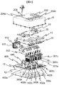
- FIG. 4 is an exploded perspective view for explaining an internal structure of a capacitor module 500.
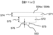
- FIG. FIG. 6 is a side sectional view for explaining the internal structure of the capacitor module 500. 6 is a side view of a positioning clip 554a attached to the capacitor module 500.
- FIG. 6 is a perspective view of a positioning clip 554a attached to the capacitor module 500.
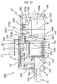
- FIG. It is sectional drawing of the power converter device 200 cut by the surface A of FIG.
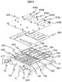
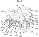
- FIG. 4 is an exploded perspective view of the driver circuit board 22 and the metal base plate 11 with the lid 8 and the control circuit board 20 removed. It is the cross-sectional perspective view cut
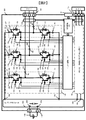
- FIG. 1 is a system diagram in which a power conversion device according to the present invention is applied to a so-called hybrid vehicle that travels using both an engine and a motor.
- the power conversion device according to the present invention can be applied not only to a hybrid vehicle but also to a so-called electric vehicle that travels only by a motor, and also as a power conversion device for driving a motor used in a general industrial machine. It can be used.
- the power conversion device according to the present invention when the power conversion device according to the present invention is applied particularly to the hybrid vehicle or the electric vehicle, excellent effects are obtained in terms of downsizing, reliability, and various other aspects. It is done.
- the power conversion device applied to the hybrid vehicle has substantially the same configuration as the power conversion device applied to the electric vehicle, and the power conversion device applied to the hybrid vehicle will be described as a representative example.
- the rotational energy generated by the engine EGN is converted into AC power by the motor generator MG2, and then the AC power is converted into DC power by the power converter 200. And the battery 136 can be charged. Transmission of mechanical energy from engine EGN to motor generator MG2 is performed by power distribution mechanism TSM.
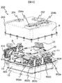
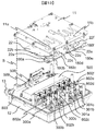
- FIG. 3 shows an exploded perspective view of a power conversion device 200 as an embodiment according to the present invention.
- the power conversion device 200 has a flow path forming body 12 that functions as a case for housing power semiconductor modules 300a to 300c and power semiconductor modules 301a to 301c and a capacitor module 500, which will be described later, and forms a flow path, and a lid 8.
- a case body may be provided separately from the flow path forming body 12 of the present embodiment, and the flow path forming body 12 may be housed in the case.
- the connector 21 is provided on the control circuit board 20 and protrudes to the outside through the first opening 202.
- the negative electrode side power line 510 and the positive electrode side power line 512 electrically connect the DC connector 138 and the capacitor module 500 and the like, and project outside through the third opening 203.
- the three surfaces that connect the first heat radiation surface 307A and the second heat radiation surface 307B that face each other constitute a surface that is sealed with a narrower width than the first heat radiation surface 307A and the second heat radiation surface 307B, and the remaining one side surface
- An insertion port 306 is formed at the bottom.
- the shape of the module case 304 does not need to be an accurate rectangular parallelepiped, and the corner may form a curved surface as shown in FIG. By using the metal case having such a shape, even when the module case 304 is inserted into a flow path through which a coolant such as water or oil flows, a seal against the coolant can be secured by the flange 304B. Intrusion into the module case 304 can be prevented with a simple configuration.
- the auxiliary module 600 side DC positive connection terminal 315C, the auxiliary module side DC negative connection terminal 319C, the auxiliary module side AC connection terminal 320C, and the auxiliary module side signal connection are connected to the auxiliary module 600 side of the connecting portion 370.
- Terminals 326U and auxiliary module side signal connection terminals 326L are arranged in a line.
- a terminal constituted by the DC positive electrode wiring 315A (including the DC positive electrode terminal 315B and the auxiliary module side DC positive electrode connection terminal 315C) and the element side DC positive electrode connection terminal 315D is referred to as a positive electrode side terminal.
- Each of the above terminals protrudes from the first sealing resin 348 and the second sealing resin 351 through the connecting portion 370, and each protruding portion from the first sealing resin 348 (element side DC positive electrode connection terminal 315D).
- Element side DC negative electrode connection terminal 319D, element side AC connection terminal 320D, element side signal connection terminal 327U and element side signal connection terminal 327L) are one surface of the first sealing resin 348 having a polyhedral shape as described above. Are lined up in a row. Further, the positive terminal and the negative terminal protrude from the second sealing resin 351 in a stacked state and extend outside the module case 304.
- the negative electrode conductor plate 505, the positive electrode conductor plate 507, the battery negative electrode side terminal 508, the battery positive electrode side terminal 509, the relay conductor portion 530, and the capacitor terminals 503a to 503f are integrally formed metal plates. And has the effect of reducing the inductance with respect to the current flowing through the series circuit 150 of the upper and lower arms.
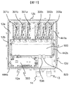
- the base plate 550 has a positioning structure with the flow path forming body 12. The position of the capacitor module 500 is determined by the positioning structure, and the base plate 550 is fixed to the flow path forming body 12.
- the metal support member 803 protrudes from the flow path forming body 12 and is connected to the flow path forming body 12.
- the metal base plate 11 is supported by the distal end portion of the support member 803.
- the flow path forming body 12 is connected to an electrical ground.
- a leakage current flow 804 indicates the direction of leakage current flowing from the driver circuit board 22 to the metal base plate 11, the support member 803, and the flow path forming body 12 in this order.
- a leakage current flow 805 indicates the direction of leakage current flowing from the control circuit board 20 to the metal base plate 11, the support member 803, and the flow path forming body 12 in this order.
Landscapes
- Engineering & Computer Science (AREA)
- Microelectronics & Electronic Packaging (AREA)
- Power Engineering (AREA)
- Inverter Devices (AREA)
Abstract
Description
電力変換装置200は、上位の制御装置から指令を受けたりあるいは上位の制御装置に状態を表すデータを送信したりするための通信用のコネクタ21を備えている。コネクタ21からの指令に基づいて、制御回路172でモータジェネレータMG1やモータジェネレータMG2、補機用モータ195の制御量を演算する。さらにモータとして運転するか発電機として運転するかを演算し、演算結果に基づいて制御パルスを発生する。ドライバ回路174や補機用パワーモジュール350のドライバ回路350Aへ、上記制御パルスを供給する。補機用パワーモジュール350は専用の制御回路を有しても良い。この場合は、コネクタ21からの指令に基づいて上記専用の制御回路が制御パルスを発生し、補機用パワーモジュール350のドライバ回路350Aへ供給する。
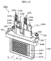
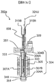
図7は、理解を助けるために、図6に示す状態からネジ309および第2封止樹脂351を取り除いたパワー半導体モジュール300aを示す図である。図7(a)は斜視図であり、図7(b)は図6(b)と同様に断面Dで切断して方向Eから見たときの断面図である。また、図7(c)はフィン305が加圧されて薄肉部304Aが変形される前の断面図を示している。
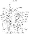
図10は、モジュール一次封止体302の組立工程を説明するための図である。
上下アームの直列回路150を構成するパワー半導体素子(IGBT328、IGBT330、ダイオード156、ダイオード166)が、図8および9に示す如く、導体板315や導体板318によって、あるいは導体板320や導体板319によって、両面から挟んで固着される。導体板315等は、その放熱面が露出した状態で第1封止樹脂348によって封止され、当該放熱面に絶縁部材333が熱圧着される。第1封止樹脂348は図8に示すように、多面体形状(ここでは略直方体形状)を有している。
このような形状の金属製のケースを用いることで、モジュールケース304を水や油などの冷媒が流れる流路内に挿入しても、冷媒に対するシールをフランジ304Bにて確保できるため、冷却媒体がモジュールケース304の内部に侵入するのを簡易な構成で防ぐことができる。また、対向した第1放熱面307Aと第2放熱面307Bに、フィン305がそれぞれ均一に形成される。さらに、第1放熱面307A及び第2放熱面307Bの外周には、厚みが極端に薄くなっている薄肉部304Aが形成されている。薄肉部304Aは、フィン305を加圧することで簡単に変形する程度まで厚みを極端に薄くしてあるため、モジュール一次封止体302が挿入された後の生産性が向上する。
補助モールド体600は、モジュール一次封止体302と接続部370において金属接合された後に、配線絶縁部608に設けられたネジ穴を貫通するネジ309によってモジュールケース304に固定される。接続部370におけるモジュール一次封止体302と補助モールド体600との金属接合には、たとえばTIG溶接などを用いることができる。
図10に示すように、直流正極側の導体板315および交流出力側の導体板320と、素子側信号接続端子327Uおよび327Lとは、共通のタイバー372に繋がれた状態で、これらが略同一平面状の配置となるように一体的に加工される。導体板315には、上アーム側のIGBT328のコレクタ電極と上アーム側のダイオード156のカソード電極が固着される。導体板320には、下アーム側のIGBT330のコレクタ電極と下アーム側のダイオード166のカソード電極が固着される。IGBT328,330およびダイオード155,166の上には、導体板318と導体板319が略同一平面状に配置される。導体板318には、上アーム側のIGBT328のエミッタ電極と上アーム側のダイオード156のアノード電極が固着される。導体板319には、下アーム側のIGBT330のエミッタ電極と下アーム側のダイオード166のアノード電極が固着される。各パワー半導体素子は、各導体板に設けられた素子固着部322に、金属接合材160を介してそれぞれ固着される。金属接合材160は、例えばはんだ材や銀シート及び微細金属粒子を含んだ低温焼結接合材、等である。
各パワー半導体素子は板状の扁平構造であり、当該パワー半導体素子の各電極は表裏面に形成されている。図10に示されるように、パワー半導体素子の各電極は、導体板315と導体板318、または導体板320と導体板319によって挟まれる。つまり、導体板315と導体板318は、IGBT328及びダイオード156を介して略平行に対向した積層配置となる。同様に、導体板320と導体板319は、IGBT330及びダイオード166を介して略平行に対向した積層配置となる。また、導体板320と導体板318は中間電極329を介して接続されている。この接続により上アーム回路と下アーム回路が電気的に接続され、上下アーム直列回路が形成される。上述したように、導体板315と導体板318の間にIGBT328及びダイオード156を挟み込むと共に、導体板320と導体板319の間にIGBT330及びダイオード166を挟み込み、導体板320と導体板318を中間電極329を介して接続する。その後、IGBT328の制御電極328Aと素子側信号接続端子327Uとをボンディングワイヤ371により接続すると共に、IGBT330の制御電極330Aと素子側信号接続端子327Lとをボンディングワイヤ371により接続する。
Claims (4)
- 直流電流を交流電流に変換するパワー半導体素子を有するパワー半導体モジュールと、
直流電圧を平滑化するコンデンサセルと、
前記パワー半導体モジュールと前記コンデンサセルとを電気的に接続するバスバーと、
前記バスバーと前記コンデンサセルとの間に配置されたベース板と、
前記コンデンサセルと前記バスバーと前記ベース板を封止する封止材と、を備え、
前記ベース板は、前記コンデンサセルから延びるコンデンサ端子を貫通させる開口部を形成する電力変換装置。 - 請求項1に記載された電力変換装置であって、
コモンモードノイズ除去用のノイズフィルタ用コンデンサセルと、
前記パワー半導体モジュールと前記コンデンサセルとを収納する金属製のケースと、を備え、
前記ベース板は、金属製の板材により形成され、
かつ前記ベース板は、接地電位にある前記ケースと電気的に接続され、
前記ノイズフィルタ用コンデンサセルの一方の電極が、前記バスバーと電気的に接続され、
前記ノイズフィルタ用コンデンサセルの他方の電極が、前記ベース板と電気的に接続される電力変換装置。 - 請求項1に記載された電力変換装置であって、
前記ケースは、冷却冷媒を流す流路を形成する流路形成体を有し、
前記ベース板は、前記流路形成体に接触して配置される電力変換装置。 - 請求項3に記載された電力変換装置であって、
絶縁部材で構成された固定部材を備え、
前記バスバーと前記ベース板との間には、絶縁部材が配置され、
前記バスバー及び前記ベース板には、前記固定部材を挿入するための貫通孔が形成され、
前記固定部材は、前記ベース板において前記バスバーが配置される側とは反対側の面と接触する係止部を有し、
前記固定部材は、前記貫通孔に挿入されると共に、前記係止部によって前記ベース板を前記バスバーと共に挟持する電力変換装置。
Priority Applications (2)
| Application Number | Priority Date | Filing Date | Title |
|---|---|---|---|
| CN201380061568.8A CN105409105B (zh) | 2012-12-26 | 2013-11-06 | 电力转换装置 |
| US14/646,935 US9999150B2 (en) | 2012-12-26 | 2013-11-06 | Electric power converter |
Applications Claiming Priority (2)
| Application Number | Priority Date | Filing Date | Title |
|---|---|---|---|
| JP2012281937A JP6097557B2 (ja) | 2012-12-26 | 2012-12-26 | 電力変換装置 |
| JP2012-281937 | 2012-12-26 |
Publications (1)
| Publication Number | Publication Date |
|---|---|
| WO2014103517A1 true WO2014103517A1 (ja) | 2014-07-03 |
Family
ID=51020616
Family Applications (1)
| Application Number | Title | Priority Date | Filing Date |
|---|---|---|---|
| PCT/JP2013/079949 Ceased WO2014103517A1 (ja) | 2012-12-26 | 2013-11-06 | 電力変換装置 |
Country Status (4)
| Country | Link |
|---|---|
| US (1) | US9999150B2 (ja) |
| JP (1) | JP6097557B2 (ja) |
| CN (1) | CN105409105B (ja) |
| WO (1) | WO2014103517A1 (ja) |
Cited By (1)
| Publication number | Priority date | Publication date | Assignee | Title |
|---|---|---|---|---|
| CN107624216A (zh) * | 2015-05-13 | 2018-01-23 | 伟肯有限公司 | 用于振荡抑制的安排 |
Families Citing this family (50)
| Publication number | Priority date | Publication date | Assignee | Title |
|---|---|---|---|---|
| US10003274B2 (en) * | 2013-09-18 | 2018-06-19 | Hitachi Automotive Systems, Ltd. | Power conversion device |
| US10131042B2 (en) | 2013-10-21 | 2018-11-20 | Milwaukee Electric Tool Corporation | Adapter for power tool devices |
| EP3101688B1 (en) * | 2014-01-27 | 2019-10-02 | Hitachi, Ltd. | Power module and manufacturing method therefor |
| DE112015002670T5 (de) * | 2014-07-29 | 2017-02-23 | Hitachi Automotive Systems, Ltd. | Leistungsumsetzungsvorrichtung |
| DE112015003244T5 (de) * | 2014-09-25 | 2017-04-13 | Hitachi Automotive Systems, Ltd. | Leistungsumsetzer |
| JP5901725B1 (ja) * | 2014-10-17 | 2016-04-13 | 三菱電機株式会社 | 防水型制御ユニットとその組立方法 |
| JP6413637B2 (ja) * | 2014-10-30 | 2018-10-31 | 株式会社オートネットワーク技術研究所 | 蓄電ユニット |
| CN104576588B (zh) * | 2015-01-20 | 2017-07-28 | 深圳希格玛和芯微电子有限公司 | 电器设备及其集成电路回路以及电路连接方法 |
| US10217683B2 (en) * | 2015-05-13 | 2019-02-26 | Mitsubishi Electric Corporation | Mounted semiconductor module with a mold resin portion |
| JP6557540B2 (ja) * | 2015-07-31 | 2019-08-07 | 日立オートモティブシステムズ株式会社 | パワーモジュール |
| EP3145286B1 (en) * | 2015-09-15 | 2019-05-01 | ABB Schweiz AG | Heat dissipation in power electronic assemblies |
| FR3043880B1 (fr) * | 2015-11-13 | 2017-12-29 | Valeo Systemes De Controle Moteur | Boitier pour un equipement electrique |
| KR102457660B1 (ko) * | 2016-01-08 | 2022-10-24 | 엘지이노텍 주식회사 | 전력 변환 장치 |
| DK3206468T3 (en) * | 2016-02-15 | 2019-04-01 | Siemens Ag | DC converter with DC voltage |
| WO2017149801A1 (ja) * | 2016-03-02 | 2017-09-08 | 三菱電機株式会社 | 電力変換装置 |
| WO2018116667A1 (ja) | 2016-12-22 | 2018-06-28 | 日立オートモティブシステムズ株式会社 | 電力変換装置 |
| JP2018107494A (ja) * | 2016-12-22 | 2018-07-05 | ルネサスエレクトロニクス株式会社 | 半導体装置及びインバータシステム |
| US10944332B2 (en) * | 2017-01-13 | 2021-03-09 | Hitachi Automotive Systems, Ltd. | Power converter with shield plate and resin support member |
| JP6866768B2 (ja) | 2017-05-29 | 2021-04-28 | 株式会社デンソー | 電力変換器 |
| JP6760203B2 (ja) * | 2017-06-05 | 2020-09-23 | 株式会社オートネットワーク技術研究所 | リレーユニット |
| JP6818661B6 (ja) * | 2017-09-13 | 2021-03-17 | 日立Astemo株式会社 | 電力変換装置 |
| JP2019067896A (ja) * | 2017-09-29 | 2019-04-25 | 日本電産エレシス株式会社 | 回路基板、および制御装置 |
| JP6557928B2 (ja) * | 2017-10-19 | 2019-08-14 | 本田技研工業株式会社 | 電力変換装置 |
| JP7035455B2 (ja) * | 2017-10-31 | 2022-03-15 | 株式会社豊田自動織機 | 車載電気機器用のカバー及びその製造方法 |
| CN110248513A (zh) * | 2018-03-07 | 2019-09-17 | 广东美的生活电器制造有限公司 | 用于食品料理机的电源板组件和具有其的食品料理机 |
| WO2019169829A1 (zh) | 2018-03-07 | 2019-09-12 | 广东美的生活电器制造有限公司 | 食品料理机和用于食品料理机的电源板组件、机座 |
| FR3080496B1 (fr) * | 2018-04-23 | 2020-05-15 | Schneider Electric Industries Sas | Module intelligent pour panneau d'armoire de brassage recevant des cables de transfert de donnees |
| US10600577B2 (en) * | 2018-04-26 | 2020-03-24 | Sf Motors, Inc. | Electric vehicle inverter module capacitors |
| DE102018110222B4 (de) * | 2018-04-27 | 2025-08-21 | Semikron Elektronik Gmbh & Co. Kg | Schaltungsanordnung zur Ansteuerung einer Leistungshalbleitereinrichtung mit zwei Schaltungsträgern und einem Kunststoffformkörper und Anordnung hiermit |
| JP7024592B2 (ja) * | 2018-05-11 | 2022-02-24 | 株式会社デンソー | 電力変換装置 |
| KR102570579B1 (ko) * | 2018-07-13 | 2023-08-24 | 엘지전자 주식회사 | 냉동기 |
| CN113826315B (zh) | 2019-05-13 | 2025-01-03 | 日立安斯泰莫株式会社 | 电力转换装置 |
| JP7088145B2 (ja) * | 2019-08-27 | 2022-06-21 | 株式会社デンソー | 電力変換回路用通電部 |
| CN111162069B (zh) * | 2019-12-23 | 2022-04-01 | 美的集团(上海)有限公司 | 一种智能功率模块及其制备方法 |
| US11527357B2 (en) | 2020-04-10 | 2022-12-13 | Hamilton Sundstrand Corporation | Busbar with tailored perforation sizes to provide thermal path |
| KR102870308B1 (ko) * | 2020-08-05 | 2025-10-15 | 엘지이노텍 주식회사 | 방열모듈 및 이를 포함하는 전자장치 |
| JP7545298B2 (ja) * | 2020-11-13 | 2024-09-04 | 株式会社日立製作所 | 電力変換装置 |
| JP7113937B1 (ja) * | 2021-04-15 | 2022-08-05 | 三菱電機株式会社 | 電力変換装置 |
| JP7192918B1 (ja) | 2021-06-14 | 2022-12-20 | 株式会社明電舎 | バスバー放熱構造及びインバータ装置 |
| JP7366082B2 (ja) | 2021-06-18 | 2023-10-20 | 三菱電機株式会社 | 電力変換装置 |
| JP7627356B2 (ja) * | 2021-10-01 | 2025-02-05 | 三菱自動車工業株式会社 | 車両駆動装置 |
| EP4410577B1 (en) * | 2021-10-01 | 2026-04-22 | Mitsubishi Jidosha Kogyo Kabushiki Kaisha | Vehicle drive device |
| EP4412074B1 (en) * | 2021-10-01 | 2026-01-21 | Mitsubishi Jidosha Kogyo Kabushiki Kaisha | Vehicle drive device |
| JP7721788B2 (ja) * | 2022-02-22 | 2025-08-12 | Astemo株式会社 | 電力変換装置 |
| JP7809017B2 (ja) * | 2022-06-02 | 2026-01-30 | 三菱電機株式会社 | 電力変換装置 |
| JP2024006754A (ja) * | 2022-07-04 | 2024-01-17 | トヨタ自動車株式会社 | パワーコントロールユニット |
| US12363873B2 (en) | 2022-08-31 | 2025-07-15 | Ford Global Technologies, Llc | Electrified vehicle inductor cooling system |
| JP2024112645A (ja) * | 2023-02-08 | 2024-08-21 | 株式会社デンソー | 電力変換装置、および、yコンデンサ |
| CN119489763A (zh) * | 2023-08-17 | 2025-02-21 | 宁德时代新能源科技股份有限公司 | 配电装置、电池及用电设备 |
| US20250300569A1 (en) * | 2024-03-20 | 2025-09-25 | Ford Global Technologies, Llc | Power module for electrified vehicle |
Citations (3)
| Publication number | Priority date | Publication date | Assignee | Title |
|---|---|---|---|---|
| JP2002016202A (ja) * | 2000-06-29 | 2002-01-18 | Denso Corp | インバータ装置 |
| JP2011217550A (ja) * | 2010-04-01 | 2011-10-27 | Hitachi Automotive Systems Ltd | 電力変換装置 |
| JP2012249480A (ja) * | 2011-05-31 | 2012-12-13 | Hitachi Automotive Systems Ltd | 電力変換装置 |
Family Cites Families (6)
| Publication number | Priority date | Publication date | Assignee | Title |
|---|---|---|---|---|
| JP2006174572A (ja) * | 2004-12-15 | 2006-06-29 | Mitsubishi Electric Corp | 電力変換装置 |
| JP4434181B2 (ja) | 2006-07-21 | 2010-03-17 | 株式会社日立製作所 | 電力変換装置 |
| JP4751810B2 (ja) * | 2006-11-02 | 2011-08-17 | 日立オートモティブシステムズ株式会社 | 電力変換装置 |
| JP4905254B2 (ja) * | 2007-05-25 | 2012-03-28 | トヨタ自動車株式会社 | コンデンサ一体バスバーの製造方法 |
| JP4452953B2 (ja) | 2007-08-09 | 2010-04-21 | 日立オートモティブシステムズ株式会社 | 電力変換装置 |
| JP5099243B2 (ja) * | 2010-04-14 | 2012-12-19 | 株式会社デンソー | 半導体モジュール |
-
2012
- 2012-12-26 JP JP2012281937A patent/JP6097557B2/ja active Active
-
2013
- 2013-11-06 CN CN201380061568.8A patent/CN105409105B/zh active Active
- 2013-11-06 WO PCT/JP2013/079949 patent/WO2014103517A1/ja not_active Ceased
- 2013-11-06 US US14/646,935 patent/US9999150B2/en active Active
Patent Citations (3)
| Publication number | Priority date | Publication date | Assignee | Title |
|---|---|---|---|---|
| JP2002016202A (ja) * | 2000-06-29 | 2002-01-18 | Denso Corp | インバータ装置 |
| JP2011217550A (ja) * | 2010-04-01 | 2011-10-27 | Hitachi Automotive Systems Ltd | 電力変換装置 |
| JP2012249480A (ja) * | 2011-05-31 | 2012-12-13 | Hitachi Automotive Systems Ltd | 電力変換装置 |
Cited By (3)
| Publication number | Priority date | Publication date | Assignee | Title |
|---|---|---|---|---|
| CN107624216A (zh) * | 2015-05-13 | 2018-01-23 | 伟肯有限公司 | 用于振荡抑制的安排 |
| US10433448B2 (en) | 2015-05-13 | 2019-10-01 | Vacon Oy | Arrangement for oscillation dampening |
| CN107624216B (zh) * | 2015-05-13 | 2020-04-03 | 伟肯有限公司 | 电力电子设备 |
Also Published As
| Publication number | Publication date |
|---|---|
| US20150305188A1 (en) | 2015-10-22 |
| CN105409105B (zh) | 2018-05-29 |
| CN105409105A (zh) | 2016-03-16 |
| JP6097557B2 (ja) | 2017-03-15 |
| US9999150B2 (en) | 2018-06-12 |
| JP2014128084A (ja) | 2014-07-07 |
Similar Documents
| Publication | Publication Date | Title |
|---|---|---|
| JP6097557B2 (ja) | 電力変換装置 | |
| JP5789576B2 (ja) | 電力変換装置 | |
| JP5738817B2 (ja) | 電力変換装置 | |
| JP6072492B2 (ja) | コンデンサモジュール及び電力変換装置 | |
| JP5846854B2 (ja) | 一体型電力変換装置及びそれに用いられるdcdcコンバータ装置 | |
| JP5744999B2 (ja) | パワー半導体装置、パワー半導体装置の製造方法 | |
| JP5506749B2 (ja) | 電力変換装置 | |
| JP5422466B2 (ja) | 電力変換装置 | |
| JP5651552B2 (ja) | 電力変換装置 | |
| CN103703667B (zh) | 电力变换装置 | |
| JP2012139014A (ja) | 車両用電力変換装置 | |
| WO2012165341A1 (ja) | 電力変換装置 | |
| JP6035615B2 (ja) | 電力変換装置 | |
| JP5378293B2 (ja) | パワーモジュール及びそれを用いた電力変換装置 | |
| JP5978324B2 (ja) | 電力変換装置 | |
| JP5966065B2 (ja) | 電力変換装置 | |
| JP2014023327A (ja) | パワー半導体モジュール及びそれを用いた電力変換装置 | |
| JP2014113051A (ja) | 電力変換装置 |
Legal Events
| Date | Code | Title | Description |
|---|---|---|---|
| WWE | Wipo information: entry into national phase |
Ref document number: 201380061568.8 Country of ref document: CN |
|
| 121 | Ep: the epo has been informed by wipo that ep was designated in this application |
Ref document number: 13867847 Country of ref document: EP Kind code of ref document: A1 |
|
| WWE | Wipo information: entry into national phase |
Ref document number: 14646935 Country of ref document: US |
|
| NENP | Non-entry into the national phase |
Ref country code: DE |
|
| 122 | Ep: pct application non-entry in european phase |
Ref document number: 13867847 Country of ref document: EP Kind code of ref document: A1 |