WO2014061085A1 - 低温ソルダペーストのはんだ付け方法 - Google Patents
低温ソルダペーストのはんだ付け方法 Download PDFInfo
- Publication number
- WO2014061085A1 WO2014061085A1 PCT/JP2012/076631 JP2012076631W WO2014061085A1 WO 2014061085 A1 WO2014061085 A1 WO 2014061085A1 JP 2012076631 W JP2012076631 W JP 2012076631W WO 2014061085 A1 WO2014061085 A1 WO 2014061085A1
- Authority
- WO
- WIPO (PCT)
- Prior art keywords
- solder
- solder paste
- composition
- preform
- snbi
- Prior art date
Links
Images


Classifications
-
- B—PERFORMING OPERATIONS; TRANSPORTING
- B23—MACHINE TOOLS; METAL-WORKING NOT OTHERWISE PROVIDED FOR
- B23K—SOLDERING OR UNSOLDERING; WELDING; CLADDING OR PLATING BY SOLDERING OR WELDING; CUTTING BY APPLYING HEAT LOCALLY, e.g. FLAME CUTTING; WORKING BY LASER BEAM
- B23K1/00—Soldering, e.g. brazing, or unsoldering
- B23K1/0008—Soldering, e.g. brazing, or unsoldering specially adapted for particular articles or work
- B23K1/0016—Brazing of electronic components
-
- B—PERFORMING OPERATIONS; TRANSPORTING
- B23—MACHINE TOOLS; METAL-WORKING NOT OTHERWISE PROVIDED FOR
- B23K—SOLDERING OR UNSOLDERING; WELDING; CLADDING OR PLATING BY SOLDERING OR WELDING; CUTTING BY APPLYING HEAT LOCALLY, e.g. FLAME CUTTING; WORKING BY LASER BEAM
- B23K35/00—Rods, electrodes, materials, or media, for use in soldering, welding, or cutting
- B23K35/02—Rods, electrodes, materials, or media, for use in soldering, welding, or cutting characterised by mechanical features, e.g. shape
- B23K35/0222—Rods, electrodes, materials, or media, for use in soldering, welding, or cutting characterised by mechanical features, e.g. shape for use in soldering, brazing
- B23K35/0244—Powders, particles or spheres; Preforms made therefrom
- B23K35/025—Pastes, creams, slurries
-
- B—PERFORMING OPERATIONS; TRANSPORTING
- B23—MACHINE TOOLS; METAL-WORKING NOT OTHERWISE PROVIDED FOR
- B23K—SOLDERING OR UNSOLDERING; WELDING; CLADDING OR PLATING BY SOLDERING OR WELDING; CUTTING BY APPLYING HEAT LOCALLY, e.g. FLAME CUTTING; WORKING BY LASER BEAM
- B23K35/00—Rods, electrodes, materials, or media, for use in soldering, welding, or cutting
- B23K35/22—Rods, electrodes, materials, or media, for use in soldering, welding, or cutting characterised by the composition or nature of the material
- B23K35/24—Selection of soldering or welding materials proper
- B23K35/26—Selection of soldering or welding materials proper with the principal constituent melting at less than 400 degrees C
- B23K35/262—Sn as the principal constituent
-
- B—PERFORMING OPERATIONS; TRANSPORTING
- B23—MACHINE TOOLS; METAL-WORKING NOT OTHERWISE PROVIDED FOR
- B23K—SOLDERING OR UNSOLDERING; WELDING; CLADDING OR PLATING BY SOLDERING OR WELDING; CUTTING BY APPLYING HEAT LOCALLY, e.g. FLAME CUTTING; WORKING BY LASER BEAM
- B23K35/00—Rods, electrodes, materials, or media, for use in soldering, welding, or cutting
- B23K35/22—Rods, electrodes, materials, or media, for use in soldering, welding, or cutting characterised by the composition or nature of the material
- B23K35/24—Selection of soldering or welding materials proper
- B23K35/26—Selection of soldering or welding materials proper with the principal constituent melting at less than 400 degrees C
- B23K35/264—Bi as the principal constituent
-
- B—PERFORMING OPERATIONS; TRANSPORTING
- B23—MACHINE TOOLS; METAL-WORKING NOT OTHERWISE PROVIDED FOR
- B23K—SOLDERING OR UNSOLDERING; WELDING; CLADDING OR PLATING BY SOLDERING OR WELDING; CUTTING BY APPLYING HEAT LOCALLY, e.g. FLAME CUTTING; WORKING BY LASER BEAM
- B23K35/00—Rods, electrodes, materials, or media, for use in soldering, welding, or cutting
- B23K35/40—Making wire or rods for soldering or welding
-
- C—CHEMISTRY; METALLURGY
- C22—METALLURGY; FERROUS OR NON-FERROUS ALLOYS; TREATMENT OF ALLOYS OR NON-FERROUS METALS
- C22C—ALLOYS
- C22C12/00—Alloys based on antimony or bismuth
-
- C—CHEMISTRY; METALLURGY
- C22—METALLURGY; FERROUS OR NON-FERROUS ALLOYS; TREATMENT OF ALLOYS OR NON-FERROUS METALS
- C22C—ALLOYS
- C22C13/00—Alloys based on tin
- C22C13/02—Alloys based on tin with antimony or bismuth as the next major constituent
-
- H—ELECTRICITY
- H05—ELECTRIC TECHNIQUES NOT OTHERWISE PROVIDED FOR
- H05K—PRINTED CIRCUITS; CASINGS OR CONSTRUCTIONAL DETAILS OF ELECTRIC APPARATUS; MANUFACTURE OF ASSEMBLAGES OF ELECTRICAL COMPONENTS
- H05K3/00—Apparatus or processes for manufacturing printed circuits
- H05K3/30—Assembling printed circuits with electric components, e.g. with resistor
- H05K3/32—Assembling printed circuits with electric components, e.g. with resistor electrically connecting electric components or wires to printed circuits
- H05K3/34—Assembling printed circuits with electric components, e.g. with resistor electrically connecting electric components or wires to printed circuits by soldering
- H05K3/3457—Solder materials or compositions; Methods of application thereof
- H05K3/3463—Solder compositions in relation to features of the printed circuit board or the mounting process
-
- H—ELECTRICITY
- H05—ELECTRIC TECHNIQUES NOT OTHERWISE PROVIDED FOR
- H05K—PRINTED CIRCUITS; CASINGS OR CONSTRUCTIONAL DETAILS OF ELECTRIC APPARATUS; MANUFACTURE OF ASSEMBLAGES OF ELECTRICAL COMPONENTS
- H05K2203/00—Indexing scheme relating to apparatus or processes for manufacturing printed circuits covered by H05K3/00
- H05K2203/04—Soldering or other types of metallurgic bonding
-
- H—ELECTRICITY
- H05—ELECTRIC TECHNIQUES NOT OTHERWISE PROVIDED FOR
- H05K—PRINTED CIRCUITS; CASINGS OR CONSTRUCTIONAL DETAILS OF ELECTRIC APPARATUS; MANUFACTURE OF ASSEMBLAGES OF ELECTRICAL COMPONENTS
- H05K2203/00—Indexing scheme relating to apparatus or processes for manufacturing printed circuits covered by H05K3/00
- H05K2203/12—Using specific substances
-
- H—ELECTRICITY
- H05—ELECTRIC TECHNIQUES NOT OTHERWISE PROVIDED FOR
- H05K—PRINTED CIRCUITS; CASINGS OR CONSTRUCTIONAL DETAILS OF ELECTRIC APPARATUS; MANUFACTURE OF ASSEMBLAGES OF ELECTRICAL COMPONENTS
- H05K3/00—Apparatus or processes for manufacturing printed circuits
- H05K3/30—Assembling printed circuits with electric components, e.g. with resistor
- H05K3/32—Assembling printed circuits with electric components, e.g. with resistor electrically connecting electric components or wires to printed circuits
- H05K3/34—Assembling printed circuits with electric components, e.g. with resistor electrically connecting electric components or wires to printed circuits by soldering
- H05K3/3457—Solder materials or compositions; Methods of application thereof
- H05K3/3485—Applying solder paste, slurry or powder
Definitions
- the present invention relates to a soldering method for a printed circuit board using a lead-free solder containing Bi, particularly a low-temperature solder paste in the vicinity of a SnBi eutectic called a low-temperature solder.
- a printed circuit board with electronic components soldered as a main circuit is used in electrical products such as home appliances, audio equipment, and computers, and Sn-37% by mass (this time, Indicating mass%) Sn-Pb solder with Pb composition has been used.
- Sn-Pb solder with Pb composition has been used.
- Pb may be dissolved from the discarded printed circuit board to contaminate groundwater. Due to such environmental problems, lead-free solder used for printed circuit boards has been promoted for more than ten years, and most electrical products are now made of lead-free solder.
- a conventionally used Sn—Pb solder has a melting point of 183 ° C. and can be soldered at a low working temperature. When the soldering work temperature is low, it is not necessary to consider the heat resistance of the electronic parts used for soldering, and it was possible to use electronic parts with low heat resistance such as plastic connectors.
- Sn-Ag-Cu-based lead-free solders such as Sn-3.0% Ag-0.5% Cu are currently used as the mainstream lead-free solder.
- Sn-Ag-Cu-based lead-free solder has good characteristics that it is more resistant to temperature cycling than conventional Sn-Pb solder, but its melting temperature is about 220 ° C compared to conventional Sn-Pb solder.
- solder alloy Sn-58% Bi solder (melting temperature 139) that has been used as a low-temperature solder. ° C) or Sn-58% Bi with a small amount of Ag added, it has been studied to use a low-temperature solder such as a solder alloy whose strength and elongation are improved (Japanese Patent Laid-Open No. 8-252688, Patent Document 1). It was.
- solder paste of Sn—Pb composition is applied to the joint surface of the substrate, and solder balls containing In are placed in contact with the paste, and the paste and A method of relaxing the shear stress by heating the reform (Japanese Patent Laid-Open No. 8-116169, Patent Document 2) is disclosed.
- solder which has a low melting temperature
- solder composition close to the Sn-Bi eutectic solder composition having a Sn-57% Bi composition is mainly used as the reflow solder.
- solder composition close to the SnBi eutectic solder composition is improved in strength as in Patent Document 1, it has brittle characteristics, so it is used for small electronic devices such as portable devices and laptop computers. In such a case, since the drop impact resistance is low when a small electronic device is dropped, the printed circuit board and the soldering surface are often peeled off and destroyed.
- the present invention has been developed to address such problems.
- the problem to be solved and used by the present invention is that a solder paste having a solder composition close to the SnBi eutectic solder composition is used for soldering a printed circuit board of a small electronic device in order to reduce electric energy and use an electronic component having low heat resistance. Even in such a case, it is to obtain a solder joint having a drop impact resistance similar to that of SnAgCu solder currently used as lead-free solder.
- the present inventors use a solder paste having a solder composition close to the SnBi eutectic solder composition for soldering to print on the land of the printed circuit board.
- Solder of Sn-Ag, Sn-Cu, Sn-Ag-Cu when reflow soldering with a solder composition preform of Sn-Ag, Sn-Cu, Sn-Ag-Cu on the printed solder paste It was found that even if a preform having a composition was placed, soldering was possible under the reflow conditions of the solder paste alone, and the present invention was completed.
- the present invention simultaneously supplies one or more preforms selected from Sn-Ag, Sn-Cu, and Sn-Ag-Cu solder compositions during soldering using a SnBi-based low-temperature solder paste.
- one or more solder compositions selected from Sn-Ag, Sn-Cu, and Sn-Ag-Cu solder compositions are diffused into the solder paste in the SnBi-based low-temperature solder.
- Patent Document 2 it has been known to reinforce the weak point of solder by using a mixture of different solder compositions.
- the reflow temperature at this time is determined in consideration of a solder alloy having a high melting point, and it has not been considered that soldering is possible under the same reflow conditions as low-temperature solder. For this reason, reflow is performed at a temperature higher than that of low-temperature solder, and it is considered that electronic components with low heat resistance and low heat resistance can be used by mixing different solder compositions. There wasn't.
- the solder joint after soldering has Sn-Bi. Since a solder composition with a low melting point of -In eutectic of 64 ° C. appears, the electronic device cannot be used because it is left in the field or the electronic device is heated to remelt the joint.
- the present invention is a soldering method based on a completely new concept in that respect, and the present invention exhibits its effect depending on the solder composition of the solder paste, the solder composition of the preform, and the ratio of the solder paste to the preform.
- soldering method of the present invention a solder paste having a solder composition close to the SnBi eutectic solder composition for soldering a printed circuit board of a small electronic device in order to reduce electric energy and use an electronic component having low heat resistance Even in the case of using, it is possible to obtain a solder joint having the same drop impact resistance as that of SnAgCu solder currently used as lead-free solder.
- SnBi solder paste used in the present invention is Sn-Bi solder close to SnBi eutectic, and Sn-Bi-Ag solder powder in which Ag is added as a strength-adding element to Sn-Bi solder and flux mixed with solder paste Is used.
- the solder composition of the solder paste used in the soldering method of the present invention uses Bi of 35% or more and 60% or less, the remaining Sn solder, and Sn-Bi-Ag solder powder to which 3% or less of Ag is added. It is done. More preferably, it is a solder powder in which Bi is 40% or more and 58% or less and the balance is Sn, and the addition of Ag is preferably 1% or less.
- the preform added to the solder paste used in the soldering method of the present invention is a preform having a Sn-Ag, Sn-Cu, or Sn-Ag-Cu composition.
- the preform of Sn-Ag composition is preferably a preform having a residual Sn composition with an Ag of 0.3% or more and less than 4.0%.
- the preform of Sn-Cu composition has a Cu content of 0.3% or more, 1 A preform having a residual Sn composition of 2% or less is preferred.
- the preform having the Sn—Ag—Cu composition is preferably a preform having an Ag of 0.3% to 4.0%, Cu of 0.3% to 1.2%, and a residual Sn composition. More preferably, a preform having a composition of Ag of 1.0% or more and 3.0 or less, Cu of 0.5% or more and 0.8% or less, and remaining Sn is used.
- the amount of Sn, Ag, Cu, etc. entering the SnBi solder composition varies depending on the amount of preform added to the solder paste, and therefore the drop impact resistance characteristics after reflow vary.
- the amount of the preform added by the soldering method of the present invention is less than 0.7% by mass of the amount of the solder paste, the amount of Sn, Ag, Cu, etc. entering the SnBi solder composition is reduced, and the preform is reduced. The effect of adding reform is not obtained.
- the amount of preform added exceeds 75% of the amount of solder paste, the melting point of the mixed solder becomes too high, and reflow under the same reflow conditions as the SnBi solder composition becomes impossible.
- the amount of the preform added to the solder paste of the present invention is preferably 0.7% by mass or more and 75% or less of the amount of the solder paste. More preferably, it is 0.8 mass% or more and 2.0 mass%.
- the preform was placed on the land on which the SnBi solder paste was printed, and reflow soldering was performed under the heating conditions of a normal SnBi solder paste. After allowing to cool to room temperature, a drop impact test was performed, and the number of times the soldered part was destroyed was measured.
- the test method of the drop impact test was performed according to the following procedure.
- As the evaluation substrate a glass epoxy substrate (FR-4) having a size of 30 ⁇ 120 mm and a thickness of 0.8 mm was used. In the drop test, both ends of the substrate were fixed using a dedicated jig at a position where the evaluation substrate was lifted 10 mm from the pedestal.
- a solder paste using a solder powder of Sn-57Bi-1Ag composition was printed on a printed circuit board as shown in FIG. 5 on a copper land having a land size of 0.5 mm ⁇ .
- soldering state after reflow was confirmed, and it was confirmed that soldering was possible under normal low-temperature solder reflow conditions.
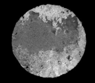
- the result of the check is that the solder component of the solder paste and the solder component of the preform are mixed together in one preform and cannot be distinguished from each other, but the solder is squared and the preform component is mixed in two preforms. You can see that they do not match.
Abstract
Description
このような環境上の問題から、十数年前からプリント基板に用いられるはんだの鉛フリー化が進められており、現在はほとんどの電気製品が鉛フリーはんだによって作られている。
それに対して現在主流の鉛フリーはんだは、Sn-3.0%Ag-0.5%CuなどのSn-Ag-Cu系鉛フリーはんだが用いられている。Sn-Ag-Cu系鉛フリーはんだは、従来のSn-Pbはんだに比較して温度サイクル特性に強いという良好な特性を有するが、溶融温度が約220℃と従来のSn-Pbはんだに比較して約40℃高く、耐熱性の低い電子部品は使用できなかった。
鉛フリーはんだが開発された当初は、電子部品も耐熱性を有しない物が多かったので、開発されたはんだ合金は、従来から低温はんだとして使用されてきたSn-58%Biはんだ(溶融温度139℃)やSn-58%BiにAgを少量添加することで強度及び延びを向上させたはんだ合金(特開平8-252688号公報、特許文献1)などの低温はんだを使用することが検討されてきた。
しかし、これらのSn-Bi系はんだ合金は、携帯電話やノートパソコンなどの小型電子機器に使用した場合、小型電子機器を落としたときにはんだ接合部界面から破壊される落下衝撃破壊に弱い事が知られており、これらの電子機器用のはんだには使用されることがなかった。
また、鉛フリーはんだでのリフローはんだ付けに耐えることができない耐熱性の低い半導体等の電子部品は存在し続けており、これらの電子部品ははんだ鏝等の後付で取り付けられていた。
しかし、SnBi共晶はんだ組成に近いはんだ組成は、特許文献1のようにその強度を改善したものであっても、脆い特性を有しているため携帯機器やノートパソコンなどの小型電子機器に使用した場合、小型電子機器を落としたときに耐落下衝撃性が低いので、プリント基板とはんだ付け面が界面剥離して破壊されてしまうことが多かった。
本発明が解決使用とする課題は、電力量の削減や耐熱性の低い電子部品を用いるために、小型電子機器のプリント基板のはんだ付けにSnBi共晶はんだ組成に近いはんだ組成のソルダペーストを用いた場合でも、現在鉛フリーはんだとして使用されているSnAgCuはんだと同様の耐落下衝撃特性を有するはんだ継ぎ手を得ることである。
本発明は、SnBi系低温はんだのソルダペーストを用いたはんだ付け時に、Sn-Ag、Sn-Cu、Sn-Ag-Cuのはんだ組成から選択された1種以上のプリフォームを同時に供給することにより、SnBi系低温はんだ中に、Sn-Ag、Sn-Cu、Sn-Ag-Cuのはんだ組成から選択された1種以上のはんだ組成をソルダペースト中に拡散させるはんだ付け方法である。
また、特許文献2が開示しているIn-10%Ags組成の鉛フリープリフォームをSn-Bi共晶はんだ組成に近いはんだ組成のソルダペーストに用いると、はんだ付け後のはんだ継ぎ手にSn-Bi-In共晶の64℃という低融点のはんだ組成が現れてしまうので、電子機器を野外に放置したり、電子機器が加熱しただけで継ぎ手が再溶融して使えなかった。
本発明はその点で全く新しい考え方によるはんだ付け方法であり、本発明は、ソルダペーストのはんだ組成、プリフォームのはんだ組成、ソルダペーストとプリフォームの比率によってその効果を現す。
1.ソルダペーストがプリント基板のランドとリフローはんだ付けされると、SnBiはんだ中のBiは、はんだ全体に拡散してBiリッチ層を形成する。(図1)
単にSn-Biはんだのソルダペーストをプリント基板にはんだ付けしただけでは、はんだフィレットにBiリッチ層が多く現れるので、力を加えると硬くてもろいBiリッチ部からクラックが入り、はんだフィレットが破壊される。(図2)
2.ソルダペーストとプリント基板のランドをはんだ付け時にソルダペーストにSn-Ag、Sn-Cu、Sn-Ag-Cu組成のプリフォームを加えると、SnBiはんだ中にSn-Ag、Sn-Cu、Sn-Ag-Cu組成が拡散して、Biリッチ層を形成しない。(図3)
ソルダペーストとプリント基板のランドをはんだ付け時にソルダペーストにSn-Ag、Sn-Cu、Sn-Ag-Cu組成のプリフォームを加えたはんだ付けに力を加えると、はんだフィレット部分からは破壊されずに、プリント基板のランドとはんだ接合部に形成された金属間化合物層から破壊される。(図4)
従って、本発明のソルダペーストに添加するプリフォームの量は、ソルダペーストの量の0.7質量%以上、75%以下が好ましい。より好ましくは、0.8質量%以上、2.0質量%の場合である。
常温まで放冷後、落下衝撃試験を行い、はんだ付け部が破壊されるのでの回数を測定した。落下衝撃試験の試験方法は、次のような手順で行った。
評価基板は、サイズ30×120mm、厚み0.8mmのガラスエポキシ基板(FR-4)を使用した。
落下試験は、評価基板を台座から10mm浮かせた位置に専用治具を用いて基板両端を固定させた。JEDEC(Joint Electron Device Engineering Council、半導体技術協会)の規格に準じて、加速度1500Gの衝撃を繰り返し加え、初期抵抗値から1.5倍以上抵抗値が増加した時点を破断とみなし、落下回数を記録した。
結果は表1に記載する。

また、落下衝撃試験結果においても、SnBi系低温ソルダペーストにSn-Ag、Sn-Cu、Sn-Ag-Cu組成のプリフォームを添加したものと添加しないものを比較すると、Sn-Ag、Sn-Cu、Sn-Ag-Cu組成のプリフォームが優れていることが解る。また、同じプリフォームの添加でも、Sn-5Sb組成のプリフォームの添加では、耐落下衝撃性が改善させない。
この試験は、Sn-Bi組成のソルダペーストと添加したプリフォームとの量を確認する物で、プリフォームを1個では、ソルダペースト重量:プリフォーム重量=1.1.6である。プリフォームを2枚では、同じく1.3.2となる。
確認結果は、プリフォーム1枚ではソルダペーストのはんだ成分とプリフォームのはんだ成分が混じり合い、区別が付かなくなっているのに対して、プリフォーム2枚でははんだが角張って、プリフォーム成分が混じり合っていないのが確認できる。
2. 銅ランド
Claims (4)
- SnBi系低温はんだのソルダペーストを用いたはんだ付け方法において、、Sn-Ag、Sn-Cu、Sn-Ag-Cuのはんだ組成から選択された1種以上のプリフォームを印刷されたソルダペースト上に供給することにより、SnBi系低温はんだ中に、Sn-Ag、Sn-Cu、Sn-Ag-Cuのはんだ組成から選択された1種以上のはんだ組成をソルダペースト中に拡散させるはんだ付け方法。
- 前記、SnBi系低温はんだのソルダペーストのはんだ付け方法は、Biが35%以上、60%以下、残Snの組成のはんだ粉末及び、さらにその組成にAgを3%以下添加した組成のはんだ粉末とフラックスを混和したものからなる低温ソルダペーストを使用することを特徴とする請求項1に記載のソルダペーストのはんだ付け方法。
- 前記、Sn-Ag、Sn-Cu、Sn-Ag-Cuのはんだ組成から選択された1種以上のプリフォームは、Agが0.3質量%以上、4.0質量%以下、残Sn組成のプリフォーム、Cuが0.3質量%以上、1.2質量%以下、残Sn組成のプリフォーム、Agが0.3質量%以上、4.0質量%以下、Cuが0.3質量%以上、1.2質量%以下、残Sn組成のプリフォームから選択された1種以上のプリフォームであることを特徴とする請求項1又は2に記載のソルダペーストのはんだ付け方法。
- 前記、ソルダペーストに添加するプリフォームの量がソルダペーストの量の0.7質量%以上、75質量%以下の量のプリフォームをソルダペーストに添加することを特徴とする請求項1乃至3に記載のソルダペーストのはんだ付け方法。
Priority Applications (6)
| Application Number | Priority Date | Filing Date | Title |
|---|---|---|---|
| JP2014541836A JP5796685B2 (ja) | 2012-10-15 | 2012-10-15 | 低温ソルダペーストのはんだ付け方法 |
| US14/435,333 US9402321B2 (en) | 2012-10-15 | 2012-10-15 | Soldering method using a low-temperature solder paste |
| PCT/JP2012/076631 WO2014061085A1 (ja) | 2012-10-15 | 2012-10-15 | 低温ソルダペーストのはんだ付け方法 |
| CN201280076433.4A CN104737630B (zh) | 2012-10-15 | 2012-10-15 | 低温焊膏的焊接方法 |
| EP12886725.6A EP2908612B1 (en) | 2012-10-15 | 2012-10-15 | Soldering method for low-temperature solder paste |
| KR1020157007749A KR101587076B1 (ko) | 2012-10-15 | 2012-10-15 | 저온 솔더 페이스트의 납땜 방법 |
Applications Claiming Priority (1)
| Application Number | Priority Date | Filing Date | Title |
|---|---|---|---|
| PCT/JP2012/076631 WO2014061085A1 (ja) | 2012-10-15 | 2012-10-15 | 低温ソルダペーストのはんだ付け方法 |
Publications (1)
| Publication Number | Publication Date |
|---|---|
| WO2014061085A1 true WO2014061085A1 (ja) | 2014-04-24 |
Family
ID=50487675
Family Applications (1)
| Application Number | Title | Priority Date | Filing Date |
|---|---|---|---|
| PCT/JP2012/076631 WO2014061085A1 (ja) | 2012-10-15 | 2012-10-15 | 低温ソルダペーストのはんだ付け方法 |
Country Status (6)
| Country | Link |
|---|---|
| US (1) | US9402321B2 (ja) |
| EP (1) | EP2908612B1 (ja) |
| JP (1) | JP5796685B2 (ja) |
| KR (1) | KR101587076B1 (ja) |
| CN (1) | CN104737630B (ja) |
| WO (1) | WO2014061085A1 (ja) |
Cited By (1)
| Publication number | Priority date | Publication date | Assignee | Title |
|---|---|---|---|---|
| WO2021131620A1 (ja) | 2019-12-27 | 2021-07-01 | 昭和電工マテリアルズ株式会社 | 接続構造体及び接続構造体の製造方法 |
Families Citing this family (7)
| Publication number | Priority date | Publication date | Assignee | Title |
|---|---|---|---|---|
| CN108098092A (zh) * | 2017-12-21 | 2018-06-01 | 成都川美新技术股份有限公司 | 一种采用焊锡膏对射频基板与壳体进行烧结的方法 |
| US20200398382A1 (en) * | 2018-04-13 | 2020-12-24 | Senju Metal Industry Co., Ltd. | Solder paste |
| CN110549030A (zh) * | 2019-08-23 | 2019-12-10 | 江苏太阳科技股份有限公司 | 一种用于hit异质结的光伏焊带的低温焊料及制备方法 |
| KR102371636B1 (ko) * | 2020-04-23 | 2022-03-07 | 제엠제코(주) | 양면 기판 반도체 제조 방법 |
| DE102021103360A1 (de) | 2021-02-05 | 2022-08-11 | Few Fahrzeugelektrik Werk Gmbh & Co. Kg | Verfahren zur Herstellung einer Vorverzinnungsanordnung und derartige Vorverzinnungsanordnung |
| CN113319454B (zh) * | 2021-04-29 | 2022-08-23 | 中国电子科技集团公司第二十九研究所 | 一种表贴自带固态焊料连接器焊端焊料预置方法 |
| WO2022261130A1 (en) * | 2021-06-11 | 2022-12-15 | Indium Corporation | High reliability lead-free solder pastes with mixed solder alloy powders |
Citations (5)
| Publication number | Priority date | Publication date | Assignee | Title |
|---|---|---|---|---|
| JPH08116169A (ja) | 1994-09-29 | 1996-05-07 | Motorola Inc | 合金はんだ接続アセンブリおよび接続方法 |
| JPH08252688A (ja) | 1995-03-17 | 1996-10-01 | Fujitsu Ltd | 低温接合用はんだ合金、これを用いた電子機器およびその製造方法 |
| JP2000307228A (ja) * | 1999-04-22 | 2000-11-02 | Mitsubishi Electric Corp | 鉛を含まないはんだ接合方法及びこれによって製造された電子モジュール |
| JP2004056065A (ja) * | 2002-05-30 | 2004-02-19 | Hitachi Ltd | 電子基板の製造方法 |
| JP2011253853A (ja) * | 2010-05-31 | 2011-12-15 | Sony Corp | はんだ接合方法 |
Family Cites Families (36)
| Publication number | Priority date | Publication date | Assignee | Title |
|---|---|---|---|---|
| US5320272A (en) * | 1993-04-02 | 1994-06-14 | Motorola, Inc. | Tin-bismuth solder connection having improved high temperature properties, and process for forming same |
| JPH06296080A (ja) * | 1993-04-08 | 1994-10-21 | Sony Corp | 電子部品実装基板及び電子部品実装方法 |
| US6896172B2 (en) * | 2000-08-22 | 2005-05-24 | Senju Metal Industry Co., Ltd. | Lead-free solder paste for reflow soldering |
| JP4438974B2 (ja) * | 2000-10-05 | 2010-03-24 | 千住金属工業株式会社 | ソルダペ−スト |
| US6926849B2 (en) * | 2000-11-29 | 2005-08-09 | Senju Metal Industry Co., Ltd. | Solder paste |
| JP2003234433A (ja) * | 2001-10-01 | 2003-08-22 | Matsushita Electric Ind Co Ltd | 半導体装置、半導体装置の実装方法、ならびに実装体およびその製造方法 |
| US6805974B2 (en) * | 2002-02-15 | 2004-10-19 | International Business Machines Corporation | Lead-free tin-silver-copper alloy solder composition |
| CN1445049A (zh) * | 2002-03-19 | 2003-10-01 | 日本胜利株式会社 | 焊锡膏、焊接成品及焊接方法 |
| CN1922546A (zh) * | 2004-02-20 | 2007-02-28 | 捷时雅株式会社 | 凸点形成用双层层积膜及凸点形成方法 |
| JP4493658B2 (ja) * | 2005-05-25 | 2010-06-30 | 千住金属工業株式会社 | 鉛フリーソルダペースト |
| JP4799997B2 (ja) * | 2005-10-25 | 2011-10-26 | 富士通株式会社 | 電子機器用プリント板の製造方法およびこれを用いた電子機器 |
| WO2007055308A1 (ja) * | 2005-11-11 | 2007-05-18 | Senju Metal Industry Co., Ltd. | ソルダペーストとはんだ継手 |
| US9175368B2 (en) * | 2005-12-13 | 2015-11-03 | Indium Corporation | MN doped SN-base solder alloy and solder joints thereof with superior drop shock reliability |
| KR100790978B1 (ko) * | 2006-01-24 | 2008-01-02 | 삼성전자주식회사 | 저온에서의 접합 방법, 및 이를 이용한 반도체 패키지 실장 방법 |
| EP2017031B1 (en) * | 2006-04-26 | 2017-09-13 | Senju Metal Industry Co., Ltd | Solder paste |
| KR101160860B1 (ko) * | 2006-07-05 | 2012-07-02 | 니혼한다가부시끼가이샤 | 크림 땜납 및 전자 부품의 납땜 방법 |
| EP2052805B1 (en) * | 2006-08-04 | 2016-09-28 | Panasonic Intellectual Property Management Co., Ltd. | Bonding material, bonded portion and circuit board |
| WO2008049006A2 (en) * | 2006-10-17 | 2008-04-24 | Fry's Metals, Inc. | Materials for use with interconnects of electrical devices and related methods |
| JP5373464B2 (ja) * | 2008-04-23 | 2013-12-18 | パナソニック株式会社 | 導電性ペーストおよびこれを用いた実装構造体 |
| JP2009283628A (ja) * | 2008-05-21 | 2009-12-03 | Tamura Seisakusho Co Ltd | 半導体素子実装方法 |
| KR101668279B1 (ko) * | 2008-09-26 | 2016-10-21 | 알파 메탈즈, 인코포레이티드 | 리드프리 전도성 조성물 및 그 사용 방법 |
| JP5533876B2 (ja) * | 2009-09-03 | 2014-06-25 | 株式会社村田製作所 | ソルダペースト、それを用いた接合方法、および接合構造 |
| KR101660787B1 (ko) * | 2009-09-23 | 2016-10-11 | 삼성전자주식회사 | 솔더 볼 접합 방법 및 메모리 모듈 리페어 방법 |
| US9636784B2 (en) * | 2010-05-03 | 2017-05-02 | Indium Corporation | Mixed alloy solder paste |
| US9017446B2 (en) * | 2010-05-03 | 2015-04-28 | Indium Corporation | Mixed alloy solder paste |
| CN102441717A (zh) * | 2010-07-27 | 2012-05-09 | 应用材料公司 | 高效薄膜太阳能电池的焊接方法 |
| JP2012174332A (ja) * | 2011-02-17 | 2012-09-10 | Fujitsu Ltd | 導電性接合材料、導体の接合方法、及び半導体装置の製造方法 |
| DE102011013172A1 (de) * | 2011-02-28 | 2012-08-30 | Fraunhofer-Gesellschaft zur Förderung der angewandten Forschung e.V. | Paste zum Verbinden von Bauteilen elektronischer Leistungsmodule, System und Verfahren zum Auftragen der Paste |
| WO2013108599A1 (ja) * | 2012-01-17 | 2013-07-25 | パナソニック株式会社 | 配線基板とその製造方法 |
| CN104246997B (zh) * | 2012-05-10 | 2017-09-08 | 松下知识产权经营株式会社 | 安装结构体及其制造方法 |
| JP5238088B1 (ja) * | 2012-06-29 | 2013-07-17 | ハリマ化成株式会社 | はんだ合金、ソルダペーストおよび電子回路基板 |
| WO2014002304A1 (ja) * | 2012-06-29 | 2014-01-03 | ハリマ化成株式会社 | はんだ合金、ソルダペーストおよび電子回路基板 |
| JP5893528B2 (ja) * | 2012-07-27 | 2016-03-23 | 新日鉄住金マテリアルズ株式会社 | 無鉛はんだバンプ接合構造 |
| KR20150039669A (ko) * | 2012-08-02 | 2015-04-13 | 가부시키가이샤 다니구로구미 | 전극 용식 방지층을 갖는 부품 및 그 제조 방법 |
| JP6197319B2 (ja) * | 2013-03-21 | 2017-09-20 | 富士通株式会社 | 半導体素子の実装方法 |
| JP6221499B2 (ja) * | 2013-08-19 | 2017-11-01 | 富士通株式会社 | 電子装置及び電子装置の製造方法 |
-
2012
- 2012-10-15 US US14/435,333 patent/US9402321B2/en active Active
- 2012-10-15 KR KR1020157007749A patent/KR101587076B1/ko active IP Right Grant
- 2012-10-15 WO PCT/JP2012/076631 patent/WO2014061085A1/ja active Application Filing
- 2012-10-15 EP EP12886725.6A patent/EP2908612B1/en active Active
- 2012-10-15 CN CN201280076433.4A patent/CN104737630B/zh active Active
- 2012-10-15 JP JP2014541836A patent/JP5796685B2/ja active Active
Patent Citations (5)
| Publication number | Priority date | Publication date | Assignee | Title |
|---|---|---|---|---|
| JPH08116169A (ja) | 1994-09-29 | 1996-05-07 | Motorola Inc | 合金はんだ接続アセンブリおよび接続方法 |
| JPH08252688A (ja) | 1995-03-17 | 1996-10-01 | Fujitsu Ltd | 低温接合用はんだ合金、これを用いた電子機器およびその製造方法 |
| JP2000307228A (ja) * | 1999-04-22 | 2000-11-02 | Mitsubishi Electric Corp | 鉛を含まないはんだ接合方法及びこれによって製造された電子モジュール |
| JP2004056065A (ja) * | 2002-05-30 | 2004-02-19 | Hitachi Ltd | 電子基板の製造方法 |
| JP2011253853A (ja) * | 2010-05-31 | 2011-12-15 | Sony Corp | はんだ接合方法 |
Cited By (2)
| Publication number | Priority date | Publication date | Assignee | Title |
|---|---|---|---|---|
| WO2021131620A1 (ja) | 2019-12-27 | 2021-07-01 | 昭和電工マテリアルズ株式会社 | 接続構造体及び接続構造体の製造方法 |
| KR20220123241A (ko) | 2019-12-27 | 2022-09-06 | 쇼와덴코머티리얼즈가부시끼가이샤 | 접속 구조체 및 접속 구조체의 제조 방법 |
Also Published As
| Publication number | Publication date |
|---|---|
| CN104737630A (zh) | 2015-06-24 |
| EP2908612A1 (en) | 2015-08-19 |
| US20150282332A1 (en) | 2015-10-01 |
| JPWO2014061085A1 (ja) | 2016-09-05 |
| US9402321B2 (en) | 2016-07-26 |
| EP2908612A4 (en) | 2016-06-22 |
| JP5796685B2 (ja) | 2015-10-21 |
| KR101587076B1 (ko) | 2016-01-20 |
| CN104737630B (zh) | 2016-02-03 |
| EP2908612B1 (en) | 2018-05-09 |
| KR20150048208A (ko) | 2015-05-06 |
Similar Documents
| Publication | Publication Date | Title |
|---|---|---|
| JP5796685B2 (ja) | 低温ソルダペーストのはんだ付け方法 | |
| JP4968381B2 (ja) | 鉛フリーはんだ | |
| JP4613823B2 (ja) | ソルダペーストおよびプリント基板 | |
| CN102489897B (zh) | 一种用于锡铋系的低温无铅焊锡助焊剂 | |
| KR101738841B1 (ko) | Bi-Sn계 고온 땜납 합금으로 이루어진 고온 땜납 이음 | |
| JP2001058286A (ja) | チップ部品接合用ソルダペースト | |
| CN101491866A (zh) | 低温无铅钎焊料合金及其制成的焊锡膏 | |
| CN107877031A (zh) | 一种无铅低温焊料及其制备方法 | |
| JP2010029868A (ja) | 無鉛はんだペースト、それを用いた電子回路基板及びその製造方法 | |
| EP3903993A1 (en) | Lead-free solder alloy, solder joining material, electronic circuit mounting board, and electronic control device | |
| CN102085604A (zh) | Sn-Ag-Cu-Bi-Cr低银无铅焊料 | |
| EP2747933B1 (en) | A mn doped sn-base solder alloy and solder joints thereof with superior drop shock reliability | |
| KR101125865B1 (ko) | 솔더 페이스트, 이를 사용하여 형성된 솔더링 접합부, 및 상기 솔더링 접합부를 갖는 인쇄 회로 기판 | |
| JP5724088B2 (ja) | 金属フィラー及びこれを含む鉛フリーはんだ | |
| Schueller et al. | Second generation Pb-free alloys | |
| JP2019141881A (ja) | 鉛フリーはんだ合金 | |
| JP2019155465A (ja) | チップ部品接合用ソルダペースト | |
| JP2018144076A (ja) | はんだバンプ製造用金属粉末、はんだバンプ製造用ペーストおよびはんだバンプの製造方法 | |
| KR102150263B1 (ko) | 무연솔더 페이스트 | |
| JP2022140163A (ja) | はんだ接合法 | |
| JP4673860B2 (ja) | Pb・Sbフリーはんだ合金、プリント配線基板および電子機器製品 | |
| WO2016157971A1 (ja) | はんだペースト | |
| Samiappan | Alternative Pb-free soldering alloys |
Legal Events
| Date | Code | Title | Description |
|---|---|---|---|
| 121 | Ep: the epo has been informed by wipo that ep was designated in this application |
Ref document number: 12886725 Country of ref document: EP Kind code of ref document: A1 |
|
| ENP | Entry into the national phase |
Ref document number: 2014541836 Country of ref document: JP Kind code of ref document: A |
|
| ENP | Entry into the national phase |
Ref document number: 20157007749 Country of ref document: KR Kind code of ref document: A |
|
| WWE | Wipo information: entry into national phase |
Ref document number: 2012886725 Country of ref document: EP |
|
| WWE | Wipo information: entry into national phase |
Ref document number: 14435333 Country of ref document: US |
|
| NENP | Non-entry into the national phase |
Ref country code: DE |