WO2014054073A1 - 搬送ユニット、減速停止装置、搬送システム及び制御方法 - Google Patents
搬送ユニット、減速停止装置、搬送システム及び制御方法 Download PDFInfo
- Publication number
- WO2014054073A1 WO2014054073A1 PCT/JP2012/006386 JP2012006386W WO2014054073A1 WO 2014054073 A1 WO2014054073 A1 WO 2014054073A1 JP 2012006386 W JP2012006386 W JP 2012006386W WO 2014054073 A1 WO2014054073 A1 WO 2014054073A1
- Authority
- WO
- WIPO (PCT)
- Prior art keywords
- workpiece
- drive
- unit
- transport
- roller
- Prior art date
- Legal status (The legal status is an assumption and is not a legal conclusion. Google has not performed a legal analysis and makes no representation as to the accuracy of the status listed.)
- Ceased
Links
Images








Classifications
-
- B—PERFORMING OPERATIONS; TRANSPORTING
- B65—CONVEYING; PACKING; STORING; HANDLING THIN OR FILAMENTARY MATERIAL
- B65G—TRANSPORT OR STORAGE DEVICES, e.g. CONVEYORS FOR LOADING OR TIPPING, SHOP CONVEYOR SYSTEMS OR PNEUMATIC TUBE CONVEYORS
- B65G13/00—Roller-ways
- B65G13/02—Roller-ways having driven rollers
-
- B—PERFORMING OPERATIONS; TRANSPORTING
- B65—CONVEYING; PACKING; STORING; HANDLING THIN OR FILAMENTARY MATERIAL
- B65G—TRANSPORT OR STORAGE DEVICES, e.g. CONVEYORS FOR LOADING OR TIPPING, SHOP CONVEYOR SYSTEMS OR PNEUMATIC TUBE CONVEYORS
- B65G13/00—Roller-ways
- B65G13/02—Roller-ways having driven rollers
- B65G13/06—Roller driving means
- B65G13/071—Roller driving means with frictional engagement
-
- B—PERFORMING OPERATIONS; TRANSPORTING
- B65—CONVEYING; PACKING; STORING; HANDLING THIN OR FILAMENTARY MATERIAL
- B65G—TRANSPORT OR STORAGE DEVICES, e.g. CONVEYORS FOR LOADING OR TIPPING, SHOP CONVEYOR SYSTEMS OR PNEUMATIC TUBE CONVEYORS
- B65G13/00—Roller-ways
- B65G13/02—Roller-ways having driven rollers
- B65G13/06—Roller driving means
- B65G13/073—Roller driving means comprising free-wheel gearing
-
- B—PERFORMING OPERATIONS; TRANSPORTING
- B65—CONVEYING; PACKING; STORING; HANDLING THIN OR FILAMENTARY MATERIAL
- B65G—TRANSPORT OR STORAGE DEVICES, e.g. CONVEYORS FOR LOADING OR TIPPING, SHOP CONVEYOR SYSTEMS OR PNEUMATIC TUBE CONVEYORS
- B65G37/00—Combinations of mechanical conveyors of the same kind, or of different kinds, of interest apart from their application in particular machines or use in particular manufacturing processes
-
- B—PERFORMING OPERATIONS; TRANSPORTING
- B65—CONVEYING; PACKING; STORING; HANDLING THIN OR FILAMENTARY MATERIAL
- B65G—TRANSPORT OR STORAGE DEVICES, e.g. CONVEYORS FOR LOADING OR TIPPING, SHOP CONVEYOR SYSTEMS OR PNEUMATIC TUBE CONVEYORS
- B65G43/00—Control devices, e.g. for safety, warning or fault-correcting
- B65G43/08—Control devices operated by article or material being fed, conveyed or discharged
-
- B—PERFORMING OPERATIONS; TRANSPORTING
- B65—CONVEYING; PACKING; STORING; HANDLING THIN OR FILAMENTARY MATERIAL
- B65G—TRANSPORT OR STORAGE DEVICES, e.g. CONVEYORS FOR LOADING OR TIPPING, SHOP CONVEYOR SYSTEMS OR PNEUMATIC TUBE CONVEYORS
- B65G47/00—Article or material-handling devices associated with conveyors; Methods employing such devices
- B65G47/22—Devices influencing the relative position or the attitude of articles during transit by conveyors
- B65G47/26—Devices influencing the relative position or the attitude of articles during transit by conveyors arranging the articles, e.g. varying spacing between individual articles
- B65G47/261—Accumulating articles
Definitions
- the present invention relates to a work transfer technique using a drive roller.
- a roller conveyor is known as a workpiece transfer device.
- a configuration in which a plurality of roller conveyor units having different conveyance speeds are sequentially arranged has been proposed.
- Patent Document 1 discloses an apparatus that reduces friction between a work and a roller by cutting off the power transmission of some of the drive rollers to allow free rotation when the work passes between roller conveyor units.
- Patent Documents 2 and 3 disclose an apparatus that reduces friction between a workpiece and a roller by variably controlling the rotation speed of the roller.
- the roller drive control is ON / OFF control of driving at a constant speed or stopping.
- the friction between the workpiece and the roller becomes a problem.
- An object of the present invention is to more reliably perform a work stop at a shorter distance with a relatively simple configuration.
- the transport unit includes a plurality of drive rollers arranged in the transport direction of the work, and stops the movement of the work when the work transported by the plurality of drive rollers reaches a predetermined stop position.
- the plurality of drive rollers include at least one first drive roller, and at least one second drive roller disposed on the predetermined stop position side in the transport direction than the first drive roller.
- the first drive roller is a roller that can idle with respect to the drive shaft
- the second drive roller is a roller that cannot idle with respect to the drive shaft.
- a deceleration stop device comprising a plurality of the above-mentioned transport units, wherein the plurality of transport units are arranged in parallel to each other and stop moving the work by contacting the work at the predetermined stop position.
- a deceleration stop device characterized by further comprising a stop device.
- the first transport unit is an accumulation conveyor including a plurality of drive rollers
- the second transport unit includes at least one first drive roller and the transport more than the first drive roller.
- At least one second drive roller disposed downstream in the direction, wherein the first drive roller is a roller that can idle with respect to the drive shaft, and the second drive roller is with respect to the drive shaft
- a conveyance system is provided that is a roller that cannot rotate freely.
- the workpiece can be stopped more reliably at a shorter distance with a relatively simple configuration.
- FIG. 1 is a plan view of a transfer system 1 according to an embodiment of the present invention.
- a part deceleration stop device
- the workpiece W is, for example, a component such as a substrate, a component and a pallet on which the component is mounted.
- the transport system 1 includes one transport unit 2 and a plurality of transport units 3A to 3C (hereinafter collectively referred to as a transport unit 3). These transport units 2 and 3 are continuously arranged parallel to each other in the transport direction D (particularly linear in this embodiment).
- the transport unit 2 is positioned at the downstream end downstream of the transport unit 3 in the transport direction D, and the transport unit 3 ⁇ / b> C is the most upstream of the transport units 2 and 3 in the transport direction D. positioned.
- three transport units 3 are arranged, but may be one, two, or four or more.
- the conveyance system 1 also includes a stop device 40 that stops the movement of the workpiece W by contacting the workpiece W at the stop position SP.
- the stopping device 40 is always present on the transport path of the workpiece W.
- the stop device 40 a known device can be used, and the stop device 40 may have a buffer mechanism for buffering the impact when contacting the workpiece W.
- the conveyance system 1 also includes a stop position sensor 50 that detects that the workpiece W has reached the stop position SP.
- the sensor 50 is arranged such that when the work W reaches the stop position, the leading edge is detected.
- the sensor 50 is, for example, a reflection type optical sensor, and is provided in the transport unit 2 below the transport track of the workpiece W in the present embodiment.
- the transport unit 2 includes a pair of roller conveyors 20, 20, a drive unit 22 (here, a motor), and a transmission shaft 23.
- the roller conveyors 20 and 20 are spaced apart from each other in a direction orthogonal to the transport direction D.
- Each roller conveyor 20 includes a plurality of drive rollers R1 and R2 (hereinafter, collectively referred to as drive rollers R) arranged in the transport direction D.
- each roller conveyor 20 includes a total of four drive rollers R.
- the driving roller R2 is colored so that the driving roller R1 and the driving roller R2 can be easily distinguished visually.
- Each roller conveyor 20 also includes a hollow frame 21 that rotatably supports each driving roller R.
- the driving unit 22 is supported by the frame 21 of one roller conveyor 20.
- the transmission shaft 23 transmits the driving force of the drive unit 22 to the other roller conveyor 20, and the one and other roller conveyors 20 are driven in synchronization.
- the transport unit 3 has the same configuration as the transport unit 2 except that the drive roller R is composed only of the drive roller R1. That is, the transport unit 3 includes a pair of roller conveyors 30, 30, a drive unit 32 (here, a motor), and a transmission shaft 33. The roller conveyors 30 and 30 are spaced apart from each other in a direction orthogonal to the transport direction D.
- Each roller conveyor 30 includes a plurality of drive rollers R1 arranged in the transport direction D. Unlike the roller conveyor 20, the driving roller R2 is not provided. In the case of this embodiment, each roller conveyor 30 includes four drive rollers R1. Each roller conveyor 30 also includes a hollow frame 31 that rotatably supports each drive roller R1.
- the driving unit 32 is supported by the frame 31 of one roller conveyor 30.
- the transmission shaft 33 transmits the driving force of the drive unit 32 to the other roller conveyor 30, and the one and other roller conveyors 30 are driven in synchronization.
- each of the rollers of the roller conveyors 20 and 30 is composed of only the driving roller R that is rotated by transmitting the driving force, but may include an idle roller.
- FIG. 2 is a cross-sectional view showing a configuration example of the drive rollers R1 and R2.
- a chain transmission mechanism is employed as a driving force transmission system, but other transmission mechanisms such as a gear mechanism and a belt transmission mechanism can also be employed.
- a configuration example of the drive roller R1 will be described.
- the driving roller R1 includes a cylindrical roller body 9a and a cover portion 9b that covers the peripheral surface of the roller body 9a.
- the roller body 9a is made of metal, for example, and the cover portion 9b is made of rubber, for example.
- the cover portion 9b is provided for the purpose of improving the frictional force with the workpiece W, but a configuration without the cover portion 9b can also be adopted.
- the drive roller R1 is configured not to be provided with a cover portion 9b in order to reduce friction with the workpiece W, and conversely, the drive roller R2 is provided with a cover portion 9b for improving the frictional force with the workpiece W. It is good also as a structure.
- the drive shaft 5 is inserted into the roller body 9a through the friction member 6.
- the drive shaft 5 is a cylindrical member, and a sprocket 5a is integrally formed at one end thereof.
- a chain (not shown) is wound around the sprocket 5a. This chain travels by the driving force of the driving unit 22 or the driving unit 32 and rotates the driving shaft 5.
- the spacers 7 and 7 are annular members disposed on each end face of the roller body 9a, and the retaining ring 8 engages with one end of the drive shaft 5 to prevent the roller body 9a from coming off.
- Bearings 4 a and 4 a are disposed inside the drive shaft 5.
- the bearing 4a is, for example, a ball bearing.
- the support shaft 4 is inserted through the bearing 4 a and both ends thereof are supported by the frame 21 or 31.
- the drive shaft 5 is provided so as to be rotatable around the support shaft 4.
- the friction member 6 is a cylindrical member, and is interposed between the drive shaft 5 and the roller body 9a to frictionally transmit the rotational force of the drive shaft 5 to the roller body 9a.
- the roller main body 9a slips and idles. In this way, the drive roller R1 is not fixed to the drive shaft 5 in the rotational direction, and is configured to idle when a predetermined load or more is applied.
- the peripheral structure of the driving roller R2 is basically the same as that of the driving roller R1.
- the driving roller R2 is different from the driving shaft 5 in that it is fixed in the rotational direction. That is, the drive roller R ⁇ b> 2 does not idle with respect to the drive shaft 5.
- the friction member 6 in the drive roller R1 is not provided, and the drive shaft 5 is provided with a key portion 5b.
- the roller body 9a is formed with a key groove 9c into which the key portion 5b is inserted. The engagement between the key portion 5b and the key groove 9c prevents the drive roller R2 from idling with respect to the drive shaft 5.
- a common endless chain (not shown) is wound around each sprocket 5a in units of roller conveyors 20 and 30 of the transport units 2 and 3, respectively. Then, the driving roller R rotates by running the endless chain by driving the driving unit 22 or the driving unit 23.
- an endless chain is wound around each of the sprockets 5a (four sprockets 5a in total) of the two driving rollers R1 and two driving rollers R2 for each roller conveyor 20.
- drive roller R1, R2 is rotated by running an endless chain by the drive part 22.
- Transmission of driving force between the two roller conveyors 20 is performed by the transmission shaft 23. Accordingly, a total of eight drive rollers R included in the transport unit 2 can be synchronized and driven at a constant speed.
- the conveyance speed (rotational speed) of the drive roller R is different for each of the conveyance units 2 and 3.
- the outputs of the drive unit 22 and the drive unit 32 are changed for each of the transport units 2 and 3. More specifically, the supply voltage to the drive unit 22 and the drive unit 32 is different for each of the transport units 2 and 3.
- the number of teeth of the sprocket 5 a is different for each of the transport units 2 and 3.
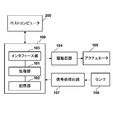
- FIG. 3 is a block diagram of the control device 100.
- the control device 100 controls the entire transport system 1 in accordance with instructions from the host computer 200.
- the control device 100 includes a processing unit 101, a storage unit 102, and an interface unit 103, which are connected to each other via a bus (not shown).
- the processing unit 101 executes a program stored in the storage unit 102.
- the processing unit 101 is a CPU, for example.
- the storage unit 102 is, for example, a RAM, a ROM, a hard disk, or the like.
- the interface unit 103 includes a communication interface that controls communication between the processing unit 101 and the host computer 200, an I / O interface that controls input / output of data between the processing unit 101 and an external device, and the like.
- the processing unit 101 outputs a control command for the actuator 105 to the drive circuit 104 to drive the actuator 105.
- the actuator 105 includes drive units 22 and 32.
- the processing unit 101 acquires the detection result of the sensor 106 via the signal processing circuit 107 and performs predetermined processing such as control of the actuator 105.
- the sensor 106 includes a sensor 50.
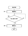
- FIGS. 4 is a flowchart of an example of conveyance control executed by the processing unit 101
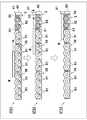
- FIGS. 5 and 6 are explanatory diagrams of the example of conveyance control, but the illustration of the conveyance unit 3C is omitted.
- control for stopping the workpiece W at the stop position SP while decelerating will be described.
- the driving of the drive units 22 and 32 is started in S1.
- power supply to the drive units 22 and 32 is started.
- the driving roller R is rotated by driving of the driving units 22 and 32.
- the rotational speed of the drive roller R is always driven at a constant speed in units of the transport units 2 and 3.
- a solid line L1 in FIG. 5 indicates the conveyance speed (the rotation speed of the drive roller R (drive shaft 5)) for each of the conveyance units 2 and 3.
- all the driving rollers R1 are rotated at the speed V1.
- all the driving rollers R1 are rotated at a speed V2 that is lower than the speed V1 (V1> V2).
- all the driving rollers R1 and R2 are rotated at a speed V3 that is lower than the speed V2 (V2> V3).
- Rotating the driving roller R causes the workpiece W located on the upstream side to be conveyed downstream.
- the workpiece W passes through the transport unit while decelerating in the order of the transport unit 3C ⁇ the transport unit 3B ⁇ the transport unit 3A ⁇ the transport unit 2.
- a state of being transported by a single transport unit (single transport state) and a state of being transported jointly by two transport units (joint transport state) can occur.
- State ST1 in FIG. 6 illustrates a joint transport state in which the workpiece W moves from the transport unit 3B to the transport unit 3A.
- the rotation speed of the drive roller R1 differs between the transport unit 3A and the transport unit 3B.
- the drive rollers R1 of both transport units 3A and 3B can all idle, even if the rotational speeds of the drive rollers R1 of both transport units 3A and 3B are different, the speed difference is caused by the drive roller R1 idling. Absorbed.
- the conveyance unit 3A having the lower conveyance speed becomes a resistance as compared with the conveyance unit 3B having the higher conveyance speed.
- the driving roller R1 on the transport unit 3B side rotates idly, the workpiece W and the driving roller R1 do not contact each other beyond a predetermined frictional force.
- the workpiece W is fed at an overspeed (speed faster than the rotation speed V2) from the conveyance unit 3B side having the higher conveyance speed as viewed from the conveyance unit 3A having the lower conveyance speed.
- the driving roller R1 is idled so that the workpiece W transported at an overspeed is allowed to pass.
- the state ST2 illustrates a single conveyance state in which the workpiece W is conveyed only by the conveyance unit 3A.
- the state ST3 illustrates a joint transport state in which the workpiece W moves from the transport unit 3A to the transport unit 2.
- the rotation speed of the drive roller R is different between the transport unit 2 and the transport unit 3A (the rotation speed V2 of the drive roller R1 in the transport unit 3A> the rotation speed V3 of the drive rollers R1 and R2 in the transport unit 2).
- the workpiece W is completely transferred to the transport unit 3A because the moment of inertia of the workpiece W is large.
- the actual conveyance speed of the workpiece W is only slightly reduced. That is, the actual conveyance speed of the workpiece W is faster than the rotation speed V2.
- the conveyance state of the workpiece W at a speed higher than the rotation speed V2 does not change much even if the conveyance of the workpiece W reaches the driving roller R1 in the conveyance unit 2.
- the drive roller R2 in the conveyance unit 2 is a direct drive type roller that does not idle, and the rotational speed V3 of the drive roller R2 and the transport speed of the workpiece W are the same. That is, since the driving roller R2 cannot tolerate a deviation between the rotation speed V3 and the conveyance speed of the workpiece W, the workpiece W is decelerated all at once. Actually, during this deceleration, slip occurs between the drive roller R2 and the workpiece W.
- the slip amount of the driving roller R1 in the transport unit 3A is further increased and the slip amount of the drive roller R1 in the transport unit 2 is decreased. Therefore, the transport speed of the workpiece W and the driving rollers R1 and R2 in the transport unit 2 are reduced. There is almost no deviation from the rotational speed V3. This deceleration effect (the effect of reducing the divergence) becomes greater as the workpiece W is transferred to the next drive roller R2.
- the case where the slip amount of the drive roller R1 in the transport unit 3A is further increased is taken as an example, but the slip amount may not change (or hardly change) depending on the speed difference between the drive rollers R1. .
- the conveyance speed of the workpiece W is the same as the rotation speed V3. Thereafter, the workpiece W is conveyed toward the stop position SP at a rotational speed V3.
- the detection result of the sensor 50 is acquired, and it is determined whether or not the workpiece W has reached the stop position SP. If the work W has reached the stop position SP, the process proceeds to S3, and if not, the process of S2 is repeated.
- a state ST4 in FIG. 6 shows a state in which the workpiece W has reached the stop position SP and has stopped moving by contacting the stop device 40.
- the drive roller R on the downstream side is a drive roller R2 that cannot idle. If there is no slip between the drive roller R2 and the work W, the work W is also stopped by stopping the rotation of the drive roller R2. Compared with the idling drive roller R1, the drive roller R2 can prevent the workpiece W from overrun. Thus, by using the driving roller R2 as the driving roller R on which the workpiece W is placed at the stop position SP, the workpiece W can be stopped more reliably at a shorter distance.
- the stopping device 40 is unnecessary.
- the rotor of the drive unit 22 may rotate by inertia even after the power supply is stopped, and the drive roller R2 may be slightly rotated. Therefore, in the present embodiment, the stop device 40 is provided to stop the workpiece W more reliably.
- the workpiece W is pressed against and brought into contact with the stop device 40 by the rotation until the rotor of the drive unit 22 rotates by inertia and the drive roller R2 completely stops driving. Therefore, when the driving roller R2 is completely stopped, the work W is also completely stopped at the contact position with respect to the stopping device 40, that is, is stopped at the stop position SP. This improves the positioning accuracy of the stop position SP of the workpiece W.
- the workpiece W stopped at the stop position SP is carried out by a robot (not shown).
- State ST12 indicates a state in which the arrival of the workpiece W at the stop position SP is detected by the sensor 50 and all the driving rollers R1 are stopped. Although the workpiece W comes into contact with the stopping device 40, the reaction of the collision at that time may cause a backward movement as shown in the state ST13. At this time, since the drive roller R1 can idle, the drive roller R1 may reversely follow the backward movement of the workpiece W. As in this embodiment, such a situation can be avoided by using the drive roller R2 that cannot be idled. As a result, the transport system 1 according to the present embodiment does not require an anti-back device (system) for preventing the workpiece W from retreating due to the collision reaction, and the device configuration is simple and inexpensive.
- system anti-back device
- the workpiece W is more reliably stopped at a shorter distance while preventing the workpiece W from being damaged. be able to.
- such an effect can be realized only by using the drive roller R1 and the drive roller R2 together, and the control of the drive units 22 and 32 is substantially ON / OFF control. Therefore, the above effect can be realized with a relatively simple configuration.
- FIG. 8 is a schematic diagram showing an example.
- the stop device 40 of this embodiment includes a movable part 41 and an actuator (not shown) that moves the movable part 41 up and down.
- the movable portion 41 moves between an ascending position on the transport track indicated by a two-dot chain line and a descending position below the transport track indicated by a solid line.
- a sensor 51 is provided.
- the sensor 51 is a sensor for a preparation position that detects that the workpiece W has reached the stop preparation position on the upstream side in the transport direction D with respect to the stop position SP.
- the sensor 51 is disposed at a different position from the sensor 50, a similar sensor can be used.
- FIG. 9 is a flowchart of an example of conveyance control executed by the processing unit 101
- FIG. 10 is an explanatory diagram of an example of conveyance control, but the illustration of the conveyance unit 3C is omitted.
- a state ST21 in FIG. 10 illustrates a joint transport state in which the workpiece W moves from the transport unit 3B to the transport unit 3A.
- the transport unit 3A and the transport unit 3B have different rotational speeds of the driving roller R1, but absorb the speed difference.
- the stopping device 40 is in a non-driven state in which the movable portion 41 is located at the lowered position.
- a state ST22 in FIG. 10 shows a state in which the workpiece W has reached the stop preparation position, which is detected by the sensor 51, and the movable portion 41 has moved up to the raised position.
- a state ST23 in FIG. 10 shows a state in which the workpiece W has reached the stop position SP, is brought into contact with the movable portion 41 of the stop device 40, and the conveyance is stopped.
- the effect exerted by the drive roller R2 when the work W is stopped is the same as that of the first embodiment, so that the work W can be stopped more reliably at a shorter distance, and the backward movement of the work W can also be avoided.
- the transport unit 2 has two drive rollers R1 and two drive rollers R2.
- the present invention is not limited to this.
- the total number of drive rollers R of the transport unit 2 is four, but the present invention is not limited to this.
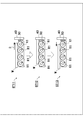
- FIG. 11 shows a plurality of other examples of the transport unit 2.
- the transport unit 2A has one drive roller R2.
- the transport unit 2B has three driving rollers R2.
- the total number of driving rollers R is 3, and one of them is the driving roller R2.
- the transport unit 2D is configured such that the total number of drive rollers R is 3, and two of them are drive rollers R2.
- the transport unit 2E has a total number of drive rollers R of 2, and one of them is a drive roller R2.
- the number of drive rollers R1 and R2 and the total number thereof can be appropriately selected depending on the deceleration, weight, etc. of the workpiece W, but there is at least one drive roller R1 on the upstream side, and the downstream side. It is sufficient to have at least one drive roller R2.
- the number of drive rollers R1 of the transport unit 3 is the same, and can be appropriately selected depending on the deceleration, weight, etc. of the workpiece W.
- the conveyance units 2 and 3 preferably include at least three drive rollers R in the conveyance direction D of the workpiece W in total.
- the drive roller R is assumed to have a relatively narrow width, and the roller conveyors 20 and 30 are provided in two rows.
- a roller conveyor having a relatively wide width (long in the rotation axis direction) may be adopted, and the roller conveyor may be configured in one row.
- FIG. 12 is a plan view showing another example of the transport unit 2.
- the transport unit 2F in the figure illustrates an example in which long drive rollers R1 'and R2' are used instead of the drive rollers R1 and R2.
- the roller conveyors are arranged in a row. As described above, different types of drive rollers R can be used as appropriate.
- the transport unit 2 is always fixedly installed.
- the transport unit 2 may be mounted on a turntable having an elevating function, and may be configured to elevate and lower. Thereby, after the work W is stopped, the work W can be transported in another direction by the transport unit 2.
- the processing unit 101 executes the control program as the control device 100.
- control is not limited to this, and control is performed by a plurality of circuits that share the processes shown in FIGS.
- the apparatus 100 may be configured.
- the transport system 1 is configured by the plurality of transport units 2 and 3.
- the transport unit 1 is not necessarily configured as a unit.
Landscapes
- Engineering & Computer Science (AREA)
- Mechanical Engineering (AREA)
- Rollers For Roller Conveyors For Transfer (AREA)
- Control Of Conveyors (AREA)
- Attitude Control For Articles On Conveyors (AREA)
Description
<搬送システム>
図1は本発明の一実施形態に係る搬送システム1の平面図であり、特に、ワークWを矢印Dで示す搬送方向に搬送しつつ、減速しながら停止位置SPで停止させる部分(減速停止装置)を図示している。ワークWは、例えば、基板等の部品や、部品とこの部品を搭載したパレット等である。
搬送ユニット2は、一対のローラコンベア20、20と、駆動部22(ここではモータ)と、伝達軸23と、を備える。ローラコンベア20、20は搬送方向Dと直交する方向に互いに離間して配置されている。
駆動ローラR1と駆動ローラR2との違いについて説明する。駆動ローラR1は駆動軸に対して空転可能なローラであり、駆動ローラR2は駆動軸に対して空転不能なローラである。搬送ユニット3は上記の通り、駆動ローラR1のみから構成されており、いわゆるアキュムレーションコンベアを構成している。図2は駆動ローラR1、R2の構成例を示す断面図である。本実施形態の場合、駆動力の伝達方式としてチェーン伝動機構を採用した場合を想定するが、歯車機構やベルト伝動機構等、他の伝動機構も採用可能である。まず、駆動ローラR1の構成例について説明する。
次に、搬送システム1の制御装置について説明する。図3は制御装置100のブロック図である。制御装置100は上位のホストコンピュータ200からの指示にしたがって、搬送システム1全体の制御を行う。
次に、処理部101によるワークWの搬送制御例について図4~図6を参照して説明する。図4は処理部101が実行する搬送制御例のフローチャート、図5及び図6は搬送制御例の説明図であるが、搬送ユニット3Cは図示を省略している。ここでは、ワークWを減速しながら停止位置SPに停止する制御を説明する。
上記第1実施形態では、停止装置40として、常時、ワークWの搬送軌道上に存在するものを想定したが、該搬送軌道に進退可能な可動式の停止装置を用いてもよい。図8はその一例を示す模式図である。本実施形態の停止装置40は可動部41と、可動部41を上下に移動するアクチュエータ(不図示)と、を備える。可動部41は、二点鎖線で示す、搬送軌道上の上昇位置と、実線で示す搬送軌道よりも下方の降下位置との間で移動する。可動部41を降下位置に位置させることで、ワークWを搬送ユニット2よりも更に下流側に搬送する搬送形態を選択できることになる。
上記第1及び第2実施形態では、搬送ユニット2の駆動ローラR1を2つ、駆動ローラR2を2つとしたが、これに限られない。また、上記第1及び第2実施形態では、搬送ユニット2の駆動ローラRの合計数を4としたが、これに限られない。図11は、搬送ユニット2の別例を複数示している。
上記第1乃至第3実施形態では、駆動ローラRとして、比較的幅が狭いものを想定し、ローラコンベア20、30を2列設けた構成とした。しかし、駆動ローラRとして比較的幅が広い(回転軸方向長さが長い)ものを採用して、ローラコンベアを1列の構成としてもよい。
上記各実施形態では、搬送ユニット2が常時固定設置される場合を想定したが、昇降機能を備えたターンテーブル上に搭載して、昇降・旋回するように構成してもよい。これにより、ワークWを停止後、搬送ユニット2によって、別の方向にワークWを搬送することも可能となる。
Claims (10)
- ワークの搬送方向に配列された複数の駆動ローラを備え、
前記複数の駆動ローラによって搬送されるワークが所定の停止位置に到達したときに、ワークの移動を停止させる搬送ユニットであって、
前記複数の駆動ローラは、
少なくとも1つの第1駆動ローラと、
前記第1駆動ローラよりも搬送方向で前記所定の停止位置側に配置された少なくとも1つの第2駆動ローラと、を含み、
前記第1駆動ローラは、駆動軸に対して空転可能なローラであり、
前記第2駆動ローラは、駆動軸に対して空転不能なローラである、
ことを特徴とする搬送ユニット。 - 請求項1に記載の搬送ユニットを複数備えた減速停止装置であって、
前記複数の搬送ユニットは互いに平行に配列され、
前記所定の停止位置においてワークと当接してワークの移動を停止させる停止装置を更に備えた、
ことを特徴とする減速停止装置。 - 各々の前記搬送ユニットは、前記第1及び第2駆動ローラをワークの搬送方向に、合わせて少なくとも3個備えた、
ことを特徴とする請求項2に記載の減速停止装置。 - ワークが前記停止位置に到達したことを検出するセンサを備えた、
ことを特徴とする請求項2に記載の減速停止装置。 - 1又は複数の第1搬送ユニットと、
前記第1搬送ユニットに対して、ワークの搬送方向で下流側に連続して配置された第2搬送ユニットと、を備えた搬送システムであって、
前記第1搬送ユニットは、
複数の駆動ローラを備えたアキュムレーションコンベアであり、
前記第2搬送ユニットは、
少なくとも1つの第1駆動ローラと、
前記第1駆動ローラよりも前記搬送方向で下流側に配置された少なくとも1つの第2駆動ローラと、を含み、
前記第1駆動ローラは、駆動軸に対して空転可能なローラであり、
前記第2駆動ローラは、駆動軸に対して空転不能なローラである、
ことを特徴とする搬送システム。 - 前記第2搬送ユニットの、前記搬送方向で下流端の停止位置において、ワークと当接してワークの移動を停止させる停止装置を更に備えた、
ことを特徴とする請求項5に記載の搬送システム。 - ワークが前記停止位置に到達したことを検出するセンサと、
前記第2搬送ユニット及び前記停止装置を制御する制御装置と、を更に備え、
前記制御装置は、
前記第2搬送ユニットを駆動制御し、かつ、前記第2搬送ユニットの前記第1駆動ローラ及び前記第2駆動ローラを、前記第1搬送ユニットの前記複数の駆動ローラよりも低速で駆動させる駆動制御部と、
前記センサにより、ワークが前記停止位置に到達したことが検出されたときに、前記第2搬送ユニットの前記第1駆動ローラ及び前記第2駆動ローラの駆動を停止する駆動停止制御部と、
を備えたことを特徴とする請求項6に記載の搬送システム。 - ワークが前記停止位置に到達したことを検出する停止位置用センサと、
ワークが前記停止位置よりも前記搬送方向で上流側の停止準備位置に到達したことを検出する準備位置用センサと、
前記第2搬送ユニット及び前記停止装置を制御する制御装置と、を更に備え、
前記制御装置は、
前記第2搬送ユニットを駆動制御し、かつ、前記第2搬送ユニットの前記第1駆動ローラ及び前記第2駆動ローラを、前記第1搬送ユニットの前記複数の駆動ローラよりも低速で駆動させる駆動制御部と、
前記準備位置用センサにより、ワークが前記停止準備位置に到達したことが検出されたときに、前記停止装置を駆動させる停止装置駆動部と、
前記停止位置用センサにより、ワークが前記停止位置に到達したことが検出されたときに、前記第2搬送ユニットの前記第1駆動ローラ及び前記第2駆動ローラの駆動を停止する駆動停止制御部とを備えた、
ことを特徴とする請求項6に記載の搬送システム。 - 請求項6に記載の搬送システムの制御方法であって、
前記第1搬送ユニットを等速度で常時駆動して、ワークを前記第1搬送ユニットにて搬送する第1搬送工程と、
前記第2搬送ユニットを前記第1搬送ユニットよりも低速な等速度で常時駆動し、前記第1搬送ユニットから前記第2搬送ユニットへワークを搬送する共同搬送工程と、
前記共同搬送工程に引き続いて前記第2搬送ユニットを前記低速な等速度で常時駆動し、前記第2搬送ユニットに搬送されたワークを前記第2搬送ユニットにて搬送する第2搬送工程と、
センサが、ワークが前記停止位置に到達したことを検出したときに、等速度で駆動中の前記第2搬送ユニットの前記第1駆動ローラ及び前記第2駆動ローラを停止させる駆動停止制御工程と、
前記駆動停止制御工程によって前記第2搬送ユニットの前記第1駆動ローラ及び前記第2駆動ローラが完全に停止するまでのそれらの回転によってワークを搬送させてワークを前記停止装置に当接させ、該ワークに衝突の反動による後退動を生じさせることなく、ワークを該当接位置で完全に停止させる停止工程と、を含む、
ことを特徴とする制御方法。 - 請求項6に記載の搬送システムの制御方法であって、
前記第1搬送ユニットを等速度で常時駆動して、ワークを前記第1搬送ユニットにて搬送する第1搬送工程と、
前記第2搬送ユニットを前記第1搬送ユニット及び前記第1搬送ユニットよりも低速な等速度で常時駆動し、前記第1搬送ユニットから前記第2搬送ユニットへワークを搬送する共同搬送工程と、
前記共同搬送工程に引き続いて前記第2搬送ユニットを前記低速な等速度で常時駆動し、前記第2搬送ユニットに搬送されたワークを前記第2搬送ユニットにて搬送する第2搬送工程と、
準備位置用センサが、ワークが前記停止位置よりも前記搬送方向で上流側の停止準備位置に到達したことを検出したときに、前記停止装置を駆動させる停止装置駆動工程と、
停止位置用センサが、ワークが前記停止位置に到達したことを検出したときに、等速度で駆動中の前記第2搬送ユニットの前記第1駆動ローラ及び前記第2駆動ローラを停止させる駆動停止制御工程と、
前記駆動停止制御工程によって前記第2搬送ユニットの前記第1駆動ローラ及び前記第2駆動ローラが完全に駆動停止するまでのそれらの回転によってワークを搬送させてワークを前記停止装置に当接させ、該ワークに衝突の反動による後退動を生じさせることなく、ワークを該当接位置で完全に停止させる停止工程と、を含む、
ことを特徴とする制御方法。
Priority Applications (5)
| Application Number | Priority Date | Filing Date | Title |
|---|---|---|---|
| KR1020157007012A KR101707929B1 (ko) | 2012-10-04 | 2012-10-04 | 반송 시스템 및 제어 방법 |
| CN201280076213.1A CN104684823B (zh) | 2012-10-04 | 2012-10-04 | 输送单元、减速停止装置、输送系统及控制方法 |
| JP2014539475A JP5941155B2 (ja) | 2012-10-04 | 2012-10-04 | 搬送システム及び制御方法 |
| PCT/JP2012/006386 WO2014054073A1 (ja) | 2012-10-04 | 2012-10-04 | 搬送ユニット、減速停止装置、搬送システム及び制御方法 |
| US14/672,918 US9469479B2 (en) | 2012-10-04 | 2015-03-30 | Transport unit, deceleration stop device, transport system, and control method |
Applications Claiming Priority (1)
| Application Number | Priority Date | Filing Date | Title |
|---|---|---|---|
| PCT/JP2012/006386 WO2014054073A1 (ja) | 2012-10-04 | 2012-10-04 | 搬送ユニット、減速停止装置、搬送システム及び制御方法 |
Related Child Applications (1)
| Application Number | Title | Priority Date | Filing Date |
|---|---|---|---|
| US14/672,918 Continuation US9469479B2 (en) | 2012-10-04 | 2015-03-30 | Transport unit, deceleration stop device, transport system, and control method |
Publications (1)
| Publication Number | Publication Date |
|---|---|
| WO2014054073A1 true WO2014054073A1 (ja) | 2014-04-10 |
Family
ID=50434441
Family Applications (1)
| Application Number | Title | Priority Date | Filing Date |
|---|---|---|---|
| PCT/JP2012/006386 Ceased WO2014054073A1 (ja) | 2012-10-04 | 2012-10-04 | 搬送ユニット、減速停止装置、搬送システム及び制御方法 |
Country Status (5)
| Country | Link |
|---|---|
| US (1) | US9469479B2 (ja) |
| JP (1) | JP5941155B2 (ja) |
| KR (1) | KR101707929B1 (ja) |
| CN (1) | CN104684823B (ja) |
| WO (1) | WO2014054073A1 (ja) |
Cited By (4)
| Publication number | Priority date | Publication date | Assignee | Title |
|---|---|---|---|---|
| JP2017100829A (ja) * | 2015-11-30 | 2017-06-08 | 株式会社日本設計工業 | ローラユニット及びローラコンベア |
| CN108436378A (zh) * | 2018-06-04 | 2018-08-24 | 常源科技(天津)有限公司 | 一种用于焊接系统的焊接生产线 |
| CN115959409A (zh) * | 2023-03-16 | 2023-04-14 | 安徽金豪包装科技有限公司 | 一种包装盒加工用滚筒输送机 |
| WO2025146734A1 (ja) * | 2024-01-05 | 2025-07-10 | 村田機械株式会社 | 自動倉庫 |
Families Citing this family (20)
| Publication number | Priority date | Publication date | Assignee | Title |
|---|---|---|---|---|
| CA3105934C (en) * | 2016-01-11 | 2022-08-02 | Opex Corporation | Material handling apparatus with delivery vehicles |
| NL2016340B1 (en) * | 2016-03-01 | 2017-09-11 | Rexnord Flattop Europe Bv | Method and system for transporting products. |
| CN106241158B (zh) * | 2016-08-31 | 2018-10-19 | 中国大冢制药有限公司 | 组合式仓储货物出入库输送设备控制系统 |
| CN106395282B (zh) * | 2016-11-17 | 2019-12-13 | 吴江南 | 一种用于袋装货物叠装生产线上的对开门装置 |
| JP6729466B2 (ja) * | 2017-03-28 | 2020-07-22 | 株式会社ダイフク | 物品搬送設備 |
| US10889449B2 (en) | 2017-09-25 | 2021-01-12 | Canon Kabushiki Kaisha | Transport system and manufacturing method of article |
| JP6659744B2 (ja) * | 2018-01-25 | 2020-03-04 | ファナック株式会社 | ロボットシステム |
| CN111902784B (zh) * | 2018-05-31 | 2023-04-07 | 村田机械株式会社 | 搬送系统 |
| CN109911553A (zh) * | 2018-12-24 | 2019-06-21 | 珠海格力智能装备有限公司 | 输送设备及输送方法 |
| DE102019217682A1 (de) * | 2019-02-21 | 2020-08-27 | Sms Group Gmbh | Vorrichtung und Verfahren zum Transportieren von Bandmaterial, insbesondere Warmband |
| CN111252451A (zh) * | 2019-09-20 | 2020-06-09 | 库卡柔性系统(上海)有限公司 | 一种积放辊道用机械阻尼器及其积放辊道 |
| US10858198B1 (en) | 2019-10-02 | 2020-12-08 | Intelligrated Headquarters, Llc | Singulation conveyor system with rollers of different roller cross-sectional profiles |
| CN114641441B (zh) * | 2019-11-01 | 2024-04-09 | 平田机工株式会社 | 移动台、基座单元以及移动单元 |
| CN111302203B (zh) * | 2020-03-09 | 2024-09-10 | 中冶赛迪技术研究中心有限公司 | 一种小型棒材的防脱吊装台架及系统 |
| CN113198780A (zh) * | 2021-04-30 | 2021-08-03 | 重庆市渝大节能玻璃有限公司 | 玻璃清洗线 |
| CN113086492B (zh) * | 2021-05-14 | 2022-03-29 | 攀钢集团西昌钢钒有限公司 | 一种铸坯辊道输送控制系统及控制方法 |
| CN113682719B (zh) * | 2021-08-13 | 2023-08-11 | 宣城吉鼎玻机械有限公司 | 一种玻璃钢化炉的玻璃上片方法 |
| CN113911433A (zh) * | 2021-11-18 | 2022-01-11 | 九江市启田智能科技有限公司 | 一种羽绒服包装设备 |
| CN115123774B (zh) * | 2022-06-09 | 2023-08-15 | 北京金隅天坛家具股份有限公司 | 一种家居物流rgv定位方法 |
| CN115231279A (zh) * | 2022-06-16 | 2022-10-25 | 苏州镁伽科技有限公司 | 阻挡限位装置和方法、上料装置、存储介质和电子设备 |
Citations (7)
| Publication number | Priority date | Publication date | Assignee | Title |
|---|---|---|---|---|
| JPH09290918A (ja) * | 1996-04-30 | 1997-11-11 | Kubota Corp | 育苗箱移し換え装置 |
| JPH11165834A (ja) * | 1997-12-08 | 1999-06-22 | Yuyama Seisakusho:Kk | 薬剤のコンベア装置 |
| JPH11199030A (ja) * | 1998-01-07 | 1999-07-27 | Daifuku Co Ltd | コンベヤ装置 |
| JP2002176091A (ja) * | 2000-12-08 | 2002-06-21 | Fuji Photo Film Co Ltd | 基板搬送装置及び方法 |
| JP2003086654A (ja) * | 2001-09-14 | 2003-03-20 | Dainippon Screen Mfg Co Ltd | 基板処理装置 |
| JP2004075311A (ja) * | 2002-08-20 | 2004-03-11 | Ito Denki Kk | 搬送装置 |
| JP2005119798A (ja) * | 2003-10-16 | 2005-05-12 | Daifuku Co Ltd | 搬送装置 |
Family Cites Families (20)
| Publication number | Priority date | Publication date | Assignee | Title |
|---|---|---|---|---|
| US4325474A (en) * | 1978-06-05 | 1982-04-20 | Rexnord Inc. | Slip friction roller drive |
| US4266660A (en) * | 1979-08-02 | 1981-05-12 | Smock Material Handling Company, Inc. | Accumulating-type powered roller conveyor |
| US4798282A (en) * | 1987-11-17 | 1989-01-17 | Hitech Robotics Ltd. | Zoning conveyor |
| DE4007707A1 (de) * | 1989-03-11 | 1990-09-20 | Duerr Gmbh & Co | Rollenbahn fuer skids |
| US5174434A (en) * | 1992-05-22 | 1992-12-29 | Davidson Textron Inc. | Apparatus for providing rotational motion on a carrier moving along a driven conveyor |
| US5318167A (en) * | 1993-03-12 | 1994-06-07 | Newcor, Inc. | Control system for power driven conveyor line |
| US5558205A (en) * | 1994-09-26 | 1996-09-24 | Quickdraw Design And Drafting, Inc. | Conveyors |
| US5558206A (en) * | 1994-09-26 | 1996-09-24 | Quickdraw Design And Drafting, Inc. | Conveyor technology |
| JPH09188414A (ja) | 1996-01-10 | 1997-07-22 | Canon Inc | コンベア及び該コンベアを用いたワークの搬送方法 |
| US6193047B1 (en) * | 1996-09-25 | 2001-02-27 | Shuttleworth, Inc. | Ergonomic workstation conveyor apparatus and method |
| JP2000085955A (ja) | 1998-09-09 | 2000-03-28 | Fuji Photo Film Co Ltd | シート材の搬送方法 |
| JP3421689B2 (ja) * | 2000-04-06 | 2003-06-30 | 伊東電機株式会社 | ローラコンベアのゾーン制御方法並びにゾーンコントローラ |
| US20060260911A1 (en) * | 2003-03-18 | 2006-11-23 | Shuttleworth, Inc. | Rapid reconfigurable servo correction cone conveyor |
| JP3799404B2 (ja) * | 2003-08-25 | 2006-07-19 | 伊東電機株式会社 | ゾーン制御式コンベアシステムおよびゾーンコントローラ |
| US7503450B2 (en) * | 2007-08-13 | 2009-03-17 | Magstar Technologies, Inc. | Long roller slip conveyor |
| US7748520B1 (en) * | 2008-09-23 | 2010-07-06 | Activar Technical Products Group, Inc. | Slip roller conveyor |
| JP5439137B2 (ja) * | 2009-11-27 | 2014-03-12 | 豊明工業株式会社 | コンベヤ装置 |
| CN201882533U (zh) * | 2010-11-29 | 2011-06-29 | 昆明钦瑜机械有限公司 | 手自切换的密闭式烟叶收购装置 |
| ES2641716T3 (es) * | 2011-02-18 | 2017-11-13 | Laitram, Llc | Transportador de rodillos de diámetro pequeño |
| CN202321449U (zh) * | 2011-11-15 | 2012-07-11 | 嘉兴市新纪元钢管制造有限公司 | 一种二级链动调速装置 |
-
2012
- 2012-10-04 KR KR1020157007012A patent/KR101707929B1/ko not_active Expired - Fee Related
- 2012-10-04 WO PCT/JP2012/006386 patent/WO2014054073A1/ja not_active Ceased
- 2012-10-04 JP JP2014539475A patent/JP5941155B2/ja not_active Expired - Fee Related
- 2012-10-04 CN CN201280076213.1A patent/CN104684823B/zh not_active Expired - Fee Related
-
2015
- 2015-03-30 US US14/672,918 patent/US9469479B2/en not_active Expired - Fee Related
Patent Citations (7)
| Publication number | Priority date | Publication date | Assignee | Title |
|---|---|---|---|---|
| JPH09290918A (ja) * | 1996-04-30 | 1997-11-11 | Kubota Corp | 育苗箱移し換え装置 |
| JPH11165834A (ja) * | 1997-12-08 | 1999-06-22 | Yuyama Seisakusho:Kk | 薬剤のコンベア装置 |
| JPH11199030A (ja) * | 1998-01-07 | 1999-07-27 | Daifuku Co Ltd | コンベヤ装置 |
| JP2002176091A (ja) * | 2000-12-08 | 2002-06-21 | Fuji Photo Film Co Ltd | 基板搬送装置及び方法 |
| JP2003086654A (ja) * | 2001-09-14 | 2003-03-20 | Dainippon Screen Mfg Co Ltd | 基板処理装置 |
| JP2004075311A (ja) * | 2002-08-20 | 2004-03-11 | Ito Denki Kk | 搬送装置 |
| JP2005119798A (ja) * | 2003-10-16 | 2005-05-12 | Daifuku Co Ltd | 搬送装置 |
Cited By (4)
| Publication number | Priority date | Publication date | Assignee | Title |
|---|---|---|---|---|
| JP2017100829A (ja) * | 2015-11-30 | 2017-06-08 | 株式会社日本設計工業 | ローラユニット及びローラコンベア |
| CN108436378A (zh) * | 2018-06-04 | 2018-08-24 | 常源科技(天津)有限公司 | 一种用于焊接系统的焊接生产线 |
| CN115959409A (zh) * | 2023-03-16 | 2023-04-14 | 安徽金豪包装科技有限公司 | 一种包装盒加工用滚筒输送机 |
| WO2025146734A1 (ja) * | 2024-01-05 | 2025-07-10 | 村田機械株式会社 | 自動倉庫 |
Also Published As
| Publication number | Publication date |
|---|---|
| JP5941155B2 (ja) | 2016-06-29 |
| JPWO2014054073A1 (ja) | 2016-08-25 |
| CN104684823B (zh) | 2016-09-28 |
| CN104684823A (zh) | 2015-06-03 |
| US9469479B2 (en) | 2016-10-18 |
| US20150203298A1 (en) | 2015-07-23 |
| KR20150046205A (ko) | 2015-04-29 |
| KR101707929B1 (ko) | 2017-02-17 |
Similar Documents
| Publication | Publication Date | Title |
|---|---|---|
| JP5941155B2 (ja) | 搬送システム及び制御方法 | |
| KR950014457B1 (ko) | 롤러컨베이어 | |
| KR101360857B1 (ko) | 컨베이어 장치, 컨베이어 제조 방법, 물체 이송 방법,컨베이어 벨트, 및 물체 배치 방법 | |
| US20130213768A1 (en) | Accumulation conveyor | |
| TWI653702B (zh) | 用於潔淨環境之大體積輸送機運輸系統 | |
| EP2297006A1 (en) | Conveyor with a gentle retractable stop | |
| CN112320244B (zh) | 一种输送装置 | |
| JPH06171801A (ja) | 搬送路内で紙シートを回転せしめる装置 | |
| KR100317557B1 (ko) | 이송대차 | |
| KR100534031B1 (ko) | 리테이너의 위치어긋남 방지장치 | |
| JP2581680Y2 (ja) | 板材搬送装置 | |
| JPH09188414A (ja) | コンベア及び該コンベアを用いたワークの搬送方法 | |
| JP5559676B2 (ja) | ワーク停止装置及びそれを用いたワーク停止方法 | |
| JP2010235276A (ja) | 搬送装置 | |
| JP5154117B2 (ja) | ベルトコンベヤ装置および搬送装置 | |
| JP2007055721A (ja) | ワーク搬送装置 | |
| JP2007269431A (ja) | 台車移動装置 | |
| JP2013033785A (ja) | 基板搬送装置 | |
| KR102521513B1 (ko) | 깨끗한 환경들을 위한 대량의 컨베이어 이송 장치 | |
| CN117342250A (zh) | 一种长传输花篮挡停装置及输送系统 | |
| JP2001192117A (ja) | 搬送方向変換装置 | |
| JP2001163410A (ja) | 物品の切出し搬送装置の緊急停止方法 | |
| KR20150039266A (ko) | 이중 구조의 풀리를 이용한 자동운반 장치 및 그 방법 | |
| JPH07300223A (ja) | 板材などの転換移送装置 | |
| JP2007145456A (ja) | コンベア設備 |
Legal Events
| Date | Code | Title | Description |
|---|---|---|---|
| 121 | Ep: the epo has been informed by wipo that ep was designated in this application |
Ref document number: 12886108 Country of ref document: EP Kind code of ref document: A1 |
|
| ENP | Entry into the national phase |
Ref document number: 2014539475 Country of ref document: JP Kind code of ref document: A |
|
| ENP | Entry into the national phase |
Ref document number: 20157007012 Country of ref document: KR Kind code of ref document: A |
|
| NENP | Non-entry into the national phase |
Ref country code: DE |
|
| 122 | Ep: pct application non-entry in european phase |
Ref document number: 12886108 Country of ref document: EP Kind code of ref document: A1 |