WO2014051012A1 - 車両部品の連結構造 - Google Patents
車両部品の連結構造 Download PDFInfo
- Publication number
- WO2014051012A1 WO2014051012A1 PCT/JP2013/076160 JP2013076160W WO2014051012A1 WO 2014051012 A1 WO2014051012 A1 WO 2014051012A1 JP 2013076160 W JP2013076160 W JP 2013076160W WO 2014051012 A1 WO2014051012 A1 WO 2014051012A1
- Authority
- WO
- WIPO (PCT)
- Prior art keywords
- cowl
- vehicle
- hole
- gate
- fastening
- Prior art date
- Legal status (The legal status is an assumption and is not a legal conclusion. Google has not performed a legal analysis and makes no representation as to the accuracy of the status listed.)
- Ceased
Links
Images


Classifications
-
- B—PERFORMING OPERATIONS; TRANSPORTING
- B62—LAND VEHICLES FOR TRAVELLING OTHERWISE THAN ON RAILS
- B62J—CYCLE SADDLES OR SEATS; AUXILIARY DEVICES OR ACCESSORIES SPECIALLY ADAPTED TO CYCLES AND NOT OTHERWISE PROVIDED FOR, e.g. ARTICLE CARRIERS OR CYCLE PROTECTORS
- B62J17/00—Weather guards for riders; Fairings or stream-lining parts not otherwise provided for
-
- B—PERFORMING OPERATIONS; TRANSPORTING
- B62—LAND VEHICLES FOR TRAVELLING OTHERWISE THAN ON RAILS
- B62J—CYCLE SADDLES OR SEATS; AUXILIARY DEVICES OR ACCESSORIES SPECIALLY ADAPTED TO CYCLES AND NOT OTHERWISE PROVIDED FOR, e.g. ARTICLE CARRIERS OR CYCLE PROTECTORS
- B62J23/00—Other protectors specially adapted for cycles
-
- B—PERFORMING OPERATIONS; TRANSPORTING
- B62—LAND VEHICLES FOR TRAVELLING OTHERWISE THAN ON RAILS
- B62J—CYCLE SADDLES OR SEATS; AUXILIARY DEVICES OR ACCESSORIES SPECIALLY ADAPTED TO CYCLES AND NOT OTHERWISE PROVIDED FOR, e.g. ARTICLE CARRIERS OR CYCLE PROTECTORS
- B62J35/00—Fuel tanks specially adapted for motorcycles or engine-assisted cycles; Arrangements thereof
-
- F—MECHANICAL ENGINEERING; LIGHTING; HEATING; WEAPONS; BLASTING
- F16—ENGINEERING ELEMENTS AND UNITS; GENERAL MEASURES FOR PRODUCING AND MAINTAINING EFFECTIVE FUNCTIONING OF MACHINES OR INSTALLATIONS; THERMAL INSULATION IN GENERAL
- F16B—DEVICES FOR FASTENING OR SECURING CONSTRUCTIONAL ELEMENTS OR MACHINE PARTS TOGETHER, e.g. NAILS, BOLTS, CIRCLIPS, CLAMPS, CLIPS OR WEDGES; JOINTS OR JOINTING
- F16B21/00—Means for preventing relative axial movement of a pin, spigot, shaft or the like and a member surrounding it; Stud-and-socket releasable fastenings
- F16B21/10—Means for preventing relative axial movement of a pin, spigot, shaft or the like and a member surrounding it; Stud-and-socket releasable fastenings by separate parts
- F16B21/12—Means for preventing relative axial movement of a pin, spigot, shaft or the like and a member surrounding it; Stud-and-socket releasable fastenings by separate parts with locking-pins or split-pins thrust into holes
- F16B21/125—Means for preventing relative axial movement of a pin, spigot, shaft or the like and a member surrounding it; Stud-and-socket releasable fastenings by separate parts with locking-pins or split-pins thrust into holes radially resilient or with a snap-action member, e.g. elastic tooth, pawl with spring, resilient coil or wire
-
- F—MECHANICAL ENGINEERING; LIGHTING; HEATING; WEAPONS; BLASTING
- F16—ENGINEERING ELEMENTS AND UNITS; GENERAL MEASURES FOR PRODUCING AND MAINTAINING EFFECTIVE FUNCTIONING OF MACHINES OR INSTALLATIONS; THERMAL INSULATION IN GENERAL
- F16B—DEVICES FOR FASTENING OR SECURING CONSTRUCTIONAL ELEMENTS OR MACHINE PARTS TOGETHER, e.g. NAILS, BOLTS, CIRCLIPS, CLAMPS, CLIPS OR WEDGES; JOINTS OR JOINTING
- F16B5/00—Joining sheets or plates, e.g. panels, to one another or to strips or bars parallel to them
- F16B5/06—Joining sheets or plates, e.g. panels, to one another or to strips or bars parallel to them by means of clamps or clips
- F16B5/0607—Joining sheets or plates, e.g. panels, to one another or to strips or bars parallel to them by means of clamps or clips joining sheets or plates to each other
- F16B5/0621—Joining sheets or plates, e.g. panels, to one another or to strips or bars parallel to them by means of clamps or clips joining sheets or plates to each other in parallel relationship
- F16B5/0642—Joining sheets or plates, e.g. panels, to one another or to strips or bars parallel to them by means of clamps or clips joining sheets or plates to each other in parallel relationship the plates being arranged one on top of the other and in full close contact with each other
-
- F—MECHANICAL ENGINEERING; LIGHTING; HEATING; WEAPONS; BLASTING
- F16—ENGINEERING ELEMENTS AND UNITS; GENERAL MEASURES FOR PRODUCING AND MAINTAINING EFFECTIVE FUNCTIONING OF MACHINES OR INSTALLATIONS; THERMAL INSULATION IN GENERAL
- F16B—DEVICES FOR FASTENING OR SECURING CONSTRUCTIONAL ELEMENTS OR MACHINE PARTS TOGETHER, e.g. NAILS, BOLTS, CIRCLIPS, CLAMPS, CLIPS OR WEDGES; JOINTS OR JOINTING
- F16B5/00—Joining sheets or plates, e.g. panels, to one another or to strips or bars parallel to them
- F16B5/06—Joining sheets or plates, e.g. panels, to one another or to strips or bars parallel to them by means of clamps or clips
- F16B5/0607—Joining sheets or plates, e.g. panels, to one another or to strips or bars parallel to them by means of clamps or clips joining sheets or plates to each other
- F16B5/0621—Joining sheets or plates, e.g. panels, to one another or to strips or bars parallel to them by means of clamps or clips joining sheets or plates to each other in parallel relationship
- F16B5/0657—Joining sheets or plates, e.g. panels, to one another or to strips or bars parallel to them by means of clamps or clips joining sheets or plates to each other in parallel relationship at least one of the plates providing a raised structure, e.g. of the doghouse type, for connection with the clamps or clips of the other plate
-
- Y—GENERAL TAGGING OF NEW TECHNOLOGICAL DEVELOPMENTS; GENERAL TAGGING OF CROSS-SECTIONAL TECHNOLOGIES SPANNING OVER SEVERAL SECTIONS OF THE IPC; TECHNICAL SUBJECTS COVERED BY FORMER USPC CROSS-REFERENCE ART COLLECTIONS [XRACs] AND DIGESTS
- Y10—TECHNICAL SUBJECTS COVERED BY FORMER USPC
- Y10T—TECHNICAL SUBJECTS COVERED BY FORMER US CLASSIFICATION
- Y10T403/00—Joints and connections
- Y10T403/70—Interfitted members
- Y10T403/7075—Interfitted members including discrete retainer
Definitions
- the present invention relates to a connecting structure of parts for vehicles in which a plurality of vehicle parts such as cowl separated in front and rear are connected by clips in a saddle-ride type vehicle.
- the cowl members of the saddle-ride type vehicle individually form a plurality of cowl members different in material etc. and combine them to form one cowl member There is something to do.
- a first restraint element is provided in a protruding manner on one cowl member
- a second restraint element is provided in a protruding manner for the other cowl member
- the first and second restraint elements are connected in a buckle manner
- a structure in which the cowl is connected by being held by a separate clip (see Patent Document 1).
- the restraint element is increased in size, so the cowl member is increased in size.
- the restraint element increases the size of the vehicle body or Space layout becomes difficult. Therefore, it is required to make the cowl connection good while miniaturizing the restraint element.
- the present application fulfills such a need.
- the invention relates to a connecting structure of vehicle parts in which a first member and a second member made of resin are connected by a clip, The first and second members are respectively fastened to a vehicle,
- the first member includes a rectangular through hole having a short side and a long side
- the second member comprises a gate penetrating the through hole;
- the gate has a U-shape including a pair of feet projecting from the surface of the second member and a top connecting the projecting tips of the feet.
- the pair of foot portions are provided along the short side of the through hole, The clip is engaged with the through hole and the gate to connect the first member and the second member in a state where the gate penetrates the through hole.
- the invention according to claim 2 is characterized in that, in the above-mentioned claim 1, the first member and the second member are a first cowl and a second cowl respectively covering a part of the vehicle.
- the invention of claim 3 is characterized in that, in the above-mentioned claim 2, the first cowl and the second cowl are each fastened to a vehicle, and a plurality of at least one fastening portion is provided.
- the invention of claim 4 is characterized in that, in the above-mentioned claim 3, the fastening portion is screw fastening or insertion fastening.
- the invention of claim 5 is any one of the above-mentioned claims 2 to 4 in which
- the first cowl and the second cowl constitute a tank cowl disposed on a side surface of a saddle-ride type vehicle,
- the first cowl and the second cowl are arranged back and forth, and the connecting portion by the clip is arranged in the vertical direction of the vehicle, and the first cowl and the second cowl to the vehicle above and below the connecting portion
- the said fastening part for fastening is arrange
- the joint line formed in the joint portion of the first cowl and the second cowl in the vicinity of the connection portion has a linear portion, and this linear portion is the long side of the through hole. And the parallel arrangement.
- the invention of claim 7 is the same as in claim 5 or 6 above.
- the saddle-ride type vehicle supports an engine on a vehicle body frame below the tank cowl, A cylinder axis of the engine is disposed substantially in parallel with a long side of the through hole.
- the invention of claim 8 is the same as in claim 2 above.
- the first cowl and the second cowl are a left cowl and a right cowl divided into right and left that constitute an under cowl covering a lower part of a saddle-ride type vehicle, While fastening the upper part of these left and right cowls to the vehicle, The lower portions are connected by the clip.
- the invention of claim 9 is the same as in claim 1 above.
- the first member is a member disposed under a seat and fastened to a vehicle body frame, and includes the through hole
- the second member is a member having a safety part of a saddle-ride type vehicle and a mounting portion attached to the vehicle body frame, and the mounting portion is provided with the gate.
- the clip since the first member and the second member are respectively fastened to the vehicle, it is possible to reduce the stress applied to the connecting portion. Therefore, the clip can also be miniaturized. In addition, since it is only necessary to insert the clip into a portion protruding from the through hole of the gate, a simple connection structure is obtained, which improves the maintainability.
- the connecting structure of the first cowl and the second cowl can be simplified, and the cowl can be miniaturized.
- the rotation of the first and second cowls due to the traveling wind can be prevented, and the stress applied to the connecting portion can be further reduced to miniaturize the connecting portion and the cowl.
- fastening portion is screw fastening or insertion fastening, fastening of the first cowl and the second cowl can be made favorable.
- the coupling portion is disposed at a good position while having a cowl fastening structure that can withstand traveling wind. can do.
- the connecting portion of the first cowl and the second cowl in the vertical direction of the vehicle and fastening the upper and lower portions of this connecting portion to the vehicle, the rotation of the first cowl and the second cowl can be made more reliably. It is possible to prevent and reduce the stress on the connection.
- the longitudinal direction of the through hole in parallel with the linear portion of the mating line, it is possible to miniaturize the cowl by reducing the necessary connecting portion such as overlapping in the mating portion. Further, even when stress is applied to open the connecting portion from the outer surface of the cowl, the stress applied to the through hole can be reduced by receiving the shift of the connecting portion in the longitudinal direction of the through hole.
- the long side of the through hole is arranged in parallel to the primary vibration of the engine, so that the primary vibration of the engine is received by the foot of the gate, and the connection of wear by the clip Can be reduced, and the replacement cycle of the clip can be lengthened.
- the first member and the second member are formed as an under cowl, the lower portions thereof are joined together and connected, and the upper portion is fastened to the vehicle, so that the mass of the under cowl does not overlap the connecting portion. be able to.
- the first member is a member supported by the vehicle body frame under the seat
- the second member is a member having the safety part and the attachment portion to the vehicle body frame.
- the second member can be easily supported by the vehicle by connecting the second member with the rectangular through hole and the connection portion by the gate and connecting with the clip.
- the connecting portion between the first member and the second member can be miniaturized, and the clip can also be miniaturized.
- the second member can be separated from the first member and can be quickly removed from the vehicle body frame, it can be easily removed during race driving where safety parts are unnecessary, which is suitable for a race specification vehicle.
- the connecting portion between the first member and the second member can be covered and concealed, and the security component can be made less likely to be tampered with.
- FIG. 5 is a cross-sectional view taken along line 5-5 of FIG. 2 (A) and a cross-sectional view taken along arrow X1 of A (B)
- Cross section showing the process of inserting the gate into the through hole and attaching the clip Sectional drawing which shows the connection structure of the under cowl which concerns on another embodiment Installation explanatory drawing of the taillight assembly which concerns on another embodiment
- each direction of upper and lower, left and right, front and back is based on a vehicle to be applied in principle, and in the drawings, the upper side is indicated by UP, the left side by LH, and the front by Fr. Also, the inside of the vehicle is indicated by IN and the outside is indicated by OUT. Furthermore, the upper, lower, left, right, front and rear directions of the clip are based on the state shown in FIG.
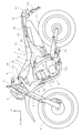
- FIG. 1 is a left side view of an off-road bike that is an example of a saddle-ride type vehicle according to the present embodiment.
- a pair of left and right front forks 3 is rotatably supported via a head pipe 2 provided at the front end of the vehicle body frame 1, and a front wheel 4 is supported at the lower end of the front fork 3.
- the front wheel 4 is steered by a steering wheel 5 connected to the upper end of the front fork 3.
- the vehicle body frame 1 includes a main frame 6 and a down frame 7, and an engine 8 is supported therebetween.
- the main frame 6 extends rearward and obliquely downward from the head pipe 2 through the upper side of the engine 8 and further extends downward of the rear of the engine 8.
- the down frame 7 extends diagonally downward and rearward from the head pipe 2 in front of the engine 8 and further extends rearward below the engine 8 and is connected to the rear end of the main frame 6.
- a fuel tank 9 is supported above the main frame 6, a seat 10 is disposed behind the fuel tank 9, and supported by a seat rail 11.
- a pair of left and right seat rails 11 is provided to the rear at a slanting upward from the main frame 6.
- the front end of the rear swing arm 12 is pivotally mounted at the rear end of the main frame 6 via a pivot 12a, and the rear wheel 13 is supported at the rear end of the rear swing arm 12.
- the side of the vehicle body frame 1 is covered by a tank cowl 14.
- the tank cowl 14 is composed of a front cowl 15 and a rear cowl 16 which are separately provided.
- the front cowl 15 and the rear cowl 16 correspond to the first member and the second member of the present invention, respectively, and are connected to each other as described later.
- the rear end of the rear cowl 16 is connected to a side cowl 17 that covers the lower side of the seat 10.
- the tank cowl 14 and the side cowl 17 are provided as a pair on the left and right, respectively.
- a luggage box 60 is disposed inside the side cowl 17 and supported by the seat rail 11. Further, a taillight assembly 61 projects rearward from below the rear end of the side cowl 17.
- the taillight assembly 61 has its front end portion supported by the seat rail 11, and is connected to the luggage box 60 so as to be detachable.
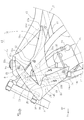
- the front cowl 15 is a vehicle body cover member that covers the upper front portion of the cylinder portion 18 that constitutes the engine 8 from the front side of the fuel tank 9, and is made of an appropriate rigid material such as synthetic resin. It is done.
- the front cowl 15 has a substantially arrow shape projecting forward in a side view, the tip 20 overlaps the side outward of the front fork 3, the upper portion 21 extends obliquely rearward and upward, and crosses the side of the main frame 6
- the upper end 21a is fastened to a stay 9a formed on the side of the fuel tank 9 by a bolt 22 so as to overlap the front side of the fuel tank 9.
- the bolt 22 corresponds to the screw fastening in the present invention.
- insertion fastening like a fastener which fastening is completed only by inserting a lock member is also possible.
- the lower portion 23 extends obliquely downward and rearward while overlapping with the side of the down frame 7, and the lower end 23 a is fastened to the lower portion of the radiator 19 with a bolt 24.
- the radiator 19 is disposed behind the down frame 7 and is supported by the main frame 6 and the down frame 7. For this reason, The lower portion 23 is supported on the vehicle body frame 1 side via the radiator 19.
- a recess 25 is formed between the rear portions of the upper portion 21 and the lower portion 23. The recess 25 is in the forward direction behind the tip 20.
- the rear cowl 16 has a front portion 30 projecting forward in an acute angle shape, an upper portion 31 extending rearward from the front portion 30 with an upper edge having a substantially mountain shape in a side view, and a lower portion 33 extending downward. .
- the front portion 30 enters the recess 25 of the front cowl 15.
- the upper portion 31 is fastened to the side surface of the main frame 6 with bolts 32 at a mountain-shaped top 31a.
- the front edge 31 b forward of the top 31 a forms an acute triangular space with the rear edge of the upper portion 21.
- the rear side edge 31 c rearward of the top 31 a overlaps the lower side of the fuel tank 9 and extends rearward, and the rear end 31 d is in contact with the front end of the side cowl 17.
- the front end of the side cowl 17 is fastened to the seat rail 11 by a bolt 17a.
- the lower end edge 31 e of the upper portion 31 is located above the cylinder 18 and exposes the cylinder 18.
- the side surface of the fuel tank 9 is a portion used for knee grip by the driver, and the rear cowl 16 is in the range where knee grip is performed, which makes the driver feel good with respect to the knee grip portion.
- the lower portion 23 of the front cowl 15 and the lower portion 33 of the rear cowl 16 are connected to form a straight alignment line 14a.
- the mating line 14a is inclined forward so that the upper side is directed forward, and is substantially parallel to the cylinder axis CL.
- the relationship with the cylinder axis line CL may form various intersecting angles as long as it is non-orthogonal to the cylinder axis line CL.
- the front cowl 15 and the rear cowl 16 are connected by a connecting portion 14b (described in detail later) along the alignment line 14a.
- a plurality of (in this example, three places) connecting portions 14 b are provided in the vertical direction.
- a straight mating line 14c is also formed between the edge of the lower part 23 of the front cowl 15 facing the recess 25 and the front part 30 of the rear cowl 16, but this mating line 14c is the cylinder axis CL. On the other hand, they meet at an inclination larger than the fitting line 14a.
- the lower portion 33 is a portion continuously extending downward from the front portion 30 in the form of an acute triangle, and the tip 33a of the lower portion 33 is in the vicinity of the bolt 24 to overlap the upper front side surface of the cylinder portion 18
- the upper portion 33b is curved and continues to the lower end edge 31e.
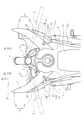
- the rear edge 23 b of the lower portion 23 is provided with a flange 26.
- the flange 26 extends vertically along the rear edge 23 b, and the upper side of the flange 26 extends into the recess 25.
- a plurality of through holes 27 constituting the connecting portion 14 b are provided in the vertical direction at a portion below the concave portion 25 of the flange 26.
- a total of three through holes 27 are provided, one in the portion of the flange 26 parallel to the mating line 14c (FIG. 2) and two in the portion parallel to the mating line 14a (FIG. 2). There is.
- the flange 26 is a step in which the edge of the lower portion 23 is stepped into the vehicle body by about the thickness of the rear cowl 16, and the upper connecting edge provided on the front 30 of the rear cowl 16 outside the flange 26.
- the lower bonding edges 37 provided at 36 and the lower part 33 overlap. After overlapping with the flange 26, the upper coupling edge 36 and the lower coupling edge 37 of the cowl 16 abut against the step upper portion 28a and the step 28 formed along the flange 26 at which the mating line 14a While forming, the outer surfaces of the front cowl 15 and the rear cowl 16 are flush.
- a gate 38 which is inserted into and penetrates the through hole 27 projects toward the inside of the vehicle body.
- the through holes 27 and the gates 38 constitute a connecting portion 14 b, and are formed in the same number as the connecting portions 14 b in the vertical direction along the alignment line 14 a.
- the step 28 corresponding to the lower coupling edge 37 has a linear shape substantially parallel to the cylinder axis CL.
- the step upper portion 28a corresponding to the upper joint edge portion 36 in the step 28 is also linear, it is largely non-parallel to the cylinder axis CL.
- Reference numerals 22a, 32a and 24a in FIG. 4 denote bolt holes and fastening seats for the bolts 22, 32 and 24, respectively.
- the left and right tank cowls 14 are spread forward to the side, so that a large amount of traveling wind WD can be efficiently taken in and can be made to flow in the direction of the radiator 19.
- the wind pressure received by the front cowl 15 is increased by taking in a large amount of the traveling wind WD, so that the left and right front cowls 15 receive a force so as to be spread, and the wind pressure against the connecting portion 14b of the rear cowl 16 The big power comes to be added.
- the connection structure of the front cowl 15 and the rear cowl 16 will be described with reference to FIGS.
- the flange 26 of the lower portion 23 is recessed inward of the vehicle by the thickness T1 of the lower connecting edge 37, and the lower connecting edge 37 is flush with the lower connecting edge 37.
- the surface on which the rear cowl 16 of the flange 26 overlaps is referred to as the mating surface 26a, and the opposite side is referred to as the inner surface 26a.
- the upper coupling edge 36 (FIG. 4) is likewise flush with the flange 26.
- a gate 38 formed in the upper coupling edge 36 and the lower coupling edge 37 penetrates, and a portion thereof protrudes inward of the vehicle body.
- a clip 40 (described in detail later).
- the connecting portion 14 b of the front cowl 15 and the rear cowl 16 through the through hole 27 and the gate 38 has the through hole 27 located inside the rear cowl 16 and the gate 38 protrudes inward of the rear cowl 16 in the vehicle body. , Is not to look like.
- the through hole 27 is rectangular (rectangular), the short side is 27a, the long side is 27b, the length of the short side 27a is D1, and the length of the long side is E1. . Further, a direction parallel to the short side 27a is taken as an X direction, and a direction parallel to the long side 27b is taken as a Y direction. X and Y are also directions perpendicular to two axes in the plane of the flange 26 in which the through hole 27 is formed, and the arrow X1 direction shown in A of FIG. 5 is along the X direction.
- the gate 38 is a substantially U-shaped member integrally projecting inward of the vehicle body from the lower connection edge 37, and includes a pair of opposing and parallel foot portions 38a, and A bridge portion 38b is formed to connect between the projecting ends of the foot portions 38a, and the longitudinal direction of the bridge portion 38b coincides with the longitudinal direction of the gate 38.
- a space surrounded by the foot portion 38a and the bridge portion 38b is a hole penetrating in the X direction.
- the pair of opposing legs 38a of the gate 38 has a rectangular cross section (see FIG. 7), and its short side is 39a and its long side is 39b. Further, a surface to which the short side 39a belongs is referred to as an end surface 39c, and a surface to which the long side 39b belongs is referred to as a side surface 39d. Further, of the side surfaces 37d, the surface in contact with the short side 27a of the through hole 27 is taken as the outer surface, and the opposite surface is called the inner surface.
- symbol makes a side and an outer side the common 37d, and when it is necessary to distinguish an inner side, it shall add 39e to this.
- the protruding height H1 of the gate 38 is larger than the thickness T2 of the flange 26 by about H2.
- the height H2 is a height projecting from the inner surface 26b of the flange 26 of the gate 38. Assuming that the opening width between the inner surface 26b of the flange 26 and the bridge portion 38b is H3 and the thickness of the bridge portion 38b is t2, t2 + H3 is substantially H2.
- symbol H5 in A of FIG. 5 is the protrusion height with respect to the inside of the gate through-hole 14 of the engagement rib 45 (after-mentioned).
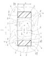
- FIG. 7 is a cross section corresponding to line 7-7 in FIG. 5B in a state where the gate 38 is penetrated to the through hole 27.
- the pair of opposing feet 38a of the gate 38 is in the through hole 27, the outer side surface 39d abuts on the short side 27a of the through hole 27, and the end face 39c abuts on the long side 27b.
- the gate 38 and the through hole 27, that is, the front cowl 15 and the rear cowl 16 are positioned so as not to move relative to each other in the X and Y directions.
- the short side 39a has a length corresponding to the thickness t1
- the long side 39b has a length corresponding to D2.
- a clip 40 is formed to a connection space 38 c (a space between the inner surface 26 b of the flange 26 and the bridge portion 38 b in the inner space of the gate 38) formed by the gate 38 projecting through the through hole 27.
- the clip 40 abuts against both the bridge portion 38 b and the inner surface 26 b of the flange 26 in the vicinity of the long side 27 b of the through hole 27, whereby the gate 38 is prevented from coming off with respect to the through hole 27. It becomes.
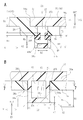
- the clip 40 is a small clip made of resin, and has a substantially quadrilateral peripheral frame portion 41 and a pair of wing portions 42 integrally extending in opposite directions at diagonal positions thereof. Further, among the end surfaces of the peripheral frame portion 41, the bridge portion 38b side is used as a fastening surface 43, and the surface overlapping the inner surface 26b on the opposite flange 26 side is used as a seat surface 44.
- the fastening surface 43 varies in height and comprises a lowest portion 43a and a top portion 43b which is the highest portion.
- the bearing surface 44 forms a flat surface abutting on the inner surface 26 b of the flange 26.
- the clip 40 is turned (turned) between a fixed position (shown state) and an inserted position (not shown), which is a position obtained by rotating it about 90 degrees counterclockwise in the illustrated plane. It has become.
- the peripheral frame portion 41 includes four sides 41a, 41b, 41c and 41d, and the sides 41a and 41c and 41b and 41d face each other in pairs.
- the sides 41a and 41c are outside the gate 38 adjacent to the outside of the pair of long sides 27b.
- the other pair of sides 41 b and 41 d respectively enter the inside of the pair of foot portions 38 a which is the inside of the gate 38.
- One wing portion 42 extends from the side 41a to the left side of the drawing in a direction substantially parallel to the long side 27b, and one side (for example, the drawing) of the end face 39c in the foot 38a on one side (for example, the left side in the drawing) It is in contact with the lower side).
- one end of the adjacent side 41d is continuous via the wing portion 42, and the right side of the side 41a is continuous to the other side 41b adjacent to the rounded portion 43c.
- the opposite side 41c forms a target structure
- the wing portion 42 extends from the side (for example, the right side of the figure) connected to one adjacent side 41b to the right side of the figure, for example, the end face of the foot 38a on the right side of the figure It is in contact with one side (for example, the upper side of the figure) of 39c.
- the other side 41d adjacent to the side 41c is continuous at the rounded portion 43c.
- the lowest portion 43a of the fastening surface 43 is provided on the sides 41a and 41c.
- the tops 43b are provided on the sides 41b and 41d and are adjacent to the foot 38a of the clip 40 and abut on the inner surface (the surface on the connection space 38c side) of the bridge 38b at the fixed position of the clip 40.
- An engagement rib 45 is integrally provided on the inner side of the sides 41a and 41c. The engagement rib 45 protrudes from the seat surface 44 into the through hole 27 at a fixed position of the clip 40 and engages with the inner surface 27 c on the long side 27 b side facing the through hole 27 of the flange 26.
- FIG. 8 shows the gate 38 and the through hole 27 in the same cross section in FIG. 5A in a separated state.
- the clip 40 is inserted into the connection space 38 c.
- the clip 40 is in the insertion position, the extension direction of the wing 42 is parallel to the X direction, and the wing 42 is at the head, and inserted into the connecting space 38 c from the direction orthogonal to the long side 27 b of the through hole 27 .
- the height H4 of the clip 40 (the distance between the highest portion of the wing portion 42 and the seat surface 44) is the height of the bridge portion 38b and the flange 26 (ie, the insertion opening Since the width is larger than the opening width H3, as shown in FIG. 8, the wing portion 42 is inclined and inserted into the connection space 38c, the engagement rib 45 is inserted into the connection space 38c, and 42a and the inner surface 26b of the flange 26 are parallel.
- the clip 40 is rotated approximately 90 degrees to stop rotation.
- Such a detent-type clip is called a turn clip.
- the tank cowl 14 is divided back and forth to form a first cowl 15 and a second cowl 16, which are connected by a connecting portion 14b arranged in the vertical direction, and the alignment line 14a is approximately the cylinder axis CL
- the upper alignment line 14c was inclined so as to diagonally intersect the cylinder axis CL.
- bolts 22, 24, 32 was provided above and below the connection part 14b.
- the tank cowl 14 back and forth, it is possible to replace only the rear cowl 16, which is a knee grip portion that is easily scratched, and the coupling portion 14b can be positioned at a good position while having a cowl fastening structure that can withstand traveling wind. It can be arranged.
- the rotation of the first cowl 15 and the second cowl 16 can be more reliably prevented, and the stress on the connecting portion 14 b can be further reduced.
- first cowl 15 and the second cowl 16 are fastened to the vehicle by the bolts 22, 24 and 32, respectively, so that the first cowl 15 and the second cowl 16 are prevented from relatively rotating due to the wind pressure of the traveling wind
- the stress applied to the connection portion 14 b can be reduced. Therefore, the connecting portion 14 b and the clip 40 can also be miniaturized.
- the fastening of the first cowl and the second cowl can be made good by screw fastening or plug fastening.
- the connecting portion 14b is formed of a rectangular through hole 27 and a U-shaped gate 38 penetrating the through hole 27.
- the long side 27b of the through hole 27 is aligned parallel to the alignment line 14a or 14c, and the gate 38 is penetrated.
- a pair of foot portions 38 a of the gate 38 is made to abut on the pair of opposed short sides 27 a of the through hole 27 by penetrating the hole 27. For this reason, the first cowl 15 and the second cowl 16 can be positioned so as not to be relatively movable in the X and Y directions.
- the connecting portion 14b consisting of the through hole 27 and the gate 38 can be miniaturized and a simple connection structure can be obtained.
- the long side 27b of the through hole 27 is disposed in parallel with the steps 28 and 28a, so that the width of the flange 26 can be narrowed. Since the overlapping portion can be reduced, the first cowl 15 and the second cowl 16 can be miniaturized.
- the clip 40 can be miniaturized.
- the connecting portion 14 b tends to shift in the Y direction of FIG. 7.
- the long side 27b of the through hole 27 is disposed in parallel with the Y direction, and the primary vibration is received by the surface of the foot 38a of the gate 38 by the side 39d of the foot 38a contacting the short side 27a.
- the alignment line 14a is disposed in parallel with the Y direction even if there is a displacement in the Y direction, it is possible to prevent the deformation of the connecting portion 14b that would cause the alignment portion to open. Since the alignment line 14 c is inclined with respect to the Y direction, the deviation tends to occur also in the direction orthogonal to the long side 27 b of the through hole 27. However, in this case, the end face 39 c of the foot 38 a is blocked by coming into contact with the long side 27 b of the through hole 27. Further, the shift in the direction of the long side 27b is prevented by the contact of the side surface 39d of the foot 38a with the short side 27a.
- the front portion 30 is fitted into the recess 25 and pressed in the direction of the alignment line 14c. For this reason, it is possible to prevent the deformation of the connecting portion 14b such that the joint portion is opened also at the joint line 14c.
- the engagement rib 45 also abuts the through hole inner surface 26c at the long side 27b and slides against the through hole inner surface 26c, so that the wear of the engagement rib 45 is reduced.
- the engagement rib 45 is a member for preventing movement of a longitudinal middle portion of the long side 27b of the through hole 27 which is not in contact with the foot portion 38a, but is provided temporarily on the short side 27a side orthogonal to the Y direction. Also, since the friction between the short side 27a and the engagement rib 45 due to vibration increases and wears in a relatively short time, it is necessary to replace the clip 40 itself in a relatively short time. However, by arranging the engagement rib 45 on the long side 27 b side, such wear can be reduced, and the durability of the clip 40 can be enhanced to lengthen the replacement cycle.
- the through hole 27 is rectangular and the long side 27 b is provided, the movement in the longitudinal middle portion of the long side 27 b can be blocked by the engagement rib 45, and thus the clip 40 having the engagement rib 45 The use itself of the rectangular through hole 27 can be enabled.
- the connecting portion 14b when receiving a large external force in the direction to open the connecting portion 14b, ie, receiving a force in the direction orthogonal to the mating lines 14a and 14c, the end face 39c of the foot 38a abuts on the long side 27b of the through hole 27, This force can be received by the long side 27b, and the shift in the direction in which the connecting portion 14b opens can be prevented. Therefore, even if a large external force is applied to the tank cowl 14 and a force acts in the direction of opening the connecting portion 14b, the connecting portion 14b can be made difficult to open. Furthermore, the stress applied to the through hole 27 can be reduced by receiving the end face 39c of the foot 38a by the long side 27b.
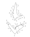
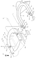
- FIG. 9 shows the connection structure of the left and right under cowls.
- the part common to previous embodiment uses a common code
- This embodiment relates to the mounting of the under cowl 54 not used in the vehicle of the previous embodiment.
- the under cowl 54 is a vehicle body cover that covers the side and the lower side of the engine 8 in a substantially U-shaped cross section, is formed separately on the left and right, and connects the left cover 55 and the right cover 56 under the engine 8 .
- the left cover 55 and the right cover 56 correspond to the first member and the second member of the present invention, respectively.
- the clip 50 can be connected in the same manner as in the previous embodiment.
- the through hole 57, the gate 58, and the clip 50 are configured as in the previous embodiment.
- the through hole 57 is provided along the long line direction of the left cover 55 and the right cover 56 along the long side direction.
- the mating line 51 extends in the longitudinal direction of the vehicle parallel to the vehicle body center C (in FIG. 9, the vehicle body center C is a vertical line, but in plan view, it is a straight line extending horizontally in the longitudinal direction).
- the left cover 55 and the right cover 56 are fastened to the stay 52 on the vehicle body side by bolts 53 and nuts 53 a on the left and right of the engine 8 above the connecting portion 59.
- the bolt 53 is an implantation bolt which is integrated in advance to the left cover 55 and the right cover 56, and this bolt is penetrated to one end of the stay 52 and fastened with a nut 53a.
- the other end of the stay 52 is attached to the vehicle body frame. In this case, by fastening the upper portion of the under cowl 54, the mass of the under cowl 54 can be configured not to be applied to the connecting portion 59.
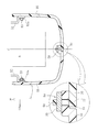
- FIG. 10 is yet another embodiment, and relates to the mounting structure of the taillight assembly.
- the first member is a luggage box 60 disposed below the seat 10
- the second member is a taillight assembly 61 provided at the rear of the vehicle body.
- the taillight assembly 61 is provided with a taillight 63, which is a safety part, behind a substantially U-shaped mounting portion 62, and a license plate 64 is integrally provided below the taillight 63 and can be removed. There is.
- the luggage box 60 is integrally provided with a rear fender 65 (FIG. 1) disposed so as to cover the upper side of the rear wheel 13 and opened upward, so that articles can be taken in and out by opening the sheet 10. It is fastened on the pair of left and right seat rails 11 by bolts 66. Through holes 67 are formed on the left and right behind the fastening portion by the bolt 66.
- the through hole 67 has a rectangular shape, and is disposed with the long side direction in the left and right direction.
- the mounting portions 62 are provided in a pair corresponding to the left and right seat rails 11, and each has a U-shaped cross section released downward, and is attached to the seat rail 11 in a plug-in manner. It is fastened by an appropriate fastening member. Further, a gate 68 is integrally formed on the upper surface of the mounting portion 62 so as to protrude upward.
- the taillight assembly 61 can be easily moved to the luggage box 60. It is connected. Further, the clip 70 can be removed to separate it from the luggage box 60, and the fastening of the mounting portion 62 to the seat rail 11 can be removed easily and quickly from the seat rail 11. Therefore, it is suitable for a race-spec car that does not require the taillight assembly 61 during a race.
- the taillight assembly 61 is heavy and vibrates in the vertical direction.
- the weight is supported by the seat rail 11 and the longitudinal direction of the through hole 67 is arranged in the left and right direction, the end face 68 c of the foot 68 a passes through the through hole 67 if the gate 68 tries to shift up and down.
- the stress applied to the through hole 67 can be reduced by abutting on the long side 67 b to prevent the displacement and receiving the foot portion 68 a at the long side 67 b. For this reason, it is possible to stably connect members that vibrate in the vertical direction with a heavy weight such as the taillight assembly 61.
- the connecting portion 69 of the luggage box 60 and the taillight assembly 61 can be covered and concealed, making it possible to make the safety parts less likely to be tampered with.
- the present invention is not limited to the above-described embodiments, and various modifications and applications are possible within the principle of the invention.
- the target to which the present invention is applied is not limited to the above examples, as long as it is a first member and a second member that are mutually connected and fastened to a vehicle.
- the saddle-ride type vehicle to which the present invention is applied can be any of an automatic two- to four-wheeled vehicle, etc.
- the application may be any of on-road, off-road, racing and the like.
Landscapes
- Engineering & Computer Science (AREA)
- Mechanical Engineering (AREA)
- Body Structure For Vehicles (AREA)
- Connection Of Plates (AREA)
- Automatic Cycles, And Cycles In General (AREA)
- Clamps And Clips (AREA)
Priority Applications (4)
| Application Number | Priority Date | Filing Date | Title |
|---|---|---|---|
| EP13842345.4A EP2902304B1 (en) | 2012-09-28 | 2013-09-26 | Connecting structure of vehicle component parts |
| US14/431,041 US9944341B2 (en) | 2012-09-28 | 2013-09-26 | Connecting structure of vehicle component parts |
| BR112015006348-9A BR112015006348B1 (pt) | 2012-09-28 | 2013-09-26 | Estrutura de conexão de partes componentes de veículo |
| CN201380050820.5A CN104684797B (zh) | 2012-09-28 | 2013-09-26 | 车辆部件的连接结构 |
Applications Claiming Priority (2)
| Application Number | Priority Date | Filing Date | Title |
|---|---|---|---|
| JP2012218269A JP5864392B2 (ja) | 2012-09-28 | 2012-09-28 | 車両部品の連結構造 |
| JP2012-218269 | 2012-09-28 |
Publications (1)
| Publication Number | Publication Date |
|---|---|
| WO2014051012A1 true WO2014051012A1 (ja) | 2014-04-03 |
Family
ID=50388407
Family Applications (1)
| Application Number | Title | Priority Date | Filing Date |
|---|---|---|---|
| PCT/JP2013/076160 Ceased WO2014051012A1 (ja) | 2012-09-28 | 2013-09-26 | 車両部品の連結構造 |
Country Status (6)
| Country | Link |
|---|---|
| US (1) | US9944341B2 (enExample) |
| EP (1) | EP2902304B1 (enExample) |
| JP (1) | JP5864392B2 (enExample) |
| CN (1) | CN104684797B (enExample) |
| BR (1) | BR112015006348B1 (enExample) |
| WO (1) | WO2014051012A1 (enExample) |
Cited By (1)
| Publication number | Priority date | Publication date | Assignee | Title |
|---|---|---|---|---|
| EP3098148A1 (en) * | 2015-05-27 | 2016-11-30 | Honda Motor Co., Ltd. | Straddle-type vehicle |
Families Citing this family (2)
| Publication number | Priority date | Publication date | Assignee | Title |
|---|---|---|---|---|
| JP6798974B2 (ja) * | 2017-12-28 | 2020-12-09 | 本田技研工業株式会社 | 車両用樹脂部品 |
| US20230103828A1 (en) * | 2021-10-01 | 2023-04-06 | Kawasaki Motors, Ltd. | Saddle riding vehicle |
Citations (6)
| Publication number | Priority date | Publication date | Assignee | Title |
|---|---|---|---|---|
| JPH1159535A (ja) * | 1997-08-25 | 1999-03-02 | Yamaha Motor Co Ltd | 自動二輪車のアンダーカウル構造 |
| JP2007530355A (ja) | 2004-03-31 | 2007-11-01 | バイエリッシェ モートーレン ウエルケ アクチエンゲゼルシャフト | オートバイフェアリング |
| JP2010274850A (ja) * | 2009-05-29 | 2010-12-09 | Suzuki Motor Corp | 自動二輪車のフレームカバー取付構造。 |
| WO2011065121A1 (ja) * | 2009-11-30 | 2011-06-03 | トヨタ車体株式会社 | クリップ |
| JP2011152847A (ja) * | 2010-01-27 | 2011-08-11 | Honda Motor Co Ltd | 鞍乗型車両の力ウリング構造 |
| JP2013228068A (ja) * | 2012-04-26 | 2013-11-07 | Nifco Inc | クリップ |
Family Cites Families (15)
| Publication number | Priority date | Publication date | Assignee | Title |
|---|---|---|---|---|
| US1021185A (en) * | 1912-02-15 | 1912-03-26 | Foster Brothers Mfg Co | Corner-fastening for bedsteads. |
| US2870667A (en) * | 1954-07-08 | 1959-01-27 | American Brake Shoe Co | Retaining key for dipper tooth parts having resilient pad |
| US4331358A (en) * | 1980-06-09 | 1982-05-25 | First Champaign Corporation | Motorcycle fairing body extender |
| JP2515897Y2 (ja) * | 1991-04-08 | 1996-10-30 | 日野自動車工業株式会社 | フランジ付部材の連結構造 |
| JP2754139B2 (ja) * | 1993-10-19 | 1998-05-20 | 本田技研工業株式会社 | スクータ型車両の前部車体カバー |
| JPH11171072A (ja) * | 1997-12-09 | 1999-06-29 | Yamaha Motor Co Ltd | 自動二輪車用テールカウリング |
| US5897278A (en) * | 1998-02-05 | 1999-04-27 | Southco, Inc. | Turn fastener |
| JP4531613B2 (ja) * | 2005-03-31 | 2010-08-25 | 本田技研工業株式会社 | 車輌のカウル構造 |
| JP5178430B2 (ja) * | 2008-09-26 | 2013-04-10 | 本田技研工業株式会社 | 車両用フロントカバーの締結部構造 |
| JP5305104B2 (ja) | 2009-09-12 | 2013-10-02 | 株式会社リコー | ベルト駆動装置、及び、画像形成装置 |
| WO2012064694A1 (en) * | 2010-11-09 | 2012-05-18 | Illinois Tool Works Inc. | Bracket clip |
| JP5730129B2 (ja) * | 2011-05-27 | 2015-06-03 | 本田技研工業株式会社 | カウル締結構造 |
| JP5725503B2 (ja) * | 2011-07-11 | 2015-05-27 | 本田技研工業株式会社 | 鞍乗り型車両の外装部材 |
| JP5764522B2 (ja) * | 2012-04-26 | 2015-08-19 | 本田技研工業株式会社 | クリップ |
| JP5864391B2 (ja) * | 2012-09-28 | 2016-02-17 | 株式会社ニフコ | クリップ |
-
2012
- 2012-09-28 JP JP2012218269A patent/JP5864392B2/ja not_active Expired - Fee Related
-
2013
- 2013-09-26 WO PCT/JP2013/076160 patent/WO2014051012A1/ja not_active Ceased
- 2013-09-26 BR BR112015006348-9A patent/BR112015006348B1/pt not_active IP Right Cessation
- 2013-09-26 EP EP13842345.4A patent/EP2902304B1/en not_active Not-in-force
- 2013-09-26 CN CN201380050820.5A patent/CN104684797B/zh not_active Expired - Fee Related
- 2013-09-26 US US14/431,041 patent/US9944341B2/en active Active
Patent Citations (6)
| Publication number | Priority date | Publication date | Assignee | Title |
|---|---|---|---|---|
| JPH1159535A (ja) * | 1997-08-25 | 1999-03-02 | Yamaha Motor Co Ltd | 自動二輪車のアンダーカウル構造 |
| JP2007530355A (ja) | 2004-03-31 | 2007-11-01 | バイエリッシェ モートーレン ウエルケ アクチエンゲゼルシャフト | オートバイフェアリング |
| JP2010274850A (ja) * | 2009-05-29 | 2010-12-09 | Suzuki Motor Corp | 自動二輪車のフレームカバー取付構造。 |
| WO2011065121A1 (ja) * | 2009-11-30 | 2011-06-03 | トヨタ車体株式会社 | クリップ |
| JP2011152847A (ja) * | 2010-01-27 | 2011-08-11 | Honda Motor Co Ltd | 鞍乗型車両の力ウリング構造 |
| JP2013228068A (ja) * | 2012-04-26 | 2013-11-07 | Nifco Inc | クリップ |
Cited By (3)
| Publication number | Priority date | Publication date | Assignee | Title |
|---|---|---|---|---|
| EP3098148A1 (en) * | 2015-05-27 | 2016-11-30 | Honda Motor Co., Ltd. | Straddle-type vehicle |
| AU2016202174B2 (en) * | 2015-05-27 | 2018-02-22 | Honda Motor Co., Ltd. | Saddle-riding type vehicle |
| US9944342B2 (en) | 2015-05-27 | 2018-04-17 | Honda Motor Co., Ltd. | Straddle-type vehicle |
Also Published As
| Publication number | Publication date |
|---|---|
| CN104684797A (zh) | 2015-06-03 |
| EP2902304A4 (en) | 2016-06-01 |
| BR112015006348A2 (pt) | 2017-07-04 |
| EP2902304B1 (en) | 2017-10-04 |
| US20150239519A1 (en) | 2015-08-27 |
| BR112015006348B1 (pt) | 2021-06-29 |
| CN104684797B (zh) | 2017-08-11 |
| JP5864392B2 (ja) | 2016-02-17 |
| JP2014069733A (ja) | 2014-04-21 |
| US9944341B2 (en) | 2018-04-17 |
| EP2902304A1 (en) | 2015-08-05 |
Similar Documents
| Publication | Publication Date | Title |
|---|---|---|
| CN102161362B (zh) | 跨骑型车辆 | |
| EP3398844B1 (en) | Mudguard member for saddled vehicle | |
| CN105658509B (zh) | 跨乘式车辆的车身框架结构 | |
| JP2011245897A (ja) | 自動二輪車 | |
| WO2014051012A1 (ja) | 車両部品の連結構造 | |
| CN101868401B (zh) | 骑乘型车辆 | |
| JP6224262B2 (ja) | 鞍乗り型車両のフロントフェンダ構造 | |
| JP2017077805A (ja) | 自動二輪車の燃料タンク構造 | |
| JP4991363B2 (ja) | 自動二輪車のカウル構造 | |
| EP3088284B1 (en) | Straddled vehicle | |
| CN101817376B (zh) | 跨骑型车辆 | |
| JP3934753B2 (ja) | 自動二輪車のアンダーカウル構造 | |
| JP2014034242A (ja) | 自動二輪車のサイドカウル構造 | |
| JP6783939B2 (ja) | 車体フレーム構造 | |
| JP7061051B2 (ja) | 鞍乗型車両の後部構造 | |
| JP7436572B2 (ja) | フロントカバー | |
| JP5911175B2 (ja) | 鞍乗り型車両の後部構造 | |
| JP5576306B2 (ja) | 鞍乗り型車両の前部構造 | |
| JP4584825B2 (ja) | ブレーキペダル組み付け構造 | |
| US7802841B2 (en) | Straddle type vehicle | |
| JP6697128B2 (ja) | 鞍乗り型車両 | |
| EP2783957A1 (en) | Saddle type vehicle | |
| CN105764783B (zh) | 跨骑型车辆 | |
| JP2012183896A (ja) | 鞍乗り型車両 |
Legal Events
| Date | Code | Title | Description |
|---|---|---|---|
| 121 | Ep: the epo has been informed by wipo that ep was designated in this application |
Ref document number: 13842345 Country of ref document: EP Kind code of ref document: A1 |
|
| REEP | Request for entry into the european phase |
Ref document number: 2013842345 Country of ref document: EP |
|
| WWE | Wipo information: entry into national phase |
Ref document number: 2013842345 Country of ref document: EP |
|
| WWE | Wipo information: entry into national phase |
Ref document number: IDP00201501707 Country of ref document: ID |
|
| WWE | Wipo information: entry into national phase |
Ref document number: 14431041 Country of ref document: US |
|
| NENP | Non-entry into the national phase |
Ref country code: DE |
|
| REG | Reference to national code |
Ref country code: BR Ref legal event code: B01A Ref document number: 112015006348 Country of ref document: BR |
|
| ENP | Entry into the national phase |
Ref document number: 112015006348 Country of ref document: BR Kind code of ref document: A2 Effective date: 20150323 |