WO2014050593A1 - 無段変速装置 - Google Patents
無段変速装置 Download PDFInfo
- Publication number
- WO2014050593A1 WO2014050593A1 PCT/JP2013/074711 JP2013074711W WO2014050593A1 WO 2014050593 A1 WO2014050593 A1 WO 2014050593A1 JP 2013074711 W JP2013074711 W JP 2013074711W WO 2014050593 A1 WO2014050593 A1 WO 2014050593A1
- Authority
- WO
- WIPO (PCT)
- Prior art keywords
- hydraulic pressure
- valve
- opening degree
- continuously variable
- variable transmission
- Prior art date
- Legal status (The legal status is an assumption and is not a legal conclusion. Google has not performed a legal analysis and makes no representation as to the accuracy of the status listed.)
- Ceased
Links
Images



Classifications
-
- F—MECHANICAL ENGINEERING; LIGHTING; HEATING; WEAPONS; BLASTING
- F16—ENGINEERING ELEMENTS AND UNITS; GENERAL MEASURES FOR PRODUCING AND MAINTAINING EFFECTIVE FUNCTIONING OF MACHINES OR INSTALLATIONS; THERMAL INSULATION IN GENERAL
- F16H—GEARING
- F16H61/00—Control functions within control units of change-speed- or reversing-gearings for conveying rotary motion ; Control of exclusively fluid gearing, friction gearing, gearings with endless flexible members or other particular types of gearing
- F16H61/02—Control functions within control units of change-speed- or reversing-gearings for conveying rotary motion ; Control of exclusively fluid gearing, friction gearing, gearings with endless flexible members or other particular types of gearing characterised by the signals used
- F16H61/0262—Control functions within control units of change-speed- or reversing-gearings for conveying rotary motion ; Control of exclusively fluid gearing, friction gearing, gearings with endless flexible members or other particular types of gearing characterised by the signals used the signals being hydraulic
-
- F—MECHANICAL ENGINEERING; LIGHTING; HEATING; WEAPONS; BLASTING
- F16—ENGINEERING ELEMENTS AND UNITS; GENERAL MEASURES FOR PRODUCING AND MAINTAINING EFFECTIVE FUNCTIONING OF MACHINES OR INSTALLATIONS; THERMAL INSULATION IN GENERAL
- F16H—GEARING
- F16H61/00—Control functions within control units of change-speed- or reversing-gearings for conveying rotary motion ; Control of exclusively fluid gearing, friction gearing, gearings with endless flexible members or other particular types of gearing
- F16H61/66—Control functions within control units of change-speed- or reversing-gearings for conveying rotary motion ; Control of exclusively fluid gearing, friction gearing, gearings with endless flexible members or other particular types of gearing specially adapted for continuously variable gearings
- F16H61/664—Friction gearings
-
- F—MECHANICAL ENGINEERING; LIGHTING; HEATING; WEAPONS; BLASTING
- F16—ENGINEERING ELEMENTS AND UNITS; GENERAL MEASURES FOR PRODUCING AND MAINTAINING EFFECTIVE FUNCTIONING OF MACHINES OR INSTALLATIONS; THERMAL INSULATION IN GENERAL
- F16H—GEARING
- F16H61/00—Control functions within control units of change-speed- or reversing-gearings for conveying rotary motion ; Control of exclusively fluid gearing, friction gearing, gearings with endless flexible members or other particular types of gearing
- F16H61/66—Control functions within control units of change-speed- or reversing-gearings for conveying rotary motion ; Control of exclusively fluid gearing, friction gearing, gearings with endless flexible members or other particular types of gearing specially adapted for continuously variable gearings
- F16H61/664—Friction gearings
- F16H61/6648—Friction gearings controlling of shifting being influenced by a signal derived from the engine and the main coupling
-
- F—MECHANICAL ENGINEERING; LIGHTING; HEATING; WEAPONS; BLASTING
- F16—ENGINEERING ELEMENTS AND UNITS; GENERAL MEASURES FOR PRODUCING AND MAINTAINING EFFECTIVE FUNCTIONING OF MACHINES OR INSTALLATIONS; THERMAL INSULATION IN GENERAL
- F16H—GEARING
- F16H15/00—Gearings for conveying rotary motion with variable gear ratio, or for reversing rotary motion, by friction between rotary members
- F16H15/02—Gearings for conveying rotary motion with variable gear ratio, or for reversing rotary motion, by friction between rotary members without members having orbital motion
- F16H15/04—Gearings providing a continuous range of gear ratios
- F16H15/06—Gearings providing a continuous range of gear ratios in which a member A of uniform effective diameter mounted on a shaft may co-operate with different parts of a member B
- F16H15/32—Gearings providing a continuous range of gear ratios in which a member A of uniform effective diameter mounted on a shaft may co-operate with different parts of a member B in which the member B has a curved friction surface formed as a surface of a body of revolution generated by a curve which is neither a circular arc centered on its axis of revolution nor a straight line
- F16H15/36—Gearings providing a continuous range of gear ratios in which a member A of uniform effective diameter mounted on a shaft may co-operate with different parts of a member B in which the member B has a curved friction surface formed as a surface of a body of revolution generated by a curve which is neither a circular arc centered on its axis of revolution nor a straight line with concave friction surface, e.g. a hollow toroid surface
- F16H15/38—Gearings providing a continuous range of gear ratios in which a member A of uniform effective diameter mounted on a shaft may co-operate with different parts of a member B in which the member B has a curved friction surface formed as a surface of a body of revolution generated by a curve which is neither a circular arc centered on its axis of revolution nor a straight line with concave friction surface, e.g. a hollow toroid surface with two members B having hollow toroid surfaces opposite to each other, the member or members A being adjustably mounted between the surfaces
-
- F—MECHANICAL ENGINEERING; LIGHTING; HEATING; WEAPONS; BLASTING
- F16—ENGINEERING ELEMENTS AND UNITS; GENERAL MEASURES FOR PRODUCING AND MAINTAINING EFFECTIVE FUNCTIONING OF MACHINES OR INSTALLATIONS; THERMAL INSULATION IN GENERAL
- F16H—GEARING
- F16H37/00—Combinations of mechanical gearings, not provided for in groups F16H1/00 - F16H35/00
- F16H37/02—Combinations of mechanical gearings, not provided for in groups F16H1/00 - F16H35/00 comprising essentially only toothed or friction gearings
- F16H37/021—Combinations of mechanical gearings, not provided for in groups F16H1/00 - F16H35/00 comprising essentially only toothed or friction gearings toothed gearing combined with continuously variable friction gearing
-
- F—MECHANICAL ENGINEERING; LIGHTING; HEATING; WEAPONS; BLASTING
- F16—ENGINEERING ELEMENTS AND UNITS; GENERAL MEASURES FOR PRODUCING AND MAINTAINING EFFECTIVE FUNCTIONING OF MACHINES OR INSTALLATIONS; THERMAL INSULATION IN GENERAL
- F16H—GEARING
- F16H37/00—Combinations of mechanical gearings, not provided for in groups F16H1/00 - F16H35/00
- F16H37/02—Combinations of mechanical gearings, not provided for in groups F16H1/00 - F16H35/00 comprising essentially only toothed or friction gearings
- F16H37/06—Combinations of mechanical gearings, not provided for in groups F16H1/00 - F16H35/00 comprising essentially only toothed or friction gearings with a plurality of driving or driven shafts; with arrangements for dividing torque between two or more intermediate shafts
- F16H37/08—Combinations of mechanical gearings, not provided for in groups F16H1/00 - F16H35/00 comprising essentially only toothed or friction gearings with a plurality of driving or driven shafts; with arrangements for dividing torque between two or more intermediate shafts with differential gearing
- F16H37/0806—Combinations of mechanical gearings, not provided for in groups F16H1/00 - F16H35/00 comprising essentially only toothed or friction gearings with a plurality of driving or driven shafts; with arrangements for dividing torque between two or more intermediate shafts with differential gearing with a plurality of driving or driven shafts
- F16H37/0826—Combinations of mechanical gearings, not provided for in groups F16H1/00 - F16H35/00 comprising essentially only toothed or friction gearings with a plurality of driving or driven shafts; with arrangements for dividing torque between two or more intermediate shafts with differential gearing with a plurality of driving or driven shafts with only one output shaft
-
- F—MECHANICAL ENGINEERING; LIGHTING; HEATING; WEAPONS; BLASTING
- F16—ENGINEERING ELEMENTS AND UNITS; GENERAL MEASURES FOR PRODUCING AND MAINTAINING EFFECTIVE FUNCTIONING OF MACHINES OR INSTALLATIONS; THERMAL INSULATION IN GENERAL
- F16H—GEARING
- F16H61/00—Control functions within control units of change-speed- or reversing-gearings for conveying rotary motion ; Control of exclusively fluid gearing, friction gearing, gearings with endless flexible members or other particular types of gearing
- F16H61/0021—Generation or control of line pressure
-
- F—MECHANICAL ENGINEERING; LIGHTING; HEATING; WEAPONS; BLASTING
- F16—ENGINEERING ELEMENTS AND UNITS; GENERAL MEASURES FOR PRODUCING AND MAINTAINING EFFECTIVE FUNCTIONING OF MACHINES OR INSTALLATIONS; THERMAL INSULATION IN GENERAL
- F16H—GEARING
- F16H61/00—Control functions within control units of change-speed- or reversing-gearings for conveying rotary motion ; Control of exclusively fluid gearing, friction gearing, gearings with endless flexible members or other particular types of gearing
- F16H61/02—Control functions within control units of change-speed- or reversing-gearings for conveying rotary motion ; Control of exclusively fluid gearing, friction gearing, gearings with endless flexible members or other particular types of gearing characterised by the signals used
- F16H61/0262—Control functions within control units of change-speed- or reversing-gearings for conveying rotary motion ; Control of exclusively fluid gearing, friction gearing, gearings with endless flexible members or other particular types of gearing characterised by the signals used the signals being hydraulic
- F16H61/0265—Control functions within control units of change-speed- or reversing-gearings for conveying rotary motion ; Control of exclusively fluid gearing, friction gearing, gearings with endless flexible members or other particular types of gearing characterised by the signals used the signals being hydraulic for gearshift control, e.g. control functions for performing shifting or generation of shift signals
-
- F—MECHANICAL ENGINEERING; LIGHTING; HEATING; WEAPONS; BLASTING
- F16—ENGINEERING ELEMENTS AND UNITS; GENERAL MEASURES FOR PRODUCING AND MAINTAINING EFFECTIVE FUNCTIONING OF MACHINES OR INSTALLATIONS; THERMAL INSULATION IN GENERAL
- F16H—GEARING
- F16H61/00—Control functions within control units of change-speed- or reversing-gearings for conveying rotary motion ; Control of exclusively fluid gearing, friction gearing, gearings with endless flexible members or other particular types of gearing
- F16H61/02—Control functions within control units of change-speed- or reversing-gearings for conveying rotary motion ; Control of exclusively fluid gearing, friction gearing, gearings with endless flexible members or other particular types of gearing characterised by the signals used
- F16H61/0262—Control functions within control units of change-speed- or reversing-gearings for conveying rotary motion ; Control of exclusively fluid gearing, friction gearing, gearings with endless flexible members or other particular types of gearing characterised by the signals used the signals being hydraulic
- F16H61/0276—Elements specially adapted for hydraulic control units, e.g. valves
-
- F—MECHANICAL ENGINEERING; LIGHTING; HEATING; WEAPONS; BLASTING
- F16—ENGINEERING ELEMENTS AND UNITS; GENERAL MEASURES FOR PRODUCING AND MAINTAINING EFFECTIVE FUNCTIONING OF MACHINES OR INSTALLATIONS; THERMAL INSULATION IN GENERAL
- F16H—GEARING
- F16H61/00—Control functions within control units of change-speed- or reversing-gearings for conveying rotary motion ; Control of exclusively fluid gearing, friction gearing, gearings with endless flexible members or other particular types of gearing
- F16H61/04—Smoothing ratio shift
- F16H61/06—Smoothing ratio shift by controlling rate of change of fluid pressure
- F16H61/061—Smoothing ratio shift by controlling rate of change of fluid pressure using electric control means
-
- F—MECHANICAL ENGINEERING; LIGHTING; HEATING; WEAPONS; BLASTING
- F16—ENGINEERING ELEMENTS AND UNITS; GENERAL MEASURES FOR PRODUCING AND MAINTAINING EFFECTIVE FUNCTIONING OF MACHINES OR INSTALLATIONS; THERMAL INSULATION IN GENERAL
- F16H—GEARING
- F16H61/00—Control functions within control units of change-speed- or reversing-gearings for conveying rotary motion ; Control of exclusively fluid gearing, friction gearing, gearings with endless flexible members or other particular types of gearing
- F16H61/66—Control functions within control units of change-speed- or reversing-gearings for conveying rotary motion ; Control of exclusively fluid gearing, friction gearing, gearings with endless flexible members or other particular types of gearing specially adapted for continuously variable gearings
- F16H61/664—Friction gearings
- F16H61/6649—Friction gearings characterised by the means for controlling the torque transmitting capability of the gearing
-
- F—MECHANICAL ENGINEERING; LIGHTING; HEATING; WEAPONS; BLASTING
- F16—ENGINEERING ELEMENTS AND UNITS; GENERAL MEASURES FOR PRODUCING AND MAINTAINING EFFECTIVE FUNCTIONING OF MACHINES OR INSTALLATIONS; THERMAL INSULATION IN GENERAL
- F16H—GEARING
- F16H61/00—Control functions within control units of change-speed- or reversing-gearings for conveying rotary motion ; Control of exclusively fluid gearing, friction gearing, gearings with endless flexible members or other particular types of gearing
- F16H61/02—Control functions within control units of change-speed- or reversing-gearings for conveying rotary motion ; Control of exclusively fluid gearing, friction gearing, gearings with endless flexible members or other particular types of gearing characterised by the signals used
- F16H61/0202—Control functions within control units of change-speed- or reversing-gearings for conveying rotary motion ; Control of exclusively fluid gearing, friction gearing, gearings with endless flexible members or other particular types of gearing characterised by the signals used the signals being electric
- F16H61/0251—Elements specially adapted for electric control units, e.g. valves for converting electrical signals to fluid signals
- F16H2061/0255—Solenoid valve using PWM or duty-cycle control
-
- F—MECHANICAL ENGINEERING; LIGHTING; HEATING; WEAPONS; BLASTING
- F16—ENGINEERING ELEMENTS AND UNITS; GENERAL MEASURES FOR PRODUCING AND MAINTAINING EFFECTIVE FUNCTIONING OF MACHINES OR INSTALLATIONS; THERMAL INSULATION IN GENERAL
- F16H—GEARING
- F16H61/00—Control functions within control units of change-speed- or reversing-gearings for conveying rotary motion ; Control of exclusively fluid gearing, friction gearing, gearings with endless flexible members or other particular types of gearing
- F16H61/04—Smoothing ratio shift
- F16H61/06—Smoothing ratio shift by controlling rate of change of fluid pressure
- F16H61/061—Smoothing ratio shift by controlling rate of change of fluid pressure using electric control means
- F16H2061/062—Smoothing ratio shift by controlling rate of change of fluid pressure using electric control means for controlling filling of clutches or brake servos, e.g. fill time, fill level or pressure during filling
Definitions
- the present invention relates to a continuously variable transmission used as an automatic transmission for a vehicle including an automobile.
- a continuously variable transmission equipped with a toroidal continuously variable transmission is used as an automatic transmission for vehicles including automobiles.
- a toroidal continuously variable transmission and a differential gear unit such as a planetary gear transmission are also combined in order to increase the fluctuation range of the gear ratio.
- Japanese Patent Application Laid-Open No. 2011-174486 and Japanese Patent Application Laid-Open No. 2012-002330 include a so-called geared neutral (GN) state in which the rotation state of the output shaft is stopped while the input shaft is rotated in one direction.
- GN geared neutral
- FIG. 7 and 8 show a conventional continuously variable transmission having a mode capable of realizing a geared neutral state.
- FIG. 7 is a block diagram of the continuously variable transmission
- FIG. 8 shows a hydraulic circuit for controlling the continuously variable transmission.
- the output of the engine 1 is input to the main shaft 3 via the damper 2.
- the power transmitted to the main shaft 3 is transmitted directly or via the toroidal continuously variable transmission 4 to the planetary gear transmission 5 as a differential gear unit.
- the differential component of the constituent members of the planetary gear type transmission 5 is taken out to the output shaft 9 via the clutch device 6 constituted by the low speed clutch 7 and the high speed clutch 8 (see FIG. 8).
- the toroidal continuously variable transmission 4 constituting the continuously variable transmission includes an input disk 10, an output disk 11, a plurality of power rollers 12, a plurality of trunnions (not shown), and an actuator 13 (see FIG. 8). And a pressing device 14 and a gear ratio control unit 15.
- the input disk 10 and the output disk 11 are configured by toroidal curved surfaces, have axial side surfaces facing each other, are concentric with each other, and are relatively It is arranged so that it can rotate.
- Each of the power rollers 12 is rotatably supported by a corresponding trunnion, and is sandwiched between the side surfaces in the axial direction of the input disk 10 and the output disk 11 so that the power is transferred between the input disk 10 and the output disk 10. (Force, torque) is transmitted.
- the actuator 13 is hydraulic, and each trunnion that supports the power roller 12 is displaced in the axial direction of the pivot provided at both ends thereof to change the gear ratio between the input disk 10 and the output disk 11.
- the pressing device 14 is hydraulic and presses the input disk 10 and the output disk 11 in a direction approaching each other.
- the gear ratio control unit 15 controls the displacement direction and the amount of displacement of the actuator 13 in order to set the gear ratio between the input disk 10 and the output disk 11 to a desired value.
- the transmission ratio control unit 15 is switched based on a control unit (ECU) 16 based on a control signal from the controller 16, a stepping motor 17, a line pressure control electromagnetic valve 18, a pressing force control electromagnetic valve 19, and
- the mode switching electromagnetic valve 20 and a control valve device 21 whose operation state can be switched by the stepping motor 17 and the mode switching electromagnetic valve 20 are configured.
- the control valve device 21 includes a transmission ratio control valve 22, a low speed clutch control valve 23, and a high speed clutch control valve 24 (see FIG. 8).
- the transmission ratio control valve 22 controls supply / discharge of pressure oil to / from the actuator 13.
- the low-speed clutch control valve 23 and the high-speed clutch control valve 24 correspond to the mode switching electromagnetic valve 20 and switch the hydraulic pressure introduction state to the low-speed clutch 7 and the high-speed clutch 8.
- the oil supply pump 25 is driven by the power extracted from the damper 2, and the pressure oil discharged from the oil supply pump 25 is sent to the control valve device 21 and the pressing device 14. That is, the pressure oil sucked from the oil reservoir 26 (see FIG. 8) and discharged by the oil supply pump 25 is adjusted to a predetermined pressure by the pressing force adjusting valve 27 (see FIG. 8).
- the pressing force adjusting valve 27 is controlled by a hydraulic pressure corresponding to a hydraulic pressure difference (differential pressure) existing between a pair of hydraulic chambers provided with a piston sandwiched between the actuator 13 and a command from the controller 16.
- the valve opening pressure is adjusted based on the introduction of the hydraulic pressure based on the opening / closing of the line pressure control electromagnetic valve 18. Then, with this valve opening pressure as the maximum value, the pressing force control solenoid valve 19 restricts the pressing force generated by the pressing device 14 to an optimum value according to the operating state at that time.
- the hydraulic pressure adjusted by the line pressure control valve 18 and the pressing force adjustment valve 27 is further adjusted (depressurized) to a predetermined pressure by the pressure reducing valve 28, and the low speed is controlled via the low speed clutch control valve 23 or the high speed clutch control valve 24.
- the clutch 7 or the high-speed clutch 8 is fed into the hydraulic chamber.
- the low speed clutch 7 is connected when realizing a low speed mode in which the reduction ratio is increased or the transmission ratio is infinite (geared / neutral state), and is connected when realizing a high speed mode in which the reduction ratio is reduced. Is refused.
- the high-speed clutch 8 is disconnected when realizing the low-speed mode, and is connected when realizing the high-speed mode.
- the pressure oil supply / discharge state to the low speed clutch 7 and the high speed clutch 8 is switched according to the switching of the mode switching solenoid valve 20.
- the speed ratio (1 / reduction ratio) of the continuously variable transmission as a whole is set to the low speed mode and the high speed mode.
- the speed ratio of the toroidal continuously variable transmission 4 is adjusted so as to be the same.
- the controller 16 receives signals representing the respective rotational speeds of the input disk 10, the output disk 11, and the output shaft 9 detected by the input disk rotation sensor 29, the output disk rotation sensor 30, and the output shaft rotation sensor 31. . Further, the controller 16 exchanges signals with the engine controller 32. Further, the controller 16 receives a shift mode switching signal indicating the connection / disconnection state of the low speed clutch 7 and the high speed clutch 8 and a T / M select position signal indicating the operation position of the select lever. In addition, a paddle shift signal for manual shifting, a foot brake signal indicating whether or not a brake pedal is operated, and an accelerator pedal opening signal indicating the amount of depression of the accelerator pedal are supplied to the controller 16 via the engine controller 32. Entered.
- FIG. 9 shows an example of the relationship between the speed ratio of the toroidal continuously variable transmission 4 and the speed ratio of the continuously variable transmission as a whole.
- the gear ratio of the toroidal continuously variable transmission 4 is a value that can realize a geared neutral state, as shown by the solid line ⁇ .
- the speed ratio of the toroidal continuously variable transmission 4 is changed from the GN value to the speed increasing side, the speed ratio of the continuously variable transmission as a whole increases from the stop state to the reverse direction (-: reverse direction). Can be changed.
- the speed ratio of the toroidal continuously variable transmission 4 is changed to the higher speed side as shown by the solid line ⁇ , the speed is not increased.
- the speed ratio of the stepped transmission as a whole can be changed in the direction of increasing speed in the forward direction.
- the speed ratio of the continuously variable transmission matches between these modes at the moment of switching between the low speed mode and the high speed mode. It must be a condition. If the low speed clutch 7 and the high speed clutch 8 are simultaneously connected in a state where the gear ratios do not match, an excessive load is applied to the toroidal continuously variable transmission 4. Specifically, in the rolling contact portions (traction portions) between the input disk 10 and the output disk 11 and the respective power rollers 12, the peripheral speeds of the pair of surfaces that are in rolling contact with each other are inconsistent with each other. As a result, excessive slip (gross slip) occurs at the rolling contact portion, and the durability of the toroidal continuously variable transmission 4 is significantly impaired. Furthermore, the toroidal continuously variable transmission 4 may be damaged in a short time, and the vehicle equipped with the continuously variable transmission may not be able to travel.
- both the low speed clutch 7 and the high speed clutch 8 are connected only when the speed ratio of the toroidal continuously variable transmission 4 is substantially the same in the low speed mode and the high speed mode. This is important in terms of protecting the toroidal continuously variable transmission 4.
- the low speed clutch 7 and the high speed clutch 8 are extremely connected and disconnected while the transmission ratio of the toroidal continuously variable transmission 4 is changed substantially continuously. It is preferable to carry out in a short time.
- Such problems are caused by combining a toroidal continuously variable transmission and a differential gear unit such as a planetary gear transmission.
- the low speed mode and the high speed are achieved by connecting / disconnecting the hydraulic low speed clutch and the high speed clutch.
- a continuously variable transmission of a type that switches between modes does not necessarily have a structure that can realize geared neutral.
- power is transmitted only by the toroidal continuously variable transmission in the low speed mode, and transmitted by transmitting power between the toroidal continuously variable transmission and the planetary gear transmission in the high speed mode.
- a continuously variable transmission called a power split with improved efficiency is also known. Even in such a power split continuously variable transmission, the same problem occurs during mode switching.
- Japanese Patent Application Laid-Open No. 2009-121530 discloses that when the accelerator pedal is suddenly depressed greatly, the pressing force generated by the pressing device is not the torque passing through the toroidal continuously variable transmission, but the torque generated by the engine. It is described that the control is based on the above.
- the shortage of pressing force at the time of sudden acceleration can be resolved to some extent.However, the timing to send a signal to the pressing force adjustment valve is accelerated so as to prevent the pressing force shortage. It is not possible to shorten the time until the hydraulic pressure in the hydraulic chamber rises.
- the present invention sends a signal to an electromagnetic valve for adjusting the hydraulic pressure in the hydraulic chamber of various hydraulic devices incorporated in the continuously variable transmission, and then actually determines the hydraulic pressure of these hydraulic devices.
- the rolling contact part (traction part) of the toroidal continuously variable transmission An object of the present invention is to provide a continuously variable transmission that can prevent harmful slippage.
- the continuously variable transmission of the present invention includes an input member, a toroidal continuously variable transmission, a differential gear unit, an output member, a clutch device, a control valve device, and a controller.
- the input member is rotationally driven by an engine or an electric motor.
- the toroidal continuously variable transmission includes at least a pair of disks, a plurality of power rollers, and a pressing device.
- the pair of disks are formed of toroidal curved surfaces, have axial side surfaces facing each other, and are supported concentrically and relatively rotatably.
- Each of the plurality of power rollers is rotatably supported by a support member that swings and displaces about a swing shaft that is twisted with respect to the center axis of the pair of disks.
- the pressing device is hydraulic, and presses the pair of disks in a direction approaching each other, so that rolling contact portions between the peripheral surfaces of the plurality of power rollers and the axial side surfaces of the pair of disks are Ensure surface pressure.
- the differential gear unit is configured by combining a plurality of gears meshed with each other, and includes two input portions and one output portion, and outputs a differential portion of power input from the input portion. Part.
- the output member is rotationally driven by the output portion of the differential gear unit, and transmits the power of the output portion to a driven member.
- the clutch device changes a transmission ratio between the input member and the output member by switching a transmission state of power by the differential gear unit.
- the control valve device adjusts the hydraulic pressure introduced into the hydraulic chamber of the clutch device and switches the connection state of the clutch device to adjust the hydraulic pressure introduced into the hydraulic chamber of the pressing device and the hydraulic pressure introduced into the hydraulic chamber of the clutch device. Switching valve.
- the controller controls the control valve device.
- At least one of the pressing force adjusting valve and the switching valve is in accordance with a duty ratio that is a ratio of time during which the solenoid is energized per unit time. It is an electromagnetic valve that adjusts the hydraulic pressure in the hydraulic chamber through which the hydraulic pressure introduction path provided with the at least one valve is communicated by adjusting the determined opening. It is preferable that both the pressing force adjusting valve and the switching valve are constituted by the electromagnetic valve.
- the controller for controlling the solenoid valve is configured such that the opening degree of the solenoid valve changes beyond a predetermined value to a desired opening degree at which the hydraulic pressure in the hydraulic chamber can be adjusted to a desired value.
- the opening of the solenoid valve In response to the direction of the change, after adjusting the opening of the solenoid valve beyond the desired opening until the opening of the solenoid valve has changed the largest, the opening of the solenoid valve It has a function to return to the desired opening.
- the solenoid valve When carrying out the present invention, when the hydraulic pressure in the hydraulic chamber is increased beyond the predetermined value, the solenoid valve is fully opened, and then the opening of the solenoid valve is changed in the closing direction,
- the opening degree of the electromagnetic valve is preferably set to the desired opening degree.
- the solenoid valve when lowering the hydraulic pressure in the hydraulic chamber beyond the predetermined value, the solenoid valve is fully closed, the opening degree of the solenoid valve is changed in the opening direction, and the solenoid valve is opened.
- the degree is preferably the desired opening.
- the controller has a function of correcting the predetermined time according to the temperature of the hydraulic oil introduced into the hydraulic chamber.
- a pressure reducing valve for adjusting the oil pressure in the oil supply line that supplies the pressure oil to the flow path provided with these valves is based on the duty ratio.
- An electromagnetic valve for adjusting the oil pressure in the oil supply line is used.
- the controller changes the oil pressure in the oil supply line to a desired value exceeding a predetermined value, the controller corresponds to the direction of the change, and the opening degree of the solenoid valve changes to the maximum. It is preferable to have a function of returning the opening degree of the electromagnetic valve to the desired opening degree after the opening degree of the electromagnetic valve is adjusted to exceed the desired opening degree corresponding to the desired value.
- a signal is sent to an electromagnetic valve for adjusting the hydraulic pressure in a hydraulic chamber of various hydraulic devices incorporated in the continuously variable transmission, and the hydraulic pressure in the hydraulic chamber is actually changed. It can shorten the time required to be made. That is, when the change in the opening degree of the solenoid valve is large, the opening degree of the solenoid valve is once changed greatly beyond the required opening degree. It can be changed quickly. Since the opening degree of the electromagnetic valve is returned to the desired opening degree after a short time, the hydraulic pressure in the hydraulic chamber is adjusted to a desired value.
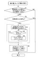
- FIG. 1 is a flowchart showing an operation state of an electromagnetic valve when raising the hydraulic pressure to a target hydraulic pressure, showing a first example of an embodiment of the present invention.
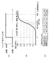
- 2 (A) and 2 (B) are diagrams for explaining a situation in which the hydraulic pressure in the hydraulic chamber increases when the electromagnetic valve is changed from fully closed to fully open.
- FIG. 2 (C) It is a map for obtaining target oil pressure.
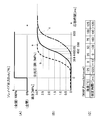
- FIGS. 3A and 3B are diagrams for explaining the influence of the oil temperature on the oil pressure increase, and FIG. 3C is a map for correcting this influence.
- FIG. 4 is a flowchart showing an operation state of the solenoid valve when the hydraulic pressure is lowered to the target hydraulic pressure, showing a second example of the embodiment of the present invention.
- FIG. 5 (A) and 5 (B) are diagrams for explaining a situation in which the hydraulic pressure in the hydraulic chamber drops when the electromagnetic valve is fully opened to fully closed, and FIG. It is a map for obtaining target oil pressure.
- 6 (A) and 6 (B) are diagrams for explaining the influence of the oil temperature on the hydraulic pressure drop, and FIG. 6 (C) is a map for correcting this influence.
- FIG. 7 is a block diagram showing an example of a conventional continuously variable transmission.
- FIG. 8 is a hydraulic circuit diagram of an example of a conventional continuously variable transmission.
- FIG. 9 is a diagram showing the relationship between the speed ratio of the toroidal continuously variable transmission and the speed ratio of the continuously variable transmission as a whole.
- the continuously variable transmission of this example is also basically similar to the conventional continuously variable transmission shown in FIGS. 7 and 8, the main shaft 3 as the input member, the toroidal continuously variable transmission 4, and the differential A planetary gear transmission 5 as a gear unit, an output shaft 9 as an output member, a clutch device 6, a control valve device 21, and a controller 16 are provided.
- the main shaft 3 is rotationally driven by the engine 1 via the damper 2.
- the toroidal continuously variable transmission 4 includes at least a pair of disks (an input disk 10 and an output disk 11), a plurality of power rollers 12, and a pressing device 14.
- the input disk 10 and the output disk 11 are composed of toroidal curved surfaces, respectively, have axial side surfaces facing each other, and are supported concentrically and relatively rotatable.
- Each of the power rollers 12 is rotatably supported by a support member (trunnion) that swings and displaces about a swing shaft that is twisted with respect to the center axes of the input disk 10 and the output disk 11.
- Each peripheral surface is in rolling contact with the axial side surface of the output disk 11.
- the pressing device 14 is hydraulic and presses the input disk 10 and the output disk 11 in a direction approaching each other, thereby rolling contact portions between the respective peripheral surfaces of the power roller 12 and the axial side surfaces of the input disk 10 and the output disk 11. Ensure sufficient surface pressure.
- the planetary gear transmission 5 is configured by combining a plurality of gears meshed with each other, and includes two input portions and one output portion, and a differential component of power input from these two input portions. Is output from the output unit.
- the output shaft 8 is rotationally driven by the output portion of the planetary gear transmission 5, and transmits the power of the output portion to the propeller shaft that is a driven member.
- the clutch device 6 changes the gear ratio between the main shaft 3 and the output shaft 9 by switching the power transmission state by the planetary gear transmission 5.
- the control valve device 21 adjusts the hydraulic pressure to be introduced into the hydraulic chamber of the clutch device 6 and the pressing force adjustment valve 27 for adjusting the hydraulic pressure introduced into the hydraulic chamber of the pressing device 14 and switches the connection state of the clutch device 6. And at least switching valves 23 and 24.
- the controller 16 controls the control valve device 21.
- the controller 16 has the input disk rotation sensor 29, the output disk rotation sensor 30, and the output shaft rotation sensor 31 to detect the respective rotation speeds of the input disk 10, the output disk 11, and the output shaft 9. Is input. Further, the controller 16 exchanges signals with the engine controller 32. Further, the controller 16 receives a shift mode switching signal indicating the connection / disconnection state of the low speed clutch 7 and the high speed clutch 8 and a T / M select position signal indicating the operation position of the select lever. In addition, a paddle shift signal for manual shifting, a foot brake signal indicating whether or not a brake pedal is operated, and an accelerator pedal opening signal indicating the amount of depression of the accelerator pedal are supplied to the controller 16 via the engine controller 32. Entered. In addition, a T / M oil temperature signal, which is detected by the T / M oil temperature sensor 33 and represents the oil temperature in the casing containing the continuously variable transmission, is also input to the controller.
- the feature of this example is that the hydraulic pressure in the hydraulic chamber is adjusted in order to reduce the time required for the hydraulic pressure in the hydraulic chamber provided in various hydraulic devices incorporated in the continuously variable transmission to reach a desired value (target hydraulic pressure).
- target hydraulic pressure a desired value
- the hydraulic pressure in the hydraulic chamber changes rapidly after a signal is sent to the solenoid valve.
- the configuration other than this characteristic part, including the basic configuration of the continuously variable transmission is the same as that of the conventional continuously variable transmission, the description thereof will be omitted or simplified, and the characteristic part of this example will be mainly described below.
- the pressing device 14 and the clutch device 6 shown in FIGS. 7 and 8 are configured as devices that rapidly change the hydraulic pressure in the hydraulic chamber in order to quickly reach the target hydraulic pressure in the hydraulic chamber. There are a low speed clutch 7 and a high speed clutch 8. Regardless of the part, the control procedure of the solenoid valve performed for rapidly changing the hydraulic pressure in the hydraulic chamber is the same.
- the solenoid valve adjusts the hydraulic pressure in the hydraulic chamber through which the hydraulic pressure introduction path provided with the solenoid valve passes by adjusting the opening degree determined according to the duty ratio.
- step 1 (S1) the controller 16 determines whether or not the current hydraulic pressure in the hydraulic chamber in which the hydraulic pressure is adjusted is substantially 0 [MPa]. Specifically, it is determined whether or not the duty ratio of the solenoid valve for introducing pressure oil into the hydraulic chamber is 0%, or whether or not the drive current of the solenoid valve is 0 [A]. It is judged by. When the current hydraulic pressure is not substantially zero (current hydraulic pressure> 0), the hydraulic pressure in the hydraulic chamber has risen to some extent, and a very rapid change in hydraulic pressure is not required to achieve the target hydraulic pressure. it is conceivable that. Therefore, in this case, the controller 16 ends the control of this example and performs normal hydraulic pressure control.
- step 2 the controller 16 sets the A value (for example, the target hydraulic pressure is a predetermined value) 1 [Mpa]) or more.
- the target hydraulic pressure is less than the value A (target hydraulic pressure ⁇ A)
- the controller 16 ends the control of this example and performs normal hydraulic pressure control.
- the process proceeds to the next step 3, and the controller 16 starts the timer at the same time as starting the control of this example.
- the duty ratio of the solenoid valve is set to 100%, which exceeds the value necessary and sufficient to maintain the target hydraulic pressure of 1 [MPa].
- the opening of the solenoid valve is fully open on the hydraulic pressure introduction side and fully closed on the hydraulic pressure discharge side.
- the rising characteristic of the hydraulic pressure shown in FIG. 2B is obtained in advance by simulation or the like, and is stored in the controller 16 (see FIG. 7) for controlling this electromagnetic valve.
- the controller 16 determines whether or not the predetermined time D has elapsed (Timer_T> D in step 4 (S4)). ).
- the predetermined time D is a time necessary and sufficient for the hydraulic pressure in the hydraulic chamber to reach 1 [Mpa], which is the target hydraulic pressure, and is obtained from the characteristics shown in FIG. 2 (B). Determined by the map.
- the hydraulic pressure in the hydraulic chamber is intended to be increased from 0 [Mpa] to 1 [Mpa], and the time required for this increase is 449 [msec]. Set to 449 [msec].
- step 4 the controller 16 determines whether or not the measurement time (Timer_T) of the timer started in step 3 has passed 449 [msec].
- step 5 the timer counter is incremented by 1, and the determination in step 4 is repeated.
- the controller 16 determines that the timer measurement time (Timer_T) is the predetermined time D (449 [msec] in Step 4. ]), It moves to step 6 (S6). Then, the controller 16 adjusts the duty ratio of the solenoid valve to 35% (output current 0.8 [A]), which is a necessary and sufficient value for maintaining the target hydraulic pressure of 1 [Mpa]. .
- the opening degree of the electromagnetic valve changes in the closing direction, the opening degree of the electromagnetic valve is returned to the desired opening degree, and the hydraulic pressure in the hydraulic chamber is maintained at 1 [Mpa] which is the target hydraulic pressure. Therefore, the control of this example by the controller 16 ends.
- the rise time required for the hydraulic pressure in the hydraulic chamber to rise varies depending on the viscosity of the hydraulic oil, which varies with temperature.
- the characteristics shown in FIG. 2 show the case where the temperature of the hydraulic oil is 25 ° C. However, when the temperature is high and the viscosity is low, the rise time is shortened, and conversely, the temperature is low and the viscosity is high. If this happens, this rise time will be longer.
- the hydraulic pressure in the hydraulic chamber is represented by a solid line a, a broken line b, and a chain line c.
- the duty ratio of the solenoid valve is set to 100% until the hydraulic pressure reaches the target hydraulic pressure, and the duty ratio of the solenoid valve needs to be adjusted to a value (35%) that can be maintained at the target hydraulic pressure at the moment when the target hydraulic pressure is reached. . Therefore, a correction map as shown in FIG. 3C is created in advance by simulation or the like, and this map is stored in the controller 16.
- the controller 16 sets the predetermined time D according to the temperature of the hydraulic oil. Allows you to adjust.
- the predetermined time E (449 [msec])
- the correction time F
- the predetermined time D is lengthened when the temperature is low, and the predetermined time D is shortened when the temperature is high.
- the pressing force control solenoid valve 19 which is a pressing force adjusting valve and the mode switching solenoid valve 20 (the low speed clutch control valve 23 and the high speed clutch control valve 24) which are switching valves.
- the pressure reducing valve 28 provided for adjusting the oil pressure in the oil supply line for supplying the pressure oil to the flow path provided with these valves is similarly an electromagnetic for adjusting the oil pressure in the oil supply line based on the duty ratio. A valve is preferred.
- the controller 16 changes the oil pressure in the oil supply line to a desired value exceeding a predetermined value, the opening degree of these solenoid valves changes most greatly corresponding to the direction of this change. After the adjustment, the opening degree of these solenoid valves is adjusted beyond the desired opening degree corresponding to the desired value, and then the opening degree of these solenoid valves is provided to the desired opening degree.
- FIG. 4 to 6 show a second example of the embodiment of the present invention.
- a case is shown in which the hydraulic pressure in the hydraulic pressure chamber where the current hydraulic pressure is the maximum value (3 [MPa]) in the adjustable range is lowered to 1 [Mpa] which is the target hydraulic pressure.
- Other conditions are the same as those in the first example of the embodiment, such as setting the duty ratio of the solenoid valve required to feed the hydraulic pressure of 1 [Mpa] into the hydraulic chamber to 35%.
- step 1 (S1) the controller 16 determines whether or not the current hydraulic pressure in the hydraulic chamber in which the hydraulic pressure is adjusted is the maximum hydraulic pressure. Specifically, this is because whether or not the duty ratio of the solenoid valve for introducing the pressure oil into the hydraulic chamber is 100% or the drive current of the solenoid valve is, for example, 2 [A ] Or not.
- the current hydraulic pressure is not the maximum hydraulic pressure (current hydraulic pressure ⁇ 3 [MPa])
- the hydraulic pressure in the hydraulic chamber has decreased to some extent, and in order to achieve the target hydraulic pressure of 1 [Mpa] It is thought that a very rapid change in hydraulic pressure is not required. Therefore, in this case, the controller 16 ends the control of this example and performs normal hydraulic pressure control.
- the current hydraulic pressure is substantially the highest hydraulic pressure (3 [MPa]) (current hydraulic pressure ⁇ 3 [MPa], and the duty ratio of the solenoid valve for introducing the pressure oil into the hydraulic chamber is approximately 100%.
- the process proceeds to step 2 (S2), and the controller 16 has a target hydraulic pressure equal to or less than an A value (for example, 1 [MPa]). It is determined whether or not.
- the target hydraulic pressure exceeds the predetermined value A (target hydraulic pressure> A)
- the controller 16 ends the control of this example and performs normal hydraulic pressure control.
- the controller 16 starts the timer at the same time as starting the control of this example.
- the controller 16 sets the duty ratio of the solenoid valve to 0%, fully closes the solenoid valve on the hydraulic pressure introduction side, and fully opens on the hydraulic pressure discharge side. To do.
- the hydraulic pressure in the hydraulic chamber, the hydraulic pressure of which is controlled by this electromagnetic valve drops as shown in FIG. This descent characteristic is also obtained in advance and stored in the controller 16 (see FIG. 7).
- step 4 it is determined whether or not the predetermined time D has elapsed. If it is determined that the predetermined time D (364 [msec]) has elapsed, the process proceeds to step 6. Then, the controller 16 adjusts the opening of the solenoid valve to 35% (output current 0.8 [A]), which is a necessary and sufficient value to maintain the target hydraulic pressure of 1 [Mpa]. To do. As a result, the hydraulic pressure in the hydraulic chamber is maintained at 1 [Mpa], which is the target hydraulic pressure, and the controller 16 ends the control of this example.
- the hydraulic pressure in the hydraulic chamber is set to the target hydraulic pressure (1 [Mpa]), regardless of the temperature change.
- This correction is performed based on a hydraulic pressure change characteristic and a map as shown in FIG. FIG. 6 is the same as FIG. 3 shown for the first example of the embodiment except that the direction of change in hydraulic pressure is opposite, and therefore redundant description is omitted.
- the present invention can be implemented in other patterns as long as it is necessary to rapidly change the hydraulic pressure in the hydraulic chamber to a certain level.
- the present invention can be implemented even when the intermediate value is increased from the intermediate value to the intermediate value, or conversely, the intermediate value is decreased from the intermediate value.
- the target hydraulic pressure is the highest value
- the duty ratio of the solenoid valve may be left at 100%
- the target hydraulic pressure is the lowest value
- the duty ratio may be left at 0%. Therefore, it is not necessary to carry out the present invention.
- the present invention is configured by combining a toroidal continuously variable transmission and a differential gear unit, and various hydraulic devices driven by hydraulic pressure such as a pressing device and a clutch, and for adjusting the hydraulic pressure in the hydraulic chamber of these hydraulic devices. And is widely applied to continuously variable transmissions that require high responsiveness of these hydraulic devices. Such continuously variable transmissions are widely used as automatic transmissions for vehicles including automobiles.
Landscapes
- Engineering & Computer Science (AREA)
- General Engineering & Computer Science (AREA)
- Mechanical Engineering (AREA)
- Physics & Mathematics (AREA)
- Fluid Mechanics (AREA)
- Control Of Transmission Device (AREA)
Description
図1~図3は、本発明の実施の形態の第1例を示している。本例の無段変速装置も、基本的には、図7および図8に示した従来の無段変速装置と同様に、入力部材である主軸3と、トロイダル無段変速機4と、差動歯車ユニットとしての遊星歯車変速機5と、出力部材である出力軸9と、クラッチ装置6と、制御弁装置21と、制御器16とを備える。主軸3は、ダンパ2を介してエンジン1により回転駆動される。トロイダル無段変速機4は、少なくとも1対のディスク(入力ディスク10および出力ディスク11)と、複数個のパワーローラ12と、押圧装置14とを備える。入力ディスク10および出力ディスク11は、トロイド曲面から構成され、互いに対向する軸方向側面をそれぞれ備え、互いに同心に、かつ、相対回転可能に支持されている。パワーローラ12のそれぞれは、入力ディスク10および出力ディスク11の中心軸に対し捩れの位置にある揺動軸を中心として揺動変位する支持部材(トラニオン)に回転可能に支持され、入力ディスク10および出力ディスク11の軸方向側面にそれぞれの周面を転がり接触させている。押圧装置14は、油圧式で、入力ディスク10および出力ディスク11を互いに近づく方向に押圧して、パワーローラ12のそれぞれの周面と入力ディスク10および出力ディスク11の軸方向側面との転がり接触部の面圧を確保する。遊星歯車変速機5は、互いに噛合した複数個の歯車を組み合わせて構成され、2箇所の入力部と1箇所の出力部とを備え、これら2箇所の入力部から入力される動力の差動分を前記出力部から出力する。出力軸8は、遊星歯車変速機5の出力部により回転駆動され、この出力部の動力を被駆動部材であるプロペラシャフトに伝達する。クラッチ装置6は、遊星歯車変速機5による動力の伝達状態を切り換えることにより、主軸3と出力軸9の間の変速比を変更する。制御弁装置21は、押圧装置14の油圧室内に導入する油圧を調節するための押圧力調整弁27と、クラッチ装置6の油圧室内に導入する油圧を調節し、クラッチ装置6の接続状態を切り換えるための切換弁23、24とを少なくとも備える。
図4~図6は、本発明の実施の形態の第2例を示している。本例の場合には、現在油圧が調節可能範囲の最高値(3[MPa])である油圧室内の油圧を、目標油圧である1[Mpa]にまで降下させる場合を示す。この油圧室に1[Mpa]なる油圧を送り込むために必要とされる電磁弁のデューティ比を35%とするなど、その他の条件は、実施の形態の第1例の場合と同じである。
2 ダンパ
3 主軸
4 トロイダル無段変速機
5 遊星歯車変速機
6 クラッチ装置
7 低速用クラッチ
8 高速用クラッチ
9 出力軸
10 入力ディスク
11 出力ディスク
12 パワーローラ
13 アクチュエータ
14 押圧装置
15 変速比制御ユニット
16 制御器(ECU)
17 ステッピングモータ
18 ライン圧制御用電磁弁
19 押圧力制御用電磁弁
20 モード切換用電磁弁
21 制御弁装置
22 変速比制御弁
23 低速クラッチ用切換弁
24 高速クラッチ用切換弁
25 給油ポンプ
26 油溜
27 押圧力調整弁
28 減圧弁
29 入力ディスク回転センサ
30 出力ディスク回転センサ
31 出力軸回転センサ
32 エンジン制御器
33 T/M油温センサ
Claims (6)
- エンジンまたは電動モータにより回転駆動される入力部材と、
トロイド曲面から構成され、互いに対向する軸方向側面をそれぞれ備え、互いに同心に、かつ、相対回転可能に支持された、少なくとも1対のディスクと、該1対のディスクの中心軸に対し捩れの位置にある揺動軸を中心として揺動変位する支持部材に回転可能にそれぞれ支持され、前記1対のディスクの軸方向側面にそれぞれの周面を転がり接触させた、複数個のパワーローラと、前記1対のディスクを互いに近づく方向に押圧して、前記複数個のパワーローラのそれぞれの周面と前記1対のディスクの軸方向側面との転がり接触部の面圧を確保する、油圧式の押圧装置と、を備えるトロイダル無段変速機と、
互いに噛合した複数個の歯車を組み合わせて構成され、2箇所の入力部と1箇所の出力部とを備え、前記入力部から入力される動力の差動分を前記出力部から出力する差動歯車ユニットと、
前記差動歯車ユニットの前記出力部により回転駆動されて、該出力部の動力を被駆動部材に伝達する出力部材と、
前記差動歯車ユニットによる動力の伝達状態を切り換えることにより、前記入力部材と前記出力部材との間の変速比を変更するクラッチ装置と、
前記押圧装置の油圧室内に導入する油圧を調節するための押圧力調整弁と、前記クラッチ装置の油圧室内に導入する油圧を調節し、該クラッチ装置の接続状態を切り換えるための切換弁とを備える制御弁装置と、
前記制御弁装置を制御するための制御器と、
を備え、
前記押圧力調整弁と前記切換弁とのうちの少なくとも一方の弁は、単位時間当たりにソレノイドに通電している時間の割合であるデューティ比に応じて定まる開度を調節することにより、該少なくとも一方の弁を設けた油圧導入路が通じる前記油圧室内の油圧を調節する電磁弁であり、
前記制御器は、前記電磁弁の開度が、前記油圧室内の油圧を所望値に調節できる所望開度にまで、所定値を超えて変化する場合に、該変化の方向に対応し、前記電磁弁の開度が最も大きく変化した状態にまで、該電磁弁の開度を、前記所望開度を超えて調節した後、所定時間後に、該電磁弁の開度を前記所望開度に戻す機能を有する、
無段変速装置。 - 前記押圧力調整弁と前記切換弁の両方が、前記電磁弁により構成される、請求項1に記載の無段変速装置。
- 前記制御器は、前記油圧室内の油圧を、前記所定値を超えて上昇させる際に、前記電磁弁を全開状態とした後、前記所定時間後に、該電磁弁の開度を閉鎖方向に変化させて、該電磁弁の開度を前記所望開度とする、請求項1に記載の無段変速装置。
- 前記制御器は、前記油圧室内の油圧を、前記所定値を超えて降下させる際に、前記電磁弁を全閉状態とした後、前記所定時間後に、該電磁弁の開度を開放方向に変化させて、該電磁弁の開度を前記所望開度とする、請求項1に記載の無段変速装置。
- 前記制御器は、前記油圧室に導入される作動油の温度に応じて、前記所定時間を補正する機能を有する、請求項1に記載の無段変速装置。
- 前記押圧力調整弁および前記切換弁を設けた流路に圧油を供給する給油ライン中の油圧を調節するための減圧弁を備え、該減圧弁をデューティ比に基づいて該給油ライン中の油圧を調節する電磁弁とし、前記制御器は、該給油ライン中の油圧を、所定値を超えて所望値にまで変化させる際に、該変化の方向に対応し、前記電磁弁の開度が最も大きく変化した状態にまで、該電磁弁の開度を、前記所望値に対応する所望開度を超えて調節した後、該電磁弁の開度を前記所望開度に戻す機能を有する、請求項1に記載の無段変速装置。
Priority Applications (5)
| Application Number | Priority Date | Filing Date | Title |
|---|---|---|---|
| CA2886366A CA2886366A1 (en) | 2012-09-26 | 2013-09-12 | Continuously variable transmission device |
| CN201380050183.1A CN105026799B (zh) | 2012-09-26 | 2013-09-12 | 无级变速装置 |
| US14/431,344 US9534686B2 (en) | 2012-09-26 | 2013-09-12 | Continuously variable transmission device |
| DE112013004712.8T DE112013004712T5 (de) | 2012-09-26 | 2013-09-12 | Kontinuierlich variable Getriebevorrichtung |
| JP2014538385A JP5898777B2 (ja) | 2012-09-26 | 2013-09-12 | 無段変速装置 |
Applications Claiming Priority (2)
| Application Number | Priority Date | Filing Date | Title |
|---|---|---|---|
| JP2012211755 | 2012-09-26 | ||
| JP2012-211755 | 2012-09-26 |
Publications (1)
| Publication Number | Publication Date |
|---|---|
| WO2014050593A1 true WO2014050593A1 (ja) | 2014-04-03 |
Family
ID=50388000
Family Applications (1)
| Application Number | Title | Priority Date | Filing Date |
|---|---|---|---|
| PCT/JP2013/074711 Ceased WO2014050593A1 (ja) | 2012-09-26 | 2013-09-12 | 無段変速装置 |
Country Status (6)
| Country | Link |
|---|---|
| US (1) | US9534686B2 (ja) |
| JP (1) | JP5898777B2 (ja) |
| CN (1) | CN105026799B (ja) |
| CA (1) | CA2886366A1 (ja) |
| DE (1) | DE112013004712T5 (ja) |
| WO (1) | WO2014050593A1 (ja) |
Families Citing this family (1)
| Publication number | Priority date | Publication date | Assignee | Title |
|---|---|---|---|---|
| US10316968B2 (en) * | 2017-05-16 | 2019-06-11 | GM Global Technology Operations LLC | Method and apparatus for ratio control for a continuously variable transmission |
Citations (1)
| Publication number | Priority date | Publication date | Assignee | Title |
|---|---|---|---|---|
| JP2000193076A (ja) * | 1998-12-28 | 2000-07-14 | Mazda Motor Corp | パワ―トレインの制御装置 |
Family Cites Families (13)
| Publication number | Priority date | Publication date | Assignee | Title |
|---|---|---|---|---|
| JP3760545B2 (ja) * | 1996-03-29 | 2006-03-29 | マツダ株式会社 | 自動変速機の制御装置 |
| JP3711688B2 (ja) * | 1997-03-22 | 2005-11-02 | マツダ株式会社 | トロイダル式無段変速機 |
| JP4085457B2 (ja) | 1998-02-23 | 2008-05-14 | 日本精工株式会社 | 無段変速装置 |
| JP3680746B2 (ja) * | 2001-03-09 | 2005-08-10 | 日産自動車株式会社 | 変速比無限大無段変速機の制御装置 |
| JP4599905B2 (ja) | 2003-06-26 | 2010-12-15 | 日本精工株式会社 | 無段変速装置 |
| JP4151500B2 (ja) * | 2003-07-18 | 2008-09-17 | トヨタ自動車株式会社 | 油流制御弁の対向接続による油圧制御装置 |
| JP5176496B2 (ja) * | 2007-11-13 | 2013-04-03 | 日本精工株式会社 | トロイダル型無段変速機 |
| JP4363486B2 (ja) * | 2008-01-22 | 2009-11-11 | トヨタ自動車株式会社 | 無段変速機の制御装置および制御方法 |
| JP4941350B2 (ja) | 2008-02-21 | 2012-05-30 | 日本精工株式会社 | 無段変速装置 |
| JP4605245B2 (ja) * | 2008-04-24 | 2011-01-05 | トヨタ自動車株式会社 | 油圧制御装置 |
| JP4539765B2 (ja) * | 2008-08-08 | 2010-09-08 | トヨタ自動車株式会社 | トロイダル式無段変速機 |
| JP5310597B2 (ja) * | 2010-02-23 | 2013-10-09 | 日本精工株式会社 | 無段変速装置 |
| JP5471876B2 (ja) | 2010-06-21 | 2014-04-16 | 日本精工株式会社 | 無段変速装置 |
-
2013
- 2013-09-12 WO PCT/JP2013/074711 patent/WO2014050593A1/ja not_active Ceased
- 2013-09-12 DE DE112013004712.8T patent/DE112013004712T5/de not_active Withdrawn
- 2013-09-12 JP JP2014538385A patent/JP5898777B2/ja not_active Expired - Fee Related
- 2013-09-12 CA CA2886366A patent/CA2886366A1/en not_active Abandoned
- 2013-09-12 CN CN201380050183.1A patent/CN105026799B/zh not_active Expired - Fee Related
- 2013-09-12 US US14/431,344 patent/US9534686B2/en not_active Expired - Fee Related
Patent Citations (1)
| Publication number | Priority date | Publication date | Assignee | Title |
|---|---|---|---|---|
| JP2000193076A (ja) * | 1998-12-28 | 2000-07-14 | Mazda Motor Corp | パワ―トレインの制御装置 |
Also Published As
| Publication number | Publication date |
|---|---|
| CN105026799A (zh) | 2015-11-04 |
| CA2886366A1 (en) | 2014-04-03 |
| US9534686B2 (en) | 2017-01-03 |
| JPWO2014050593A1 (ja) | 2016-08-22 |
| US20160131254A1 (en) | 2016-05-12 |
| JP5898777B2 (ja) | 2016-04-06 |
| DE112013004712T5 (de) | 2015-06-11 |
| CN105026799B (zh) | 2016-11-09 |
Similar Documents
| Publication | Publication Date | Title |
|---|---|---|
| US20010041640A1 (en) | Infinite speed ratio continuously variable transmission | |
| JP5463425B2 (ja) | 車両用無段変速装置 | |
| JP5287762B2 (ja) | 無段変速装置 | |
| JP5898777B2 (ja) | 無段変速装置 | |
| JP4710360B2 (ja) | トロイダル型無段変速機及び無段変速装置 | |
| JP5176496B2 (ja) | トロイダル型無段変速機 | |
| JP5659088B2 (ja) | 車両用無段変速装置 | |
| JP5262995B2 (ja) | 車両用無段変速装置 | |
| JP4924449B2 (ja) | 無段変速装置 | |
| JP4670569B2 (ja) | 無段変速装置 | |
| JP5682359B2 (ja) | トロイダル型無段変速機及び無段変速装置 | |
| JP4700275B2 (ja) | 無段変速機の制御装置 | |
| JP6631067B2 (ja) | 無段変速装置 | |
| JP4853264B2 (ja) | 無段変速装置 | |
| JP2002013621A (ja) | パワートレインの制御装置 | |
| JP2005172010A (ja) | 無段変速機の制御装置 | |
| JP5732847B2 (ja) | トロイダル型無段変速機及び無段変速装置 | |
| JP4534726B2 (ja) | トロイダル型無段変速機及び無段変速装置 | |
| JP4590984B2 (ja) | 燃料供給装置 | |
| JP5447609B2 (ja) | トロイダル型無段変速機及び無段変速装置 | |
| JP4941328B2 (ja) | 無段変速装置 | |
| JP2017008992A (ja) | トロイダル型無段変速機 | |
| JP2013002566A (ja) | 車両用無段変速装置 | |
| JP2007239843A (ja) | 車両用無段変速機の変速比制御装置 | |
| JP2014152794A (ja) | トロイダル型無段変速機 |
Legal Events
| Date | Code | Title | Description |
|---|---|---|---|
| WWE | Wipo information: entry into national phase |
Ref document number: 201380050183.1 Country of ref document: CN |
|
| 121 | Ep: the epo has been informed by wipo that ep was designated in this application |
Ref document number: 13840445 Country of ref document: EP Kind code of ref document: A1 |
|
| ENP | Entry into the national phase |
Ref document number: 2014538385 Country of ref document: JP Kind code of ref document: A |
|
| ENP | Entry into the national phase |
Ref document number: 2886366 Country of ref document: CA |
|
| WWE | Wipo information: entry into national phase |
Ref document number: 112013004712 Country of ref document: DE Ref document number: 1120130047128 Country of ref document: DE |
|
| 122 | Ep: pct application non-entry in european phase |
Ref document number: 13840445 Country of ref document: EP Kind code of ref document: A1 |
|
| WWE | Wipo information: entry into national phase |
Ref document number: 14431344 Country of ref document: US |