WO2014046040A1 - スパッタリングターゲット - Google Patents
スパッタリングターゲット Download PDFInfo
- Publication number
- WO2014046040A1 WO2014046040A1 PCT/JP2013/074840 JP2013074840W WO2014046040A1 WO 2014046040 A1 WO2014046040 A1 WO 2014046040A1 JP 2013074840 W JP2013074840 W JP 2013074840W WO 2014046040 A1 WO2014046040 A1 WO 2014046040A1
- Authority
- WO
- WIPO (PCT)
- Prior art keywords
- powder
- target
- mol
- sputtering
- sputtering target
- Prior art date
- Legal status (The legal status is an assumption and is not a legal conclusion. Google has not performed a legal analysis and makes no representation as to the accuracy of the status listed.)
- Ceased
Links
Classifications
-
- H—ELECTRICITY
- H01—ELECTRIC ELEMENTS
- H01J—ELECTRIC DISCHARGE TUBES OR DISCHARGE LAMPS
- H01J37/00—Discharge tubes with provision for introducing objects or material to be exposed to the discharge, e.g. for the purpose of examination or processing thereof
- H01J37/32—Gas-filled discharge tubes
- H01J37/34—Gas-filled discharge tubes operating with cathodic sputtering
- H01J37/3411—Constructional aspects of the reactor
- H01J37/3414—Targets
- H01J37/3426—Material
- H01J37/3429—Plural materials
-
- C—CHEMISTRY; METALLURGY
- C23—COATING METALLIC MATERIAL; COATING MATERIAL WITH METALLIC MATERIAL; CHEMICAL SURFACE TREATMENT; DIFFUSION TREATMENT OF METALLIC MATERIAL; COATING BY VACUUM EVAPORATION, BY SPUTTERING, BY ION IMPLANTATION OR BY CHEMICAL VAPOUR DEPOSITION, IN GENERAL; INHIBITING CORROSION OF METALLIC MATERIAL OR INCRUSTATION IN GENERAL
- C23C—COATING METALLIC MATERIAL; COATING MATERIAL WITH METALLIC MATERIAL; SURFACE TREATMENT OF METALLIC MATERIAL BY DIFFUSION INTO THE SURFACE, BY CHEMICAL CONVERSION OR SUBSTITUTION; COATING BY VACUUM EVAPORATION, BY SPUTTERING, BY ION IMPLANTATION OR BY CHEMICAL VAPOUR DEPOSITION, IN GENERAL
- C23C14/00—Coating by vacuum evaporation, by sputtering or by ion implantation of the coating forming material
- C23C14/06—Coating by vacuum evaporation, by sputtering or by ion implantation of the coating forming material characterised by the coating material
- C23C14/08—Oxides
-
- C—CHEMISTRY; METALLURGY
- C23—COATING METALLIC MATERIAL; COATING MATERIAL WITH METALLIC MATERIAL; CHEMICAL SURFACE TREATMENT; DIFFUSION TREATMENT OF METALLIC MATERIAL; COATING BY VACUUM EVAPORATION, BY SPUTTERING, BY ION IMPLANTATION OR BY CHEMICAL VAPOUR DEPOSITION, IN GENERAL; INHIBITING CORROSION OF METALLIC MATERIAL OR INCRUSTATION IN GENERAL
- C23C—COATING METALLIC MATERIAL; COATING MATERIAL WITH METALLIC MATERIAL; SURFACE TREATMENT OF METALLIC MATERIAL BY DIFFUSION INTO THE SURFACE, BY CHEMICAL CONVERSION OR SUBSTITUTION; COATING BY VACUUM EVAPORATION, BY SPUTTERING, BY ION IMPLANTATION OR BY CHEMICAL VAPOUR DEPOSITION, IN GENERAL
- C23C14/00—Coating by vacuum evaporation, by sputtering or by ion implantation of the coating forming material
- C23C14/06—Coating by vacuum evaporation, by sputtering or by ion implantation of the coating forming material characterised by the coating material
- C23C14/14—Metallic material, boron or silicon
-
- C—CHEMISTRY; METALLURGY
- C23—COATING METALLIC MATERIAL; COATING MATERIAL WITH METALLIC MATERIAL; CHEMICAL SURFACE TREATMENT; DIFFUSION TREATMENT OF METALLIC MATERIAL; COATING BY VACUUM EVAPORATION, BY SPUTTERING, BY ION IMPLANTATION OR BY CHEMICAL VAPOUR DEPOSITION, IN GENERAL; INHIBITING CORROSION OF METALLIC MATERIAL OR INCRUSTATION IN GENERAL
- C23C—COATING METALLIC MATERIAL; COATING MATERIAL WITH METALLIC MATERIAL; SURFACE TREATMENT OF METALLIC MATERIAL BY DIFFUSION INTO THE SURFACE, BY CHEMICAL CONVERSION OR SUBSTITUTION; COATING BY VACUUM EVAPORATION, BY SPUTTERING, BY ION IMPLANTATION OR BY CHEMICAL VAPOUR DEPOSITION, IN GENERAL
- C23C14/00—Coating by vacuum evaporation, by sputtering or by ion implantation of the coating forming material
- C23C14/22—Coating by vacuum evaporation, by sputtering or by ion implantation of the coating forming material characterised by the process of coating
- C23C14/34—Sputtering
- C23C14/3407—Cathode assembly for sputtering apparatus, e.g. Target
- C23C14/3414—Metallurgical or chemical aspects of target preparation, e.g. casting, powder metallurgy
-
- G—PHYSICS
- G11—INFORMATION STORAGE
- G11B—INFORMATION STORAGE BASED ON RELATIVE MOVEMENT BETWEEN RECORD CARRIER AND TRANSDUCER
- G11B5/00—Recording by magnetisation or demagnetisation of a record carrier; Reproducing by magnetic means; Record carriers therefor
- G11B5/84—Processes or apparatus specially adapted for manufacturing record carriers
- G11B5/851—Coating a support with a magnetic layer by sputtering
-
- H—ELECTRICITY
- H01—ELECTRIC ELEMENTS
- H01J—ELECTRIC DISCHARGE TUBES OR DISCHARGE LAMPS
- H01J37/00—Discharge tubes with provision for introducing objects or material to be exposed to the discharge, e.g. for the purpose of examination or processing thereof
- H01J37/32—Gas-filled discharge tubes
- H01J37/34—Gas-filled discharge tubes operating with cathodic sputtering
- H01J37/3411—Constructional aspects of the reactor
- H01J37/3414—Targets
- H01J37/3426—Material
-
- H—ELECTRICITY
- H01—ELECTRIC ELEMENTS
- H01J—ELECTRIC DISCHARGE TUBES OR DISCHARGE LAMPS
- H01J2237/00—Discharge tubes exposing object to beam, e.g. for analysis treatment, etching, imaging
- H01J2237/32—Processing objects by plasma generation
- H01J2237/33—Processing objects by plasma generation characterised by the type of processing
- H01J2237/332—Coating
Definitions
- the present invention relates to a sputtering target used for forming a magnetic thin film of a magnetic recording medium, in particular, a magnetic recording layer of a hard disk adopting a perpendicular magnetic recording method, and has a small initial particle, and a stable discharge can be obtained during sputtering.
- the present invention relates to a non-magnetic material particle-dispersed sputtering target.
- a material based on Co, Fe, or Ni which is a ferromagnetic metal, is used as a magnetic thin film material for recording.
- a Co—Cr-based or Co—Cr—Pt-based ferromagnetic alloy containing Co as a main component has been used for a recording layer of a hard disk employing an in-plane magnetic recording method.
- a recording layer of a hard disk employing a perpendicular magnetic recording method includes a composite made of a Co—Cr-based or Co—Cr—Pt-based ferromagnetic alloy containing Co as a main component and a nonmagnetic inorganic substance. Many materials are used.
- a magnetic thin film of a magnetic recording medium such as a hard disk is often produced by sputtering a ferromagnetic material sputtering target containing the above material as a component because of its high productivity.
- a melting method or a powder metallurgy method can be considered as a method for producing such a ferromagnetic material sputtering target. Which method is used depends on the required characteristics, so it cannot be generally stated, but the sputtering target made of a ferromagnetic alloy and non-magnetic inorganic particles used for the recording layer of a perpendicular magnetic recording hard disk is Generally, it is produced by a powder metallurgy method. This is because the inorganic particles need to be uniformly dispersed in the alloy substrate, and thus it is difficult to produce by the melting method.
- Patent Document 1 a mixed powder obtained by mixing Co powder, Cr powder, TiO 2 powder and SiO 2 powder and Co spherical powder are mixed with a planetary motion mixer, and this mixed powder is molded by hot pressing and used for a magnetic recording medium.
- Patent Document 1 A method for obtaining a sputtering target has been proposed (Patent Document 1).
- the target structure in this case has a spherical metal phase (B) having a higher magnetic permeability than the surrounding structure in the phase (A) which is a metal substrate in which inorganic particles are dispersed (Patent Document). 1 of FIG.
- Such a structure is excellent in terms of improving the leakage magnetic flux, but it can be said that there is a slight problem in terms of suppressing the generation of particles during sputtering.
- Patent Document 2 discloses that the surface roughness Ra ⁇ 1.0 ⁇ m of the sputtering target, refractory metal elements other than the main components and alloy components that are contaminants, and Si, Al, Co, Ni, B
- a sputtering target having a total amount of 500 ppm or less, a surface hydrogen content of 50 ppm or less, and a thickness of a work-affected layer of 50 ⁇ m or less, and a technique for producing the target by precision cutting using a diamond bite if necessary is disclosed.
- a technique is disclosed in which the thickness of a film formed on a substrate by sputtering is made uniform, and the generation of particles is suppressed by suppressing the generation of nodules during sputtering.
- surface processing is easy, and the effect of suppressing particles is relatively easy.
- Patent Document 3 discloses a sputtering target for a magnetic recording film, which is a sputtering target composed of a matrix phase containing Co and Pt and a metal oxide phase, having a magnetic permeability of 6 to 15 and a relative density of 90% or more. Further, when the surface of the sputtering target is observed with a scanning analytical electron microscope, the average particle diameter of the particles formed by the matrix phase and the average particle diameter of the particles formed by the metal oxide phase are both 0.05 ⁇ m.
- the above-mentioned sputtering target for a magnetic recording film which is less than 7.0 ⁇ m and the average particle size of the particles formed by the matrix phase is larger than the average particle size of the particles formed by the metal oxide phase.
- the above-mentioned sputtering target for a magnetic recording film is disclosed in which the X-ray diffraction peak intensity ratio represented by the formula (I) is 0.7 to 1.0 in X-ray diffraction analysis.
- the X-ray diffraction peak intensity ratio represented by the formula (I) is the X-ray diffraction peak intensity of the [002] plane of Co ((X-ray diffraction peak intensity of [103] plane + [002] plane). It shows the ratio divided by (X-ray diffraction peak intensity) and cannot be used in the invention contemplated by the present invention.
- Patent Document 4 discloses a method of treating a surface of a sputtering target that removes the surface deformation layer and shortens the burn-in time during sputtering, and the target surface is brought into contact with a viscoelastic polishing medium (VEAM).
- VEAM viscoelastic polishing medium
- oxide phase is exposed to the target surface is damaged, such as by machining, chipping and pluck
- the generation of particles increases during sputtering, and even if the chipping or flaking of the oxide phase caused by this machining can be solved, residual strain due to surface processing exists in the target. Caused the generation of particles.
- the residual processing strain is not sufficiently grasped, the surface processing method and processing accuracy are affected, and the fundamental solution of particle generation has not been achieved.
- the present inventors have conducted intensive research. As a result, the residual processing strain of the sputtering target is reduced, the residual processing strain of the target is investigated by XRD, and the XRD has a single peak. By making the integration width of the highest peak below a certain limit, it is possible to greatly reduce the burn-in time by suppressing the generation of initial particles during sputtering, and obtain a stable discharge during sputtering. It has been found that a non-magnetic material particle-dispersed sputtering target can be provided.
- a sputtering target composed of a metal matrix phase containing Co and a 6 to 25 mol% oxide phase (hereinafter referred to as an “oxide phase”) that is dispersed in the form of particles.
- the sputtering target is characterized in that the integral width of the highest peak among the single peaks of XRD is 0.7 or less.
- the present invention also provides: 2) The sputtering target according to 1) above, wherein the metal matrix phase is Cr in an amount of 5 mol% to 40 mol%, and the remainder is Co and inevitable impurities.
- the present invention provides 3) The sputtering target according to 1) above, wherein the metal matrix phase is Cr 5 mol% to 40 mol%, Pt 5 mol% to 30 mol%, and the remainder is Co and inevitable impurities. .
- the oxide phase is one or more selected from SiO 2 , TiO 2 , Ti 2 O 3 , Cr 2 O 3 , Ta 2 O 5 , Ti 5 O 9 , B 2 O 3 , CoO, Co 3 O 4 .
- the present invention provides 5) The above 1 characterized in that the metal matrix phase contains 0.5 mol% to 10 mol% of one or more elements selected from B, Ti, V, Mn, Zr, Nb, Ru, Mo, Ta, and W.
- the sputtering target according to any one of 4) to 4) is provided.
- the present invention provides a non-magnetic material particle-dispersed sputtering target that can significantly reduce the burn-in time by suppressing the generation of initial particles during sputtering and can obtain a stable discharge during sputtering. be able to. This also increases the target life and makes it possible to manufacture a magnetic thin film at low cost. Furthermore, it has the effect of significantly improving the quality of the film formed by sputtering.
- the components constituting the sputtering target of the present invention are a metal matrix phase containing Co, and a 6 to 25 mol% oxide phase (hereinafter referred to as “oxide phase”) present in a dispersed form.
- Consists of The integral width of the highest peak among the single peaks of XRD is 0.7 or less. This is an index for reducing the residual processing strain. As a result, the residual processing strain can be reduced, so that the generation of initial particles due to the residual processing strain is small, and the burn-in time can be greatly reduced.
- sputtering targets are ferromagnetic material sputtering targets used for forming a magnetic thin film of a magnetic recording medium, particularly a magnetic recording layer of a hard disk adopting a perpendicular magnetic recording method.
- the oxide phase may be one or more selected from SiO 2 , TiO 2 , Ti 2 O 3 , Cr 2 O 3 , Ta 2 O 5 , Ti 5 O 9 , B 2 O 3 , CoO, and Co 3 O 4 .
- the target of the present invention contains 5 to 25 mol% of these. In the examples to be described later, some of these are shown, but all have almost equivalent functions as oxides.
- the sputtering target of the present invention contains 0.5 mol% to 10 mol% of one or more elements selected from B, Ti, V, Mn, Zr, Nb, Ru, Mo, Ta, and W as the metal matrix phase. be able to. These are elements added as necessary in order to improve the characteristics as a magnetic recording medium.
- the mixing ratio can be developed within the above range, but any of them can maintain the characteristics as an effective magnetic recording medium.
- the ferromagnetic material sputtering target of the present invention is produced by powder metallurgy.
- a powder of each metal element and, if necessary, a powder of an additive metal element are prepared. These powders desirably have a maximum particle size of 20 ⁇ m or less. Further, alloy powders of these metals may be prepared instead of the powders of the respective metal elements, but in this case as well, it is desirable that the maximum particle size is 20 ⁇ m or less.
- these metal powders are weighed so as to have a desired composition, and mixed using a known method such as a ball mill for pulverization. What is necessary is just to mix with a metal powder at this stage, when adding an inorganic substance powder.
- An oxide powder is prepared as the inorganic powder, and it is desirable to use an oxide powder having a maximum particle size of 5 ⁇ m or less.
- Co Co coarse particles or Co atomized powder is used as a part of Co raw material. At this time, the mixing ratio of Co coarse particles or Co atomized powder is adjusted so that the oxide does not exceed 25 mol%.
- a Co atomized powder having a diameter in the range of 50 to 150 ⁇ m is prepared, and the Co atomized powder and the above mixed powder are pulverized and mixed using an attritor.
- the mixing device a ball mill, a mortar, or the like can be used, but it is desirable to use a powerful mixing method such as a ball mill.
- the prepared Co atomized powder can be individually pulverized to produce Co coarse powder having a diameter in the range of 50 to 300 ⁇ m and mixed with the above mixed powder.
- a mixing apparatus a ball mill, a Newgra machine (stirrer), a mixer, a mortar, etc. are preferable.
- the powder obtained in this manner is molded and sintered using a vacuum hot press apparatus and cut into a desired shape, thereby producing the ferromagnetic sputtering target of the present invention.
- the molding / sintering is not limited to hot pressing, and a plasma discharge sintering method and a hot isostatic pressing method can also be used.
- the holding temperature at the time of sintering is preferably set to the lowest temperature in a temperature range where the target is sufficiently densified. Depending on the composition of the target, it is often in the temperature range of 800-1200 ° C. This is because crystal growth of the sintered body can be suppressed by keeping the sintering temperature low.
- the pressure during sintering is preferably 300 to 500 kg / cm 2 .
- Example 1 As raw material powder, Co powder having an average particle diameter of 3 ⁇ m, Cr powder having an average particle diameter of 5 ⁇ m, Pt powder having an average particle diameter of 1 ⁇ m, SiO 2 powder having an average particle diameter of 1 ⁇ m, Co coarse powder having a diameter in the range of 50 to 300 ⁇ m. Prepared. Co powder, Cr powder, Pt powder, SiO 2 powder, and Co coarse powder were weighed so that these powders had a target composition of 62Co-15Cr-15Pt-8SiO 2 (mol%).
- Co powder, Cr powder, Pt powder, and SiO 2 powder were sealed in a ball mill pot with a capacity of 10 liters together with zirconia balls as a grinding medium, and rotated and mixed for 20 hours. Further, the obtained mixed powder and Co coarse powder were put into an attritor, and pulverized and mixed.
- This mixed powder was filled into a carbon mold and hot-pressed in a vacuum atmosphere under the conditions of a temperature of 1100 ° C, a holding time of 2 hours, and a pressure of 30 MPa to obtain a sintered body. Further, this was cut with a lathe and then subjected to rotary surface grinding to obtain a disk-shaped target having a diameter of 180 mm and a thickness of 5 mm. The finishing amount was 50 ⁇ m. Table 1 shows these processes, finishing methods, and finishing amounts.
- Example 1 In the same manner as in Example 1, a target material having a composition of 62Co-15Cr-15Pt-8SiO 2 (mol%) was produced. However, the machining method was prepared by lathe finishing after surface grinding. The finishing amount was 25 ⁇ m. When XRD measurement was performed to estimate the residual strain remaining on the target surface, the integration width of the maximum 50 ° peak among the single peaks was 1.2, exceeding the range of the present invention. It was. The results of sputtering this target are shown in Table 1. Even after 2.5 kWh sputtering, the number of particles did not decrease below the background level (5).
- Example 2 A target material having the same composition as that of Example 1 was produced by polishing after lathe machining. The finishing amount was 1 ⁇ m.
- XRD measurement was performed to estimate the residual strain remaining on the target surface, the integration width of the maximum 50 ° peak among the single peaks was 0.8, exceeding the range of the present invention. It was.
- the results of sputtering this target are shown in Table 1. At the time of 1.4 kWh sputtering, the number of particles decreased below the background level (5), but the burn-in time was longer than that in Example 1.
- Example 3 A target material having the same composition as that of Example 1 was prepared by polishing after lathe processing and surface grinding after lathe processing.
- the finishing amount was 25 ⁇ m (surface grinding) +1 ⁇ m (polishing).
- the integration width of the maximum 50 ° peak among the single peaks was 0.8, which exceeded the scope of the present invention.
- the number of particles decreased to the background level (5) or less when 1.3 kWh was sputtered, but the burn-in time was longer than that in Example 1.
- Example 2 As raw material powder, Co powder having an average particle diameter of 3 ⁇ m, Cr powder having an average particle diameter of 5 ⁇ m, Pt powder having an average particle diameter of 1 ⁇ m, TiO 2 powder having an average particle diameter of 1 ⁇ m, Co coarse powder having a diameter in the range of 50 to 300 ⁇ m. Prepared. Co powder, Cr powder, Pt powder, TiO 2 powder, CoO powder, and Co coarse powder were weighed so that these powders had a target composition of 54Co-20Cr-15Pt-5TiO 2 -6CoO (mol%). Thereafter, a target material was produced in the same manner as in Example 1.
- the machining method was prepared by cutting 50 ⁇ m by surface grinding after lathe processing.
- the finishing amount was 50 ⁇ m.
- the integral width of the 50 ° peak which is the maximum among the single peaks, was 0.7.
- the number of particles decreased to a background level (5) or less when 0.8 kWh was sputtered, and good results were obtained.
- Table 1 The above results are similarly shown in Table 1.
- Example 4 A target material having the same composition as that of Example 2 was manufactured by laminating 25 ⁇ m by surface grinding after lathe machining. As a result of the XRD measurement, the integral width of the 50 ° peak, which is the maximum among the single peaks, was 1.1, exceeding the range of the present invention. As a result of sputtering this target, the number of particles decreased to a background level (five) or less when 2.3 kWh was sputtered, but the burn-in time was longer than that in Example 2. The above results are similarly shown in Table 1.
- Example 3 As raw material powder, Co powder with an average particle diameter of 3 ⁇ m, Cr powder with an average particle diameter of 5 ⁇ m, Pt powder with an average particle diameter of 1 ⁇ m, TiO 2 powder with an average particle diameter of 1 ⁇ m, SiO 2 powder with an average particle diameter of 1 ⁇ m, and an average particle diameter of 1 ⁇ m Cr 2 O 3 powder, Co coarse powder having a diameter in the range of 50 to 300 ⁇ m was prepared. Co powder, Cr powder, Pt powder, TiO 2 powder, SiO 2 powder, so that these powders have a target composition of 61Co-15Cr-15Pt-3TiO 2 -3SiO 2 -3Cr 2 O 3 (mol%), Cr 2 O 3 powder and Co coarse powder were weighed. Thereafter, a target material was produced in the same manner as in Example 1.
- the machining method was a lathe, followed by surface grinding and further polished.
- the finishing amount was 25 ⁇ m (surface grinding) +1 ⁇ m (polishing).
- the integral width of the 50 ° peak which is the maximum among the single peaks, was 0.7.
- the number of particles decreased to a background level (5) or less when 0.9 kWh was sputtered, and good results were obtained.
- Table 1 The above results are similarly shown in Table 1.
- Example 5 A target material having the same composition as that of Example 3 was produced only by surface grinding after lathe machining. As a result of the XRD measurement, the integral width of the 50 ° peak, which is the maximum among the single peaks, was 1.3, exceeding the range of the present invention. As a result of sputtering this target, the number of particles decreased to the background level (5) or less when 2.8 kWh was sputtered, but the burn-in time was longer than that in Example 3. The above results are similarly shown in Table 1.
- Example 4 As raw material powder, Co powder having an average particle diameter of 3 ⁇ m, Cr powder having an average particle diameter of 5 ⁇ m, TiO 2 powder having an average particle diameter of 1 ⁇ m, and Co coarse powder having a diameter in the range of 50 to 300 ⁇ m were prepared. Co powder, Cr powder, TiO 2 powder, and Co coarse powder were weighed so that these powders had a target composition of 60Co-30Cr-10TiO 2 (mol%). Thereafter, a target material was produced in the same manner as in Example 1.
- the machining method was prepared by lathe finishing after lathe processing.
- the finishing amount was 1 ⁇ m.
- the integral width of the 50 ° peak which is the maximum among the single peaks, was 0.6. This satisfied the conditions of the present invention.
- the number of particles decreased to the background level (5) or less when 0.7 kWh was sputtered, and good results were obtained.
- Table 1 The above results are similarly shown in Table 1.
- Example 6 A target having the same composition as in Example 3 was produced by surface grinding after lathe machining. The finishing amount was 25 ⁇ m. As a result of the XRD measurement, the integral width of the 50 ° peak, which is the largest among the single peaks, was 1.2, exceeding the range of the present invention. As a result of sputtering this target, the number of particles decreased to the background level (5) or less when 1.3 kWh was sputtered, and the burn-in time was longer than that in Example 4. The above results are similarly shown in Table 1.
- the metal matrix phase contains 0.5 mol% to 10 mol% of one or more elements selected from B, Ti, V, Mn, Zr, Nb, Ru, Mo, Ta, and W. Although not shown, these elements improve the characteristics as a magnetic material, and do not greatly change the integral width of the main peak of the XRD measurement. It is confirmed that it can be obtained. Furthermore, addition of one or more oxides selected from SiO 2 , TiO 2 , Ti 2 O 3 , Cr 2 O 3 , Ta 2 O 5 , Ti 5 O 9 , B 2 O 3 , CoO, and Co 3 O 4 In addition, it was confirmed that the same results as in Examples were obtained for addition of oxides other than Examples.
- the present invention provides a non-magnetic material particle-dispersed sputtering target that suppresses the generation of initial particles during sputtering and greatly reduces the burn-in time, and at the same time obtains a stable discharge during sputtering.
- the target life is extended, and a magnetic thin film can be manufactured at a low cost. Furthermore, the quality of the film formed by sputtering can be significantly improved. It is useful as a ferromagnetic sputtering target used for forming a magnetic thin film of a magnetic recording medium, particularly a hard disk drive recording layer.
Landscapes
- Chemical & Material Sciences (AREA)
- Engineering & Computer Science (AREA)
- Organic Chemistry (AREA)
- Materials Engineering (AREA)
- Mechanical Engineering (AREA)
- Metallurgy (AREA)
- Chemical Kinetics & Catalysis (AREA)
- Physics & Mathematics (AREA)
- Plasma & Fusion (AREA)
- Analytical Chemistry (AREA)
- Physical Vapour Deposition (AREA)
- Manufacturing Of Magnetic Record Carriers (AREA)
- Magnetic Record Carriers (AREA)
Abstract
Description
また、近年実用化された垂直磁気記録方式を採用するハードディスクの記録層には、Coを主成分とするCo-Cr系又はCo-Cr-Pt系の強磁性合金と非磁性の無機物からなる複合材料が多く用いられている。
また、前記スパッタリングターゲットの表面を走査型分析電子顕微鏡で観察した際における、前記マトリックス相が形成する粒子の平均粒径、および前記金属酸化物相が形成する粒子の平均粒径がともに0.05μm以上7.0μm未満であり、かつ前記マトリックス相が形成する粒子の平均粒径が、前記金属酸化物相が形成する粒子の平均粒径よりも大きい前記磁気記録膜用スパッタリングターゲット。
さらに、X線回折分析において、式(I)で表されるX 線回折ピーク強度比が0.7~1.0である前記磁気記録膜用スパッタリングターゲット、が開示されている。
この場合の式(I)で示されるX線回折ピーク強度比というのは、Coの[002]面のX線回折ピーク強度を([103]面のX線回折ピーク強度+[002]面のX線回折ピーク強度)で除した比を示すもので、本願発明の企図する発明には利用できない。
1)Coを含有する金属マトリックス相と、粒子を形成して分散して存在する6~25mol%の酸化物の相(以下、「酸化物相」という。)から構成されるスパッタリングターゲットであって、XRDの単一ピークの中で最も高いピークの積分幅が0.7以下であることを特徴とするスパッタリングターゲット、を提供する。
2)金属マトリックス相が、Crが5mol%以上40mol%以下、残余がCo及び不可避的不純物であることを特徴とする上記1)記載のスパッタリングターゲット、を提供する。
3)金属マトリックス相が、Crが5mol%以上40mol%以下、Ptが5mol%以上30mol%以下、残余がCo及び不可避的不純物であることを特徴とする上記1)記載のスパッタリングターゲット、を提供する。
4)酸化物相が、SiO2、TiO2、Ti2O3、Cr2O3、Ta2O5、Ti5O9、B2O3、CoO、Co3O4から選択した一種以上の酸化物からなり、これらを5~25mol%含有することを特徴とする上記1)~3)のいずれか一項に記載のスパッタリングターゲット、を提供する。
5)金属マトリックス相が、B、Ti、V、Mn、Zr、Nb、Ru、Mo、Ta、Wから選択した1元素以上を、0.5mol%~10mol%含有することを特徴とする上記1)~4)のいずれか一項に記載のスパッタリングターゲット、を提供する。
これらのスパッタリングターゲットは、磁気記録媒体の磁性体薄膜、特に垂直磁気記録方式を採用したハードディスクの磁気記録層の成膜に使用される強磁性材スパッタリングターゲットである。
無機物粉末として酸化物粉末を用意するが、酸化物粉末は最大粒径が5μm以下のものを用いることが望ましい。一方、小さ過ぎると凝集しやすくなるため、0.1μm以上のものを用いることがさらに望ましい。
また、成型・焼結は、ホットプレスに限らず、プラズマ放電焼結法、熱間静水圧焼結法を使用することもできる。焼結時の保持温度はターゲットが十分緻密化する温度域のうち最も低い温度に設定するのが好ましい。ターゲットの組成にもよるが、多くの場合、800~1200°Cの温度範囲にある。焼結温度を低めに抑えることによって、焼結体の結晶成長を抑制することができるからである。また、焼結時の圧力は300~500kg/cm2であることが好ましい。
前記ターゲットのX 線回折により測定される結晶面の積分幅は、その結晶面に含まれる内部歪みを反映しており、これはターゲット製造時の塑性加工や、ターゲットを切削等の機械加工を行う時の加工歪みによって発生する。積分幅が大きいほど残留歪みが大きくなる。
この最終的な評価は、原材料の種類と表面加工に依存するので、ある程度の試行錯誤を繰り返して、目標を達成できるようにする。一旦、表面加工プロセスが確定すると、XRDの単一ピークの中で最も高いピークの積分幅が0.7以下となる条件を定常的に獲得できる。これらは、本願発明を明確に把握すれば、当業者が容易になし得る条件と言える。
原料粉末として、平均粒径3μmのCo粉末、平均粒径5μmのCr粉末、平均粒径1μmのPt粉末、平均粒径1μmのSiO2粉末、直径が50~300μmの範囲にあるCo粗粉を用意した。これらの粉末をターゲットの組成が62Co-15Cr-15Pt-8SiO2(mol%)となるように、Co粉末、Cr粉末、Pt粉末、SiO2粉末、Co粗粉を秤量した。
バーンイン(時間)を行っている間は生産を始められないため、バーンインの時間は短ければ短いほど良い。通常、1.0kWh以下となることが望ましい。以下の実施例及び比較例においても同様である。
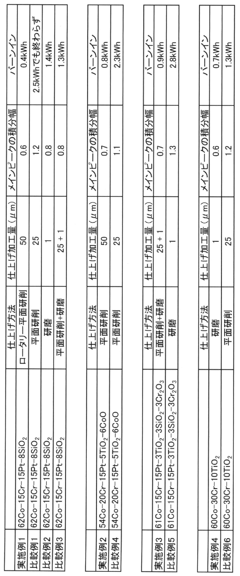
実施例1同様にして、組成が62Co-15Cr-15Pt-8SiO2(mol%)となるターゲット材料を作製した。但し、機械加工方法は旋盤加工の後、平面研削加工仕上げで作製した。仕上げ加工量は、25μmであった。このターゲット表面に残っている残留歪みを推定するためにXRD測定を行ったところ、単一のピークの中で最大である50°ピークの積分幅は1.2であり、本願発明の範囲を超えていた。このターゲットをスパッタリングした結果を表1に示す。2.5kWhスパッタリングしても、パーティクル数がバックグラウンドレベル(5個)以下に減少しなかった。
実施例1と同じ組成のターゲット材料を、機械加工方法は旋盤加工の後、研磨仕上げで作製した。仕上げ加工量は1μmであった。このターゲット表面に残っている残留歪みを推定するためにXRD測定を行ったところ、単一のピークの中で最大である50°ピークの積分幅は0.8であり、本願発明の範囲を超えていた。このターゲットをスパッタリングした結果を表1に示す。1.4kWhスパッタリングした時点でパーティクル数がバックグラウンドレベル(5個)以下に減少したが、実施例1に比べてバーンイン時間は長くなった。
実施例1と同じ組成のターゲット材を、機械加工方法は旋盤加工の後、平面研削加工を行ってから研磨仕上げで作製した。仕上げ加工量は25μm(平面研削)+1μm(研磨)であった。XRD測定の結果、単一のピークの中で最大である50°ピークの積分幅は0.8であり、本願発明の範囲を超えていた。
このターゲットをスパッタリングした結果、1.3kWhスパッタリングした時点でパーティクル数がバックグラウンドレベル(5個)以下に減少したが、実施例1に比べてバーンイン時間は長くなった。
原料粉末として、平均粒径3μmのCo粉末、平均粒径5μmのCr粉末、平均粒径1μmのPt粉末、平均粒径1μmのTiO2粉末、直径が50~300μmの範囲にあるCo粗粉を用意した。これらの粉末をターゲットの組成が54Co-20Cr-15Pt-5TiO2-6CoO(mol%)となるように、Co粉末、Cr粉末、Pt粉末、TiO2粉末、CoO粉末、Co粗粉を秤量した。以下、実施例1と同様にしてターゲット材を作製した。
このターゲットをスパッタリングした結果、0.8kWhスパッタリングした時点でパーティクル数がバックグラウンドレベル(5個)以下に減少し、良好な結果となった。以上の結果を、同様に表1に示す。
実施例2と同じ組成のターゲット材を、機械加工方法は、旋盤加工の後、平面研削加工で25μm切削することにより作製した。XRD測定の結果、単一のピークの中で最大である50°ピークの積分幅は1.1であり、本願発明の範囲を超えていた。
このターゲットをスパッタリングした結果、2.3kWhスパッタリングした時点でパーティクル数がバックグラウンドレベル(5個)以下に減少したが、実施例2に比べてバーンイン時間は長くなった。以上の結果を、同様に表1に示す。
原料粉末として、平均粒径3μmのCo粉末、平均粒径5μmのCr粉末、平均粒径1μmのPt粉末、平均粒径1μmのTiO2粉末、平均粒径1μmのSiO2粉末、平均粒径1μmのCr2O3粉末、直径が50~300μmの範囲にあるCo粗粉を用意した。これらの粉末をターゲットの組成が61Co-15Cr-15Pt-3TiO2-3SiO2-3Cr2O3(mol%)となるように、Co粉末、Cr粉末、Pt粉末、TiO2粉末、SiO2粉末、Cr2O3粉末、Co粗粉を秤量した。以下、実施例1と同様にしてターゲット材を作製した。
このターゲットをスパッタリングした結果、0.9kWhスパッタリングした時点でパーティクル数がバックグラウンドレベル(5個)以下に減少し、良好な結果となった。以上の結果を、同様に表1に示す。
実施例3と同じ組成のターゲット材を、機械加工方法は旋盤加工の後、平面研削加工のみで作製した。XRD測定の結果、単一のピークの中で最大である50°ピークの積分幅は1.3であり、本願発明の範囲を超えていた。
このターゲットをスパッタリングした結果、2.8kWhスパッタリングした時点でパーティクル数がバックグラウンドレベル(5個)以下に減少したが、実施例3に比べてバーンイン時間は長くなった。以上の結果を、同様に表1に示す。
原料粉末として、平均粒径3μmのCo粉末、平均粒径5μmのCr粉末、平均粒径1μmのTiO2粉末、直径が50~300μmの範囲にあるCo粗粉を用意した。これらの粉末をターゲットの組成が60Co-30Cr-10TiO2(mol%)となるように、Co粉末、Cr粉末、TiO2粉末、Co粗粉を秤量した。以下、実施例1と同様にしてターゲット材を作製した。
このターゲットをスパッタリングした結果、0.7kWhスパッタリングした時点でパーティクル数がバックグラウンドレベル(5個)以下に減少し、良好な結果が得られた。以上の結果を、同様に表1に示す。
実施例3と同じ組成のターゲットを、機械加工方法は旋盤加工の後、平面研削加工で作製した。仕上げ加工量は、25μmであった。XRD測定の結果、単一のピークの中で最大である50°ピークの積分幅は1.2であり、本願発明の範囲を超えていた。
このターゲットをスパッタリングした結果、1.3kWhスパッタリングした時点でパーティクル数がバックグラウンドレベル(5個)以下に減少し、実施例4に比べてバーンイン時間は長くなった。以上の結果を、同様に表1に示す。
さらに、SiO2、TiO2、Ti2O3、Cr2O3、Ta2O5、Ti5O9、B2O3、CoO、Co3O4から選択した一種以上の酸化物の添加についても、実施例以外に示す酸化物の添加についても、実施例と同様な結果が得られていることを確認している。
Claims (5)
- Coを含有する金属マトリックス相と、粒子を形成して分散して存在する6~25mol%の酸化物の相(以下、「酸化物相」という。)から構成されるスパッタリングターゲットであって、XRDの単一ピークの中で最も高いピークの積分幅が0.7以下であることを特徴とするスパッタリングターゲット。
- 金属マトリックス相が、Crが5mol%以上40mol%以下、残余がCo及び不可避的不純物であることを特徴とする請求項1記載のスパッタリングターゲット。
- 金属マトリックス相が、Crが5mol%以上40mol%以下、Ptが5mol%以上30mol%以下、残余がCo及び不可避的不純物であることを特徴とする請求項1記載のスパッタリングターゲット。
- 酸化物相が、SiO2、TiO2、Ti2O3、Cr2O3、Ta2O5、Ti5O9、B2O3、CoO、Co3O4から選択した一種以上の酸化物からなり、これらを5~25mol%含有することを特徴とする請求項1~3のいずれか一項に記載のスパッタリングターゲット。
- 金属マトリックス相が、B、Ti、V、Mn、Zr、Nb、Ru、Mo、Ta、Wから選択した1元素以上を、0.5mol%~10mol%含有することを特徴とする請求項1~4のいずれか一項に記載のスパッタリングターゲット。
Priority Applications (4)
| Application Number | Priority Date | Filing Date | Title |
|---|---|---|---|
| CN201380031894.4A CN104379801A (zh) | 2012-09-18 | 2013-09-13 | 溅射靶 |
| US14/402,024 US20150170890A1 (en) | 2012-09-18 | 2013-09-13 | Sputtering Target |
| JP2014512965A JP5960251B2 (ja) | 2012-09-18 | 2013-09-13 | スパッタリングターゲット |
| SG11201407011UA SG11201407011UA (en) | 2012-09-18 | 2013-09-13 | Sputtering target |
Applications Claiming Priority (2)
| Application Number | Priority Date | Filing Date | Title |
|---|---|---|---|
| JP2012204332 | 2012-09-18 | ||
| JP2012-204332 | 2012-09-18 |
Publications (1)
| Publication Number | Publication Date |
|---|---|
| WO2014046040A1 true WO2014046040A1 (ja) | 2014-03-27 |
Family
ID=50341353
Family Applications (1)
| Application Number | Title | Priority Date | Filing Date |
|---|---|---|---|
| PCT/JP2013/074840 Ceased WO2014046040A1 (ja) | 2012-09-18 | 2013-09-13 | スパッタリングターゲット |
Country Status (7)
| Country | Link |
|---|---|
| US (1) | US20150170890A1 (ja) |
| JP (1) | JP5960251B2 (ja) |
| CN (2) | CN104379801A (ja) |
| MY (1) | MY165736A (ja) |
| SG (1) | SG11201407011UA (ja) |
| TW (1) | TWI601839B (ja) |
| WO (1) | WO2014046040A1 (ja) |
Cited By (1)
| Publication number | Priority date | Publication date | Assignee | Title |
|---|---|---|---|---|
| WO2021014760A1 (ja) * | 2019-07-23 | 2021-01-28 | Jx金属株式会社 | 非磁性層形成用スパッタリングターゲット部材 |
Families Citing this family (7)
| Publication number | Priority date | Publication date | Assignee | Title |
|---|---|---|---|---|
| CN104975264B (zh) | 2010-07-29 | 2020-07-28 | 吉坤日矿日石金属株式会社 | 磁记录膜用溅射靶及其制造方法 |
| SG190773A1 (en) | 2010-12-21 | 2013-07-31 | Jx Nippon Mining & Metals Corp | Sputtering target for magnetic recording film, and process for production thereof |
| JP5646757B2 (ja) * | 2012-01-25 | 2014-12-24 | Jx日鉱日石金属株式会社 | 強磁性材スパッタリングターゲット |
| JP6504605B2 (ja) * | 2015-11-27 | 2019-04-24 | 田中貴金属工業株式会社 | スパッタリングターゲット |
| TWI671418B (zh) * | 2017-09-21 | 2019-09-11 | 日商Jx金屬股份有限公司 | 濺鍍靶、積層膜之製造方法、積層膜及磁記錄媒體 |
| JP6377231B1 (ja) * | 2017-10-23 | 2018-08-22 | デクセリアルズ株式会社 | Mn−Zn−W−O系スパッタリングターゲット及びその製造方法 |
| JP7242652B2 (ja) * | 2018-05-14 | 2023-03-20 | Jx金属株式会社 | スパッタリングターゲット及びスパッタリングターゲットの製造方法 |
Citations (7)
| Publication number | Priority date | Publication date | Assignee | Title |
|---|---|---|---|---|
| JPH01263269A (ja) * | 1988-04-15 | 1989-10-19 | Hitachi Ltd | スパッタリングターゲットの製造方法およびそれにより得られたスパッタリングターゲット |
| JP2003049264A (ja) * | 2000-09-07 | 2003-02-21 | Toshiba Corp | タングステンスパッタリングターゲットおよびその製造方法 |
| WO2007040014A1 (ja) * | 2005-10-04 | 2007-04-12 | Nippon Mining & Metals Co., Ltd. | スパッタリングターゲット |
| WO2009099121A1 (ja) * | 2008-02-08 | 2009-08-13 | Nippon Mining & Metals Co., Ltd. | イッテルビウム製スパッタリングターゲット及び同ターゲットの製造方法 |
| WO2011077933A1 (ja) * | 2009-12-25 | 2011-06-30 | Jx日鉱日石金属株式会社 | パーティクルの発生の少ないスパッタリングターゲット及び同ターゲットの製造方法 |
| WO2012011204A1 (ja) * | 2010-07-20 | 2012-01-26 | Jx日鉱日石金属株式会社 | パーティクル発生の少ない強磁性材スパッタリングターゲット |
| JP2012132036A (ja) * | 2010-12-20 | 2012-07-12 | Jx Nippon Mining & Metals Corp | 強磁性材スパッタリングターゲット |
Family Cites Families (9)
| Publication number | Priority date | Publication date | Assignee | Title |
|---|---|---|---|---|
| JP4907528B2 (ja) * | 2005-06-23 | 2012-03-28 | Jx日鉱日石金属株式会社 | スパッタリングターゲット |
| WO2009119812A1 (ja) * | 2008-03-28 | 2009-10-01 | 日鉱金属株式会社 | 非磁性材粒子分散型強磁性材スパッタリングターゲット |
| CN102105619B (zh) * | 2008-06-06 | 2014-01-22 | 出光兴产株式会社 | 氧化物薄膜用溅射靶及其制造方法 |
| MY149640A (en) * | 2009-12-11 | 2013-09-13 | Jx Nippon Mining & Metals Corp | Sputtering target comprising oxide phase dispersed in co or co alloy phase, magnetic thin film made of co or co alloy phase and oxide phase, and magnetic recording medium using the said thin film |
| JP4819199B1 (ja) * | 2010-07-20 | 2011-11-24 | Jx日鉱日石金属株式会社 | パーティクル発生の少ない強磁性材スパッタリングターゲット |
| US20130175167A1 (en) * | 2010-12-15 | 2013-07-11 | Jx Nippon Mining & Metals Corporation | Ferromagnetic sputtering target and method for manufacturing same |
| JP5394575B2 (ja) * | 2010-12-17 | 2014-01-22 | Jx日鉱日石金属株式会社 | 強磁性材スパッタリングターゲット |
| SG188603A1 (en) * | 2010-12-17 | 2013-04-30 | Jx Nippon Mining & Metals Corp | Ferromagnetic material sputtering target |
| US9732414B2 (en) * | 2012-01-18 | 2017-08-15 | Jx Nippon Mining And Metals Corporation | Co—Cr—Pt-based sputtering target and method for producing same |
-
2013
- 2013-09-13 SG SG11201407011UA patent/SG11201407011UA/en unknown
- 2013-09-13 US US14/402,024 patent/US20150170890A1/en not_active Abandoned
- 2013-09-13 WO PCT/JP2013/074840 patent/WO2014046040A1/ja not_active Ceased
- 2013-09-13 MY MYPI2014703787A patent/MY165736A/en unknown
- 2013-09-13 CN CN201380031894.4A patent/CN104379801A/zh active Pending
- 2013-09-13 JP JP2014512965A patent/JP5960251B2/ja active Active
- 2013-09-13 CN CN202011397506.2A patent/CN112695273A/zh active Pending
- 2013-09-16 TW TW102133475A patent/TWI601839B/zh active
Patent Citations (7)
| Publication number | Priority date | Publication date | Assignee | Title |
|---|---|---|---|---|
| JPH01263269A (ja) * | 1988-04-15 | 1989-10-19 | Hitachi Ltd | スパッタリングターゲットの製造方法およびそれにより得られたスパッタリングターゲット |
| JP2003049264A (ja) * | 2000-09-07 | 2003-02-21 | Toshiba Corp | タングステンスパッタリングターゲットおよびその製造方法 |
| WO2007040014A1 (ja) * | 2005-10-04 | 2007-04-12 | Nippon Mining & Metals Co., Ltd. | スパッタリングターゲット |
| WO2009099121A1 (ja) * | 2008-02-08 | 2009-08-13 | Nippon Mining & Metals Co., Ltd. | イッテルビウム製スパッタリングターゲット及び同ターゲットの製造方法 |
| WO2011077933A1 (ja) * | 2009-12-25 | 2011-06-30 | Jx日鉱日石金属株式会社 | パーティクルの発生の少ないスパッタリングターゲット及び同ターゲットの製造方法 |
| WO2012011204A1 (ja) * | 2010-07-20 | 2012-01-26 | Jx日鉱日石金属株式会社 | パーティクル発生の少ない強磁性材スパッタリングターゲット |
| JP2012132036A (ja) * | 2010-12-20 | 2012-07-12 | Jx Nippon Mining & Metals Corp | 強磁性材スパッタリングターゲット |
Cited By (2)
| Publication number | Priority date | Publication date | Assignee | Title |
|---|---|---|---|---|
| WO2021014760A1 (ja) * | 2019-07-23 | 2021-01-28 | Jx金属株式会社 | 非磁性層形成用スパッタリングターゲット部材 |
| JP7554192B2 (ja) | 2019-07-23 | 2024-09-19 | Jx金属株式会社 | 非磁性層形成用スパッタリングターゲット部材 |
Also Published As
| Publication number | Publication date |
|---|---|
| US20150170890A1 (en) | 2015-06-18 |
| JP5960251B2 (ja) | 2016-08-02 |
| MY165736A (en) | 2018-04-20 |
| JPWO2014046040A1 (ja) | 2016-08-18 |
| CN104379801A (zh) | 2015-02-25 |
| SG11201407011UA (en) | 2014-11-27 |
| TW201425618A (zh) | 2014-07-01 |
| CN112695273A (zh) | 2021-04-23 |
| TWI601839B (zh) | 2017-10-11 |
Similar Documents
| Publication | Publication Date | Title |
|---|---|---|
| JP5960251B2 (ja) | スパッタリングターゲット | |
| TWI496921B (zh) | Reduced Particle Generation of Strong Magnetic Sputtering Target | |
| JP5763178B2 (ja) | パーティクル発生の少ない強磁性材スパッタリングターゲット | |
| JP6037415B2 (ja) | 磁性材スパッタリングターゲット及びその製造方法 | |
| JP5290468B2 (ja) | C粒子が分散したFe−Pt系スパッタリングターゲット | |
| CN102471876B (zh) | 强磁性材料溅射靶 | |
| JP5457615B1 (ja) | 磁気記録膜形成用スパッタリングターゲット及びその製造方法 | |
| JP5394576B2 (ja) | 強磁性材スパッタリングターゲット | |
| WO2012011294A1 (ja) | パーティクル発生の少ない強磁性材スパッタリングターゲット | |
| JP5394575B2 (ja) | 強磁性材スパッタリングターゲット | |
| US20140083847A1 (en) | Fe-Pt-C Based Sputtering Target | |
| WO2012081340A1 (ja) | 磁気記録膜用スパッタリングターゲット及びその製造方法 | |
| JP5847203B2 (ja) | Co−Cr−Pt系スパッタリングターゲット及びその製造方法 | |
| WO2013125469A1 (ja) | 磁性材スパッタリングターゲット及びその製造方法 | |
| WO2014097911A1 (ja) | 焼結体スパッタリングターゲット | |
| JP6030271B2 (ja) | 磁性材スパッタリングターゲット | |
| JP4758522B1 (ja) | パーティクル発生の少ない強磁性材スパッタリングターゲット | |
| JP4819199B1 (ja) | パーティクル発生の少ない強磁性材スパッタリングターゲット |
Legal Events
| Date | Code | Title | Description |
|---|---|---|---|
| ENP | Entry into the national phase |
Ref document number: 2014512965 Country of ref document: JP Kind code of ref document: A |
|
| 121 | Ep: the epo has been informed by wipo that ep was designated in this application |
Ref document number: 13839888 Country of ref document: EP Kind code of ref document: A1 |
|
| WWE | Wipo information: entry into national phase |
Ref document number: 14402024 Country of ref document: US |
|
| NENP | Non-entry into the national phase |
Ref country code: DE |
|
| 122 | Ep: pct application non-entry in european phase |
Ref document number: 13839888 Country of ref document: EP Kind code of ref document: A1 |