WO2014034770A1 - 送風装置 - Google Patents
送風装置 Download PDFInfo
- Publication number
- WO2014034770A1 WO2014034770A1 PCT/JP2013/073123 JP2013073123W WO2014034770A1 WO 2014034770 A1 WO2014034770 A1 WO 2014034770A1 JP 2013073123 W JP2013073123 W JP 2013073123W WO 2014034770 A1 WO2014034770 A1 WO 2014034770A1
- Authority
- WO
- WIPO (PCT)
- Prior art keywords
- downstream
- upstream
- blade
- propeller fan
- wing
- Prior art date
- Legal status (The legal status is an assumption and is not a legal conclusion. Google has not performed a legal analysis and makes no representation as to the accuracy of the status listed.)
- Ceased
Links
Images






























Classifications
-
- A—HUMAN NECESSITIES
- A45—HAND OR TRAVELLING ARTICLES
- A45D—HAIRDRESSING OR SHAVING EQUIPMENT; EQUIPMENT FOR COSMETICS OR COSMETIC TREATMENTS, e.g. FOR MANICURING OR PEDICURING
- A45D20/00—Hair drying devices; Accessories therefor
- A45D20/04—Hot-air producers
- A45D20/08—Hot-air producers heated electrically
- A45D20/10—Hand-held drying devices, e.g. air douches
- A45D20/12—Details thereof or accessories therefor, e.g. nozzles, stands
-
- A—HUMAN NECESSITIES
- A45—HAND OR TRAVELLING ARTICLES
- A45D—HAIRDRESSING OR SHAVING EQUIPMENT; EQUIPMENT FOR COSMETICS OR COSMETIC TREATMENTS, e.g. FOR MANICURING OR PEDICURING
- A45D20/00—Hair drying devices; Accessories therefor
- A45D20/22—Helmets with hot air supply or ventilating means, e.g. electrically heated air current
- A45D20/34—Arrangements of the ventilating means
-
- F—MECHANICAL ENGINEERING; LIGHTING; HEATING; WEAPONS; BLASTING
- F04—POSITIVE - DISPLACEMENT MACHINES FOR LIQUIDS; PUMPS FOR LIQUIDS OR ELASTIC FLUIDS
- F04D—NON-POSITIVE-DISPLACEMENT PUMPS
- F04D17/00—Radial-flow pumps, e.g. centrifugal pumps; Helico-centrifugal pumps
- F04D17/06—Helico-centrifugal pumps
-
- F—MECHANICAL ENGINEERING; LIGHTING; HEATING; WEAPONS; BLASTING
- F04—POSITIVE - DISPLACEMENT MACHINES FOR LIQUIDS; PUMPS FOR LIQUIDS OR ELASTIC FLUIDS
- F04D—NON-POSITIVE-DISPLACEMENT PUMPS
- F04D29/00—Details, component parts, or accessories
- F04D29/26—Rotors specially for elastic fluids
- F04D29/28—Rotors specially for elastic fluids for centrifugal or helico-centrifugal pumps for radial-flow or helico-centrifugal pumps
- F04D29/281—Rotors specially for elastic fluids for centrifugal or helico-centrifugal pumps for radial-flow or helico-centrifugal pumps for fans or blowers
Definitions
- the present invention relates to a blower, and more particularly, to a blower that rotates a propeller fan using a drive motor.
- Patent Document 1 Japanese Utility Model Laid-Open No. 05-088404 (Patent Document 1) and Japanese Patent Application Laid-Open No. 2010-125134 (Patent Document 2) disclose an invention relating to a hair dryer.
- a blower such as a hair dryer includes a drive motor and a propeller fan.
- the propeller fan is attached to the output shaft of the drive motor.
- the propeller fan rotates in response to rotational power from the drive motor, and generates an airflow that flows from the suction port toward the discharge port.
- 1st and 2nd invention aims at providing the air blower which can suppress that foreign materials, such as the hair or dust which were suck
- a blower device includes an air passage forming member including an inlet and an outlet, an output shaft, a drive motor provided inside the air passage forming member, and an output shaft.
- a propeller fan that includes a boss portion to be attached and a wing portion provided on an outer surface of the boss portion, and is disposed closer to the suction port than the drive motor, and the propeller fan extends from the drive motor.
- An upstream end located on the side, an upstream surface that is continuous with the upstream end and extends outward in the radial direction of rotation of the propeller fan toward the downstream side, and downstream of the upstream surface And a downstream surface that connects the downstream end of the upstream surface and the downstream portion, and the downstream surface is along a direction parallel to the rotation axis. Or a shape extending toward the inner side in the rotational radial direction from the parallel direction toward the downstream portion.
- a blower device includes an air passage forming member including an inlet and an outlet, an output shaft, a drive motor provided inside the air passage forming member, and the output shaft.
- a propeller fan that includes a boss portion attached to the boss portion and a wing portion provided on an outer surface of the boss portion, and is disposed closer to the suction port than the drive motor, and the propeller fan includes the drive motor
- By generating rotational airflow from the upstream suction port to the downstream discharge port, and the outer surface of the boss portion is most
- An upstream end located upstream and having a planar shape and a shape extending along a direction parallel to the rotation axis, continuous with the outer edge of the upstream end, or as moving toward the downstream Parallel direction
- An upstream surface having a shape extending inward in the radial direction of rotation of the propeller fan, a downstream portion located downstream of the downstream end of the upstream surface, the downstream end of the upstream surface, and the downstream And the downstream surface has a shape extending toward the inner side in
- a blower device includes an air passage forming member including an inlet and an outlet, an output shaft, a drive motor provided inside the air passage forming member, and an output shaft.
- a propeller fan that includes a boss portion to be attached and a wing portion provided on an outer surface of the boss portion, and is disposed closer to the suction port than the drive motor, and the propeller fan extends from the drive motor.
- the airflow flowing from the upstream suction port toward the downstream discharge port is generated by rotating around a virtual rotation axis in response to the rotational power of the blade, and the wing portion is in the rotation direction of the propeller fan.
- a blade tip located at the most tip, a leading edge extending from the blade tip to the outer surface of the boss, and forming a leading edge of the blade in the rotational direction; and the boss Outer surface Extending from the propeller fan to the outside in the radial direction of rotation, and connecting the trailing edge forming the trailing edge of the blade in the rotational direction, the blade tip and the outer edge of the trailing edge And an outer peripheral edge portion forming an outer peripheral edge of the wing portion in the rotational radius direction, and the most downstream position and the leading edge in the wing portion in a direction parallel to the rotation axis If the height dimension between the root position of the part is ha and the height dimension between the most downstream position in the wing part and the position of the blade tip part is hb, the value of hb / ha Is 1.5 or more.
- a blower device includes an air passage forming member including an inlet and an outlet, an output shaft, a drive motor provided inside the air passage forming member, and the output shaft.
- a propeller fan that includes a boss portion attached to the boss portion and a wing portion provided on an outer surface of the boss portion, and is disposed closer to the suction port than the drive motor, and the propeller fan includes the drive motor
- the airflow flowing from the upstream suction port to the downstream discharge port is generated by rotating around the virtual rotation axis in response to rotational power from the blade, and the wing portion rotates in the direction of the propeller fan.
- an outer peripheral edge portion forming an outer peripheral edge of the wing portion in the rotational radius direction, and the air passage forming member includes an inner wall portion and a concave portion provided to be recessed from the inner wall portion.
- the most downstream part of the recess is located on the upstream side of the most downstream part of the boss part, and the wing part
- the most upstream part of the recess is located on the upstream side of the blade tip part of the blade part in the direction parallel to the rotation axis and located on the downstream side of the blade tip part.
- a blower device includes an air passage forming member including an inlet and an outlet, an output shaft, a drive motor provided inside the air passage forming member, and the output
- a propeller fan including a boss portion attached to a shaft and a wing portion provided on an outer surface of the boss portion, and disposed closer to the suction port than the drive motor, the propeller fan including the drive
- a blade tip located at the most tip in the direction, a leading edge extending from the blade tip to the outer surface of the boss, and forming a leading edge of the blade in the rotational direction; and the boss upon A rear edge portion extending from the outer surface toward the outer side in the rotational radius direction of the propeller fan, forming a rear edge of the blade portion in the rotational direction, the blade tip portion, and an outer end of the rear edge portion;
- an outer peripheral edge portion that forms an outer peripheral edge of the wing portion in the rotational radius direction, and the air passage forming member includes a first inner wall portion, and the downstream side of the first inner wall portion.
- a second inner wall portion having a narrower air passage area than the first inner wall portion, and in the direction parallel to the rotation axis, the most upstream portion of the second inner wall portion Is positioned on the upstream side of the most downstream portion of the boss portion and on the downstream side of the blade tip portion of the blade portion.
- a blower device includes an air passage forming member including an inlet and an outlet, an output shaft, a drive motor provided inside the air passage forming member, and a boss attached to the output shaft. And a propeller fan disposed on the inlet side of the drive motor, the propeller fan including rotational power from the drive motor. Receiving and rotating around a virtual rotation axis to generate an air flow flowing from the upstream suction port toward the downstream discharge port, and is disposed on the downstream side of the propeller fan, and is connected to the upstream edge portion.
- the wing portion further includes a wing tip portion positioned at the most tip in the rotation direction of the propeller fan, and from the blade tip portion to the outer surface of the boss portion.
- a front edge portion that extends and forms a front edge of the wing portion in the rotational direction, and extends from the outer surface of the boss portion toward the outer side in the rotational radial direction of the propeller fan, in the rotational direction.
- a rear edge part forming a rear edge of the wing part, an outer peripheral part connecting the wing tip part and an outer end of the rear edge part, and forming an outer peripheral edge of the wing part in the rotational radius direction;
- Each of the trailing edge portion of the wing portion and the upstream edge portion of the rectifying blade is viewed from a direction perpendicular to the rotation axis in a state where they are opposed to each other.
- the rotating shaft It has a shape in which only each other some of these when viewed them from the direction parallel to intersect against.
- the blower capable of suppressing foreign matter such as hair or dust sucked together with air from the suction port from being entangled with the output shaft of the drive motor.
- the third invention it is possible to obtain a blower that can suppress the generation of noise from the propeller fan.
- FIG. 3 is a cross-sectional view showing the air blower in the first embodiment. It is sectional drawing which expands and shows the area
- FIG. 3 is a side view showing a propeller fan used in the air blower in the first embodiment.
- FIG. 2 is a plan view showing a propeller fan used in the blower in Embodiment 1.
- FIG. It is sectional drawing which shows a mode when the propeller fan used for the air blower in Embodiment 1 is rotating. It is a figure which shows typically a mode when the boss
- 6 is a diagram schematically showing a boss portion in a first modification of the first embodiment.
- FIG. It is a figure which shows typically the boss
- FIG. 1 It is a figure which shows typically the boss
- FIG. It is a figure which shows typically the boss
- FIG. It is a figure which shows typically the boss
- FIG. It is a figure which shows typically the boss
- FIG. It is a figure which shows typically the boss
- FIG. It is a figure which shows typically the boss
- FIG. It is a figure which shows typically the boss
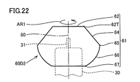
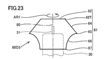
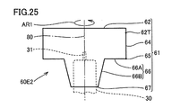
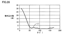
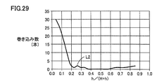
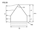
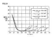
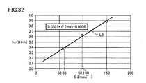
- FIG. 6 is a diagram schematically showing a boss portion used in Experimental example 1 related to the first embodiment. It is a figure which shows the conditions and result of Experimental example 1 regarding Embodiment 1, and has shown the relationship between the internal angle of an upstream edge part, and the number of the hair wound in the output shaft of a drive motor. It is a figure which shows the conditions and result of Experimental example 1 regarding Embodiment 1, and has shown the relationship between the value of h / (H + h) and the number of the hairs wound in the output shaft of a drive motor. It is a figure which shows typically the boss
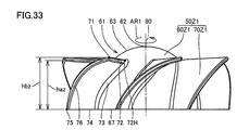
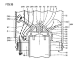
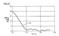
- FIG. 6 is a side view showing a propeller fan used in a blower device in a second embodiment. It is sectional drawing which shows a mode when the propeller fan used for the air blower in Embodiment 2 is rotating. It is a figure which shows the conditions and result of Experimental example 3 regarding Embodiment 2, and has shown the relationship between the value of hb / ha and the number of the hair caught in the output shaft of a drive motor. It is a figure which shows partially the air blower used for Experimental example 4 regarding Embodiment 2. FIG. It is a figure which shows the conditions and result of Experimental example 4 regarding Embodiment 2. FIG. It is a top view which shows the propeller fan used for the air blower in the comparative example 3. FIG.
- FIG. 10 is a plan view showing a propeller fan in a first modification example of the second embodiment.
- FIG. 11 is a plan view showing a state when the propeller fan in the first modification of the second embodiment is rotating. It is a figure which shows partially the air blower in the 2nd modification of Embodiment 2.
- FIG. It is a figure which shows partially the air blower in the 3rd modification of Embodiment 2.
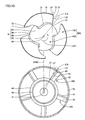
- FIG. It is a top view which shows the propeller fan and rectifier blade in Embodiment 3 (The state where the propeller fan is not attached to the drive motor is shown).
- It is a top view which shows the propeller fan and rectifier blade in Embodiment 3 (The state where the propeller fan is attached to the drive motor is shown).
- FIG. 10 is a plan view schematically showing a propeller fan and a rectifying blade in a first modification of the third embodiment.
- FIG. 10 is a plan view schematically showing a propeller fan and a rectifying blade in a second modification example of the third embodiment.
- FIG. 10 is a plan view schematically showing a propeller fan and a rectifying blade in a third modification of the third embodiment.
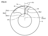
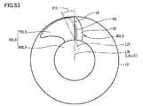
- FIG. 10 is a plan view schematically showing a propeller fan and a rectifying blade in a fourth modification example of the third embodiment.
- FIG. 10 is a plan view schematically showing a propeller fan and a rectifying blade in a first modification of the third embodiment.
- FIG. 10 is a plan view schematically showing a propeller fan and a rectifying blade in a second modification example of the third embodiment.
- FIG. 10 is a plan view schematically showing a propeller fan and a rectifying blade in a third modification of the third embodiment.
- FIG. 10 is a plan view schematically showing a
- FIG. 25 is a plan view schematically showing a propeller fan and a rectifying blade in a fifth modification example of the third embodiment.
- FIG. 25 is a plan view schematically showing a propeller fan and a rectifying blade in a sixth modification example of the third embodiment.
- FIG. 25 is a plan view schematically showing a propeller fan and a rectifying blade in a seventh modification example of the third embodiment.
- FIG. 29 is a plan view schematically showing a wing part of a propeller fan and an upstream edge part of a rectifying blade in an eighth modification example of the third embodiment.
- FIG. 25 is a plan view schematically showing a wing part of a propeller fan and an upstream edge part of a rectifying blade in a ninth modification example of the third embodiment.
- FIG. 25 is a plan view schematically showing a wing part of a propeller fan and an upstream edge part of a rectifying blade in a ninth modification example of the third embodiment.
- FIG. 29 is a plan view schematically showing a blade portion of a propeller fan and an upstream edge portion of a rectifying blade in a tenth modification example of the third embodiment.
- FIG. 25 is a plan view schematically showing a blade portion of a propeller fan and an upstream edge portion of a rectifying blade in an eleventh modification example of the third embodiment.
- FIG. 29 is a plan view schematically showing a blade portion of a propeller fan and an upstream edge portion of a rectifying blade in a twelfth modification of the third embodiment.
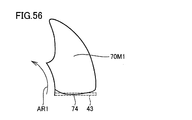
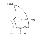
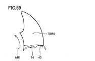
- FIG. 38 is a plan view schematically showing a blade portion of a propeller fan and an upstream edge portion of a rectifying blade in a thirteenth modification example of the third embodiment.
- FIG. 25 is a plan view schematically showing a blade portion of a propeller fan and an upstream edge portion of a rectifying blade in an eleventh modification example of the third embodiment.
- FIG. 29 is a plan view schematically showing a blade portion of a
- FIG. 29 is a plan view schematically showing a blade portion of a propeller fan and an upstream edge portion of a rectifying blade in a fourteenth modified example of the third embodiment.
- FIG. 29 is a plan view schematically showing a blade portion of a propeller fan and an upstream edge portion of a rectifying blade in a fifteenth modification example of the third embodiment.
- FIG. 38 is a plan view schematically showing a blade portion of a propeller fan and an upstream edge portion of a rectifying blade in a sixteenth modification example of the third embodiment.
- FIG. 6 is a cross-sectional view showing a propeller fan and a rectifying blade in a fourth embodiment.
- FIG. 6 is an enlarged cross-sectional view showing a propeller fan and a rectifying blade in a fourth embodiment.
- FIG. 10 is a cross-sectional view showing a propeller fan and a rectifying blade in a first modification of the fourth embodiment.
- FIG. 10 is a cross-sectional view showing a propeller fan and a rectifying blade in a second modification of the fourth embodiment.
- FIG. 10 is a cross-sectional view showing a propeller fan and a rectifying blade in a third modification of the fourth embodiment.
- FIG. 10 is a cross-sectional view showing a propeller fan and a rectifying blade in a fourth modification of the fourth embodiment.
- FIG. 10 is a cross-sectional view showing a propeller fan and a rectifying blade in a fifth modification of the fourth embodiment.
- FIG. 10 is a cross-sectional view showing a propeller fan and a rectifying blade in a fifth modification of the fourth embodiment.
- FIG. 25 is a side view schematically showing a blade portion and a rectifying blade of a propeller fan in a sixth modification example of the fourth embodiment.
- FIG. 25 is a side view schematically showing a blade portion and a rectifying blade of a propeller fan in a seventh modification example of the fourth embodiment.
- FIG. 29 is a side view schematically showing a wing part and a rectifying blade of a propeller fan in an eighth modification example of the fourth embodiment.
- FIG. 25 is a side view schematically showing a blade portion and a rectifying blade of a propeller fan in a ninth modification example of the fourth embodiment.
- FIG. 29 is a side view schematically showing a propeller fan blade and a rectifying blade in a tenth modification of the fourth embodiment.
- FIG. 29 is a side view schematically showing a propeller fan blade and a rectifying blade in a tenth modification of the fourth embodiment.
- FIG. 29 is a side view schematically showing a blade portion and a rectifying blade of a propeller fan in an eleventh modification example of the fourth embodiment.
- FIG. 25 is a side view schematically showing a propeller fan blade portion and a rectifying blade in a twelfth modification of the fourth embodiment.
- FIG. 25 is a side view schematically showing a blade portion and a rectifying blade of a propeller fan in a thirteenth modification example of the fourth embodiment.
- FIG. 25 is a side view schematically showing a blade portion and a rectifying blade of a propeller fan in a fourteenth modification example of the fourth embodiment.
- FIG. 1 is a cross-sectional view showing an air blower 100 in this comparative example.
- the blower 100 includes a main body 10 and a grip 20.
- the grip part 20 is a part gripped by the user.
- An operation unit 23 is provided on the surface of the grip unit 20.
- the tip 21 of the grip 20 is rotatably attached to the main body 10.
- a power cord 24 is provided at the rear end 22 of the grip 20.
- the main body 10 includes an outer case 11, an inner case 12, a drive motor 30, a propeller fan 50Z, a rectifying blade 40Z, and a heater 17.
- the outer case 11 and the inner case 12 each have a substantially cylindrical shape.
- the outer case 11 has an inlet opening 13 and an outlet opening 14.
- the inlet opening 13 communicates with the outlet opening 14, and an air passage is formed between the inlet opening 13 and the outlet opening 14.
- the inner case 12 as a wind path forming member is disposed inside the outer case 11.
- the inner case 12 has a suction port 15 and a discharge port 16. In a state where the inner case 12 is disposed inside the outer case 11, the suction port 15 is located on the inlet opening 13 side of the outer case 11, and the discharge port 16 is located on the outlet opening 14 side of the outer case 11.
- the drive motor 30, the propeller fan 50Z, and the rectifying blades 40Z are provided inside the inner case 12.
- a motor support 44 (see FIG. 2) is provided inside the rectifying blade 40Z.
- the drive motor 30 is supported by the motor support portion 44.
- the drive motor 30 is arranged such that its output shaft 31 (see FIG. 2) is substantially parallel to the longitudinal direction of the main body 10.
- the propeller fan 50Z is attached to the drive motor 30.
- Propeller fan 50Z is disposed closer to suction port 15 than drive motor 30 is.
- the propeller fan 50Z is disposed such that the rotation axis of the propeller fan 50Z (see the rotation axis 80 in FIG. 2) is substantially parallel to the longitudinal direction of the main body portion 10.
- the drive motor 30 rotates the propeller fan 50 ⁇ / b> Z by being supplied with power through the power cord 24.
- the propeller fan 50Z receives the rotational power from the drive motor 30 and rotates around the rotation axis, and the airflow (air) flowing from the upstream inlet opening 13 and the suction port 15 toward the downstream discharge port 16 and the outlet opening 14 Flow).
- the heater 17 is disposed closer to the outlet opening 14 than the propeller fan 50Z.
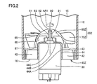
- FIG. 2 is an enlarged cross-sectional view showing a region surrounded by line II in FIG.
- the cross-sectional view of FIG. 2 is illustrated such that the suction port 15 is located above the paper surface and the discharge port 16 is located below the paper surface.
- the drive motor 30, the propeller fan 50Z, and the rectifying blade 40Z are provided inside the inner case 12.
- a motor support 44 is provided inside the rectifying blade 40Z.
- the motor support 44 has a peripheral wall 44A, a bottom wall 44B, and a hole 44C.
- the peripheral wall 44A has a cylindrical shape.
- the central axis of the peripheral wall 44A and the central axis of the inner case 12 are located on substantially the same straight line.
- the bottom wall 44B has a disc shape and is provided so as to close the upstream end of the peripheral wall 44A.
- the hole 44C is provided at the center of the bottom wall 44B.
- the rectifying blade 40Z is disposed downstream of the propeller fan 50Z.
- the rectifying blade 40 ⁇ / b> Z includes a plate-like portion 42.
- the plate-like portion 42 extends radially outward from the outer surface of the motor support portion 44 (circumferential wall 44A).
- the plate-like portions 42 are arranged at intervals in the circumferential direction so as not to reduce the flow rate of the airflow flowing from the suction port 15 toward the discharge port 16.
- the plate-like portion 42 has an upstream edge portion 43 on the upstream side.
- the upstream edge portion 43 of this comparative example has a planar shape and extends along a direction perpendicular to the rotation shaft 80 of the propeller fan 50Z.
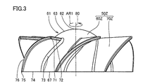
- FIG. 3 is a side view showing the propeller fan 50Z.
- FIG. 4 is a plan view showing the propeller fan 50Z.
- Propeller fan 50Z is integrally manufactured as a resin molded product using a synthetic resin such as an AS (acrylonitrile-styrene) resin. Propeller fan 50Z receives rotational power from drive motor 30 (see FIG. 2) and rotates in the direction of arrow AR1 around rotating shaft 80 (see FIG. 3).
- the propeller fan 50Z includes a boss portion 60Z and seven wing portions 70Z.
- the propeller fan 50Z in this comparative example has a rotationally symmetric shape.
- Boss 60Z The boss portion 60 ⁇ / b> Z rotates in the direction of the arrow AR ⁇ b> 1 about the virtual rotation shaft 80 by receiving the rotational power from the drive motor 30.
- Boss portion 60 ⁇ / b> Z includes an outer surface 61, an inner surface 68 and a bearing portion 69.
- the boss part 60Z has a rotationally symmetric shape as a whole, and the outer surface 61 of the boss part 60Z has a hemispherical shape as a whole.
- An upstream end 62 is formed at the most upstream position (vertex) of the outer surface 61.
- a rotation shaft 80 is formed so as to pass through the upstream end 62 when the propeller fan 50Z is rotating.
- a main flow surface 63 is formed at an intermediate position of the outer surface 61 in a direction parallel to the rotation shaft 80.
- the main flow surface 63 has a hemispherical shape continuous to the upstream end portion 62, and extends so as to increase in diameter toward the outer side in the rotational radial direction of the propeller fan 50Z toward the downstream side.
- a downstream portion 67 is formed at the most downstream position of the outer surface 61.
- the downstream portion 67 is located at the downstream end of the main flow surface 63. When the downstream portion 67 is viewed in plan (see FIG. 4), the downstream portion 67 has a circular shape.
- the inner surface 68 of the boss portion 60Z is formed inside the outer surface 61.
- the bearing portion 69 has a cylindrical shape and is provided at the center position of the inner surface 68.
- the bearing portion 69 is a part that connects the propeller fan 50Z to the output shaft 31 (see FIG. 2) of the drive motor 30 (see FIG. 2).
- the seven blade portions 70Z are provided on the outer surface 61 of the boss portion 60Z, and have a shape extending from the outer surface 61 toward the outer side in the rotational radius direction of the propeller fan 50Z.
- the seven wing portions 70Z have the same shape.
- the seven blade portions 70Z are arranged side by side at equal intervals in the rotation direction of the propeller fan 50Z (arrow AR1 direction).
- the wing part 70Z has a wing tip part 71, a leading edge part 72, a root part 73, a trailing edge part 74, a wing trailing edge part 75, and an outer peripheral edge part 76.
- the blade tip 71 is located at the most tip (front side) in the rotation direction (arrow AR1 direction) of the propeller fan 50Z.
- the leading edge 72 extends from the blade tip 71 to the outer surface 61 of the boss 60Z, and forms the leading edge of the blade 70Z in the rotational direction.
- the front edge portion 72 of the present comparative example extends so as to be substantially along a direction perpendicular to the rotation shaft 80 of the propeller fan 50Z (see FIG. 3).
- the root portion 73 is formed (boundary) between the wing portion 70Z and the outer surface 61 of the boss portion 60Z.
- the trailing edge portion 74 extends from the outer surface 61 of the boss portion 60Z toward the outer side in the rotational radius direction, and forms a trailing edge of the blade portion 70Z in the rotation direction (arrow AR1 direction) of the propeller fan 50Z.
- the rear edge portion 74 of this comparative example is connected to the rotation shaft 80 of the propeller fan 50Z. It extends along a direction perpendicular to the surface (see FIG. 3).
- the blade trailing edge 75 is formed at the outermost edge (outer edge) of the trailing edge 74 in the rotational radius direction.
- the outer peripheral edge 76 connects the blade tip 71 and the blade trailing edge 75, and forms the outer periphery of the blade 70Z in the rotational radius direction.
- the wing part 70Z has a sickle shape with the wing tip part 71 as a tip.
- the wing portion 70 ⁇ / b> Z has a shape in which the width in the direction along the rotation direction between the front edge portion 72 and the rear edge portion 74 gradually decreases toward the inner side in the rotation radius direction.
- the wing portion 70 ⁇ / b> Z has a shape in which the width in the direction along the rotational direction between the front edge portion 72 and the rear edge portion 74 gradually increases toward the outside in the rotational radius direction.
- the front edge portion 72 is located on the front side in the rotation direction (arrow AR1 direction) of the wing portion 70Z, and forms the front edge of the wing portion 70Z in the rotation direction.
- the front edge portion 72 has a front end portion in the rotation direction of the root portion 73. As a starting point, it extends substantially linearly from the inner side in the rotational radius direction toward the outer side in the same direction.
- the front edge portion 72 of this comparative example is the same as the propeller fan 50Z. It extends so as to be substantially along a direction perpendicular to the rotation shaft 80 (see FIG. 3).
- the blade tip 71 is located at the most tip (front side) of the blade 70Z in the rotation direction (arrow AR1 direction) and at the outermost side in the rotation radius direction at the leading edge 72.
- the blade tip portion 71 is a portion where the front edge portion 72 and the outer peripheral edge portion 76 are connected, and is a portion where the radius of curvature is minimized between the front edge portion 72 and the outer peripheral edge portion 76.
- the trailing edge portion 74 is located on the rear side in the rotation direction (arrow AR1 direction) of the wing portion 70Z, and forms the trailing edge of the wing portion 70Z in the rotation direction.
- the rear edge portion 74 is the rear end portion in the rotation direction of the root portion 73. Starting from the inside in the radial direction of rotation and extending outward in the same direction.
- the trailing edge portion 74 of this comparative example is the same as the propeller fan 50Z. It extends linearly along a direction perpendicular to the rotation shaft 80 (see FIG. 3).
- the blade trailing end 75 is located on the outermost side in the radial direction of rotation at the trailing edge 74.
- the blade trailing end portion 75 is a portion where the trailing edge portion 74 and the outer peripheral edge portion 76 are connected, and is a portion where the radius of curvature is minimized between the trailing edge portion 74 and the outer peripheral edge portion 76.
- the blade tip portion 71 and the blade trailing end portion 75 are located on substantially the same circle.
- the outer peripheral edge portion 76 extends along the rotation direction of the wing portion 70Z (the circumferential direction around the rotation shaft 80), and is provided so as to connect between the wing tip portion 71 and the wing rear end portion 75.
- the outer peripheral edge portion 76 of this comparative example extends in an arc shape between the blade tip portion 71 and the blade trailing end portion 75 as a whole.
- the rotation shaft 80 (upstream end portion 62) and the blade tip portion 71 are The dimension between them and the dimension between the rotary shaft 80 (upstream end 62) and the blade trailing end 75 are the same value.
- the blade tip 71, the leading edge 72, the root 73, the trailing edge 74, the blade trailing edge 75, and the outer peripheral edge 76 form the periphery of the blade 70Z.
- the wing surface of the wing part 70Z is formed in the entire region inside the region surrounded by the periphery.
- the blade surface of the wing portion 70Z has a shape in which the leading edge portion 72 is located on the upstream side in the airflow direction and the trailing edge portion 74 is located on the downstream side in the airflow direction. In other words, the blade surface of the wing portion 70Z as a whole moves from the suction port 15 (see FIG. 2) side to the discharge port 16 (see FIG. 2) side as it goes from the front edge portion 72 to the rear edge portion 74. It is formed to be smoothly curved (see FIG. 3).
- a pressure surface is formed on the surface of the blade surface of the blade portion 70Z on the discharge port 16 side, and a suction surface is formed on the surface of the suction port 15 of the blade surface.
- the blade surface of the blade portion 70Z generates an airflow that flows from the suction port 15 toward the discharge port 16.
- propeller fan 50Z is rotating, an air flow is generated on the blade surface, and a pressure distribution that is relatively large on the pressure surface and relatively small on the suction surface is generated.
- FIG. 5 is a cross-sectional view showing a state when the propeller fan 50Z is rotating.
- Propeller fan 50Z receives rotational power from drive motor 30 and rotates in the direction of arrow AR1, and generates an airflow (see arrow DR1) that flows from suction port 15 toward discharge port 16. As indicated by the arrow DR1, the airflow from the suction port 15 flows from the upstream side toward the downstream side along the blade surface of the blade portion 70Z and the outer surface 61 of the boss portion 60Z.
- a blade tip vortex is generated in the vicinity of the blade tip 71 (see FIGS. 3 and 4) of the blade 70Z (see arrow DR3).
- the blade tip vortex is generated so as to extend toward the rear side in the rotation direction (arrow AR1 direction) with the vicinity of the blade tip 71 as a tip.
- FIG. 6 is a diagram schematically illustrating a state in which a part of the air flowing along the outer surface 61 is sucked into the boss portion 60Z.
- the outer surface 61 of the boss portion 60Z has a hemispherical shape as a whole, so that a part of the air flowing along the outer surface 61 is It flows around the downstream portion 67 of 60Z so as to be sucked into the boss portion 60Z.
- the outer surface 61 of the boss portion 60ZA has a cylindrical surface shape as a whole.
- the outer surface 61 of the boss portion 60ZA includes an upstream end portion 62, a main flow surface 63, and a downstream portion 67.
- the upstream end portion 62 is located on the most upstream side of the boss portion 60ZA and has a planar shape.
- the main flow surface 63 is continuous with the outer edge of the upstream end portion 62 and has a shape extending along a direction parallel to the rotation axis 80.
- the downstream portion 67 is located at the downstream end of the main flow surface 63.
- the air present inside the boss portion 60ZA is also rotated by the inner surface of the boss portion 60ZA. Centrifugal force is generated in the air existing inside the boss portion 60ZA as it rotates. A negative pressure is generated in the vicinity of the downstream portion 67 of the boss portion 60ZA by the air in which the centrifugal force is generated and the air flowing through the space around the boss portion 60ZA where the wing portion is not provided. In the vicinity of the downstream portion 67 of the boss portion 60ZA, a vortex is generated by the action of this negative pressure.
- the outer surface 61 of the boss portion 60ZA has a cylindrical surface shape as a whole, so that part of the air flowing along the outer surface 61 is downstream of the boss portion 60ZA. It folds around 67 and flows so as to be sucked into the boss 60ZA. Foreign matter such as hair may be sucked into the boss portion 60ZA by the air flow indicated by the arrow DR4 and entangled with the output shaft 31 of the drive motor 30.
- the outer surface 61 of the boss 60ZB has a conical shape as a whole.
- the outer surface 61 of the boss portion 60ZB includes an upstream end portion 62, a main flow surface 63, and a downstream portion 67.
- the upstream end portion 62 is located on the most upstream side of the boss portion 60ZB.
- the main flow surface 63 is continuous with the upstream end portion 62 and extends so as to increase in diameter toward the outer side in the rotational radial direction toward the downstream side.
- the downstream portion 67 is located at the downstream end of the main flow surface 63.
- the air existing inside the boss 60ZB is also rotated by the inner surface of the boss 60ZB. Centrifugal force is generated in the air existing inside the boss portion 60ZB as it rotates. A negative pressure is generated in the vicinity of the downstream portion 67 of the boss portion 60ZB by the air in which the centrifugal force is generated and the air flowing through the space around the boss portion 60ZB where no wing portion is provided. In the vicinity of the downstream portion 67 of the boss portion 60ZB, a vortex is generated by the action of this negative pressure.
- the outer surface 61 of the boss portion 60ZB has a conical shape as a whole, so that part of the air flowing along the outer surface 61 is downstream of the boss portion 60ZB. It folds around 67 and flows so as to be sucked into the boss 60ZB. Foreign matter such as hair may be sucked into the boss portion 60ZB on the air flow indicated by the arrow DR4 and entangled with the output shaft 31 of the drive motor 30.
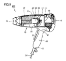
- FIG. 9 is a cross-sectional view showing a blower device 200 in the present embodiment.
- the blower device 200 includes a main body 10 and a grip 20.
- the grip part 20 is a part gripped by the user.
- An operation unit 23 is provided on the surface of the grip unit 20.
- the tip 21 of the grip 20 is rotatably attached to the main body 10.
- a power cord 24 is provided at the rear end 22 of the grip 20.
- the main body 10 and the gripper 20 form a substantially T-shape or a substantially L-shape as a whole.
- the grip 20 can be rotated to a position along the main body 10.
- the air blower 200 can be easily accommodated by folding the grip 20.
- the main body 10 includes an outer case 11, an inner case 12, a drive motor 30, a propeller fan 50, a rectifying blade 40 and a heater 17.
- the outer case 11 and the inner case 12 each have a substantially cylindrical shape.
- the outer case 11 has an inlet opening 13 and an outlet opening 14.
- the inlet opening 13 communicates with the outlet opening 14, and an air passage is formed between the inlet opening 13 and the outlet opening 14.
- the inner case 12 as a wind path forming member is disposed inside the outer case 11.
- the inner case 12 has a suction port 15 and a discharge port 16. In a state where the inner case 12 is disposed inside the outer case 11, the suction port 15 is located on the inlet opening 13 side of the outer case 11, and the discharge port 16 is located on the outlet opening 14 side of the outer case 11.
- the drive motor 30, the propeller fan 50 and the rectifying blade 40 are provided inside the inner case 12.
- a motor support 44 (see FIG. 10) is provided inside the rectifying blade 40.
- the drive motor 30 is supported by the motor support portion 44.
- the drive motor 30 is arranged such that its output shaft 31 (see FIG. 10) is substantially parallel to the longitudinal direction of the main body 10.
- the propeller fan 50 is attached to the drive motor 30.
- the propeller fan 50 is disposed closer to the suction port 15 than the drive motor 30.
- Propeller fan 50 is arranged such that the rotation axis of propeller fan 50 (see rotation axis 80 in FIG. 10) is substantially parallel to the longitudinal direction of main body 10.
- the drive motor 30 rotates the propeller fan 50 by being supplied with power through the power cord 24.
- the propeller fan 50 receives the rotational power from the drive motor 30 and rotates around the rotation axis, and the airflow (air) flowing from the upstream side inlet opening 13 and the suction port 15 toward the downstream side discharge port 16 and the outlet opening 14. Flow).
- the heater 17 is disposed closer to the outlet opening 14 than the propeller fan 50.
- the operating state of the heater 17 is switched by operating the operation unit 23.
- warm air is blown out from the outlet opening 14.
- cold air is blown out from the outlet opening 14.
- the operation state of the heater 17 may include a mode in which the ON state and the OFF state are periodically switched. As the temperature of the wind blown from the outlet opening 14 changes with time, the warmed scalp is tightened with cold air, the warmed hair is tightened, a cuticle is formed on the hair, etc. It becomes possible.
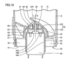
- FIG. 10 is an enlarged sectional view showing a region surrounded by X-rays in FIG.
- the cross-sectional view of FIG. 10 is illustrated such that the suction port 15 is located above the paper surface and the discharge port 16 is located below the paper surface.
- the drive motor 30, the propeller fan 50, and the rectifying blade 40 are provided inside the inner case 12.
- a motor support 44 is provided inside the rectifying blade 40.
- the motor support 44 has a peripheral wall 44A, a bottom wall 44B, a hole 44C, and an annular wall 46.
- the peripheral wall 44A has a cylindrical shape.
- the central axis of the peripheral wall 44A and the central axis of the inner case 12 are located on substantially the same straight line.
- the bottom wall 44B has a disc shape and is provided so as to close the upstream end of the peripheral wall 44A.
- the hole 44C is provided at the center of the bottom wall 44B.
- the rectifying blade 40 is disposed on the downstream side of the propeller fan 50.
- the rectifying blade 40 includes a plate-like portion 42.
- the plate-like portion 42 extends radially outward from the outer surface of the motor support portion 44 (circumferential wall 44A).
- the plate-like portions 42 are arranged at intervals in the circumferential direction so as not to reduce the flow rate of the airflow flowing from the suction port 15 toward the discharge port 16.
- the plate-like portion 42 has an upstream edge portion 43 on the upstream side.
- the upstream edge 43 of the present embodiment has a planar shape and extends along a direction perpendicular to the rotation shaft 80 of the propeller fan 50.
- FIG. 11 is a side view showing the propeller fan 50.
- FIG. 12 is a plan view showing the propeller fan 50.
- the propeller fan 50 is integrally manufactured as a resin molded product using a synthetic resin such as an AS (acrylonitrile-styrene) resin.
- the propeller fan 50 receives rotational power from the drive motor 30 (see FIG. 10) and rotates around the rotation shaft 80 (see FIG. 11) in the direction of the arrow AR1.
- the propeller fan 50 includes a boss portion 60 and three wing portions 70.
- Propeller fan 50 in the present embodiment has a rotationally symmetric shape.
- the propeller fan 50 may be manufactured, for example, by twisting a single sheet metal, or may be manufactured from an integral thin-walled object formed with a curved surface. In these cases, the propeller fan may have a structure in which three blade portions 70 are joined to a separately formed boss portion 60.
- the propeller fan 50 may include a plurality of blade portions 70 other than three, or may include only one blade portion 70.
- a weight as a balancer may be provided on the opposite side of the wing portion 70 with respect to the rotation shaft 80.
- Boss 60 The boss 60 rotates in the direction of the arrow AR1 about the virtual rotation shaft 80 by receiving the rotational power from the drive motor 30.
- Boss portion 60 includes an outer surface 61, an inner surface 68 and a bearing portion 69.
- the boss part 60 has a rotationally symmetric shape as a whole.
- the outer surface 61 of the boss 60 includes an upstream end 62, an upstream surface 64, a downstream end 65 of the upstream surface 64, a downstream surface 66, and a downstream portion 67.
- the upstream end 62 is formed at the most upstream (vertical) position of the outer surface 61.
- a rotating shaft 80 is formed so as to pass through the upstream end 62 when the propeller fan 50 is rotating.
- the upstream surface 64 has a substantially conical shape continuous to the upstream end portion 62, and extends so as to increase in diameter toward the outer side in the rotational radial direction of the propeller fan 50 toward the downstream side.
- the substantially conical surface shape means a surface shape in which the cross-sectional shape of the upstream surface 64 along the rotation axis 80 is a substantially straight line.
- the substantially conical surface includes a case where a portion of the upstream surface 64 near the upstream end 62 and a portion of the upstream surface 64 near the downstream end 65 are appropriately curved.
- the shape of the upstream surface 64 may be formed so as to be curved as a whole as long as it extends toward the outer side in the rotational radial direction of the propeller fan 50 toward the downstream side.
- a shape that is curved in a direction approaching the axis and a shape in which the conical surface is curved away from the axis are also included in the “substantially conical surface”.
- the outer surface 61 of the boss portion 60 may be formed to be curved from the upstream surface 64 toward the downstream surface 66, or formed to bend from the upstream surface 64 toward the downstream surface 66. It may be.
- the shape of the upstream surface 64 has a hemispherical shape continuous to the upstream end portion 62, and the diameter increases toward the outer side in the rotational radial direction of the propeller fan 50 toward the downstream side (downstream end 65 of the upstream surface 64). It may extend so that.
- the downstream end 65 of the upstream surface 64 is formed at the most downstream position of the upstream surface 64.
- the downstream end 65 of the upstream surface 64 has a circular shape.
- the downstream portion 67 (see FIG. 11) is located further downstream than the downstream end 65 of the upstream surface 64.
- the downstream portion 67 of the present embodiment is located on the most downstream side of the outer surface 61 as a whole.
- the outer surface 61 may have another part further downstream of the downstream part 67.
- the downstream surface 66 is formed so as to connect the downstream end 65 and the downstream portion 67 of the upstream surface 64.
- the downstream surface 66 of the present embodiment has a cylindrical surface shape as a whole and extends along a direction parallel to the rotation axis 80.
- the inner surface 68 of the boss part 60 is formed inside the outer surface 61.
- the bearing portion 69 has a cylindrical shape and is provided at the center position of the inner surface 68.
- the bearing 69 is a part that connects the propeller fan 50 to the output shaft 31 (see FIG. 10) of the drive motor 30 (see FIG. 10).
- the bottom wall 44 ⁇ / b> B of the motor support 44 and the output shaft 31 are bosses in a direction parallel to the rotation shaft 80. It is located upstream of the most downstream portion (downstream portion 67) of the portion 60.
- the portion near the bottom wall 44 ⁇ / b> B of the motor support portion 44, the bottom wall 44 ⁇ / b> B and the output shaft 31 are arranged so as to be covered by the inner surface 68 of the boss portion 60.
- the three blade portions 70 are provided on the outer surface 61 of the boss portion 60 and have a shape extending from the outer surface 61 toward the outer side in the rotational radial direction of the propeller fan 50.
- the three wing parts 70 have the same shape.
- the three wing parts 70 are arranged at equal intervals in the rotation direction of the propeller fan 50 (in the direction of the arrow AR1).
- the wing part 70 has a wing tip part 71, a leading edge part 72, a root part 73, a trailing edge part 74, a wing trailing edge part 75, and an outer peripheral edge part 76.
- the blade tip 71 is located at the most tip (front side) in the rotation direction of the propeller fan 50 (arrow AR1 direction).
- the leading edge 72 extends from the blade tip 71 to the outer surface 61 of the boss 60, and forms the leading edge of the blade 70 in the rotational direction.
- the front edge portion 72 of the present embodiment extends toward the front side in the rotational direction from the outer surface 61 of the boss portion 60 toward the outer side in the rotational radial direction (see FIG. 11).
- the root portion 73 is formed (boundary) between the wing portion 70 and the outer surface 61 of the boss portion 60.
- the trailing edge portion 74 extends from the outer surface 61 of the boss portion 60 toward the outer side in the rotational radial direction, and forms the trailing edge of the wing portion 70 in the rotational direction of the propeller fan 50 (arrow AR1 direction).
- the rear edge portion 74 of the present embodiment extends slightly forward in the rotational direction from the outer surface 61 of the boss portion 60 toward the outer side in the rotational radial direction (see FIG. 11).
- the blade trailing edge 75 is formed at the outermost edge (outer edge) of the trailing edge 74 in the rotational radius direction.
- the outer peripheral edge 76 connects the blade tip 71 and the blade rear end 75 and forms the outer periphery of the blade 70 in the rotational radius direction.
- the wing part 70 has a sickle-like shape with the wing tip part 71 as a tip.
- the wing part 70 has a shape in which the width in the direction along the rotational direction between the front edge part 72 and the rear edge part 74 becomes relatively steep as it goes inward in the rotational radial direction.
- the wing portion 70 has a shape in which the width in the direction along the rotational direction between the front edge portion 72 and the rear edge portion 74 becomes relatively steep as it goes outward in the rotational radius direction.
- the leading edge 72 is located on the front side in the rotation direction (arrow AR1 direction) of the wing 70, and forms the leading edge of the wing 70 in the rotation direction.
- the front edge portion 72 has a front end portion in the rotation direction of the root portion 73. As a starting point, it extends toward the front side in the rotational direction from the outer surface 61 of the boss 60 toward the outer side in the rotational radial direction.
- the front edge portion 72 of the present embodiment is the rotation of the root portion 73. Starting from the front end in the direction, it extends toward the upstream side in the airflow direction from the outer surface 61 of the boss 60 toward the outer side in the rotational radial direction (see FIG. 11).
- the blade tip 71 is located at the foremost end (front side) of the blade 70 in the rotational direction (arrow AR1 direction) and at the outermost side in the rotational radius direction of the leading edge 72.
- the blade tip portion 71 is a portion where the front edge portion 72 and the outer peripheral edge portion 76 are connected, and is a portion where the radius of curvature is minimized between the front edge portion 72 and the outer peripheral edge portion 76.
- the trailing edge portion 74 is located on the rear side in the rotation direction (arrow AR1 direction) of the wing portion 70, and forms the trailing edge of the wing portion 70 in the rotation direction.
- the rear edge portion 74 is a rear end portion in the rotation direction of the root portion 73. Starting from the inside in the radial direction of rotation and extending outward in the same direction.
- the trailing edge portion 74 of the present embodiment is the rotation of the root portion 73. Starting from the rear end portion in the direction, it extends toward the upstream side in the direction in which the airflow flows from the outer surface 61 of the boss portion 60 toward the outside in the rotational radial direction (see FIG. 11).
- the blade trailing end 75 is located on the outermost side in the radial direction of rotation at the trailing edge 74.
- the blade trailing end portion 75 is a portion where the trailing edge portion 74 and the outer peripheral edge portion 76 are connected, and is a portion where the radius of curvature is minimized between the trailing edge portion 74 and the outer peripheral edge portion 76.
- the outer peripheral edge portion 76 is provided so as to extend along the rotation direction of the wing portion 70 (a circumferential direction around the rotation shaft 80) and to connect between the wing tip portion 71 and the wing rear end portion 75.
- the outer peripheral edge portion 76 of the present embodiment as a whole extends in a substantially arc shape between the blade tip portion 71 and the blade trailing end portion 75.
- the blade tip 71, the leading edge 72, the root 73, the trailing edge 74, the blade trailing edge 75, and the outer peripheral edge 76 form the periphery of the blade 70.
- the wing surface of the wing part 70 is formed in the entire region inside the region surrounded by the peripheral edge.
- the blade surface of the wing part 70 has a shape in which the front edge part 72 is located on the upstream side in the airflow direction and the rear edge part 74 is located on the downstream side in the airflow direction.
- the wing surface of the wing portion 70 as a whole moves from the suction port 15 (see FIG. 10) side to the discharge port 16 (see FIG. 10) side as it goes from the front edge portion 72 to the rear edge portion 74. It is formed to be smoothly curved (see FIG. 11).
- a pressure surface is formed on the surface of the blade surface of the blade portion 70 on the discharge port 16 side, and a suction surface is formed on the surface of the suction port 15 of the blade surface.
- the blade surface of the blade portion 70 When the propeller fan 50 is rotating, the blade surface of the blade portion 70 generates an airflow that flows from the suction port 15 toward the discharge port 16.
- a pressure distribution that is relatively large on the pressure surface and relatively small on the suction surface is generated as an air flow is generated on the blade surface.
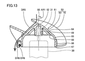
- FIG. 13 is a cross-sectional view showing a state when the propeller fan 50 is rotating.
- FIG. 14 is a diagram schematically illustrating a state when the boss portion 60 is rotating.
- propeller fan 50 receives rotational power from drive motor 30 (see FIG. 10) and rotates in the direction of arrow AR ⁇ b> 1, and from discharge port 15 (see FIG. 10) to discharge port 16 (see FIG. 10).
- An airflow (see arrow DR5) that flows toward (see FIG. 10) is generated.
- the airflow from the suction port 15 flows from the upstream side toward the downstream side along the blade surface of the blade portion 70 and the outer surface 61 of the boss portion 60.
- the air flowing through the space around the boss 60 where the wings 70 are not provided flows along the upstream surface 64 of the outer surface 61 on the upstream side.
- the air flowing through the space around the boss 60 where the wings 70 are not provided does not flow along the downstream surface 66 of the outer surface 61 on the downstream side, and the centrifugal force from the outer surface 61 does not flow. In response to the action, it peels from the outer surface 61 in the vicinity of the downstream end 65 of the upstream surface 64.
- the air flowing through the space around the boss portion 60 where the wing portion 70 is not provided flows on the outer side in the rotational radius direction than the outer surface 61 on the downstream side (see arrow DR5).
- a vortex as indicated by the arrow DR6 is generated between the air flow and the downstream surface 66 of the boss portion 60.
- This vortex is generated when a part of the vortex is separated from the air flowing in the direction of the arrow DR5 and the part of the separated air is subjected to the centrifugal force from the outer surface 61.
- Most of the vortex occurs at a position upstream of the downstream portion 67 of the boss portion 60. The vortex does not fold around the downstream portion 67 of the boss portion 60 and does not flow so as to be sucked into the boss portion 60 toward the inner surface 68 side.
- the bottom wall 44B of the motor support portion 44 and the output shaft 31 are in the direction parallel to the rotation shaft 80.
- the boss portion 60 is located upstream of the most downstream portion (downstream portion 67).
- the portion near the bottom wall 44 ⁇ / b> B of the motor support portion 44, the bottom wall 44 ⁇ / b> B and the output shaft 31 are arranged so as to be covered by the inner surface 68 of the boss portion 60. It is further suppressed that foreign matters such as hair are entangled with the output shaft 31.
- FIG. 15 is a diagram schematically showing a boss portion 60A in the first modification of the first embodiment.
- the outer surface 61 of the boss portion 60 ⁇ / b> A includes an upstream end portion 62, an upstream surface 64, a downstream end 65 of the upstream surface 64, a downstream surface 66, and a downstream portion 67.
- the upstream end 62 is formed at the most upstream (vertical) position of the outer surface 61.
- a rotating shaft 80 is formed so as to pass through the upstream end 62 when the propeller fan is rotating.
- the upstream surface 64 has a substantially conical surface shape continuous to the upstream end portion 62 and extends toward the outer side in the rotational radial direction of the propeller fan toward the downstream side.
- the downstream end 65 of the upstream surface 64 is formed at the most downstream position of the upstream surface 64.
- the downstream portion 67 is located further downstream than the downstream end 65 of the upstream surface 64.
- the downstream portion 67 of this modification is located on the most downstream side of the outer surface 61 as a whole.
- the downstream surface 66 of the boss portion 60 ⁇ / b> A is also formed so as to connect the downstream end 65 of the upstream surface 64 and the downstream portion 67.
- the downstream surface 66 of the present modification has a conical surface shape as a whole, and extends toward the downstream portion 67 so as to decrease in diameter toward the inner side in the rotational radius direction rather than in a direction parallel to the rotation shaft 80. ing.
- the external shape of the portion including the downstream surface 66 of the boss portion 60 ⁇ / b> A has a substantially truncated cone shape whose diameter decreases toward the downstream portion 67.
- the shape of the truncated cone is a solid shape that is not a cone among solids obtained by bisecting the cone by a plane parallel to the bottom surface.
- the shape of the substantially truncated cone referred to here does not only mean the shape of a surface whose side surface shape (the shape of the downstream surface 66) is a substantially straight line, but also the portion of the downstream surface 66 near the downstream end 65 and Or the case where the part near the downstream part 67 of the downstream surface 66 is curving suitably is included.
- the shape of the downstream surface 66 of the present modification may be formed so as to be curved as a whole as long as the downstream surface 66 extends toward the inner side in the rotational radial direction toward the downstream side.
- the shape in which 66 is curved toward the rotation axis and the shape in which the downstream surface 66 is curved away from the rotation axis are also included in the “substantially truncated cone shape”.
- a vortex as indicated by the arrow DR6 is generated between the air flow and the downstream surface 66 of the boss portion 60A. Most of the vortex is generated at a position upstream of the downstream portion 67 of the boss portion 60A. The vortex does not turn around the downstream portion 67 of the boss portion 60A and does not flow so as to be sucked into the boss portion 60A. Therefore, even when the boss portion 60A is used, the blowing efficiency is not lowered, and it is possible to effectively suppress the failure induced by foreign matters such as hair.
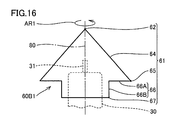
- FIG. 16 is a diagram schematically showing a boss 60B1 in the second modification of the first embodiment.
- the outer surface 61 of the boss portion 60B1 includes an upstream end portion 62, an upstream surface 64, a downstream end 65 of the upstream surface 64, a downstream surface 66, and a downstream portion 67.
- the upstream end 62 is formed at the most upstream (vertical) position of the outer surface 61.
- a rotating shaft 80 is formed so as to pass through the upstream end 62 when the propeller fan is rotating.
- the upstream surface 64 has a substantially conical surface shape continuous to the upstream end portion 62 and extends toward the outer side in the rotational radial direction of the propeller fan toward the downstream side.
- the downstream end 65 of the upstream surface 64 is formed at the most downstream position of the upstream surface 64.
- the downstream portion 67 is located further downstream than the downstream end 65 of the upstream surface 64.
- the downstream portion 67 of this modification is located on the most downstream side of the outer surface 61 as a whole.
- the downstream surface 66 of the boss portion 60B1 is also formed so as to connect the downstream end 65 and the downstream portion 67 of the upstream surface 64.
- the downstream surface 66 of this modification has a first downstream surface 66A and a second downstream surface 66B.
- the first downstream surface 66A extends in a direction orthogonal to the rotation shaft 80.
- the second downstream surface 66B has a cylindrical surface shape continuous with the first downstream surface 66A and extends in a direction parallel to the rotation shaft 80.
- the entire downstream surface 66 extends toward the downstream portion 67 while being bent toward the inner side in the rotational radial direction rather than in a direction parallel to the rotational axis 80.
- the air flowing in the space where the wing portion around the boss portion 60B1 is not provided flows along the upstream surface 64 of the outer surface 61 on the upstream side and outside on the downstream side. It does not flow along the downstream surface 66 of the surface 61 but peels from the outer surface 61 in the vicinity of the downstream end 65 of the upstream surface 64.
- the air flowing through the space around the boss 60 ⁇ / b> B ⁇ b> 1 where the wings are not provided flows on the outer side in the rotational radius direction than the outer surface 61 on the downstream side.
- a vortex is generated between the air flow and the downstream surface 66 of the boss 60B1. Most of the vortex is generated at a position upstream of the downstream portion 67 of the boss portion 60B1. The vortex does not turn around the downstream portion 67 of the boss portion 60B1, and does not flow so as to be sucked into the boss portion 60B1. Therefore, even when the boss portion 60B1 is used, it is possible to effectively suppress a failure induced by a foreign object such as hair without reducing the blowing efficiency.
- FIG. 17 is a diagram schematically showing a boss portion 60B2 in the third modification example of the first embodiment.
- the outer surface 61 of the boss portion 60B2 includes an upstream end portion 62, an upstream surface 64, a downstream end 65 of the upstream surface 64, a downstream surface 66, and a downstream portion 67.
- the upstream end 62 is formed at the most upstream (vertical) position of the outer surface 61.
- a rotating shaft 80 is formed so as to pass through the upstream end 62 when the propeller fan is rotating.
- the upstream surface 64 has a substantially hemispherical shape continuous to the upstream end portion 62, and extends so as to increase in diameter toward the outer side in the rotational radial direction of the propeller fan toward the downstream side.
- the downstream end 65 of the upstream surface 64 is formed at the most downstream position of the upstream surface 64.
- the downstream portion 67 is located further downstream than the downstream end 65 of the upstream surface 64.
- the downstream portion 67 of this modification is located on the most downstream side of the outer surface 61 as a whole.
- the downstream surface 66 of the boss portion 60B2 is also formed so as to connect the downstream end 65 of the upstream surface 64 and the downstream portion 67.
- the downstream surface 66 of the present modification has a substantially conical shape that is continuous with the downstream end 65 of the upstream surface 64, and as it goes toward the downstream portion 67, it is more in the radial direction of rotation than in the direction parallel to the rotational axis 80. It extends linearly so as to reduce its diameter toward the inside.
- the air flowing through the space around the boss portion 60B2 where the wing portion is not provided flows along the upstream surface 64 of the outer surface 61 on the upstream side and outside on the downstream side. It does not flow along the downstream surface 66 of the surface 61 but peels from the outer surface 61 in the vicinity of the downstream end 65 of the upstream surface 64.
- the air flowing through the space around the boss portion 60B2 where the wing portion is not provided flows outside the outer surface 61 in the rotational radius direction on the downstream side.
- a vortex is generated between the air flow and the downstream surface 66 of the boss 60B2. Most of the vortex is generated at a position upstream of the downstream portion 67 of the boss portion 60B2. The vortex does not fold around the downstream portion 67 of the boss portion 60B2, and does not flow so as to be sucked into the boss portion 60B2. Therefore, even when the boss portion 60B2 is used, the air blowing efficiency is not lowered, and it is possible to effectively suppress the failure induced by foreign matters such as hair.
- FIG. 18 is a diagram schematically showing a boss portion 60B3 in the fourth modification example of the first embodiment.
- the outer surface 61 of the boss portion 60B3 includes an upstream end portion 62, an upstream surface 64, a downstream end 65 of the upstream surface 64, a downstream surface 66, and a downstream portion 67.
- the upstream end 62 is formed at the most upstream (vertical) position of the outer surface 61.
- a rotating shaft 80 is formed so as to pass through the upstream end 62 when the propeller fan is rotating.
- the upstream surface 64 has a substantially hemispherical shape continuous to the upstream end portion 62, and extends so as to increase in diameter toward the outer side in the rotational radial direction of the propeller fan toward the downstream side.
- the downstream end 65 of the upstream surface 64 is formed at the most downstream position of the upstream surface 64.
- the downstream portion 67 is located further downstream than the downstream end 65 of the upstream surface 64.
- the downstream portion 67 of this modification is located on the most downstream side of the outer surface 61 as a whole.
- the downstream surface 66 of the boss portion 60B3 is also formed so as to connect the downstream end 65 of the upstream surface 64 and the downstream portion 67.
- the downstream surface 66 of this modification has a first downstream surface 66A and a second downstream surface 66B.
- the first downstream surface 66A extends in a direction orthogonal to the rotation shaft 80.
- the second downstream surface 66B has a cylindrical surface shape continuous with the first downstream surface 66A and extends in a direction parallel to the rotation shaft 80.
- the entire downstream surface 66 extends toward the downstream portion 67 while being bent toward the inner side in the rotational radial direction rather than in a direction parallel to the rotational axis 80.
- the air flowing through the space around the boss portion 60B3 where the wing portion is not provided flows along the upstream surface 64 of the outer surface 61 on the upstream side and outside on the downstream side. It does not flow along the downstream surface 66 of the surface 61 but peels from the outer surface 61 in the vicinity of the downstream end 65 of the upstream surface 64.
- the air flowing through the space around the boss portion 60B3 where the wing portion is not provided flows on the outer side in the rotational radius direction than the outer surface 61 on the downstream side.
- a vortex is generated between the air flow and the downstream surface 66 of the boss 60B3. Most of the vortex is generated at a position upstream of the downstream portion 67 of the boss portion 60B3. The vortex does not fold around the downstream portion 67 of the boss portion 60B3 and does not flow so as to be sucked into the boss portion 60B3. Therefore, even when the boss portion 60B3 is used, the blowing efficiency is not lowered, and it is possible to effectively suppress the failure induced by foreign matters such as hair.
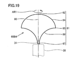
- FIG. 19 is a diagram schematically showing a boss portion 60B4 in the fifth modification example of the first embodiment.
- the outer surface 61 of the boss portion 60B4 includes an upstream end portion 62, an upstream surface 64, a downstream end 65 of the upstream surface 64, a downstream surface 66, and a downstream portion 67.
- the upstream end 62 is formed at the most upstream (vertical) position of the outer surface 61.
- a rotating shaft 80 is formed so as to pass through the upstream end 62 when the propeller fan is rotating.
- the upstream surface 64 has a substantially hemispherical shape continuous to the upstream end portion 62, and extends so as to increase in diameter toward the outer side in the rotational radial direction of the propeller fan toward the downstream side.
- the downstream end 65 of the upstream surface 64 is formed at the most downstream position of the upstream surface 64.
- the downstream portion 67 is located further downstream than the downstream end 65 of the upstream surface 64.
- the downstream portion 67 of this modification is located on the most downstream side of the outer surface 61 as a whole.
- the downstream surface 66 of the boss portion 60B4 is also formed so as to connect the downstream end 65 of the upstream surface 64 and the downstream portion 67.
- the downstream surface 66 of the present modification extends in an arc shape toward the inner side in the rotational radial direction rather than the direction parallel to the rotational axis 80 as it goes toward the downstream portion 67.
- the downstream surface 66 of this modification has an arcuate shape that is recessed inwardly toward the downstream portion 67.
- the air flowing through the space around the boss portion 60B4 where the wing portion is not provided flows along the upstream surface 64 of the outer surface 61 on the upstream side and outside on the downstream side. It does not flow along the downstream surface 66 of the surface 61 but peels from the outer surface 61 in the vicinity of the downstream end 65 of the upstream surface 64.
- the air flowing through the space around the boss portion 60B4 where the wing portion is not provided flows on the outer side in the rotational radius direction than the outer surface 61 on the downstream side.
- a vortex is generated between the air flow and the downstream surface 66 of the boss 60B4. Most of the vortex is generated at a position upstream of the downstream portion 67 of the boss portion 60B4. The vortex does not fold around the downstream portion 67 of the boss portion 60B4 and does not flow so as to be sucked into the boss portion 60B4. Therefore, even when the boss portion 60B4 is used, the blowing efficiency is not lowered, and it is possible to effectively suppress the failure induced by foreign matters such as hair.
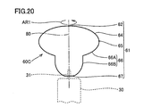
- FIG. 20 is a diagram schematically showing a boss portion 60C in the sixth modification example of the first embodiment.
- the outer surface 61 of the boss 60C includes an upstream end 62, an upstream surface 64, a downstream end 65 of the upstream surface 64, a downstream surface 66, and a downstream portion 67.
- the upstream end 62 is formed at the most upstream (vertical) position of the outer surface 61.
- a rotating shaft 80 is formed so as to pass through the upstream end 62 when the propeller fan is rotating.
- the upstream surface 64 has a substantially hemispherical shape continuous to the upstream end portion 62, and extends so as to increase in diameter toward the outer side in the rotational radial direction of the propeller fan toward the downstream side.
- the downstream end 65 of the upstream surface 64 is formed at the most downstream position of the upstream surface 64.
- the downstream portion 67 is located further downstream than the downstream end 65 of the upstream surface 64.
- the downstream portion 67 of this modification is located on the most downstream side of the outer surface 61 as a whole.
- the downstream surface 66 of the boss portion 60 ⁇ / b> C is also formed so as to connect the downstream end 65 of the upstream surface 64 and the downstream portion 67.
- the downstream surface 66 of this modification has a first downstream surface 66A and a second downstream surface 66B. 66 A of 1st downstream surfaces are extended in circular arc shape toward the inner side of a rotation radial direction rather than the direction parallel to the rotating shaft 80 as it goes downstream.
- the first downstream surface 66A of this modification has an arc shape that protrudes outward as it goes downstream.
- the second downstream surface 66B extends in a direction parallel to the rotation shaft 80 starting from the downstream end of the first downstream surface 66A, and further downstream of the second downstream surface 66B than the direction parallel to the rotation shaft 80. It extends in the shape of an arc toward the inside.
- the downstream portion of the second downstream surface 66B of this modification has an arcuate shape that protrudes outward as it goes downstream.
- the air flowing through the space where the wing portion around the boss portion 60C is not provided flows along the upstream surface 64 of the outer surface 61 on the upstream side and outside on the downstream side. It does not flow along the downstream surface 66 of the surface 61 but peels from the outer surface 61 in the vicinity of the downstream end 65 of the upstream surface 64.
- the air flowing in the space around the boss portion 60 ⁇ / b> C where the wing portion is not provided flows on the outer side in the rotational radius direction than the outer surface 61 on the downstream side.
- a vortex is generated between the air flow and the downstream surface 66 of the boss 60C. Most of the vortex is generated at a position upstream of the downstream portion 67 of the boss portion 60C. This vortex does not fold around the downstream portion 67 of the boss portion 60C and does not flow so as to be sucked into the boss portion 60C. Therefore, even when the boss portion 60C is used, it is possible to effectively suppress a failure induced by foreign matters such as hair without reducing the blowing efficiency.
- FIG. 21 is a diagram schematically showing a boss portion 60D1 in the seventh modification example of the first embodiment.
- the outer surface 61 of the boss 60D1 includes an upstream end 62, an outer edge 62T of the upstream end 62, an upstream surface 64, a downstream end 65 of the upstream surface 64, a downstream surface 66, and a downstream portion 67.
- the upstream end 62 is formed at the most upstream (vertical) position of the outer surface 61 and has a planar shape.
- a rotation shaft 80 is formed so as to pass through the center of the upstream end portion 62 when the propeller fan is rotating.
- the upstream surface 64 has a substantially conical shape continuous to the outer edge 62T of the upstream end portion 62, and extends so as to increase in diameter toward the outer side in the rotational radial direction of the propeller fan as it goes downstream.
- the downstream end 65 of the upstream surface 64 is formed at the most downstream position of the upstream surface 64.
- the downstream portion 67 is located further downstream than the downstream end 65 of the upstream surface 64.
- the downstream portion 67 of this modification is located on the most downstream side of the outer surface 61 as a whole.
- the downstream surface 66 of the boss portion 60D1 is also formed so as to connect the downstream end 65 and the downstream portion 67 of the upstream surface 64.
- the downstream surface 66 of this modification has a first downstream surface 66A and a second downstream surface 66B.
- the first downstream surface 66A extends in a direction orthogonal to the rotation shaft 80.
- the second downstream surface 66B has a cylindrical surface shape continuous with the first downstream surface 66A and extends in a direction parallel to the rotation shaft 80.
- the entire downstream surface 66 extends toward the downstream portion 67 while being bent toward the inner side in the rotational radial direction rather than in a direction parallel to the rotational axis 80.
- the air flowing through the space around the boss portion 60D1 where the wing portion is not provided flows along the upstream surface 64 of the outer surface 61 on the upstream side and outside on the downstream side. It does not flow along the downstream surface 66 of the surface 61 but peels from the outer surface 61 in the vicinity of the downstream end 65 of the upstream surface 64.
- the air flowing through the space around the boss portion 60D1 where the wing portion is not provided flows on the outer side in the rotational radius direction than the outer surface 61 on the downstream side.
- a vortex is generated between the air flow and the downstream surface 66 of the boss 60D1. Most of the vortex is generated at a position upstream of the downstream portion 67 of the boss portion 60D1. The vortex does not fold around the downstream portion 67 of the boss portion 60D1, and does not flow so as to be sucked into the boss portion 60D1. Therefore, even when the boss portion 60D1 is used, the blowing efficiency is not lowered, and it is possible to effectively suppress the failure induced by foreign matters such as hair.
- FIG. 22 is a diagram schematically showing a boss portion 60D2 in the eighth modification example of the first embodiment.
- the outer surface 61 of the boss portion 60D2 includes an upstream end portion 62, an outer edge 62T of the upstream end portion 62, an upstream surface 64, a downstream end 65 of the upstream surface 64, a downstream surface 66, and a downstream portion 67.
- the upstream end 62 is formed at the most upstream (vertical) position of the outer surface 61 and has a planar shape.
- a rotation shaft 80 is formed so as to pass through the center of the upstream end portion 62 when the propeller fan is rotating.
- the upstream surface 64 has a substantially conical shape continuous to the outer edge 62T of the upstream end portion 62, and extends so as to increase in diameter toward the outer side in the rotational radial direction of the propeller fan as it goes downstream.
- the downstream end 65 of the upstream surface 64 is formed at the most downstream position of the upstream surface 64.
- the downstream portion 67 is located further downstream than the downstream end 65 of the upstream surface 64.
- the downstream portion 67 of this modification is located on the most downstream side of the outer surface 61 as a whole.
- the downstream surface 66 of the boss portion 60D2 is also formed so as to connect the downstream end 65 of the upstream surface 64 and the downstream portion 67.
- the downstream surface 66 of the present modification extends in an arc shape toward the inner side in the rotational radial direction rather than the direction parallel to the rotation shaft 80 as it goes downstream.
- the downstream surface 66 of this modification has an arcuate shape that protrudes outward as it goes downstream.
- the air flowing through the space where the wing portion around the boss portion 60D2 is not provided flows along the upstream surface 64 of the outer surface 61 on the upstream side and outside on the downstream side. It does not flow along the downstream surface 66 of the surface 61 but peels from the outer surface 61 in the vicinity of the downstream end 65 of the upstream surface 64.
- the air flowing through the space around the boss portion 60D2 where the wing portion is not provided flows on the outer side in the radial direction of rotation than the outer surface 61 on the downstream side.
- a vortex is generated between the air flow and the downstream surface 66 of the boss 60D2. Most of the vortex is generated at a position upstream of the downstream portion 67 of the boss portion 60D2. The vortex does not fold around the downstream portion 67 of the boss portion 60D2, and does not flow so as to be sucked into the boss portion 60D2. Therefore, even when the boss portion 60D2 is used, the blowing efficiency is not lowered, and it is possible to effectively suppress the failure induced by foreign matters such as hair.
- FIG. 23 is a diagram schematically showing a boss portion 60D3 in the ninth modification example of the first embodiment.
- the outer surface 61 of the boss portion 60D3 includes an upstream end portion 62, an outer edge 62T of the upstream end portion 62, an upstream surface 64, a downstream end 65 of the upstream surface 64, a downstream surface 66, and a downstream portion 67.
- the upstream end 62 is formed at the most upstream (vertical) position of the outer surface 61 and has a planar shape.
- a rotation shaft 80 is formed so as to pass through the center of the upstream end portion 62 when the propeller fan is rotating.
- the upstream surface 64 has a substantially conical shape continuous to the outer edge 62T of the upstream end portion 62, and extends so as to increase in diameter toward the outer side in the rotational radial direction of the propeller fan as it goes downstream.
- the downstream end 65 of the upstream surface 64 is formed at the most downstream position of the upstream surface 64.
- the downstream portion 67 is located further downstream than the downstream end 65 of the upstream surface 64.
- the downstream portion 67 of this modification is located on the most downstream side of the outer surface 61 as a whole.
- the downstream surface 66 of the boss portion 60D3 is also formed so as to connect the downstream end 65 and the downstream portion 67 of the upstream surface 64.
- the downstream surface 66 of the present modification extends in an arc shape toward the inner side in the rotational radial direction rather than the direction parallel to the rotation shaft 80 as it goes downstream.
- the downstream surface 66 of this modification has an arcuate shape that becomes concave toward the downstream side.
- the air flowing through the space around the boss portion 60D3 where the wing portion is not provided flows along the upstream surface 64 of the outer surface 61 on the upstream side and outside on the downstream side. It does not flow along the downstream surface 66 of the surface 61 but peels from the outer surface 61 in the vicinity of the downstream end 65 of the upstream surface 64.
- the air flowing through the space around the boss portion 60D3 where the wing portion is not provided flows outside the outer surface 61 in the rotational radius direction on the downstream side.
- a vortex is generated between the air flow and the downstream surface 66 of the boss 60D3. Most of the vortex is generated at a position upstream of the downstream portion 67 of the boss portion 60D3. This vortex does not fold around the downstream portion 67 of the boss 60D3 and does not flow so as to be sucked into the boss 60D3. Therefore, even when the boss portion 60D3 is used, it is possible to effectively suppress a failure induced by a foreign object such as hair without reducing the blowing efficiency.
- FIG. 24 is a diagram schematically showing a boss portion 60E1 in the tenth modification example of the first embodiment.
- the outer surface 61 of the boss 60E1 includes an upstream end 62, an outer edge 62T of the upstream end 62, an upstream surface 64, a downstream end 65 of the upstream surface 64, a downstream surface 66, and a downstream portion 67.
- the upstream end 62 is formed at the most upstream (vertical) position of the outer surface 61 and has a planar shape.
- a rotation shaft 80 is formed so as to pass through the center of the upstream end portion 62 when the propeller fan is rotating.
- the upstream surface 64 has a substantially cylindrical surface shape continuous with the outer edge 62 ⁇ / b> T of the upstream end portion 62, and extends along a direction parallel to the rotation shaft 80.
- the downstream end 65 of the upstream surface 64 is formed at the most downstream position of the upstream surface 64.
- the downstream portion 67 is located further downstream than the downstream end 65 of the upstream surface 64.
- the downstream portion 67 of this modification is located on the most downstream side of the outer surface 61 as a whole.
- the downstream surface 66 of the boss portion 60E1 is also formed so as to connect the downstream end 65 of the upstream surface 64 and the downstream portion 67.
- the downstream surface 66 of the present modification has a substantially conical surface shape that is continuous with the downstream end 65 of the upstream surface 64, and the inner side in the rotational radial direction than the direction parallel to the rotational axis 80 as it goes downstream. It extends in a straight line so as to reduce its diameter.
- the air flowing through the space around the boss portion 60E1 where the wing portion is not provided flows along the upstream surface 64 of the outer surface 61 on the upstream side and outside on the downstream side. It does not flow along the downstream surface 66 of the surface 61 but peels from the outer surface 61 in the vicinity of the downstream end 65 of the upstream surface 64.
- the air flowing through the space around the boss portion 60E1 where the wing portion is not provided flows outside the outer surface 61 in the rotational radius direction on the downstream side.
- a vortex is generated between the air flow and the downstream surface 66 of the boss 60E1. Most of the vortex is generated at a position upstream of the downstream portion 67 of the boss portion 60E1. The vortex does not fold around the downstream portion 67 of the boss portion 60E1, and does not flow so as to be sucked into the boss portion 60E1. Therefore, even when the boss portion 60E1 is used, the blowing efficiency is not lowered, and it is possible to effectively suppress the failure induced by foreign matters such as hair.
- FIG. 25 is a diagram schematically showing a boss portion 60E2 in the eleventh modification example of the first embodiment.
- the outer surface 61 of the boss portion 60E2 includes an upstream end portion 62, an outer edge 62T of the upstream end portion 62, an upstream surface 64, a downstream end 65 of the upstream surface 64, a downstream surface 66, and a downstream portion 67.
- the upstream end 62 is formed at the most upstream (vertical) position of the outer surface 61 and has a planar shape.
- a rotation shaft 80 is formed so as to pass through the center of the upstream end portion 62 when the propeller fan is rotating.
- the upstream surface 64 has a substantially cylindrical surface shape continuous to the outer edge 62T of the upstream end portion 62, and extends along a direction parallel to the rotation axis 80 toward the downstream side.
- the downstream end 65 of the upstream surface 64 is formed at the most downstream position of the upstream surface 64.
- the downstream portion 67 is located further downstream than the downstream end 65 of the upstream surface 64.
- the downstream portion 67 of this modification is located on the most downstream side of the outer surface 61 as a whole.
- the downstream surface 66 of the boss portion 60E2 is also formed so as to connect the downstream end 65 and the downstream portion 67 of the upstream surface 64.
- the downstream surface 66 of this modification has a first downstream surface 66A and a second downstream surface 66B.
- the first downstream surface 66A extends in a direction orthogonal to the rotation shaft 80.
- the second downstream surface 66B has a substantially conical surface shape continuous with the first downstream surface 66A, and contracts inward in the rotational radial direction rather than in a direction parallel to the rotation shaft 80 toward the downstream side. It extends linearly so as to have a diameter. The entire downstream surface 66 extends toward the downstream portion 67 while being bent toward the inner side in the rotational radial direction rather than in a direction parallel to the rotational axis 80.
- the air flowing through the space where the wing portion around the boss portion 60E2 is not provided flows along the upstream surface 64 of the outer surface 61 on the upstream side and outside on the downstream side. It does not flow along the downstream surface 66 of the surface 61 but peels from the outer surface 61 in the vicinity of the downstream end 65 of the upstream surface 64.
- the air flowing through the space around the boss portion 60E2 where the wing portion is not provided flows outside the outer surface 61 in the rotational radius direction on the downstream side.
- a vortex is generated between the air flow and the downstream surface 66 of the boss 60E2. Most of the vortex is generated at a position upstream of the downstream portion 67 of the boss portion 60E2. The vortex does not fold around the downstream portion 67 of the boss portion 60E2, and does not flow so as to be sucked into the boss portion 60E2. Therefore, even when the boss portion 60E2 is used, the blowing efficiency is not lowered, and it is possible to effectively suppress a failure induced by foreign matters such as hair.
- FIG. 26 is a diagram schematically showing a boss portion 60E3 in the twelfth modification of the first embodiment.
- the outer surface 61 of the boss portion 60E3 includes an upstream end portion 62, an outer edge 62T of the upstream end portion 62, an upstream surface 64, a downstream end 65 of the upstream surface 64, a downstream surface 66, and a downstream portion 67.
- the upstream end 62 is formed at the most upstream (vertical) position of the outer surface 61 and has a planar shape.
- a rotation shaft 80 is formed so as to pass through the center of the upstream end portion 62 when the propeller fan is rotating.
- the upstream surface 64 has a substantially conical surface shape that is continuous with the outer edge 62T of the upstream end portion 62, and contracts inward in the rotational radial direction from the direction parallel to the rotation shaft 80 toward the downstream side. It extends linearly so as to have a diameter.
- the downstream end 65 of the upstream surface 64 is formed at the most downstream position of the upstream surface 64.
- the downstream portion 67 is located further downstream than the downstream end 65 of the upstream surface 64.
- the downstream portion 67 of this modification is located on the most downstream side of the outer surface 61 as a whole.
- the downstream surface 66 of the boss portion 60E3 is also formed so as to connect the downstream end 65 of the upstream surface 64 and the downstream portion 67.
- the downstream surface 66 of this modification has a first downstream surface 66A and a second downstream surface 66B.
- the first downstream surface 66A extends in a direction orthogonal to the rotation shaft 80.
- the second downstream surface 66B has a cylindrical surface shape continuous with the first downstream surface 66A and extends in a direction parallel to the rotation shaft 80.
- the entire downstream surface 66 extends toward the downstream portion 67 while being bent toward the inner side in the rotational radial direction rather than in a direction parallel to the rotational axis 80.
- the air flowing through the space around the boss portion 60E3 where the wing portion is not provided flows along the upstream surface 64 of the outer surface 61 on the upstream side and outside on the downstream side. It does not flow along the downstream surface 66 of the surface 61 but peels from the outer surface 61 in the vicinity of the downstream end 65 of the upstream surface 64.
- the air flowing through the space around the boss portion 60E3 where the wing portion is not provided flows on the outer side in the rotational radius direction than the outer surface 61 on the downstream side.
- a vortex is generated between the air flow and the downstream surface 66 of the boss 60E3. Most of the vortex is generated at a position upstream of the downstream portion 67 of the boss portion 60E3. The vortex does not turn around the downstream portion 67 of the boss portion 60E3 and does not flow so as to be sucked into the boss portion 60E3. Therefore, even when the boss portion 60E3 is used, it is possible to effectively suppress a failure induced by foreign matters such as hair without reducing the blowing efficiency.
- Boss portion 60F has substantially the same shape as boss portion 60 (see FIG. 14) in the first embodiment.
- the outer surface 61 of the boss 60F includes an upstream end 62, an upstream surface 64, a downstream end 65 of the upstream surface 64, a downstream surface 66, and a downstream portion 67.
- the upstream end 62 is formed at the most upstream (vertex) position of the outer surface 61.
- a rotating shaft 80 (not shown) is formed to pass through the upstream end 62 when the propeller fan is rotating.
- the upstream surface 64 has a substantially conical surface shape continuous to the upstream end portion 62 and extends toward the outer side in the rotational radial direction of the propeller fan toward the downstream side.
- the downstream end 65 of the upstream surface 64 is formed at the most downstream position of the upstream surface 64.
- the downstream portion 67 is located further downstream than the downstream end 65 of the upstream surface 64.
- the downstream portion 67 of this experimental example is located on the most downstream side of the outer surface 61 as a whole.
- the downstream surface 66 of the boss portion 60F is also formed so as to connect the downstream end 65 of the upstream surface 64 and the downstream portion 67.
- the downstream surface 66 of this experimental example has a cylindrical surface shape that is continuous with the downstream end 65 of the upstream surface 64, and extends in a direction parallel to the rotation axis 80.
- the upstream end 62 of the boss 60F has an inner angle ⁇ 1.
- the upstream surface 64 of the boss portion 60F has a height dimension H in a direction parallel to the rotation shaft 80 (not shown).
- the downstream surface 66 of the boss portion 60F has a height dimension h in a direction parallel to the rotation shaft 80 (not shown).
- the downstream surface 66 of the boss portion 60F has an outer diameter D1.
- the internal angle ⁇ 1 and the height dimension H were treated as variable values (see FIGS. 28 and 29).
- the height dimension h and the outer diameter D1 were treated as fixed values.
- the value of the height dimension h is 10 mm, and the value of the outer diameter D1 is 40 mm.
- the internal angle ⁇ 1 of the upstream end 62 was changed from 0 ° to 170 °, and the height dimension H of the upstream surface 64 was also changed accordingly.
- a propeller fan provided with a plurality of types of boss portions 60F having different inner angles ⁇ 1 was prepared, and the propeller fan was disposed in a cylindrical case together with a drive motor. While rotating the propeller fan, 1000 hairs were flowed from the upstream side toward the downstream side. For each propeller fan, the operation of running 1000 hairs was repeated 5 times, and the average value of the number of hairs wound around the output shaft of the drive motor was calculated.
- the line L1 in FIG. 28 shows the relationship between the internal angle ⁇ 1 and the number of hairs wound on the output shaft of the drive motor.
- the horizontal axis in FIG. 28 indicates the internal angle ⁇ 1 of the upstream end portion 62 of the boss portion 60F.
- shaft of FIG. 28 has shown the average value of the number of the hair wound in the output shaft of a drive motor. This average value is an average value when the operation of flowing 1000 hairs is repeated 5 times.
- the inner angle ⁇ 1 at the upstream end 62 of the boss 60F is preferably 50 ° or more.
- the line L2 in FIG. 29 shows the relationship between the value of h / (H + h) and the number of hairs caught on the output shaft of the drive motor.
- the horizontal axis in FIG. 29 indicates a value obtained by dividing the height dimension h of the downstream surface 66 by (height dimension H + height dimension h).
- This height dimension H is the height dimension H of the upstream surface 64 obtained when the internal angle ⁇ 1 of the upstream end portion 62 is changed from 0 ° to 170 °.
- the value of h / (H + h) is a ratio of the height dimension h of the downstream surface 66 occupying in the total height (H + h) of the boss portion 60F in a direction parallel to the rotation shaft 80 (not shown).
- shaft of FIG. 29 has shown the average value of the number of the hair wound in the output shaft of a drive motor. This average value is an average value when the operation of flowing 1000 hairs is repeated 5 times.
- the ratio of the height dimension h of the downstream surface 66 in the total height (H + h) of the boss portion 60F is preferably 1/5 or more.
- the entrainment of hair can be suppressed by securing the height dimension h of the downstream surface 66 to some extent. Even if the height dimension h of the downstream surface 66 is less than 1/5 of the total height, the inner angle ⁇ 1 has a certain value and the flow is separated from the outer surface 61. If it is, the entrainment of hair can be suppressed. Therefore, the feature of the internal angle ⁇ 1 and the feature of h / (H + h) may be applied independently to the boss portion 60F.
- Boss portion 60G has substantially the same shape as boss portion 60 (see FIG. 14) in the first embodiment.
- the outer surface 61 of the boss 60G includes an upstream end 62, an upstream surface 64, a downstream end 65 of the upstream surface 64, a downstream surface 66, and a downstream portion 67.
- the upstream end 62 is formed at the most upstream (vertex) position of the outer surface 61.
- a rotating shaft 80 (not shown) is formed to pass through the upstream end 62 when the propeller fan is rotating.
- the upstream surface 64 has a substantially conical surface shape continuous to the upstream end portion 62 and extends toward the outer side in the rotational radial direction of the propeller fan toward the downstream side.
- the downstream end 65 of the upstream surface 64 is formed at the most downstream position of the upstream surface 64.
- the downstream portion 67 is located further downstream than the downstream end 65 of the upstream surface 64.
- the downstream portion 67 of this experimental example is located on the most downstream side of the outer surface 61 as a whole.
- the downstream surface 66 of the boss portion 60G is also formed so as to connect the downstream end 65 and the downstream portion 67 of the upstream surface 64.
- the downstream surface 66 of this experimental example has a cylindrical surface shape that is continuous with the downstream end 65 of the upstream surface 64, and extends in a direction parallel to the rotation axis 80.
- the upstream end 62 of the boss 60G has an inner angle ⁇ 2.
- the upstream surface 64 of the boss portion 60G has a height dimension H in a direction parallel to the rotation shaft 80 (not shown).
- the downstream surface 66 of the boss 60G has a height dimension h in a direction parallel to the rotation shaft 80 (not shown).
- the downstream surface 66 of the boss 60G has an outer diameter D2.
- the value of the internal angle ⁇ 2 was set to three types of 150 °, 98 °, and 60 ° (see FIG. 31).
- the value of the outer diameter D2 is 40 mm (fixed value).
- the height dimension H is 5.36 mm.
- the value of the height dimension H is 17.39 mm.
- the value of the height dimension H is 34.64 mm.
- the height dimension h was treated as a variable value (see FIG. 31).
- a propeller fan provided with three types of boss portions 60G having an internal angle ⁇ 2 of 150 °, 98 °, and 60 ° was prepared, and the propeller fan was arranged in a cylindrical case together with a drive motor. While rotating the propeller fan, 1000 hairs were flowed from the upstream side toward the downstream side. For each propeller fan, the operation of running 1000 hairs was repeated 5 times, and the average value of the number of hairs wound around the output shaft of the drive motor was calculated.
- the line L3 in FIG. 31 shows the relationship between the value of h / (H + h) and the number of hairs caught on the output shaft of the drive motor when the value of the internal angle ⁇ 2 is 150 °.
- a line L4 in FIG. 31 shows the relationship between the value of h / (H + h) and the number of hairs caught on the output shaft of the drive motor when the value of the internal angle ⁇ 2 is 98 °.
- a line L5 in FIG. 31 indicates the relationship between the value of h / (H + h) and the number of hairs caught on the output shaft of the drive motor when the value of the internal angle ⁇ 2 is 60 °.
- shaft of FIG. 31 has shown the average value of the number of the hair wound in the output shaft of a drive motor. This average value is an average value when the operation of flowing 1000 hairs is repeated 5 times.
- the ratio of the height dimension h of the downstream surface 66 occupying in the total height (H + h) of the boss 60G is preferably 1/5 or more.
- FIG. 32 shows the relationship between the value of the internal angle ⁇ 2 when the average value of the number of entangled hairs is two and the value of h / (H + h) when the average value of the number of entangled hairs is two. It is a figure. As shown in FIG. 32, the value of the internal angle ⁇ 2 when the average value of the number of entangled hairs is 2, and the value of h / (H + h) when the average value of the number of entangled hairs is two. It can be seen that changes substantially linearly.
- the ratio of the height dimension h of the downstream surface 66 occupying in the total height (H + h) of the boss portion 60G is preferably 1/5 or more, and it is desired to further suppress the entrainment of hair on the output shaft of the drive motor.
- Propeller fan 50Z1 includes a boss portion 60Z1 and a wing portion 70Z1.
- Propeller fan 50Z1 has substantially the same shape as propeller fan 50Z (see FIGS. 3 and 5) in Comparative Example 1 described above.
- the wing part 70Z1 of the propeller fan 50Z1 has a height dimension haz and a height dimension hbz.
- the height dimension haz is a position on the most downstream side in the wing part 70Z1 (a position of the rear edge part 74 in the wing part 70Z1) and a position of the root 72H of the front edge part 72 in the direction parallel to the rotation axis 80. It is a dimension between.
- the height dimension hbz is a dimension between the position on the most downstream side in the blade part 70Z1 and the position of the blade tip part 71 in the direction parallel to the rotation shaft 80.
- the front edge portion 72 of the present comparative example extends substantially along the direction perpendicular to the rotation shaft 80 of the propeller fan 50Z1.
- the value of hbz / haz is 1.05.
- FIG. 34 is a cross-sectional view showing a state when the propeller fan 50Z1 is rotating.
- Propeller fan 50Z1 receives the rotational power from drive motor 30 and rotates in the direction of arrow AR1, and generates an air flow (see arrow DR1) flowing from suction port 15 toward discharge port 16. As indicated by the arrow DR1, the airflow from the suction port 15 flows from the upstream side to the downstream side along the blade surface of the blade portion 70Z1 and the outer surface 61 of the boss portion 60Z1.
- a blade tip vortex is generated near the blade tip 71 of the blade 70Z1 as the blade 70Z1 rotates (see arrow DR3).
- the blade tip vortex is generated so as to extend toward the rear side in the rotation direction (arrow AR1 direction) with the vicinity of the blade tip 71 as a tip.
- the position of the blade tip part 71 of the blade part 70Z1 is close to the position of the downstream end (rear edge part 74) of the blade part 70Z1 (compared to the case of Embodiment 2 described later). Therefore, in propeller fan 50Z1, between the generation position of the blade tip vortex indicated by arrow DR3 and the generation position of the vortex generated near the downstream end (rear edge portion 74) of blade 70Z1 indicated by arrow DR2. The distance is getting shorter.
- the width W10 of the air passage through which air from the suction port 15 can smoothly flow toward the discharge port 16 is narrow, and the incident angle ⁇ 10 of air with respect to the inner wall surface of the inner case 12 is also increased.
- the incident angle ⁇ 10 referred to here is an angle formed between the direction of air flow and the inner wall surface of the inner case 12 when the air from the suction port 15 contacts the inner wall surface of the inner case 12. It is.
- propeller fan 50H Propeller fan 50H
- Propeller fan 50H includes boss portion 60H and wing portion 70H.
- Propeller fan 50H has substantially the same shape as propeller fan 50 (see FIG. 11) in the first embodiment.
- the blade portion 70H of the propeller fan 50H has a height dimension ha and a height dimension hb.
- the height ha is the position of the most downstream side of the wing 70H (the root of the trailing edge 74 in the wing 70H) and the position of the root 72H of the leading edge 72 in the direction parallel to the rotation axis 80. It is a dimension between.
- the height dimension hb is a dimension between the position on the most downstream side in the blade part 70 ⁇ / b> H and the position of the blade tip part 71 in the direction parallel to the rotation shaft 80.
- the front edge portion 72 extends from the front end portion in the rotational direction of the root portion 73 to the upstream side in the airflow direction from the outer surface 61 of the boss portion 60 toward the outer side in the rotational radial direction.
- the value of hb / ha is 2.20.
- FIG. 36 is a cross-sectional view showing a state when the propeller fan 50H is rotating.
- Propeller fan 50H receives rotational power from drive motor 30 and rotates in the direction of arrow AR1, and generates an airflow (see arrow DR1) that flows from suction port 15 toward discharge port 16. As indicated by the arrow DR1, the airflow from the suction port 15 flows from the upstream side toward the downstream side along the blade surface of the blade portion 70H and the outer surface 61 of the boss portion 60H.
- the blade tip vortex is generated in the vicinity of the blade tip 71 of the blade 70H as the blade 70H rotates (see arrow DR3).
- the blade tip vortex is generated so as to extend toward the rear side in the rotation direction (arrow AR1 direction) with the vicinity of the blade tip 71 as a tip.
- the position of the blade tip 71 of the blade 70H is far from the position of the downstream end of the blade 70H. Accordingly, in propeller fan 50H, the blade tip vortex generation position indicated by arrow DR3 and the vortex generation position generated near the downstream end (rear edge portion 74) of blade part 70H indicated by arrow DR6 are between. The distance is getting longer.
- the width W11 of the air passage through which the air from the suction port 15 can smoothly flow toward the discharge port 16 is wider than the width W10 (see FIG. 34), and the inner case 12
- the incident angle ⁇ 11 of air with respect to the inner wall surface is also smaller than the incident angle ⁇ 10 (see FIG. 34).
- the incident angle ⁇ 11 referred to here is an angle formed between the air flowing direction and the inner wall surface of the inner case 12 when the air from the suction port 15 contacts the inner wall surface of the inner case 12. It is.
- the line L10 in FIG. 37 shows the relationship between the value of hb / ha and the number of hairs caught on the output shaft of the drive motor.
- the horizontal axis in FIG. 37 indicates the value of hb / ha of the boss portion 60H.
- shaft of FIG. 37 has shown the average value of the number of the hair wound in the output shaft of a drive motor. This average value is an average value when the operation of flowing 1000 hairs is repeated 5 times.
- the value of hb / ha of the boss 60H is preferably 1.5 or more.
- a plurality of types of propeller fans having different values of the minimum clearance CL were prepared, and the propeller fans were arranged in a cylindrical case together with a drive motor. While rotating the propeller fan, 1000 hairs were flowed from the upstream side toward the downstream side. For each propeller fan, the operation of running 1000 hairs was repeated 5 times, and the average value of the number of hairs wound around the output shaft of the drive motor was calculated. On the other hand, the air volume was also measured on the downstream side of the cylindrical case while rotating the propeller fan.
- a line L20 in FIG. 39 shows the relationship between the value of the minimum gap CL and the number of hairs caught on the output shaft of the drive motor.
- a line L21 in FIG. 39 shows the relationship between the value of the minimum gap CL and the air volume measured on the downstream side of the cylindrical case. Referring to line L20 and line L21, it can be seen that when the value of the minimum gap CL is larger than about 3 mm, the air volume at the same rotation speed decreases and the number of hairs involved increases. It can be seen that when the value of the minimum clearance CL is 3 mm or less (for example, 2.27 mm), the air volume at the same rotation speed does not decrease, and the number of hairs can be further suppressed.
- FIG. 40 is a plan view showing propeller fan 50Z2 of Comparative Example 3 relating to the above-described Embodiment 2 (see FIG. 35).
- Propeller fan 50Z2 includes boss portion 60Z2 and wing portion 70Z2.
- Propeller fan 50Z2 has substantially the same shape as propeller fan 50Z (see FIG. 4) in Comparative Example 1 described above.
- the blade tip 71 and the blade trailing end 75 of this comparative example are located on substantially the same circle C10.
- the outer peripheral edge portion 76 extends in an arc shape along the rotation direction of the wing portion 70Z2 (the circumferential direction around the rotation shaft 80).
- propeller fan 50Z2 is viewed from a direction parallel to rotation axis 80 (in other words, when propeller fan 50Z2 is viewed in plan)
- the dimension between the rotating shaft 80 (upstream end part 62) and the blade rear-end part 75 is the same value.
- the blade tip 71 of the blade 70Z2 When the propeller fan 50Z2 is stationary, the blade tip 71 of the blade 70Z2 is located on the circle C10. On the other hand, when the propeller fan 50Z2 is rotating, a large moment (inertial force) acts on the blade surface on the blade tip portion 71 side of the blade portion 70Z2. The blade surface on the blade tip portion 71 side of the blade portion 70Z2 is elastically deformed so as to spread outward in the rotational radius direction. When propeller fan 50Z2 is formed of a resin molded product, the amount of elastic deformation is further increased. In order to prevent the blade tip 71 from interfering with the inner wall of the inner case 12, it is necessary to increase the inner diameter of the inner case 12.
- FIG. 41 is a plan view showing propeller fan 50J in the first modification of the above-described second embodiment (see FIG. 35).
- Propeller fan 50J includes boss portion 60J and wing portion 70J.
- the value of hb / ha of the boss 60H is preferably 1.5 or more. According to the said structure, the entrainment of hair hardly arises.
- the value of hb / ha is increased, the amount of elastic deformation of the blade surface of the wing portion also increases when the propeller fan is rotating.
- the outer peripheral edge 76 of the propeller fan 50J in the present modification has a shape extending from the outer side to the inner side in the rotational radius direction toward the blade tip 71.
- the dimension between rotating shaft 80 (upstream end 62) and blade tip 71 is determined.
- R1 is a value smaller than the dimension R2 between the rotating shaft 80 (upstream end portion 62) and the blade trailing end portion 75.
- blade tip 71 of blade portion 70J is not located on circle C10, but is located on the inner side in the radial direction of rotation than circle C10 (see FIG. 42). 42).
- a large moment acts on the blade surface on the blade tip 71 side of the blade 70J.
- the blade surface on the blade tip portion 71 side of the blade portion 70J is elastically deformed so as to spread outward in the rotational radius direction (see arrow DR10).
- propeller fan 50J is formed of a resin molded product, the amount of elastic deformation is further increased.
- the blade tip 71 is previously positioned inside in the rotational radius direction. Even if the blade surface on the blade tip portion 71 side of the blade portion 70J is elastically deformed so as to spread outward in the rotational radius direction, interference with the inner wall of the inner case 12 is suppressed.
- the blade portion of the propeller fan 50J is rotated so that the portion of the outer peripheral edge portion 76 near the blade tip portion 71 rotates substantially along the circumferential direction (circle C10).
- 70J may be designed in advance. According to this configuration, high air blowing efficiency can be obtained in a range where the wing portion 70J does not interfere with the inner wall of the inner case 12.
- FIG. 43 is a cross-sectional view partially showing the blower device in the second modified example of the above-described second embodiment (see FIGS. 35 and 36).
- the air blower of the present modification includes an inner case 12A (air path forming member).
- Inner case 12A has inner wall part 12A1, and recessed part 12W provided so that it might be dented from inner wall part 12A1 toward the outside of the rotation radius direction of propeller fan 50J.
- the recess 12W has an annular shape, and the air path in the inner case 12A is wide at the recess 12W and narrow at the inner wall 12A1.
- the most downstream portion 12W1 of the recess 12W is located upstream of the most downstream portion of the boss portion 60J (the downstream portion 67 in the boss portion 60J).
- the position of the downstream portion 67 of the boss portion 60J in the direction parallel to the rotation shaft 80 is indicated using a line LL1.
- an extension line LL2 is obtained by virtually extending a tangent formed at a portion near the blade tip 71 of the blade surface of the blade portion 70J toward the outside in the rotational radial direction.
- the most downstream portion 12W1 of the recess 12W is located on the downstream side (the discharge port 16 side) from the extension line LL2.
- the most upstream portion 12W2 of the recess 12W is located upstream (on the suction port 15 side) of the extension line LL2.
- a blade tip vortex is generated near the blade tip 71 of the blade 70J (see arrow DR3).
- the blade tip vortex is generated so as to extend toward the rear side in the rotation direction (arrow AR1 direction) with the vicinity of the blade tip 71 as a tip.
- the blade tip vortex enters the recess 12W by the action of centrifugal force, and the recess 12W is provided in the inner case 12. It occurs at a portion closer to the recess 12W than when not.
- the distance between them is longer than that in the case of the above-described comparative example 2 (see FIG. 34).
- the width of the air passage through which air from the suction port 15 can smoothly flow toward the discharge port 16 is wider than the width W10 (see FIG. 34) of the second comparative example, and the air flow to the inner wall surface of the inner case 12A is large.
- the incident angle is also smaller than the incident angle ⁇ 10 (see FIG. 34) of Comparative Example 2.
- the most downstream portion 12W1 of the recess 12W is located upstream of the most downstream portion of the boss portion 60J (the downstream portion 67 in the boss portion 60J), and is the most of the recess 12W.
- the downstream portion 12W1 is located on the downstream side (the discharge port 16 side) of the extension line LL2, and the most upstream portion 12W2 of the recess 12W is located on the upstream side (the suction port 15 side) of the extension line LL2. is doing.
- the inner case 12A of the present modification may be configured as follows.
- the most downstream portion 12W1 of the recess 12W is located upstream of the most downstream portion of the boss portion 60J (the downstream portion 67 in the boss portion 60J). Further, the most downstream portion 12W1 of the recess 12W is located on the downstream side (discharge port 16 side) of the blade tip portion 71 of the blade portion 70J of the propeller fan 50J, and the most upstream portion 12W2 of the recess 12W is the propeller.
- the inner case 12A of the present modification may be configured so as to be located upstream of the blade tip portion 71 of the blade portion 70J of the fan 50J (on the suction port 15 side).
- FIG. 44 is a cross-sectional view partially showing the blower device in the third modified example of the above-described second embodiment (see FIGS. 35 and 36).
- the air blower of this modification is provided with the inner case 12B (air path forming member).
- the inner case 12B has a first inner wall portion 12B1 and a second inner wall portion 12B2.
- the second inner wall portion 12B2 is located on the downstream side (discharge port 16 side) with respect to the first inner wall portion 12B1, and has a narrower air passage area than the first inner wall portion 12B1.
- a step is formed between the first inner wall portion 12B1 and the second inner wall portion 12B2, and the air passage in the inner case 12B is wide in the first inner wall portion 12B1 and narrowed in the second inner wall portion 12B2.
- the most upstream portion 12BB of the second inner wall portion 12B2 is located upstream of the most downstream portion of the boss portion 60J (the downstream portion 67 in the boss portion 60J). To do.
- the position of the downstream portion 67 of the boss portion 60J in the direction parallel to the rotation shaft 80 is indicated using a line LL1.
- an extension line LL2 is obtained by virtually extending a tangent formed at a portion near the blade tip 71 of the blade surface of the blade portion 70J toward the outside in the rotational radial direction.
- the most upstream portion 12BB of the second inner wall portion 12B2 is located on the downstream side (discharge port 16 side) with respect to the extension line LL2. ing.
- a blade tip vortex is generated near the blade tip 71 of the blade 70J (see arrow DR3).
- the blade tip vortex is generated so as to extend toward the rear side in the rotation direction (arrow AR1 direction) with the vicinity of the blade tip 71 as a tip.
- the blade tip vortex is caused by the action of centrifugal force. It enters into the step between the first inner wall portion 12B1 and the second inner wall portion 12B2, and occurs at a portion closer to the first inner wall portion 12B1 than when the inner case 12 is not provided with a step.
- the distance between them is longer than that in the case of the above-described comparative example 2 (see FIG. 34).
- the width of the air path through which air from the suction port 15 can smoothly flow toward the discharge port 16 is wider than the width W10 (see FIG. 34) of the second comparative example, and the air flow with respect to the inner wall surface of the inner case 12B.
- the incident angle is also smaller than the incident angle ⁇ 10 (see FIG. 34) of Comparative Example 2.
- the most upstream portion 12BB of the second inner wall portion 12B2 is located upstream of the most downstream portion of the boss portion 60J (the downstream portion 67 in the boss portion 60J), Further, the most upstream portion 12BB of the second inner wall portion 12B2 is located on the downstream side (the discharge port 16 side) of the extension line LL2.
- the inner case 12B of the present modification may be configured as follows.
- the most upstream portion 12BB of the second inner wall portion 12B2 is upstream of the most downstream portion of the boss portion 60J (the downstream portion 67 in the boss portion 60J). And the most upstream portion 12BB of the second inner wall portion 12B2 is located on the downstream side (discharge port 16 side) of the blade tip portion 71 of the blade portion 70J of the propeller fan 50J.
- the inner case 12B may be configured.
- FIG. 45 is a plan view showing propeller fan 50K and rectifying blade 40K in the present embodiment.
- FIG. 45 shows a state where the bearing 69 of the propeller fan 50K is attached to the output shaft 31 of the drive motor 30 (not shown).
- FIG. 46 is a plan view showing a state when the propeller fan 50K is attached to the drive motor 30 (not shown).
- 47 is an enlarged plan view showing a region surrounded by the XKVII line in FIG.
- propeller fan 50K 45 to 47
- propeller fan 50K includes boss portion 60K and wing portion 70K, and has substantially the same shape as propeller fan 50 (see FIG. 12) in the first embodiment described above.
- Propeller fan 50K is attached to output shaft 31 of the drive motor as shown by arrow DR50 in FIG.
- reference line LA is virtually obtained by connecting the innermost portion 79 of the trailing edge portion 74 of the blade portion 70K and the rotation shaft 80 (upstream end portion 62) in the rotational radius direction of the propeller fan 50K.
- Straight line is virtually obtained by connecting the innermost portion 79 of the trailing edge portion 74 of the blade portion 70K and the rotation shaft 80 (upstream end portion 62) in the rotational radius direction of the propeller fan 50K.
- the imaginary straight line LB includes the innermost portion 79 of the trailing edge 74 of the blade portion 70K in the rotational radius direction of the propeller fan 50K and the trailing edge portion 74 of the blade portion 70K in the rotational radius direction of the propeller fan 50K. It is a straight line obtained virtually by connecting the outermost part (blade trailing end 75). An angle ⁇ A is formed between the reference line LA and the virtual straight line LB.
- the plate-like portion 42 of the rectifying blade 40 ⁇ / b> K extends radially outward from the outer surface of the motor support portion 44.
- the five plate-like portions 42 are arranged at intervals in the circumferential direction so as not to reduce the flow rate of the airflow flowing from the suction port toward the discharge port.
- the plate-like portion 42 has an upstream edge portion 43 on the upstream side.
- the upstream edge 43 in the present embodiment has a planar shape and extends along a direction perpendicular to the rotation shaft 80 (not shown) of the propeller fan 50K.
- the reference line LC and A virtual straight line LD (fourth virtual straight line) is formed.
- the reference line LC is virtually obtained by connecting the innermost portion 47 of the upstream edge 43 of the rectifying blade 40K and the rotary shaft 80 (output shaft 31) in the rotational radius direction of the propeller fan 50K. It is a straight line.
- the virtual straight line LD has an innermost portion 47 of the upstream edge 43 of the rectifying blade 40K in the rotational radius direction of the propeller fan 50K, and an upstream edge 43 of the rectifying blade 40K in the rotational radius direction of the propeller fan 50K. It is a straight line obtained virtually by connecting the outermost portion 48 of them. An angle ⁇ B is formed between the reference line LC and the virtual straight line LD.
- the value of angle ⁇ A is 43 ° and the value of angle ⁇ B is ⁇ 13 °.
- the angles ⁇ A and ⁇ B are positive values.
- the angles ⁇ A and ⁇ B have negative values.
- the angle difference ⁇ C 0 °.
- the imaginary straight line LB formed along the trailing edge 74 of the wing part 70K and the imaginary straight line LD formed along the upstream edge part 43 of the rectifying blade 40K extend in the same direction.
- the trailing edge portion 74 of the wing portion 70K and the upstream edge portion 43 of the rectifying blade 40K overlap almost or completely.
- FIG. 48 is a diagram showing the relationship between the angle difference ⁇ C obtained at that time and the noise.
- the angle difference ⁇ C is a difference between the angle ⁇ A and the angle ⁇ B.
- the value of the angle difference ⁇ C was changed from 0 ° to 120 ° by changing the value of the angle ⁇ B (see FIG. 47).
- a line L30 in FIG. 48 indicates that the virtual straight line LD formed at the upstream edge 43 of the rectifying blade 40K is directed to the rear side in the rotational direction from the virtual straight line LB formed at the rear edge 74 of the blade 70K.
- the relationship between the angle difference ⁇ C and the noise in the case of being present (case as shown in FIG. 47) is shown.
- a line L31 in FIG. 48 indicates that the virtual straight line LD formed at the upstream edge portion 43 of the rectifying blade 40K is more forward than the virtual straight line LB formed at the rear edge portion 74 of the blade portion 70K.
- the relationship between the angle difference ⁇ C and the noise in the case of being present is shown.
- the noise sharply decreases as the value of the angle difference ⁇ C is increased from 0 °. It can be seen that when the value of the angle difference ⁇ C is 10 ° or more and 90 ° or less, the generation of noise is greatly suppressed. Therefore, the value of the angle difference ⁇ C, in other words, the angle formed between the virtual straight line LD formed at the upstream edge 43 of the rectifying blade 40K and the virtual straight line LB formed at the trailing edge 74 of the blade 70K is 10 °. It can be seen that the angle is preferably 90 ° or less.
- FIG. 49 is a plan view schematically showing propeller fan 50L1 and rectifying blade 40L1 in the first modification of the third embodiment.
- Propeller fan 50L1 has boss portion 60L1 and wing portion 70L1.
- the trailing edge portion 74 of the wing portion 70L1 has a substantially linear shape.
- a virtual straight line LB is formed on the trailing edge portion 74 of the wing portion 70L1 as in the third embodiment.
- the upstream edge 43 of the straightening blade 40L1 extends along the rotational radius direction.
- a virtual straight line LD is formed at the upstream edge 43 of the rectifying blade 40L1 as in the third embodiment.
- the upstream edge 43 (virtual straight line LD) of the rectifying blade 40L1 extends toward the rear side in the rotational direction from the rear edge 74 (virtual straight line LB) of the blade 70L1.
- the value of the angle difference ⁇ C in other words, the virtual straight line LD formed on the upstream edge 43 of the rectifying blade 40L1 and the virtual straight line LB formed on the trailing edge 74 of the blade 70L1 is formed.
- the angle is 10 ° or more and 90 ° or less, the air current can flow smoothly toward the downstream side, so that a so-called peak sound is hardly generated, and as a result, the noise generated from the propeller fan 50L1 is effectively suppressed. It becomes possible to do.
- FIG. 50 is a plan view schematically showing propeller fan 50L2 and rectifying blade 40L2 in the second modification of the third embodiment.
- Propeller fan 50L2 has boss portion 60L2 and wing portion 70L2.
- the rear edge portion 74 of the wing portion 70L2 has a substantially linear shape, and extends toward the front side in the rotational direction toward the outer peripheral side (the inner case 12 side).
- a virtual straight line LB is formed at the trailing edge portion 74 of the wing portion 70L2 as in the third embodiment.
- the upstream edge portion 43 of the rectifying blade 40L2 When the rectifying blade 40L2 is viewed in plan, the upstream edge portion 43 of the rectifying blade 40L2 has a substantially linear shape, and extends toward the rear side in the rotation direction toward the outer peripheral side (the inner case 12 side). .
- a virtual straight line LD is formed at the upstream edge 43 of the rectifying blade 40L2 as in the third embodiment.
- the upstream edge 43 (virtual straight line LD) of the rectifying blade 40L2 extends toward the rear side in the rotational direction from the rear edge 74 (virtual straight line LB) of the blade 70L2.
- the value of the angle difference ⁇ C in other words, the virtual straight line LD formed on the upstream edge 43 of the rectifying blade 40L2 and the virtual straight line LB formed on the trailing edge 74 of the blade 70L2 is formed.
- the angle is 10 ° or more and 90 ° or less, the air current can flow smoothly toward the downstream side, so that a so-called peak sound is hardly generated, and as a result, the noise generated from the propeller fan 50L2 is effectively suppressed. It becomes possible to do.
- FIG. 51 is a plan view schematically showing propeller fan 50L3 and rectifying blade 40L3 in the third modification of the third embodiment.
- Propeller fan 50L3 has boss portion 60L3 and wing portion 70L3.
- the rear edge portion 74 of the wing portion 70L3 has a substantially linear shape and extends along the rotational radius direction.
- a virtual straight line LB is formed on the trailing edge 74 of the wing 70L3, as in the third embodiment.
- the upstream edge 43 of the flow straightening blade 40L3 When the flow straightening blade 40L3 is viewed in plan, the upstream edge 43 of the flow straightening blade 40L3 has an arc shape and extends toward the rear side in the rotation direction toward the outer peripheral side (the inner case 12 side).
- a virtual straight line LD is formed at the upstream edge 43 of the rectifying blade 40L3, as in the third embodiment.
- the upstream edge 43 (virtual straight line LD) of the rectifying blade 40L3 extends toward the rear side in the rotational direction from the rear edge 74 (virtual straight line LB) of the blade 70L3.
- the value of the angle difference ⁇ C in other words, the virtual straight line LD formed at the upstream edge 43 of the rectifying blade 40L3 and the virtual straight line LB formed at the trailing edge 74 of the blade 70L3.
- the angle is 10 ° or more and 90 ° or less, the air current can flow smoothly toward the downstream side, so that a so-called peak sound is hardly generated, and as a result, the noise generated from the propeller fan 50L3 is effectively suppressed. It becomes possible to do.
- FIG. 52 is a plan view schematically showing propeller fan 50L4 and rectifying blade 40L4 in the fourth modified example of the third embodiment.
- Propeller fan 50L4 has boss portion 60L4 and wing portion 70L4.
- the trailing edge portion 74 of the wing portion 70L4 has a curved shape, and a part in the rotational radius direction is formed to be recessed forward in the rotational direction.
- a virtual straight line LB is formed on the trailing edge 74 of the wing 70L4, as in the third embodiment.
- the upstream edge 43 of the straightening blade 40L4 When the straightening blade 40L4 is viewed in plan, the upstream edge 43 of the straightening blade 40L4 has a linear shape, and extends toward the rear side in the rotational direction toward the outer peripheral side (the inner case 12 side).
- a virtual straight line LD is formed at the upstream edge 43 of the rectifying blade 40L4, as in the third embodiment.
- the upstream edge 43 (virtual straight line LD) of the rectifying blade 40L4 extends toward the rear side in the rotational direction from the rear edge 74 (virtual straight line LB) of the blade 70L4.
- the value of the angle difference ⁇ C in other words, the virtual straight line LD formed at the upstream edge 43 of the rectifying blade 40L4 and the virtual straight line LB formed at the trailing edge 74 of the blade 70L4.
- the angle is 10 ° or more and 90 ° or less, the air current can flow smoothly toward the downstream side, so that a so-called peak sound is hardly generated, and as a result, the noise generated from the propeller fan 50L4 is effectively suppressed. It becomes possible to do.
- FIG. 53 is a plan view schematically showing propeller fan 50L5 and rectifying blade 40L5 in the fifth modification of the third embodiment.
- Propeller fan 50L5 has boss portion 60L5 and wing portion 70L5.
- the trailing edge portion 74 of the wing portion 70L5 has a linear shape and extends along the rotational radius direction.
- a virtual straight line LB is formed on the trailing edge portion 74 of the wing portion 70L5, as in the third embodiment.
- the upstream edge 43 of the rectifying blade 40L5 When the rectifying blade 40L5 is viewed in plan, the upstream edge 43 of the rectifying blade 40L5 has a curved shape and extends toward the front side in the rotational direction toward the outer peripheral side (the inner case 12 side).
- a virtual straight line LD is formed at the upstream edge 43 of the rectifying blade 40L5, as in the third embodiment.
- the upstream edge 43 (virtual straight line LD) of the rectifying blade 40L5 extends toward the front side in the rotational direction from the rear edge 74 (virtual straight line LB) of the blade 70L5.
- the value of the angle difference ⁇ C in other words, the virtual straight line LD formed on the upstream edge 43 of the rectifying blade 40L5 and the virtual straight line LB formed on the trailing edge 74 of the blade 70L5 is formed.
- the angle is not less than 10 ° and not more than 90 °, noise generated from the propeller fan 50L5 can be effectively suppressed.
- FIG. 54 is a plan view schematically showing propeller fan 50L6 and rectifying blade 40L6 in the sixth modification of the third embodiment.
- Propeller fan 50L6 has boss portion 60L6 and wing portion 70L6.
- the rear edge portion 74 of the wing portion 70L6 has a linear shape and extends along the rotational radius direction.
- a virtual straight line LB is formed on the trailing edge 74 of the wing 70L6, as in the third embodiment.
- the upstream edge 43 of the rectifying blade 40L6 When the rectifying blade 40L6 is viewed in plan, the upstream edge 43 of the rectifying blade 40L6 has a linear shape and extends toward the front side in the rotational direction toward the outer peripheral side (the inner case 12 side).
- a virtual straight line LD is formed at the upstream edge 43 of the rectifying blade 40L6, as in the third embodiment.
- the upstream edge 43 (virtual straight line LD) of the rectifying blade 40L6 extends toward the front side in the rotational direction from the rear edge 74 (virtual straight line LB) of the blade 70L6.
- the value of the angle difference ⁇ C in other words, the virtual straight line LD formed at the upstream edge 43 of the rectifying blade 40L6 and the virtual straight line LB formed at the trailing edge 74 of the blade 70L6 is formed.
- the angle is 10 ° or more and 90 ° or less, the air current can flow smoothly toward the downstream side, so that a so-called peak sound is hardly generated, and as a result, the noise generated from the propeller fan 50L6 is effectively suppressed. It becomes possible to do.
- FIG. 55 is a plan view schematically showing propeller fan 50L7 and rectifying blade 40L7 in the seventh modification of the third embodiment.
- Propeller fan 50L7 has boss portion 60L7 and wing portion 70L7.
- the trailing edge 74 of the wing 70L7 has a linear shape and extends along the rotational radius direction.
- a virtual straight line LB is formed on the trailing edge 74 of the wing 70L7, as in the third embodiment.
- the upstream edge 43 of the rectifying blade 40L7 When the rectifying blade 40L7 is viewed in plan, the upstream edge 43 of the rectifying blade 40L7 has a linear shape and extends toward the rear side in the rotational direction toward the outer peripheral side (the inner case 12 side).
- a virtual straight line LD is formed at the upstream edge 43 of the rectifying blade 40L7, as in the third embodiment.
- the upstream edge 43 (virtual straight line LD) of the rectifying blade 40L7 extends toward the rear side in the rotational direction from the rear edge 74 (virtual straight line LB) of the blade 70L7.
- the value of the angle difference ⁇ C in other words, the virtual straight line LD formed on the upstream edge 43 of the rectifying blade 40L7 and the virtual straight line LB formed on the trailing edge 74 of the blade 70L7 is formed.
- the angle is not less than 10 ° and not more than 90 °, the so-called peak sound is hardly generated because the airflow can flow smoothly toward the downstream side, and as a result, the noise generated from the propeller fan 50L7 is effectively suppressed. It becomes possible to do.
- FIG. 56 is a plan view schematically showing a propeller fan blade portion 70M1 and a rectifying blade upstream edge portion 43 in an eighth modification of the third embodiment.
- the rear edge portion 74 of the wing portion 70M1 has an arc shape and is curved convexly toward the rear side in the rotation direction.
- the upstream edge 43 of the rectifying blade is viewed in plan, the upstream edge 43 has a linear shape.
- Each of the trailing edge portion 74 of the wing portion 70M1 and the upstream edge portion 43 of the rectifying blade is viewed when viewed from a direction parallel to the rotating shaft 80 (not shown) in a state where they are opposed to each other. Only a part of the crossing. In the case of this modification as well, since the airflow can flow smoothly toward the downstream side, so-called peak sound is hardly generated, and as a result, noise generated from the propeller fan can be effectively suppressed.
- FIG. 57 is a plan view schematically showing a propeller fan blade portion 70M2 and a rectifying blade upstream edge portion 43 in a ninth modification of the third embodiment.
- the rear edge part 74 of the wing part 70M2 has an arc shape and is curved in a concave shape toward the front side in the rotation direction.
- the upstream edge 43 of the rectifying blade is viewed in plan, the upstream edge 43 has a linear shape.
- Each of the trailing edge portion 74 of the wing portion 70M2 and the upstream edge portion 43 of the rectifying blade is viewed when viewed from a direction parallel to the rotating shaft 80 (not shown) in a state where they face each other. Only a part of the crossing. In the case of this modification as well, since the airflow can flow smoothly toward the downstream side, so-called peak sound is hardly generated, and as a result, noise generated from the propeller fan can be effectively suppressed.
- FIG. 58 is a plan view schematically showing a propeller fan blade portion 70M3 and a rectifying blade upstream edge portion 43 in a tenth modification example of the third embodiment.
- the trailing edge portion 74 of the wing portion 70M3 has a curved shape, and a part in the rotational radius direction is formed to be recessed forward in the rotational direction.
- the upstream edge 43 of the rectifying blade is viewed in plan, the upstream edge 43 has a linear shape.
- Each of the trailing edge portion 74 of the wing portion 70M3 and the upstream edge portion 43 of the rectifying blade is viewed when viewed from a direction parallel to the rotating shaft 80 (not shown) in a state where they face each other. Only a part of the crossing. In the case of this modification as well, since the airflow can flow smoothly toward the downstream side, so-called peak sound is hardly generated, and as a result, noise generated from the propeller fan can be effectively suppressed.
- FIG. 59 is a plan view schematically showing a propeller fan blade portion 70M4 and a rectifying blade upstream edge portion 43 in an eleventh modification of the third embodiment.
- the rear edge portion 74 of the wing portion 70M4 has a curved shape, and a part in the rotational radius direction is formed so as to protrude toward the rear side in the rotational radius direction.
- the upstream edge 43 of the rectifying blade is viewed in plan, the upstream edge 43 has a curved shape and is curved in a convex shape toward the front side in the rotational direction.
- Each of the trailing edge portion 74 of the wing portion 70M4 and the upstream edge portion 43 of the rectifying blade is viewed when viewed from a direction parallel to the rotating shaft 80 (not shown) in a state where they face each other. Only a part of the crossing. In the case of this modification as well, since the airflow can flow smoothly toward the downstream side, so-called peak sound is hardly generated, and as a result, noise generated from the propeller fan can be effectively suppressed.
- FIG. 60 is a plan view schematically showing a propeller fan blade 70M5 and a rectifying blade upstream edge 43 in a twelfth modification of the third embodiment.
- the trailing edge portion 74 of the wing portion 70M5 has an arc shape and is curved in a convex shape toward the rear side in the rotation direction.
- the upstream edge 43 of the rectifying blade is viewed in plan, the upstream edge 43 has a curved shape and is curved in a convex shape toward the front side in the rotational direction.
- Each of the trailing edge portion 74 of the wing portion 70M5 and the upstream edge portion 43 of the rectifying blade is viewed when viewed from a direction parallel to the rotating shaft 80 (not shown) in a state where they are opposed to each other. Only a part of the crossing. In the case of this modification as well, since the airflow can flow smoothly toward the downstream side, so-called peak sound is hardly generated, and as a result, noise generated from the propeller fan can be effectively suppressed.
- FIG. 61 is a plan view schematically showing a propeller fan blade portion 70M6 and a rectifying blade upstream edge portion 43 in a thirteenth modification example of the third embodiment.
- the trailing edge portion 74 of the wing portion 70M6 has a linear shape and extends along the rotational radius direction.
- the upstream edge 43 of the rectifying blade is viewed in plan, the upstream edge 43 has a curved shape and is curved in a convex shape toward the front side in the rotational direction.
- Each of the trailing edge portion 74 of the wing portion 70M6 and the upstream edge portion 43 of the rectifying blade is viewed when viewed from a direction parallel to the rotary shaft 80 (not shown) in a state where they are opposed to each other. Only a part of the crossing. In the case of this modification as well, since the airflow can flow smoothly toward the downstream side, so-called peak sound is hardly generated, and as a result, noise generated from the propeller fan can be effectively suppressed.
- FIG. 62 is a plan view schematically showing a propeller fan blade portion 70M7 and a rectifying blade upstream edge portion 43 in a fourteenth modification of the third embodiment.
- the rear edge portion 74 of the wing portion 70M7 has a linear shape and extends along the rotational radius direction.
- the upstream edge 43 of the rectifying blade is viewed in plan, the upstream edge 43 has a curved shape and is curved in a concave shape toward the rear side in the rotational direction.
- Each of the trailing edge portion 74 of the wing portion 70M7 and the upstream edge portion 43 of the rectifying blade is viewed when viewed from a direction parallel to the rotating shaft 80 (not shown) in a state where they face each other. Only a part of the crossing. In the case of this modification as well, since the airflow can flow smoothly toward the downstream side, so-called peak sound is hardly generated, and as a result, noise generated from the propeller fan can be effectively suppressed.
- FIG. 63 is a plan view schematically showing a propeller fan blade portion 70M8 and a rectifying blade upstream edge portion 43 in a fifteenth modification of the third embodiment.
- the trailing edge portion 74 of the wing portion 70M8 has a curved shape, and a part in the rotational radius direction is formed to be recessed forward in the rotational direction.
- the upstream edge 43 of the rectifying blade is viewed in plan, the upstream edge 43 has a linear shape.
- Each of the trailing edge portion 74 of the wing portion 70M8 and the upstream edge portion 43 of the rectifying blade is viewed when viewed from a direction parallel to the rotating shaft 80 (not shown) in a state where they face each other. Only a part of the crossing. In the case of this modification as well, since the airflow can flow smoothly toward the downstream side, so-called peak sound is hardly generated, and as a result, noise generated from the propeller fan can be effectively suppressed.
- FIG. 64 is a plan view schematically showing a propeller fan blade portion 70M9 and a rectifying blade upstream edge portion 43 in a sixteenth modification of the third embodiment.
- the rear edge portion 74 of the wing portion 70M9 has an arc shape and is curved in a concave shape toward the front side in the rotation direction.
- the upstream edge 43 of the rectifying blade is viewed in plan, the upstream edge 43 has an arc shape and is curved in a concave shape toward the rear side in the rotation direction.
- Each of the trailing edge portion 74 of the wing portion 70M9 and the upstream edge portion 43 of the rectifying blade is viewed when viewed from a direction parallel to the rotating shaft 80 (not shown) in a state where they face each other. Only a part of the crossing. In the case of this modification as well, since the airflow can flow smoothly toward the downstream side, so-called peak sound is hardly generated, and as a result, noise generated from the propeller fan can be effectively suppressed.
- FIG. 65 is a cross-sectional view showing propeller fan 50N and rectifying blade 40N in the present embodiment.
- FIG. 66 is an enlarged cross-sectional view showing propeller fan 50N and rectifying blade 40N in the present embodiment.
- propeller fan 50N includes boss portion 60N and wing portion 70N, and has substantially the same shape as propeller fan 50 (see FIG. 10) in the first embodiment described above. .
- reference line LP passes through the innermost portion 79 of the trailing edge 74 of the blade portion 70N in the rotational radial direction of the propeller fan 50N and extends in a direction perpendicular to the rotation axis 80 of the propeller fan 50N.
- Straight line is formed.
- the imaginary straight line LQ has an innermost portion 79 of the trailing edge 74 of the wing 70N in the rotational radius direction of the propeller fan 50N and a rear edge 74 of the wing 70N in the rotational radius of the propeller fan 50N. It is a straight line obtained virtually by connecting the outermost part (blade trailing end 75). An angle ⁇ P is formed between the reference line LP and the virtual straight line LQ.
- the virtual straight line LS includes the innermost portion 47 of the upstream edge 43 of the rectifying blade 40N in the rotational radius direction of the propeller fan 50N and the upstream edge 43 of the rectifying blade 40N in the rotational radius direction of the propeller fan 50N. It is a straight line obtained virtually by connecting the outermost portion 48 of them.
- the value of the angle ⁇ P is 23 °
- the value of the angle ⁇ Q is 0 °.
- the angles ⁇ P, ⁇ Q are positive values.
- the angles ⁇ P, ⁇ Q are negative values.
- the imaginary straight line LQ formed along the trailing edge 74 of the wing part 70N and the imaginary straight line LS formed along the upstream edge part 43 of the rectifying blade 40N are in a parallel relationship and are identical to each other.
- the shape extends in the direction of. While looking at these from a direction perpendicular to the rotating shaft 80 with the trailing edge 74 of the blade 70N and the upstream edge 43 of the rectifying blade 40N facing each other (in other words, the propeller fan 50N is viewed from the side. However, when one of these is virtually moved along the direction parallel to the rotation axis 80 toward the other of these and brought into contact with each other (see arrow AR2 in FIG. 65), No gap is formed between them.
- the angle difference ⁇ T 23 °. While looking at these from a direction perpendicular to the rotating shaft 80 with the trailing edge 74 of the blade 70N and the upstream edge 43 of the rectifying blade 40N facing each other (in other words, the propeller fan 50N is viewed from the side. However, when one of these is virtually moved along the direction parallel to the rotation axis 80 toward the other of these and brought into contact with each other (see arrow AR2 in FIG. 65), A gap S (see FIG. 65) is formed between them. Therefore, in the air blower of the present embodiment, the generation of noise from the propeller fan 50N is effectively suppressed.
- FIG. 67 is a diagram showing the relationship between the angle difference ⁇ T obtained at that time and noise.
- the angle difference ⁇ T is a difference between the angle ⁇ P and the angle ⁇ Q.
- the gap between the blade portion 70N and the rectifying blade 40N is a fixed value of 2.27 mm at the narrowest portion.
- a line L40 in FIG. 67 indicates that the virtual straight line LS formed at the upstream edge 43 of the rectifying blade 40N is upstream of the virtual straight line LQ formed at the trailing edge 74 of the blade 70N in the airflow direction.
- the relationship between the angle difference ⁇ T and the noise in the case of facing (case as shown in FIGS. 70 and 72) is shown.
- a line L41 in FIG. 67 indicates that the virtual straight line LS formed at the upstream edge 43 of the rectifying blade 40N is downstream of the virtual straight line LQ formed at the trailing edge 74 of the blade 70N in the direction in which the airflow flows.
- the relationship between the angle difference ⁇ T and noise in the case of facing (cases as shown in FIGS. 66, 68, 69 and 71) is shown.
- the noise sharply decreases as the value of the angle difference ⁇ T is increased from 0 °. It can be seen that when the value of the angle difference ⁇ T is 10 ° or more and 80 ° or less, the generation of noise is greatly suppressed. Therefore, the value of the angle difference ⁇ T, in other words, the angle formed by the virtual straight line LS formed at the upstream edge 43 of the rectifying blade 40N and the virtual straight line LQ formed at the trailing edge 74 of the blade 70N is 10 °. It can be seen that the angle is preferably 80 ° or less.
- the value of the angle difference ⁇ T is 90 ° or more.
- the value of the angle difference ⁇ T exceeds 80 °, there is a portion where the distance between the rectifying blade 40N and the blade portion 70N is greatly separated. As a result, the swirl component cannot be recovered, loss occurs, and the noise reduction effect is somewhat reduced.
- FIG. 68 is a cross-sectional view showing propeller fan 50P and rectifying blade 40P in the first modification of the fourth embodiment.
- Propeller fan 50P has boss portion 60P and wing portion 70P.
- the rear edge portion 74 of the wing portion 70P has a curved shape and is formed so as to protrude toward the downstream side in the direction in which the airflow flows toward the outside.
- a virtual straight line LQ is formed on the trailing edge portion 74 of the wing portion 70P, as in the fourth embodiment described above.
- the upstream edge 43 of the rectifying blade 40P extends along a direction perpendicular to the rotation shaft 80.
- a virtual straight line LS is formed at the upstream edge 43 of the rectifying blade 40P, as in the fourth embodiment.
- the upstream edge portion 43 (virtual straight line LS) of the rectifying blade 40P extends from the rear edge portion 74 (virtual straight line LQ) of the blade portion 70P toward the downstream side in the airflow direction.
- the rear edge portion 74 of the blade portion 70P and the upstream edge portion 43 of the rectifying blade 40P face each other while looking at them from a direction perpendicular to the rotation shaft 80 (in other words, When propeller fan 50P is viewed from the side), when one of these is virtually moved along the direction parallel to rotation axis 80 toward the other of these, they are brought into contact with each other. A gap is formed between them.
- the value of the angle difference ⁇ T in other words, the virtual straight line LS formed at the upstream edge 43 of the rectifying blade 40P and the virtual straight line LQ formed at the trailing edge 74 of the blade 70P.
- the angle is 10 ° or more and 80 ° or less, the air current can flow smoothly toward the downstream side, so that so-called peak sound is hardly generated, and as a result, noise generated from the propeller fan 50P is effectively suppressed. It becomes possible to do.
- FIG. 69 is a cross-sectional view showing propeller fan 50Q and rectifying blade 40Q in the second modification of the fourth embodiment.
- Propeller fan 50Q has a boss portion 60Q and a wing portion 70Q.
- the trailing edge portion 74 of the wing portion 70Q has a linear shape and extends along a direction perpendicular to the rotation shaft 80.
- a virtual straight line LQ is formed on the trailing edge portion 74 of the wing portion 70Q, as in the fourth embodiment.
- the upstream edge portion 43 of the rectifying blade 40Q When the rectifying blade 40Q is viewed from the side, the upstream edge portion 43 of the rectifying blade 40Q has a linear shape, and extends toward the downstream side in the direction in which the airflow flows toward the outside.
- a virtual straight line LS is formed at the upstream edge 43 of the rectifying blade 40Q, as in the fourth embodiment.
- the upstream edge portion 43 (virtual straight line LS) of the rectifying blade 40Q extends toward the downstream side in the airflow direction from the rear edge portion 74 (virtual straight line LQ) of the blade portion 70Q.
- the rear edge portion 74 of the blade portion 70Q and the upstream edge portion 43 of the rectifying blade 40Q face each other while looking at them from a direction perpendicular to the rotation shaft 80 (in other words, When propeller fan 50Q is viewed from the side), when one of these is virtually moved toward the other of them along a direction parallel to rotation axis 80 and brought into contact with each other, these A gap is formed between them.
- the value of the angle difference ⁇ T in other words, the virtual straight line LS formed at the upstream edge 43 of the rectifying blade 40Q and the virtual straight line LQ formed at the trailing edge 74 of the blade 70Q.
- the angle is 10 ° or more and 80 ° or less, the air current can flow smoothly toward the downstream side, so that a so-called peak sound is hardly generated, and as a result, the noise generated from the propeller fan 50Q is effectively suppressed. It becomes possible to do.
- FIG. 70 is a cross-sectional view showing propeller fan 50R and rectifying blade 40R in the third modification of the fourth embodiment.
- Propeller fan 50R has boss portion 60R and wing portion 70R.
- the rear edge portion 74 of the wing portion 70R has a linear shape and extends along a direction perpendicular to the rotation shaft 80.
- a virtual straight line LQ is formed on the trailing edge portion 74 of the wing portion 70R, as in the fourth embodiment.
- the upstream edge 43 of the rectifying blade 40R When the rectifying blade 40R is viewed from the side, the upstream edge 43 of the rectifying blade 40R has a linear shape and extends toward the upstream side in the direction in which the airflow flows toward the outside.
- a virtual straight line LS is formed at the upstream edge 43 of the rectifying blade 40R, as in the fourth embodiment.
- the upstream edge portion 43 (virtual straight line LS) of the rectifying blade 40R extends toward the upstream side in the airflow direction from the rear edge portion 74 (virtual straight line LQ) of the blade portion 70R.
- the rear edge portion 74 of the blade portion 70R and the upstream edge portion 43 of the rectifying blade 40R face each other while looking at them from a direction perpendicular to the rotation shaft 80 (in other words, When one of these is virtually moved along the direction parallel to the rotation axis 80 toward the other of the propeller fan 50R and viewed from the side, A gap is formed between them.
- the value of the angle difference ⁇ T in other words, the virtual straight line LS formed at the upstream edge 43 of the rectifying blade 40R and the virtual straight line LQ formed at the trailing edge 74 of the blade 70R is formed.
- the angle is 10 ° or more and 80 ° or less, the air current can flow smoothly toward the downstream side, so that a so-called peak sound is hardly generated, and as a result, the noise generated from the propeller fan 50R is effectively suppressed. It becomes possible to do.
- FIG. 71 is a cross-sectional view showing propeller fan 50S and rectifying blade 40S in a fourth modification of the fourth embodiment.
- Propeller fan 50S has boss portion 60S and wing portion 70S.
- the trailing edge portion 74 of the wing portion 70S has a curved shape, and extends toward the upstream side in the direction in which the airflow flows toward the outside.
- a virtual straight line LQ is formed on the trailing edge portion 74 of the wing portion 70S, as in the fourth embodiment.
- the upstream edge 43 of the rectifying blade 40S When the rectifying blade 40S is viewed from the side, the upstream edge 43 of the rectifying blade 40S has a linear shape, and extends toward the downstream side in the direction in which the airflow flows toward the outside.
- a virtual straight line LS is formed at the upstream edge 43 of the rectifying blade 40S, as in the fourth embodiment.
- the upstream edge 43 (virtual straight line LS) of the rectifying blade 40S extends toward the downstream side of the airflow direction from the rear edge 74 (virtual straight line LQ) of the blade 70S.
- the rear edge portion 74 of the blade portion 70S and the upstream edge portion 43 of the rectifying blade 40S face each other while looking at them from a direction perpendicular to the rotation shaft 80 (in other words, When one of these is virtually moved along the direction parallel to the rotation axis 80 toward the other of the propeller fan 50S and viewed from the side, A gap is formed between them.
- the value of the angle difference ⁇ T in other words, the virtual straight line LS formed at the upstream edge 43 of the rectifying blade 40S and the virtual straight line LQ formed at the trailing edge 74 of the blade 70S.
- the angle is 10 ° or more and 80 ° or less, the air current can flow smoothly toward the downstream side, so that a so-called peak sound is hardly generated, and as a result, the noise generated from the propeller fan 50S is effectively suppressed. It becomes possible to do.
- FIG. 72 is a cross-sectional view showing propeller fan 50T and rectifying blade 40T in the fifth modification example of the fourth embodiment.
- Propeller fan 50T has boss portion 60T and wing portion 70T.
- the trailing edge portion 74 of the wing portion 70T has a curved shape extending toward the downstream side in the direction in which the airflow flows, and on the upstream side in the direction in which the airflow flows toward the outside. It is formed to be recessed.
- a virtual straight line LQ is formed on the trailing edge portion 74 of the wing portion 70T, as in the fourth embodiment.
- the upstream edge 43 of the rectifying blade 40T When the rectifying blade 40T is viewed from the side, the upstream edge 43 of the rectifying blade 40T has a linear shape, and extends toward the upstream side in the direction in which the airflow flows toward the outside.
- a virtual straight line LS is formed at the upstream edge 43 of the rectifying blade 40T, as in the fourth embodiment.
- the upstream edge portion 43 (virtual straight line LS) of the rectifying blade 40T extends toward the upstream side in the airflow direction from the rear edge portion 74 (virtual straight line LQ) of the blade portion 70T.
- the rear edge portion 74 of the wing portion 70T and the upstream edge portion 43 of the rectifying blade 40T face each other while looking at them from a direction perpendicular to the rotation shaft 80 (in other words, When the propeller fan 50T is viewed from the side), when one of these is virtually moved toward the other of the propeller fans 50T in the direction parallel to the rotation axis 80 and brought into contact with each other, A gap is formed between them.
- the value of the angle difference ⁇ T in other words, the imaginary straight line LS formed at the upstream edge 43 of the rectifying blade 40T and the imaginary straight line LQ formed at the trailing edge 74 of the wing 70T.
- the angle is 10 ° or more and 80 ° or less, the air current can flow smoothly toward the downstream side, so that a so-called peak sound is hardly generated, and as a result, the noise generated from the propeller fan 50T is effectively suppressed. It becomes possible to do.
- FIG. 73 is a side view schematically showing a propeller fan blade portion 70U1 and a rectifying blade 40U1 according to a sixth modification of the fourth embodiment.
- the rear edge portion 74 of the wing portion 70U1 has an arc shape and is curved in a convex shape toward the downstream side in the direction in which the airflow flows.
- the rectifying blade 40U1 is viewed from the side, the upstream edge 43 has a linear shape and extends along a direction perpendicular to the rotation shaft 80.
- the rear edge portion 74 of the wing portion 70U1 and the upstream edge portion 43 of the rectifying blade 40U1 face each other while looking at them from a direction perpendicular to the rotation shaft 80 (in other words, While viewing the propeller fan in a side view, one of these is virtually moved along the direction parallel to the rotation axis 80 (the direction of the arrow AR2) toward the other of these to bring them into contact with each other Sometimes a gap S is formed between them. Since the airflow can flow smoothly toward the downstream side, so-called peak sound is hardly generated, and as a result, it is possible to effectively suppress noise generated from the propeller fan.
- FIG. 74 is a side view schematically showing a propeller fan blade 70U2 and a rectifying blade 40U2 according to a seventh modification of the fourth embodiment.
- the rear edge portion 74 of the wing portion 70U2 has an arc shape and is curved in a concave shape toward the upstream side in the direction in which the airflow flows.
- the rectifying blade 40U2 is viewed from the side, the upstream edge portion 43 has a linear shape.
- the rear edge portion 74 of the wing portion 70U2 and the upstream edge portion 43 of the rectifying blade 40U2 face each other while looking at them from a direction perpendicular to the rotation shaft 80 (in other words, While viewing the propeller fan in a side view, one of these is virtually moved along the direction parallel to the rotation axis 80 (the direction of the arrow AR2) toward the other of these to bring them into contact with each other Sometimes a gap S is formed between them. Since the airflow can flow smoothly toward the downstream side, so-called peak sound is hardly generated, and as a result, it is possible to effectively suppress noise generated from the propeller fan.
- FIG. 75 is a side view schematically showing a propeller fan blade portion 70U3 and a rectifying blade 40U3 according to an eighth modification of the fourth embodiment.
- the trailing edge portion 74 of the wing portion 70U3 has a curved shape and is formed so as to protrude toward the downstream side in the direction in which the airflow flows toward the outside.
- a part in the rotational radius direction is formed to be recessed upstream in the direction in which the airflow flows.
- the rectifying blade 40U3 is viewed from the side, the upstream edge portion 43 has a linear shape.
- the rear edge portion 74 of the wing portion 70U3 and the upstream edge portion 43 of the rectifying blade 40U3 face each other while looking at them from a direction perpendicular to the rotation shaft 80 (in other words, While viewing the propeller fan in a side view, one of these is virtually moved along the direction parallel to the rotation axis 80 (the direction of the arrow AR2) toward the other of these to bring them into contact with each other Sometimes a gap S is formed between them. Since the airflow can flow smoothly toward the downstream side, so-called peak sound is hardly generated, and as a result, it is possible to effectively suppress noise generated from the propeller fan.
- FIG. 76 is a side view schematically showing a propeller fan blade 70U4 and a rectifying blade 40U4 according to a ninth modification of the fourth embodiment.
- the trailing edge portion 74 of the wing portion 70U4 has a curved shape, and a part of the rotational radial direction protrudes toward the downstream side in the airflow direction. Is formed.
- the rectifying blade 40U4 is viewed from the side, the upstream edge portion 43 has an arc shape and is curved in a convex shape toward the upstream side in the direction in which the airflow flows.
- the rear edge portion 74 of the wing portion 70U4 and the upstream edge portion 43 of the rectifying blade 40U4 face each other while looking at them from a direction perpendicular to the rotation shaft 80 (in other words, While viewing the propeller fan in a side view, one of these is virtually moved along the direction parallel to the rotation axis 80 (the direction of the arrow AR2) toward the other of these to bring them into contact with each other Sometimes a gap S is formed between them. Since the airflow can flow smoothly toward the downstream side, so-called peak sound is hardly generated, and as a result, it is possible to effectively suppress noise generated from the propeller fan.
- FIG. 77 is a side view schematically showing a propeller fan blade 70U5 and a rectifying blade 40U5 according to a tenth modification of the fourth embodiment.
- the rear edge portion 74 of the wing portion 70U5 has an arc shape and is curved in a convex shape toward the downstream side in the airflow direction.
- the rectifying blade 40U5 is viewed from the side, the upstream edge portion 43 has an arc shape and is curved in a convex shape toward the upstream side in the direction in which the airflow flows.
- the rear edge portion 74 of the wing portion 70U5 and the upstream edge portion 43 of the rectifying blade 40U5 face each other while looking at them from a direction perpendicular to the rotation shaft 80 (in other words, While viewing the propeller fan in a side view, one of these is virtually moved along the direction parallel to the rotation axis 80 (the direction of the arrow AR2) toward the other of these to bring them into contact with each other Sometimes a gap S is formed between them. Since the airflow can flow smoothly toward the downstream side, so-called peak sound is hardly generated, and as a result, it is possible to effectively suppress noise generated from the propeller fan.
- FIG. 78 is a side view schematically showing a propeller fan blade portion 70U6 and a rectifying blade 40U6 according to an eleventh modification of the fourth embodiment.
- the wing portion 70U6 of the propeller fan is viewed from the side, the rear edge portion 74 of the wing portion 70U6 has a linear shape and extends along a direction orthogonal to the rotation shaft 80.
- the rectifying blade 40U6 is viewed from the side, the upstream edge 43 has an arc shape and is curved in a convex shape toward the upstream side in the direction in which the airflow flows.
- the rear edge portion 74 of the wing portion 70U6 and the upstream edge portion 43 of the rectifying blade 40U6 face each other while looking at them from a direction perpendicular to the rotation shaft 80 (in other words, While viewing the propeller fan in a side view, one of these is virtually moved along the direction parallel to the rotation axis 80 (the direction of the arrow AR2) toward the other of these to bring them into contact with each other Sometimes a gap S is formed between them. Since the airflow can flow smoothly toward the downstream side, so-called peak sound is hardly generated, and as a result, it is possible to effectively suppress noise generated from the propeller fan.
- FIG. 79 is a side view schematically showing a propeller fan blade portion 70U7 and a rectifying blade 40U7 according to a twelfth modification of the fourth embodiment.
- the rear edge portion 74 of the wing portion 70U7 has a linear shape and extends along a direction orthogonal to the rotation shaft 80.
- the rectifying blade 40U7 is viewed from the side, the upstream edge portion 43 has an arc shape and is curved in a concave shape toward the downstream side in the direction in which the airflow flows.
- the rear edge portion 74 of the wing portion 70U7 and the upstream edge portion 43 of the rectifying blade 40U7 are opposed to each other while looking at them from a direction perpendicular to the rotation shaft 80 (in other words, While viewing the propeller fan in a side view, one of these is virtually moved along the direction parallel to the rotation axis 80 (the direction of the arrow AR2) toward the other of these to bring them into contact with each other Sometimes a gap S is formed between them. Since the airflow can flow smoothly toward the downstream side, so-called peak sound is hardly generated, and as a result, it is possible to effectively suppress noise generated from the propeller fan.
- FIG. 80 is a side view schematically showing a propeller fan blade 70U8 and a rectifying blade 40U8 according to a thirteenth modification of the fourth embodiment.
- the trailing edge portion 74 of the wing portion 70U8 has a curved shape, and a part in the rotational radial direction is formed to be recessed upstream in the direction in which the airflow flows.
- the rectifying blade 40U8 is viewed from the side, the upstream edge portion 43 has a linear shape.
- the rear edge portion 74 of the wing portion 70U8 and the upstream edge portion 43 of the rectifying blade 40U8 face each other while looking at them from a direction perpendicular to the rotation shaft 80 (in other words, While viewing the propeller fan in a side view, one of these is virtually moved along the direction parallel to the rotation axis 80 (the direction of the arrow AR2) toward the other of these to bring them into contact with each other Sometimes a gap S is formed between them. Since the airflow can flow smoothly toward the downstream side, so-called peak sound is hardly generated, and as a result, it is possible to effectively suppress noise generated from the propeller fan.
- FIG. 81 is a side view schematically showing a propeller fan blade 70U9 and a rectifying blade 40U9 according to a fourteenth modification of the fourth embodiment.
- the rear edge portion 74 of the wing portion 70U9 has an arc shape and is curved in a concave shape toward the upstream side in the direction in which the airflow flows.
- the rectifying blade 40U9 is viewed from the side, the upstream edge portion 43 has an arc shape and is curved in a concave shape toward the downstream side in the direction in which the airflow flows.
- the rear edge portion 74 of the wing portion 70U9 and the upstream edge portion 43 of the rectifying blade 40U9 face each other while looking at them from a direction perpendicular to the rotation shaft 80 (in other words, While viewing the propeller fan in a side view, one of these is virtually moved along the direction parallel to the rotation axis 80 (the direction of the arrow AR2) toward the other of these to bring them into contact with each other Sometimes a gap S is formed between them. Since the airflow can flow smoothly toward the downstream side, so-called peak sound is hardly generated, and as a result, it is possible to effectively suppress noise generated from the propeller fan.
- the propeller fan and the rectifying blade used in the blower device may include only the features according to the above-described Embodiment 3 (including each modification). Only the features according to the fourth embodiment (including the respective modifications) may be provided, or both of these features may be provided. When the air blower has the characteristics of both the third and fourth embodiments, the generation of noise can be further reduced.
- the number M of wing parts is 3
- the number N of rectifying wings is preferably 7.
- Other combinations include 7 and 13 sheets, 3 and 5 sheets, 5 and 11 sheets, and the like.
- the blower device may include an ion generation unit inside the main body unit 10 (see FIG. 9). Moisture and gloss can be given to the hair and scalp by placing ions in the wind sent by the propeller fan. Furthermore, the generation of static electricity by ions may be suppressed, and damage to hair may be reduced.
- the blower device may include a light emitting unit.
- the light emitting unit is formed of a light source such as an LED (light emitting diode) disposed in the main body 10 (see FIG. 9) and a synthetic resin material having translucency such as acrylic that guides light from the light source.
- a light guide member such as an LED (light emitting diode) disposed in the main body 10 (see FIG. 9) and a synthetic resin material having translucency such as acrylic that guides light from the light source.
- This light-emitting unit can be used as a display means for the operation mode of the blower as a hair dryer. For example, when a heater is used and hot air is blown out, the color is red. When a heater is not used and cold air is blown out, it is green. When the ion emitter is in operation and ions are released. The color can be changed according to the operating state, such as blue. In this case, a plurality of light sources corresponding to each color are mounted, and the control circuit controls the light emission of the plurality of light sources. It is possible to blink the light source by the control circuit, control the blinking interval, and change the light emission intensity, and it is also possible to set these light emission modes corresponding to various operation modes. .
- An air passage forming member including a suction port and a discharge port;
- a drive motor including an output shaft and provided inside the air passage forming member;
- the propeller fan receives the rotational power from the drive motor and rotates around a virtual rotation axis to generate an airflow flowing from the upstream suction port toward the downstream discharge port,
- the outer surface of the boss part is An upstream end located on the most upstream side;
- An upstream surface having a shape that is continuous with the upstream end and extends toward the outer side in the rotational radial direction of the propeller fan as it goes toward the downstream side;
- a downstream portion located on the downstream side of the downstream end of the upstream surface;
- the downstream surface has a shape
- Blower device An air passage forming member including a suction port and a discharge port;
- a drive motor including an output shaft and provided inside the air passage forming member;
- the propeller fan receives the rotational power from the drive motor and rotates around a virtual rotation axis to generate an airflow flowing from the upstream suction port toward the downstream discharge port,
- the outer surface of the boss part is An upstream end located on the most upstream side and having a planar shape; A shape extending along the outer edge of the upstream end portion and extending along a direction parallel to the rotation axis, or toward the inner side in the rotational radial direction of the propeller fan rather than the parallel direction toward the downstream side.
- An upstream surface having an extending shape; A downstream portion located on the downstream side of the downstream end of the upstream surface; A downstream surface connecting the downstream end of the upstream surface and the downstream portion, The downstream surface has a shape extending toward the inner side in the rotational radial direction from the parallel direction as it goes toward the downstream portion.
- Blower device (Appendix 3)
- the upstream surface has a substantially conical shape that increases in diameter toward the downstream side,
- the downstream surface has a shape extending along the direction parallel to the rotation axis.
- the air blower according to appendix 1. (Appendix 4)
- the internal angle at the upstream end of the boss is 50 ° or more.
- the outer surface of the boss portion is formed to bend from the upstream surface toward the downstream surface, The air blower according to any one of appendices 1 to 6.
- the wings are A blade tip located at the most tip in the rotation direction of the propeller fan; A leading edge extending from the blade tip to the outer surface of the boss, and forming a leading edge of the blade in the rotational direction; A rear edge portion extending from the outer surface of the boss portion toward the outer side in the rotational radius direction and forming a rear edge of the wing portion in the rotational direction; An outer periphery that connects the blade tip and the outer edge of the trailing edge, and forms an outer periphery of the blade in the rotational radius direction; In the direction parallel to the rotation axis, the height dimension between the most downstream position in the wing and the root position of the leading edge is ha, and the most downstream in the wing.
- the air blower according to any one of appendices 1 to 8. (Appendix 10)
- the wings are A blade tip located at the most tip in the rotation direction of the propeller fan; A leading edge extending from the blade tip to the outer surface of the boss, and forming a leading edge of the blade in the rotational direction; A rear edge portion extending from the outer surface of the boss portion toward the outer side in the rotational radius direction and forming a rear edge of the wing portion in the rotational direction; An outer periphery that connects the blade tip and the outer edge of the trailing edge, and forms an outer periphery of the blade in the rotational radius direction;
- the air path forming member is An inner wall, A recess provided to be recessed from the inner wall, In the direction parallel to the rotation axis, the most downstream portion of the recess is located on the upstream side of the most downstream portion of the boss portion
- the air blower according to any one of appendices 1 to 8.
- the wings are A blade tip located at the most tip in the rotation direction of the propeller fan; A leading edge extending from the blade tip to the outer surface of the boss, and forming a leading edge of the blade in the rotational direction; A rear edge portion extending from the outer surface of the boss portion toward the outer side in the rotational radius direction and forming a rear edge of the wing portion in the rotational direction; An outer periphery that connects the blade tip and the outer edge of the trailing edge, and forms an outer periphery of the blade in the rotational radius direction;
- the air path forming member is A first inner wall, A second inner wall located on the downstream side of the first inner wall and having a narrower air passage area than the first inner wall, In the direction parallel to the rotation axis, the most upstream portion of the second inner wall portion is located upstream of the most downstream portion of the boss portion, and the wing portion Located on the downstream side of the blade tip, The air blower
- the outer peripheral edge has a shape extending from the outer side toward the inner side in the rotational radius direction as it goes toward the blade tip.
- the air blower according to any one of appendices 9 to 11.
- Appendix 13 When the propeller fan is rotating, a portion of the blade near the blade tip is elastically deformed by the action of centrifugal force, and a portion of the outer peripheral edge near the blade tip is circumferential. Rotating around the direction, The air blower according to appendix 12.
- Appendix 14 It further includes a rectifying blade disposed on the downstream side of the propeller fan and having an upstream edge on the upstream side, Each of the trailing edge portion of the wing portion and the upstream edge portion of the rectifying wing is viewed from the direction perpendicular to the rotation axis in a state in which they are opposed to each other, A shape in which a gap is formed between them when they are virtually moved along the direction parallel to the rotation axis toward the other of them and brought into contact with each other, and / or When viewed from the direction parallel to the rotation axis in a state of facing, only a part of these intersects, The air blower according to any one of appendices 10 to 13.
- a first imaginary straight line is formed so as to connect an innermost part of the trailing edge of the wing part in the rotational radius direction and an outermost part of the trailing edge of the wing part in the rotational radius direction;
- a second imaginary straight line is formed so as to connect the innermost portion of the upstream edge portion of the rectifying blade in the rotational radius direction and the outermost portion of the upstream edge portion of the rectifying blade in the rotational radius direction;
- a third imaginary straight line is formed so as to connect the innermost part of the trailing edge of the wing in the rotational radius direction and the outermost part of the trailing edge of the wing in the rotational radius;
- a fourth imaginary straight line is formed so as to connect the innermost portion of the upstream edge portion of the rectifying blade in the rotational radius direction and the outermost portion of the upstream edge portion of the rectifying blade in the rotational radius direction;
- Each of the trailing edge portion of the wing portion and the upstream edge portion of the rectifying wing is in a state in which they are opposed to each other while looking at them from the direction perpendicular to the rotation axis.
- a shape in which a gap is formed between them when they are virtually moved along the direction parallel to the rotation axis toward the other of them and brought into contact with each other, and they are opposed to each other When viewed from the direction parallel to the rotation axis in a state of being made, only a part of these intersects, The air blower according to any one of appendices 14 to 16.
- An air passage forming member including a suction port and a discharge port;
- a drive motor including an output shaft and provided inside the air passage forming member;
- the propeller fan receives the rotational power from the drive motor and rotates around a virtual rotation axis to generate an airflow flowing from the upstream suction port toward the downstream discharge port,
- the wings are A blade tip located at the most tip in the rotation direction of the propeller fan;
- a rear edge portion extending from the outer surface of the boss portion toward the outer side in the rotational radial direction of the propeller fan, and forming a rear edge of the wing portion in the rotational direction;
- An outer periphery that connects the blade
- Blower device An air passage forming member including a suction port and a discharge port; A drive motor including an output shaft and provided inside the air passage forming member; Including a boss portion attached to the output shaft and a wing portion provided on the outer surface of the boss portion, and a propeller fan disposed on the suction port side with respect to the drive motor, The propeller fan receives the rotational power from the drive motor and rotates around a virtual rotation axis to generate an airflow flowing from the upstream suction port toward the downstream discharge port,
- the wings are A blade tip located at the most tip in the rotation direction of the propeller fan; A leading edge extending from the blade tip to the outer surface of the boss, and forming a leading edge of the blade in the rotational direction; A rear edge portion extending from the outer surface of the boss portion toward the outer side in the rotational radial direction of the propeller fan
- Blower device Located downstream of the above, In the direction parallel to the rotation axis, the most upstream portion of the recess is located on the upstream side of the blade tip of the blade. Blower device.
- An air passage forming member including a suction port and a discharge port;
- a drive motor including an output shaft and provided inside the air passage forming member;
- the propeller fan receives the rotational power from the drive motor and rotates around a virtual rotation axis to generate an airflow flowing from the upstream suction port toward the downstream discharge port,
- the wings are A blade tip located at the most tip in the rotation direction of the propeller fan; A leading edge extending from the blade tip to the outer surface of the boss, and forming a leading edge of the blade in the rotational direction;
- a rear edge portion extending from the outer surface of the
- the outer peripheral edge has a shape extending from the outer side toward the inner side in the rotational radius direction as it goes toward the blade tip.
- the air blower according to any one of appendices 21 to 23.
- Appendix 25 When the propeller fan is rotating, a portion of the blade near the blade tip is elastically deformed by the action of centrifugal force, and a portion of the outer peripheral edge near the blade tip is circumferential. Rotating around the direction, The air blower according to appendix 24.
- the outer surface of the boss part is An upstream end located on the most upstream side; An upstream surface having a shape that is continuous with the upstream end and extends toward the outer side in the rotational radial direction of the propeller fan as it goes toward the downstream side; A downstream portion located on the downstream side of the downstream end of the upstream surface; A downstream surface connecting the downstream end of the upstream surface and the downstream portion, The downstream surface has a shape extending along the parallel direction with respect to the rotation axis, or a shape extending toward the inner side of the rotation radial direction from the parallel direction toward the downstream portion.
- the air blower according to any one of appendices 21 to 25.
- the outer surface of the boss part is An upstream end located on the most upstream side and having a planar shape; Continuing on the outer edge of the upstream end and extending along the parallel direction with respect to the rotation axis, or on the inner side of the rotation radial direction of the propeller fan than the parallel direction toward the downstream side; An upstream surface having a shape extending toward the A downstream portion located on the downstream side of the downstream end of the upstream surface; A downstream surface connecting the downstream end of the upstream surface and the downstream portion, The downstream surface has a shape extending toward the inner side in the rotational radial direction from the parallel direction as it goes toward the downstream portion.
- the air blower according to any one of appendices 21 to 25.
- the upstream surface has a substantially conical shape that increases in diameter toward the downstream side, The downstream surface has a shape extending along the direction parallel to the rotation axis.
- the air blower according to appendix 26. (Appendix 29) The internal angle at the upstream end of the boss is 50 ° or more.
- the air blower according to appendix 28. (Appendix 30) If the height dimension of the upstream surface in the direction parallel to the rotation axis is H and the height dimension of the downstream surface in the direction parallel to the rotation axis is h, h / (H + h) The value of is 1/5 or more, The air blower according to any one of appendices 26 to 29.
- the upstream surface has a substantially conical shape that increases in diameter toward the downstream side
- the downstream surface has a substantially conical shape that decreases in diameter toward the downstream side.
- the air blower according to appendix 26. (Appendix 32)
- the outer surface of the boss portion is formed to be curved from the upstream surface toward the downstream surface, 32.
- the air blower according to any one of appendices 26 to 31. (Appendix 33)
- the outer surface of the boss portion is formed to bend from the upstream surface toward the downstream surface, 32.
- Appendix 34 It further includes a rectifying blade disposed on the downstream side of the propeller fan and having an upstream edge on the upstream side, Each of the trailing edge portion of the wing portion and the upstream edge portion of the rectifying wing is viewed from the direction perpendicular to the rotation axis in a state in which they are opposed to each other, A shape in which a gap is formed between them when they are virtually moved along the direction parallel to the rotation axis toward the other of them and brought into contact with each other, and / or When viewed from the direction parallel to the rotation axis in a state of facing, only a part of these intersects, The air blower according to any one of appendices 26 to 33.
- a first imaginary straight line is formed so as to connect an innermost part of the trailing edge of the wing part in the rotational radius direction and an outermost part of the trailing edge of the wing part in the rotational radius direction;
- a second imaginary straight line is formed so as to connect the innermost portion of the upstream edge portion of the rectifying blade in the rotational radius direction and the outermost portion of the upstream edge portion of the rectifying blade in the rotational radius direction;
- a third imaginary straight line is formed so as to connect the innermost part of the trailing edge of the wing in the rotational radius direction and the outermost part of the trailing edge of the wing in the rotational radius;
- a fourth imaginary straight line is formed so as to connect the innermost portion of the upstream edge portion of the rectifying blade in the rotational radius direction and the outermost portion of the upstream edge portion of the rectifying blade in the rotational radius direction; 36.
- the blower according to appendix 34 or 35 wherein an angle formed by the third virtual line and the fourth virtual line is 10 ° or more and 90 ° or less.
- Each of the trailing edge portion of the wing portion and the upstream edge portion of the rectifying wing is in a state in which they are opposed to each other while looking at them from the direction perpendicular to the rotation axis.
- a shape in which a gap is formed between them when they are virtually moved along the direction parallel to the rotation axis toward the other of them and brought into contact with each other, and they are opposed to each other When viewed from the direction parallel to the rotation axis in a state of being made, only a part of these intersects,
- the air blower according to any one of appendices 34 to 36.
- An air passage forming member including a suction port and a discharge port;
- a drive motor including an output shaft and provided inside the air passage forming member;
- the propeller fan receives the rotational power from the drive motor and rotates around a virtual rotation axis to generate an airflow flowing from the upstream suction port toward the downstream discharge port, It further includes a rectifying blade disposed on the downstream side of the propeller fan and having an upstream edge on the upstream side,
- the wings are A blade tip located at the most tip in the rotation direction of the propeller fan;
- a rear edge portion extending from the outer surface of the boss portion toward the outer side in the rotational radial direction of the propeller fan,
- a first imaginary straight line is formed so as to connect an innermost part of the trailing edge of the wing part in the rotational radius direction and an outermost part of the trailing edge of the wing part in the rotational radius direction;
- a second imaginary straight line is formed so as to connect the innermost portion of the upstream edge portion of the rectifying blade in the rotational radius direction and the outermost portion of the upstream edge portion of the rectifying blade in the rotational radius direction;
- a third imaginary straight line is formed so as to connect the innermost part of the trailing edge of the wing in the rotational radius direction and the outermost part of the trailing edge of the wing in the rotational radius;
- a fourth imaginary straight line is formed so as to connect the innermost portion of the upstream edge portion of the rectifying blade in the rotational radius direction and the outermost portion of the upstream edge portion of the rectifying blade in the rotational radius direction; 43.
- the blower according to appendix 41 or 42, wherein an angle formed between the third virtual line and the fourth virtual line is 10 ° or more and 90 ° or less.
- Each of the trailing edge portion of the wing portion and the upstream edge portion of the rectifying wing is in a state in which they are opposed to each other while looking at them from the direction perpendicular to the rotation axis.
- a shape in which a gap is formed between them when they are virtually moved along the direction parallel to the rotation axis toward the other of them and brought into contact with each other, and they are opposed to each other When viewed from the direction parallel to the rotation axis in a state of being made, only a part of these intersects, The blower according to any one of appendices 41 to 43.
- the air path forming member is An inner wall, A recess provided to be recessed from the inner wall, In the direction parallel to the rotation axis, the most downstream portion of the recess is located on the upstream side of the most downstream portion of the boss portion, and the blade tip of the wing portion Located on the downstream side of the part, In the direction parallel to the rotation axis, the most upstream portion of the recess is located on the upstream side of the blade tip of the blade. 48.
- a blower according to any one of appendices 41 to 47.
- the air path forming member is A first inner wall, A second inner wall located on the downstream side of the first inner wall and having a narrower air passage area than the first inner wall, In the direction parallel to the rotation axis, the most upstream portion of the second inner wall portion is located upstream of the most downstream portion of the boss portion, and the wing portion Located on the downstream side of the blade tip, 48.
- the outer peripheral edge has a shape extending from the outer side toward the inner side in the rotational radius direction as it goes toward the blade tip. The air blower according to any one of appendices 48 to 50.
- the outer surface of the boss part is An upstream end located on the most upstream side; An upstream surface having a shape that is continuous with the upstream end and extends toward the outer side in the rotational radial direction of the propeller fan as it goes toward the downstream side; A downstream portion located on the downstream side of the downstream end of the upstream surface; A downstream surface connecting the downstream end of the upstream surface and the downstream portion, The downstream surface has a shape extending along the parallel direction with respect to the rotation axis, or a shape extending toward the inner side of the rotation radial direction from the parallel direction toward the downstream portion.
- the blower according to any one of appendices 41 to 52.
- the outer surface of the boss part is An upstream end located on the most upstream side and having a planar shape; Continuing on the outer edge of the upstream end and extending along the parallel direction with respect to the rotation axis, or on the inner side of the rotation radial direction of the propeller fan than the parallel direction toward the downstream side; An upstream surface having a shape extending toward the A downstream portion located on the downstream side of the downstream end of the upstream surface; A downstream surface connecting the downstream end of the upstream surface and the downstream portion, The downstream surface has a shape extending toward the inner side in the rotational radial direction from the parallel direction as it goes toward the downstream portion.
- the blower according to any one of appendices 41 to 52.
- the upstream surface has a substantially conical shape that increases in diameter toward the downstream side, The downstream surface has a shape extending along the direction parallel to the rotation axis.
- the air blower according to appendix 53. (Appendix 56) The internal angle at the upstream end of the boss is 50 ° or more. 56.
- a blower according to appendix 55. (Appendix 57) If the height dimension of the upstream surface in the direction parallel to the rotation axis is H and the height dimension of the downstream surface in the direction parallel to the rotation axis is h, h / (H + h) The value of is 1/5 or more, 57.
- the upstream surface has a substantially conical shape that increases in diameter toward the downstream side
- the downstream surface has a substantially conical shape that decreases in diameter toward the downstream side.
- the air blower according to appendix 53. (Appendix 59)
- the outer surface of the boss portion is formed to be curved from the upstream surface toward the downstream surface, 59.
- a blower according to any one of appendices 53 to 58. (Appendix 60)
- the outer surface of the boss portion is formed to bend from the upstream surface toward the downstream surface, 59.
Landscapes
- Engineering & Computer Science (AREA)
- Mechanical Engineering (AREA)
- General Engineering & Computer Science (AREA)
- Structures Of Non-Positive Displacement Pumps (AREA)
Abstract
プロペラファン(50)のボス部(60)の外表面(61)は、上流端部(62)と、下流側に向かうにつれて回転半径方向の外側に向かって延びる上流面(64)と、上流面(64)の下流端(65)よりも下流側に位置する下流部(67)と、上流面(64)の下流端(65)と下流部(67)とを接続する下流面(66)とを含む。下流面(66)は、回転軸(80)に対して平行な方向に沿って延びる形状を有する。
Description
本発明は、送風装置に関し、特に、駆動モータを用いてプロペラファンを回転させる送風装置に関する。
実開平05-088404号公報(特許文献1)および特開2010-125134号公報(特許文献2)には、ヘアードライヤに関する発明が開示されている。ヘアードライヤなどの送風装置は、駆動モータおよびプロペラファンを備える。プロペラファンは、駆動モータの出力軸に取り付けられる。プロペラファンは、駆動モータからの回転動力を受けて回転し、吸入口から吐出口に向かって流れる気流を発生させる。
第1および第2の発明は、吸入口から空気と共に吸い込まれた毛髪または埃などの異物が駆動モータの出力軸に絡みつくことを抑制可能な送風装置を提供することを目的とする。第3の発明は、プロペラファンからの騒音の発生を抑制可能な送風装置を提供することを目的とする。
第1の発明のある局面に基づく送風装置は、吸入口および吐出口を含む風路形成部材と、出力軸を含み、上記風路形成部材の内部に設けられた駆動モータと、上記出力軸に取り付けられるボス部および上記ボス部の外表面に設けられた翼部を含み、上記駆動モータよりも上記吸入口の側に配置されたプロペラファンと、を備え、上記プロペラファンは、上記駆動モータからの回転動力を受けて仮想の回転軸周りに回転することによって上流側の上記吸入口から下流側の上記吐出口に向かって流れる気流を発生させ、上記ボス部の上記外表面は、最も上記上流側に位置する上流端部と、上記上流端部に連続し、上記下流側に向かうにつれて上記プロペラファンの回転半径方向の外側に向かって延びる形状を有する上流面と、上記上流面の下流端よりも上記下流側に位置する下流部と、上記上流面の上記下流端と上記下流部とを接続する下流面と、を含み、上記下流面は、上記回転軸に対して平行な方向に沿って延びる形状、または上記下流部に向かうにつれて上記平行な方向よりも上記回転半径方向の内側に向かって延びる形状を有する。
第1の発明の他の局面に基づく送風装置は、吸入口および吐出口を含む風路形成部材と、出力軸を含み、上記風路形成部材の内部に設けられた駆動モータと、上記出力軸に取り付けられるボス部および上記ボス部の外表面に設けられた翼部を含み、上記駆動モータよりも上記吸入口の側に配置されたプロペラファンと、を備え、上記プロペラファンは、上記駆動モータからの回転動力を受けて仮想の回転軸周りに回転することによって上流側の上記吸入口から下流側の上記吐出口に向かって流れる気流を発生させ、上記ボス部の上記外表面は、最も上記上流側に位置し、面状の形状を有する上流端部と、上記上流端部の外縁に連続し、上記回転軸に対して平行な方向に沿って延びる形状、または上記下流側に向かうにつれて上記平行な方向よりも上記プロペラファンの回転半径方向の内側に向かって延びる形状を有する上流面と、上記上流面の下流端よりも上記下流側に位置する下流部と、上記上流面の上記下流端と上記下流部とを接続する下流面と、を含み、上記下流面は、上記下流部に向かうにつれて上記平行な方向よりも上記回転半径方向の内側に向かって延びる形状を有する。
第2の発明のある局面に基づく送風装置は、吸入口および吐出口を含む風路形成部材と、出力軸を含み、上記風路形成部材の内部に設けられた駆動モータと、上記出力軸に取り付けられるボス部および上記ボス部の外表面に設けられた翼部を含み、上記駆動モータよりも上記吸入口の側に配置されたプロペラファンと、を備え、上記プロペラファンは、上記駆動モータからの回転動力を受けて仮想の回転軸周りに回転することによって上流側の上記吸入口から下流側の上記吐出口に向かって流れる気流を発生させ、上記翼部は、上記プロペラファンの回転方向における最も先端に位置する翼先端部と、上記翼先端部から上記ボス部の上記外表面まで延在し、上記回転方向における上記翼部の前縁を形成する前縁部と、上記ボス部の上記外表面から上記プロペラファンの回転半径方向の外側に向かって延在し、上記回転方向における上記翼部の後縁を形成する後縁部と、上記翼先端部と上記後縁部の外側端とを接続し、上記回転半径方向における上記翼部の外周縁を形成する外周縁部と、を有し、上記回転軸に対して平行な方向において、上記翼部における最も上記下流側の位置と上記前縁部の根元の位置との間の高さ寸法をhaとし、上記翼部における最も上記下流側の位置と上記翼先端部の位置との間の高さ寸法をhbとすると、hb/haの値は1.5以上である。
第2の発明の他の局面に基づく送風装置は、吸入口および吐出口を含む風路形成部材と、出力軸を含み、上記風路形成部材の内部に設けられた駆動モータと、上記出力軸に取り付けられるボス部および上記ボス部の外表面に設けられた翼部を含み、上記駆動モータよりも上記吸入口の側に配置されたプロペラファンと、を備え、上記プロペラファンは、上記駆動モータからの回転動力を受けて仮想の回転軸周りに回転することによって上流側の上記吸入口から下流側の上記吐出口に向かって流れる気流を発生させ、上記翼部は、上記プロペラファンの回転方向における最も先端に位置する翼先端部と、上記翼先端部から上記ボス部の上記外表面まで延在し、上記回転方向における上記翼部の前縁を形成する前縁部と、上記ボス部の上記外表面から上記プロペラファンの回転半径方向の外側に向かって延在し、上記回転方向における上記翼部の後縁を形成する後縁部と、上記翼先端部と上記後縁部の外側端とを接続し、上記回転半径方向における上記翼部の外周縁を形成する外周縁部と、を有し、上記風路形成部材は、内壁部と、上記内壁部から凹むように設けられた凹部と、を有し、上記回転軸に対して平行な方向において、上記凹部の最も上記下流側の部分は、上記ボス部の最も上記下流側の部分よりも上記上流側に位置し、且つ上記翼部の上記翼先端部よりも上記下流側に位置し、上記回転軸に対して上記平行な方向において、上記凹部の最も上記上流側の部分は、上記翼部の上記翼先端部よりも上記上流側に位置する。
第2の発明のさらに他の局面に基づく送風装置は、吸入口および吐出口を含む風路形成部材と、出力軸を含み、上記風路形成部材の内部に設けられた駆動モータと、上記出力軸に取り付けられるボス部および上記ボス部の外表面に設けられた翼部を含み、上記駆動モータよりも上記吸入口の側に配置されたプロペラファンと、を備え、上記プロペラファンは、上記駆動モータからの回転動力を受けて仮想の回転軸周りに回転することによって上流側の上記吸入口から下流側の上記吐出口に向かって流れる気流を発生させ、上記翼部は、上記プロペラファンの回転方向における最も先端に位置する翼先端部と、上記翼先端部から上記ボス部の上記外表面まで延在し、上記回転方向における上記翼部の前縁を形成する前縁部と、上記ボス部の上記外表面から上記プロペラファンの回転半径方向の外側に向かって延在し、上記回転方向における上記翼部の後縁を形成する後縁部と、上記翼先端部と上記後縁部の外側端とを接続し、上記回転半径方向における上記翼部の外周縁を形成する外周縁部と、を有し、上記風路形成部材は、第1内壁部と、上記第1内壁部よりも上記下流側に位置し、上記第1内壁部よりも狭い風路面積を有する第2内壁部と、を有し、上記回転軸に対して平行な方向において、上記第2内壁部の最も上記上流側の部分は、上記ボス部の最も上記下流側の部分よりも上記上流側に位置し、且つ上記翼部の上記翼先端部よりも上記下流側に位置する。
第3の発明に基づく送風装置は、吸入口および吐出口を含む風路形成部材と、出力軸を含み、上記風路形成部材の内部に設けられた駆動モータと、上記出力軸に取り付けられるボス部および上記ボス部の外表面に設けられた翼部を含み、上記駆動モータよりも上記吸入口の側に配置されたプロペラファンと、を備え、上記プロペラファンは、上記駆動モータからの回転動力を受けて仮想の回転軸周りに回転することによって上流側の上記吸入口から下流側の上記吐出口に向かって流れる気流を発生させ、上記プロペラファンよりも上記下流側に配置され、上流縁部を上記上流側に有する整流翼をさらに備え、上記翼部は、上記プロペラファンの回転方向における最も先端に位置する翼先端部と、上記翼先端部から上記ボス部の上記外表面まで延在し、上記回転方向における上記翼部の前縁を形成する前縁部と、上記ボス部の上記外表面から上記プロペラファンの回転半径方向の外側に向かって延在し、上記回転方向における上記翼部の後縁を形成する後縁部と、上記翼先端部と上記後縁部の外側端とを接続し、上記回転半径方向における上記翼部の外周縁を形成する外周縁部と、を有し、上記翼部の上記後縁部および上記整流翼の上記上流縁部の各々は、これらを互いに対向させた状態で上記回転軸に対して垂直な方向からこれらを見ながらこれらのうちの一方をこれらのうちの他方に向かって上記回転軸に対して平行な方向に沿って仮想的に移動させて互いに接触させたときにこれらの間に隙間が形成される形状、および/または、これらを互いに対向させた状態で上記回転軸に対して上記平行な方向からこれらを見たときにこれらの一部同士のみが交差する形状を有する。
第1および第2の発明によれば、吸入口から空気と共に吸い込まれた毛髪または埃などの異物が駆動モータの出力軸に絡みつくことを抑制可能な送風装置を得ることができる。第3の発明によれば、プロペラファンからの騒音の発生を抑制可能な送風装置を得ることができる。
[比較例1]
本発明に基づいた各実施の形態および各実験例について説明する前に、本発明に関する比較例1について説明する。本比較例の説明において、同一の部品および相当部品に対しては同一の参照番号を付し、重複する説明は繰り返さない場合がある。
本発明に基づいた各実施の形態および各実験例について説明する前に、本発明に関する比較例1について説明する。本比較例の説明において、同一の部品および相当部品に対しては同一の参照番号を付し、重複する説明は繰り返さない場合がある。
(送風装置100)
図1は、本比較例における送風装置100を示す断面図である。送風装置100は、本体部10および把持部20を備える。把持部20は、使用者によって把持される部位である。把持部20の表面には、操作部23が設けられる。把持部20の先端21は、本体部10に回動可能に取り付けられる。把持部20の後端22には、電源コード24が設けられる。
図1は、本比較例における送風装置100を示す断面図である。送風装置100は、本体部10および把持部20を備える。把持部20は、使用者によって把持される部位である。把持部20の表面には、操作部23が設けられる。把持部20の先端21は、本体部10に回動可能に取り付けられる。把持部20の後端22には、電源コード24が設けられる。
本体部10は、外ケース11、内ケース12、駆動モータ30、プロペラファン50Z、整流翼40Zおよびヒータ17を含む。外ケース11および内ケース12は、略筒状の形状をそれぞれ有する。外ケース11は、入口開口13および出口開口14を有する。入口開口13は出口開口14に連通し、入口開口13と出口開口14との間には風路が形成される。
風路形成部材としての内ケース12は、外ケース11の内部に配置される。内ケース12は、吸入口15および吐出口16を有する。内ケース12が外ケース11の内部に配置された状態では、吸入口15は、外ケース11の入口開口13側に位置し、吐出口16は、外ケース11の出口開口14側に位置する。
駆動モータ30、プロペラファン50Zおよび整流翼40Zは、内ケース12の内部に設けられる。整流翼40Zの内側には、モータ支持部44(図2参照)が設けられる。駆動モータ30は、モータ支持部44によって支持される。駆動モータ30は、その出力軸31(図2参照)が本体部10の長手方向に対して略平行となるように配置される。
プロペラファン50Zは、駆動モータ30に取り付けられる。プロペラファン50Zは、駆動モータ30よりも吸入口15の側に配置される。プロペラファン50Zは、プロペラファン50Zの回転軸(図2における回転軸80を参照)が本体部10の長手方向に対して略平行となるように配置される。駆動モータ30は、電源コード24を通して電力を供給されることによって、プロペラファン50Zを回転させる。
プロペラファン50Zは、駆動モータ30からの回転動力を受けて回転軸周りに回転し、上流側の入口開口13および吸入口15から下流側の吐出口16および出口開口14に向かって流れる気流(空気流)を発生させる。ヒータ17は、プロペラファン50Zよりも出口開口14の側に配置される。
図2は、図1中のII線に囲まれた領域を拡大して示す断面図である。図示上の便宜のため、図2の断面図は、紙面の上側に吸入口15が位置し、紙面の下側に吐出口16が位置するように図示されている。上述のとおり、駆動モータ30、プロペラファン50Zおよび整流翼40Zは、内ケース12の内部に設けられる。整流翼40Zの内側には、モータ支持部44が設けられる。
モータ支持部44は、周壁44A、底壁44Bおよび孔44Cを有する。周壁44Aは、円筒状の形状を有する。周壁44Aの中心軸および内ケース12の中心軸は、ほぼ同一直線上に位置している。底壁44Bは、円盤状の形状を有し、周壁44Aの上流側の端部を塞ぐように設けられる。孔44Cは、底壁44Bの中央に設けられる。駆動モータ30が周壁44Aの内側に嵌め込まれたとき、駆動モータ30の出力軸31は、孔44Cから上流側に向かって飛び出す。
整流翼40Zは、プロペラファン50Zよりも下流側に配置される。整流翼40Zは、板状部42を含む。板状部42は、モータ支持部44(周壁44A)の外表面から外方に向かって放射状に延在している。板状部42は、吸入口15から吐出口16に向かって流れる気流の流量を低下させないように、周方向に間隔を空けて配置されている。板状部42は、上流側に上流縁部43を有する。本比較例の上流縁部43は、平面状の形状を有し、プロペラファン50Zの回転軸80に対して垂直な方向に沿って延びている。
(プロペラファン50Z)
図3は、プロペラファン50Zを示す側面図である。図4は、プロペラファン50Zを示す平面図である。プロペラファン50Zは、たとえば、AS(acrylonitrile-styrene)樹脂等の合成樹脂により、樹脂成型品として一体的に作製されている。プロペラファン50Zは、駆動モータ30(図2参照)からの回転動力を受けて回転軸80(図3参照)の周りに矢印AR1方向に回転する。
図3は、プロペラファン50Zを示す側面図である。図4は、プロペラファン50Zを示す平面図である。プロペラファン50Zは、たとえば、AS(acrylonitrile-styrene)樹脂等の合成樹脂により、樹脂成型品として一体的に作製されている。プロペラファン50Zは、駆動モータ30(図2参照)からの回転動力を受けて回転軸80(図3参照)の周りに矢印AR1方向に回転する。
図2~図4に示すように、プロペラファン50Zは、ボス部60Zおよび7枚の翼部70Zを備える。本比較例におけるプロペラファン50Zは、回転対称の形状を有する。ここで言う回転対称とは、回転軸80の周りにプロペラファン50Zを回転させたとき、2π/nラジアン(nは正の整数であり、本比較例ではn=7である)の回転角度で同じ図形が繰り返される性質を意味する。プロペラファン50Zは、翼部70Zのうちの一つを回転軸80の周りに360/7=約51.4(°)の回転角度で回転させると、その翼部70Zに隣接する他の翼部70Zに重なるという性質を有している。
(ボス部60Z)
ボス部60Zは、駆動モータ30からの回転動力を受けることにより、仮想の回転軸80を中心として矢印AR1方向に回転する。ボス部60Zは、外表面61、内表面68および軸受部69を含む。ボス部60Zは、全体として回転対称の形状を有し、ボス部60Zの外表面61は、全体として半球状の形状を有する。外表面61の最も上流側(頂点)の位置には、上流端部62が形成される。プロペラファン50Zが回転している時、上流端部62を通るように、回転軸80が形成される。
ボス部60Zは、駆動モータ30からの回転動力を受けることにより、仮想の回転軸80を中心として矢印AR1方向に回転する。ボス部60Zは、外表面61、内表面68および軸受部69を含む。ボス部60Zは、全体として回転対称の形状を有し、ボス部60Zの外表面61は、全体として半球状の形状を有する。外表面61の最も上流側(頂点)の位置には、上流端部62が形成される。プロペラファン50Zが回転している時、上流端部62を通るように、回転軸80が形成される。
回転軸80に対して平行な方向における外表面61の途中位置には、主流面63が形成される。主流面63は、上流端部62に連続する半球面の形状を有し、下流側に向かうにつれてプロペラファン50Zの回転半径方向の外側に向かって拡径するように延びている。外表面61の最も下流側の位置には、下流部67が形成される。下流部67は、主流面63の下流端に位置している。下流部67を平面視した場合(図4参照)、下流部67は円形状の形状を有している。
ボス部60Zの内表面68は、外表面61の内側に形成される。軸受部69は、筒状の形状を有し、内表面68の中央の位置に設けられる。軸受部69は、プロペラファン50Zを、駆動モータ30(図2参照)の出力軸31(図2参照)に接続する部位である。
(翼部70Z)
7枚の翼部70Zは、ボス部60Zの外表面61に設けられ、この外表面61からプロペラファン50Zの回転半径方向の外側に向かって延出する形状を有する。7枚の翼部70Zは、同一の形状を有している。7枚の翼部70Zは、プロペラファン50Zの回転方向(矢印AR1方向)において、等間隔に並んで配置されている。
7枚の翼部70Zは、ボス部60Zの外表面61に設けられ、この外表面61からプロペラファン50Zの回転半径方向の外側に向かって延出する形状を有する。7枚の翼部70Zは、同一の形状を有している。7枚の翼部70Zは、プロペラファン50Zの回転方向(矢印AR1方向)において、等間隔に並んで配置されている。
7枚の翼部70Zが回転軸80を中心として矢印AR1方向に回転する際、7枚の翼部70Zはボス部60Zと一体的に回転する。7枚の翼部70Zは、回転軸80を中心として回転することにより、吸入口15(図2参照)から吐出口16(図2参照)に向かって流れる気流(図3の上側から下側に向かって流れる気流)を発生させる。
図3および図4を参照して、翼部70Zは、翼先端部71、前縁部72、根元部73、後縁部74、翼後端部75および外周縁部76を有する。翼先端部71は、プロペラファン50Zの回転方向(矢印AR1方向)における最も先端(前方側)に位置している。前縁部72は、翼先端部71からボス部60Zの外表面61まで延在し、回転方向における翼部70Zの前縁を形成している。本比較例の前縁部72は、プロペラファン50Zの回転軸80に対して垂直な方向にほぼ沿うように延びている(図3参照)。根元部73は、翼部70Zとボス部60Zの外表面61との間(境目)に形成される。
後縁部74は、ボス部60Zの外表面61から回転半径方向の外側に向かって延在し、プロペラファン50Zの回転方向(矢印AR1方向)における翼部70Zの後縁を形成している。プロペラファン50Zを回転軸80に対して直交する方向から見た場合(換言すると、プロペラファン50Zを側面視した場合)に、本比較例の後縁部74は、プロペラファン50Zの回転軸80に対して垂直な方向に沿って延びている(図3参照)。翼後端部75は、回転半径方向における後縁部74の最も外側の端部(外側端)に形成される。外周縁部76は、翼先端部71と翼後端部75とを接続し、回転半径方向における翼部70Zの外周縁を形成している。
より具体的に、翼部70Zは、翼先端部71を先端とする鎌状の形状を有する。翼部70Zは、回転半径方向の内側に向かうにつれて、前縁部72および後縁部74の間の回転方向に沿う方向の幅が徐々に小さくなる形状を有する。換言すると、翼部70Zは、回転半径方向の外側に向かうにつれて、前縁部72および後縁部74の間の回転方向に沿う方向の幅が徐々に大きくなる形状を有する。
前縁部72は、翼部70Zの回転方向(矢印AR1方向)の前方側に位置し、回転方向における翼部70Zの前縁を形成している。プロペラファン50Zを回転軸80に対して平行な方向から見た場合(換言すると、プロペラファン50Zを平面視した場合)に、前縁部72は、根元部73のうちの回転方向における前端部を起点として、回転半径方向の内側から同方向の外側に向けて略直線状に延びている。上述のとおり、プロペラファン50Zを回転軸80に対して直交する方向から見た場合(換言すると、プロペラファン50Zを側面視した場合)に、本比較例の前縁部72は、プロペラファン50Zの回転軸80に対して垂直な方向にほぼ沿うように延びている(図3参照)。
翼先端部71は、回転方向(矢印AR1方向)における翼部70Zの最も先端(前方側)に位置するとともに、前縁部72における回転半径方向の最も外側に位置する。翼先端部71は、前縁部72と外周縁部76とが接続される部分であり、前縁部72と外周縁部76との間において曲率半径が最小となる部分である。
後縁部74は、翼部70Zの回転方向(矢印AR1方向)の後方側に位置し、回転方向における翼部70Zの後縁を形成している。プロペラファン50Zを回転軸80に対して平行な方向から見た場合(換言すると、プロペラファン50Zを平面視した場合)に、後縁部74は、根元部73のうちの回転方向における後端部を起点として、回転半径方向の内側から同方向の外側に向けて略直線状に延びている。上述のとおり、プロペラファン50Zを回転軸80に対して直交する方向から見た場合(換言すると、プロペラファン50Zを側面視した場合)に、本比較例の後縁部74は、プロペラファン50Zの回転軸80に対して垂直な方向に沿って直線状に延びている(図3参照)。
翼後端部75は、後縁部74における回転半径方向の最も外側に位置する。翼後端部75は、後縁部74と外周縁部76とが接続される部分であり、後縁部74と外周縁部76との間において曲率半径が最小となる部分である。本比較例のプロペラファン50Zにおいては、翼先端部71および翼後端部75は、略同一円上に位置している。
外周縁部76は、翼部70Zの回転方向(回転軸80を中心とする周方向)に沿って延び、翼先端部71と翼後端部75との間を接続するように設けられる。本比較例の外周縁部76は、全体として、翼先端部71と翼後端部75との間で円弧状に延びている。換言すると、プロペラファン50Zを回転軸80に対して平行な方向から見た場合(換言すると、プロペラファン50Zを平面視した場合)に、回転軸80(上流端部62)および翼先端部71の間の寸法と、回転軸80(上流端部62)および翼後端部75の間の寸法とは同一の値となっている。
翼先端部71、前縁部72、根元部73、後縁部74、翼後端部75および外周縁部76は、翼部70Zの周縁を形成している。この周縁に囲まれた領域の内側の全域に、翼部70Zの翼面が形成される。翼部70Zの翼面は、前縁部72が気流の流れる方向における上流側に位置し、後縁部74が気流の流れる方向における下流側に位置する形状を有している。換言すると、翼部70Zの翼面は、前縁部72から後縁部74に向かうにつれて、吸入口15(図2参照)の側から吐出口16(図2参照)の側に向かって全体として滑らかに湾曲するように形成されている(図3参照)。
プロペラファン50Zが回転している時、翼部70Zの翼面の吐出口16側の面には正圧面が形成され、この翼面の吸入口15の面には負圧面が形成される。プロペラファン50Zが回転している時、翼部70Zの翼面は、吸入口15から吐出口16に向かって流れる気流を発生させる。プロペラファン50Zが回転している時、翼面上で空気流れが発生することに伴って、正圧面で相対的に大きく、負圧面で相対的に小さくなる圧力分布が生じる。
図5は、プロペラファン50Zが回転しているときの様子を示す断面図である。プロペラファン50Zは、駆動モータ30からの回転動力を受けて矢印AR1方向に回転し、吸入口15から吐出口16に向かって流れる気流(矢印DR1参照)を発生させる。矢印DR1に示すように、吸入口15からの気流は、翼部70Zの翼面およびボス部60Zの外表面61に沿いながら、上流側から下流側に向かって流れる。
翼部70Zが回転することに伴って、翼部70Zの翼先端部71(図3および図4参照)の付近には、翼先端渦が発生する(矢印DR3参照)。この翼先端渦は、翼先端部71の付近を先端として、回転方向(矢印AR1方向)の後方側に向かって延びるように発生する。
一方で、プロペラファン50Zが回転しているとき、ボス部60Zの内表面68によって、ボス部60Zの内部に存在している空気も回転する。ボス部60Zの内部に存在している空気には、回転に伴って遠心力が発生する。この遠心力が発生した空気と、ボス部60Zの周囲における翼部70Zが設けられていない空間を流れる空気とによって、ボス部60Zの下流部67の付近には負圧が発生する。ボス部60Zの下流部67の付近には、この負圧の作用によって渦(矢印DR2参照)が発生する。
矢印DR2に示すように、外表面61に沿って流れていた空気(矢印DR1)の一部は、この渦の作用を受けてボス部60Zの下流部67を中心として折り返し、内表面68側に向かってボス部60Zの内部に吸い込まれるように流れる。
図6は、外表面61に沿って流れていた空気の一部が、ボス部60Zの内部に吸い込まれる様子を模式的に示す図である。図6中の矢印DR4に示すように、ボス部60Zの外表面61が全体として半球状の形状を有していることによって、外表面61に沿って流れていた空気の一部は、ボス部60Zの下流部67を中心として折り返し、ボス部60Zの内部に吸い込まれるように流れる。
送風装置100(図1参照)が使用されている時、送風装置100の内部には入口開口13(図1参照)から空気と共に毛髪または埃などの異物が吸い込まれることがある。毛髪などの異物は、矢印DR4(図6参照)に示す空気の流れに乗ってボス部60Zの内部に吸い込まれる。毛髪などの異物が駆動モータ30の出力軸31に絡みついた場合、送風効率が低下するだけでなく、毛髪などの異物は故障を誘発することもある。
(ボス部60ZA)
図7を参照して、上記と同様な現象は、ボス部60ZAにおいても発生し得る。ボス部60ZAの外表面61は、全体として円柱面の形状を有する。ボス部60ZAの外表面61は、上流端部62、主流面63および下流部67を含む。上流端部62は、ボス部60ZAの最も上流側に位置し、面状の形状を有する。主流面63は、上流端部62の外縁に連続し、回転軸80に対して平行な方向に沿って延びる形状を有する。下流部67は、主流面63の下流端に位置している。
図7を参照して、上記と同様な現象は、ボス部60ZAにおいても発生し得る。ボス部60ZAの外表面61は、全体として円柱面の形状を有する。ボス部60ZAの外表面61は、上流端部62、主流面63および下流部67を含む。上流端部62は、ボス部60ZAの最も上流側に位置し、面状の形状を有する。主流面63は、上流端部62の外縁に連続し、回転軸80に対して平行な方向に沿って延びる形状を有する。下流部67は、主流面63の下流端に位置している。
プロペラファンが回転しているとき、ボス部60ZAの内表面によって、ボス部60ZAの内部に存在している空気も回転する。ボス部60ZAの内部に存在している空気には、回転に伴って遠心力が発生する。この遠心力が発生した空気と、ボス部60ZAの周囲における翼部が設けられていない空間を流れる空気とによって、ボス部60ZAの下流部67の付近には負圧が発生する。ボス部60ZAの下流部67の付近には、この負圧の作用によって渦が発生する。
矢印DR4に示すように、ボス部60ZAの外表面61が全体として円柱面の形状を有していることによって、外表面61に沿って流れていた空気の一部は、ボス部60ZAの下流部67を中心として折り返し、ボス部60ZAの内部に吸い込まれるように流れる。毛髪などの異物は、矢印DR4に示す空気の流れに乗ってボス部60ZAの内部に吸い込まれ、駆動モータ30の出力軸31に絡みつくことがある。
(ボス部60ZB)
図8を参照して、上記と同様な現象は、ボス部60ZBにおいても発生し得る。ボス部60ZBの外表面61は、全体として円錐面の形状を有する。ボス部60ZBの外表面61は、上流端部62、主流面63および下流部67を含む。上流端部62は、ボス部60ZBの最も上流側に位置する。主流面63は、上流端部62に連続し、下流側に向かうにつれて回転半径方向の外側に向かって拡径するように延びている。下流部67は、主流面63の下流端に位置している。
図8を参照して、上記と同様な現象は、ボス部60ZBにおいても発生し得る。ボス部60ZBの外表面61は、全体として円錐面の形状を有する。ボス部60ZBの外表面61は、上流端部62、主流面63および下流部67を含む。上流端部62は、ボス部60ZBの最も上流側に位置する。主流面63は、上流端部62に連続し、下流側に向かうにつれて回転半径方向の外側に向かって拡径するように延びている。下流部67は、主流面63の下流端に位置している。
プロペラファンが回転しているとき、ボス部60ZBの内表面によって、ボス部60ZBの内部に存在している空気も回転する。ボス部60ZBの内部に存在している空気には、回転に伴って遠心力が発生する。この遠心力が発生した空気と、ボス部60ZBの周囲における翼部が設けられていない空間を流れる空気とによって、ボス部60ZBの下流部67の付近には負圧が発生する。ボス部60ZBの下流部67の付近には、この負圧の作用によって渦が発生する。
矢印DR4に示すように、ボス部60ZBの外表面61が全体として円錐面の形状を有していることによって、外表面61に沿って流れていた空気の一部は、ボス部60ZBの下流部67を中心として折り返し、ボス部60ZBの内部に吸い込まれるように流れる。毛髪などの異物は、矢印DR4に示す空気の流れに乗ってボス部60ZBの内部に吸い込まれ、駆動モータ30の出力軸31に絡みつくことがある。
[実施の形態]
以下、本発明に基づいた各実施の形態および各実験例について、図面を参照しながら説明する。各実施の形態および各実験例の説明において、個数および量などに言及する場合、特に記載がある場合を除き、本発明の範囲は必ずしもその個数およびその量などに限定されない。各実施の形態および各実験例の説明において、同一の部品および相当部品に対しては、同一の参照番号を付し、重複する説明は繰り返さない場合がある。特に制限が無い限り、各実施の形態に示す構成および各実験例に示す構成を適宜組み合わせて用いることは、当初から予定されていることである。
以下、本発明に基づいた各実施の形態および各実験例について、図面を参照しながら説明する。各実施の形態および各実験例の説明において、個数および量などに言及する場合、特に記載がある場合を除き、本発明の範囲は必ずしもその個数およびその量などに限定されない。各実施の形態および各実験例の説明において、同一の部品および相当部品に対しては、同一の参照番号を付し、重複する説明は繰り返さない場合がある。特に制限が無い限り、各実施の形態に示す構成および各実験例に示す構成を適宜組み合わせて用いることは、当初から予定されていることである。
[実施の形態1]
(送風装置200)
図9は、本実施の形態における送風装置200を示す断面図である。送風装置200は、本体部10および把持部20を備える。把持部20は、使用者によって把持される部位である。把持部20の表面には、操作部23が設けられる。把持部20の先端21は、本体部10に回動可能に取り付けられる。把持部20の後端22には、電源コード24が設けられる。
(送風装置200)
図9は、本実施の形態における送風装置200を示す断面図である。送風装置200は、本体部10および把持部20を備える。把持部20は、使用者によって把持される部位である。把持部20の表面には、操作部23が設けられる。把持部20の先端21は、本体部10に回動可能に取り付けられる。把持部20の後端22には、電源コード24が設けられる。
送風装置200を使用する時、本体部10および把持部20は、全体として略T字状または略L字状の形状を形成する。送風装置200を収納する時、把持部20は、本体部10に沿う位置まで回動することができる。把持部20が折り畳まれることで、送風装置200は容易に収納されることができる。
本体部10は、外ケース11、内ケース12、駆動モータ30、プロペラファン50、整流翼40およびヒータ17を含む。外ケース11および内ケース12は、略筒状の形状をそれぞれ有する。外ケース11は、入口開口13および出口開口14を有する。入口開口13は出口開口14に連通し、入口開口13と出口開口14との間には風路が形成される。
風路形成部材としての内ケース12は、外ケース11の内部に配置される。内ケース12は、吸入口15および吐出口16を有する。内ケース12が外ケース11の内部に配置された状態では、吸入口15は、外ケース11の入口開口13側に位置し、吐出口16は、外ケース11の出口開口14側に位置する。
駆動モータ30、プロペラファン50および整流翼40は、内ケース12の内部に設けられる。整流翼40の内側には、モータ支持部44(図10参照)が設けられる。駆動モータ30は、モータ支持部44によって支持される。駆動モータ30は、その出力軸31(図10参照)が本体部10の長手方向に対して略平行となるように配置される。
プロペラファン50は、駆動モータ30に取り付けられる。プロペラファン50は、駆動モータ30よりも吸入口15の側に配置される。プロペラファン50は、プロペラファン50の回転軸(図10における回転軸80を参照)が本体部10の長手方向に対して略平行となるように配置される。駆動モータ30は、電源コード24を通して電力を供給されることによって、プロペラファン50を回転させる。
プロペラファン50は、駆動モータ30からの回転動力を受けて回転軸周りに回転し、上流側の入口開口13および吸入口15から下流側の吐出口16および出口開口14に向かって流れる気流(空気流)を発生させる。ヒータ17は、プロペラファン50よりも出口開口14の側に配置される。
ヒータ17の動作状態は、操作部23が操作されることによって切り替えられる。ヒータ17がON状態のとき、出口開口14からは温風が吹き出される。ヒータ17がOFF状態のとき、出口開口14からは冷風が吹き出される。ヒータ17の動作状態は、ON状態およびOFF状態が周期的に切り替わるモードを含んでいてもよい。出口開口14から吹き出される風の温度が経時的に変化することにより、温められた頭皮を冷風で引き締めたり、温められて広がった毛髪を引き締めたり、毛髪にキューティクルを形成したりすることなどが可能となる。
図10は、図9中のX線に囲まれた領域を拡大して示す断面図である。図示上の便宜のため、図10の断面図は、紙面の上側に吸入口15が位置し、紙面の下側に吐出口16が位置するように図示されている。上述のとおり、駆動モータ30、プロペラファン50および整流翼40は、内ケース12の内部に設けられる。整流翼40の内側には、モータ支持部44が設けられる。
モータ支持部44は、周壁44A、底壁44B、孔44Cおよび環状壁46を有する。周壁44Aは、円筒状の形状を有する。周壁44Aの中心軸および内ケース12の中心軸は、ほぼ同一直線上に位置している。底壁44Bは、円盤状の形状を有し、周壁44Aの上流側の端部を塞ぐように設けられる。孔44Cは、底壁44Bの中央に設けられる。駆動モータ30が周壁44Aの内側に嵌め込まれたとき、駆動モータ30の出力軸31は、孔44Cから上流側に向かって飛び出す。環状壁46は、底壁44Bの上流側の面上に設けられ、出力軸31に間隔を空けて出力軸31の周りを取り囲んでいる。
整流翼40は、プロペラファン50よりも下流側に配置される。整流翼40は、板状部42を含む。板状部42は、モータ支持部44(周壁44A)の外表面から外方に向かって放射状に延在している。板状部42は、吸入口15から吐出口16に向かって流れる気流の流量を低下させないように、周方向に間隔を空けて配置されている。板状部42は、上流側に上流縁部43を有する。本実施の形態の上流縁部43は、平面状の形状を有し、プロペラファン50の回転軸80に対して垂直な方向に沿って延びている。
(プロペラファン50)
図11は、プロペラファン50を示す側面図である。図12は、プロペラファン50を示す平面図である。プロペラファン50は、たとえば、AS(acrylonitrile-styrene)樹脂等の合成樹脂により、樹脂成型品として一体的に作製されている。プロペラファン50は、駆動モータ30(図10参照)からの回転動力を受けて回転軸80(図11参照)の周りに矢印AR1方向に回転する。
図11は、プロペラファン50を示す側面図である。図12は、プロペラファン50を示す平面図である。プロペラファン50は、たとえば、AS(acrylonitrile-styrene)樹脂等の合成樹脂により、樹脂成型品として一体的に作製されている。プロペラファン50は、駆動モータ30(図10参照)からの回転動力を受けて回転軸80(図11参照)の周りに矢印AR1方向に回転する。
図10~図12に示すように、プロペラファン50は、ボス部60および3枚の翼部70を備える。本実施の形態におけるプロペラファン50は、回転対称の形状を有する。ここで言う回転対称とは、回転軸80の周りにプロペラファン50を回転させたとき、2π/nラジアン(nは正の整数であり、本実施の形態ではn=3である)の回転角度で同じ図形が繰り返される性質を意味する。プロペラファン50は、翼部70のうちの一つを回転軸80の周りに360/3=120(°)の回転角度で回転させると、その翼部70に隣接する他の翼部70に重なるという性質を有している。
プロペラファン50は、たとえば、一枚物の板金を捻り加工することによって作製されてもよいし、曲面を有して形成される一体の薄肉状物から作製されてもよい。これらの場合、そのプロペラファンは、別に成形したボス部60に3枚の翼部70を接合する構造としてもよい。プロペラファン50は、3枚以外の複数枚の翼部70を備えていてもよいし、1枚のみの翼部70を備えていてもよい。プロペラファン50が1枚のみの翼部70を備える場合、回転軸80に対して翼部70の反対側に、バランサーとしての錘が設けられるとよい。
(ボス部60)
ボス部60は、駆動モータ30からの回転動力を受けることにより、仮想の回転軸80を中心として矢印AR1方向に回転する。ボス部60は、外表面61、内表面68および軸受部69を含む。ボス部60は、全体として回転対称の形状を有する。
ボス部60は、駆動モータ30からの回転動力を受けることにより、仮想の回転軸80を中心として矢印AR1方向に回転する。ボス部60は、外表面61、内表面68および軸受部69を含む。ボス部60は、全体として回転対称の形状を有する。
ボス部60の外表面61は、上流端部62、上流面64、上流面64の下流端65、下流面66および下流部67を含む。上流端部62は、外表面61の最も上流側(頂点)の位置に形成される。プロペラファン50が回転している時、上流端部62を通るように、回転軸80が形成される。上流面64は、上流端部62に連続する略円錐面の形状を有し、下流側に向かうにつれてプロペラファン50の回転半径方向の外側に向かって拡径するように延びている。
ここで言う略円錐面の形状とは、上流面64の回転軸80に沿う方向の断面形状が、略直線からなる面の形状を意味する。略円錐面は、上流面64のうちの上流端部62寄りの部分およびまたは上流面64のうちの下流端65寄りの部分が適宜湾曲している場合も含む。上流面64の形状は、下流側に向かうにつれてプロペラファン50の回転半径方向の外側に向かって拡径するように延びていれば、その全体として湾曲するように形成されていてもよく、円錐面を軸線に近付く向きに湾曲させた形状も、円錐面を軸線から遠ざかる向きに湾曲させた形状も「略円錐面」に含まれる。
換言すると、ボス部60の外表面61は、上流面64から下流面66に向かって湾曲するように形成されていてもよいし、上流面64から下流面66に向かって屈曲するように形成されていてもよい。上流面64の形状は、上流端部62に連続する半球面の形状を有し、下流側(上流面64の下流端65)に向かうにつれてプロペラファン50の回転半径方向の外側に向かって拡径するように延びていてもよい。
上流面64の下流端65は、上流面64の最も下流側の位置に形成される。上流面64の下流端65を平面視した場合(図12参照)、上流面64の下流端65は円形状の形状を有している。下流部67(図11参照)は、上流面64の下流端65よりもさらに下流側に位置している。本実施の形態の下流部67は、外表面61の全体としての最も下流側に位置している。外表面61は、下流部67のさらに下流側に他の部位を有していてもよい。
下流面66は、上流面64の下流端65と下流部67とを接続するように形成されている。本実施の形態の下流面66は、全体として円柱面の形状を有し、回転軸80に対して平行な方向に沿って延びている。ボス部60の内表面68は、外表面61の内側に形成される。軸受部69は、筒状の形状を有し、内表面68の中央の位置に設けられる。軸受部69は、プロペラファン50を、駆動モータ30(図10参照)の出力軸31(図10参照)に接続する部位である。
図10に示すように、プロペラファン50が駆動モータ30の出力軸31に取り付けられたとき、回転軸80に対して平行な方向において、モータ支持部44の底壁44Bおよび出力軸31は、ボス部60の最も下流側の部分(下流部67)よりも上流側に位置している。換言すると、モータ支持部44の底壁44B寄りの部分、底壁44Bおよび出力軸31は、ボス部60の内表面68によって覆われるように配置されている。
(翼部70)
3枚の翼部70は、ボス部60の外表面61に設けられ、この外表面61からプロペラファン50の回転半径方向の外側に向かって延出する形状を有する。3枚の翼部70は、同一の形状を有している。3枚の翼部70は、プロペラファン50の回転方向(矢印AR1方向)において、等間隔に並んで配置されている。
3枚の翼部70は、ボス部60の外表面61に設けられ、この外表面61からプロペラファン50の回転半径方向の外側に向かって延出する形状を有する。3枚の翼部70は、同一の形状を有している。3枚の翼部70は、プロペラファン50の回転方向(矢印AR1方向)において、等間隔に並んで配置されている。
3枚の翼部70が回転軸80を中心として矢印AR1方向に回転する際、3枚の翼部70はボス部60と一体的に回転する。3枚の翼部70は、回転軸80を中心として回転することにより、吸入口15(図10参照)から吐出口16(図10参照)に向かって流れる気流(図11の上側から下側に向かって流れる気流)を発生させる。
図11および図12を参照して、翼部70は、翼先端部71、前縁部72、根元部73、後縁部74、翼後端部75および外周縁部76を有する。翼先端部71は、プロペラファン50の回転方向(矢印AR1方向)における最も先端(前方側)に位置している。前縁部72は、翼先端部71からボス部60の外表面61まで延在し、回転方向における翼部70の前縁を形成している。本実施の形態の前縁部72は、ボス部60の外表面61から回転半径方向の外側に向かうにつれて、回転方向の前方側に向かって延びている(図11参照)。根元部73は、翼部70とボス部60の外表面61との間(境目)に形成される。
後縁部74は、ボス部60の外表面61から回転半径方向の外側に向かって延在し、プロペラファン50の回転方向(矢印AR1方向)における翼部70の後縁を形成している。本実施の形態の後縁部74は、ボス部60の外表面61から回転半径方向の外側に向かうにつれて、回転方向のやや前方側に向かって延びている(図11参照)。翼後端部75は、回転半径方向における後縁部74の最も外側の端部(外側端)に形成される。外周縁部76は、翼先端部71と翼後端部75とを接続し、回転半径方向における翼部70の外周縁を形成している。
より具体的に、翼部70は、翼先端部71を先端とする鎌状に尖った形状を有する。翼部70は、回転半径方向の内側に向かうにつれて、前縁部72および後縁部74の間の回転方向に沿う方向の幅が比較的に急峻に小さくなる形状を有する。換言すると、翼部70は、回転半径方向の外側に向かうにつれて、前縁部72および後縁部74の間の回転方向に沿う方向の幅が比較的に急峻に大きくなる形状を有する。
前縁部72は、翼部70の回転方向(矢印AR1方向)の前方側に位置し、回転方向における翼部70の前縁を形成している。プロペラファン50を回転軸80に対して平行な方向から見た場合(換言すると、プロペラファン50を平面視した場合)に、前縁部72は、根元部73のうちの回転方向における前端部を起点として、ボス部60の外表面61から回転半径方向の外側に向かうにつれて、回転方向の前方側に向かって延びている。プロペラファン50を回転軸80に対して直交する方向から見た場合(換言すると、プロペラファン50を側面視した場合)に、本実施の形態の前縁部72は、根元部73のうちの回転方向における前端部を起点として、ボス部60の外表面61から回転半径方向の外側に向かうにつれて、気流の流れる方向の上流側に向かって延びている(図11参照)。
翼先端部71は、回転方向(矢印AR1方向)における翼部70の最も先端(前方側)に位置するとともに、前縁部72における回転半径方向の最も外側に位置する。翼先端部71は、前縁部72と外周縁部76とが接続される部分であり、前縁部72と外周縁部76との間において曲率半径が最小となる部分である。
後縁部74は、翼部70の回転方向(矢印AR1方向)の後方側に位置し、回転方向における翼部70の後縁を形成している。プロペラファン50を回転軸80に対して平行な方向から見た場合(換言すると、プロペラファン50を平面視した場合)に、後縁部74は、根元部73のうちの回転方向における後端部を起点として、回転半径方向の内側から同方向の外側に向けて延びている。プロペラファン50を回転軸80に対して直交する方向から見た場合(換言すると、プロペラファン50を側面視した場合)に、本実施の形態の後縁部74は、根元部73のうちの回転方向における後端部を起点として、ボス部60の外表面61から回転半径方向の外側に向かうにつれて、気流の流れる方向のやや上流側に向かって延びている(図11参照)。
翼後端部75は、後縁部74における回転半径方向の最も外側に位置する。翼後端部75は、後縁部74と外周縁部76とが接続される部分であり、後縁部74と外周縁部76との間において曲率半径が最小となる部分である。
外周縁部76は、翼部70の回転方向(回転軸80を中心とする周方向)に沿って延び、翼先端部71と翼後端部75との間を接続するように設けられる。本実施の形態の外周縁部76は、全体として、翼先端部71と翼後端部75との間でほぼ円弧状に延びている。プロペラファン50を回転軸80に対して平行な方向から見た場合(換言すると、プロペラファン50を平面視した場合)に、回転軸80(上流端部62)および翼先端部71の間の寸法は、回転軸80(上流端部62)および翼後端部75の間の寸法よりも小さくなっている。
翼先端部71、前縁部72、根元部73、後縁部74、翼後端部75および外周縁部76は、翼部70の周縁を形成している。この周縁に囲まれた領域の内側の全域に、翼部70の翼面が形成される。翼部70の翼面は、前縁部72が気流の流れる方向における上流側に位置し、後縁部74が気流の流れる方向における下流側に位置する形状を有している。換言すると、翼部70の翼面は、前縁部72から後縁部74に向かうにつれて、吸入口15(図10参照)の側から吐出口16(図10参照)の側に向かって全体として滑らかに湾曲するように形成されている(図11参照)。
プロペラファン50が回転している時、翼部70の翼面の吐出口16側の面には正圧面が形成され、この翼面の吸入口15の面には負圧面が形成される。プロペラファン50が回転している時、翼部70の翼面は、吸入口15から吐出口16に向かって流れる気流を発生させる。プロペラファン50が回転している時、翼面上で空気流れが発生することに伴って、正圧面で相対的に大きく、負圧面で相対的に小さくなる圧力分布が生じる。
(作用および効果)
図13は、プロペラファン50が回転しているときの様子を示す断面図である。図14は、ボス部60が回転しているときの様子を模式的に示す図である。図13および図14を参照して、プロペラファン50は、駆動モータ30(図10参照)からの回転動力を受けて矢印AR1方向に回転し、吸入口15(図10参照)から吐出口16(図10参照)に向かって流れる気流(矢印DR5参照)を発生させる。矢印DR5に示すように、吸入口15からの気流は、翼部70の翼面およびボス部60の外表面61に沿いながら、上流側から下流側に向かって流れる。
図13は、プロペラファン50が回転しているときの様子を示す断面図である。図14は、ボス部60が回転しているときの様子を模式的に示す図である。図13および図14を参照して、プロペラファン50は、駆動モータ30(図10参照)からの回転動力を受けて矢印AR1方向に回転し、吸入口15(図10参照)から吐出口16(図10参照)に向かって流れる気流(矢印DR5参照)を発生させる。矢印DR5に示すように、吸入口15からの気流は、翼部70の翼面およびボス部60の外表面61に沿いながら、上流側から下流側に向かって流れる。
ボス部60の周囲における翼部70が設けられていない空間を流れる空気は、上流側においては外表面61の上流面64に沿うように流れる。一方で、ボス部60の周囲における翼部70が設けられていない空間を流れる空気は、下流側においては外表面61の下流面66に沿うようには流れず、外表面61からの遠心力の作用を受けて、上流面64の下流端65の近傍で外表面61から剥離する。ボス部60の周囲における翼部70が設けられていない空間を流れる空気は、下流側においては外表面61よりも回転半径方向の外側を流れる(矢印DR5参照)。
空気が矢印DR5方向に流れることに伴って、その空気の流れとボス部60の下流面66との間には、矢印DR6で示すような渦が発生する。この渦は、矢印DR5方向に流れる空気からその一部が切り離され、切り離されたその一部の空気が外表面61からの遠心力の作用を受けることによって発生する。この渦は、その大部分がボス部60の下流部67よりも上流側の位置において発生する。この渦は、ボス部60の下流部67を中心として折り返すことはなく、内表面68側に向かってボス部60の内部に吸い込まれるようには流れない。
送風装置200(図9参照)が使用されている時、送風装置200の内部には入口開口13(図9参照)から空気と共に毛髪または埃などの異物が吸い込まれることがある。入口開口13(図9参照)から吸い込まれた毛髪が生えている毛であった場合には、その毛髪は駆動モータ30の出力軸31に絡みつくことなくその場で停滞する。その毛髪は、上流側に引っ張られることにより、送風装置200の内部から簡単に引き出すことが可能である。
入口開口13(図9参照)から吸い込まれた毛髪が抜け毛などである場合には、毛髪などの異物は、矢印DR5(図13および図14参照)に示す空気の流れに乗って下流側にそのまま流れる。毛髪などの異物が駆動モータ30の出力軸31に絡みつくことはほとんどない。したがって本実施の形態の送風装置200(図1参照)によれば、送風効率が低下することもなく、毛髪などの異物によって故障を誘発されることも効果的に抑制可能となっている。
上述のとおり(図10参照)、プロペラファン50が駆動モータ30の出力軸31に取り付けられたとき、回転軸80に対して平行な方向において、モータ支持部44の底壁44Bおよび出力軸31は、ボス部60の最も下流側の部分(下流部67)よりも上流側に位置している。換言すると、モータ支持部44の底壁44B寄りの部分、底壁44Bおよび出力軸31は、ボス部60の内表面68によって覆われるように配置されている。毛髪などの異物が出力軸31に絡みつくことはより一層抑制されている。
(第1変形例)
図15は、実施の形態1の第1変形例におけるボス部60Aを模式的に示す図である。ボス部60Aの外表面61は、上流端部62、上流面64、上流面64の下流端65、下流面66および下流部67を含む。上流端部62は、外表面61の最も上流側(頂点)の位置に形成される。プロペラファンが回転している時、上流端部62を通るように、回転軸80が形成される。上流面64は、上流端部62に連続する略円錐面の形状を有し、下流側に向かうにつれてプロペラファンの回転半径方向の外側に向かって拡径するように延びている。
図15は、実施の形態1の第1変形例におけるボス部60Aを模式的に示す図である。ボス部60Aの外表面61は、上流端部62、上流面64、上流面64の下流端65、下流面66および下流部67を含む。上流端部62は、外表面61の最も上流側(頂点)の位置に形成される。プロペラファンが回転している時、上流端部62を通るように、回転軸80が形成される。上流面64は、上流端部62に連続する略円錐面の形状を有し、下流側に向かうにつれてプロペラファンの回転半径方向の外側に向かって拡径するように延びている。
上流面64の下流端65は、上流面64の最も下流側の位置に形成される。下流部67は、上流面64の下流端65よりもさらに下流側に位置している。本変形例の下流部67は、外表面61の全体としての最も下流側に位置している。ボス部60Aの下流面66も、上流面64の下流端65と下流部67とを接続するように形成されている。本変形例の下流面66は、全体として円錐面の形状を有し、下流部67に向かうにつれて回転軸80に対して平行な方向よりも回転半径方向の内側に向かって縮径するように延びている。
換言すると、ボス部60Aの下流面66を含む部位の外観形状は、下流部67に向かうにつれて縮径する略円錐台の形状を有している。円錐台の形状とは、円錐を底面に対して平行な平面で二分して得られる立体のうち、円錐ではない方の立体形状のことである。ここで言う略円錐台の形状とは、その側面の形状(下流面66の形状)が略直線からなる面の形状を意味するだけでなく、下流面66のうちの下流端65寄りの部分およびまたは下流面66のうちの下流部67寄りの部分が適宜湾曲している場合も含む。本変形例の下流面66の形状は、下流側に向かうにつれて回転半径方向の内側に向かって縮径するように延びていれば、その全体として湾曲するように形成されていてもよく、下流面66を回転軸に近付く向きに湾曲させた形状も、下流面66を回転軸から遠ざかる向きに湾曲させた形状も「略円錐台の形状」に含まれる。
プロペラファンが回転しているとき、吸入口からの気流は、矢印DR5に示すように流れる。ボス部60Aの周囲における翼部が設けられていない空間を流れる空気は、上流側においては外表面61の上流面64に沿うように流れ、下流側においては外表面61の下流面66に沿うようには流れず、上流面64の下流端65の近傍で外表面61から剥離する。ボス部60Aの周囲における翼部が設けられていない空間を流れる空気は、下流側においては外表面61よりも回転半径方向の外側を流れる(矢印DR5参照)。
空気が矢印DR5方向に流れることに伴って、その空気の流れとボス部60Aの下流面66との間には、矢印DR6で示すような渦が発生する。この渦は、その大部分がボス部60Aの下流部67よりも上流側の位置において発生する。この渦は、ボス部60Aの下流部67を中心として折り返すことはなく、ボス部60Aの内部に吸い込まれるようには流れない。したがってボス部60Aが用いられる場合であっても、送風効率が低下することもなく、毛髪などの異物によって故障を誘発されることも効果的に抑制可能となっている。
(第2変形例)
図16は、実施の形態1の第2変形例におけるボス部60B1を模式的に示す図である。ボス部60B1の外表面61は、上流端部62、上流面64、上流面64の下流端65、下流面66および下流部67を含む。上流端部62は、外表面61の最も上流側(頂点)の位置に形成される。プロペラファンが回転している時、上流端部62を通るように、回転軸80が形成される。上流面64は、上流端部62に連続する略円錐面の形状を有し、下流側に向かうにつれてプロペラファンの回転半径方向の外側に向かって拡径するように延びている。
図16は、実施の形態1の第2変形例におけるボス部60B1を模式的に示す図である。ボス部60B1の外表面61は、上流端部62、上流面64、上流面64の下流端65、下流面66および下流部67を含む。上流端部62は、外表面61の最も上流側(頂点)の位置に形成される。プロペラファンが回転している時、上流端部62を通るように、回転軸80が形成される。上流面64は、上流端部62に連続する略円錐面の形状を有し、下流側に向かうにつれてプロペラファンの回転半径方向の外側に向かって拡径するように延びている。
上流面64の下流端65は、上流面64の最も下流側の位置に形成される。下流部67は、上流面64の下流端65よりもさらに下流側に位置している。本変形例の下流部67は、外表面61の全体としての最も下流側に位置している。ボス部60B1の下流面66も、上流面64の下流端65と下流部67とを接続するように形成されている。本変形例の下流面66は、第1下流面66Aおよび第2下流面66Bを有する。第1下流面66Aは、回転軸80に対して直交する方向に延びている。第2下流面66Bは、第1下流面66Aに連続する円柱面の形状を有し、回転軸80に対して平行な方向に延びている。下流面66の全体としては、下流部67に向かうにつれて、回転軸80に対して平行な方向よりも回転半径方向の内側に向かって屈曲しながら延びている。
プロペラファンが回転しているとき、ボス部60B1の周囲における翼部が設けられていない空間を流れる空気は、上流側においては外表面61の上流面64に沿うように流れ、下流側においては外表面61の下流面66に沿うようには流れず、上流面64の下流端65の近傍で外表面61から剥離する。ボス部60B1の周囲における翼部が設けられていない空間を流れる空気は、下流側においては外表面61よりも回転半径方向の外側を流れる。
その空気の流れとボス部60B1の下流面66との間には、渦が発生する。この渦は、その大部分がボス部60B1の下流部67よりも上流側の位置において発生する。この渦は、ボス部60B1の下流部67を中心として折り返すことはなく、ボス部60B1の内部に吸い込まれるようには流れない。したがってボス部60B1が用いられる場合であっても、送風効率が低下することもなく、毛髪などの異物によって故障を誘発されることも効果的に抑制可能となっている。
(第3変形例)
図17は、実施の形態1の第3変形例におけるボス部60B2を模式的に示す図である。ボス部60B2の外表面61は、上流端部62、上流面64、上流面64の下流端65、下流面66および下流部67を含む。上流端部62は、外表面61の最も上流側(頂点)の位置に形成される。プロペラファンが回転している時、上流端部62を通るように、回転軸80が形成される。上流面64は、上流端部62に連続する略半球面の形状を有し、下流側に向かうにつれてプロペラファンの回転半径方向の外側に向かって拡径するように延びている。
図17は、実施の形態1の第3変形例におけるボス部60B2を模式的に示す図である。ボス部60B2の外表面61は、上流端部62、上流面64、上流面64の下流端65、下流面66および下流部67を含む。上流端部62は、外表面61の最も上流側(頂点)の位置に形成される。プロペラファンが回転している時、上流端部62を通るように、回転軸80が形成される。上流面64は、上流端部62に連続する略半球面の形状を有し、下流側に向かうにつれてプロペラファンの回転半径方向の外側に向かって拡径するように延びている。
上流面64の下流端65は、上流面64の最も下流側の位置に形成される。下流部67は、上流面64の下流端65よりもさらに下流側に位置している。本変形例の下流部67は、外表面61の全体としての最も下流側に位置している。ボス部60B2の下流面66も、上流面64の下流端65と下流部67とを接続するように形成されている。本変形例の下流面66は、上流面64の下流端65に連続する略円錐面の形状を有し、下流部67に向かうにつれて、回転軸80に対して平行な方向よりも回転半径方向の内側に向かって縮径するように直線状に延びている。
プロペラファンが回転しているとき、ボス部60B2の周囲における翼部が設けられていない空間を流れる空気は、上流側においては外表面61の上流面64に沿うように流れ、下流側においては外表面61の下流面66に沿うようには流れず、上流面64の下流端65の近傍で外表面61から剥離する。ボス部60B2の周囲における翼部が設けられていない空間を流れる空気は、下流側においては外表面61よりも回転半径方向の外側を流れる。
その空気の流れとボス部60B2の下流面66との間には、渦が発生する。この渦は、その大部分がボス部60B2の下流部67よりも上流側の位置において発生する。この渦は、ボス部60B2の下流部67を中心として折り返すことはなく、ボス部60B2の内部に吸い込まれるようには流れない。したがってボス部60B2が用いられる場合であっても、送風効率が低下することもなく、毛髪などの異物によって故障を誘発されることも効果的に抑制可能となっている。
(第4変形例)
図18は、実施の形態1の第4変形例におけるボス部60B3を模式的に示す図である。ボス部60B3の外表面61は、上流端部62、上流面64、上流面64の下流端65、下流面66および下流部67を含む。上流端部62は、外表面61の最も上流側(頂点)の位置に形成される。プロペラファンが回転している時、上流端部62を通るように、回転軸80が形成される。上流面64は、上流端部62に連続する略半球面の形状を有し、下流側に向かうにつれてプロペラファンの回転半径方向の外側に向かって拡径するように延びている。
図18は、実施の形態1の第4変形例におけるボス部60B3を模式的に示す図である。ボス部60B3の外表面61は、上流端部62、上流面64、上流面64の下流端65、下流面66および下流部67を含む。上流端部62は、外表面61の最も上流側(頂点)の位置に形成される。プロペラファンが回転している時、上流端部62を通るように、回転軸80が形成される。上流面64は、上流端部62に連続する略半球面の形状を有し、下流側に向かうにつれてプロペラファンの回転半径方向の外側に向かって拡径するように延びている。
上流面64の下流端65は、上流面64の最も下流側の位置に形成される。下流部67は、上流面64の下流端65よりもさらに下流側に位置している。本変形例の下流部67は、外表面61の全体としての最も下流側に位置している。ボス部60B3の下流面66も、上流面64の下流端65と下流部67とを接続するように形成されている。本変形例の下流面66は、第1下流面66Aおよび第2下流面66Bを有する。第1下流面66Aは、回転軸80に対して直交する方向に延びている。第2下流面66Bは、第1下流面66Aに連続する円柱面の形状を有し、回転軸80に対して平行な方向に延びている。下流面66の全体としては、下流部67に向かうにつれて、回転軸80に対して平行な方向よりも回転半径方向の内側に向かって屈曲しながら延びている。
プロペラファンが回転しているとき、ボス部60B3の周囲における翼部が設けられていない空間を流れる空気は、上流側においては外表面61の上流面64に沿うように流れ、下流側においては外表面61の下流面66に沿うようには流れず、上流面64の下流端65の近傍で外表面61から剥離する。ボス部60B3の周囲における翼部が設けられていない空間を流れる空気は、下流側においては外表面61よりも回転半径方向の外側を流れる。
その空気の流れとボス部60B3の下流面66との間には、渦が発生する。この渦は、その大部分がボス部60B3の下流部67よりも上流側の位置において発生する。この渦は、ボス部60B3の下流部67を中心として折り返すことはなく、ボス部60B3の内部に吸い込まれるようには流れない。したがってボス部60B3が用いられる場合であっても、送風効率が低下することもなく、毛髪などの異物によって故障を誘発されることも効果的に抑制可能となっている。
(第5変形例)
図19は、実施の形態1の第5変形例におけるボス部60B4を模式的に示す図である。ボス部60B4の外表面61は、上流端部62、上流面64、上流面64の下流端65、下流面66および下流部67を含む。上流端部62は、外表面61の最も上流側(頂点)の位置に形成される。プロペラファンが回転している時、上流端部62を通るように、回転軸80が形成される。上流面64は、上流端部62に連続する略半球面の形状を有し、下流側に向かうにつれてプロペラファンの回転半径方向の外側に向かって拡径するように延びている。
図19は、実施の形態1の第5変形例におけるボス部60B4を模式的に示す図である。ボス部60B4の外表面61は、上流端部62、上流面64、上流面64の下流端65、下流面66および下流部67を含む。上流端部62は、外表面61の最も上流側(頂点)の位置に形成される。プロペラファンが回転している時、上流端部62を通るように、回転軸80が形成される。上流面64は、上流端部62に連続する略半球面の形状を有し、下流側に向かうにつれてプロペラファンの回転半径方向の外側に向かって拡径するように延びている。
上流面64の下流端65は、上流面64の最も下流側の位置に形成される。下流部67は、上流面64の下流端65よりもさらに下流側に位置している。本変形例の下流部67は、外表面61の全体としての最も下流側に位置している。ボス部60B4の下流面66も、上流面64の下流端65と下流部67とを接続するように形成されている。本変形例の下流面66は、下流部67に向かうにつれて、回転軸80に対して平行な方向よりも回転半径方向の内側に向かって円弧状に延びている。本変形例の下流面66は、下流部67に向かうにつれて内側に凹む円弧状の形状を有している。
プロペラファンが回転しているとき、ボス部60B4の周囲における翼部が設けられていない空間を流れる空気は、上流側においては外表面61の上流面64に沿うように流れ、下流側においては外表面61の下流面66に沿うようには流れず、上流面64の下流端65の近傍で外表面61から剥離する。ボス部60B4の周囲における翼部が設けられていない空間を流れる空気は、下流側においては外表面61よりも回転半径方向の外側を流れる。
その空気の流れとボス部60B4の下流面66との間には、渦が発生する。この渦は、その大部分がボス部60B4の下流部67よりも上流側の位置において発生する。この渦は、ボス部60B4の下流部67を中心として折り返すことはなく、ボス部60B4の内部に吸い込まれるようには流れない。したがってボス部60B4が用いられる場合であっても、送風効率が低下することもなく、毛髪などの異物によって故障を誘発されることも効果的に抑制可能となっている。
(第6変形例)
図20は、実施の形態1の第6変形例におけるボス部60Cを模式的に示す図である。ボス部60Cの外表面61は、上流端部62、上流面64、上流面64の下流端65、下流面66および下流部67を含む。上流端部62は、外表面61の最も上流側(頂点)の位置に形成される。プロペラファンが回転している時、上流端部62を通るように、回転軸80が形成される。上流面64は、上流端部62に連続する略半球面の形状を有し、下流側に向かうにつれてプロペラファンの回転半径方向の外側に向かって拡径するように延びている。
図20は、実施の形態1の第6変形例におけるボス部60Cを模式的に示す図である。ボス部60Cの外表面61は、上流端部62、上流面64、上流面64の下流端65、下流面66および下流部67を含む。上流端部62は、外表面61の最も上流側(頂点)の位置に形成される。プロペラファンが回転している時、上流端部62を通るように、回転軸80が形成される。上流面64は、上流端部62に連続する略半球面の形状を有し、下流側に向かうにつれてプロペラファンの回転半径方向の外側に向かって拡径するように延びている。
上流面64の下流端65は、上流面64の最も下流側の位置に形成される。下流部67は、上流面64の下流端65よりもさらに下流側に位置している。本変形例の下流部67は、外表面61の全体としての最も下流側に位置している。ボス部60Cの下流面66も、上流面64の下流端65と下流部67とを接続するように形成されている。本変形例の下流面66は、第1下流面66Aおよび第2下流面66Bを有する。第1下流面66Aは、下流側に向かうにつれて、回転軸80に対して平行な方向よりも回転半径方向の内側に向かって円弧状に延びている。本変形例の第1下流面66Aは、下流側に向かうにつれて外側に凸となる円弧状の形状を有している。第2下流面66Bは、第1下流面66Aの下流端を起点として回転軸80に対して平行な方向に延び、そのさらに下流側においては回転軸80に対して平行な方向よりも回転半径方向の内側に向かって円弧状に延びている。本変形例の第2下流面66Bの下流側の部分は、下流側に向かうにつれて外側に凸となる円弧状の形状を有している。
プロペラファンが回転しているとき、ボス部60Cの周囲における翼部が設けられていない空間を流れる空気は、上流側においては外表面61の上流面64に沿うように流れ、下流側においては外表面61の下流面66に沿うようには流れず、上流面64の下流端65の近傍で外表面61から剥離する。ボス部60Cの周囲における翼部が設けられていない空間を流れる空気は、下流側においては外表面61よりも回転半径方向の外側を流れる。
その空気の流れとボス部60Cの下流面66との間には、渦が発生する。この渦は、その大部分がボス部60Cの下流部67よりも上流側の位置において発生する。この渦は、ボス部60Cの下流部67を中心として折り返すことはなく、ボス部60Cの内部に吸い込まれるようには流れない。したがってボス部60Cが用いられる場合であっても、送風効率が低下することもなく、毛髪などの異物によって故障を誘発されることも効果的に抑制可能となっている。
(第7変形例)
図21は、実施の形態1の第7変形例におけるボス部60D1を模式的に示す図である。ボス部60D1の外表面61は、上流端部62、上流端部62の外縁62T、上流面64、上流面64の下流端65、下流面66および下流部67を含む。上流端部62は、外表面61の最も上流側(頂点)の位置に形成され、面状の形状を有する。プロペラファンが回転している時、上流端部62の中心を通るように、回転軸80が形成される。上流面64は、上流端部62の外縁62Tに連続する略円錐面の形状を有し、下流側に向かうにつれてプロペラファンの回転半径方向の外側に向かって拡径するように延びている。
図21は、実施の形態1の第7変形例におけるボス部60D1を模式的に示す図である。ボス部60D1の外表面61は、上流端部62、上流端部62の外縁62T、上流面64、上流面64の下流端65、下流面66および下流部67を含む。上流端部62は、外表面61の最も上流側(頂点)の位置に形成され、面状の形状を有する。プロペラファンが回転している時、上流端部62の中心を通るように、回転軸80が形成される。上流面64は、上流端部62の外縁62Tに連続する略円錐面の形状を有し、下流側に向かうにつれてプロペラファンの回転半径方向の外側に向かって拡径するように延びている。
上流面64の下流端65は、上流面64の最も下流側の位置に形成される。下流部67は、上流面64の下流端65よりもさらに下流側に位置している。本変形例の下流部67は、外表面61の全体としての最も下流側に位置している。ボス部60D1の下流面66も、上流面64の下流端65と下流部67とを接続するように形成されている。本変形例の下流面66は、第1下流面66Aおよび第2下流面66Bを有する。第1下流面66Aは、回転軸80に対して直交する方向に延びている。第2下流面66Bは、第1下流面66Aに連続する円柱面の形状を有し、回転軸80に対して平行な方向に延びている。下流面66の全体としては、下流部67に向かうにつれて、回転軸80に対して平行な方向よりも回転半径方向の内側に向かって屈曲しながら延びている。
プロペラファンが回転しているとき、ボス部60D1の周囲における翼部が設けられていない空間を流れる空気は、上流側においては外表面61の上流面64に沿うように流れ、下流側においては外表面61の下流面66に沿うようには流れず、上流面64の下流端65の近傍で外表面61から剥離する。ボス部60D1の周囲における翼部が設けられていない空間を流れる空気は、下流側においては外表面61よりも回転半径方向の外側を流れる。
その空気の流れとボス部60D1の下流面66との間には、渦が発生する。この渦は、その大部分がボス部60D1の下流部67よりも上流側の位置において発生する。この渦は、ボス部60D1の下流部67を中心として折り返すことはなく、ボス部60D1の内部に吸い込まれるようには流れない。したがってボス部60D1が用いられる場合であっても、送風効率が低下することもなく、毛髪などの異物によって故障を誘発されることも効果的に抑制可能となっている。
(第8変形例)
図22は、実施の形態1の第8変形例におけるボス部60D2を模式的に示す図である。ボス部60D2の外表面61は、上流端部62、上流端部62の外縁62T、上流面64、上流面64の下流端65、下流面66および下流部67を含む。上流端部62は、外表面61の最も上流側(頂点)の位置に形成され、面状の形状を有する。プロペラファンが回転している時、上流端部62の中心を通るように、回転軸80が形成される。上流面64は、上流端部62の外縁62Tに連続する略円錐面の形状を有し、下流側に向かうにつれてプロペラファンの回転半径方向の外側に向かって拡径するように延びている。
図22は、実施の形態1の第8変形例におけるボス部60D2を模式的に示す図である。ボス部60D2の外表面61は、上流端部62、上流端部62の外縁62T、上流面64、上流面64の下流端65、下流面66および下流部67を含む。上流端部62は、外表面61の最も上流側(頂点)の位置に形成され、面状の形状を有する。プロペラファンが回転している時、上流端部62の中心を通るように、回転軸80が形成される。上流面64は、上流端部62の外縁62Tに連続する略円錐面の形状を有し、下流側に向かうにつれてプロペラファンの回転半径方向の外側に向かって拡径するように延びている。
上流面64の下流端65は、上流面64の最も下流側の位置に形成される。下流部67は、上流面64の下流端65よりもさらに下流側に位置している。本変形例の下流部67は、外表面61の全体としての最も下流側に位置している。ボス部60D2の下流面66も、上流面64の下流端65と下流部67とを接続するように形成されている。本変形例の下流面66は、下流側に向かうにつれて、回転軸80に対して平行な方向よりも回転半径方向の内側に向かって円弧状に延びている。本変形例の下流面66は、下流側に向かうにつれて外側に凸となる円弧状の形状を有している。
プロペラファンが回転しているとき、ボス部60D2の周囲における翼部が設けられていない空間を流れる空気は、上流側においては外表面61の上流面64に沿うように流れ、下流側においては外表面61の下流面66に沿うようには流れず、上流面64の下流端65の近傍で外表面61から剥離する。ボス部60D2の周囲における翼部が設けられていない空間を流れる空気は、下流側においては外表面61よりも回転半径方向の外側を流れる。
その空気の流れとボス部60D2の下流面66との間には、渦が発生する。この渦は、その大部分がボス部60D2の下流部67よりも上流側の位置において発生する。この渦は、ボス部60D2の下流部67を中心として折り返すことはなく、ボス部60D2の内部に吸い込まれるようには流れない。したがってボス部60D2が用いられる場合であっても、送風効率が低下することもなく、毛髪などの異物によって故障を誘発されることも効果的に抑制可能となっている。
(第9変形例)
図23は、実施の形態1の第9変形例におけるボス部60D3を模式的に示す図である。ボス部60D3の外表面61は、上流端部62、上流端部62の外縁62T、上流面64、上流面64の下流端65、下流面66および下流部67を含む。上流端部62は、外表面61の最も上流側(頂点)の位置に形成され、面状の形状を有する。プロペラファンが回転している時、上流端部62の中心を通るように、回転軸80が形成される。上流面64は、上流端部62の外縁62Tに連続する略円錐面の形状を有し、下流側に向かうにつれてプロペラファンの回転半径方向の外側に向かって拡径するように延びている。
図23は、実施の形態1の第9変形例におけるボス部60D3を模式的に示す図である。ボス部60D3の外表面61は、上流端部62、上流端部62の外縁62T、上流面64、上流面64の下流端65、下流面66および下流部67を含む。上流端部62は、外表面61の最も上流側(頂点)の位置に形成され、面状の形状を有する。プロペラファンが回転している時、上流端部62の中心を通るように、回転軸80が形成される。上流面64は、上流端部62の外縁62Tに連続する略円錐面の形状を有し、下流側に向かうにつれてプロペラファンの回転半径方向の外側に向かって拡径するように延びている。
上流面64の下流端65は、上流面64の最も下流側の位置に形成される。下流部67は、上流面64の下流端65よりもさらに下流側に位置している。本変形例の下流部67は、外表面61の全体としての最も下流側に位置している。ボス部60D3の下流面66も、上流面64の下流端65と下流部67とを接続するように形成されている。本変形例の下流面66は、下流側に向かうにつれて、回転軸80に対して平行な方向よりも回転半径方向の内側に向かって円弧状に延びている。本変形例の下流面66は、下流側に向かうにつれて内側に凹となる円弧状の形状を有している。
プロペラファンが回転しているとき、ボス部60D3の周囲における翼部が設けられていない空間を流れる空気は、上流側においては外表面61の上流面64に沿うように流れ、下流側においては外表面61の下流面66に沿うようには流れず、上流面64の下流端65の近傍で外表面61から剥離する。ボス部60D3の周囲における翼部が設けられていない空間を流れる空気は、下流側においては外表面61よりも回転半径方向の外側を流れる。
その空気の流れとボス部60D3の下流面66との間には、渦が発生する。この渦は、その大部分がボス部60D3の下流部67よりも上流側の位置において発生する。この渦は、ボス部60D3の下流部67を中心として折り返すことはなく、ボス部60D3の内部に吸い込まれるようには流れない。したがってボス部60D3が用いられる場合であっても、送風効率が低下することもなく、毛髪などの異物によって故障を誘発されることも効果的に抑制可能となっている。
(第10変形例)
図24は、実施の形態1の第10変形例におけるボス部60E1を模式的に示す図である。ボス部60E1の外表面61は、上流端部62、上流端部62の外縁62T、上流面64、上流面64の下流端65、下流面66および下流部67を含む。上流端部62は、外表面61の最も上流側(頂点)の位置に形成され、面状の形状を有する。プロペラファンが回転している時、上流端部62の中心を通るように、回転軸80が形成される。上流面64は、上流端部62の外縁62Tに連続する略円柱面の形状を有し、回転軸80に対して平行な方向に沿って延びている。
図24は、実施の形態1の第10変形例におけるボス部60E1を模式的に示す図である。ボス部60E1の外表面61は、上流端部62、上流端部62の外縁62T、上流面64、上流面64の下流端65、下流面66および下流部67を含む。上流端部62は、外表面61の最も上流側(頂点)の位置に形成され、面状の形状を有する。プロペラファンが回転している時、上流端部62の中心を通るように、回転軸80が形成される。上流面64は、上流端部62の外縁62Tに連続する略円柱面の形状を有し、回転軸80に対して平行な方向に沿って延びている。
上流面64の下流端65は、上流面64の最も下流側の位置に形成される。下流部67は、上流面64の下流端65よりもさらに下流側に位置している。本変形例の下流部67は、外表面61の全体としての最も下流側に位置している。ボス部60E1の下流面66も、上流面64の下流端65と下流部67とを接続するように形成されている。本変形例の下流面66は、上流面64の下流端65に連続する略円錐面の形状を有し、下流側に向かうにつれて、回転軸80に対して平行な方向よりも回転半径方向の内側に向かって縮径するように直線状に延びている。
プロペラファンが回転しているとき、ボス部60E1の周囲における翼部が設けられていない空間を流れる空気は、上流側においては外表面61の上流面64に沿うように流れ、下流側においては外表面61の下流面66に沿うようには流れず、上流面64の下流端65の近傍で外表面61から剥離する。ボス部60E1の周囲における翼部が設けられていない空間を流れる空気は、下流側においては外表面61よりも回転半径方向の外側を流れる。
その空気の流れとボス部60E1の下流面66との間には、渦が発生する。この渦は、その大部分がボス部60E1の下流部67よりも上流側の位置において発生する。この渦は、ボス部60E1の下流部67を中心として折り返すことはなく、ボス部60E1の内部に吸い込まれるようには流れない。したがってボス部60E1が用いられる場合であっても、送風効率が低下することもなく、毛髪などの異物によって故障を誘発されることも効果的に抑制可能となっている。
(第11変形例)
図25は、実施の形態1の第11変形例におけるボス部60E2を模式的に示す図である。ボス部60E2の外表面61は、上流端部62、上流端部62の外縁62T、上流面64、上流面64の下流端65、下流面66および下流部67を含む。上流端部62は、外表面61の最も上流側(頂点)の位置に形成され、面状の形状を有する。プロペラファンが回転している時、上流端部62の中心を通るように、回転軸80が形成される。上流面64は、上流端部62の外縁62Tに連続する略円柱面の形状を有し、下流側に向かうにつれて回転軸80に対して平行な方向に沿って延びている。
図25は、実施の形態1の第11変形例におけるボス部60E2を模式的に示す図である。ボス部60E2の外表面61は、上流端部62、上流端部62の外縁62T、上流面64、上流面64の下流端65、下流面66および下流部67を含む。上流端部62は、外表面61の最も上流側(頂点)の位置に形成され、面状の形状を有する。プロペラファンが回転している時、上流端部62の中心を通るように、回転軸80が形成される。上流面64は、上流端部62の外縁62Tに連続する略円柱面の形状を有し、下流側に向かうにつれて回転軸80に対して平行な方向に沿って延びている。
上流面64の下流端65は、上流面64の最も下流側の位置に形成される。下流部67は、上流面64の下流端65よりもさらに下流側に位置している。本変形例の下流部67は、外表面61の全体としての最も下流側に位置している。ボス部60E2の下流面66も、上流面64の下流端65と下流部67とを接続するように形成されている。本変形例の下流面66は、第1下流面66Aおよび第2下流面66Bを有する。第1下流面66Aは、回転軸80に対して直交する方向に延びている。第2下流面66Bは、第1下流面66Aに連続する略円錐面の形状を有し、下流側に向かうにつれて、回転軸80に対して平行な方向よりも回転半径方向の内側に向かって縮径するように直線状に延びている。下流面66の全体としては、下流部67に向かうにつれて、回転軸80に対して平行な方向よりも回転半径方向の内側に向かって屈曲しながら延びている。
プロペラファンが回転しているとき、ボス部60E2の周囲における翼部が設けられていない空間を流れる空気は、上流側においては外表面61の上流面64に沿うように流れ、下流側においては外表面61の下流面66に沿うようには流れず、上流面64の下流端65の近傍で外表面61から剥離する。ボス部60E2の周囲における翼部が設けられていない空間を流れる空気は、下流側においては外表面61よりも回転半径方向の外側を流れる。
その空気の流れとボス部60E2の下流面66との間には、渦が発生する。この渦は、その大部分がボス部60E2の下流部67よりも上流側の位置において発生する。この渦は、ボス部60E2の下流部67を中心として折り返すことはなく、ボス部60E2の内部に吸い込まれるようには流れない。したがってボス部60E2が用いられる場合であっても、送風効率が低下することもなく、毛髪などの異物によって故障を誘発されることも効果的に抑制可能となっている。
(第12変形例)
図26は、実施の形態1の第12変形例におけるボス部60E3を模式的に示す図である。ボス部60E3の外表面61は、上流端部62、上流端部62の外縁62T、上流面64、上流面64の下流端65、下流面66および下流部67を含む。上流端部62は、外表面61の最も上流側(頂点)の位置に形成され、面状の形状を有する。プロペラファンが回転している時、上流端部62の中心を通るように、回転軸80が形成される。上流面64は、上流端部62の外縁62Tに連続する略円錐面の形状を有し、下流側に向かうにつれて、回転軸80に対して平行な方向よりも回転半径方向の内側に向かって縮径するように直線状に延びている。
図26は、実施の形態1の第12変形例におけるボス部60E3を模式的に示す図である。ボス部60E3の外表面61は、上流端部62、上流端部62の外縁62T、上流面64、上流面64の下流端65、下流面66および下流部67を含む。上流端部62は、外表面61の最も上流側(頂点)の位置に形成され、面状の形状を有する。プロペラファンが回転している時、上流端部62の中心を通るように、回転軸80が形成される。上流面64は、上流端部62の外縁62Tに連続する略円錐面の形状を有し、下流側に向かうにつれて、回転軸80に対して平行な方向よりも回転半径方向の内側に向かって縮径するように直線状に延びている。
上流面64の下流端65は、上流面64の最も下流側の位置に形成される。下流部67は、上流面64の下流端65よりもさらに下流側に位置している。本変形例の下流部67は、外表面61の全体としての最も下流側に位置している。ボス部60E3の下流面66も、上流面64の下流端65と下流部67とを接続するように形成されている。本変形例の下流面66は、第1下流面66Aおよび第2下流面66Bを有する。第1下流面66Aは、回転軸80に対して直交する方向に延びている。第2下流面66Bは、第1下流面66Aに連続する円柱面の形状を有し、回転軸80に対して平行な方向に延びている。下流面66の全体としては、下流部67に向かうにつれて、回転軸80に対して平行な方向よりも回転半径方向の内側に向かって屈曲しながら延びている。
プロペラファンが回転しているとき、ボス部60E3の周囲における翼部が設けられていない空間を流れる空気は、上流側においては外表面61の上流面64に沿うように流れ、下流側においては外表面61の下流面66に沿うようには流れず、上流面64の下流端65の近傍で外表面61から剥離する。ボス部60E3の周囲における翼部が設けられていない空間を流れる空気は、下流側においては外表面61よりも回転半径方向の外側を流れる。
その空気の流れとボス部60E3の下流面66との間には、渦が発生する。この渦は、その大部分がボス部60E3の下流部67よりも上流側の位置において発生する。この渦は、ボス部60E3の下流部67を中心として折り返すことはなく、ボス部60E3の内部に吸い込まれるようには流れない。したがってボス部60E3が用いられる場合であっても、送風効率が低下することもなく、毛髪などの異物によって故障を誘発されることも効果的に抑制可能となっている。
[実験例1]
図27~図29を参照して、上述の実施の形態1(図9~図14)に関する実験例1およびその結果について説明する。本実験例においては、図27に示すようなボス部60Fを用いた。ボス部60Fは、上述の実施の形態1におけるボス部60(図14参照)と略同一の形状を有している。具体的には、ボス部60Fの外表面61は、上流端部62、上流面64、上流面64の下流端65、下流面66および下流部67を含む。
図27~図29を参照して、上述の実施の形態1(図9~図14)に関する実験例1およびその結果について説明する。本実験例においては、図27に示すようなボス部60Fを用いた。ボス部60Fは、上述の実施の形態1におけるボス部60(図14参照)と略同一の形状を有している。具体的には、ボス部60Fの外表面61は、上流端部62、上流面64、上流面64の下流端65、下流面66および下流部67を含む。
上流端部62は、外表面61の最も上流側(頂点)の位置に形成される。プロペラファンが回転している時、上流端部62を通るように、回転軸80(図示せず)が形成される。上流面64は、上流端部62に連続する略円錐面の形状を有し、下流側に向かうにつれてプロペラファンの回転半径方向の外側に向かって拡径するように延びている。
上流面64の下流端65は、上流面64の最も下流側の位置に形成される。下流部67は、上流面64の下流端65よりもさらに下流側に位置している。本実験例の下流部67は、外表面61の全体としての最も下流側に位置している。ボス部60Fの下流面66も、上流面64の下流端65と下流部67とを接続するように形成されている。本実験例の下流面66は、上流面64の下流端65に連続する円柱面の形状を有し、回転軸80に対して平行な方向に延びている。
ボス部60Fの上流端部62は、内角θ1を有している。ボス部60Fの上流面64は、回転軸80(図示せず)に対して平行な方向において高さ寸法Hを有している。ボス部60Fの下流面66は、回転軸80(図示せず)に対して平行な方向において高さ寸法hを有している。ボス部60Fの下流面66は、外径D1を有している。本実験例では、内角θ1および高さ寸法Hは、変数値として取り扱われた(図28および図29参照)。高さ寸法hおよび外径D1は、固定値として取り扱われた。高さ寸法hの値は10mmであり、外径D1の値は40mmである。
上流端部62の内角θ1を0°から170°まで変化させ、それに伴って上流面64の高さ寸法Hも変化させた。異なる内角θ1を有する複数種類のボス部60Fを備えたプロペラファンを準備し、そのプロペラファンを駆動モータとともに筒状のケース内に配置した。プロペラファンを回転させながら、上流側から下流側に向かって1000本の毛髪を流した。各々のプロペラファンごとに、1000本の毛髪を流す作業を5回繰り返し、駆動モータの出力軸に巻き込まれた毛髪の本数の平均値を算出した。
図28中の線L1は、内角θ1と駆動モータの出力軸に巻き込まれた毛髪の本数との関係を示している。図28の横軸は、ボス部60Fの上流端部62の内角θ1を示している。図28の縦軸は、駆動モータの出力軸に巻き込まれた毛髪の本数の平均値を示している。この平均値は、1000本の毛髪を流す作業を5回繰り返したときの平均値である。
線L1に示されるように、内角θ1の値を10°から大きくするにつれて、毛髪の巻き込みは急峻に少なくなっていることがわかる。内角θ1が50°以上になると、毛髪の巻き込みはほとんど発生していないことがわかる。したがって、ボス部60Fの上流端部62における内角θ1は、50°以上であるとよいことがわかる。
図29中の線L2は、h/(H+h)の値と駆動モータの出力軸に巻き込まれた毛髪の本数との関係を示している。図29の横軸は、下流面66の高さ寸法hを(高さ寸法H+高さ寸法h)で除した値を示している。この高さ寸法Hは、上流端部62の内角θ1を0°から170°まで変化させたときに得られる上流面64の高さ寸法Hである。h/(H+h)の値は、回転軸80(図示せず)に対して平行な方向において、ボス部60Fの全高(H+h)の中に占める下流面66の高さ寸法hの割合である。図29の縦軸は、駆動モータの出力軸に巻き込まれた毛髪の本数の平均値を示している。この平均値は、1000本の毛髪を流す作業を5回繰り返したときの平均値である。
線L2に示されるように、h/(H+h)の値を0.05から大きくするにつれて、毛髪の巻き込みは急峻に少なくなっていることがわかる。h/(H+h)が0.2以上になると、毛髪の巻き込みはほとんど発生していないことがわかる。したがって、h/(H+h)の値は、0.2(=1/5)以上であるとよいことがわかる。換言すると、ボス部60Fの全高(H+h)の中に占める下流面66の高さ寸法hの割合は、1/5以上であるとよいことがわかる。
なお、内角θ1の値が50°未満の場合であっても、下流面66の高さ寸法hがある程度確保されることによって、毛髪の巻き込みは抑制可能である。下流面66の高さ寸法hが全体の高さの1/5未満の場合であっても、内角θ1がある程度の値を有しており流れが外表面61から剥離するような形状を有していれば、毛髪の巻き込みは抑制可能である。したがって、内角θ1の特徴とh/(H+h)の特徴とは、ボス部60Fに対して独立して適用されてもよい。
[実験例2]
図30および図31を参照して、上述の実施の形態1(図9~図14)に関する実験例2およびその結果について説明する。本実験例においては、図30に示すようなボス部60Gを用いた。ボス部60Gは、上述の実施の形態1におけるボス部60(図14参照)と略同一の形状を有している。具体的には、ボス部60Gの外表面61は、上流端部62、上流面64、上流面64の下流端65、下流面66および下流部67を含む。
図30および図31を参照して、上述の実施の形態1(図9~図14)に関する実験例2およびその結果について説明する。本実験例においては、図30に示すようなボス部60Gを用いた。ボス部60Gは、上述の実施の形態1におけるボス部60(図14参照)と略同一の形状を有している。具体的には、ボス部60Gの外表面61は、上流端部62、上流面64、上流面64の下流端65、下流面66および下流部67を含む。
上流端部62は、外表面61の最も上流側(頂点)の位置に形成される。プロペラファンが回転している時、上流端部62を通るように、回転軸80(図示せず)が形成される。上流面64は、上流端部62に連続する略円錐面の形状を有し、下流側に向かうにつれてプロペラファンの回転半径方向の外側に向かって拡径するように延びている。
上流面64の下流端65は、上流面64の最も下流側の位置に形成される。下流部67は、上流面64の下流端65よりもさらに下流側に位置している。本実験例の下流部67は、外表面61の全体としての最も下流側に位置している。ボス部60Gの下流面66も、上流面64の下流端65と下流部67とを接続するように形成されている。本実験例の下流面66は、上流面64の下流端65に連続する円柱面の形状を有し、回転軸80に対して平行な方向に延びている。
ボス部60Gの上流端部62は、内角θ2を有している。ボス部60Gの上流面64は、回転軸80(図示せず)に対して平行な方向において高さ寸法Hを有している。ボス部60Gの下流面66は、回転軸80(図示せず)に対して平行な方向において高さ寸法hを有している。ボス部60Gの下流面66は、外径D2を有している。本実験例では、内角θ2の値は150°、98°、および60°の3種類に設定された(図31参照)。外径D2の値は40mm(固定値)である。
内角θ2の値が150°のとき、高さ寸法Hの値は5.36mmである。内角θ2の値が98°のとき、高さ寸法Hの値は17.39mmである。内角θ2の値が60°のとき、高さ寸法Hの値は34.64mmである。高さ寸法hは、変数値として取り扱われた(図31参照)。
150°、98°、および60°の内角θ2を有する3種類のボス部60Gを備えたプロペラファンを準備し、そのプロペラファンを駆動モータとともに筒状のケース内に配置した。プロペラファンを回転させながら、上流側から下流側に向かって1000本の毛髪を流した。各々のプロペラファンごとに、1000本の毛髪を流す作業を5回繰り返し、駆動モータの出力軸に巻き込まれた毛髪の本数の平均値を算出した。
図31中の線L3は、内角θ2の値が150°のとき、h/(H+h)の値と駆動モータの出力軸に巻き込まれた毛髪の本数との関係を示している。図31中の線L4は、内角θ2の値が98°のとき、h/(H+h)の値と駆動モータの出力軸に巻き込まれた毛髪の本数との関係を示している。図31中の線L5は、内角θ2の値が60°のとき、h/(H+h)の値と駆動モータの出力軸に巻き込まれた毛髪の本数との関係を示している。図29の横軸は、下流面66の高さ寸法hを(高さ寸法H+高さ寸法h)で除した値を示している。図31の縦軸は、駆動モータの出力軸に巻き込まれた毛髪の本数の平均値を示している。この平均値は、1000本の毛髪を流す作業を5回繰り返したときの平均値である。
線L3~L5に示されるように、h/(H+h)の値を0.05から大きくするにつれて、毛髪の巻き込みは急峻に少なくなっていることがわかる。h/(H+h)が0.2以上になると、毛髪の巻き込みはほとんど発生していないことがわかる。したがって、h/(H+h)の値は、0.2(=1/5)以上であるとよいことがわかる。換言すると、ボス部60Gの全高(H+h)の中に占める下流面66の高さ寸法hの割合は、1/5以上であるとよいことがわかる。
一方で、線L3~L5に示されるように、h/(H+h)の値をさらに大きくするにつれて、毛髪の巻き込み本数はわずかに増加していることがわかる。線L3を参照して、内角θ2の値が150°のとき、h/(H+h)の値が0.88を超えると毛髪の巻き込み本数の平均値は2本以上となる。線L4を参照して、内角θ2の値が98°のとき、h/(H+h)の値が0.63を超えると毛髪の巻き込み本数の平均値は2本以上となる。線L5を参照して、内角θ2の値が60°のとき、h/(H+h)の値が0.37を超えると毛髪の巻き込み本数の平均値は2本以上となる。
図32は、毛髪の巻き込み本数の平均値が2本となる場合の内角θ2の値と、毛髪の巻き込み本数の平均値が2本となる場合のh/(H+h)の値との関係を示した図である。図32に示されるように、毛髪の巻き込み本数の平均値が2本となる場合の内角θ2の値と、毛髪の巻き込み本数の平均値が2本となる場合のh/(H+h)の値とは、略線形的に変化していることがわかる。図32中の線L6は、毛髪の巻き込み本数の平均値が2本となる場合の内角θ2の値と、毛髪の巻き込み本数の平均値が2本となる場合のh/(H+h)の値との関係を示した近似直線である。この近似曲線は、「h/(H+h)=0.0501×内角θ2max+0.0056」の式で表わされ、その決定係数は0.989である。
したがって、ボス部60Gの全高(H+h)の中に占める下流面66の高さ寸法hの割合は、1/5以上であるとよく、駆動モータの出力軸への毛髪の巻き込みをより一層抑制したい場合には、「h/(H+h)=0.0501×内角θ2max+0.0056」の式で表わされる関係が成立するように、内角θ2の最大値が設定されるとより好ましいことがわかる。
[比較例2]
(プロペラファン50Z1)
図33を参照して、本比較例におけるプロペラファン50Z1について説明する。プロペラファン50Z1は、ボス部60Z1および翼部70Z1を含む。プロペラファン50Z1は、上述の比較例1におけるプロペラファン50Z(図3および図5参照)とほぼ同一の形状を有している。
(プロペラファン50Z1)
図33を参照して、本比較例におけるプロペラファン50Z1について説明する。プロペラファン50Z1は、ボス部60Z1および翼部70Z1を含む。プロペラファン50Z1は、上述の比較例1におけるプロペラファン50Z(図3および図5参照)とほぼ同一の形状を有している。
回転軸80に対して平行な方向において、プロペラファン50Z1の翼部70Z1は、高さ寸法hazおよび高さ寸法hbzを有している。高さ寸法hazは、回転軸80に対して平行な方向において、翼部70Z1における最も下流側の位置(翼部70Z1においては後縁部74の位置)と、前縁部72の根元72Hの位置との間の寸法である。高さ寸法hbzは、回転軸80に対して平行な方向において、翼部70Z1における最も下流側の位置と、翼先端部71の位置との間の寸法である。
上述の比較例1の説明でも述べたとおり、本比較例の前縁部72は、プロペラファン50Z1の回転軸80に対して垂直な方向にほぼ沿うように延びている。翼部70Z1においては、hbz/hazの値は1.05となっている。
図34は、プロペラファン50Z1が回転しているときの様子を示す断面図である。プロペラファン50Z1は、駆動モータ30からの回転動力を受けて矢印AR1方向に回転し、吸入口15から吐出口16に向かって流れる気流(矢印DR1参照)を発生させる。矢印DR1に示すように、吸入口15からの気流は、翼部70Z1の翼面およびボス部60Z1の外表面61に沿いながら、上流側から下流側に向かって流れる。
上述の比較例1の説明でも述べたとおり、翼部70Z1が回転することに伴って、翼部70Z1の翼先端部71の付近には、翼先端渦が発生する(矢印DR3参照)。この翼先端渦は、翼先端部71の付近を先端として、回転方向(矢印AR1方向)の後方側に向かって延びるように発生する。
翼部70Z1の翼先端部71の位置は、翼部70Z1の下流端(後縁部74)の位置に近くなっている(後述する実施の形態2の場合に比べて近くなっている)。したがってプロペラファン50Z1においては、矢印DR3で示される翼先端渦の発生位置と、矢印DR2で示される翼部70Z1の下流端(後縁部74)の付近に発生する渦の発生位置との間の距離が、短くなっている。
プロペラファン50Z1においては、吸入口15からの空気が吐出口16に向かってスムーズに流れることが可能な風路の幅W10が狭く、内ケース12の内壁面に対する空気の入射角θ10も大きくなっている。ここで言う入射角θ10とは、吸入口15からの空気が内ケース12の内壁面に接触する際に、その空気の流れる方向と内ケース12の内壁面との間に形成される角度のことである。
吸入口15からの空気が内ケース12の内壁面に接触する際に、回転半径方向の外側に向かう流れは、内ケース12の内壁面に衝突して弾き返される。外表面61に沿って流れていた空気は、弾き返された外側からの流れに乗って、更に内側に入り込むように流れる。したがって翼部70Z1を備えたプロペラファン50Z1を用いた場合、毛髪などの異物が駆動モータ30の出力軸31に絡みつくことを抑制することは困難となっている。
[実施の形態2]
(プロペラファン50H)
図35を参照して、本実施の形態におけるプロペラファン50Hについて説明する。プロペラファン50Hは、ボス部60Hおよび翼部70Hを含む。プロペラファン50Hは、上述の実施の形態1におけるプロペラファン50(図11参照)とほぼ同一の形状を有している。
(プロペラファン50H)
図35を参照して、本実施の形態におけるプロペラファン50Hについて説明する。プロペラファン50Hは、ボス部60Hおよび翼部70Hを含む。プロペラファン50Hは、上述の実施の形態1におけるプロペラファン50(図11参照)とほぼ同一の形状を有している。
回転軸80に対して平行な方向において、プロペラファン50Hの翼部70Hは、高さ寸法haおよび高さ寸法hbを有している。高さ寸法haは、回転軸80に対して平行な方向において、翼部70Hにおける最も下流側の位置(翼部70Hにおいては後縁部74の根元)と、前縁部72の根元72Hの位置との間の寸法である。高さ寸法hbは、回転軸80に対して平行な方向において、翼部70Hにおける最も下流側の位置と、翼先端部71の位置との間の寸法である。
上述の実施の形態1の説明でも述べたとおり、プロペラファン50Hを回転軸80に対して直交する方向から見た場合(換言すると、プロペラファン50Hを側面視した場合)に、本実施の形態の前縁部72は、根元部73のうちの回転方向における前端部を起点として、ボス部60の外表面61から回転半径方向の外側に向かうにつれて、気流の流れる方向の上流側に向かって延びている。翼部70Hにおいては、hb/haの値は2.20となっている。
図36は、プロペラファン50Hが回転しているときの様子を示す断面図である。プロペラファン50Hは、駆動モータ30からの回転動力を受けて矢印AR1方向に回転し、吸入口15から吐出口16に向かって流れる気流(矢印DR1参照)を発生させる。矢印DR1に示すように、吸入口15からの気流は、翼部70Hの翼面およびボス部60Hの外表面61に沿いながら、上流側から下流側に向かって流れる。
上述の実施の形態1の説明でも述べたとおり、翼部70Hが回転することに伴って、翼部70Hの翼先端部71の付近には、翼先端渦が発生する(矢印DR3参照)。この翼先端渦は、翼先端部71の付近を先端として、回転方向(矢印AR1方向)の後方側に向かって延びるように発生する。
上述の比較例2の場合に比べて、翼部70Hの翼先端部71の位置は、翼部70Hの下流端の位置から遠くなっている。したがってプロペラファン50Hにおいては、矢印DR3で示される翼先端渦の発生位置と、矢印DR6で示される翼部70Hの下流端(後縁部74)の付近に発生する渦の発生位置との間の距離が、長くなっている。
プロペラファン50Hにおいては、吸入口15からの空気が吐出口16に向かってスムーズに流れることが可能な風路の幅W11が上記の幅W10(図34参照)に比べて広く、内ケース12の内壁面に対する空気の入射角θ11も上記の入射角θ10(図34参照)に比べて小さくなっている。ここで言う入射角θ11とは、吸入口15からの空気が内ケース12の内壁面に接触する際に、その空気の流れる方向と内ケース12の内壁面との間に形成される角度のことである。
吸入口15からの空気が内ケース12の内壁面に接触する際に、回転半径方向の外側に向かう流れは、内ケース12の内壁面に接触したとしても弾き返されることはほとんどない。外表面61に沿って流れていた空気が内側に入り込むこともなく、内ケース12の内壁面に接触した空気はそのまま下流側に向かって流れることとなる。したがって翼部70Hを備えたプロペラファン50Hを用いた場合、毛髪などの異物が駆動モータ30の出力軸31に絡みつくことを効果的に抑制することが可能となっている。
[実験例3]
図37を参照して、上述の実施の形態2(図35および図36)に関する実験例3およびその結果について説明する。本実験例においては、高さ寸法haの値を15mmに設定し、高さ寸法hbの値を15mmから35mmまで変化させた。異なるhb/haの値を有する複数種類のボス部60H(図35参照)を備えたプロペラファンを準備し、そのプロペラファンを駆動モータとともに筒状のケース内に配置した。プロペラファンを回転させながら、上流側から下流側に向かって1000本の毛髪を流した。各々のプロペラファンごとに、1000本の毛髪を流す作業を5回繰り返し、駆動モータの出力軸に巻き込まれた毛髪の本数の平均値を算出した。
図37を参照して、上述の実施の形態2(図35および図36)に関する実験例3およびその結果について説明する。本実験例においては、高さ寸法haの値を15mmに設定し、高さ寸法hbの値を15mmから35mmまで変化させた。異なるhb/haの値を有する複数種類のボス部60H(図35参照)を備えたプロペラファンを準備し、そのプロペラファンを駆動モータとともに筒状のケース内に配置した。プロペラファンを回転させながら、上流側から下流側に向かって1000本の毛髪を流した。各々のプロペラファンごとに、1000本の毛髪を流す作業を5回繰り返し、駆動モータの出力軸に巻き込まれた毛髪の本数の平均値を算出した。
図37中の線L10は、hb/haの値と駆動モータの出力軸に巻き込まれた毛髪の本数との関係を示している。図37の横軸は、ボス部60Hのhb/haの値を示している。図37の縦軸は、駆動モータの出力軸に巻き込まれた毛髪の本数の平均値を示している。この平均値は、1000本の毛髪を流す作業を5回繰り返したときの平均値である。
線L10に示されるように、hb/haの値を1.0から大きくするにつれて、毛髪の巻き込みは急峻に少なくなっていることがわかる。hb/haの値が1.5以上になると、毛髪の巻き込みはほとんど発生していないことがわかる。したがって、ボス部60Hのhb/haの値は、1.5以上であるとよいことがわかる。
[実験例4]
図38および図39を参照して、上述の実施の形態2(図35および図36)に関する実験例4およびその結果について説明する。本実験例においては、回転軸80に対して平行な方向において、翼部70Hと整流翼40との間に形成される最小隙間CL(最も狭い隙間)の値を0.5mmから9.5mmまで変化させた。
図38および図39を参照して、上述の実施の形態2(図35および図36)に関する実験例4およびその結果について説明する。本実験例においては、回転軸80に対して平行な方向において、翼部70Hと整流翼40との間に形成される最小隙間CL(最も狭い隙間)の値を0.5mmから9.5mmまで変化させた。
異なる最小隙間CLの値を有する複数種類のプロペラファンを準備し、そのプロペラファンを駆動モータとともに筒状のケース内に配置した。プロペラファンを回転させながら、上流側から下流側に向かって1000本の毛髪を流した。各々のプロペラファンごとに、1000本の毛髪を流す作業を5回繰り返し、駆動モータの出力軸に巻き込まれた毛髪の本数の平均値を算出した。一方で、プロペラファンを回転させながら、筒状のケースの下流側において風量も測定した。
図39中の線L20は、最小隙間CLの値と駆動モータの出力軸に巻き込まれた毛髪の本数との関係を示している。図39中の線L21は、最小隙間CLの値と筒状のケースの下流側で測定された風量との関係を示している。線L20および線L21を参照して、最小隙間CLの値が約3mmよりも大きいとき、同一回転数時の風量が減少してしまい、毛髪の巻き込み数も増加することがわかる。最小隙間CLの値が3mm以下(たとえば2.27mm)のとき、同一回転数時の風量が低下することもなく、毛髪の巻き込み数もより一層抑制することが可能であるということがわかる。
[比較例3]
(プロペラファン50Z2)
図40は、上述の実施の形態2(図35参照)に関する比較例3のプロペラファン50Z2を示す平面図である。プロペラファン50Z2は、ボス部60Z2および翼部70Z2を含む。プロペラファン50Z2は、上述の比較例1におけるプロペラファン50Z(図4参照)とほぼ同一の形状を有している。
(プロペラファン50Z2)
図40は、上述の実施の形態2(図35参照)に関する比較例3のプロペラファン50Z2を示す平面図である。プロペラファン50Z2は、ボス部60Z2および翼部70Z2を含む。プロペラファン50Z2は、上述の比較例1におけるプロペラファン50Z(図4参照)とほぼ同一の形状を有している。
上述の比較例1の説明でも述べたとおり、本比較例の翼先端部71および翼後端部75は、略同一の円C10の上に位置している。外周縁部76は、翼部70Z2の回転方向(回転軸80を中心とする周方向)に沿って円弧状に延びている。プロペラファン50Z2を回転軸80に対して平行な方向から見た場合(換言すると、プロペラファン50Z2を平面視した場合)に、回転軸80(上流端部62)および翼先端部71の間の寸法と、回転軸80(上流端部62)および翼後端部75の間の寸法とは同一の値となっている。
プロペラファン50Z2が静止している状態では、翼部70Z2の翼先端部71は円C10の上に位置する。一方で、プロペラファン50Z2が回転している状態では、翼部70Z2の翼先端部71側の翼面には大きなモーメント(慣性力)が作用する。翼部70Z2の翼先端部71側の翼面は、回転半径方向の外側に向かって広がるように弾性変形する。プロペラファン50Z2が樹脂成型品からなる場合、弾性変形量はより一層大きくなる。翼先端部71が内ケース12の内壁に干渉することを避けるためには、内ケース12の内径を大きくする必要がある。
(第1変形例)
図41は、上述の実施の形態2(図35参照)の第1変形例におけるプロペラファン50Jを示す平面図である。プロペラファン50Jは、ボス部60Jおよび翼部70Jを含む。上述のとおり、ボス部60H(図35参照)のhb/haの値は、1.5以上であるとよい。当該構成によれば、毛髪の巻き込みはほとんど発生しなくなる。一方で、hb/haの値を大きくすると、プロペラファンが回転している状態では、翼部の翼面の弾性変形量も大きくなる。
図41は、上述の実施の形態2(図35参照)の第1変形例におけるプロペラファン50Jを示す平面図である。プロペラファン50Jは、ボス部60Jおよび翼部70Jを含む。上述のとおり、ボス部60H(図35参照)のhb/haの値は、1.5以上であるとよい。当該構成によれば、毛髪の巻き込みはほとんど発生しなくなる。一方で、hb/haの値を大きくすると、プロペラファンが回転している状態では、翼部の翼面の弾性変形量も大きくなる。
図41に示すように、本変形例におけるプロペラファン50Jの外周縁部76は、翼先端部71に向かうにつれて回転半径方向における外側から内側に向かって延びる形状を有する。プロペラファン50Jを回転軸80に対して平行な方向から見た場合(換言すると、プロペラファン50Jを平面視した場合)に、回転軸80(上流端部62)および翼先端部71の間の寸法R1は、回転軸80(上流端部62)および翼後端部75の間の寸法R2よりも小さい値となっている。
図42を参照して、プロペラファン50Jが静止している状態では、翼部70Jの翼先端部71は円C10の上に位置せず、円C10よりも回転半径方向の内側に位置する(図42中の一点鎖線参照)。一方で、プロペラファン50Jが回転している状態では、翼部70Jの翼先端部71側の翼面には大きなモーメント(慣性力)が作用する。翼部70Jの翼先端部71側の翼面は、回転半径方向の外側に向かって広がるように弾性変形する(矢印DR10参照)。プロペラファン50Jが樹脂成型品からなる場合、弾性変形量はより一層大きくなる。
本変形例のプロペラファン50Jにおいては、翼先端部71が予め回転半径方向における内側に位置している。翼部70Jの翼先端部71側の翼面が回転半径方向の外側に向かって広がるように弾性変形したとしても、内ケース12の内壁に干渉することは抑制されている。プロペラファン50Jが所定の回転数で回転している時、外周縁部76の翼先端部71寄りの部分が円周方向(円C10)にほぼ沿いながら回転するように、プロペラファン50Jの翼部70Jが予め設計されているとよい。この構成によると、翼部70Jが内ケース12の内壁に干渉することの無い範囲において、高い送風効率を得ることができる。
(第2変形例)
図43は、上述の実施の形態2(図35および図36参照)の第2変形例における送風装置を部分的に示す断面図である。本変形例の送風装置は、内ケース12A(風路形成部材)を備える。内ケース12Aは、内壁部12A1と、プロペラファン50Jの回転半径方向の外側に向かって内壁部12A1から凹むように設けられた凹部12Wとを有する。凹部12Wは、環状の形状を有し、内ケース12A内の風路は、凹部12Wにおいて広く、内壁部12A1において狭くなっている。
図43は、上述の実施の形態2(図35および図36参照)の第2変形例における送風装置を部分的に示す断面図である。本変形例の送風装置は、内ケース12A(風路形成部材)を備える。内ケース12Aは、内壁部12A1と、プロペラファン50Jの回転半径方向の外側に向かって内壁部12A1から凹むように設けられた凹部12Wとを有する。凹部12Wは、環状の形状を有し、内ケース12A内の風路は、凹部12Wにおいて広く、内壁部12A1において狭くなっている。
回転軸80に対して平行な方向において、凹部12Wの最も下流側の部分12W1は、ボス部60Jの最も下流側の部分(ボス部60Jにおいては下流部67)よりも上流側に位置する。図43の中では、便宜上、回転軸80に対して平行な方向におけるボス部60Jの下流部67の位置が、線LL1を用いて示されている。
一方で、翼部70Jの翼面の翼先端部71寄りの部分に形成される接線を回転半径方向の外側に向かって仮想的に延長することにより、延長線LL2が得られる。本変形例の内ケース12Aでは、回転軸80に対して平行な方向において、凹部12Wの最も下流側の部分12W1は、延長線LL2よりも下流側(吐出口16側)に位置している。さらに、回転軸80に対して平行な方向において、凹部12Wの最も上流側の部分12W2は、延長線LL2よりも上流側(吸入口15側)に位置している。
翼部70Jが回転することに伴って、翼部70Jの翼先端部71の付近には、翼先端渦が発生する(矢印DR3参照)。この翼先端渦は、翼先端部71の付近を先端として、回転方向(矢印AR1方向)の後方側に向かって延びるように発生する。内ケース12内の翼先端部71の付近に風路が広がる部分(凹部12W)を設けることにより、翼先端渦は、遠心力の作用により凹部12W内に入り込み、内ケース12に凹部12Wが設けられていない場合に比べて凹部12W寄りの部分で発生する。
本変形例の送風装置においても、矢印DR3で示される翼先端渦の発生位置と、矢印DR6で示される翼部70Jの下流端(後縁部74)の付近に発生する渦の発生位置との間の距離は、上述の比較例2(図34参照)の場合に比べて長くなっている。吸入口15からの空気が吐出口16に向かってスムーズに流れることが可能な風路の幅が比較例2の幅W10(図34参照)に比べて広く、内ケース12Aの内壁面に対する空気の入射角も比較例2の入射角θ10(図34参照)に比べて小さくなっている。
吸入口15からの空気が内ケース12Aの内壁面に接触する際に、回転半径方向の外側に向かう流れは、内ケース12Aの内壁面に接触したとしても弾き返されることはほとんどない。外表面61に沿って流れていた空気が内側に入り込むこともなく、内ケース12Aの内壁面に接触した空気はそのまま下流側に向かって流れることとなる。したがって本変形例の送風装置においても、毛髪などの異物が駆動モータ30の出力軸31に絡みつくことを効果的に抑制することが可能となっている。
本変形例の内ケース12Aでは、凹部12Wの最も下流側の部分12W1はボス部60Jの最も下流側の部分(ボス部60Jにおいては下流部67)よりも上流側に位置し、凹部12Wの最も下流側の部分12W1は延長線LL2よりも下流側(吐出口16側)に位置し、さらに、凹部12Wの最も上流側の部分12W2は延長線LL2よりも上流側(吸入口15側)に位置している。この構成に限られず、本変形例の内ケース12Aは、次のように構成されていてもよい。
すなわち、回転軸80に対して平行な方向において、凹部12Wの最も下流側の部分12W1はボス部60Jの最も下流側の部分(ボス部60Jにおいては下流部67)よりも上流側に位置し、且つ凹部12Wの最も下流側の部分12W1はプロペラファン50Jの翼部70Jの翼先端部71よりも下流側(吐出口16側)に位置し、さらに、凹部12Wの最も上流側の部分12W2はプロペラファン50Jの翼部70Jの翼先端部71よりも上流側(吸入口15側)に位置するように、本変形例の内ケース12Aが構成されていてもよい。
このような構成を有する内ケース12Aであっても、吸入口15からの空気が内ケース12Aの内壁面に接触する際に、回転半径方向の外側に向かう流れは、内ケース12Aの内壁面に接触したとしても弾き返されることはほとんどない。外表面61に沿って流れていた空気が内側に入り込むこともなく、内ケース12Aの内壁面に接触した空気はそのまま下流側に向かって流れることとなる。結果として、毛髪などの異物が駆動モータ30の出力軸31に絡みつくことを効果的に抑制することが可能となる。
(第3変形例)
図44は、上述の実施の形態2(図35および図36参照)の第3変形例における送風装置を部分的に示す断面図である。本変形例の送風装置は、内ケース12B(風路形成部材)を備える。内ケース12Bは、第1内壁部12B1および第2内壁部12B2を有する。第2内壁部12B2は、第1内壁部12B1よりも下流側(吐出口16側)に位置し、第1内壁部12B1よりも狭い風路面積を有する。第1内壁部12B1と第2内壁部12B2との間には段差が形成され、内ケース12B内の風路は、第1内壁部12B1において広く、第2内壁部12B2において狭くなっている。
図44は、上述の実施の形態2(図35および図36参照)の第3変形例における送風装置を部分的に示す断面図である。本変形例の送風装置は、内ケース12B(風路形成部材)を備える。内ケース12Bは、第1内壁部12B1および第2内壁部12B2を有する。第2内壁部12B2は、第1内壁部12B1よりも下流側(吐出口16側)に位置し、第1内壁部12B1よりも狭い風路面積を有する。第1内壁部12B1と第2内壁部12B2との間には段差が形成され、内ケース12B内の風路は、第1内壁部12B1において広く、第2内壁部12B2において狭くなっている。
回転軸80に対して平行な方向において、第2内壁部12B2の最も上流側の部分12BBは、ボス部60Jの最も下流側の部分(ボス部60Jにおいては下流部67)よりも上流側に位置する。図44の中では、便宜上、回転軸80に対して平行な方向におけるボス部60Jの下流部67の位置が、線LL1を用いて示されている。
一方で、翼部70Jの翼面の翼先端部71寄りの部分に形成される接線を回転半径方向の外側に向かって仮想的に延長することにより、延長線LL2が得られる。本変形例の内ケース12Bでは、回転軸80に対して平行な方向において、第2内壁部12B2の最も上流側の部分12BBは、延長線LL2よりも下流側(吐出口16側)に位置している。
翼部70Jが回転することに伴って、翼部70Jの翼先端部71の付近には、翼先端渦が発生する(矢印DR3参照)。この翼先端渦は、翼先端部71の付近を先端として、回転方向(矢印AR1方向)の後方側に向かって延びるように発生する。内ケース12内の翼先端部71の付近に風路が広がる部分(第1内壁部12B1と第2内壁部12B2との間の段差)を設けることにより、翼先端渦は、遠心力の作用により第1内壁部12B1と第2内壁部12B2との間の段差内に入り込み、内ケース12に段差が設けられていない場合に比べて第1内壁部12B1寄りの部分で発生する。
本変形例の送風装置においても、矢印DR3で示される翼先端渦の発生位置と、矢印DR6で示される翼部70Jの下流端(後縁部74)の付近に発生する渦の発生位置との間の距離は、上述の比較例2(図34参照)の場合に比べて長くなっている。吸入口15からの空気が吐出口16に向かってスムーズに流れることが可能な風路の幅が比較例2の幅W10(図34参照)に比べて広く、内ケース12Bの内壁面に対する空気の入射角も比較例2の入射角θ10(図34参照)に比べて小さくなっている。
吸入口15からの空気が内ケース12Bの内壁面に接触する際に、回転半径方向の外側に向かう流れは、内ケース12Bの内壁面に接触したとしても弾き返されることはほとんどない。外表面61に沿って流れていた空気が内側に入り込むこともなく、内ケース12Bの内壁面に接触した空気はそのまま下流側に向かって流れることとなる。したがって本変形例の送風装置においても、毛髪などの異物が駆動モータ30の出力軸31に絡みつくことを効果的に抑制することが可能となっている。
本変形例の内ケース12Bでは、第2内壁部12B2の最も上流側の部分12BBは、ボス部60Jの最も下流側の部分(ボス部60Jにおいては下流部67)よりも上流側に位置し、且つ第2内壁部12B2の最も上流側の部分12BBは、延長線LL2よりも下流側(吐出口16側)に位置している。この構成に限られず、本変形例の内ケース12Bは、次のように構成されていてもよい。
すなわち、回転軸80に対して平行な方向において、第2内壁部12B2の最も上流側の部分12BBは、ボス部60Jの最も下流側の部分(ボス部60Jにおいては下流部67)よりも上流側に位置し、且つ第2内壁部12B2の最も上流側の部分12BBは、プロペラファン50Jの翼部70Jの翼先端部71よりも下流側(吐出口16側)に位置するように、本変形例の内ケース12Bが構成されていてもよい。
このような構成を有する内ケース12Bであっても、吸入口15からの空気が内ケース12Bの内壁面に接触する際に、回転半径方向の外側に向かう流れは、内ケース12Bの内壁面に接触したとしても弾き返されることはほとんどない。外表面61に沿って流れていた空気が内側に入り込むこともなく、内ケース12Bの内壁面に接触した空気はそのまま下流側に向かって流れることとなる。結果として、毛髪などの異物が駆動モータ30の出力軸31に絡みつくことを効果的に抑制することが可能となる。
[実施の形態3]
図45は、本実施の形態におけるプロペラファン50Kおよび整流翼40Kを示す平面図である。図45においては、駆動モータ30(図示せず)の出力軸31に、プロペラファン50Kの軸受部69が取り付けられる際の様子が示されている。図46は、駆動モータ30(図示せず)にプロペラファン50Kが取り付けられた際の様子を示す平面図である。図47は、図46中のXKVII線に囲まれた領域を拡大して示す平面図である。
図45は、本実施の形態におけるプロペラファン50Kおよび整流翼40Kを示す平面図である。図45においては、駆動モータ30(図示せず)の出力軸31に、プロペラファン50Kの軸受部69が取り付けられる際の様子が示されている。図46は、駆動モータ30(図示せず)にプロペラファン50Kが取り付けられた際の様子を示す平面図である。図47は、図46中のXKVII線に囲まれた領域を拡大して示す平面図である。
(プロペラファン50K)
図45~図47を参照して、プロペラファン50Kは、ボス部60Kおよび翼部70Kを含み、上述の実施の形態1におけるプロペラファン50(図12参照)とほぼ同一の形状を有している。プロペラファン50Kは、図45中の矢印DR50に示すように駆動モータの出力軸31に取り付けられる。
図45~図47を参照して、プロペラファン50Kは、ボス部60Kおよび翼部70Kを含み、上述の実施の形態1におけるプロペラファン50(図12参照)とほぼ同一の形状を有している。プロペラファン50Kは、図45中の矢印DR50に示すように駆動モータの出力軸31に取り付けられる。
図45および図47に示すように、プロペラファン50Kを回転軸80(図示せず)に対して平行な方向から見た場合(換言すると、プロペラファン50Kを平面視した場合)、基準線LAおよび仮想直線LB(第3仮想直線)が形成される。基準線LAは、プロペラファン50Kの回転半径方向において、翼部70Kの後縁部74のうちの最も内側の部分79と、回転軸80(上流端部62)とを結ぶことによって仮想的に得られる直線である。
仮想直線LBは、プロペラファン50Kの回転半径方向において、翼部70Kの後縁部74のうちの最も内側の部分79と、プロペラファン50Kの回転半径方向において、翼部70Kの後縁部74のうちの最も外側の部分(翼後端部75)とを結ぶことによって仮想的に得られる直線である。基準線LAと仮想直線LBとの間には、角度θAが形成される。
(整流翼40K)
図45に示すように、本実施の形態の送風装置においては、5枚の整流翼40Kが用いられる。整流翼40Kの板状部42は、モータ支持部44の外表面から外方に向かって放射状に延在している。5枚の板状部42は、吸入口から吐出口に向かって流れる気流の流量を低下させないように、周方向に間隔を空けて配置されている。板状部42は、上流側に上流縁部43を有する。本実施の形態の上流縁部43は、平面状の形状を有し、プロペラファン50Kの回転軸80(図示せず)に対して垂直な方向に沿って延びている。
図45に示すように、本実施の形態の送風装置においては、5枚の整流翼40Kが用いられる。整流翼40Kの板状部42は、モータ支持部44の外表面から外方に向かって放射状に延在している。5枚の板状部42は、吸入口から吐出口に向かって流れる気流の流量を低下させないように、周方向に間隔を空けて配置されている。板状部42は、上流側に上流縁部43を有する。本実施の形態の上流縁部43は、平面状の形状を有し、プロペラファン50Kの回転軸80(図示せず)に対して垂直な方向に沿って延びている。
図45および図47に示すように、整流翼40Kを回転軸80(図示せず)に対して平行な方向から見た場合(換言すると、整流翼40Kを平面視した場合)、基準線LCおよび仮想直線LD(第4仮想直線)が形成される。基準線LCは、プロペラファン50Kの回転半径方向において、整流翼40Kの上流縁部43のうちの最も内側の部分47と、回転軸80(出力軸31)とを結ぶことによって仮想的に得られる直線である。
仮想直線LDは、プロペラファン50Kの回転半径方向において、整流翼40Kの上流縁部43のうちの最も内側の部分47と、プロペラファン50Kの回転半径方向において、整流翼40Kの上流縁部43のうちの最も外側の部分48とを結ぶことによって仮想的に得られる直線である。基準線LCと仮想直線LDとの間には、角度θBが形成される。
図47を参照して、本実施の形態の送風装置においては、角度θAの値は43°であり、角度θBの値は-13°である。基準線LA,LCよりも仮想直線LB,LDが回転方向の前方側に向かうように伸びているとき、角度θA,θBは正の値となる。基準線LA,LCよりも仮想直線LB,LDが回転方向の後方側に向かうように伸びているとき、角度θA,θBは負の値となる。本実施の形態の送風装置においては、角度θAおよび角度θBの差をθCとすると、角度差θC=43-(-13)=56(°)である。
仮に、角度差θC=0°であるとする。この場合、翼部70Kの後縁部74に沿って形成される仮想直線LBと、整流翼40Kの上流縁部43に沿って形成される仮想直線LDとは、互いに同一の方向に向かって延びる形状を有する。翼部70Kの後縁部74と整流翼40Kの上流縁部43とを互いに対向させた状態で回転軸80に対して平行な方向からこれらを見た場合(換言すると、プロペラファン50Kを平面視した場合)、翼部70Kの後縁部74と整流翼40Kの上流縁部43とは、ほとんど若しくは完全に重なっていることとなる。
翼部70Kの後縁部74と整流翼40Kの上流縁部43とを互いに対向させた状態でこれらを平面視した場合、これらが互いに完全に重なっている場合、プロペラファン50Kの回転時に発生する騒音が大きくなる。本実施の形態の送風装置においては、角度差θC=56°であるため、プロペラファン50Kからの騒音の発生が効果的に抑制されている。
[実験例5]
図48を参照して、上述の実施の形態3(図45~図47)に関する実験例5およびその結果について説明する。本実験例においては、翼部70Kの後縁部74に形成される角度θA(図47参照)の値を固定した状態で、整流翼40Kの上流縁部43に形成される角度θB(図47参照)の値を変化させた。図48は、その時に得られる角度差θCと、騒音との関係を示す図である。上述のとおり、角度差θCとは、角度θAおよび角度θBの差である。本実験例においては、角度θB(図47参照)の値を変化させることで、角度差θCの値は0°から120°まで変化させた。
図48を参照して、上述の実施の形態3(図45~図47)に関する実験例5およびその結果について説明する。本実験例においては、翼部70Kの後縁部74に形成される角度θA(図47参照)の値を固定した状態で、整流翼40Kの上流縁部43に形成される角度θB(図47参照)の値を変化させた。図48は、その時に得られる角度差θCと、騒音との関係を示す図である。上述のとおり、角度差θCとは、角度θAおよび角度θBの差である。本実験例においては、角度θB(図47参照)の値を変化させることで、角度差θCの値は0°から120°まで変化させた。
図48中の線L30は、整流翼40Kの上流縁部43に形成される仮想直線LDが、翼部70Kの後縁部74に形成される仮想直線LBよりも回転方向の後方側に向いている場合(図47に示されるようなケース)の角度差θCと騒音との関係を示している。図48中の線L31は、整流翼40Kの上流縁部43に形成される仮想直線LDが、翼部70Kの後縁部74に形成される仮想直線LBよりも回転方向の前方側に向いている場合の角度差θCと騒音との関係を示している。
線L30および線L31を参照して、角度差θCの値を0°から大きくするにつれて、騒音は急峻に小さくなっていることがわかる。角度差θCの値が10°以上90°以下になると、騒音の発生は大幅に抑制されていることがわかる。したがって、角度差θCの値、換言すると、整流翼40Kの上流縁部43に形成される仮想直線LDと翼部70Kの後縁部74に形成される仮想直線LBとのなす角度は、10°以上90°以下であるとよいことがわかる。
この理由は、翼部70Kの後縁部74と整流翼40Kの上流縁部43との間を気流が流れるときに、その気流に乱れが生じにくく、整流翼40Kに沿いながらその気流が下流側に向かってスムーズに流れることができ、翼部70Kの後縁部74が整流翼40Kの上流縁部43と対向する部分を通過するときにいわゆるピーク音が発生し難くなっているからであると考えられる。なお、角度差θCの値が130°以上となる場合、整流翼40Kの長さがより長くなり、翼部70Kと整流翼40Kとの重なる時間が増加し、騒音の低減効果はやや少なくなるという結果が得られている。
(第1変形例)
図49は、実施の形態3の第1変形例におけるプロペラファン50L1および整流翼40L1を模式的に示す平面図である。プロペラファン50L1は、ボス部60L1および翼部70L1を有する。プロペラファン50L1を平面視した場合、翼部70L1の後縁部74は、略直線状の形状を有している。翼部70L1の後縁部74には、上述の実施の形態3と同様に、仮想直線LBが形成される。
図49は、実施の形態3の第1変形例におけるプロペラファン50L1および整流翼40L1を模式的に示す平面図である。プロペラファン50L1は、ボス部60L1および翼部70L1を有する。プロペラファン50L1を平面視した場合、翼部70L1の後縁部74は、略直線状の形状を有している。翼部70L1の後縁部74には、上述の実施の形態3と同様に、仮想直線LBが形成される。
整流翼40L1を平面視した場合、整流翼40L1の上流縁部43は、回転半径方向に沿って延びている。整流翼40L1の上流縁部43には、上述の実施の形態3と同様に、仮想直線LDが形成される。整流翼40L1の上流縁部43(仮想直線LD)は、翼部70L1の後縁部74(仮想直線LB)よりも回転方向の後方側を向いて延びている。
本変形例の場合も、角度差θCの値、換言すると、整流翼40L1の上流縁部43に形成される仮想直線LDと翼部70L1の後縁部74に形成される仮想直線LBとのなす角度が10°以上90°以下であることによって、気流が下流側に向かってスムーズに流れることができるためにいわゆるピーク音が発生し難く、結果としてプロペラファン50L1から発生する騒音を効果的に抑制することが可能となる。
(第2変形例)
図50は、実施の形態3の第2変形例におけるプロペラファン50L2および整流翼40L2を模式的に示す平面図である。プロペラファン50L2は、ボス部60L2および翼部70L2を有する。プロペラファン50L2を平面視した場合、翼部70L2の後縁部74は、略直線状の形状を有し、外周側(内ケース12側)に向かうにつれて回転方向の前方側に向かって延びている。翼部70L2の後縁部74には、上述の実施の形態3と同様に、仮想直線LBが形成される。
図50は、実施の形態3の第2変形例におけるプロペラファン50L2および整流翼40L2を模式的に示す平面図である。プロペラファン50L2は、ボス部60L2および翼部70L2を有する。プロペラファン50L2を平面視した場合、翼部70L2の後縁部74は、略直線状の形状を有し、外周側(内ケース12側)に向かうにつれて回転方向の前方側に向かって延びている。翼部70L2の後縁部74には、上述の実施の形態3と同様に、仮想直線LBが形成される。
整流翼40L2を平面視した場合、整流翼40L2の上流縁部43は、略直線状の形状を有し、外周側(内ケース12側)に向かうにつれて回転方向の後方側に向かって延びている。整流翼40L2の上流縁部43には、上述の実施の形態3と同様に、仮想直線LDが形成される。整流翼40L2の上流縁部43(仮想直線LD)は、翼部70L2の後縁部74(仮想直線LB)よりも回転方向の後方側を向いて延びている。
本変形例の場合も、角度差θCの値、換言すると、整流翼40L2の上流縁部43に形成される仮想直線LDと翼部70L2の後縁部74に形成される仮想直線LBとのなす角度が10°以上90°以下であることによって、気流が下流側に向かってスムーズに流れることができるためにいわゆるピーク音が発生し難く、結果としてプロペラファン50L2から発生する騒音を効果的に抑制することが可能となる。
(第3変形例)
図51は、実施の形態3の第3変形例におけるプロペラファン50L3および整流翼40L3を模式的に示す平面図である。プロペラファン50L3は、ボス部60L3および翼部70L3を有する。プロペラファン50L3を平面視した場合、翼部70L3の後縁部74は、略直線状の形状を有し、回転半径方向に沿って延びている。翼部70L3の後縁部74には、上述の実施の形態3と同様に、仮想直線LBが形成される。
図51は、実施の形態3の第3変形例におけるプロペラファン50L3および整流翼40L3を模式的に示す平面図である。プロペラファン50L3は、ボス部60L3および翼部70L3を有する。プロペラファン50L3を平面視した場合、翼部70L3の後縁部74は、略直線状の形状を有し、回転半径方向に沿って延びている。翼部70L3の後縁部74には、上述の実施の形態3と同様に、仮想直線LBが形成される。
整流翼40L3を平面視した場合、整流翼40L3の上流縁部43は、円弧状の形状を有し、外周側(内ケース12側)に向かうにつれて回転方向の後方側に向かって延びている。整流翼40L3の上流縁部43には、上述の実施の形態3と同様に、仮想直線LDが形成される。整流翼40L3の上流縁部43(仮想直線LD)は、翼部70L3の後縁部74(仮想直線LB)よりも回転方向の後方側を向いて延びている。
本変形例の場合も、角度差θCの値、換言すると、整流翼40L3の上流縁部43に形成される仮想直線LDと翼部70L3の後縁部74に形成される仮想直線LBとのなす角度が10°以上90°以下であることによって、気流が下流側に向かってスムーズに流れることができるためにいわゆるピーク音が発生し難く、結果としてプロペラファン50L3から発生する騒音を効果的に抑制することが可能となる。
(第4変形例)
図52は、実施の形態3の第4変形例におけるプロペラファン50L4および整流翼40L4を模式的に示す平面図である。プロペラファン50L4は、ボス部60L4および翼部70L4を有する。プロペラファン50L4を平面視した場合、翼部70L4の後縁部74は、曲線状の形状を有し、回転半径方向の一部は回転方向の前方側に凹むように形成されている。翼部70L4の後縁部74には、上述の実施の形態3と同様に、仮想直線LBが形成される。
図52は、実施の形態3の第4変形例におけるプロペラファン50L4および整流翼40L4を模式的に示す平面図である。プロペラファン50L4は、ボス部60L4および翼部70L4を有する。プロペラファン50L4を平面視した場合、翼部70L4の後縁部74は、曲線状の形状を有し、回転半径方向の一部は回転方向の前方側に凹むように形成されている。翼部70L4の後縁部74には、上述の実施の形態3と同様に、仮想直線LBが形成される。
整流翼40L4を平面視した場合、整流翼40L4の上流縁部43は、直線状の形状を有し、外周側(内ケース12側)に向かうにつれて回転方向の後方側に向かって延びている。整流翼40L4の上流縁部43には、上述の実施の形態3と同様に、仮想直線LDが形成される。整流翼40L4の上流縁部43(仮想直線LD)は、翼部70L4の後縁部74(仮想直線LB)よりも回転方向の後方側を向いて延びている。
本変形例の場合も、角度差θCの値、換言すると、整流翼40L4の上流縁部43に形成される仮想直線LDと翼部70L4の後縁部74に形成される仮想直線LBとのなす角度が10°以上90°以下であることによって、気流が下流側に向かってスムーズに流れることができるためにいわゆるピーク音が発生し難く、結果としてプロペラファン50L4から発生する騒音を効果的に抑制することが可能となる。
(第5変形例)
図53は、実施の形態3の第5変形例におけるプロペラファン50L5および整流翼40L5を模式的に示す平面図である。プロペラファン50L5は、ボス部60L5および翼部70L5を有する。プロペラファン50L5を平面視した場合、翼部70L5の後縁部74は、直線状の形状を有し、回転半径方向に沿って延びている。翼部70L5の後縁部74には、上述の実施の形態3と同様に、仮想直線LBが形成される。
図53は、実施の形態3の第5変形例におけるプロペラファン50L5および整流翼40L5を模式的に示す平面図である。プロペラファン50L5は、ボス部60L5および翼部70L5を有する。プロペラファン50L5を平面視した場合、翼部70L5の後縁部74は、直線状の形状を有し、回転半径方向に沿って延びている。翼部70L5の後縁部74には、上述の実施の形態3と同様に、仮想直線LBが形成される。
整流翼40L5を平面視した場合、整流翼40L5の上流縁部43は、曲線状の形状を有し、外周側(内ケース12側)に向かうにつれて回転方向の前方側に向かって延びている。整流翼40L5の上流縁部43には、上述の実施の形態3と同様に、仮想直線LDが形成される。整流翼40L5の上流縁部43(仮想直線LD)は、翼部70L5の後縁部74(仮想直線LB)よりも回転方向の前方側を向いて延びている。
本変形例の場合も、角度差θCの値、換言すると、整流翼40L5の上流縁部43に形成される仮想直線LDと翼部70L5の後縁部74に形成される仮想直線LBとのなす角度が10°以上90°以下であることによって、プロペラファン50L5から発生する騒音を効果的に抑制することが可能となる。
(第6変形例)
図54は、実施の形態3の第6変形例におけるプロペラファン50L6および整流翼40L6を模式的に示す平面図である。プロペラファン50L6は、ボス部60L6および翼部70L6を有する。プロペラファン50L6を平面視した場合、翼部70L6の後縁部74は、直線状の形状を有し、回転半径方向に沿って延びている。翼部70L6の後縁部74には、上述の実施の形態3と同様に、仮想直線LBが形成される。
図54は、実施の形態3の第6変形例におけるプロペラファン50L6および整流翼40L6を模式的に示す平面図である。プロペラファン50L6は、ボス部60L6および翼部70L6を有する。プロペラファン50L6を平面視した場合、翼部70L6の後縁部74は、直線状の形状を有し、回転半径方向に沿って延びている。翼部70L6の後縁部74には、上述の実施の形態3と同様に、仮想直線LBが形成される。
整流翼40L6を平面視した場合、整流翼40L6の上流縁部43は、直線状の形状を有し、外周側(内ケース12側)に向かうにつれて回転方向の前方側に向かって延びている。整流翼40L6の上流縁部43には、上述の実施の形態3と同様に、仮想直線LDが形成される。整流翼40L6の上流縁部43(仮想直線LD)は、翼部70L6の後縁部74(仮想直線LB)よりも回転方向の前方側を向いて延びている。
本変形例の場合も、角度差θCの値、換言すると、整流翼40L6の上流縁部43に形成される仮想直線LDと翼部70L6の後縁部74に形成される仮想直線LBとのなす角度が10°以上90°以下であることによって、気流が下流側に向かってスムーズに流れることができるためにいわゆるピーク音が発生し難く、結果としてプロペラファン50L6から発生する騒音を効果的に抑制することが可能となる。
(第7変形例)
図55は、実施の形態3の第7変形例におけるプロペラファン50L7および整流翼40L7を模式的に示す平面図である。プロペラファン50L7は、ボス部60L7および翼部70L7を有する。プロペラファン50L7を平面視した場合、翼部70L7の後縁部74は、直線状の形状を有し、回転半径方向に沿って延びている。翼部70L7の後縁部74には、上述の実施の形態3と同様に、仮想直線LBが形成される。
図55は、実施の形態3の第7変形例におけるプロペラファン50L7および整流翼40L7を模式的に示す平面図である。プロペラファン50L7は、ボス部60L7および翼部70L7を有する。プロペラファン50L7を平面視した場合、翼部70L7の後縁部74は、直線状の形状を有し、回転半径方向に沿って延びている。翼部70L7の後縁部74には、上述の実施の形態3と同様に、仮想直線LBが形成される。
整流翼40L7を平面視した場合、整流翼40L7の上流縁部43は、直線状の形状を有し、外周側(内ケース12側)に向かうにつれて回転方向の後方側に向かって延びている。整流翼40L7の上流縁部43には、上述の実施の形態3と同様に、仮想直線LDが形成される。整流翼40L7の上流縁部43(仮想直線LD)は、翼部70L7の後縁部74(仮想直線LB)よりも回転方向の後方側を向いて延びている。
本変形例の場合も、角度差θCの値、換言すると、整流翼40L7の上流縁部43に形成される仮想直線LDと翼部70L7の後縁部74に形成される仮想直線LBとのなす角度が10°以上90°以下であることによって、気流が下流側に向かってスムーズに流れることができるためにいわゆるピーク音が発生し難く、結果としてプロペラファン50L7から発生する騒音を効果的に抑制することが可能となる。
(第8変形例)
図56は、実施の形態3の第8変形例におけるプロペラファンの翼部70M1および整流翼の上流縁部43を模式的に示す平面図である。翼部70M1を平面視した場合、翼部70M1の後縁部74は、円弧状の形状を有し、回転方向の後方側に向かって凸状に湾曲している。整流翼の上流縁部43を平面視した場合、上流縁部43は、直線状の形状を有する。
図56は、実施の形態3の第8変形例におけるプロペラファンの翼部70M1および整流翼の上流縁部43を模式的に示す平面図である。翼部70M1を平面視した場合、翼部70M1の後縁部74は、円弧状の形状を有し、回転方向の後方側に向かって凸状に湾曲している。整流翼の上流縁部43を平面視した場合、上流縁部43は、直線状の形状を有する。
翼部70M1の後縁部74および整流翼の上流縁部43の各々は、これらを互いに対向させた状態で回転軸80(図示せず)に対して平行な方向からこれらを見たときにこれらの一部同士のみが交差する形状を有している。本変形例の場合も、気流が下流側に向かってスムーズに流れることができるためにいわゆるピーク音が発生し難く、結果としてプロペラファンから発生する騒音を効果的に抑制することが可能となる。
(第9変形例)
図57は、実施の形態3の第9変形例におけるプロペラファンの翼部70M2および整流翼の上流縁部43を模式的に示す平面図である。翼部70M2を平面視した場合、翼部70M2の後縁部74は、円弧状の形状を有し、回転方向の前方側に向かって凹状に湾曲している。整流翼の上流縁部43を平面視した場合、上流縁部43は、直線状の形状を有する。
図57は、実施の形態3の第9変形例におけるプロペラファンの翼部70M2および整流翼の上流縁部43を模式的に示す平面図である。翼部70M2を平面視した場合、翼部70M2の後縁部74は、円弧状の形状を有し、回転方向の前方側に向かって凹状に湾曲している。整流翼の上流縁部43を平面視した場合、上流縁部43は、直線状の形状を有する。
翼部70M2の後縁部74および整流翼の上流縁部43の各々は、これらを互いに対向させた状態で回転軸80(図示せず)に対して平行な方向からこれらを見たときにこれらの一部同士のみが交差する形状を有している。本変形例の場合も、気流が下流側に向かってスムーズに流れることができるためにいわゆるピーク音が発生し難く、結果としてプロペラファンから発生する騒音を効果的に抑制することが可能となる。
(第10変形例)
図58は、実施の形態3の第10変形例におけるプロペラファンの翼部70M3および整流翼の上流縁部43を模式的に示す平面図である。翼部70M3を平面視した場合、翼部70M3の後縁部74は、曲線状の形状を有し、回転半径方向の一部は回転方向の前方側に凹むように形成されている。整流翼の上流縁部43を平面視した場合、上流縁部43は、直線状の形状を有する。
図58は、実施の形態3の第10変形例におけるプロペラファンの翼部70M3および整流翼の上流縁部43を模式的に示す平面図である。翼部70M3を平面視した場合、翼部70M3の後縁部74は、曲線状の形状を有し、回転半径方向の一部は回転方向の前方側に凹むように形成されている。整流翼の上流縁部43を平面視した場合、上流縁部43は、直線状の形状を有する。
翼部70M3の後縁部74および整流翼の上流縁部43の各々は、これらを互いに対向させた状態で回転軸80(図示せず)に対して平行な方向からこれらを見たときにこれらの一部同士のみが交差する形状を有している。本変形例の場合も、気流が下流側に向かってスムーズに流れることができるためにいわゆるピーク音が発生し難く、結果としてプロペラファンから発生する騒音を効果的に抑制することが可能となる。
(第11変形例)
図59は、実施の形態3の第11変形例におけるプロペラファンの翼部70M4および整流翼の上流縁部43を模式的に示す平面図である。翼部70M4を平面視した場合、翼部70M4の後縁部74は、曲線状の形状を有し、回転半径方向の一部は回転半径方向の後方側に向かって突出するように形成されている。整流翼の上流縁部43を平面視した場合、上流縁部43は、曲線状の形状を有し、回転方向の前方側に向かって凸状に湾曲している。
図59は、実施の形態3の第11変形例におけるプロペラファンの翼部70M4および整流翼の上流縁部43を模式的に示す平面図である。翼部70M4を平面視した場合、翼部70M4の後縁部74は、曲線状の形状を有し、回転半径方向の一部は回転半径方向の後方側に向かって突出するように形成されている。整流翼の上流縁部43を平面視した場合、上流縁部43は、曲線状の形状を有し、回転方向の前方側に向かって凸状に湾曲している。
翼部70M4の後縁部74および整流翼の上流縁部43の各々は、これらを互いに対向させた状態で回転軸80(図示せず)に対して平行な方向からこれらを見たときにこれらの一部同士のみが交差する形状を有している。本変形例の場合も、気流が下流側に向かってスムーズに流れることができるためにいわゆるピーク音が発生し難く、結果としてプロペラファンから発生する騒音を効果的に抑制することが可能となる。
(第12変形例)
図60は、実施の形態3の第12変形例におけるプロペラファンの翼部70M5および整流翼の上流縁部43を模式的に示す平面図である。翼部70M5を平面視した場合、翼部70M5の後縁部74は、円弧状の形状を有し、回転方向の後方側に向かって凸状に湾曲している。整流翼の上流縁部43を平面視した場合、上流縁部43は、曲線状の形状を有し、回転方向の前方側に向かって凸状に湾曲している。
図60は、実施の形態3の第12変形例におけるプロペラファンの翼部70M5および整流翼の上流縁部43を模式的に示す平面図である。翼部70M5を平面視した場合、翼部70M5の後縁部74は、円弧状の形状を有し、回転方向の後方側に向かって凸状に湾曲している。整流翼の上流縁部43を平面視した場合、上流縁部43は、曲線状の形状を有し、回転方向の前方側に向かって凸状に湾曲している。
翼部70M5の後縁部74および整流翼の上流縁部43の各々は、これらを互いに対向させた状態で回転軸80(図示せず)に対して平行な方向からこれらを見たときにこれらの一部同士のみが交差する形状を有している。本変形例の場合も、気流が下流側に向かってスムーズに流れることができるためにいわゆるピーク音が発生し難く、結果としてプロペラファンから発生する騒音を効果的に抑制することが可能となる。
(第13変形例)
図61は、実施の形態3の第13変形例におけるプロペラファンの翼部70M6および整流翼の上流縁部43を模式的に示す平面図である。翼部70M6を平面視した場合、翼部70M6の後縁部74は、直線状の形状を有し、回転半径方向に沿って延びている。整流翼の上流縁部43を平面視した場合、上流縁部43は、曲線状の形状を有し、回転方向の前方側に向かって凸状に湾曲している。
図61は、実施の形態3の第13変形例におけるプロペラファンの翼部70M6および整流翼の上流縁部43を模式的に示す平面図である。翼部70M6を平面視した場合、翼部70M6の後縁部74は、直線状の形状を有し、回転半径方向に沿って延びている。整流翼の上流縁部43を平面視した場合、上流縁部43は、曲線状の形状を有し、回転方向の前方側に向かって凸状に湾曲している。
翼部70M6の後縁部74および整流翼の上流縁部43の各々は、これらを互いに対向させた状態で回転軸80(図示せず)に対して平行な方向からこれらを見たときにこれらの一部同士のみが交差する形状を有している。本変形例の場合も、気流が下流側に向かってスムーズに流れることができるためにいわゆるピーク音が発生し難く、結果としてプロペラファンから発生する騒音を効果的に抑制することが可能となる。
(第14変形例)
図62は、実施の形態3の第14変形例におけるプロペラファンの翼部70M7および整流翼の上流縁部43を模式的に示す平面図である。翼部70M7を平面視した場合、翼部70M7の後縁部74は、直線状の形状を有し、回転半径方向に沿って延びている。整流翼の上流縁部43を平面視した場合、上流縁部43は、曲線状の形状を有し、回転方向の後方側に向かって凹状に湾曲している。
図62は、実施の形態3の第14変形例におけるプロペラファンの翼部70M7および整流翼の上流縁部43を模式的に示す平面図である。翼部70M7を平面視した場合、翼部70M7の後縁部74は、直線状の形状を有し、回転半径方向に沿って延びている。整流翼の上流縁部43を平面視した場合、上流縁部43は、曲線状の形状を有し、回転方向の後方側に向かって凹状に湾曲している。
翼部70M7の後縁部74および整流翼の上流縁部43の各々は、これらを互いに対向させた状態で回転軸80(図示せず)に対して平行な方向からこれらを見たときにこれらの一部同士のみが交差する形状を有している。本変形例の場合も、気流が下流側に向かってスムーズに流れることができるためにいわゆるピーク音が発生し難く、結果としてプロペラファンから発生する騒音を効果的に抑制することが可能となる。
(第15変形例)
図63は、実施の形態3の第15変形例におけるプロペラファンの翼部70M8および整流翼の上流縁部43を模式的に示す平面図である。翼部70M8を平面視した場合、翼部70M8の後縁部74は、曲線状の形状を有し、回転半径方向の一部は回転方向の前方側に凹むように形成されている。整流翼の上流縁部43を平面視した場合、上流縁部43は、直線状の形状を有する。
図63は、実施の形態3の第15変形例におけるプロペラファンの翼部70M8および整流翼の上流縁部43を模式的に示す平面図である。翼部70M8を平面視した場合、翼部70M8の後縁部74は、曲線状の形状を有し、回転半径方向の一部は回転方向の前方側に凹むように形成されている。整流翼の上流縁部43を平面視した場合、上流縁部43は、直線状の形状を有する。
翼部70M8の後縁部74および整流翼の上流縁部43の各々は、これらを互いに対向させた状態で回転軸80(図示せず)に対して平行な方向からこれらを見たときにこれらの一部同士のみが交差する形状を有している。本変形例の場合も、気流が下流側に向かってスムーズに流れることができるためにいわゆるピーク音が発生し難く、結果としてプロペラファンから発生する騒音を効果的に抑制することが可能となる。
(第16変形例)
図64は、実施の形態3の第16変形例におけるプロペラファンの翼部70M9および整流翼の上流縁部43を模式的に示す平面図である。翼部70M9を平面視した場合、翼部70M9の後縁部74は、円弧状の形状を有し、回転方向の前方側に向かって凹状に湾曲している。整流翼の上流縁部43を平面視した場合、上流縁部43は、円弧状の形状を有し、回転方向の後方側に向かって凹状に湾曲している。
図64は、実施の形態3の第16変形例におけるプロペラファンの翼部70M9および整流翼の上流縁部43を模式的に示す平面図である。翼部70M9を平面視した場合、翼部70M9の後縁部74は、円弧状の形状を有し、回転方向の前方側に向かって凹状に湾曲している。整流翼の上流縁部43を平面視した場合、上流縁部43は、円弧状の形状を有し、回転方向の後方側に向かって凹状に湾曲している。
翼部70M9の後縁部74および整流翼の上流縁部43の各々は、これらを互いに対向させた状態で回転軸80(図示せず)に対して平行な方向からこれらを見たときにこれらの一部同士のみが交差する形状を有している。本変形例の場合も、気流が下流側に向かってスムーズに流れることができるためにいわゆるピーク音が発生し難く、結果としてプロペラファンから発生する騒音を効果的に抑制することが可能となる。
[実施の形態4]
図65は、本実施の形態におけるプロペラファン50Nおよび整流翼40Nを示す断面図である。図66は、本実施の形態におけるプロペラファン50Nおよび整流翼40Nを拡大して示す断面図である。
図65は、本実施の形態におけるプロペラファン50Nおよび整流翼40Nを示す断面図である。図66は、本実施の形態におけるプロペラファン50Nおよび整流翼40Nを拡大して示す断面図である。
(プロペラファン50N)
図65および図66を参照して、プロペラファン50Nは、ボス部60Nおよび翼部70Nを含み、上述の実施の形態1におけるプロペラファン50(図10参照)とほぼ同一の形状を有している。
図65および図66を参照して、プロペラファン50Nは、ボス部60Nおよび翼部70Nを含み、上述の実施の形態1におけるプロペラファン50(図10参照)とほぼ同一の形状を有している。
図66に示すように、プロペラファン50Nを回転軸80(図示せず)に対して垂直な方向から見た場合(換言すると、プロペラファン50Nを側面視した場合)、基準線LPおよび仮想直線LQ(第1仮想直線)が形成される。基準線LPは、プロペラファン50Nの回転半径方向における翼部70Nの後縁部74のうちの最も内側の部分79を通り、且つプロペラファン50Nの回転軸80に対して垂直な方向に延びる仮想的な直線である。
仮想直線LQは、プロペラファン50Nの回転半径方向において、翼部70Nの後縁部74のうちの最も内側の部分79と、プロペラファン50Nの回転半径方向において、翼部70Nの後縁部74のうちの最も外側の部分(翼後端部75)とを結ぶことによって仮想的に得られる直線である。基準線LPと仮想直線LQとの間には、角度θPが形成される。
(整流翼40N)
図66に示すように、整流翼40Nを回転軸80(図示せず)に対して垂直な方向から見た場合(換言すると、整流翼40Nを側面視した場合)、基準線LRおよび仮想直線LS(第2仮想直線)が形成される。基準線LRは、プロペラファン50Nの回転半径方向における整流翼40Nの上流縁部43のうちの最も内側の部分47を通り、且つ、プロペラファン50Nの回転軸80に対して垂直な方向に延びる仮想的な直線である。
図66に示すように、整流翼40Nを回転軸80(図示せず)に対して垂直な方向から見た場合(換言すると、整流翼40Nを側面視した場合)、基準線LRおよび仮想直線LS(第2仮想直線)が形成される。基準線LRは、プロペラファン50Nの回転半径方向における整流翼40Nの上流縁部43のうちの最も内側の部分47を通り、且つ、プロペラファン50Nの回転軸80に対して垂直な方向に延びる仮想的な直線である。
仮想直線LSは、プロペラファン50Nの回転半径方向において、整流翼40Nの上流縁部43のうちの最も内側の部分47と、プロペラファン50Nの回転半径方向において、整流翼40Nの上流縁部43のうちの最も外側の部分48とを結ぶことによって仮想的に得られる直線である。基準線LRと仮想直線LSとの間には、角度θQ(図示せず。本実施の形態においては角度θQ=0°)が形成される。
本実施の形態の送風装置においては、角度θPの値は23°であり、角度θQの値は0°である。基準線LP,LRよりも仮想直線LQ,LSが気流の流れる方向の上流側(吸入口15の側)に向かうように伸びているとき、角度θP,θQは正の値となる。基準線LP,LRよりも仮想直線LQ,LSが気流の流れる方向の下流側(吐出口16の側)に向かうように伸びているとき、角度θP,θQは負の値となる。本実施の形態の送風装置においては、角度θPおよび角度θQの差をθTとすると、角度差θT=23-0=23(°)である。
仮に、角度差θT=0°であるとする。この場合、翼部70Nの後縁部74に沿って形成される仮想直線LQと、整流翼40Nの上流縁部43に沿って形成される仮想直線LSとは、平行な関係にあり、互いに同一の方向に向かって延びる形状を有する。翼部70Nの後縁部74と整流翼40Nの上流縁部43とを互いに対向させた状態で回転軸80に対して垂直な方向からこれらを見ながら(換言すると、プロペラファン50Nを側面視しながら)、これらのうちの一方をこれらのうちの他方に向かって回転軸80に対して平行な方向に沿って仮想的に移動させて互いに接触させたとき(図65中の矢印AR2参照)、これらの間に隙間は形成されない。
これに対して本実施の形態の送風装置においては、角度差θT=23°である。翼部70Nの後縁部74と整流翼40Nの上流縁部43とを互いに対向させた状態で回転軸80に対して垂直な方向からこれらを見ながら(換言すると、プロペラファン50Nを側面視しながら)、これらのうちの一方をこれらのうちの他方に向かって回転軸80に対して平行な方向に沿って仮想的に移動させて互いに接触させたとき(図65中の矢印AR2参照)、これらの間に隙間S(図65参照)が形成される。したがって本実施の形態の送風装置においては、プロペラファン50Nからの騒音の発生が効果的に抑制されている。
[実験例6]
図67を参照して、上述の実施の形態4(図65および図66)に関する実験例6およびその結果について説明する。本実験例においては、翼部70Nの後縁部74に形成される角度θP(図66参照)の値を固定した状態で、整流翼40Nの上流縁部43に形成される角度θQ(図66において図示せず。図69~図71参照)の値を変化させた。図67は、その時に得られる角度差θTと、騒音との関係を示す図である。上述のとおり、角度差θTとは、角度θPおよび角度θQの差である。翼部70Nと整流翼40Nとの隙間は、一番狭い部分にて2.27mmの固定値とした。
図67を参照して、上述の実施の形態4(図65および図66)に関する実験例6およびその結果について説明する。本実験例においては、翼部70Nの後縁部74に形成される角度θP(図66参照)の値を固定した状態で、整流翼40Nの上流縁部43に形成される角度θQ(図66において図示せず。図69~図71参照)の値を変化させた。図67は、その時に得られる角度差θTと、騒音との関係を示す図である。上述のとおり、角度差θTとは、角度θPおよび角度θQの差である。翼部70Nと整流翼40Nとの隙間は、一番狭い部分にて2.27mmの固定値とした。
図67中の線L40は、整流翼40Nの上流縁部43に形成される仮想直線LSが、翼部70Nの後縁部74に形成される仮想直線LQよりも気流が流れる方向の上流側を向いている場合(図70および図72に示されるようなケース)の角度差θTと騒音との関係を示している。図67中の線L41は、整流翼40Nの上流縁部43に形成される仮想直線LSが、翼部70Nの後縁部74に形成される仮想直線LQよりも気流が流れる方向の下流側を向いている場合(図66、図68、図69および図71に示されるようなケース)の角度差θTと騒音との関係を示している。
線L40および線L41を参照して、角度差θTの値を0°から大きくするにつれて、騒音は急峻に小さくなっていることがわかる。角度差θTの値が10°以上80°以下になると、騒音の発生は大幅に抑制されていることがわかる。したがって、角度差θTの値、換言すると、整流翼40Nの上流縁部43に形成される仮想直線LSと翼部70Nの後縁部74に形成される仮想直線LQとのなす角度は、10°以上80°以下であるとよいことがわかる。
この理由は、翼部70Nの後縁部74と整流翼40Nの上流縁部43との間を気流が流れるときに、その気流に乱れが生じにくく、整流翼40Nに沿いながらその気流が下流側に向かってスムーズに流れることができ、翼部70Nの後縁部74が整流翼40Nの上流縁部43と対向する部分を通過するときにいわゆるピーク音が発生し難くなっているからであると考えられる。
なお、整流翼40Nの上流縁部43が回転軸80に対して垂直でなく、翼部70Nの後縁部74が大きく傾くように形成される場合には、角度差θTの値が90°以上となるケースも考えられる。このような形状は作ることがほとんど困難であるが、作ったとしても、角度差θTの値が80°を超える場合には、整流翼40Nと翼部70Nとの距離が大きく離れる部分が出てくるため、スワール成分を回収できずに損失が発生し、騒音の低減効果はやや少なくなるという結果が得られている。
(第1変形例)
図68は、実施の形態4の第1変形例におけるプロペラファン50Pおよび整流翼40Pを示す断面図である。プロペラファン50Pは、ボス部60Pおよび翼部70Pを有する。プロペラファン50Pを側面視した場合、翼部70Pの後縁部74は、曲線状の形状を有し、外側に向かうにつれて気流が流れる方向の下流側に向かって突出するように形成されている。翼部70Pの後縁部74には、上述の実施の形態4と同様に、仮想直線LQが形成される。
図68は、実施の形態4の第1変形例におけるプロペラファン50Pおよび整流翼40Pを示す断面図である。プロペラファン50Pは、ボス部60Pおよび翼部70Pを有する。プロペラファン50Pを側面視した場合、翼部70Pの後縁部74は、曲線状の形状を有し、外側に向かうにつれて気流が流れる方向の下流側に向かって突出するように形成されている。翼部70Pの後縁部74には、上述の実施の形態4と同様に、仮想直線LQが形成される。
整流翼40Pを側面視した場合、整流翼40Pの上流縁部43は、回転軸80に対して垂直な方向に沿って延びている。整流翼40Pの上流縁部43には、上述の実施の形態4と同様に、仮想直線LSが形成される。整流翼40Pの上流縁部43(仮想直線LS)は、翼部70Pの後縁部74(仮想直線LQ)よりも、気流が流れる方向の下流側を向いて延びている。
本変形例の場合も、翼部70Pの後縁部74と整流翼40Pの上流縁部43とを互いに対向させた状態で回転軸80に対して垂直な方向からこれらを見ながら(換言すると、プロペラファン50Pを側面視しながら)、これらのうちの一方をこれらのうちの他方に向かって回転軸80に対して平行な方向に沿って仮想的に移動させて互いに接触させたとき、これらの間に隙間が形成される。
本変形例の場合も、角度差θTの値、換言すると、整流翼40Pの上流縁部43に形成される仮想直線LSと翼部70Pの後縁部74に形成される仮想直線LQとのなす角度が10°以上80°以下であることによって、気流が下流側に向かってスムーズに流れることができるためにいわゆるピーク音が発生し難く、結果としてプロペラファン50Pから発生する騒音を効果的に抑制することが可能となる。
(第2変形例)
図69は、実施の形態4の第2変形例におけるプロペラファン50Qおよび整流翼40Qを示す断面図である。プロペラファン50Qは、ボス部60Qおよび翼部70Qを有する。プロペラファン50Qを側面視した場合、翼部70Qの後縁部74は、直線状の形状を有し、回転軸80に対して垂直な方向に沿って延びている。翼部70Qの後縁部74には、上述の実施の形態4と同様に、仮想直線LQが形成される。
図69は、実施の形態4の第2変形例におけるプロペラファン50Qおよび整流翼40Qを示す断面図である。プロペラファン50Qは、ボス部60Qおよび翼部70Qを有する。プロペラファン50Qを側面視した場合、翼部70Qの後縁部74は、直線状の形状を有し、回転軸80に対して垂直な方向に沿って延びている。翼部70Qの後縁部74には、上述の実施の形態4と同様に、仮想直線LQが形成される。
整流翼40Qを側面視した場合、整流翼40Qの上流縁部43は、直線状の形状を有し、外側に向かうにつれて気流が流れる方向の下流側に向かって延びている。整流翼40Qの上流縁部43には、上述の実施の形態4と同様に、仮想直線LSが形成される。整流翼40Qの上流縁部43(仮想直線LS)は、翼部70Qの後縁部74(仮想直線LQ)よりも、気流が流れる方向の下流側を向いて延びている。
本変形例の場合も、翼部70Qの後縁部74と整流翼40Qの上流縁部43とを互いに対向させた状態で回転軸80に対して垂直な方向からこれらを見ながら(換言すると、プロペラファン50Qを側面視しながら)、これらのうちの一方をこれらのうちの他方に向かって回転軸80に対して平行な方向に沿って仮想的に移動させて互いに接触させたとき、これらの間に隙間が形成される。
本変形例の場合も、角度差θTの値、換言すると、整流翼40Qの上流縁部43に形成される仮想直線LSと翼部70Qの後縁部74に形成される仮想直線LQとのなす角度が10°以上80°以下であることによって、気流が下流側に向かってスムーズに流れることができるためにいわゆるピーク音が発生し難く、結果としてプロペラファン50Qから発生する騒音を効果的に抑制することが可能となる。
(第3変形例)
図70は、実施の形態4の第3変形例におけるプロペラファン50Rおよび整流翼40Rを示す断面図である。プロペラファン50Rは、ボス部60Rおよび翼部70Rを有する。プロペラファン50Rを側面視した場合、翼部70Rの後縁部74は、直線状の形状を有し、回転軸80に対して垂直な方向に沿って延びている。翼部70Rの後縁部74には、上述の実施の形態4と同様に、仮想直線LQが形成される。
図70は、実施の形態4の第3変形例におけるプロペラファン50Rおよび整流翼40Rを示す断面図である。プロペラファン50Rは、ボス部60Rおよび翼部70Rを有する。プロペラファン50Rを側面視した場合、翼部70Rの後縁部74は、直線状の形状を有し、回転軸80に対して垂直な方向に沿って延びている。翼部70Rの後縁部74には、上述の実施の形態4と同様に、仮想直線LQが形成される。
整流翼40Rを側面視した場合、整流翼40Rの上流縁部43は、直線状の形状を有し、外側に向かうにつれて気流が流れる方向の上流側に向かって延びている。整流翼40Rの上流縁部43には、上述の実施の形態4と同様に、仮想直線LSが形成される。整流翼40Rの上流縁部43(仮想直線LS)は、翼部70Rの後縁部74(仮想直線LQ)よりも、気流が流れる方向の上流側を向いて延びている。
本変形例の場合も、翼部70Rの後縁部74と整流翼40Rの上流縁部43とを互いに対向させた状態で回転軸80に対して垂直な方向からこれらを見ながら(換言すると、プロペラファン50Rを側面視しながら)、これらのうちの一方をこれらのうちの他方に向かって回転軸80に対して平行な方向に沿って仮想的に移動させて互いに接触させたとき、これらの間に隙間が形成される。
本変形例の場合も、角度差θTの値、換言すると、整流翼40Rの上流縁部43に形成される仮想直線LSと翼部70Rの後縁部74に形成される仮想直線LQとのなす角度が10°以上80°以下であることによって、気流が下流側に向かってスムーズに流れることができるためにいわゆるピーク音が発生し難く、結果としてプロペラファン50Rから発生する騒音を効果的に抑制することが可能となる。
(第4変形例)
図71は、実施の形態4の第4変形例におけるプロペラファン50Sおよび整流翼40Sを示す断面図である。プロペラファン50Sは、ボス部60Sおよび翼部70Sを有する。プロペラファン50Sを側面視した場合、翼部70Sの後縁部74は、曲線状の形状を有し、外側に向かうにつれて気流が流れる方向の上流側に向かって延びている。翼部70Sの後縁部74には、上述の実施の形態4と同様に、仮想直線LQが形成される。
図71は、実施の形態4の第4変形例におけるプロペラファン50Sおよび整流翼40Sを示す断面図である。プロペラファン50Sは、ボス部60Sおよび翼部70Sを有する。プロペラファン50Sを側面視した場合、翼部70Sの後縁部74は、曲線状の形状を有し、外側に向かうにつれて気流が流れる方向の上流側に向かって延びている。翼部70Sの後縁部74には、上述の実施の形態4と同様に、仮想直線LQが形成される。
整流翼40Sを側面視した場合、整流翼40Sの上流縁部43は、直線状の形状を有し、外側に向かうにつれて気流が流れる方向の下流側に向かって延びている。整流翼40Sの上流縁部43には、上述の実施の形態4と同様に、仮想直線LSが形成される。整流翼40Sの上流縁部43(仮想直線LS)は、翼部70Sの後縁部74(仮想直線LQ)よりも、気流が流れる方向の下流側を向いて延びている。
本変形例の場合も、翼部70Sの後縁部74と整流翼40Sの上流縁部43とを互いに対向させた状態で回転軸80に対して垂直な方向からこれらを見ながら(換言すると、プロペラファン50Sを側面視しながら)、これらのうちの一方をこれらのうちの他方に向かって回転軸80に対して平行な方向に沿って仮想的に移動させて互いに接触させたとき、これらの間に隙間が形成される。
本変形例の場合も、角度差θTの値、換言すると、整流翼40Sの上流縁部43に形成される仮想直線LSと翼部70Sの後縁部74に形成される仮想直線LQとのなす角度が10°以上80°以下であることによって、気流が下流側に向かってスムーズに流れることができるためにいわゆるピーク音が発生し難く、結果としてプロペラファン50Sから発生する騒音を効果的に抑制することが可能となる。
(第5変形例)
図72は、実施の形態4の第5変形例におけるプロペラファン50Tおよび整流翼40Tを示す断面図である。プロペラファン50Tは、ボス部60Tおよび翼部70Tを有する。プロペラファン50Tを側面視した場合、翼部70Tの後縁部74は、気流が流れる方向の下流側に向かって延びる曲線状の形状を有し、外側に向かうにつれて気流が流れる方向の上流側に凹むように形成されている。翼部70Tの後縁部74には、上述の実施の形態4と同様に、仮想直線LQが形成される。
図72は、実施の形態4の第5変形例におけるプロペラファン50Tおよび整流翼40Tを示す断面図である。プロペラファン50Tは、ボス部60Tおよび翼部70Tを有する。プロペラファン50Tを側面視した場合、翼部70Tの後縁部74は、気流が流れる方向の下流側に向かって延びる曲線状の形状を有し、外側に向かうにつれて気流が流れる方向の上流側に凹むように形成されている。翼部70Tの後縁部74には、上述の実施の形態4と同様に、仮想直線LQが形成される。
整流翼40Tを側面視した場合、整流翼40Tの上流縁部43は、直線状の形状を有し、外側に向かうにつれて気流が流れる方向の上流側に向かって延びている。整流翼40Tの上流縁部43には、上述の実施の形態4と同様に、仮想直線LSが形成される。整流翼40Tの上流縁部43(仮想直線LS)は、翼部70Tの後縁部74(仮想直線LQ)よりも、気流が流れる方向の上流側を向いて延びている。
本変形例の場合も、翼部70Tの後縁部74と整流翼40Tの上流縁部43とを互いに対向させた状態で回転軸80に対して垂直な方向からこれらを見ながら(換言すると、プロペラファン50Tを側面視しながら)、これらのうちの一方をこれらのうちの他方に向かって回転軸80に対して平行な方向に沿って仮想的に移動させて互いに接触させたとき、これらの間に隙間が形成される。
本変形例の場合も、角度差θTの値、換言すると、整流翼40Tの上流縁部43に形成される仮想直線LSと翼部70Tの後縁部74に形成される仮想直線LQとのなす角度が10°以上80°以下であることによって、気流が下流側に向かってスムーズに流れることができるためにいわゆるピーク音が発生し難く、結果としてプロペラファン50Tから発生する騒音を効果的に抑制することが可能となる。
(第6変形例)
図73は、実施の形態4の第6変形例におけるプロペラファンの翼部70U1および整流翼40U1を模式的に示す側面図である。プロペラファンの翼部70U1を側面視した場合、翼部70U1の後縁部74は、円弧状の形状を有し、気流が流れる方向の下流側に向かって凸状に湾曲している。整流翼40U1を側面視した場合、上流縁部43は、直線状の形状を有し、回転軸80に対して垂直な方向に沿って延びている。
図73は、実施の形態4の第6変形例におけるプロペラファンの翼部70U1および整流翼40U1を模式的に示す側面図である。プロペラファンの翼部70U1を側面視した場合、翼部70U1の後縁部74は、円弧状の形状を有し、気流が流れる方向の下流側に向かって凸状に湾曲している。整流翼40U1を側面視した場合、上流縁部43は、直線状の形状を有し、回転軸80に対して垂直な方向に沿って延びている。
本変形例の場合も、翼部70U1の後縁部74と整流翼40U1の上流縁部43とを互いに対向させた状態で回転軸80に対して垂直な方向からこれらを見ながら(換言すると、プロペラファンを側面視しながら)、これらのうちの一方をこれらのうちの他方に向かって回転軸80に対して平行な方向(矢印AR2方向)に沿って仮想的に移動させて互いに接触させたとき、これらの間に隙間Sが形成される。気流が下流側に向かってスムーズに流れることができるためにいわゆるピーク音が発生し難く、結果としてプロペラファンから発生する騒音を効果的に抑制することが可能となる。
(第7変形例)
図74は、実施の形態4の第7変形例におけるプロペラファンの翼部70U2および整流翼40U2を模式的に示す側面図である。プロペラファンの翼部70U2を側面視した場合、翼部70U2の後縁部74は、円弧状の形状を有し、気流が流れる方向の上流側に向かって凹状に湾曲している。整流翼40U2を側面視した場合、上流縁部43は、直線状の形状を有する。
図74は、実施の形態4の第7変形例におけるプロペラファンの翼部70U2および整流翼40U2を模式的に示す側面図である。プロペラファンの翼部70U2を側面視した場合、翼部70U2の後縁部74は、円弧状の形状を有し、気流が流れる方向の上流側に向かって凹状に湾曲している。整流翼40U2を側面視した場合、上流縁部43は、直線状の形状を有する。
本変形例の場合も、翼部70U2の後縁部74と整流翼40U2の上流縁部43とを互いに対向させた状態で回転軸80に対して垂直な方向からこれらを見ながら(換言すると、プロペラファンを側面視しながら)、これらのうちの一方をこれらのうちの他方に向かって回転軸80に対して平行な方向(矢印AR2方向)に沿って仮想的に移動させて互いに接触させたとき、これらの間に隙間Sが形成される。気流が下流側に向かってスムーズに流れることができるためにいわゆるピーク音が発生し難く、結果としてプロペラファンから発生する騒音を効果的に抑制することが可能となる。
(第8変形例)
図75は、実施の形態4の第8変形例におけるプロペラファンの翼部70U3および整流翼40U3を模式的に示す側面図である。プロペラファンの翼部70U3を側面視した場合、翼部70U3の後縁部74は、曲線状の形状を有し、外側に向かうにつれて気流が流れる方向の下流側に向かって突出するように形成され、回転半径方向の一部は気流が流れる方向の上流側に凹むように形成されている。整流翼40U3を側面視した場合、上流縁部43は、直線状の形状を有する。
図75は、実施の形態4の第8変形例におけるプロペラファンの翼部70U3および整流翼40U3を模式的に示す側面図である。プロペラファンの翼部70U3を側面視した場合、翼部70U3の後縁部74は、曲線状の形状を有し、外側に向かうにつれて気流が流れる方向の下流側に向かって突出するように形成され、回転半径方向の一部は気流が流れる方向の上流側に凹むように形成されている。整流翼40U3を側面視した場合、上流縁部43は、直線状の形状を有する。
本変形例の場合も、翼部70U3の後縁部74と整流翼40U3の上流縁部43とを互いに対向させた状態で回転軸80に対して垂直な方向からこれらを見ながら(換言すると、プロペラファンを側面視しながら)、これらのうちの一方をこれらのうちの他方に向かって回転軸80に対して平行な方向(矢印AR2方向)に沿って仮想的に移動させて互いに接触させたとき、これらの間に隙間Sが形成される。気流が下流側に向かってスムーズに流れることができるためにいわゆるピーク音が発生し難く、結果としてプロペラファンから発生する騒音を効果的に抑制することが可能となる。
(第9変形例)
図76は、実施の形態4の第9変形例におけるプロペラファンの翼部70U4および整流翼40U4を模式的に示す側面図である。プロペラファンの翼部70U4を側面視した場合、翼部70U4の後縁部74は、曲線状の形状を有し、回転半径方向の一部は気流が流れる方向の下流側に向かって突出するように形成されている。整流翼40U4を側面視した場合、上流縁部43は、円弧状の形状を有し、気流が流れる方向の上流側に向かって凸状に湾曲している。
図76は、実施の形態4の第9変形例におけるプロペラファンの翼部70U4および整流翼40U4を模式的に示す側面図である。プロペラファンの翼部70U4を側面視した場合、翼部70U4の後縁部74は、曲線状の形状を有し、回転半径方向の一部は気流が流れる方向の下流側に向かって突出するように形成されている。整流翼40U4を側面視した場合、上流縁部43は、円弧状の形状を有し、気流が流れる方向の上流側に向かって凸状に湾曲している。
本変形例の場合も、翼部70U4の後縁部74と整流翼40U4の上流縁部43とを互いに対向させた状態で回転軸80に対して垂直な方向からこれらを見ながら(換言すると、プロペラファンを側面視しながら)、これらのうちの一方をこれらのうちの他方に向かって回転軸80に対して平行な方向(矢印AR2方向)に沿って仮想的に移動させて互いに接触させたとき、これらの間に隙間Sが形成される。気流が下流側に向かってスムーズに流れることができるためにいわゆるピーク音が発生し難く、結果としてプロペラファンから発生する騒音を効果的に抑制することが可能となる。
(第10変形例)
図77は、実施の形態4の第10変形例におけるプロペラファンの翼部70U5および整流翼40U5を模式的に示す側面図である。プロペラファンの翼部70U5を側面視した場合、翼部70U5の後縁部74は、円弧状の形状を有し、気流が流れる方向の下流側に向かってに向かって凸状に湾曲している。整流翼40U5を側面視した場合、上流縁部43は、円弧状の形状を有し、気流が流れる方向の上流側に向かって凸状に湾曲している。
図77は、実施の形態4の第10変形例におけるプロペラファンの翼部70U5および整流翼40U5を模式的に示す側面図である。プロペラファンの翼部70U5を側面視した場合、翼部70U5の後縁部74は、円弧状の形状を有し、気流が流れる方向の下流側に向かってに向かって凸状に湾曲している。整流翼40U5を側面視した場合、上流縁部43は、円弧状の形状を有し、気流が流れる方向の上流側に向かって凸状に湾曲している。
本変形例の場合も、翼部70U5の後縁部74と整流翼40U5の上流縁部43とを互いに対向させた状態で回転軸80に対して垂直な方向からこれらを見ながら(換言すると、プロペラファンを側面視しながら)、これらのうちの一方をこれらのうちの他方に向かって回転軸80に対して平行な方向(矢印AR2方向)に沿って仮想的に移動させて互いに接触させたとき、これらの間に隙間Sが形成される。気流が下流側に向かってスムーズに流れることができるためにいわゆるピーク音が発生し難く、結果としてプロペラファンから発生する騒音を効果的に抑制することが可能となる。
(第11変形例)
図78は、実施の形態4の第11変形例におけるプロペラファンの翼部70U6および整流翼40U6を模式的に示す側面図である。プロペラファンの翼部70U6を側面視した場合、翼部70U6の後縁部74は、直線状の形状を有し、回転軸80に対して直交する方向に沿って延びている。整流翼40U6を側面視した場合、上流縁部43は、円弧状の形状を有し、気流が流れる方向の上流側に向かって凸状に湾曲している。
図78は、実施の形態4の第11変形例におけるプロペラファンの翼部70U6および整流翼40U6を模式的に示す側面図である。プロペラファンの翼部70U6を側面視した場合、翼部70U6の後縁部74は、直線状の形状を有し、回転軸80に対して直交する方向に沿って延びている。整流翼40U6を側面視した場合、上流縁部43は、円弧状の形状を有し、気流が流れる方向の上流側に向かって凸状に湾曲している。
本変形例の場合も、翼部70U6の後縁部74と整流翼40U6の上流縁部43とを互いに対向させた状態で回転軸80に対して垂直な方向からこれらを見ながら(換言すると、プロペラファンを側面視しながら)、これらのうちの一方をこれらのうちの他方に向かって回転軸80に対して平行な方向(矢印AR2方向)に沿って仮想的に移動させて互いに接触させたとき、これらの間に隙間Sが形成される。気流が下流側に向かってスムーズに流れることができるためにいわゆるピーク音が発生し難く、結果としてプロペラファンから発生する騒音を効果的に抑制することが可能となる。
(第12変形例)
図79は、実施の形態4の第12変形例におけるプロペラファンの翼部70U7および整流翼40U7を模式的に示す側面図である。プロペラファンの翼部70U7を側面視した場合、翼部70U7の後縁部74は、直線状の形状を有し、回転軸80に対して直交する方向に沿って延びている。整流翼40U7を側面視した場合、上流縁部43は、円弧状の形状を有し、気流が流れる方向の下流側に向かって凹状に湾曲している。
図79は、実施の形態4の第12変形例におけるプロペラファンの翼部70U7および整流翼40U7を模式的に示す側面図である。プロペラファンの翼部70U7を側面視した場合、翼部70U7の後縁部74は、直線状の形状を有し、回転軸80に対して直交する方向に沿って延びている。整流翼40U7を側面視した場合、上流縁部43は、円弧状の形状を有し、気流が流れる方向の下流側に向かって凹状に湾曲している。
本変形例の場合も、翼部70U7の後縁部74と整流翼40U7の上流縁部43とを互いに対向させた状態で回転軸80に対して垂直な方向からこれらを見ながら(換言すると、プロペラファンを側面視しながら)、これらのうちの一方をこれらのうちの他方に向かって回転軸80に対して平行な方向(矢印AR2方向)に沿って仮想的に移動させて互いに接触させたとき、これらの間に隙間Sが形成される。気流が下流側に向かってスムーズに流れることができるためにいわゆるピーク音が発生し難く、結果としてプロペラファンから発生する騒音を効果的に抑制することが可能となる。
(第13変形例)
図80は、実施の形態4の第13変形例におけるプロペラファンの翼部70U8および整流翼40U8を模式的に示す側面図である。プロペラファンの翼部70U8を側面視した場合、翼部70U8の後縁部74は、曲線状の形状を有し、回転半径方向の一部は、気流が流れる方向の上流側に凹むように形成されている。整流翼40U8を側面視した場合、上流縁部43は、直線状の形状を有する。
図80は、実施の形態4の第13変形例におけるプロペラファンの翼部70U8および整流翼40U8を模式的に示す側面図である。プロペラファンの翼部70U8を側面視した場合、翼部70U8の後縁部74は、曲線状の形状を有し、回転半径方向の一部は、気流が流れる方向の上流側に凹むように形成されている。整流翼40U8を側面視した場合、上流縁部43は、直線状の形状を有する。
本変形例の場合も、翼部70U8の後縁部74と整流翼40U8の上流縁部43とを互いに対向させた状態で回転軸80に対して垂直な方向からこれらを見ながら(換言すると、プロペラファンを側面視しながら)、これらのうちの一方をこれらのうちの他方に向かって回転軸80に対して平行な方向(矢印AR2方向)に沿って仮想的に移動させて互いに接触させたとき、これらの間に隙間Sが形成される。気流が下流側に向かってスムーズに流れることができるためにいわゆるピーク音が発生し難く、結果としてプロペラファンから発生する騒音を効果的に抑制することが可能となる。
(第14変形例)
図81は、実施の形態4の第14変形例におけるプロペラファンの翼部70U9および整流翼40U9を模式的に示す側面図である。プロペラファンの翼部70U9を側面視した場合、翼部70U9の後縁部74は、円弧状の形状を有し、気流が流れる方向の上流側に向かって凹状に湾曲している。整流翼40U9を側面視した場合、上流縁部43は、円弧状の形状を有し、気流が流れる方向の下流側に向かって凹状に湾曲している。
図81は、実施の形態4の第14変形例におけるプロペラファンの翼部70U9および整流翼40U9を模式的に示す側面図である。プロペラファンの翼部70U9を側面視した場合、翼部70U9の後縁部74は、円弧状の形状を有し、気流が流れる方向の上流側に向かって凹状に湾曲している。整流翼40U9を側面視した場合、上流縁部43は、円弧状の形状を有し、気流が流れる方向の下流側に向かって凹状に湾曲している。
本変形例の場合も、翼部70U9の後縁部74と整流翼40U9の上流縁部43とを互いに対向させた状態で回転軸80に対して垂直な方向からこれらを見ながら(換言すると、プロペラファンを側面視しながら)、これらのうちの一方をこれらのうちの他方に向かって回転軸80に対して平行な方向(矢印AR2方向)に沿って仮想的に移動させて互いに接触させたとき、これらの間に隙間Sが形成される。気流が下流側に向かってスムーズに流れることができるためにいわゆるピーク音が発生し難く、結果としてプロペラファンから発生する騒音を効果的に抑制することが可能となる。
(その他の変形例)
上述の各実施の形態および各変形例において、送風装置に用いられるプロペラファンおよび整流翼は、上述の実施の形態3(各変形例を含む)に係る特徴のみを備えていてもよいし、上述の実施の形態4(各変形例を含む)に係る特徴のみを備えていてもよいし、これらの双方の特徴を備えていてもよい。送風装置が実施の形態3,4の双方の特徴を備えている場合、騒音の発生はより一層低減されることが可能となる。
上述の各実施の形態および各変形例において、送風装置に用いられるプロペラファンおよび整流翼は、上述の実施の形態3(各変形例を含む)に係る特徴のみを備えていてもよいし、上述の実施の形態4(各変形例を含む)に係る特徴のみを備えていてもよいし、これらの双方の特徴を備えていてもよい。送風装置が実施の形態3,4の双方の特徴を備えている場合、騒音の発生はより一層低減されることが可能となる。
プロペラファンに用いられる翼部の枚数をMとし、整流翼の枚数をNとすると、MおよびNはいずれも素数であり、2M±1=Nまたは2N±1=Mの関係が成立しているとよい。たとえば、翼部の枚数Mが3枚のとき、整流翼の枚数Nは7枚であるとよい。その他の組み合わせとしては、7枚と13枚、3枚と5枚、5枚と11枚等が挙げられる。この関係が成立している場合には、ピーク音がより一層発生し難くなり、結果としてプロペラファンから発生する騒音を効果的に抑制することが可能となる。
上述の各実施の形態および各変形例において、送風装置は、本体部10(図9参照)の内部にイオン発生部を備えていてもよい。プロペラファンによって送出される風にイオンをのせることにより、毛髪および頭皮に潤いやツヤなどを与えることが可能である。さらに、イオンによって静電気の発生を抑え、髪へのダメージを低減するように構成してもよい。
上述の各実施の形態および各変形例において、送風装置は、発光部を備えていてもよい。この場合、発光部は、本体部10(図9参照)内に配置されたLED(発光ダイオード)等の光源と、光源の光を導光するアクリル等の透光性を有する合成樹脂材料で形成される導光部材と、を有している。
この発光部は、ヘアドライヤとしての送風装置の動作モードの表示手段として利用することができる。たとえば、ヒータを使用していて温風が吹き出されている状態では赤色、ヒータを使用せず冷風が吹き出されている状態では緑色、イオン放出部が稼動していてイオンが放出されている状態では青色、など、動作状態に応じて色を変化させるようにすることができる。この場合、各色に対応する光源が複数実装され、制御回路がこれら複数の光源の発光を制御することになる。制御回路によって光源を点滅させたり、その点滅間隔を制御したり、発光強度を変化させたりすることも可能であり、これら発光形態を、種々の動作モードに対応づけて設定することも可能である。
[付記]
以上説明した各実施の形態は、次のように概括することができる。
(付記1)
吸入口および吐出口を含む風路形成部材と、
出力軸を含み、上記風路形成部材の内部に設けられた駆動モータと、
上記出力軸に取り付けられるボス部および上記ボス部の外表面に設けられた翼部を含み、上記駆動モータよりも上記吸入口の側に配置されたプロペラファンと、を備え、
上記プロペラファンは、上記駆動モータからの回転動力を受けて仮想の回転軸周りに回転することによって上流側の上記吸入口から下流側の上記吐出口に向かって流れる気流を発生させ、
上記ボス部の上記外表面は、
最も上記上流側に位置する上流端部と、
上記上流端部に連続し、上記下流側に向かうにつれて上記プロペラファンの回転半径方向の外側に向かって延びる形状を有する上流面と、
上記上流面の下流端よりも上記下流側に位置する下流部と、
上記上流面の上記下流端と上記下流部とを接続する下流面と、を含み、
上記下流面は、上記回転軸に対して平行な方向に沿って延びる形状、または上記下流部に向かうにつれて上記平行な方向よりも上記回転半径方向の内側に向かって延びる形状を有する、
送風装置。
(付記2)
吸入口および吐出口を含む風路形成部材と、
出力軸を含み、上記風路形成部材の内部に設けられた駆動モータと、
上記出力軸に取り付けられるボス部および上記ボス部の外表面に設けられた翼部を含み、上記駆動モータよりも上記吸入口の側に配置されたプロペラファンと、を備え、
上記プロペラファンは、上記駆動モータからの回転動力を受けて仮想の回転軸周りに回転することによって上流側の上記吸入口から下流側の上記吐出口に向かって流れる気流を発生させ、
上記ボス部の上記外表面は、
最も上記上流側に位置し、面状の形状を有する上流端部と、
上記上流端部の外縁に連続し、上記回転軸に対して平行な方向に沿って延びる形状、または上記下流側に向かうにつれて上記平行な方向よりも上記プロペラファンの回転半径方向の内側に向かって延びる形状を有する上流面と、
上記上流面の下流端よりも上記下流側に位置する下流部と、
上記上流面の上記下流端と上記下流部とを接続する下流面と、を含み、
上記下流面は、上記下流部に向かうにつれて上記平行な方向よりも上記回転半径方向の内側に向かって延びる形状を有する、
送風装置。
(付記3)
上記上流面は、上記下流側に向かうにつれて拡径する略円錐面の形状を有し、
上記下流面は、上記回転軸に対して上記平行な方向に沿って延びる形状を有する、
付記1に記載の送風装置。
(付記4)
上記ボス部の上記上流端部における内角は、50°以上である、
付記3に記載の送風装置。
(付記5)
上記上流面の上記回転軸に対して上記平行な方向における高さ寸法をHとし、上記下流面の上記回転軸に対して上記平行な方向における高さ寸法をhとすると、h/(H+h)の値は1/5以上である、
付記1から4のいずれかに記載の送風装置。
(付記6)
上記上流面は、上記下流側に向かうにつれて拡径する略円錐面の形状を有し、
上記下流面は、上記下流側に向かうにつれて縮径する略円錐面の形状を有する、
付記1に記載の送風装置。
(付記7)
上記ボス部の上記外表面は、上記上流面から上記下流面に向かって湾曲するように形成されている、
付記1から6のいずれかに記載の送風装置。
(付記8)
上記ボス部の上記外表面は、上記上流面から上記下流面に向かって屈曲するように形成されている、
付記1から6のいずれかに記載の送風装置。
(付記9)
上記翼部は、
上記プロペラファンの回転方向における最も先端に位置する翼先端部と、
上記翼先端部から上記ボス部の上記外表面まで延在し、上記回転方向における上記翼部の前縁を形成する前縁部と、
上記ボス部の上記外表面から上記回転半径方向の外側に向かって延在し、上記回転方向における上記翼部の後縁を形成する後縁部と、
上記翼先端部と上記後縁部の外側端とを接続し、上記回転半径方向における上記翼部の外周縁を形成する外周縁部と、を有し、
上記回転軸に対して上記平行な方向において、上記翼部における最も上記下流側の位置と上記前縁部の根元の位置との間の高さ寸法をhaとし、上記翼部における最も上記下流側の位置と上記翼先端部の位置との間の高さ寸法をhbとすると、hb/haの値は1.5以上である、
付記1から8のいずれかに記載の送風装置。
(付記10)
上記翼部は、
上記プロペラファンの回転方向における最も先端に位置する翼先端部と、
上記翼先端部から上記ボス部の上記外表面まで延在し、上記回転方向における上記翼部の前縁を形成する前縁部と、
上記ボス部の上記外表面から上記回転半径方向の外側に向かって延在し、上記回転方向における上記翼部の後縁を形成する後縁部と、
上記翼先端部と上記後縁部の外側端とを接続し、上記回転半径方向における上記翼部の外周縁を形成する外周縁部と、を有し、
上記風路形成部材は、
内壁部と、
上記内壁部から凹むように設けられた凹部と、を有し、
上記回転軸に対して上記平行な方向において、上記凹部の最も上記下流側の部分は、上記ボス部の最も上記下流側の部分よりも上記上流側に位置し、且つ上記翼部の上記翼先端部よりも上記下流側に位置し、
上記回転軸に対して上記平行な方向において、上記凹部の最も上記上流側の部分は、上記翼部の上記翼先端部よりも上記上流側に位置する、
付記1から8のいずれかに記載の送風装置。
(付記11)
上記翼部は、
上記プロペラファンの回転方向における最も先端に位置する翼先端部と、
上記翼先端部から上記ボス部の上記外表面まで延在し、上記回転方向における上記翼部の前縁を形成する前縁部と、
上記ボス部の上記外表面から上記回転半径方向の外側に向かって延在し、上記回転方向における上記翼部の後縁を形成する後縁部と、
上記翼先端部と上記後縁部の外側端とを接続し、上記回転半径方向における上記翼部の外周縁を形成する外周縁部と、を有し、
上記風路形成部材は、
第1内壁部と、
上記第1内壁部よりも上記下流側に位置し、上記第1内壁部よりも狭い風路面積を有する第2内壁部と、を有し、
上記回転軸に対して上記平行な方向において、上記第2内壁部の最も上記上流側の部分は、上記ボス部の最も上記下流側の部分よりも上記上流側に位置し、且つ上記翼部の上記翼先端部よりも上記下流側に位置する、
付記1から8のいずれかに記載の送風装置。
(付記12)
上記外周縁部は、上記翼先端部に向かうにつれて上記回転半径方向における外側から内側に向かって延びる形状を有する、
付記9から11のいずれかに記載の送風装置。
(付記13)
上記プロペラファンが回転している時、上記翼部のうちの上記翼先端部寄りの部分は遠心力の作用を受けて弾性変形し、上記外周縁部の上記翼先端部寄りの部分は円周方向にほぼ沿うように回転している、
付記12に記載の送風装置。
(付記14)
上記プロペラファンよりも上記下流側に配置され、上流縁部を上記上流側に有する整流翼をさらに備え、
上記翼部の上記後縁部および上記整流翼の上記上流縁部の各々は、これらを互いに対向させた状態で上記回転軸に対して垂直な方向からこれらを見ながらこれらのうちの一方をこれらのうちの他方に向かって上記回転軸に対して上記平行な方向に沿って仮想的に移動させて互いに接触させたときにこれらの間に隙間が形成される形状、および/または、これらを互いに対向させた状態で上記回転軸に対して上記平行な方向からこれらを見たときにこれらの一部同士のみが交差する形状を有する、
付記10から13のいずれかに記載の送風装置。
(付記15)
上記回転軸に対して上記垂直な方向から見た場合において、
上記回転半径方向における上記翼部の上記後縁部の最も内側の部分と上記回転半径方向における上記翼部の上記後縁部の最も外側の部分とを結ぶように第1仮想直線が形成され、
上記回転半径方向における上記整流翼の上記上流縁部の最も内側の部分と上記回転半径方向における上記整流翼の上記上流縁部の最も外側の部分とを結ぶように第2仮想直線が形成され、
上記第1仮想直線と上記第2仮想直線とのなす角度は、10°以上80°以下である、付記14に記載の送風装置。
(付記16)
上記回転軸に対して上記平行な方向から見た場合において、
上記回転半径方向における上記翼部の上記後縁部の最も内側の部分と上記回転半径方向における上記翼部の上記後縁部の最も外側の部分とを結ぶように第3仮想直線が形成され、
上記回転半径方向における上記整流翼の上記上流縁部の最も内側の部分と上記回転半径方向における上記整流翼の上記上流縁部の最も外側の部分とを結ぶように第4仮想直線が形成され、
上記第3仮想直線と上記第4仮想直線とのなす角度は、10°以上90°以下である、付記14または15に記載の送風装置。
(付記17)
上記翼部の上記後縁部および上記整流翼の上記上流縁部の各々は、これらを互いに対向させた状態で上記回転軸に対して上記垂直な方向からこれらを見ながらこれらのうちの一方をこれらのうちの他方に向かって上記回転軸に対して上記平行な方向に沿って仮想的に移動させて互いに接触させたときにこれらの間に隙間が形成される形状、および、これらを互いに対向させた状態で上記回転軸に対して上記平行な方向からこれらを見たときにこれらの一部同士のみが交差する形状を有する、
付記14から16のいずれかに記載の送風装置。
(付記18)
上記翼部の枚数をMとし、上記整流翼の枚数をNとすると、
MおよびNはいずれも素数であり、2M±1=Nまたは2N±1=Mの関係が成立している、
付記14から17のいずれかに記載の送風装置。
(付記19)
上記回転軸に対して上記平行な方向において、上記翼部と上記整流翼との間に形成される最も狭い隙間は3mm以下である、
付記14から18のいずれかに記載の送風装置。
(付記20)
上記回転軸に対して上記平行な方向において、上記出力軸は、上記ボス部の最も上記下流側の部分よりも上記上流側に位置している、
付記1から19のいずれかに記載の送風装置。
(付記21)
吸入口および吐出口を含む風路形成部材と、
出力軸を含み、上記風路形成部材の内部に設けられた駆動モータと、
上記出力軸に取り付けられるボス部および上記ボス部の外表面に設けられた翼部を含み、上記駆動モータよりも上記吸入口の側に配置されたプロペラファンと、を備え、
上記プロペラファンは、上記駆動モータからの回転動力を受けて仮想の回転軸周りに回転することによって上流側の上記吸入口から下流側の上記吐出口に向かって流れる気流を発生させ、
上記翼部は、
上記プロペラファンの回転方向における最も先端に位置する翼先端部と、
上記翼先端部から上記ボス部の上記外表面まで延在し、上記回転方向における上記翼部の前縁を形成する前縁部と、
上記ボス部の上記外表面から上記プロペラファンの回転半径方向の外側に向かって延在し、上記回転方向における上記翼部の後縁を形成する後縁部と、
上記翼先端部と上記後縁部の外側端とを接続し、上記回転半径方向における上記翼部の外周縁を形成する外周縁部と、を有し、
上記回転軸に対して平行な方向において、上記翼部における最も上記下流側の位置と上記前縁部の根元の位置との間の高さ寸法をhaとし、上記翼部における最も上記下流側の位置と上記翼先端部の位置との間の高さ寸法をhbとすると、hb/haの値は1.5以上である、
送風装置。
(付記22)
吸入口および吐出口を含む風路形成部材と、
出力軸を含み、上記風路形成部材の内部に設けられた駆動モータと、
上記出力軸に取り付けられるボス部および上記ボス部の外表面に設けられた翼部を含み、上記駆動モータよりも上記吸入口の側に配置されたプロペラファンと、を備え、
上記プロペラファンは、上記駆動モータからの回転動力を受けて仮想の回転軸周りに回転することによって上流側の上記吸入口から下流側の上記吐出口に向かって流れる気流を発生させ、
上記翼部は、
上記プロペラファンの回転方向における最も先端に位置する翼先端部と、
上記翼先端部から上記ボス部の上記外表面まで延在し、上記回転方向における上記翼部の前縁を形成する前縁部と、
上記ボス部の上記外表面から上記プロペラファンの回転半径方向の外側に向かって延在し、上記回転方向における上記翼部の後縁を形成する後縁部と、
上記翼先端部と上記後縁部の外側端とを接続し、上記回転半径方向における上記翼部の外周縁を形成する外周縁部と、を有し、
上記風路形成部材は、
内壁部と、
上記内壁部から凹むように設けられた凹部と、を有し、
上記回転軸に対して平行な方向において、上記凹部の最も上記下流側の部分は、上記ボス部の最も上記下流側の部分よりも上記上流側に位置し、且つ上記翼部の上記翼先端部よりも上記下流側に位置し、
上記回転軸に対して上記平行な方向において、上記凹部の最も上記上流側の部分は、上記翼部の上記翼先端部よりも上記上流側に位置する、
送風装置。
(付記23)
吸入口および吐出口を含む風路形成部材と、
出力軸を含み、上記風路形成部材の内部に設けられた駆動モータと、
上記出力軸に取り付けられるボス部および上記ボス部の外表面に設けられた翼部を含み、上記駆動モータよりも上記吸入口の側に配置されたプロペラファンと、を備え、
上記プロペラファンは、上記駆動モータからの回転動力を受けて仮想の回転軸周りに回転することによって上流側の上記吸入口から下流側の上記吐出口に向かって流れる気流を発生させ、
上記翼部は、
上記プロペラファンの回転方向における最も先端に位置する翼先端部と、
上記翼先端部から上記ボス部の上記外表面まで延在し、上記回転方向における上記翼部の前縁を形成する前縁部と、
上記ボス部の上記外表面から上記プロペラファンの回転半径方向の外側に向かって延在し、上記回転方向における上記翼部の後縁を形成する後縁部と、
上記翼先端部と上記後縁部の外側端とを接続し、上記回転半径方向における上記翼部の外周縁を形成する外周縁部と、を有し、
上記風路形成部材は、
第1内壁部と、
上記第1内壁部よりも上記下流側に位置し、上記第1内壁部よりも狭い風路面積を有する第2内壁部と、を有し、
上記回転軸に対して平行な方向において、上記第2内壁部の最も上記上流側の部分は、上記ボス部の最も上記下流側の部分よりも上記上流側に位置し、且つ上記翼部の上記翼先端部よりも上記下流側に位置する、
送風装置。
(付記24)
上記外周縁部は、上記翼先端部に向かうにつれて上記回転半径方向における外側から内側に向かって延びる形状を有する、
付記21から23のいずれかに記載の送風装置。
(付記25)
上記プロペラファンが回転している時、上記翼部のうちの上記翼先端部寄りの部分は遠心力の作用を受けて弾性変形し、上記外周縁部の上記翼先端部寄りの部分は円周方向にほぼ沿うように回転している、
付記24に記載の送風装置。
(付記26)
上記ボス部の上記外表面は、
最も上記上流側に位置する上流端部と、
上記上流端部に連続し、上記下流側に向かうにつれて上記プロペラファンの上記回転半径方向の外側に向かって延びる形状を有する上流面と、
上記上流面の下流端よりも上記下流側に位置する下流部と、
上記上流面の上記下流端と上記下流部とを接続する下流面と、を含み、
上記下流面は、上記回転軸に対して上記平行な方向に沿って延びる形状、または上記下流部に向かうにつれて上記平行な方向よりも上記回転半径方向の内側に向かって延びる形状を有する、
付記21から25のいずれかに記載の送風装置。
(付記27)
上記ボス部の上記外表面は、
最も上記上流側に位置し、面状の形状を有する上流端部と、
上記上流端部の外縁に連続し、上記回転軸に対して上記平行な方向に沿って延びる形状、または上記下流側に向かうにつれて上記平行な方向よりも上記プロペラファンの上記回転半径方向の内側に向かって延びる形状を有する上流面と、
上記上流面の下流端よりも上記下流側に位置する下流部と、
上記上流面の上記下流端と上記下流部とを接続する下流面と、を含み、
上記下流面は、上記下流部に向かうにつれて上記平行な方向よりも上記回転半径方向の内側に向かって延びる形状を有する、
付記21から25のいずれかに記載の送風装置。
(付記28)
上記上流面は、上記下流側に向かうにつれて拡径する略円錐面の形状を有し、
上記下流面は、上記回転軸に対して上記平行な方向に沿って延びる形状を有する、
付記26に記載の送風装置。
(付記29)
上記ボス部の上記上流端部における内角は、50°以上である、
付記28に記載の送風装置。
(付記30)
上記上流面の上記回転軸に対して上記平行な方向における高さ寸法をHとし、上記下流面の上記回転軸に対して上記平行な方向における高さ寸法をhとすると、h/(H+h)の値は1/5以上である、
付記26から29のいずれかに記載の送風装置。
(付記31)
上記上流面は、上記下流側に向かうにつれて拡径する略円錐面の形状を有し、
上記下流面は、上記下流側に向かうにつれて縮径する略円錐面の形状を有する、
付記26に記載の送風装置。
(付記32)
上記ボス部の上記外表面は、上記上流面から上記下流面に向かって湾曲するように形成されている、
付記26から31のいずれかに記載の送風装置。
(付記33)
上記ボス部の上記外表面は、上記上流面から上記下流面に向かって屈曲するように形成されている、
付記26から31のいずれかに記載の送風装置。
(付記34)
上記プロペラファンよりも上記下流側に配置され、上流縁部を上記上流側に有する整流翼をさらに備え、
上記翼部の上記後縁部および上記整流翼の上記上流縁部の各々は、これらを互いに対向させた状態で上記回転軸に対して垂直な方向からこれらを見ながらこれらのうちの一方をこれらのうちの他方に向かって上記回転軸に対して上記平行な方向に沿って仮想的に移動させて互いに接触させたときにこれらの間に隙間が形成される形状、および/または、これらを互いに対向させた状態で上記回転軸に対して上記平行な方向からこれらを見たときにこれらの一部同士のみが交差する形状を有する、
付記26から33のいずれかに記載の送風装置。
(付記35)
上記回転軸に対して上記垂直な方向から見た場合において、
上記回転半径方向における上記翼部の上記後縁部の最も内側の部分と上記回転半径方向における上記翼部の上記後縁部の最も外側の部分とを結ぶように第1仮想直線が形成され、
上記回転半径方向における上記整流翼の上記上流縁部の最も内側の部分と上記回転半径方向における上記整流翼の上記上流縁部の最も外側の部分とを結ぶように第2仮想直線が形成され、
上記第1仮想直線と上記第2仮想直線とのなす角度は、10°以上80°以下である、付記34に記載の送風装置。
(付記36)
上記回転軸に対して上記平行な方向から見た場合において、
上記回転半径方向における上記翼部の上記後縁部の最も内側の部分と上記回転半径方向における上記翼部の上記後縁部の最も外側の部分とを結ぶように第3仮想直線が形成され、
上記回転半径方向における上記整流翼の上記上流縁部の最も内側の部分と上記回転半径方向における上記整流翼の上記上流縁部の最も外側の部分とを結ぶように第4仮想直線が形成され、
上記第3仮想直線と上記第4仮想直線とのなす角度は、10°以上90°以下である、付記34または35に記載の送風装置。
(付記37)
上記翼部の上記後縁部および上記整流翼の上記上流縁部の各々は、これらを互いに対向させた状態で上記回転軸に対して上記垂直な方向からこれらを見ながらこれらのうちの一方をこれらのうちの他方に向かって上記回転軸に対して上記平行な方向に沿って仮想的に移動させて互いに接触させたときにこれらの間に隙間が形成される形状、および、これらを互いに対向させた状態で上記回転軸に対して上記平行な方向からこれらを見たときにこれらの一部同士のみが交差する形状を有する、
付記34から36のいずれかに記載の送風装置。
(付記38)
上記翼部の枚数をMとし、上記整流翼の枚数をNとすると、
MおよびNはいずれも素数であり、2M±1=Nまたは2N±1=Mの関係が成立している、
付記34から37のいずれかに記載の送風装置。
(付記39)
上記回転軸に対して上記平行な方向において、上記翼部と上記整流翼との間に形成される最も狭い隙間は3mm以下である、
付記34から38のいずれかに記載の送風装置。
(付記40)
上記回転軸に対して上記平行な方向において、上記出力軸は、上記ボス部の最も上記下流側の部分よりも上記上流側に位置している、
付記21から39のいずれかに記載の送風装置。
(付記41)
吸入口および吐出口を含む風路形成部材と、
出力軸を含み、上記風路形成部材の内部に設けられた駆動モータと、
上記出力軸に取り付けられるボス部および上記ボス部の外表面に設けられた翼部を含み、上記駆動モータよりも上記吸入口の側に配置されたプロペラファンと、を備え、
上記プロペラファンは、上記駆動モータからの回転動力を受けて仮想の回転軸周りに回転することによって上流側の上記吸入口から下流側の上記吐出口に向かって流れる気流を発生させ、
上記プロペラファンよりも上記下流側に配置され、上流縁部を上記上流側に有する整流翼をさらに備え、
上記翼部は、
上記プロペラファンの回転方向における最も先端に位置する翼先端部と、
上記翼先端部から上記ボス部の上記外表面まで延在し、上記回転方向における上記翼部の前縁を形成する前縁部と、
上記ボス部の上記外表面から上記プロペラファンの回転半径方向の外側に向かって延在し、上記回転方向における上記翼部の後縁を形成する後縁部と、
上記翼先端部と上記後縁部の外側端とを接続し、上記回転半径方向における上記翼部の外周縁を形成する外周縁部と、を有し、
上記翼部の上記後縁部および上記整流翼の上記上流縁部の各々は、これらを互いに対向させた状態で上記回転軸に対して垂直な方向からこれらを見ながらこれらのうちの一方をこれらのうちの他方に向かって上記回転軸に対して平行な方向に沿って仮想的に移動させて互いに接触させたときにこれらの間に隙間が形成される形状、および/または、これらを互いに対向させた状態で上記回転軸に対して上記平行な方向からこれらを見たときにこれらの一部同士のみが交差する形状を有する、
送風装置。
(付記42)
上記回転軸に対して上記垂直な方向から見た場合において、
上記回転半径方向における上記翼部の上記後縁部の最も内側の部分と上記回転半径方向における上記翼部の上記後縁部の最も外側の部分とを結ぶように第1仮想直線が形成され、
上記回転半径方向における上記整流翼の上記上流縁部の最も内側の部分と上記回転半径方向における上記整流翼の上記上流縁部の最も外側の部分とを結ぶように第2仮想直線が形成され、
上記第1仮想直線と上記第2仮想直線とのなす角度は、10°以上80°以下である、付記1に記載の送風装置。
(付記43)
上記回転軸に対して上記平行な方向から見た場合において、
上記回転半径方向における上記翼部の上記後縁部の最も内側の部分と上記回転半径方向における上記翼部の上記後縁部の最も外側の部分とを結ぶように第3仮想直線が形成され、
上記回転半径方向における上記整流翼の上記上流縁部の最も内側の部分と上記回転半径方向における上記整流翼の上記上流縁部の最も外側の部分とを結ぶように第4仮想直線が形成され、
上記第3仮想直線と上記第4仮想直線とのなす角度は、10°以上90°以下である、付記41または42に記載の送風装置。
(付記44)
上記翼部の上記後縁部および上記整流翼の上記上流縁部の各々は、これらを互いに対向させた状態で上記回転軸に対して上記垂直な方向からこれらを見ながらこれらのうちの一方をこれらのうちの他方に向かって上記回転軸に対して上記平行な方向に沿って仮想的に移動させて互いに接触させたときにこれらの間に隙間が形成される形状、および、これらを互いに対向させた状態で上記回転軸に対して上記平行な方向からこれらを見たときにこれらの一部同士のみが交差する形状を有する、
付記41から43のいずれかに記載の送風装置。
(付記45)
上記翼部の枚数をMとし、上記整流翼の枚数をNとすると、
MおよびNはいずれも素数であり、2M±1=Nまたは2N±1=Mの関係が成立している、
付記41から44のいずれかに記載の送風装置。
(付記46)
上記回転軸に対して上記平行な方向において、上記翼部と上記整流翼との間に形成される最も狭い隙間は3mm以下である、
付記41から45のいずれかに記載の送風装置。
(付記47)
上記回転軸に対して上記平行な方向において、上記出力軸は、上記ボス部の最も上記下流側の部分よりも上記上流側に位置している、
付記41から46のいずれかに記載の送風装置。
(付記48)
上記回転軸に対して上記平行な方向において、上記翼部における最も上記下流側の位置と上記前縁部の根元の位置との間の高さ寸法をhaとし、上記翼部における最も上記下流側の位置と上記翼先端部の位置との間の高さ寸法をhbとすると、hb/haの値は1.5以上である、
付記41から47のいずれかに記載の送風装置。
(付記49)
上記風路形成部材は、
内壁部と、
上記内壁部から凹むように設けられた凹部と、を有し、
上記回転軸に対して上記平行な方向において、上記凹部の最も上記下流側の部分は、上記ボス部の最も上記下流側の部分よりも上記上流側に位置し、且つ上記翼部の上記翼先端部よりも上記下流側に位置し、
上記回転軸に対して上記平行な方向において、上記凹部の最も上記上流側の部分は、上記翼部の上記翼先端部よりも上記上流側に位置する、
付記41から47のいずれかに記載の送風装置。
(付記50)
上記風路形成部材は、
第1内壁部と、
上記第1内壁部よりも上記下流側に位置し、上記第1内壁部よりも狭い風路面積を有する第2内壁部と、を有し、
上記回転軸に対して上記平行な方向において、上記第2内壁部の最も上記上流側の部分は、上記ボス部の最も上記下流側の部分よりも上記上流側に位置し、且つ上記翼部の上記翼先端部よりも上記下流側に位置する、
付記41から47のいずれかに記載の送風装置。
(付記51)
上記外周縁部は、上記翼先端部に向かうにつれて上記回転半径方向における外側から内側に向かって延びる形状を有する、
付記48から50のいずれかに記載の送風装置。
(付記52)
上記プロペラファンが回転している時、上記翼部のうちの上記翼先端部寄りの部分は遠心力の作用を受けて弾性変形し、上記外周縁部の上記翼先端部寄りの部分は円周方向にほぼ沿うように回転している、
付記51に記載の送風装置。
(付記53)
上記ボス部の上記外表面は、
最も上記上流側に位置する上流端部と、
上記上流端部に連続し、上記下流側に向かうにつれて上記プロペラファンの上記回転半径方向の外側に向かって延びる形状を有する上流面と、
上記上流面の下流端よりも上記下流側に位置する下流部と、
上記上流面の上記下流端と上記下流部とを接続する下流面と、を含み、
上記下流面は、上記回転軸に対して上記平行な方向に沿って延びる形状、または上記下流部に向かうにつれて上記平行な方向よりも上記回転半径方向の内側に向かって延びる形状を有する、
付記41から52のいずれかに記載の送風装置。
(付記54)
上記ボス部の上記外表面は、
最も上記上流側に位置し、面状の形状を有する上流端部と、
上記上流端部の外縁に連続し、上記回転軸に対して上記平行な方向に沿って延びる形状、または上記下流側に向かうにつれて上記平行な方向よりも上記プロペラファンの上記回転半径方向の内側に向かって延びる形状を有する上流面と、
上記上流面の下流端よりも上記下流側に位置する下流部と、
上記上流面の上記下流端と上記下流部とを接続する下流面と、を含み、
上記下流面は、上記下流部に向かうにつれて上記平行な方向よりも上記回転半径方向の内側に向かって延びる形状を有する、
付記41から52のいずれかに記載の送風装置。
(付記55)
上記上流面は、上記下流側に向かうにつれて拡径する略円錐面の形状を有し、
上記下流面は、上記回転軸に対して上記平行な方向に沿って延びる形状を有する、
付記53に記載の送風装置。
(付記56)
上記ボス部の上記上流端部における内角は、50°以上である、
付記55に記載の送風装置。
(付記57)
上記上流面の上記回転軸に対して上記平行な方向における高さ寸法をHとし、上記下流面の上記回転軸に対して上記平行な方向における高さ寸法をhとすると、h/(H+h)の値は1/5以上である、
付記53から56のいずれかに記載の送風装置。
(付記58)
上記上流面は、上記下流側に向かうにつれて拡径する略円錐面の形状を有し、
上記下流面は、上記下流側に向かうにつれて縮径する略円錐面の形状を有する、
付記53に記載の送風装置。
(付記59)
上記ボス部の上記外表面は、上記上流面から上記下流面に向かって湾曲するように形成されている、
付記53から58のいずれかに記載の送風装置。
(付記60)
上記ボス部の上記外表面は、上記上流面から上記下流面に向かって屈曲するように形成されている、
付記53から58のいずれかに記載の送風装置。
以上説明した各実施の形態は、次のように概括することができる。
(付記1)
吸入口および吐出口を含む風路形成部材と、
出力軸を含み、上記風路形成部材の内部に設けられた駆動モータと、
上記出力軸に取り付けられるボス部および上記ボス部の外表面に設けられた翼部を含み、上記駆動モータよりも上記吸入口の側に配置されたプロペラファンと、を備え、
上記プロペラファンは、上記駆動モータからの回転動力を受けて仮想の回転軸周りに回転することによって上流側の上記吸入口から下流側の上記吐出口に向かって流れる気流を発生させ、
上記ボス部の上記外表面は、
最も上記上流側に位置する上流端部と、
上記上流端部に連続し、上記下流側に向かうにつれて上記プロペラファンの回転半径方向の外側に向かって延びる形状を有する上流面と、
上記上流面の下流端よりも上記下流側に位置する下流部と、
上記上流面の上記下流端と上記下流部とを接続する下流面と、を含み、
上記下流面は、上記回転軸に対して平行な方向に沿って延びる形状、または上記下流部に向かうにつれて上記平行な方向よりも上記回転半径方向の内側に向かって延びる形状を有する、
送風装置。
(付記2)
吸入口および吐出口を含む風路形成部材と、
出力軸を含み、上記風路形成部材の内部に設けられた駆動モータと、
上記出力軸に取り付けられるボス部および上記ボス部の外表面に設けられた翼部を含み、上記駆動モータよりも上記吸入口の側に配置されたプロペラファンと、を備え、
上記プロペラファンは、上記駆動モータからの回転動力を受けて仮想の回転軸周りに回転することによって上流側の上記吸入口から下流側の上記吐出口に向かって流れる気流を発生させ、
上記ボス部の上記外表面は、
最も上記上流側に位置し、面状の形状を有する上流端部と、
上記上流端部の外縁に連続し、上記回転軸に対して平行な方向に沿って延びる形状、または上記下流側に向かうにつれて上記平行な方向よりも上記プロペラファンの回転半径方向の内側に向かって延びる形状を有する上流面と、
上記上流面の下流端よりも上記下流側に位置する下流部と、
上記上流面の上記下流端と上記下流部とを接続する下流面と、を含み、
上記下流面は、上記下流部に向かうにつれて上記平行な方向よりも上記回転半径方向の内側に向かって延びる形状を有する、
送風装置。
(付記3)
上記上流面は、上記下流側に向かうにつれて拡径する略円錐面の形状を有し、
上記下流面は、上記回転軸に対して上記平行な方向に沿って延びる形状を有する、
付記1に記載の送風装置。
(付記4)
上記ボス部の上記上流端部における内角は、50°以上である、
付記3に記載の送風装置。
(付記5)
上記上流面の上記回転軸に対して上記平行な方向における高さ寸法をHとし、上記下流面の上記回転軸に対して上記平行な方向における高さ寸法をhとすると、h/(H+h)の値は1/5以上である、
付記1から4のいずれかに記載の送風装置。
(付記6)
上記上流面は、上記下流側に向かうにつれて拡径する略円錐面の形状を有し、
上記下流面は、上記下流側に向かうにつれて縮径する略円錐面の形状を有する、
付記1に記載の送風装置。
(付記7)
上記ボス部の上記外表面は、上記上流面から上記下流面に向かって湾曲するように形成されている、
付記1から6のいずれかに記載の送風装置。
(付記8)
上記ボス部の上記外表面は、上記上流面から上記下流面に向かって屈曲するように形成されている、
付記1から6のいずれかに記載の送風装置。
(付記9)
上記翼部は、
上記プロペラファンの回転方向における最も先端に位置する翼先端部と、
上記翼先端部から上記ボス部の上記外表面まで延在し、上記回転方向における上記翼部の前縁を形成する前縁部と、
上記ボス部の上記外表面から上記回転半径方向の外側に向かって延在し、上記回転方向における上記翼部の後縁を形成する後縁部と、
上記翼先端部と上記後縁部の外側端とを接続し、上記回転半径方向における上記翼部の外周縁を形成する外周縁部と、を有し、
上記回転軸に対して上記平行な方向において、上記翼部における最も上記下流側の位置と上記前縁部の根元の位置との間の高さ寸法をhaとし、上記翼部における最も上記下流側の位置と上記翼先端部の位置との間の高さ寸法をhbとすると、hb/haの値は1.5以上である、
付記1から8のいずれかに記載の送風装置。
(付記10)
上記翼部は、
上記プロペラファンの回転方向における最も先端に位置する翼先端部と、
上記翼先端部から上記ボス部の上記外表面まで延在し、上記回転方向における上記翼部の前縁を形成する前縁部と、
上記ボス部の上記外表面から上記回転半径方向の外側に向かって延在し、上記回転方向における上記翼部の後縁を形成する後縁部と、
上記翼先端部と上記後縁部の外側端とを接続し、上記回転半径方向における上記翼部の外周縁を形成する外周縁部と、を有し、
上記風路形成部材は、
内壁部と、
上記内壁部から凹むように設けられた凹部と、を有し、
上記回転軸に対して上記平行な方向において、上記凹部の最も上記下流側の部分は、上記ボス部の最も上記下流側の部分よりも上記上流側に位置し、且つ上記翼部の上記翼先端部よりも上記下流側に位置し、
上記回転軸に対して上記平行な方向において、上記凹部の最も上記上流側の部分は、上記翼部の上記翼先端部よりも上記上流側に位置する、
付記1から8のいずれかに記載の送風装置。
(付記11)
上記翼部は、
上記プロペラファンの回転方向における最も先端に位置する翼先端部と、
上記翼先端部から上記ボス部の上記外表面まで延在し、上記回転方向における上記翼部の前縁を形成する前縁部と、
上記ボス部の上記外表面から上記回転半径方向の外側に向かって延在し、上記回転方向における上記翼部の後縁を形成する後縁部と、
上記翼先端部と上記後縁部の外側端とを接続し、上記回転半径方向における上記翼部の外周縁を形成する外周縁部と、を有し、
上記風路形成部材は、
第1内壁部と、
上記第1内壁部よりも上記下流側に位置し、上記第1内壁部よりも狭い風路面積を有する第2内壁部と、を有し、
上記回転軸に対して上記平行な方向において、上記第2内壁部の最も上記上流側の部分は、上記ボス部の最も上記下流側の部分よりも上記上流側に位置し、且つ上記翼部の上記翼先端部よりも上記下流側に位置する、
付記1から8のいずれかに記載の送風装置。
(付記12)
上記外周縁部は、上記翼先端部に向かうにつれて上記回転半径方向における外側から内側に向かって延びる形状を有する、
付記9から11のいずれかに記載の送風装置。
(付記13)
上記プロペラファンが回転している時、上記翼部のうちの上記翼先端部寄りの部分は遠心力の作用を受けて弾性変形し、上記外周縁部の上記翼先端部寄りの部分は円周方向にほぼ沿うように回転している、
付記12に記載の送風装置。
(付記14)
上記プロペラファンよりも上記下流側に配置され、上流縁部を上記上流側に有する整流翼をさらに備え、
上記翼部の上記後縁部および上記整流翼の上記上流縁部の各々は、これらを互いに対向させた状態で上記回転軸に対して垂直な方向からこれらを見ながらこれらのうちの一方をこれらのうちの他方に向かって上記回転軸に対して上記平行な方向に沿って仮想的に移動させて互いに接触させたときにこれらの間に隙間が形成される形状、および/または、これらを互いに対向させた状態で上記回転軸に対して上記平行な方向からこれらを見たときにこれらの一部同士のみが交差する形状を有する、
付記10から13のいずれかに記載の送風装置。
(付記15)
上記回転軸に対して上記垂直な方向から見た場合において、
上記回転半径方向における上記翼部の上記後縁部の最も内側の部分と上記回転半径方向における上記翼部の上記後縁部の最も外側の部分とを結ぶように第1仮想直線が形成され、
上記回転半径方向における上記整流翼の上記上流縁部の最も内側の部分と上記回転半径方向における上記整流翼の上記上流縁部の最も外側の部分とを結ぶように第2仮想直線が形成され、
上記第1仮想直線と上記第2仮想直線とのなす角度は、10°以上80°以下である、付記14に記載の送風装置。
(付記16)
上記回転軸に対して上記平行な方向から見た場合において、
上記回転半径方向における上記翼部の上記後縁部の最も内側の部分と上記回転半径方向における上記翼部の上記後縁部の最も外側の部分とを結ぶように第3仮想直線が形成され、
上記回転半径方向における上記整流翼の上記上流縁部の最も内側の部分と上記回転半径方向における上記整流翼の上記上流縁部の最も外側の部分とを結ぶように第4仮想直線が形成され、
上記第3仮想直線と上記第4仮想直線とのなす角度は、10°以上90°以下である、付記14または15に記載の送風装置。
(付記17)
上記翼部の上記後縁部および上記整流翼の上記上流縁部の各々は、これらを互いに対向させた状態で上記回転軸に対して上記垂直な方向からこれらを見ながらこれらのうちの一方をこれらのうちの他方に向かって上記回転軸に対して上記平行な方向に沿って仮想的に移動させて互いに接触させたときにこれらの間に隙間が形成される形状、および、これらを互いに対向させた状態で上記回転軸に対して上記平行な方向からこれらを見たときにこれらの一部同士のみが交差する形状を有する、
付記14から16のいずれかに記載の送風装置。
(付記18)
上記翼部の枚数をMとし、上記整流翼の枚数をNとすると、
MおよびNはいずれも素数であり、2M±1=Nまたは2N±1=Mの関係が成立している、
付記14から17のいずれかに記載の送風装置。
(付記19)
上記回転軸に対して上記平行な方向において、上記翼部と上記整流翼との間に形成される最も狭い隙間は3mm以下である、
付記14から18のいずれかに記載の送風装置。
(付記20)
上記回転軸に対して上記平行な方向において、上記出力軸は、上記ボス部の最も上記下流側の部分よりも上記上流側に位置している、
付記1から19のいずれかに記載の送風装置。
(付記21)
吸入口および吐出口を含む風路形成部材と、
出力軸を含み、上記風路形成部材の内部に設けられた駆動モータと、
上記出力軸に取り付けられるボス部および上記ボス部の外表面に設けられた翼部を含み、上記駆動モータよりも上記吸入口の側に配置されたプロペラファンと、を備え、
上記プロペラファンは、上記駆動モータからの回転動力を受けて仮想の回転軸周りに回転することによって上流側の上記吸入口から下流側の上記吐出口に向かって流れる気流を発生させ、
上記翼部は、
上記プロペラファンの回転方向における最も先端に位置する翼先端部と、
上記翼先端部から上記ボス部の上記外表面まで延在し、上記回転方向における上記翼部の前縁を形成する前縁部と、
上記ボス部の上記外表面から上記プロペラファンの回転半径方向の外側に向かって延在し、上記回転方向における上記翼部の後縁を形成する後縁部と、
上記翼先端部と上記後縁部の外側端とを接続し、上記回転半径方向における上記翼部の外周縁を形成する外周縁部と、を有し、
上記回転軸に対して平行な方向において、上記翼部における最も上記下流側の位置と上記前縁部の根元の位置との間の高さ寸法をhaとし、上記翼部における最も上記下流側の位置と上記翼先端部の位置との間の高さ寸法をhbとすると、hb/haの値は1.5以上である、
送風装置。
(付記22)
吸入口および吐出口を含む風路形成部材と、
出力軸を含み、上記風路形成部材の内部に設けられた駆動モータと、
上記出力軸に取り付けられるボス部および上記ボス部の外表面に設けられた翼部を含み、上記駆動モータよりも上記吸入口の側に配置されたプロペラファンと、を備え、
上記プロペラファンは、上記駆動モータからの回転動力を受けて仮想の回転軸周りに回転することによって上流側の上記吸入口から下流側の上記吐出口に向かって流れる気流を発生させ、
上記翼部は、
上記プロペラファンの回転方向における最も先端に位置する翼先端部と、
上記翼先端部から上記ボス部の上記外表面まで延在し、上記回転方向における上記翼部の前縁を形成する前縁部と、
上記ボス部の上記外表面から上記プロペラファンの回転半径方向の外側に向かって延在し、上記回転方向における上記翼部の後縁を形成する後縁部と、
上記翼先端部と上記後縁部の外側端とを接続し、上記回転半径方向における上記翼部の外周縁を形成する外周縁部と、を有し、
上記風路形成部材は、
内壁部と、
上記内壁部から凹むように設けられた凹部と、を有し、
上記回転軸に対して平行な方向において、上記凹部の最も上記下流側の部分は、上記ボス部の最も上記下流側の部分よりも上記上流側に位置し、且つ上記翼部の上記翼先端部よりも上記下流側に位置し、
上記回転軸に対して上記平行な方向において、上記凹部の最も上記上流側の部分は、上記翼部の上記翼先端部よりも上記上流側に位置する、
送風装置。
(付記23)
吸入口および吐出口を含む風路形成部材と、
出力軸を含み、上記風路形成部材の内部に設けられた駆動モータと、
上記出力軸に取り付けられるボス部および上記ボス部の外表面に設けられた翼部を含み、上記駆動モータよりも上記吸入口の側に配置されたプロペラファンと、を備え、
上記プロペラファンは、上記駆動モータからの回転動力を受けて仮想の回転軸周りに回転することによって上流側の上記吸入口から下流側の上記吐出口に向かって流れる気流を発生させ、
上記翼部は、
上記プロペラファンの回転方向における最も先端に位置する翼先端部と、
上記翼先端部から上記ボス部の上記外表面まで延在し、上記回転方向における上記翼部の前縁を形成する前縁部と、
上記ボス部の上記外表面から上記プロペラファンの回転半径方向の外側に向かって延在し、上記回転方向における上記翼部の後縁を形成する後縁部と、
上記翼先端部と上記後縁部の外側端とを接続し、上記回転半径方向における上記翼部の外周縁を形成する外周縁部と、を有し、
上記風路形成部材は、
第1内壁部と、
上記第1内壁部よりも上記下流側に位置し、上記第1内壁部よりも狭い風路面積を有する第2内壁部と、を有し、
上記回転軸に対して平行な方向において、上記第2内壁部の最も上記上流側の部分は、上記ボス部の最も上記下流側の部分よりも上記上流側に位置し、且つ上記翼部の上記翼先端部よりも上記下流側に位置する、
送風装置。
(付記24)
上記外周縁部は、上記翼先端部に向かうにつれて上記回転半径方向における外側から内側に向かって延びる形状を有する、
付記21から23のいずれかに記載の送風装置。
(付記25)
上記プロペラファンが回転している時、上記翼部のうちの上記翼先端部寄りの部分は遠心力の作用を受けて弾性変形し、上記外周縁部の上記翼先端部寄りの部分は円周方向にほぼ沿うように回転している、
付記24に記載の送風装置。
(付記26)
上記ボス部の上記外表面は、
最も上記上流側に位置する上流端部と、
上記上流端部に連続し、上記下流側に向かうにつれて上記プロペラファンの上記回転半径方向の外側に向かって延びる形状を有する上流面と、
上記上流面の下流端よりも上記下流側に位置する下流部と、
上記上流面の上記下流端と上記下流部とを接続する下流面と、を含み、
上記下流面は、上記回転軸に対して上記平行な方向に沿って延びる形状、または上記下流部に向かうにつれて上記平行な方向よりも上記回転半径方向の内側に向かって延びる形状を有する、
付記21から25のいずれかに記載の送風装置。
(付記27)
上記ボス部の上記外表面は、
最も上記上流側に位置し、面状の形状を有する上流端部と、
上記上流端部の外縁に連続し、上記回転軸に対して上記平行な方向に沿って延びる形状、または上記下流側に向かうにつれて上記平行な方向よりも上記プロペラファンの上記回転半径方向の内側に向かって延びる形状を有する上流面と、
上記上流面の下流端よりも上記下流側に位置する下流部と、
上記上流面の上記下流端と上記下流部とを接続する下流面と、を含み、
上記下流面は、上記下流部に向かうにつれて上記平行な方向よりも上記回転半径方向の内側に向かって延びる形状を有する、
付記21から25のいずれかに記載の送風装置。
(付記28)
上記上流面は、上記下流側に向かうにつれて拡径する略円錐面の形状を有し、
上記下流面は、上記回転軸に対して上記平行な方向に沿って延びる形状を有する、
付記26に記載の送風装置。
(付記29)
上記ボス部の上記上流端部における内角は、50°以上である、
付記28に記載の送風装置。
(付記30)
上記上流面の上記回転軸に対して上記平行な方向における高さ寸法をHとし、上記下流面の上記回転軸に対して上記平行な方向における高さ寸法をhとすると、h/(H+h)の値は1/5以上である、
付記26から29のいずれかに記載の送風装置。
(付記31)
上記上流面は、上記下流側に向かうにつれて拡径する略円錐面の形状を有し、
上記下流面は、上記下流側に向かうにつれて縮径する略円錐面の形状を有する、
付記26に記載の送風装置。
(付記32)
上記ボス部の上記外表面は、上記上流面から上記下流面に向かって湾曲するように形成されている、
付記26から31のいずれかに記載の送風装置。
(付記33)
上記ボス部の上記外表面は、上記上流面から上記下流面に向かって屈曲するように形成されている、
付記26から31のいずれかに記載の送風装置。
(付記34)
上記プロペラファンよりも上記下流側に配置され、上流縁部を上記上流側に有する整流翼をさらに備え、
上記翼部の上記後縁部および上記整流翼の上記上流縁部の各々は、これらを互いに対向させた状態で上記回転軸に対して垂直な方向からこれらを見ながらこれらのうちの一方をこれらのうちの他方に向かって上記回転軸に対して上記平行な方向に沿って仮想的に移動させて互いに接触させたときにこれらの間に隙間が形成される形状、および/または、これらを互いに対向させた状態で上記回転軸に対して上記平行な方向からこれらを見たときにこれらの一部同士のみが交差する形状を有する、
付記26から33のいずれかに記載の送風装置。
(付記35)
上記回転軸に対して上記垂直な方向から見た場合において、
上記回転半径方向における上記翼部の上記後縁部の最も内側の部分と上記回転半径方向における上記翼部の上記後縁部の最も外側の部分とを結ぶように第1仮想直線が形成され、
上記回転半径方向における上記整流翼の上記上流縁部の最も内側の部分と上記回転半径方向における上記整流翼の上記上流縁部の最も外側の部分とを結ぶように第2仮想直線が形成され、
上記第1仮想直線と上記第2仮想直線とのなす角度は、10°以上80°以下である、付記34に記載の送風装置。
(付記36)
上記回転軸に対して上記平行な方向から見た場合において、
上記回転半径方向における上記翼部の上記後縁部の最も内側の部分と上記回転半径方向における上記翼部の上記後縁部の最も外側の部分とを結ぶように第3仮想直線が形成され、
上記回転半径方向における上記整流翼の上記上流縁部の最も内側の部分と上記回転半径方向における上記整流翼の上記上流縁部の最も外側の部分とを結ぶように第4仮想直線が形成され、
上記第3仮想直線と上記第4仮想直線とのなす角度は、10°以上90°以下である、付記34または35に記載の送風装置。
(付記37)
上記翼部の上記後縁部および上記整流翼の上記上流縁部の各々は、これらを互いに対向させた状態で上記回転軸に対して上記垂直な方向からこれらを見ながらこれらのうちの一方をこれらのうちの他方に向かって上記回転軸に対して上記平行な方向に沿って仮想的に移動させて互いに接触させたときにこれらの間に隙間が形成される形状、および、これらを互いに対向させた状態で上記回転軸に対して上記平行な方向からこれらを見たときにこれらの一部同士のみが交差する形状を有する、
付記34から36のいずれかに記載の送風装置。
(付記38)
上記翼部の枚数をMとし、上記整流翼の枚数をNとすると、
MおよびNはいずれも素数であり、2M±1=Nまたは2N±1=Mの関係が成立している、
付記34から37のいずれかに記載の送風装置。
(付記39)
上記回転軸に対して上記平行な方向において、上記翼部と上記整流翼との間に形成される最も狭い隙間は3mm以下である、
付記34から38のいずれかに記載の送風装置。
(付記40)
上記回転軸に対して上記平行な方向において、上記出力軸は、上記ボス部の最も上記下流側の部分よりも上記上流側に位置している、
付記21から39のいずれかに記載の送風装置。
(付記41)
吸入口および吐出口を含む風路形成部材と、
出力軸を含み、上記風路形成部材の内部に設けられた駆動モータと、
上記出力軸に取り付けられるボス部および上記ボス部の外表面に設けられた翼部を含み、上記駆動モータよりも上記吸入口の側に配置されたプロペラファンと、を備え、
上記プロペラファンは、上記駆動モータからの回転動力を受けて仮想の回転軸周りに回転することによって上流側の上記吸入口から下流側の上記吐出口に向かって流れる気流を発生させ、
上記プロペラファンよりも上記下流側に配置され、上流縁部を上記上流側に有する整流翼をさらに備え、
上記翼部は、
上記プロペラファンの回転方向における最も先端に位置する翼先端部と、
上記翼先端部から上記ボス部の上記外表面まで延在し、上記回転方向における上記翼部の前縁を形成する前縁部と、
上記ボス部の上記外表面から上記プロペラファンの回転半径方向の外側に向かって延在し、上記回転方向における上記翼部の後縁を形成する後縁部と、
上記翼先端部と上記後縁部の外側端とを接続し、上記回転半径方向における上記翼部の外周縁を形成する外周縁部と、を有し、
上記翼部の上記後縁部および上記整流翼の上記上流縁部の各々は、これらを互いに対向させた状態で上記回転軸に対して垂直な方向からこれらを見ながらこれらのうちの一方をこれらのうちの他方に向かって上記回転軸に対して平行な方向に沿って仮想的に移動させて互いに接触させたときにこれらの間に隙間が形成される形状、および/または、これらを互いに対向させた状態で上記回転軸に対して上記平行な方向からこれらを見たときにこれらの一部同士のみが交差する形状を有する、
送風装置。
(付記42)
上記回転軸に対して上記垂直な方向から見た場合において、
上記回転半径方向における上記翼部の上記後縁部の最も内側の部分と上記回転半径方向における上記翼部の上記後縁部の最も外側の部分とを結ぶように第1仮想直線が形成され、
上記回転半径方向における上記整流翼の上記上流縁部の最も内側の部分と上記回転半径方向における上記整流翼の上記上流縁部の最も外側の部分とを結ぶように第2仮想直線が形成され、
上記第1仮想直線と上記第2仮想直線とのなす角度は、10°以上80°以下である、付記1に記載の送風装置。
(付記43)
上記回転軸に対して上記平行な方向から見た場合において、
上記回転半径方向における上記翼部の上記後縁部の最も内側の部分と上記回転半径方向における上記翼部の上記後縁部の最も外側の部分とを結ぶように第3仮想直線が形成され、
上記回転半径方向における上記整流翼の上記上流縁部の最も内側の部分と上記回転半径方向における上記整流翼の上記上流縁部の最も外側の部分とを結ぶように第4仮想直線が形成され、
上記第3仮想直線と上記第4仮想直線とのなす角度は、10°以上90°以下である、付記41または42に記載の送風装置。
(付記44)
上記翼部の上記後縁部および上記整流翼の上記上流縁部の各々は、これらを互いに対向させた状態で上記回転軸に対して上記垂直な方向からこれらを見ながらこれらのうちの一方をこれらのうちの他方に向かって上記回転軸に対して上記平行な方向に沿って仮想的に移動させて互いに接触させたときにこれらの間に隙間が形成される形状、および、これらを互いに対向させた状態で上記回転軸に対して上記平行な方向からこれらを見たときにこれらの一部同士のみが交差する形状を有する、
付記41から43のいずれかに記載の送風装置。
(付記45)
上記翼部の枚数をMとし、上記整流翼の枚数をNとすると、
MおよびNはいずれも素数であり、2M±1=Nまたは2N±1=Mの関係が成立している、
付記41から44のいずれかに記載の送風装置。
(付記46)
上記回転軸に対して上記平行な方向において、上記翼部と上記整流翼との間に形成される最も狭い隙間は3mm以下である、
付記41から45のいずれかに記載の送風装置。
(付記47)
上記回転軸に対して上記平行な方向において、上記出力軸は、上記ボス部の最も上記下流側の部分よりも上記上流側に位置している、
付記41から46のいずれかに記載の送風装置。
(付記48)
上記回転軸に対して上記平行な方向において、上記翼部における最も上記下流側の位置と上記前縁部の根元の位置との間の高さ寸法をhaとし、上記翼部における最も上記下流側の位置と上記翼先端部の位置との間の高さ寸法をhbとすると、hb/haの値は1.5以上である、
付記41から47のいずれかに記載の送風装置。
(付記49)
上記風路形成部材は、
内壁部と、
上記内壁部から凹むように設けられた凹部と、を有し、
上記回転軸に対して上記平行な方向において、上記凹部の最も上記下流側の部分は、上記ボス部の最も上記下流側の部分よりも上記上流側に位置し、且つ上記翼部の上記翼先端部よりも上記下流側に位置し、
上記回転軸に対して上記平行な方向において、上記凹部の最も上記上流側の部分は、上記翼部の上記翼先端部よりも上記上流側に位置する、
付記41から47のいずれかに記載の送風装置。
(付記50)
上記風路形成部材は、
第1内壁部と、
上記第1内壁部よりも上記下流側に位置し、上記第1内壁部よりも狭い風路面積を有する第2内壁部と、を有し、
上記回転軸に対して上記平行な方向において、上記第2内壁部の最も上記上流側の部分は、上記ボス部の最も上記下流側の部分よりも上記上流側に位置し、且つ上記翼部の上記翼先端部よりも上記下流側に位置する、
付記41から47のいずれかに記載の送風装置。
(付記51)
上記外周縁部は、上記翼先端部に向かうにつれて上記回転半径方向における外側から内側に向かって延びる形状を有する、
付記48から50のいずれかに記載の送風装置。
(付記52)
上記プロペラファンが回転している時、上記翼部のうちの上記翼先端部寄りの部分は遠心力の作用を受けて弾性変形し、上記外周縁部の上記翼先端部寄りの部分は円周方向にほぼ沿うように回転している、
付記51に記載の送風装置。
(付記53)
上記ボス部の上記外表面は、
最も上記上流側に位置する上流端部と、
上記上流端部に連続し、上記下流側に向かうにつれて上記プロペラファンの上記回転半径方向の外側に向かって延びる形状を有する上流面と、
上記上流面の下流端よりも上記下流側に位置する下流部と、
上記上流面の上記下流端と上記下流部とを接続する下流面と、を含み、
上記下流面は、上記回転軸に対して上記平行な方向に沿って延びる形状、または上記下流部に向かうにつれて上記平行な方向よりも上記回転半径方向の内側に向かって延びる形状を有する、
付記41から52のいずれかに記載の送風装置。
(付記54)
上記ボス部の上記外表面は、
最も上記上流側に位置し、面状の形状を有する上流端部と、
上記上流端部の外縁に連続し、上記回転軸に対して上記平行な方向に沿って延びる形状、または上記下流側に向かうにつれて上記平行な方向よりも上記プロペラファンの上記回転半径方向の内側に向かって延びる形状を有する上流面と、
上記上流面の下流端よりも上記下流側に位置する下流部と、
上記上流面の上記下流端と上記下流部とを接続する下流面と、を含み、
上記下流面は、上記下流部に向かうにつれて上記平行な方向よりも上記回転半径方向の内側に向かって延びる形状を有する、
付記41から52のいずれかに記載の送風装置。
(付記55)
上記上流面は、上記下流側に向かうにつれて拡径する略円錐面の形状を有し、
上記下流面は、上記回転軸に対して上記平行な方向に沿って延びる形状を有する、
付記53に記載の送風装置。
(付記56)
上記ボス部の上記上流端部における内角は、50°以上である、
付記55に記載の送風装置。
(付記57)
上記上流面の上記回転軸に対して上記平行な方向における高さ寸法をHとし、上記下流面の上記回転軸に対して上記平行な方向における高さ寸法をhとすると、h/(H+h)の値は1/5以上である、
付記53から56のいずれかに記載の送風装置。
(付記58)
上記上流面は、上記下流側に向かうにつれて拡径する略円錐面の形状を有し、
上記下流面は、上記下流側に向かうにつれて縮径する略円錐面の形状を有する、
付記53に記載の送風装置。
(付記59)
上記ボス部の上記外表面は、上記上流面から上記下流面に向かって湾曲するように形成されている、
付記53から58のいずれかに記載の送風装置。
(付記60)
上記ボス部の上記外表面は、上記上流面から上記下流面に向かって屈曲するように形成されている、
付記53から58のいずれかに記載の送風装置。
以上、本発明に基づいた各実施の形態および各実験例について説明したが、今回開示された各実施の形態および各実験例はすべての点で例示であって制限的なものではない。本発明の技術的範囲は請求の範囲によって示され、請求の範囲と均等の意味および範囲内でのすべての変更が含まれることが意図される。
10 本体部、11 外ケース、12,12A,12B 内ケース(風路形成部材)、12A1 内壁部、12B1 第1内壁部、12B2 第2内壁部、12BB,12W1,12W2,47,48,79 部分、12W 凹部、13 入口開口、14 出口開口、15 吸入口、16 吐出口、17 ヒータ、20 把持部、21 先端、22 後端、23 操作部、24 電源コード、30 駆動モータ、31 出力軸、40,40K,40L1,40L2,40L3,40L4,40L5,40L6,40L7,40N,40P,40Q,40R,40S,40T,40U1,40U2,40U3,40U4,40U5,40U6,40U7,40U8,40U9,40Z 整流翼、42 板状部、43 上流縁部、44 モータ支持部、44A 周壁、44B 底壁、44C 孔、46 環状壁、50,50H,50J,50K,50L1,50L2,50L3,50L4,50L5,50L6,50L7,50N,50P,50Q,50R,50S,50T,50Z,50Z1,50Z2 プロペラファン、60,60A,60B1,60B2,60B3,60B4,60C,60D1,60D2,60D3,60E1,60E2,60E3,60F,60G,60H,60J,60K,60L1,60L2,60L3,60L4,60L5,60L6,60L7,60N,60P,60Q,60R,60S,60T,60Z,60Z1,60Z2,60ZA,60ZB ボス部、61 外表面、62 上流端部、62T 外縁、63 主流面、64 上流面、65 下流端、66 下流面、66A 第1下流面、66B 第2下流面、67 下流部、68 内表面、69 軸受部、70,70H,70J,70K,70L1,70L2,70L3,70L4,70L5,70L6,70L7,70M1,70M2,70M3,70M4,70M5,70M6,70M7,70M8,70M9,70N,70P,70Q,70R,70S,70T,70U1,70U2,70U3,70U4,70U5,70U6,70U7,70U8,70U9,70Z,70Z1,70Z2 翼部、71 翼先端部、72 前縁部、72H 根元、73 根元部、74 後縁部、75 翼後端部、76 外周縁部、80 回転軸、100,200 送風装置、AR1 矢印(回転方向)、AR2,DR1,DR2,DR3,DR4,DR5,DR6,DR10,DR50 矢印、C10 円、CL 最小隙間、D1,D2 外径、Hh,ha,haz,hb,hbz,R1,R2 寸法、L1,L2,L3,L4,L5,L6,L10,L20,L21,L30,L31,L40,L41,LL1 線、LA,LC,LP,LR 基準線、LB 仮想直線(第3仮想直線)、LD 仮想直線(第4仮想直線)、LQ 仮想直線(第1仮想直線)、LS 仮想直線(第2仮想直線)、LL2 延長線、S 隙間、W10,W11 幅、θ1,θ2 内角、θ10,θ11 入射角、θA,θB,θP,θQ 角度、θC,θT 角度差。
Claims (60)
- 吸入口および吐出口を含む風路形成部材と、
出力軸を含み、前記風路形成部材の内部に設けられた駆動モータと、
前記出力軸に取り付けられるボス部および前記ボス部の外表面に設けられた翼部を含み、前記駆動モータよりも前記吸入口の側に配置されたプロペラファンと、を備え、
前記プロペラファンは、前記駆動モータからの回転動力を受けて仮想の回転軸周りに回転することによって上流側の前記吸入口から下流側の前記吐出口に向かって流れる気流を発生させ、
前記ボス部の前記外表面は、
最も前記上流側に位置する上流端部と、
前記上流端部に連続し、前記下流側に向かうにつれて前記プロペラファンの回転半径方向の外側に向かって延びる形状を有する上流面と、
前記上流面の下流端よりも前記下流側に位置する下流部と、
前記上流面の前記下流端と前記下流部とを接続する下流面と、を含み、
前記下流面は、前記回転軸に対して平行な方向に沿って延びる形状、または前記下流部に向かうにつれて前記平行な方向よりも前記回転半径方向の内側に向かって延びる形状を有する、
送風装置。 - 吸入口および吐出口を含む風路形成部材と、
出力軸を含み、前記風路形成部材の内部に設けられた駆動モータと、
前記出力軸に取り付けられるボス部および前記ボス部の外表面に設けられた翼部を含み、前記駆動モータよりも前記吸入口の側に配置されたプロペラファンと、を備え、
前記プロペラファンは、前記駆動モータからの回転動力を受けて仮想の回転軸周りに回転することによって上流側の前記吸入口から下流側の前記吐出口に向かって流れる気流を発生させ、
前記ボス部の前記外表面は、
最も前記上流側に位置し、面状の形状を有する上流端部と、
前記上流端部の外縁に連続し、前記回転軸に対して平行な方向に沿って延びる形状、または前記下流側に向かうにつれて前記平行な方向よりも前記プロペラファンの回転半径方向の内側に向かって延びる形状を有する上流面と、
前記上流面の下流端よりも前記下流側に位置する下流部と、
前記上流面の前記下流端と前記下流部とを接続する下流面と、を含み、
前記下流面は、前記下流部に向かうにつれて前記平行な方向よりも前記回転半径方向の内側に向かって延びる形状を有する、
送風装置。 - 前記上流面は、前記下流側に向かうにつれて拡径する略円錐面の形状を有し、
前記下流面は、前記回転軸に対して前記平行な方向に沿って延びる形状を有する、
請求項1に記載の送風装置。 - 前記ボス部の前記上流端部における内角は、50°以上である、
請求項3に記載の送風装置。 - 前記上流面の前記回転軸に対して前記平行な方向における高さ寸法をHとし、前記下流面の前記回転軸に対して前記平行な方向における高さ寸法をhとすると、h/(H+h)の値は1/5以上である、
請求項1から4のいずれかに記載の送風装置。 - 前記上流面は、前記下流側に向かうにつれて拡径する略円錐面の形状を有し、
前記下流面は、前記下流側に向かうにつれて縮径する略円錐面の形状を有する、
請求項1に記載の送風装置。 - 前記ボス部の前記外表面は、前記上流面から前記下流面に向かって湾曲するように形成されている、
請求項1から6のいずれかに記載の送風装置。 - 前記ボス部の前記外表面は、前記上流面から前記下流面に向かって屈曲するように形成されている、
請求項1から6のいずれかに記載の送風装置。 - 前記翼部は、
前記プロペラファンの回転方向における最も先端に位置する翼先端部と、
前記翼先端部から前記ボス部の前記外表面まで延在し、前記回転方向における前記翼部の前縁を形成する前縁部と、
前記ボス部の前記外表面から前記回転半径方向の外側に向かって延在し、前記回転方向における前記翼部の後縁を形成する後縁部と、
前記翼先端部と前記後縁部の外側端とを接続し、前記回転半径方向における前記翼部の外周縁を形成する外周縁部と、を有し、
前記回転軸に対して前記平行な方向において、前記翼部における最も前記下流側の位置と前記前縁部の根元の位置との間の高さ寸法をhaとし、前記翼部における最も前記下流側の位置と前記翼先端部の位置との間の高さ寸法をhbとすると、hb/haの値は1.5以上である、
請求項1から8のいずれかに記載の送風装置。 - 前記翼部は、
前記プロペラファンの回転方向における最も先端に位置する翼先端部と、
前記翼先端部から前記ボス部の前記外表面まで延在し、前記回転方向における前記翼部の前縁を形成する前縁部と、
前記ボス部の前記外表面から前記回転半径方向の外側に向かって延在し、前記回転方向における前記翼部の後縁を形成する後縁部と、
前記翼先端部と前記後縁部の外側端とを接続し、前記回転半径方向における前記翼部の外周縁を形成する外周縁部と、を有し、
前記風路形成部材は、
内壁部と、
前記内壁部から凹むように設けられた凹部と、を有し、
前記回転軸に対して前記平行な方向において、前記凹部の最も前記下流側の部分は、前記ボス部の最も前記下流側の部分よりも前記上流側に位置し、且つ前記翼部の前記翼先端部よりも前記下流側に位置し、
前記回転軸に対して前記平行な方向において、前記凹部の最も前記上流側の部分は、前記翼部の前記翼先端部よりも前記上流側に位置する、
請求項1から8のいずれかに記載の送風装置。 - 前記翼部は、
前記プロペラファンの回転方向における最も先端に位置する翼先端部と、
前記翼先端部から前記ボス部の前記外表面まで延在し、前記回転方向における前記翼部の前縁を形成する前縁部と、
前記ボス部の前記外表面から前記回転半径方向の外側に向かって延在し、前記回転方向における前記翼部の後縁を形成する後縁部と、
前記翼先端部と前記後縁部の外側端とを接続し、前記回転半径方向における前記翼部の外周縁を形成する外周縁部と、を有し、
前記風路形成部材は、
第1内壁部と、
前記第1内壁部よりも前記下流側に位置し、前記第1内壁部よりも狭い風路面積を有する第2内壁部と、を有し、
前記回転軸に対して前記平行な方向において、前記第2内壁部の最も前記上流側の部分は、前記ボス部の最も前記下流側の部分よりも前記上流側に位置し、且つ前記翼部の前記翼先端部よりも前記下流側に位置する、
請求項1から8のいずれかに記載の送風装置。 - 前記外周縁部は、前記翼先端部に向かうにつれて前記回転半径方向における外側から内側に向かって延びる形状を有する、
請求項9から11のいずれかに記載の送風装置。 - 前記プロペラファンが回転している時、前記翼部のうちの前記翼先端部寄りの部分は遠心力の作用を受けて弾性変形し、前記外周縁部の前記翼先端部寄りの部分は円周方向にほぼ沿うように回転している、
請求項12に記載の送風装置。 - 前記プロペラファンよりも前記下流側に配置され、上流縁部を前記上流側に有する整流翼をさらに備え、
前記翼部の前記後縁部および前記整流翼の前記上流縁部の各々は、これらを互いに対向させた状態で前記回転軸に対して垂直な方向からこれらを見ながらこれらのうちの一方をこれらのうちの他方に向かって前記回転軸に対して前記平行な方向に沿って仮想的に移動させて互いに接触させたときにこれらの間に隙間が形成される形状、および/または、これらを互いに対向させた状態で前記回転軸に対して前記平行な方向からこれらを見たときにこれらの一部同士のみが交差する形状を有する、
請求項10から13のいずれかに記載の送風装置。 - 前記回転軸に対して前記垂直な方向から見た場合において、
前記回転半径方向における前記翼部の前記後縁部の最も内側の部分と前記回転半径方向における前記翼部の前記後縁部の最も外側の部分とを結ぶように第1仮想直線が形成され、
前記回転半径方向における前記整流翼の前記上流縁部の最も内側の部分と前記回転半径方向における前記整流翼の前記上流縁部の最も外側の部分とを結ぶように第2仮想直線が形成され、
前記第1仮想直線と前記第2仮想直線とのなす角度は、10°以上80°以下である、請求項14に記載の送風装置。 - 前記回転軸に対して前記平行な方向から見た場合において、
前記回転半径方向における前記翼部の前記後縁部の最も内側の部分と前記回転半径方向における前記翼部の前記後縁部の最も外側の部分とを結ぶように第3仮想直線が形成され、
前記回転半径方向における前記整流翼の前記上流縁部の最も内側の部分と前記回転半径方向における前記整流翼の前記上流縁部の最も外側の部分とを結ぶように第4仮想直線が形成され、
前記第3仮想直線と前記第4仮想直線とのなす角度は、10°以上90°以下である、請求項14または15に記載の送風装置。 - 前記翼部の前記後縁部および前記整流翼の前記上流縁部の各々は、これらを互いに対向させた状態で前記回転軸に対して前記垂直な方向からこれらを見ながらこれらのうちの一方をこれらのうちの他方に向かって前記回転軸に対して前記平行な方向に沿って仮想的に移動させて互いに接触させたときにこれらの間に隙間が形成される形状、および、これらを互いに対向させた状態で前記回転軸に対して前記平行な方向からこれらを見たときにこれらの一部同士のみが交差する形状を有する、
請求項14から16のいずれかに記載の送風装置。 - 前記翼部の枚数をMとし、前記整流翼の枚数をNとすると、
MおよびNはいずれも素数であり、2M±1=Nまたは2N±1=Mの関係が成立している、
請求項14から17のいずれかに記載の送風装置。 - 前記回転軸に対して前記平行な方向において、前記翼部と前記整流翼との間に形成される最も狭い隙間は3mm以下である、
請求項14から18のいずれかに記載の送風装置。 - 前記回転軸に対して前記平行な方向において、前記出力軸は、前記ボス部の最も前記下流側の部分よりも前記上流側に位置している、
請求項1から19のいずれかに記載の送風装置。 - 吸入口および吐出口を含む風路形成部材と、
出力軸を含み、前記風路形成部材の内部に設けられた駆動モータと、
前記出力軸に取り付けられるボス部および前記ボス部の外表面に設けられた翼部を含み、前記駆動モータよりも前記吸入口の側に配置されたプロペラファンと、を備え、
前記プロペラファンは、前記駆動モータからの回転動力を受けて仮想の回転軸周りに回転することによって上流側の前記吸入口から下流側の前記吐出口に向かって流れる気流を発生させ、
前記翼部は、
前記プロペラファンの回転方向における最も先端に位置する翼先端部と、
前記翼先端部から前記ボス部の前記外表面まで延在し、前記回転方向における前記翼部の前縁を形成する前縁部と、
前記ボス部の前記外表面から前記プロペラファンの回転半径方向の外側に向かって延在し、前記回転方向における前記翼部の後縁を形成する後縁部と、
前記翼先端部と前記後縁部の外側端とを接続し、前記回転半径方向における前記翼部の外周縁を形成する外周縁部と、を有し、
前記回転軸に対して平行な方向において、前記翼部における最も前記下流側の位置と前記前縁部の根元の位置との間の高さ寸法をhaとし、前記翼部における最も前記下流側の位置と前記翼先端部の位置との間の高さ寸法をhbとすると、hb/haの値は1.5以上である、
送風装置。 - 吸入口および吐出口を含む風路形成部材と、
出力軸を含み、前記風路形成部材の内部に設けられた駆動モータと、
前記出力軸に取り付けられるボス部および前記ボス部の外表面に設けられた翼部を含み、前記駆動モータよりも前記吸入口の側に配置されたプロペラファンと、を備え、
前記プロペラファンは、前記駆動モータからの回転動力を受けて仮想の回転軸周りに回転することによって上流側の前記吸入口から下流側の前記吐出口に向かって流れる気流を発生させ、
前記翼部は、
前記プロペラファンの回転方向における最も先端に位置する翼先端部と、
前記翼先端部から前記ボス部の前記外表面まで延在し、前記回転方向における前記翼部の前縁を形成する前縁部と、
前記ボス部の前記外表面から前記プロペラファンの回転半径方向の外側に向かって延在し、前記回転方向における前記翼部の後縁を形成する後縁部と、
前記翼先端部と前記後縁部の外側端とを接続し、前記回転半径方向における前記翼部の外周縁を形成する外周縁部と、を有し、
前記風路形成部材は、
内壁部と、
前記内壁部から凹むように設けられた凹部と、を有し、
前記回転軸に対して平行な方向において、前記凹部の最も前記下流側の部分は、前記ボス部の最も前記下流側の部分よりも前記上流側に位置し、且つ前記翼部の前記翼先端部よりも前記下流側に位置し、
前記回転軸に対して前記平行な方向において、前記凹部の最も前記上流側の部分は、前記翼部の前記翼先端部よりも前記上流側に位置する、
送風装置。 - 吸入口および吐出口を含む風路形成部材と、
出力軸を含み、前記風路形成部材の内部に設けられた駆動モータと、
前記出力軸に取り付けられるボス部および前記ボス部の外表面に設けられた翼部を含み、前記駆動モータよりも前記吸入口の側に配置されたプロペラファンと、を備え、
前記プロペラファンは、前記駆動モータからの回転動力を受けて仮想の回転軸周りに回転することによって上流側の前記吸入口から下流側の前記吐出口に向かって流れる気流を発生させ、
前記翼部は、
前記プロペラファンの回転方向における最も先端に位置する翼先端部と、
前記翼先端部から前記ボス部の前記外表面まで延在し、前記回転方向における前記翼部の前縁を形成する前縁部と、
前記ボス部の前記外表面から前記プロペラファンの回転半径方向の外側に向かって延在し、前記回転方向における前記翼部の後縁を形成する後縁部と、
前記翼先端部と前記後縁部の外側端とを接続し、前記回転半径方向における前記翼部の外周縁を形成する外周縁部と、を有し、
前記風路形成部材は、
第1内壁部と、
前記第1内壁部よりも前記下流側に位置し、前記第1内壁部よりも狭い風路面積を有する第2内壁部と、を有し、
前記回転軸に対して平行な方向において、前記第2内壁部の最も前記上流側の部分は、前記ボス部の最も前記下流側の部分よりも前記上流側に位置し、且つ前記翼部の前記翼先端部よりも前記下流側に位置する、
送風装置。 - 前記外周縁部は、前記翼先端部に向かうにつれて前記回転半径方向における外側から内側に向かって延びる形状を有する、
請求項21から23のいずれかに記載の送風装置。 - 前記プロペラファンが回転している時、前記翼部のうちの前記翼先端部寄りの部分は遠心力の作用を受けて弾性変形し、前記外周縁部の前記翼先端部寄りの部分は円周方向にほぼ沿うように回転している、
請求項24に記載の送風装置。 - 前記ボス部の前記外表面は、
最も前記上流側に位置する上流端部と、
前記上流端部に連続し、前記下流側に向かうにつれて前記プロペラファンの前記回転半径方向の外側に向かって延びる形状を有する上流面と、
前記上流面の下流端よりも前記下流側に位置する下流部と、
前記上流面の前記下流端と前記下流部とを接続する下流面と、を含み、
前記下流面は、前記回転軸に対して前記平行な方向に沿って延びる形状、または前記下流部に向かうにつれて前記平行な方向よりも前記回転半径方向の内側に向かって延びる形状を有する、
請求項21から25のいずれかに記載の送風装置。 - 前記ボス部の前記外表面は、
最も前記上流側に位置し、面状の形状を有する上流端部と、
前記上流端部の外縁に連続し、前記回転軸に対して前記平行な方向に沿って延びる形状、または前記下流側に向かうにつれて前記平行な方向よりも前記プロペラファンの前記回転半径方向の内側に向かって延びる形状を有する上流面と、
前記上流面の下流端よりも前記下流側に位置する下流部と、
前記上流面の前記下流端と前記下流部とを接続する下流面と、を含み、
前記下流面は、前記下流部に向かうにつれて前記平行な方向よりも前記回転半径方向の内側に向かって延びる形状を有する、
請求項21から25のいずれかに記載の送風装置。 - 前記上流面は、前記下流側に向かうにつれて拡径する略円錐面の形状を有し、
前記下流面は、前記回転軸に対して前記平行な方向に沿って延びる形状を有する、
請求項26に記載の送風装置。 - 前記ボス部の前記上流端部における内角は、50°以上である、
請求項28に記載の送風装置。 - 前記上流面の前記回転軸に対して前記平行な方向における高さ寸法をHとし、前記下流面の前記回転軸に対して前記平行な方向における高さ寸法をhとすると、h/(H+h)の値は1/5以上である、
請求項26から29のいずれかに記載の送風装置。 - 前記上流面は、前記下流側に向かうにつれて拡径する略円錐面の形状を有し、
前記下流面は、前記下流側に向かうにつれて縮径する略円錐面の形状を有する、
請求項26に記載の送風装置。 - 前記ボス部の前記外表面は、前記上流面から前記下流面に向かって湾曲するように形成されている、
請求項26から31のいずれかに記載の送風装置。 - 前記ボス部の前記外表面は、前記上流面から前記下流面に向かって屈曲するように形成されている、
請求項26から31のいずれかに記載の送風装置。 - 前記プロペラファンよりも前記下流側に配置され、上流縁部を前記上流側に有する整流翼をさらに備え、
前記翼部の前記後縁部および前記整流翼の前記上流縁部の各々は、これらを互いに対向させた状態で前記回転軸に対して垂直な方向からこれらを見ながらこれらのうちの一方をこれらのうちの他方に向かって前記回転軸に対して前記平行な方向に沿って仮想的に移動させて互いに接触させたときにこれらの間に隙間が形成される形状、および/または、これらを互いに対向させた状態で前記回転軸に対して前記平行な方向からこれらを見たときにこれらの一部同士のみが交差する形状を有する、
請求項26から33のいずれかに記載の送風装置。 - 前記回転軸に対して前記垂直な方向から見た場合において、
前記回転半径方向における前記翼部の前記後縁部の最も内側の部分と前記回転半径方向における前記翼部の前記後縁部の最も外側の部分とを結ぶように第1仮想直線が形成され、
前記回転半径方向における前記整流翼の前記上流縁部の最も内側の部分と前記回転半径方向における前記整流翼の前記上流縁部の最も外側の部分とを結ぶように第2仮想直線が形成され、
前記第1仮想直線と前記第2仮想直線とのなす角度は、10°以上80°以下である、請求項34に記載の送風装置。 - 前記回転軸に対して前記平行な方向から見た場合において、
前記回転半径方向における前記翼部の前記後縁部の最も内側の部分と前記回転半径方向における前記翼部の前記後縁部の最も外側の部分とを結ぶように第3仮想直線が形成され、
前記回転半径方向における前記整流翼の前記上流縁部の最も内側の部分と前記回転半径方向における前記整流翼の前記上流縁部の最も外側の部分とを結ぶように第4仮想直線が形成され、
前記第3仮想直線と前記第4仮想直線とのなす角度は、10°以上90°以下である、請求項34または35に記載の送風装置。 - 前記翼部の前記後縁部および前記整流翼の前記上流縁部の各々は、これらを互いに対向させた状態で前記回転軸に対して前記垂直な方向からこれらを見ながらこれらのうちの一方をこれらのうちの他方に向かって前記回転軸に対して前記平行な方向に沿って仮想的に移動させて互いに接触させたときにこれらの間に隙間が形成される形状、および、これらを互いに対向させた状態で前記回転軸に対して前記平行な方向からこれらを見たときにこれらの一部同士のみが交差する形状を有する、
請求項34から36のいずれかに記載の送風装置。 - 前記翼部の枚数をMとし、前記整流翼の枚数をNとすると、
MおよびNはいずれも素数であり、2M±1=Nまたは2N±1=Mの関係が成立している、
請求項34から37のいずれかに記載の送風装置。 - 前記回転軸に対して前記平行な方向において、前記翼部と前記整流翼との間に形成される最も狭い隙間は3mm以下である、
請求項34から38のいずれかに記載の送風装置。 - 前記回転軸に対して前記平行な方向において、前記出力軸は、前記ボス部の最も前記下流側の部分よりも前記上流側に位置している、
請求項21から39のいずれかに記載の送風装置。 - 吸入口および吐出口を含む風路形成部材と、
出力軸を含み、前記風路形成部材の内部に設けられた駆動モータと、
前記出力軸に取り付けられるボス部および前記ボス部の外表面に設けられた翼部を含み、前記駆動モータよりも前記吸入口の側に配置されたプロペラファンと、を備え、
前記プロペラファンは、前記駆動モータからの回転動力を受けて仮想の回転軸周りに回転することによって上流側の前記吸入口から下流側の前記吐出口に向かって流れる気流を発生させ、
前記プロペラファンよりも前記下流側に配置され、上流縁部を前記上流側に有する整流翼をさらに備え、
前記翼部は、
前記プロペラファンの回転方向における最も先端に位置する翼先端部と、
前記翼先端部から前記ボス部の前記外表面まで延在し、前記回転方向における前記翼部の前縁を形成する前縁部と、
前記ボス部の前記外表面から前記プロペラファンの回転半径方向の外側に向かって延在し、前記回転方向における前記翼部の後縁を形成する後縁部と、
前記翼先端部と前記後縁部の外側端とを接続し、前記回転半径方向における前記翼部の外周縁を形成する外周縁部と、を有し、
前記翼部の前記後縁部および前記整流翼の前記上流縁部の各々は、これらを互いに対向させた状態で前記回転軸に対して垂直な方向からこれらを見ながらこれらのうちの一方をこれらのうちの他方に向かって前記回転軸に対して平行な方向に沿って仮想的に移動させて互いに接触させたときにこれらの間に隙間が形成される形状、および/または、これらを互いに対向させた状態で前記回転軸に対して前記平行な方向からこれらを見たときにこれらの一部同士のみが交差する形状を有する、
送風装置。 - 前記回転軸に対して前記垂直な方向から見た場合において、
前記回転半径方向における前記翼部の前記後縁部の最も内側の部分と前記回転半径方向における前記翼部の前記後縁部の最も外側の部分とを結ぶように第1仮想直線が形成され、
前記回転半径方向における前記整流翼の前記上流縁部の最も内側の部分と前記回転半径方向における前記整流翼の前記上流縁部の最も外側の部分とを結ぶように第2仮想直線が形成され、
前記第1仮想直線と前記第2仮想直線とのなす角度は、10°以上80°以下である、請求項41に記載の送風装置。 - 前記回転軸に対して前記平行な方向から見た場合において、
前記回転半径方向における前記翼部の前記後縁部の最も内側の部分と前記回転半径方向における前記翼部の前記後縁部の最も外側の部分とを結ぶように第3仮想直線が形成され、
前記回転半径方向における前記整流翼の前記上流縁部の最も内側の部分と前記回転半径方向における前記整流翼の前記上流縁部の最も外側の部分とを結ぶように第4仮想直線が形成され、
前記第3仮想直線と前記第4仮想直線とのなす角度は、10°以上90°以下である、請求項41または42に記載の送風装置。 - 前記翼部の前記後縁部および前記整流翼の前記上流縁部の各々は、これらを互いに対向させた状態で前記回転軸に対して前記垂直な方向からこれらを見ながらこれらのうちの一方をこれらのうちの他方に向かって前記回転軸に対して前記平行な方向に沿って仮想的に移動させて互いに接触させたときにこれらの間に隙間が形成される形状、および、これらを互いに対向させた状態で前記回転軸に対して前記平行な方向からこれらを見たときにこれらの一部同士のみが交差する形状を有する、
請求項41から43のいずれかに記載の送風装置。 - 前記翼部の枚数をMとし、前記整流翼の枚数をNとすると、
MおよびNはいずれも素数であり、2M±1=Nまたは2N±1=Mの関係が成立している、
請求項41から44のいずれかに記載の送風装置。 - 前記回転軸に対して前記平行な方向において、前記翼部と前記整流翼との間に形成される最も狭い隙間は3mm以下である、
請求項41から45のいずれかに記載の送風装置。 - 前記回転軸に対して前記平行な方向において、前記出力軸は、前記ボス部の最も前記下流側の部分よりも前記上流側に位置している、
請求項41から46のいずれかに記載の送風装置。 - 前記回転軸に対して前記平行な方向において、前記翼部における最も前記下流側の位置と前記前縁部の根元の位置との間の高さ寸法をhaとし、前記翼部における最も前記下流側の位置と前記翼先端部の位置との間の高さ寸法をhbとすると、hb/haの値は1.5以上である、
請求項41から47のいずれかに記載の送風装置。 - 前記風路形成部材は、
内壁部と、
前記内壁部から凹むように設けられた凹部と、を有し、
前記回転軸に対して前記平行な方向において、前記凹部の最も前記下流側の部分は、前記ボス部の最も前記下流側の部分よりも前記上流側に位置し、且つ前記翼部の前記翼先端部よりも前記下流側に位置し、
前記回転軸に対して前記平行な方向において、前記凹部の最も前記上流側の部分は、前記翼部の前記翼先端部よりも前記上流側に位置する、
請求項41から47のいずれかに記載の送風装置。 - 前記風路形成部材は、
第1内壁部と、
前記第1内壁部よりも前記下流側に位置し、前記第1内壁部よりも狭い風路面積を有する第2内壁部と、を有し、
前記回転軸に対して前記平行な方向において、前記第2内壁部の最も前記上流側の部分は、前記ボス部の最も前記下流側の部分よりも前記上流側に位置し、且つ前記翼部の前記翼先端部よりも前記下流側に位置する、
請求項41から47のいずれかに記載の送風装置。 - 前記外周縁部は、前記翼先端部に向かうにつれて前記回転半径方向における外側から内側に向かって延びる形状を有する、
請求項48から50のいずれかに記載の送風装置。 - 前記プロペラファンが回転している時、前記翼部のうちの前記翼先端部寄りの部分は遠心力の作用を受けて弾性変形し、前記外周縁部の前記翼先端部寄りの部分は円周方向にほぼ沿うように回転している、
請求項51に記載の送風装置。 - 前記ボス部の前記外表面は、
最も前記上流側に位置する上流端部と、
前記上流端部に連続し、前記下流側に向かうにつれて前記プロペラファンの前記回転半径方向の外側に向かって延びる形状を有する上流面と、
前記上流面の下流端よりも前記下流側に位置する下流部と、
前記上流面の前記下流端と前記下流部とを接続する下流面と、を含み、
前記下流面は、前記回転軸に対して前記平行な方向に沿って延びる形状、または前記下流部に向かうにつれて前記平行な方向よりも前記回転半径方向の内側に向かって延びる形状を有する、
請求項41から52のいずれかに記載の送風装置。 - 前記ボス部の前記外表面は、
最も前記上流側に位置し、面状の形状を有する上流端部と、
前記上流端部の外縁に連続し、前記回転軸に対して前記平行な方向に沿って延びる形状、または前記下流側に向かうにつれて前記平行な方向よりも前記プロペラファンの前記回転半径方向の内側に向かって延びる形状を有する上流面と、
前記上流面の下流端よりも前記下流側に位置する下流部と、
前記上流面の前記下流端と前記下流部とを接続する下流面と、を含み、
前記下流面は、前記下流部に向かうにつれて前記平行な方向よりも前記回転半径方向の内側に向かって延びる形状を有する、
請求項41から52のいずれかに記載の送風装置。 - 前記上流面は、前記下流側に向かうにつれて拡径する略円錐面の形状を有し、
前記下流面は、前記回転軸に対して前記平行な方向に沿って延びる形状を有する、
請求項53に記載の送風装置。 - 前記ボス部の前記上流端部における内角は、50°以上である、
請求項55に記載の送風装置。 - 前記上流面の前記回転軸に対して前記平行な方向における高さ寸法をHとし、前記下流面の前記回転軸に対して前記平行な方向における高さ寸法をhとすると、h/(H+h)の値は1/5以上である、
請求項53から56のいずれかに記載の送風装置。 - 前記上流面は、前記下流側に向かうにつれて拡径する略円錐面の形状を有し、
前記下流面は、前記下流側に向かうにつれて縮径する略円錐面の形状を有する、
請求項53に記載の送風装置。 - 前記ボス部の前記外表面は、前記上流面から前記下流面に向かって湾曲するように形成されている、
請求項53から58のいずれかに記載の送風装置。 - 前記ボス部の前記外表面は、前記上流面から前記下流面に向かって屈曲するように形成されている、
請求項53から58のいずれかに記載の送風装置。
Priority Applications (2)
| Application Number | Priority Date | Filing Date | Title |
|---|---|---|---|
| CN201380044547.5A CN104583605B (zh) | 2012-08-31 | 2013-08-29 | 送风装置 |
| KR1020157007719A KR102112888B1 (ko) | 2012-08-31 | 2013-08-29 | 송풍 장치 |
Applications Claiming Priority (6)
| Application Number | Priority Date | Filing Date | Title |
|---|---|---|---|
| JP2012191217A JP6099334B2 (ja) | 2012-08-31 | 2012-08-31 | 送風装置およびヘアードライヤ |
| JP2012-191218 | 2012-08-31 | ||
| JP2012191219A JP6143428B2 (ja) | 2012-08-31 | 2012-08-31 | 送風装置 |
| JP2012-191217 | 2012-08-31 | ||
| JP2012191218A JP6099335B2 (ja) | 2012-08-31 | 2012-08-31 | 送風装置およびヘアードライヤ |
| JP2012-191219 | 2012-08-31 |
Publications (1)
| Publication Number | Publication Date |
|---|---|
| WO2014034770A1 true WO2014034770A1 (ja) | 2014-03-06 |
Family
ID=50183575
Family Applications (1)
| Application Number | Title | Priority Date | Filing Date |
|---|---|---|---|
| PCT/JP2013/073123 Ceased WO2014034770A1 (ja) | 2012-08-31 | 2013-08-29 | 送風装置 |
Country Status (3)
| Country | Link |
|---|---|
| KR (1) | KR102112888B1 (ja) |
| CN (2) | CN106377043B (ja) |
| WO (1) | WO2014034770A1 (ja) |
Cited By (3)
| Publication number | Priority date | Publication date | Assignee | Title |
|---|---|---|---|---|
| CN106989039A (zh) * | 2015-12-11 | 2017-07-28 | 戴森技术有限公司 | 电机和包括电机的头发护理器具 |
| GB2575297A (en) * | 2018-07-05 | 2020-01-08 | Dyson Technology Ltd | An Axial Impeller |
| EP4332384A4 (en) * | 2021-04-27 | 2024-05-22 | Mitsubishi Electric Corporation | Blower and air conditioner |
Families Citing this family (7)
| Publication number | Priority date | Publication date | Assignee | Title |
|---|---|---|---|---|
| JP6427428B2 (ja) * | 2014-09-26 | 2018-11-21 | 株式会社不二工機 | 排水ポンプ |
| JP2017002822A (ja) * | 2015-06-11 | 2017-01-05 | 株式会社Ihi | 回転機械 |
| KR102275224B1 (ko) * | 2016-06-09 | 2021-07-08 | 프라이믹스 가부시키가이샤 | 교반 날개 및 교반 장치 |
| CN107806907A (zh) * | 2017-02-22 | 2018-03-16 | 上海安钧电子科技有限公司 | 一种带有起旋导流体的气体涡轮流量计 |
| FR3073580B1 (fr) * | 2017-11-13 | 2021-11-19 | Seb Sa | Systeme de mise en mouvement d’air |
| CN107795514B (zh) * | 2017-11-29 | 2024-03-26 | 莱克电气股份有限公司 | 一种具有叶轮结构的离心风机 |
| WO2021019710A1 (ja) * | 2019-07-31 | 2021-02-04 | 東芝キヤリア株式会社 | プロペラファンの羽根車、送風機、および空気調和機の室外機 |
Citations (17)
| Publication number | Priority date | Publication date | Assignee | Title |
|---|---|---|---|---|
| JPS57162992U (ja) * | 1981-04-06 | 1982-10-14 | ||
| JPS59213995A (ja) * | 1983-03-18 | 1984-12-03 | フレクト・アクツイエボラ−グ | 軸流ファンの案内羽根を製造する方法 |
| JPH0674196A (ja) * | 1992-08-26 | 1994-03-15 | Hitachi Ltd | プロペラファンおよびこれを備えた空気調和機 |
| JPH06159299A (ja) * | 1992-11-26 | 1994-06-07 | Yodogawa Denki Seisakusho:Kk | ファンの絡み防止装置 |
| JPH0925898A (ja) * | 1995-05-09 | 1997-01-28 | Hitachi Ltd | 軸流ファン及びそれに用いるエアーセパレータ |
| JPH09317697A (ja) * | 1996-06-03 | 1997-12-09 | Kubota Corp | 送風装置、及び、この送風装置を用いた熱交換装置、及び、この熱交換装置を用いた温調庫機器 |
| JP2004232646A (ja) * | 2004-03-02 | 2004-08-19 | Kyushu Hitachi Maxell Ltd | 送風装置 |
| JP2006063978A (ja) * | 2004-08-27 | 2006-03-09 | Taida Electronic Ind Co Ltd | 散熱ファン |
| JP2006219990A (ja) * | 2005-02-08 | 2006-08-24 | Sanyo Electric Co Ltd | 電動送風機 |
| JP2006233886A (ja) * | 2005-02-25 | 2006-09-07 | Mitsubishi Electric Corp | プロペラファン |
| JP2006233812A (ja) * | 2005-02-23 | 2006-09-07 | Nidec Copal Corp | ファンモータ |
| JP2007263118A (ja) * | 2003-05-05 | 2007-10-11 | Taida Electronic Ind Co Ltd | 軸流式ファン構造 |
| JP2007278103A (ja) * | 2006-04-04 | 2007-10-25 | Japan Servo Co Ltd | 軸流ファン |
| JP2009127612A (ja) * | 2007-11-28 | 2009-06-11 | Nippon Keiki Works Ltd | ファンモータのベンチュリー構造 |
| JP3157100U (ja) * | 2008-11-18 | 2010-01-28 | 台達電子工業股▲ふん▼有限公司 | ファン |
| JP2010071286A (ja) * | 2008-09-18 | 2010-04-02 | Sheng-An Yang | 組合せ式羽根車 |
| JP2010156311A (ja) * | 2009-01-05 | 2010-07-15 | Hitachi Appliances Inc | 空調用プロペラファン |
Family Cites Families (9)
| Publication number | Priority date | Publication date | Assignee | Title |
|---|---|---|---|---|
| GB1414362A (en) * | 1973-06-26 | 1975-11-19 | Lytzen E | Bladed wheel |
| JPH0588404A (ja) | 1991-09-27 | 1993-04-09 | Toshiba Corp | 負帯電トナー並びにこのトナーを使用した現像装置 |
| KR0161601B1 (ko) * | 1995-05-09 | 1999-01-15 | 가나이 쯔또무 | 축류팬 및 움직임날개 가변 축류팬 |
| DE29706658U1 (de) * | 1997-04-14 | 1998-05-14 | WIK Elektro-Hausgeräte Vertriebs GmbH & Co. Produktions KG, 45355 Essen | Elektrisch beheizter Haartrockner |
| US5841943A (en) * | 1997-04-25 | 1998-11-24 | Soundesign, Llc | Ducted flow hair dryer with multiple impellers |
| KR101426047B1 (ko) * | 2008-01-30 | 2014-07-31 | 엘지전자 주식회사 | 공기조화기용 실외기 |
| TW200902855A (en) * | 2008-07-03 | 2009-01-16 | Sheng-An Yang | Assembled impeller |
| JP2010125134A (ja) * | 2008-11-28 | 2010-06-10 | Panasonic Electric Works Co Ltd | 送風装置 |
| JP2010185443A (ja) * | 2009-02-13 | 2010-08-26 | Nippon Densan Corp | 直列式軸流ファン |
-
2013
- 2013-08-29 WO PCT/JP2013/073123 patent/WO2014034770A1/ja not_active Ceased
- 2013-08-29 CN CN201610885954.4A patent/CN106377043B/zh not_active Expired - Fee Related
- 2013-08-29 CN CN201380044547.5A patent/CN104583605B/zh active Active
- 2013-08-29 KR KR1020157007719A patent/KR102112888B1/ko not_active Expired - Fee Related
Patent Citations (17)
| Publication number | Priority date | Publication date | Assignee | Title |
|---|---|---|---|---|
| JPS57162992U (ja) * | 1981-04-06 | 1982-10-14 | ||
| JPS59213995A (ja) * | 1983-03-18 | 1984-12-03 | フレクト・アクツイエボラ−グ | 軸流ファンの案内羽根を製造する方法 |
| JPH0674196A (ja) * | 1992-08-26 | 1994-03-15 | Hitachi Ltd | プロペラファンおよびこれを備えた空気調和機 |
| JPH06159299A (ja) * | 1992-11-26 | 1994-06-07 | Yodogawa Denki Seisakusho:Kk | ファンの絡み防止装置 |
| JPH0925898A (ja) * | 1995-05-09 | 1997-01-28 | Hitachi Ltd | 軸流ファン及びそれに用いるエアーセパレータ |
| JPH09317697A (ja) * | 1996-06-03 | 1997-12-09 | Kubota Corp | 送風装置、及び、この送風装置を用いた熱交換装置、及び、この熱交換装置を用いた温調庫機器 |
| JP2007263118A (ja) * | 2003-05-05 | 2007-10-11 | Taida Electronic Ind Co Ltd | 軸流式ファン構造 |
| JP2004232646A (ja) * | 2004-03-02 | 2004-08-19 | Kyushu Hitachi Maxell Ltd | 送風装置 |
| JP2006063978A (ja) * | 2004-08-27 | 2006-03-09 | Taida Electronic Ind Co Ltd | 散熱ファン |
| JP2006219990A (ja) * | 2005-02-08 | 2006-08-24 | Sanyo Electric Co Ltd | 電動送風機 |
| JP2006233812A (ja) * | 2005-02-23 | 2006-09-07 | Nidec Copal Corp | ファンモータ |
| JP2006233886A (ja) * | 2005-02-25 | 2006-09-07 | Mitsubishi Electric Corp | プロペラファン |
| JP2007278103A (ja) * | 2006-04-04 | 2007-10-25 | Japan Servo Co Ltd | 軸流ファン |
| JP2009127612A (ja) * | 2007-11-28 | 2009-06-11 | Nippon Keiki Works Ltd | ファンモータのベンチュリー構造 |
| JP2010071286A (ja) * | 2008-09-18 | 2010-04-02 | Sheng-An Yang | 組合せ式羽根車 |
| JP3157100U (ja) * | 2008-11-18 | 2010-01-28 | 台達電子工業股▲ふん▼有限公司 | ファン |
| JP2010156311A (ja) * | 2009-01-05 | 2010-07-15 | Hitachi Appliances Inc | 空調用プロペラファン |
Cited By (5)
| Publication number | Priority date | Publication date | Assignee | Title |
|---|---|---|---|---|
| CN106989039A (zh) * | 2015-12-11 | 2017-07-28 | 戴森技术有限公司 | 电机和包括电机的头发护理器具 |
| CN106989039B (zh) * | 2015-12-11 | 2019-05-07 | 戴森技术有限公司 | 电机和包括电机的头发护理器具 |
| GB2575297A (en) * | 2018-07-05 | 2020-01-08 | Dyson Technology Ltd | An Axial Impeller |
| GB2575297B (en) * | 2018-07-05 | 2021-05-19 | Dyson Technology Ltd | An axial impeller |
| EP4332384A4 (en) * | 2021-04-27 | 2024-05-22 | Mitsubishi Electric Corporation | Blower and air conditioner |
Also Published As
| Publication number | Publication date |
|---|---|
| CN104583605B (zh) | 2018-11-13 |
| KR102112888B1 (ko) | 2020-05-19 |
| CN106377043A (zh) | 2017-02-08 |
| KR20150048824A (ko) | 2015-05-07 |
| CN106377043B (zh) | 2019-11-08 |
| CN104583605A (zh) | 2015-04-29 |
Similar Documents
| Publication | Publication Date | Title |
|---|---|---|
| WO2014034770A1 (ja) | 送風装置 | |
| JP6099335B2 (ja) | 送風装置およびヘアードライヤ | |
| US10544797B2 (en) | Propeller fan, fluid feeder, electric fan, and molding die | |
| EP4424999A1 (en) | Combined blade device and combined air outlet device | |
| KR20220140837A (ko) | 팬 및 전기 헤어 드라이어 | |
| JP6203294B2 (ja) | 遠心ファン及び空気調和装置 | |
| CN104564839B (zh) | 一种吹风机及其风筒 | |
| JP6143428B2 (ja) | 送風装置 | |
| JP5631353B2 (ja) | プロペラファン、流体送り装置および成形用金型 | |
| JP6099334B2 (ja) | 送風装置およびヘアードライヤ | |
| JP5629721B2 (ja) | プロペラファン、流体送り装置および成形用金型 | |
| JP2012057587A (ja) | 天井扇 | |
| CN108684444A (zh) | 吹风机 | |
| JP5659600B2 (ja) | 天井扇 | |
| CN113738698A (zh) | 用于园林吹风机的风叶机构和园林吹风机 | |
| JP6058276B2 (ja) | プロペラファン、流体送り装置および成形用金型 | |
| WO2016117413A1 (ja) | プロペラファン、流体送り装置および成形用金型 | |
| WO2023109494A1 (zh) | 进风网组件、机身及头发护理设备 | |
| CN209671281U (zh) | 一种新型无刷电动机壳体导流叶片 | |
| CN205842890U (zh) | 出风罩及具有其的空调室外机 | |
| AU2022427289C8 (en) | Combined blade device and combined air outlet device | |
| JP6143725B2 (ja) | プロペラファン、流体送り装置および成形用金型 | |
| CN119267275A (zh) | 一种风道模块及风扇 | |
| JP2015017617A (ja) | プロペラファン、流体送り装置および成形用金型 | |
| JP2014047712A5 (ja) |
Legal Events
| Date | Code | Title | Description |
|---|---|---|---|
| 121 | Ep: the epo has been informed by wipo that ep was designated in this application |
Ref document number: 13833946 Country of ref document: EP Kind code of ref document: A1 |
|
| NENP | Non-entry into the national phase |
Ref country code: DE |
|
| ENP | Entry into the national phase |
Ref document number: 20157007719 Country of ref document: KR Kind code of ref document: A |
|
| 122 | Ep: pct application non-entry in european phase |
Ref document number: 13833946 Country of ref document: EP Kind code of ref document: A1 |