WO2014033905A1 - 強化ガラスの加工方法及び強化ガラス用加工装置 - Google Patents
強化ガラスの加工方法及び強化ガラス用加工装置 Download PDFInfo
- Publication number
- WO2014033905A1 WO2014033905A1 PCT/JP2012/072137 JP2012072137W WO2014033905A1 WO 2014033905 A1 WO2014033905 A1 WO 2014033905A1 JP 2012072137 W JP2012072137 W JP 2012072137W WO 2014033905 A1 WO2014033905 A1 WO 2014033905A1
- Authority
- WO
- WIPO (PCT)
- Prior art keywords
- processing
- tempered glass
- processing tool
- amplitude
- frequency
- Prior art date
Links
- 238000012545 processing Methods 0.000 title claims abstract description 237
- 239000005341 toughened glass Substances 0.000 title claims abstract description 154
- 238000000034 method Methods 0.000 title claims abstract description 26
- 230000006866 deterioration Effects 0.000 claims abstract description 18
- 238000013459 approach Methods 0.000 claims abstract description 8
- 238000003672 processing method Methods 0.000 claims description 16
- 230000005284 excitation Effects 0.000 claims description 14
- 230000007246 mechanism Effects 0.000 claims description 8
- 239000005340 laminated glass Substances 0.000 claims description 5
- 238000010030 laminating Methods 0.000 claims description 2
- 239000011521 glass Substances 0.000 description 42
- 239000010410 layer Substances 0.000 description 36
- 239000000523 sample Substances 0.000 description 24
- 238000012360 testing method Methods 0.000 description 21
- 230000003014 reinforcing effect Effects 0.000 description 17
- 230000004044 response Effects 0.000 description 15
- 230000008859 change Effects 0.000 description 14
- 238000002474 experimental method Methods 0.000 description 14
- 230000008569 process Effects 0.000 description 11
- 230000001681 protective effect Effects 0.000 description 11
- 230000000052 comparative effect Effects 0.000 description 10
- 238000011156 evaluation Methods 0.000 description 10
- 238000005520 cutting process Methods 0.000 description 9
- 239000000463 material Substances 0.000 description 9
- 230000000694 effects Effects 0.000 description 6
- 238000005728 strengthening Methods 0.000 description 6
- 239000000853 adhesive Substances 0.000 description 5
- 230000001070 adhesive effect Effects 0.000 description 5
- 230000010355 oscillation Effects 0.000 description 5
- 238000002360 preparation method Methods 0.000 description 5
- 239000000758 substrate Substances 0.000 description 5
- 230000003321 amplification Effects 0.000 description 4
- 229910003460 diamond Inorganic materials 0.000 description 4
- 239000010432 diamond Substances 0.000 description 4
- 230000003028 elevating effect Effects 0.000 description 4
- 238000000227 grinding Methods 0.000 description 4
- 238000003754 machining Methods 0.000 description 4
- 238000003199 nucleic acid amplification method Methods 0.000 description 4
- 238000005070 sampling Methods 0.000 description 4
- 239000005354 aluminosilicate glass Substances 0.000 description 3
- 230000005540 biological transmission Effects 0.000 description 3
- 238000004891 communication Methods 0.000 description 3
- 238000007796 conventional method Methods 0.000 description 3
- 238000004519 manufacturing process Methods 0.000 description 3
- 230000002093 peripheral effect Effects 0.000 description 3
- 238000005496 tempering Methods 0.000 description 3
- XLYOFNOQVPJJNP-UHFFFAOYSA-N water Substances O XLYOFNOQVPJJNP-UHFFFAOYSA-N 0.000 description 3
- KRHYYFGTRYWZRS-UHFFFAOYSA-N Fluorane Chemical compound F KRHYYFGTRYWZRS-UHFFFAOYSA-N 0.000 description 2
- 230000009471 action Effects 0.000 description 2
- 238000005452 bending Methods 0.000 description 2
- 239000013068 control sample Substances 0.000 description 2
- 238000010586 diagram Methods 0.000 description 2
- 239000002184 metal Substances 0.000 description 2
- 238000005498 polishing Methods 0.000 description 2
- 230000002787 reinforcement Effects 0.000 description 2
- 239000000126 substance Substances 0.000 description 2
- 238000003848 UV Light-Curing Methods 0.000 description 1
- 239000012790 adhesive layer Substances 0.000 description 1
- 238000006243 chemical reaction Methods 0.000 description 1
- 238000003426 chemical strengthening reaction Methods 0.000 description 1
- 238000005336 cracking Methods 0.000 description 1
- 230000007423 decrease Effects 0.000 description 1
- 238000003475 lamination Methods 0.000 description 1
- 239000002245 particle Substances 0.000 description 1
- 229920001690 polydopamine Polymers 0.000 description 1
- 230000009467 reduction Effects 0.000 description 1
- 238000012552 review Methods 0.000 description 1
- 230000035939 shock Effects 0.000 description 1
Images


Classifications
-
- B—PERFORMING OPERATIONS; TRANSPORTING
- B24—GRINDING; POLISHING
- B24B—MACHINES, DEVICES, OR PROCESSES FOR GRINDING OR POLISHING; DRESSING OR CONDITIONING OF ABRADING SURFACES; FEEDING OF GRINDING, POLISHING, OR LAPPING AGENTS
- B24B1/00—Processes of grinding or polishing; Use of auxiliary equipment in connection with such processes
- B24B1/04—Processes of grinding or polishing; Use of auxiliary equipment in connection with such processes subjecting the grinding or polishing tools, the abrading or polishing medium or work to vibration, e.g. grinding with ultrasonic frequency
-
- B—PERFORMING OPERATIONS; TRANSPORTING
- B24—GRINDING; POLISHING
- B24B—MACHINES, DEVICES, OR PROCESSES FOR GRINDING OR POLISHING; DRESSING OR CONDITIONING OF ABRADING SURFACES; FEEDING OF GRINDING, POLISHING, OR LAPPING AGENTS
- B24B7/00—Machines or devices designed for grinding plane surfaces on work, including polishing plane glass surfaces; Accessories therefor
- B24B7/20—Machines or devices designed for grinding plane surfaces on work, including polishing plane glass surfaces; Accessories therefor characterised by a special design with respect to properties of the material of non-metallic articles to be ground
- B24B7/22—Machines or devices designed for grinding plane surfaces on work, including polishing plane glass surfaces; Accessories therefor characterised by a special design with respect to properties of the material of non-metallic articles to be ground for grinding inorganic material, e.g. stone, ceramics, porcelain
- B24B7/24—Machines or devices designed for grinding plane surfaces on work, including polishing plane glass surfaces; Accessories therefor characterised by a special design with respect to properties of the material of non-metallic articles to be ground for grinding inorganic material, e.g. stone, ceramics, porcelain for grinding or polishing glass
- B24B7/247—Machines or devices designed for grinding plane surfaces on work, including polishing plane glass surfaces; Accessories therefor characterised by a special design with respect to properties of the material of non-metallic articles to be ground for grinding inorganic material, e.g. stone, ceramics, porcelain for grinding or polishing glass using reciprocating grinding tools
- B24B7/248—Machines or devices designed for grinding plane surfaces on work, including polishing plane glass surfaces; Accessories therefor characterised by a special design with respect to properties of the material of non-metallic articles to be ground for grinding inorganic material, e.g. stone, ceramics, porcelain for grinding or polishing glass using reciprocating grinding tools high-frequency reciprocating tools, e.g. magnetically driven
-
- B—PERFORMING OPERATIONS; TRANSPORTING
- B24—GRINDING; POLISHING
- B24B—MACHINES, DEVICES, OR PROCESSES FOR GRINDING OR POLISHING; DRESSING OR CONDITIONING OF ABRADING SURFACES; FEEDING OF GRINDING, POLISHING, OR LAPPING AGENTS
- B24B9/00—Machines or devices designed for grinding edges or bevels on work or for removing burrs; Accessories therefor
- B24B9/02—Machines or devices designed for grinding edges or bevels on work or for removing burrs; Accessories therefor characterised by a special design with respect to properties of materials specific to articles to be ground
- B24B9/06—Machines or devices designed for grinding edges or bevels on work or for removing burrs; Accessories therefor characterised by a special design with respect to properties of materials specific to articles to be ground of non-metallic inorganic material, e.g. stone, ceramics, porcelain
- B24B9/08—Machines or devices designed for grinding edges or bevels on work or for removing burrs; Accessories therefor characterised by a special design with respect to properties of materials specific to articles to be ground of non-metallic inorganic material, e.g. stone, ceramics, porcelain of glass
- B24B9/10—Machines or devices designed for grinding edges or bevels on work or for removing burrs; Accessories therefor characterised by a special design with respect to properties of materials specific to articles to be ground of non-metallic inorganic material, e.g. stone, ceramics, porcelain of glass of plate glass
-
- B—PERFORMING OPERATIONS; TRANSPORTING
- B24—GRINDING; POLISHING
- B24D—TOOLS FOR GRINDING, BUFFING OR SHARPENING
- B24D7/00—Bonded abrasive wheels, or wheels with inserted abrasive blocks, designed for acting otherwise than only by their periphery, e.g. by the front face; Bushings or mountings therefor
- B24D7/18—Wheels of special form
-
- B—PERFORMING OPERATIONS; TRANSPORTING
- B28—WORKING CEMENT, CLAY, OR STONE
- B28D—WORKING STONE OR STONE-LIKE MATERIALS
- B28D1/00—Working stone or stone-like materials, e.g. brick, concrete or glass, not provided for elsewhere; Machines, devices, tools therefor
- B28D1/02—Working stone or stone-like materials, e.g. brick, concrete or glass, not provided for elsewhere; Machines, devices, tools therefor by sawing
- B28D1/04—Working stone or stone-like materials, e.g. brick, concrete or glass, not provided for elsewhere; Machines, devices, tools therefor by sawing with circular or cylindrical saw-blades or saw-discs
- B28D1/041—Working stone or stone-like materials, e.g. brick, concrete or glass, not provided for elsewhere; Machines, devices, tools therefor by sawing with circular or cylindrical saw-blades or saw-discs with cylinder saws, e.g. trepanning; saw cylinders, e.g. having their cutting rim equipped with abrasive particles
-
- B—PERFORMING OPERATIONS; TRANSPORTING
- B28—WORKING CEMENT, CLAY, OR STONE
- B28D—WORKING STONE OR STONE-LIKE MATERIALS
- B28D1/00—Working stone or stone-like materials, e.g. brick, concrete or glass, not provided for elsewhere; Machines, devices, tools therefor
- B28D1/14—Working stone or stone-like materials, e.g. brick, concrete or glass, not provided for elsewhere; Machines, devices, tools therefor by boring or drilling
-
- B—PERFORMING OPERATIONS; TRANSPORTING
- B28—WORKING CEMENT, CLAY, OR STONE
- B28D—WORKING STONE OR STONE-LIKE MATERIALS
- B28D5/00—Fine working of gems, jewels, crystals, e.g. of semiconductor material; apparatus or devices therefor
- B28D5/02—Fine working of gems, jewels, crystals, e.g. of semiconductor material; apparatus or devices therefor by rotary tools, e.g. drills
- B28D5/021—Fine working of gems, jewels, crystals, e.g. of semiconductor material; apparatus or devices therefor by rotary tools, e.g. drills by drilling
-
- B—PERFORMING OPERATIONS; TRANSPORTING
- B28—WORKING CEMENT, CLAY, OR STONE
- B28D—WORKING STONE OR STONE-LIKE MATERIALS
- B28D5/00—Fine working of gems, jewels, crystals, e.g. of semiconductor material; apparatus or devices therefor
- B28D5/04—Fine working of gems, jewels, crystals, e.g. of semiconductor material; apparatus or devices therefor by tools other than rotary type, e.g. reciprocating tools
- B28D5/047—Fine working of gems, jewels, crystals, e.g. of semiconductor material; apparatus or devices therefor by tools other than rotary type, e.g. reciprocating tools by ultrasonic cutting
-
- C—CHEMISTRY; METALLURGY
- C03—GLASS; MINERAL OR SLAG WOOL
- C03B—MANUFACTURE, SHAPING, OR SUPPLEMENTARY PROCESSES
- C03B33/00—Severing cooled glass
- C03B33/02—Cutting or splitting sheet glass or ribbons; Apparatus or machines therefor
- C03B33/023—Cutting or splitting sheet glass or ribbons; Apparatus or machines therefor the sheet or ribbon being in a horizontal position
- C03B33/037—Controlling or regulating
-
- C—CHEMISTRY; METALLURGY
- C03—GLASS; MINERAL OR SLAG WOOL
- C03B—MANUFACTURE, SHAPING, OR SUPPLEMENTARY PROCESSES
- C03B33/00—Severing cooled glass
- C03B33/10—Glass-cutting tools, e.g. scoring tools
-
- C—CHEMISTRY; METALLURGY
- C03—GLASS; MINERAL OR SLAG WOOL
- C03C—CHEMICAL COMPOSITION OF GLASSES, GLAZES OR VITREOUS ENAMELS; SURFACE TREATMENT OF GLASS; SURFACE TREATMENT OF FIBRES OR FILAMENTS MADE FROM GLASS, MINERALS OR SLAGS; JOINING GLASS TO GLASS OR OTHER MATERIALS
- C03C17/00—Surface treatment of glass, not in the form of fibres or filaments, by coating
-
- G—PHYSICS
- G05—CONTROLLING; REGULATING
- G05B—CONTROL OR REGULATING SYSTEMS IN GENERAL; FUNCTIONAL ELEMENTS OF SUCH SYSTEMS; MONITORING OR TESTING ARRANGEMENTS FOR SUCH SYSTEMS OR ELEMENTS
- G05B13/00—Adaptive control systems, i.e. systems automatically adjusting themselves to have a performance which is optimum according to some preassigned criterion
- G05B13/02—Adaptive control systems, i.e. systems automatically adjusting themselves to have a performance which is optimum according to some preassigned criterion electric
- G05B13/0205—Adaptive control systems, i.e. systems automatically adjusting themselves to have a performance which is optimum according to some preassigned criterion electric not using a model or a simulator of the controlled system
-
- G—PHYSICS
- G05—CONTROLLING; REGULATING
- G05B—CONTROL OR REGULATING SYSTEMS IN GENERAL; FUNCTIONAL ELEMENTS OF SUCH SYSTEMS; MONITORING OR TESTING ARRANGEMENTS FOR SUCH SYSTEMS OR ELEMENTS
- G05B19/00—Programme-control systems
- G05B19/02—Programme-control systems electric
- G05B19/418—Total factory control, i.e. centrally controlling a plurality of machines, e.g. direct or distributed numerical control [DNC], flexible manufacturing systems [FMS], integrated manufacturing systems [IMS] or computer integrated manufacturing [CIM]
-
- G—PHYSICS
- G05—CONTROLLING; REGULATING
- G05B—CONTROL OR REGULATING SYSTEMS IN GENERAL; FUNCTIONAL ELEMENTS OF SUCH SYSTEMS; MONITORING OR TESTING ARRANGEMENTS FOR SUCH SYSTEMS OR ELEMENTS
- G05B2219/00—Program-control systems
- G05B2219/30—Nc systems
- G05B2219/45—Nc applications
- G05B2219/45009—Glassforming
-
- Y—GENERAL TAGGING OF NEW TECHNOLOGICAL DEVELOPMENTS; GENERAL TAGGING OF CROSS-SECTIONAL TECHNOLOGIES SPANNING OVER SEVERAL SECTIONS OF THE IPC; TECHNICAL SUBJECTS COVERED BY FORMER USPC CROSS-REFERENCE ART COLLECTIONS [XRACs] AND DIGESTS
- Y10—TECHNICAL SUBJECTS COVERED BY FORMER USPC
- Y10T—TECHNICAL SUBJECTS COVERED BY FORMER US CLASSIFICATION
- Y10T409/00—Gear cutting, milling, or planing
- Y10T409/30—Milling
- Y10T409/303752—Process
-
- Y—GENERAL TAGGING OF NEW TECHNOLOGICAL DEVELOPMENTS; GENERAL TAGGING OF CROSS-SECTIONAL TECHNOLOGIES SPANNING OVER SEVERAL SECTIONS OF THE IPC; TECHNICAL SUBJECTS COVERED BY FORMER USPC CROSS-REFERENCE ART COLLECTIONS [XRACs] AND DIGESTS
- Y10—TECHNICAL SUBJECTS COVERED BY FORMER USPC
- Y10T—TECHNICAL SUBJECTS COVERED BY FORMER US CLASSIFICATION
- Y10T409/00—Gear cutting, milling, or planing
- Y10T409/30—Milling
- Y10T409/304312—Milling with means to dampen vibration
Definitions
- the present invention relates to a tempered glass processing method and a tempered glass processing apparatus.
- tempered glass is used for display devices such as Assistant.
- This tempered glass has a structure in which a surface tempering layer (chemical tempering layer) is provided on the surface side of the glass base material. Based on this, the tempered glass is designed to reduce the thickness of the tempered glass against bending stress and impact. High strength.
- the thickness of the surface reinforcing layer is a certain thickness or more and the surface compressive stress is a predetermined value or more (for example, the surface reinforcing layer is 40 ⁇ m or more and the surface compressive stress is 600 MPa or more. Since the processing is not easy, as tempered glass to be processed, a surface reinforcing layer having a surface reinforcing layer of 30 ⁇ m or less and a surface compressive stress of 600 MPa or less is prepared.
- Patent Document 1 only the workability of tempered glass is emphasized, and with the method according to Patent Document 1, the further thinning and further strengthening that have been required recently are satisfied. I can't.
- Patent Document 2 a groove to be cut must be formed in the surface reinforcing layer, which not only increases the number of processes, but the groove to be cut can only be formed in a straight line, and processing for tempered glass is performed. Has become restrictive.
- a second object is to provide a processing apparatus for tempered glass that uses the processing method for tempered glass.
- the processing method of the tempered glass for processing the tempered glass having the surface reinforced layer with the processing tool under a state where the processing tool is rotated while being vibrated The vibration of the tempered glass by the processing tool is feedback-controlled so that the amplitude and frequency of the processing tool approach the target amplitude and the target frequency, respectively, and the target amplitude and target frequency are controlled by the tempered glass.
- a tempered glass processing apparatus for processing a tempered glass having a surface reinforced layer with the processing tool under a state of rotating while oscillating the processing tool
- a vibration mechanism that vibrates the processing tool toward the tempered glass
- Vibration adjusting means for adjusting the vibration mechanism
- the excitation of the tempered glass by the processing tool is feedback controlled so that the amplitude and frequency of the processing tool approach the target amplitude and the target frequency, respectively, and the target amplitude And the target frequency is a value that changes in each part in the thickness direction of the tempered glass accompanying the processing of the tempered glass and does not belong to the range of quality deterioration occurrence values that deteriorate the quality of the tempered glass
- Control means for executing the feedback control every predetermined sample period of 0.3 msec or less; It is set as the structure equipped with.
- the preferred embodiment of claim 5 is as described in claim 6 and the following.
- the vibration of the processing tool is feedback controlled so that the amplitude and frequency of the processing tool approach the target amplitude and target frequency, respectively, and the target amplitude and target frequency are used for processing of tempered glass. Since it is set to a value that changes in each part of the thickness direction of the tempered glass and does not belong to the range of the quality deterioration occurrence value that deteriorates the quality of the tempered glass, In addition, it is possible to prevent the amplitude and frequency of the processing tool from belonging to the range of quality deterioration occurrence values.
- the review is made at an extremely early timing, and it is assumed that the amplitude or frequency of the processing tool is within the range of the quality deterioration occurrence value. Even if it becomes a value, the amplitude and frequency of the processing tool can be returned to the target amplitude and the target frequency (outside the range of the quality deterioration occurrence value), respectively, at an extremely early timing.
- the tempered glass can be easily and reliably processed.
- a predetermined sample period of 0.3 msec or less is used based on the knowledge obtained by the present inventor. This is because there is a higher possibility that the processing of the tempered glass cannot be followed and the processing accuracy of the tempered glass is lowered (the occurrence of cracks in the tempered glass or chipping exceeding a predetermined level).
- the target amplitude is set to 3 ⁇ m to 9 ⁇ m because if less than 3 ⁇ m, the processing capability is not sufficient (due to cutting chips remaining and cutting resistance etc. being increased), cracks in the tempered glass, chipping over a predetermined level
- the target frequency is set to 60 kHz to 64 kHz, as in the case of the target amplitude. If the frequency is less than 60 kHz, the processing capability is not sufficient, and cracks or the like are generated in the tempered glass. This is because the possibility of cracks and the like occurring in the tempered glass increases due to failure to follow the stress change inside the tempered glass.
- the rotational speed of the processing tool is set to a predetermined rotational speed within a range of 2000 rpm to 30000 rpm, based on the knowledge of the present inventors, under the above-described vibration conditions,
- the rotational speed of the tool can be made preferable from the viewpoint of processing a tempered glass having a high-strength surface strengthened layer.
- strengthening layer contains the laminated glass group comprised by laminating
- control means is set so that the rotation speed of the processing tool is a predetermined rotation speed within a range of 2000 rpm to 30000 rpm.
- the processing apparatus for tempered glass which uses the processing method of glass can be provided.
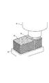
- Explanatory drawing explaining the laminated body of the tempered glass which is a process target.
- FIG. 13 is an enlarged photograph showing a portion A (magnification: 270 times).
- Fig. 13 is an enlarged photograph showing part B (magnification: 270x).
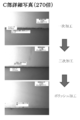
- Fig. 13 is an enlarged photograph showing part C (magnification: 270x).
- FIG. 13 is an enlarged photograph showing a portion D (magnification: 270 times).
- FIG. 13 is an enlarged photograph showing the E portion (magnification: 270 times).
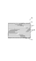
- the ultrasonic vibration processing device 4 includes a processing device main body 5 as shown in FIG.
- the processing apparatus main body 5 includes a relatively long bottomed cylindrical housing 6, a vibration device (vibration mechanism) 7 held in the housing 6, and the vibration device. 7 and a motor 9 as a rotational drive source for rotationally driving the excitation device 7.
- the housing 6 has an elevating device (only a part (attachment portion to the housing 6 is shown in FIG. 2)) 10 with its axis extending in the vertical direction and its opening facing downward. Installed on.
- the elevating device 10 has a function of moving the housing 6 up and down in the vertical direction and adjusting the elevating speed at that time (see arrows). With the function of the elevating device 10, the housing 6 is predetermined during processing. It is lowered at the set speed (feed speed).
- the ultrasonic vibration generating unit 12 is held in the holding hole in the lower end surface of the body part 11.
- the ultrasonic vibration generating unit 12 is configured in a state where an ultrasonic vibrator, a vibration transmitting unit, and an amplifying unit are connected in series, and these are formed from the inside of the holding hole of the body unit 11.
- the ultrasonic transducer, the vibration transmission unit, and the amplification unit are arranged in this order toward the opening side.
- the ultrasonic vibrator has a piezoelectric body and a metal block for bolting the piezoelectric body, and electrodes (not shown) are arranged between the piezoelectric bodies and between the piezoelectric body and the metal blocks.
- the vibration transmission unit has a function of transmitting the vibration of the ultrasonic transducer to the amplification unit, and the amplification unit has a function of amplifying the vibration transmitted from the vibration transmission unit.
- the motor 9 is attached to the outer surface (upper surface) of the bottom 6a of the housing 6.
- a through hole 15 is formed in the bottom portion 6a of the housing 6 so as to penetrate the inside and outside of the housing 6.
- the drive shaft 9a of the motor 9 passes through the through hole 15 and is fitted into the mounting cylinder portion 14 in the body portion 11. It is held together (fixed). Thereby, the driving force of the motor 9 is transmitted to the processing tool 8 via the body part 11 and the ultrasonic vibration generating unit 12, and the processing tool 8 can rotate about its axis.
- the ultrasonic oscillator 16 is to adjust an input electric signal (specifically, voltage or current) and apply the adjusted electric signal to the ultrasonic vibration generating unit 12 (ultrasonic vibrator).
- the amplitude and frequency (frequency) of the input voltage from the power source are adjusted under a constant current (for example, a predetermined value of 1 to 2 A), and the adjusted voltage signal (for example, 300 to 400 V) is obtained.
- a constant current for example, a predetermined value of 1 to 2 A
- the adjusted voltage signal for example, 300 to 400 V
- a current signal may be applied to the ultrasonic transducer under a constant voltage.
- the ultrasonic vibration processing apparatus 4 includes a control unit U as a control unit that feedback-controls the ultrasonic oscillator 16 (ultrasonic vibration generating unit 12) and the motor 9. I have.
- a voltage signal (voltage amplitude, frequency signal) from the ultrasonic oscillator 16 and a rotation speed signal (voltage signal) of the motor 9 are input to the control unit U, while an ultrasonic wave is input from the control unit U. Control signals are output to the oscillator 16 and the motor 9, respectively.
- the control unit U includes a setting unit (setting unit) for setting a target value for feedback control, and a determination unit that determines an operation variable based on a deviation between the target value of the setting unit and the control variable. (Determination unit) and an execution control unit (execution control unit) that outputs a control signal to execute an operation variable from the determination unit.
- the setting unit sets a target amplitude and a target frequency with respect to an input voltage to the ultrasonic vibration generation unit 12 (ultrasonic transducer) as target values for feedback control.
- quality deterioration occurrence values values that generate cracks, chipping exceeding a predetermined value, etc.
- the target amplitude of the input voltage to the ultrasonic vibration generating unit 12 is finally a predetermined amplitude (preferably 8 ⁇ m) in the range where the amplitude of the processing tool 8 is in the range of 3 ⁇ m to 9 ⁇ m (not belonging to the range of the quality deterioration occurrence value).
- the amplitude of the processing tool 8 is less than 3 ⁇ m or more than 9 ⁇ m, the quality deterioration occurrence value range is set.
- the target amplitude is set in the range of 3 ⁇ m to 9 ⁇ m in the final amplitude of the processing tool 8 because, based on the knowledge obtained by the present inventor, the processing capability is not sufficient below 3 ⁇ m (cutting chips). Etc., and the cutting resistance etc.
- the frequency of the processing tool 8 is finally in the range of 60 kHz to 64 kHz (not belonging to the range of the quality deterioration occurrence value).
- the frequency of the processing tool 8 is set to be a predetermined frequency (preferably 63 kHz) and the frequency of the processing tool 8 is less than 60 kHz and more than 64 kHz, the quality deterioration occurrence value range is set.
- the target frequency is set to 60 kHz to 64 kHz in the final frequency of the processing tool 8 based on the knowledge of the inventors of the present invention.
- the target current for the motor 9 is set so that the rotational speed of the processing tool 8 finally becomes a predetermined rotational speed (preferably 5000 rpm) in the range of 2000 rpm to 30000 rpm.
- the rotational speed of the processing tool 8 is in the range of 2000 rpm to 30000 rpm. If the rotational speed is less than 2000 rpm, the effect of processing on the tempered glass is not sufficient. This is because the effect of processing is reduced to cause a problem from the viewpoint of durability.
- the execution control unit is to output each operation variable from the determination unit to the ultrasonic oscillator 16 and the motor 9 as a control signal.
- the output voltage (amplitude, frequency) from the ultrasonic oscillator 16 is adjusted, and the processing tool 8 is feedback controlled so as to have a predetermined vertical amplitude and a predetermined frequency.
- the rotational speed is feedback controlled, and the processing tool 8 is maintained at a predetermined rotational speed.
- 0.2 msec is set as the lower limit because it is the lowest limit that can be obtained at the present time, and feedback control cannot be actually performed with a sample period less than that value. . It will be more preferable if a value of less than 0.2 msec is developed in the future.
- the analog / digital conversion function and the arithmetic processing capability of the CPU are speeded up as compared with the conventional one in order to speed up the sampling period of the feedback control.
- the frequency (frequency) of the processing tool 8 is set to 80 kHz and the sample period is set to 0.2 msec, before the oscillation occurs in the optimum environment corresponding to the load variation.
- the vibration impact applied to the tempered glass can be suppressed to 16 times.
- the oscillation environment is optimized with a sample period of 0.2 msec under the feed rate of the processing tool 8 of 30 mm / min, the progress of the processing is feedback-controlled every 0.1 ⁇ m. It is possible to cope with (follow up) a minute state change (stress change).
- Such 5 ⁇ m is a value that is relatively large with respect to the surface reinforced layer of several tens of ⁇ m, and the response for each 5 ⁇ m cannot follow the state change of the tempered glass. As a result, processing must be performed while applying stress to the tempered glass, and cracks and the like are generated in the tempered glass.
- Target value of control, etc. is supported by the following processing experiments 1 to 3 conducted by the present inventors.
- the processing experiments 1 to 3 were performed on the tempered glass under the following common experimental conditions, and the evaluation was performed based on the following common evaluation criteria.
- Tempered glass base material as processing object for common experimental conditions Aluminosilicate glass Base material thickness ⁇ 1: 0.70 mm
- Compressive residual stress of the surface reinforcing layer 600 MPa to 700 MPa
- Processing tool 8 Processing feed rate: 60mm / min
- Particle size of processing tool 8 # 600
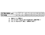
- the target frequency of the processing tool 8 is preferably 60 kHz to 64 kHz (particularly 63 kHz) (less than 60 kHz and those exceeding 64 kHz are within the range of quality deterioration occurrence values). did.
- the contents shown in FIG. 5 were obtained. According to the contents shown in FIG. 5, it was found that the amplitude of the processing tool 8 is preferably 3 ⁇ m to 9 ⁇ m (particularly 8 ⁇ m) (less than 3 ⁇ m and those exceeding 9 ⁇ m are within the range of quality deterioration occurrence values).
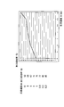
- Processing experiment 3 (e-1) Focusing on the importance of the sample period for feedback control of processing for tempered glass that undergoes a minute state change during processing, target amplitude of processing tool 8: 8 ⁇ m, target frequency of processing tool 8 : An experiment was conducted in which the sampling period (response speed) of feedback control was changed under the condition of fixing at 63 kHz.
- FIG. 7 shows the relationship between the feedback control sample period (response speed) and the machining success rate. According to FIG. 7, the smaller the response speed, the higher the machining success rate. In particular, at 0.5 ms or less, the machining success rate increased with a sudden rise.
- the evaluation of the processing success is the same as the above-described evaluation ( ⁇ ). In FIG. 6, the processing success rate of 87% or more was evaluated as “ ⁇ ”.
- a tempered glass having a surface reinforcing layer 3 (specifically, a base material having a thickness of 0.7 mm, a surface reinforcing layer having a thickness of 40 ⁇ m or more, and a surface compressive stress of 600 MPa or more) 1
- a large board This is for cutting out a predetermined shape from a large substrate in order to produce protective glasses for portable terminals, tablets, and the like.
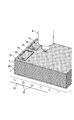
- a laminated body in which a plurality of (for example, 12) large substrates (tempered glass 1) are bonded in a laminated state with an adhesive 20 (adhesive layer 80 ⁇ m to 100 ⁇ m).
- Glass group 1A is prepared.
- the adhesive 20 is preferably a UV curable adhesive or the like that is cured by ultraviolet rays and is melted by warm water. This is because it is necessary to quickly cure the adhesive, and finally to peel off each tempered glass cut out.
- the glass 1n which comprises the outermost surface (front surface, back surface) of 1 A of laminated bodies, you may use normal glass with low cost instead of tempered glass. This is because the outermost surface of the laminate 1A tends to be particularly susceptible to chipping.
- substrate (tempered glass 1) with a base material thickness of 0.5 mm you may prepare the laminated body 1A which adhered 16 sheets.
- a plurality of portable terminal protective glass sizes are cut out from the laminate 1A.
- grinding is performed so as to form the long holes 23 and the square holes 24 in the respective laminated blocks 1a.
- the laminated body 1A other than the laminated block 1a is removed, and as shown in FIG. 12, the outer periphery of each laminated block 1a, the long hole 23
- finish grinding is performed on the square hole 24.
- each laminated block 1a is maintained in a state of being fixed to the fixed base 21 based on the suction action.
- the fixed base 21 is shown in a contracted state, and the long holes 23 and the square holes 24 formed in the laminated block 1a are omitted.
- the processing tool 8 is rotated at a predetermined rotational speed of 5000 rpm within a range of 2000 rpm to 30000 rpm. This is to obtain a preferable effect by the rotation of the processing tool 8 while sufficiently exerting the effect of the ultrasonic vibration processing.
- general conditions are used for other processing conditions.
- the above-described ultrasonic vibration processing device 4 is used in the primary processing and the secondary processing, and the processing conditions in the primary processing and the secondary processing are as follows.
- Primary processing condition processing tool 8 Type Axial diamond wheel (grain size: # 320) Diameter: 1.5mm Feeding speed: 60mm / min Amplitude: 8 ⁇ m Frequency: 63kHz Sample period (response speed) of feedback control: 0.2 msec Rotation speed: 5000rpm
- Secondary processing condition processing tool 8 Type Axial diamond wheel (grain size: # 600) Diameter: 1.5mm Feeding speed: 60mm / min Amplitude: 5 ⁇ m Frequency: 63kHz Sample period (response speed) of feedback control: 0.2 msec Rotation speed: 5000rpm
- each part A to E of the test glass is in any processing stage (after primary processing, secondary processing, polishing Even in the state of (after processing), a good processing state was shown.
- Primary processing condition processing tool 8 Type Axial diamond wheel (grain size: # 320) Diameter: 1.5mm Feeding speed: 60mm / min Amplitude: 8 ⁇ m Frequency: 50kHz Sample period (response speed) of feedback control: 10 msec Rotation speed: 5000rpm
Landscapes
- Engineering & Computer Science (AREA)
- Mechanical Engineering (AREA)
- Chemical & Material Sciences (AREA)
- Materials Engineering (AREA)
- Organic Chemistry (AREA)
- Inorganic Chemistry (AREA)
- Ceramic Engineering (AREA)
- Mining & Mineral Resources (AREA)
- Physics & Mathematics (AREA)
- General Physics & Mathematics (AREA)
- Automation & Control Theory (AREA)
- Life Sciences & Earth Sciences (AREA)
- Geochemistry & Mineralogy (AREA)
- General Chemical & Material Sciences (AREA)
- Chemical Kinetics & Catalysis (AREA)
- Quality & Reliability (AREA)
- Manufacturing & Machinery (AREA)
- General Engineering & Computer Science (AREA)
- Computer Vision & Pattern Recognition (AREA)
- Artificial Intelligence (AREA)
- Health & Medical Sciences (AREA)
- Evolutionary Computation (AREA)
- Medical Informatics (AREA)
- Software Systems (AREA)
- Grinding And Polishing Of Tertiary Curved Surfaces And Surfaces With Complex Shapes (AREA)
- Re-Forming, After-Treatment, Cutting And Transporting Of Glass Products (AREA)
- Surface Treatment Of Glass (AREA)
- Apparatuses For Generation Of Mechanical Vibrations (AREA)
Abstract
Description
Assistant)等の表示装置には、一般に化学強化された強化ガラスが用いられている。この強化ガラスは、ガラス母材の表面側に表面強化層(化学強化層)が設けられた構成とされており、これに基づき、強化ガラスは、薄板化を図りつつ、曲げ応力、衝撃に対して高強度を示している。
加工具を加振させつつ回転させた状態の下で、該加工具をもって、表面強化層を有する強化ガラスに対して加工を行う強化ガラスの加工方法において、
前記強化ガラスに対する前記加工具による加振を、該加工具の振幅及び振動数が目標振幅及び目標振動数にそれぞれ近づくようにフィードバック制御すると共に、該目標振幅及び目標振動数を、該強化ガラスの加工に伴う該強化ガラスの厚み方向各部において変化する値であって該強化ガラスの品質を悪化させる品質悪化発生値の範囲に属さないものにそれぞれ設定し、
しかも、前記フィードバック制御におけるサンプル周期として、0.3msec以下の所定サンプル周期を用いる構成とされている。この請求項1の好ましい態様としては、請求項2~4の記載の通りとなる。
加工具を加振させつつ回転させた状態の下で、該加工具をもって、表面強化層を有する強化ガラスに対して加工を行う強化ガラス用加工装置において、
前記加工具を前記強化ガラスに向けて加振させる加振機構と、
前記加振機構を調整する加振調整手段と、
前記加振調整手段を制御して、前記強化ガラスに対する前記加工具による加振を、該加工具の振幅及び振動数が目標振幅及び目標振動数にそれぞれ近づくようにフィードバック制御すると共に、該目標振幅及び目標振動数を、前記強化ガラスの加工に伴う該強化ガラスの厚み方向各部において変化する値であって該強化ガラスの品質を悪化させる品質悪化発生値の範囲に属さないものに設定し、さらには、前記フィードバック制御を、0.3msec以下の所定サンプル周期毎に実行させる制御手段と、
を備えている構成とされている。この請求項5の好ましい態様としては、請求項6以下の記載の通りとなる。
1.先ず、強化ガラスの加工方法を説明する前に先立ち、その加工方法の加工対象となる強化ガラス、その加工方法を使用する強化ガラス用加工装置としての超音波振動加工装置について説明する。
(1)強化ガラス
強化ガラス1は、図1に示すように、ガラス母材(例えばアルミノシリケートガラス)2の表面側(裏面側)に表面強化層(化学強化層)3が設けられた構成とされている。この表面強化層3により、強化ガラス1は、薄板化を図りつつ、曲げ応力、衝撃に対して高強度が確保されることになっている。具体的には、強化ガラス1としては、母材2の厚みδ1が0.7mm前後、表面強化層3の厚みδ2が40μm以上(現在の時点で70μmのものが開発されているが、勿論、加工の対象)、表面圧縮応力が600MPa~700MPaとされたものが対象とされている。勿論、強化ガラス1だけでなく通常のガラスも、超音波振動加工装置の加工対象となる。
(2)超音波振動加工装置
(i)超音波振動加工装置4は、図2に示すように、加工装置本体5を備えている。
上記制御の目標値等は、本件発明者が行った下記加工実験1~3に裏付けられている。この場合、加工実験1~3は、下記共通実験条件の下で強化ガラスに対して行い、その評価は下記共通の評価基準に基づいて行った。
加工対象としての強化ガラス
母材材質:アルミノシリケートガラス
母材厚みδ1:0.70mm
表面強化層の厚みδ2:40μm(0.04mm)
表面強化層の圧縮残留応力:600MPa~700MPa
加工具8
加工送り速度:60mm/分
回転数:5000rpm
軸状の加工具径:1.5mm
加工具8の粒度:♯600番
(b)共通の評価基準
×:強化ガラスが割れた
△:チッピング100~150μm(加工ができるが、品質が悪い状態)
○:チッピング30μm以下(加工、品質共に良い状態)
(c-1)1枚の強化ガラスに対する加工具8の良好な振動数を得るために電圧を調整することにより、加工具8の目標振幅:8μm、フィードバックのサンプル周期(応答速度):0.2msecに固定した条件の下で、加工具8の目標振動数(目標周波数)を変化させる実験を行った。
(d-1)1枚の強化ガラスに対する加工具8の良好な目標振幅を得るために電圧を調整することにより、加工具8の目標周波数:63kHz、フィードバックのサンプル周期(応答速度):0.2msecに固定した条件の下で、加工具8の目標振幅を変化させる実験を行った。
(e-1)加工中に微細な状態変化を起こす強化ガラスにとって、その加工のフィードバック制御のサンプル周期が重要であることに着目し、加工具8の目標振幅:8μm、加工具8の目標周波数:63kHzに固定した条件の下で、フィードバック制御のサンプル周期(応答速度)を変化させる実験を行った。
(1)本件方法を用いて作成した試験用ガラスの場合
試験用ガラスとして、図13に示す携帯端末用保護ガラス1Pを作成することを試みた。
試験用ガラスの作成方法は、前述の強化ガラスの加工方法と同様である。すなわち、表面強化層を有する強化ガラス(具体的には、母材材質:アルミノシリケートガラス、母材厚み0.7mm、表面強化層40μm、表面圧縮応力600MPaのもの)が大板基板とされたもの12枚を、UV硬化接着剤等を用いることにより積層固定状態としたものを用意し、それから携帯端末用保護ガラスの大きさのもの(積層ブロック1a)を切り出し、その切り出したものに対して、長孔23、角孔24の研削加工を行って(一次加工)、一次加工品(積層体)を作成する。次に、一次加工品における外周、長孔23、角孔24の面取り仕上げ加工(二次加工)を行い、二次加工品(積層体)を作成する。次に、二次加工品に対してポリッシュ加工を行い、その後、加工を終えた積層ブロック1aの各ガラス板を温水に漬けて剥がし、試験用(評価用)ガラスを得る。
一次加工条件
加工具8
種類:軸状のダイヤモンド砥石(粒度:♯320番)
直径:1.5mm
送り速度:60mm/min
振幅:8μm
振動数:63kHz
フィードバッグ制御のサンプル周期(応答速度):0.2msec
回転数:5000rpm
二次加工条件
加工具8
種類:軸状のダイヤモンド砥石(粒度:♯600番)
直径:1.5mm
送り速度:60mm/min
振幅:5μm
振動数:63kHz
フィードバッグ制御のサンプル周期(応答速度):0.2msec
回転数:5000rpm
図13に示す試験用ガラスの各部A~Eにおける一次加工後、二次加工後、ポリッシュ加工後の加工状態を確認した。
(2)従前の方法を用いて作成した試験用ガラスの場合
本件方法による試験用ガラスの場合同様、試験用ガラスとして、図13に示す携帯端末用保護ガラスを作成することを試みた。
前述の本件方法同様、12枚の大板基板(表面強化層を有する強化ガラス)を積層状態をもって接着したものを用意し、それに対して、下記一次加工条件の下で、一次加工(積層ブロック1aの切り出し、長孔23、角孔24の加工)を行おうとした。しかし、積層ブロック1aの切り出し後、一次加工における長孔23の加工初期に、早々と複数のクラックが生じた。このため、比較例に係る試験用ガラスの孔加工に関する部分(D部,E部(図13参照))に関しては、一次加工における角孔24の加工を含め、以後の加工を行うことを断念した。また、比較例に係る試験用ガラスの外周面に関する部分(A部~C部(図13参照))のうち、B部、C部に関しては、二次加工、ポリッシュ加工を行ったが、A部に関しては、クラックが入ったため、以後の加工を断念した。
一次加工条件
加工具8
種類:軸状のダイヤモンド砥石(粒度:♯320番)
直径:1.5mm
送り速度:60mm/min
振幅:8μm
振動数:50kHz
フィードバッグ制御のサンプル周期(応答速度):10msec
回転数:5000rpm
比較例に係る試験用ガラスの各部A~D(図13参照)において、一次加工後の加工状態を確認したところ、図19~図21(270倍)、図22に示す拡大写真図(90倍)に示す結果となった。すなわち、比較例に係る試験用ガラスの各部A~Cでは、クラック又は所定以上のチッピングが生じ、D部では、複数の大きなクラックが発生し、製品として成立し得ない品質のものとなった。図22中、中央の大きな穴は、長孔23に至る前の加工初期の穴である。
1A 積層体(積層ガラス群)
1a 積層ブロック(積層ガラス群)
3 表面強化層
4 超音波振動加工装置
7 加振装置(加振機構)
8 加工具
9 モータ(回転駆動源)
16 超音波発振器(加振調整手段)
U 制御ユニット(制御手段)
Claims (7)
- 加工具を加振させつつ回転させた状態の下で、該加工具をもって、表面強化層を有する強化ガラスに対して加工を行う強化ガラスの加工方法において、
前記強化ガラスに対する前記加工具による加振を、該加工具の振幅及び振動数が目標振幅及び目標振動数にそれぞれ近づくようにフィードバック制御すると共に、該目標振幅及び目標振動数を、該強化ガラスの加工に伴う該強化ガラスの厚み方向各部において変化する値であって該強化ガラスの品質を悪化させる品質悪化発生値の範囲に属さないものにそれぞれ設定し、
しかも、前記フィードバック制御におけるサンプル周期として、0.3msec以下の所定サンプル周期を用いる、
ことを特徴とする強化ガラスの加工方法 - 請求項1において、
前記目標振幅を3μm~9μmの範囲の所定振幅とすると共に、前記目標振動数を60kHz~64kHzの範囲の所定振動数にする、
ことを特徴とする強化ガラスの加工方法。 - 請求項1又は2において、
前記加工具の回転数を、2000rpm~30000rpmの範囲内の所定回転数とする、
ことを特徴とする強化ガラスの加工方法。 - 請求項1~3のいずれか1項において、
前記表面強化層を有する強化ガラスが、該強化ガラスを複数枚積層して構成される積層ガラス群を含んでいる、
ことを特徴とする強化ガラスの加工方法。 - 加工具を加振させつつ回転させた状態の下で、該加工具をもって、表面強化層を有する強化ガラスに対して加工を行う強化ガラス用加工装置において、
前記加工具を前記強化ガラスに向けて加振させる加振機構と、
前記加振機構を調整する加振調整手段と、
前記加振調整手段を制御して、前記強化ガラスに対する前記加工具による加振を、該加工具の振幅及び振動数が目標振幅及び目標振動数にそれぞれ近づくようにフィードバック制御すると共に、該目標振幅及び目標振動数を、前記強化ガラスの加工に伴う該強化ガラスの厚み方向各部において変化する値であって該強化ガラスの品質を悪化させる品質悪化発生値の範囲に属さないものに設定し、さらには、前記フィードバック制御を、0.3msec以下の所定サンプル周期毎に実行させる制御手段と、
を備えている、
ことを特徴とする強化ガラス用加工装置。 - 請求項5において、
前記制御手段は、前記目標振幅を3μm~9μmの範囲の所定振幅に設定していると共に、前記目標振動数を60kHz~64kHzの範囲の所定振動数に設定している、
ことを特徴とする強化ガラス用加工装置。 - 請求項5又は6において、
前記制御手段は、前記加工具の回転数を、2000rpm~30000rpmの範囲内の所定回転数となるように設定されている、
ことを特徴とする強化ガラス用加工装置。
Priority Applications (20)
| Application Number | Priority Date | Filing Date | Title |
|---|---|---|---|
| EP12883471.0A EP2891635B1 (en) | 2012-08-31 | 2012-08-31 | Method for processing toughened glass and processing device for toughened glass |
| US14/414,757 US9290412B2 (en) | 2012-08-31 | 2012-08-31 | Method of processing tempered glass and device of processing tempered glass |
| KR1020147001952A KR101442460B1 (ko) | 2012-08-31 | 2012-08-31 | 강화유리의 가공방법 및 강화유리용 가공장치 |
| CN201280033936.3A CN103958425B (zh) | 2012-08-31 | 2012-08-31 | 强化玻璃的加工方法及强化玻璃用加工装置 |
| PCT/JP2012/072137 WO2014033905A1 (ja) | 2012-08-31 | 2012-08-31 | 強化ガラスの加工方法及び強化ガラス用加工装置 |
| JP2012556314A JP5422756B1 (ja) | 2012-08-31 | 2012-08-31 | 強化ガラスの加工方法及び強化ガラス用加工装置 |
| TW102102607A TWI455901B (zh) | 2012-08-31 | 2013-01-24 | 強化玻璃之加工方法及強化玻璃用加工裝置 |
| KR1020157004674A KR101562769B1 (ko) | 2012-08-31 | 2013-07-31 | 강화 유리용 가공구, 강화 유리용 가공 장치 및 강화 유리용 가공구의 사용 방법 |
| EP13833432.1A EP2891636B1 (en) | 2012-08-31 | 2013-07-31 | Method and apparatus for processing tempered glass |
| JP2014532894A JP5715737B2 (ja) | 2012-08-31 | 2013-07-31 | 強化ガラスの加工方法、強化ガラス用加工装置及び強化ガラス用加工具の使用方法 |
| PCT/JP2013/070758 WO2014034366A1 (ja) | 2012-08-31 | 2013-07-31 | 強化ガラス用加工具、強化ガラス用加工装置及び強化ガラス用加工具の使用方法 |
| US14/421,596 US9393661B2 (en) | 2012-08-31 | 2013-07-31 | Method of using device of processing tempered glass |
| CN201380045625.3A CN104603074B (zh) | 2012-08-31 | 2013-07-31 | 强化玻璃用加工工具、强化玻璃用加工装置及强化玻璃用加工工具的使用方法 |
| PCT/JP2013/073447 WO2014034907A1 (ja) | 2012-08-31 | 2013-08-30 | 強化ガラスの加工方法 |
| CN201380045587.1A CN104603073B (zh) | 2012-08-31 | 2013-08-30 | 强化玻璃的加工方法 |
| KR1020157004890A KR101562770B1 (ko) | 2012-08-31 | 2013-08-30 | 강화유리의 가공 방법 |
| US14/424,388 US9700983B2 (en) | 2012-08-31 | 2013-08-30 | Method of processing tempered glass |
| EP13832513.9A EP2891634B1 (en) | 2012-08-31 | 2013-08-30 | Method of processing tempered glass |
| JP2014533138A JP5695279B2 (ja) | 2012-08-31 | 2013-08-30 | 強化ガラスの加工方法 |
| US14/829,089 US20150353412A1 (en) | 2012-08-31 | 2015-08-18 | Method of processing tempered glass and apparatus of processing tempered glass |
Applications Claiming Priority (1)
| Application Number | Priority Date | Filing Date | Title |
|---|---|---|---|
| PCT/JP2012/072137 WO2014033905A1 (ja) | 2012-08-31 | 2012-08-31 | 強化ガラスの加工方法及び強化ガラス用加工装置 |
Related Child Applications (2)
| Application Number | Title | Priority Date | Filing Date |
|---|---|---|---|
| US14/414,757 A-371-Of-International US9290412B2 (en) | 2012-08-31 | 2012-08-31 | Method of processing tempered glass and device of processing tempered glass |
| US14/829,089 Division US20150353412A1 (en) | 2012-08-31 | 2015-08-18 | Method of processing tempered glass and apparatus of processing tempered glass |
Publications (1)
| Publication Number | Publication Date |
|---|---|
| WO2014033905A1 true WO2014033905A1 (ja) | 2014-03-06 |
Family
ID=50182753
Family Applications (3)
| Application Number | Title | Priority Date | Filing Date |
|---|---|---|---|
| PCT/JP2012/072137 WO2014033905A1 (ja) | 2012-08-31 | 2012-08-31 | 強化ガラスの加工方法及び強化ガラス用加工装置 |
| PCT/JP2013/070758 WO2014034366A1 (ja) | 2012-08-31 | 2013-07-31 | 強化ガラス用加工具、強化ガラス用加工装置及び強化ガラス用加工具の使用方法 |
| PCT/JP2013/073447 WO2014034907A1 (ja) | 2012-08-31 | 2013-08-30 | 強化ガラスの加工方法 |
Family Applications After (2)
| Application Number | Title | Priority Date | Filing Date |
|---|---|---|---|
| PCT/JP2013/070758 WO2014034366A1 (ja) | 2012-08-31 | 2013-07-31 | 強化ガラス用加工具、強化ガラス用加工装置及び強化ガラス用加工具の使用方法 |
| PCT/JP2013/073447 WO2014034907A1 (ja) | 2012-08-31 | 2013-08-30 | 強化ガラスの加工方法 |
Country Status (7)
| Country | Link |
|---|---|
| US (4) | US9290412B2 (ja) |
| EP (3) | EP2891635B1 (ja) |
| JP (1) | JP5422756B1 (ja) |
| KR (3) | KR101442460B1 (ja) |
| CN (3) | CN103958425B (ja) |
| TW (1) | TWI455901B (ja) |
| WO (3) | WO2014033905A1 (ja) |
Families Citing this family (14)
| Publication number | Priority date | Publication date | Assignee | Title |
|---|---|---|---|---|
| EP2891635B1 (en) * | 2012-08-31 | 2017-05-03 | Ceron Technologies Inc. | Method for processing toughened glass and processing device for toughened glass |
| CN104973763B (zh) * | 2014-04-11 | 2018-02-27 | 深圳市远东皓星科技有限公司 | 玻璃叠合机及玻璃叠合方法 |
| KR101703029B1 (ko) | 2014-08-29 | 2017-02-07 | 주식회사 태성기연 | 샌드 브라스트방식의 강화유리 절단장치 |
| US10384324B2 (en) | 2015-02-02 | 2019-08-20 | Corning Incorporated | Methods for strengthening edges of laminated glass articles and laminated glass articles formed therefrom |
| TW201632272A (zh) * | 2015-03-04 | 2016-09-16 | 中原大學 | 超音波輔助加工感測及傳動系統 |
| RU2671239C1 (ru) * | 2015-06-10 | 2018-10-30 | Бандо Кико Ко., Лтд. | Способ вырезания листового стекла и позиционирования вырезанного листового стекла и устройство для его осуществления |
| KR101819608B1 (ko) | 2015-07-31 | 2018-01-17 | 코닝정밀소재 주식회사 | 유리 접합체 커팅 방법 및 커팅 장치 |
| EP3433065A1 (en) | 2016-03-24 | 2019-01-30 | Corning Incorporated | Laminated glass article with aperture formed therein and methods for forming the same |
| JP6939581B2 (ja) * | 2018-01-10 | 2021-09-22 | Agc株式会社 | 曲面ガラス基板の加工方法及び製造方法 |
| CN108640494B (zh) * | 2018-04-24 | 2020-02-14 | 昆山国显光电有限公司 | 显示屏开槽方法及显示屏 |
| CN109485246A (zh) * | 2018-10-23 | 2019-03-19 | 意力(广州)电子科技有限公司 | 一种小型玻璃的数控加工工艺 |
| DE102018132320A1 (de) * | 2018-12-14 | 2020-06-18 | Bohle Ag | Schneidewerkzeugeinheit für eine Glasschneide-Werkzeugmaschine und entsprechende Glasschneide-Werkzeugmaschine |
| DE202018006838U1 (de) | 2018-12-14 | 2023-07-18 | Bohle Ag | Schneidewerkzeugeinheit für eine Glasschneide-Werkzeugmaschine und entsprechende Glasschneide-Werkzeugmaschine |
| KR102505511B1 (ko) * | 2020-08-13 | 2023-03-03 | (주)피엔피 | 초박형 유리 박리 전처리장치 |
Citations (4)
| Publication number | Priority date | Publication date | Assignee | Title |
|---|---|---|---|---|
| JP2002346817A (ja) * | 2001-05-21 | 2002-12-04 | Masao Murakawa | 超音波ミリング装置 |
| JP2004083378A (ja) | 2002-08-29 | 2004-03-18 | Central Glass Co Ltd | 化学強化ガラス |
| JP2008007384A (ja) * | 2006-06-30 | 2008-01-17 | Optrex Corp | ガラス基板の製造方法 |
| JP2012031018A (ja) | 2010-07-30 | 2012-02-16 | Asahi Glass Co Ltd | 強化ガラス基板及び強化ガラス基板の溝加工方法と強化ガラス基板の切断方法 |
Family Cites Families (31)
| Publication number | Priority date | Publication date | Assignee | Title |
|---|---|---|---|---|
| JPH02109667A (ja) * | 1988-10-13 | 1990-04-23 | Office Natl Etud Rech Aerospat <Onera> | 超音波研削機械 |
| JPH0463668A (ja) * | 1990-07-03 | 1992-02-28 | Brother Ind Ltd | 超音波加工機の振幅制御装置 |
| SE514525E (sv) * | 1998-10-22 | 2010-02-16 | Staffansboda Cie Ab | Anordning och metod för styrning av vibrationer samt verktygshållare |
| DE19851353C1 (de) * | 1998-11-06 | 1999-10-07 | Schott Glas | Verfahren und Vorrichtung zum Schneiden eines Laminats aus einem sprödbrüchigen Werkstoff und einem Kunststoff |
| JP2002160932A (ja) * | 2000-11-17 | 2002-06-04 | Sony Corp | ガラス基板の製造方法、ガラス基板、およびガラス基板を有する電子機器 |
| JP3806603B2 (ja) * | 2001-02-23 | 2006-08-09 | Towa株式会社 | 楕円振動装置及び楕円振動装置の制御方法 |
| US7259496B2 (en) * | 2002-04-08 | 2007-08-21 | University Of North Carolina At Charlotte | Tunable vibratory actuator |
| JP2003305716A (ja) | 2002-04-16 | 2003-10-28 | Asahi Techno Glass Corp | 脆性材料用孔明け装置 |
| JP2006018922A (ja) | 2004-07-01 | 2006-01-19 | Hoya Corp | 磁気ディスク用ガラス基板の製造方法及び磁気ディスクの製造方法 |
| CN100479957C (zh) * | 2004-07-02 | 2009-04-22 | 索尔有限公司 | 振动头-刀具 |
| KR100637803B1 (ko) * | 2004-12-02 | 2006-10-23 | 씨티에스(주) | 초음파진동을 이용한 유리절단장치 |
| EP1669148B1 (de) * | 2004-12-13 | 2018-01-17 | Fritz Studer AG | Werkzeugeinheit zur ultraschallunterstützten rotativen Bearbeitung |
| KR100712544B1 (ko) * | 2006-01-10 | 2007-05-02 | 삼성전자주식회사 | 직류 모터의 반복적 허위 속도 오차 보상 장치 및 방법과이를 이용한 디스크 드라이브 |
| JP5115198B2 (ja) * | 2006-02-08 | 2013-01-09 | コニカミノルタアドバンストレイヤー株式会社 | 切削用振動体及び加工装置 |
| US7819009B2 (en) * | 2006-02-28 | 2010-10-26 | Frederic Borah | Vibration Monitoring System |
| JP2010001160A (ja) * | 2006-10-16 | 2010-01-07 | Panasonic Corp | ガラス切断方法およびその装置 |
| JP4625963B2 (ja) * | 2007-03-02 | 2011-02-02 | 独立行政法人国立高等専門学校機構 | 振動加工装置とホルダー |
| TWI337559B (en) * | 2007-12-20 | 2011-02-21 | Ind Tech Res Inst | Spindle and flexure hinge used in ultrasonic machine |
| TW200932468A (en) * | 2008-01-21 | 2009-08-01 | Grain Electronics Inc | Glass processing apparatus and method |
| JP2009184878A (ja) * | 2008-02-06 | 2009-08-20 | Shuko Denshi Kogyo Yugenkoshi | ガラス加工装置及びガラス加工方法 |
| JP5197102B2 (ja) * | 2008-03-31 | 2013-05-15 | 雅彦 神 | 超音波スピンドル装置、超音波スピンドル装置の工具連結方法、工具連結装置、工具連結方法及び工具交換システム |
| JP2009256125A (ja) | 2008-04-15 | 2009-11-05 | Shoda Techtron Corp | 板ガラスの加工方法 |
| TW201036735A (en) * | 2009-04-14 | 2010-10-16 | lu-jia Liao | Glass processing equipment and processing method |
| KR101048069B1 (ko) * | 2009-06-30 | 2011-07-11 | 세메스 주식회사 | 초음파를 이용한 스크라이빙 유닛 |
| TW201202155A (en) * | 2010-07-09 | 2012-01-16 | Easy Field Corp | Method of using ultrasonic pulse to process glass substrate |
| WO2012096053A1 (ja) * | 2011-01-11 | 2012-07-19 | 旭硝子株式会社 | 強化ガラス板の切断方法 |
| JP4891445B1 (ja) * | 2011-03-17 | 2012-03-07 | パナソニック電工株式会社 | 超精密複合加工装置および超精密複合加工方法 |
| DE102011016210B3 (de) * | 2011-04-06 | 2012-03-08 | Grenzebach Maschinenbau Gmbh | Vorrichtung und Verfahren zum Ablängen eines Float-Glas-Bandes mit normaler oder strukturierter Oberfläche, Computerprogramm und maschinenlesbarer Träger |
| AT511551B1 (de) * | 2011-05-18 | 2013-10-15 | Univ Wien Tech | Vorrichtung und verfahren zur mechanischen bearbeitung eines werkstücks |
| JP5908342B2 (ja) * | 2012-05-17 | 2016-04-26 | オークマ株式会社 | 工作機械の加工振動抑制方法及び加工振動抑制装置 |
| EP2891635B1 (en) * | 2012-08-31 | 2017-05-03 | Ceron Technologies Inc. | Method for processing toughened glass and processing device for toughened glass |
-
2012
- 2012-08-31 EP EP12883471.0A patent/EP2891635B1/en not_active Not-in-force
- 2012-08-31 CN CN201280033936.3A patent/CN103958425B/zh not_active Expired - Fee Related
- 2012-08-31 US US14/414,757 patent/US9290412B2/en not_active Expired - Fee Related
- 2012-08-31 KR KR1020147001952A patent/KR101442460B1/ko active IP Right Grant
- 2012-08-31 JP JP2012556314A patent/JP5422756B1/ja not_active Expired - Fee Related
- 2012-08-31 WO PCT/JP2012/072137 patent/WO2014033905A1/ja active Application Filing
-
2013
- 2013-01-24 TW TW102102607A patent/TWI455901B/zh not_active IP Right Cessation
- 2013-07-31 US US14/421,596 patent/US9393661B2/en not_active Expired - Fee Related
- 2013-07-31 KR KR1020157004674A patent/KR101562769B1/ko active IP Right Grant
- 2013-07-31 CN CN201380045625.3A patent/CN104603074B/zh not_active Expired - Fee Related
- 2013-07-31 EP EP13833432.1A patent/EP2891636B1/en not_active Not-in-force
- 2013-07-31 WO PCT/JP2013/070758 patent/WO2014034366A1/ja active Application Filing
- 2013-08-30 EP EP13832513.9A patent/EP2891634B1/en not_active Not-in-force
- 2013-08-30 US US14/424,388 patent/US9700983B2/en not_active Expired - Fee Related
- 2013-08-30 KR KR1020157004890A patent/KR101562770B1/ko active IP Right Grant
- 2013-08-30 CN CN201380045587.1A patent/CN104603073B/zh not_active Expired - Fee Related
- 2013-08-30 WO PCT/JP2013/073447 patent/WO2014034907A1/ja active Application Filing
-
2015
- 2015-08-18 US US14/829,089 patent/US20150353412A1/en not_active Abandoned
Patent Citations (4)
| Publication number | Priority date | Publication date | Assignee | Title |
|---|---|---|---|---|
| JP2002346817A (ja) * | 2001-05-21 | 2002-12-04 | Masao Murakawa | 超音波ミリング装置 |
| JP2004083378A (ja) | 2002-08-29 | 2004-03-18 | Central Glass Co Ltd | 化学強化ガラス |
| JP2008007384A (ja) * | 2006-06-30 | 2008-01-17 | Optrex Corp | ガラス基板の製造方法 |
| JP2012031018A (ja) | 2010-07-30 | 2012-02-16 | Asahi Glass Co Ltd | 強化ガラス基板及び強化ガラス基板の溝加工方法と強化ガラス基板の切断方法 |
Non-Patent Citations (1)
| Title |
|---|
| See also references of EP2891635A4 * |
Also Published As
Similar Documents
| Publication | Publication Date | Title |
|---|---|---|
| JP5422756B1 (ja) | 強化ガラスの加工方法及び強化ガラス用加工装置 | |
| JPWO2006137453A1 (ja) | 超音波振動を利用する研磨装置 | |
| JP6100984B1 (ja) | 複合基板の製造方法 | |
| US20100087125A1 (en) | Polishing tool and polishing device | |
| James et al. | Experimental study on micromachining of CFRP/Ti stacks using micro ultrasonic machining process | |
| EP2314548A2 (en) | Breaking apparatus and breaking method | |
| JP2007125867A (ja) | 円盤状ブレード及び切断装置 | |
| KR20220110065A (ko) | 박리 장치 | |
| JP2007045642A (ja) | ガラス切断方法およびその装置 | |
| JP2007245325A (ja) | 超音波研磨装置及びこれに用いる砥石 | |
| JP2007125682A (ja) | カップ型砥石及び超音波研磨装置 | |
| JPWO2014034366A1 (ja) | 強化ガラスの加工方法、強化ガラス用加工装置及び強化ガラス用加工具の使用方法 | |
| JP5695279B2 (ja) | 強化ガラスの加工方法 | |
| TWI473680B (zh) | Drilling apparatus and method for suppressing delamination of composite laminates | |
| CN110355620B (zh) | 陶瓷材质上芬顿辅助的旋转超声高效抛光法 | |
| US20210370541A1 (en) | Ultrasonic vibration assisted machining device | |
| JP2008110464A (ja) | 超音波研磨装置及びこれに用いる砥石 | |
| RU2606367C1 (ru) | Способ токарной обработки | |
| JP2015192113A (ja) | 溝加工ツール並びにこの溝加工ツールを取り付けたスクライブ装置 | |
| JP2010030027A (ja) | 研磨具および研磨装置 | |
| JP2012148377A (ja) | 研磨方法、バフおよび研磨装置 | |
| JP2008162003A (ja) | 超音波研磨装置に用いる砥石及び弾性体 |
Legal Events
| Date | Code | Title | Description |
|---|---|---|---|
| ENP | Entry into the national phase |
Ref document number: 2012556314 Country of ref document: JP Kind code of ref document: A |
|
| ENP | Entry into the national phase |
Ref document number: 20147001952 Country of ref document: KR Kind code of ref document: A |
|
| 121 | Ep: the epo has been informed by wipo that ep was designated in this application |
Ref document number: 12883471 Country of ref document: EP Kind code of ref document: A1 |
|
| WWE | Wipo information: entry into national phase |
Ref document number: 14414757 Country of ref document: US |
|
| REEP | Request for entry into the european phase |
Ref document number: 2012883471 Country of ref document: EP |
|
| WWE | Wipo information: entry into national phase |
Ref document number: 2012883471 Country of ref document: EP |
|
| NENP | Non-entry into the national phase |
Ref country code: DE |