WO2014017534A1 - 研磨材再生方法 - Google Patents
研磨材再生方法 Download PDFInfo
- Publication number
- WO2014017534A1 WO2014017534A1 PCT/JP2013/070034 JP2013070034W WO2014017534A1 WO 2014017534 A1 WO2014017534 A1 WO 2014017534A1 JP 2013070034 W JP2013070034 W JP 2013070034W WO 2014017534 A1 WO2014017534 A1 WO 2014017534A1
- Authority
- WO
- WIPO (PCT)
- Prior art keywords
- abrasive
- slurry
- concentration
- polishing
- recovered
- Prior art date
- Legal status (The legal status is an assumption and is not a legal conclusion. Google has not performed a legal analysis and makes no representation as to the accuracy of the status listed.)
- Ceased
Links
Images
Classifications
-
- C—CHEMISTRY; METALLURGY
- C09—DYES; PAINTS; POLISHES; NATURAL RESINS; ADHESIVES; COMPOSITIONS NOT OTHERWISE PROVIDED FOR; APPLICATIONS OF MATERIALS NOT OTHERWISE PROVIDED FOR
- C09G—POLISHING COMPOSITIONS; SKI WAXES
- C09G1/00—Polishing compositions
- C09G1/02—Polishing compositions containing abrasives or grinding agents
-
- B—PERFORMING OPERATIONS; TRANSPORTING
- B24—GRINDING; POLISHING
- B24B—MACHINES, DEVICES, OR PROCESSES FOR GRINDING OR POLISHING; DRESSING OR CONDITIONING OF ABRADING SURFACES; FEEDING OF GRINDING, POLISHING, OR LAPPING AGENTS
- B24B57/00—Devices for feeding, applying, grading or recovering grinding, polishing or lapping agents
-
- B—PERFORMING OPERATIONS; TRANSPORTING
- B03—SEPARATION OF SOLID MATERIALS USING LIQUIDS OR USING PNEUMATIC TABLES OR JIGS; MAGNETIC OR ELECTROSTATIC SEPARATION OF SOLID MATERIALS FROM SOLID MATERIALS OR FLUIDS; SEPARATION BY HIGH-VOLTAGE ELECTRIC FIELDS
- B03C—MAGNETIC OR ELECTROSTATIC SEPARATION OF SOLID MATERIALS FROM SOLID MATERIALS OR FLUIDS; SEPARATION BY HIGH-VOLTAGE ELECTRIC FIELDS
- B03C1/00—Magnetic separation
- B03C1/002—High gradient magnetic separation
-
- B—PERFORMING OPERATIONS; TRANSPORTING
- B03—SEPARATION OF SOLID MATERIALS USING LIQUIDS OR USING PNEUMATIC TABLES OR JIGS; MAGNETIC OR ELECTROSTATIC SEPARATION OF SOLID MATERIALS FROM SOLID MATERIALS OR FLUIDS; SEPARATION BY HIGH-VOLTAGE ELECTRIC FIELDS
- B03C—MAGNETIC OR ELECTROSTATIC SEPARATION OF SOLID MATERIALS FROM SOLID MATERIALS OR FLUIDS; SEPARATION BY HIGH-VOLTAGE ELECTRIC FIELDS
- B03C1/00—Magnetic separation
- B03C1/02—Magnetic separation acting directly on the substance being separated
-
- B—PERFORMING OPERATIONS; TRANSPORTING
- B03—SEPARATION OF SOLID MATERIALS USING LIQUIDS OR USING PNEUMATIC TABLES OR JIGS; MAGNETIC OR ELECTROSTATIC SEPARATION OF SOLID MATERIALS FROM SOLID MATERIALS OR FLUIDS; SEPARATION BY HIGH-VOLTAGE ELECTRIC FIELDS
- B03C—MAGNETIC OR ELECTROSTATIC SEPARATION OF SOLID MATERIALS FROM SOLID MATERIALS OR FLUIDS; SEPARATION BY HIGH-VOLTAGE ELECTRIC FIELDS
- B03C1/00—Magnetic separation
- B03C1/02—Magnetic separation acting directly on the substance being separated
- B03C1/025—High gradient magnetic separators
- B03C1/031—Component parts; Auxiliary operations
- B03C1/033—Component parts; Auxiliary operations characterised by the magnetic circuit
- B03C1/0332—Component parts; Auxiliary operations characterised by the magnetic circuit using permanent magnets
-
- B—PERFORMING OPERATIONS; TRANSPORTING
- B03—SEPARATION OF SOLID MATERIALS USING LIQUIDS OR USING PNEUMATIC TABLES OR JIGS; MAGNETIC OR ELECTROSTATIC SEPARATION OF SOLID MATERIALS FROM SOLID MATERIALS OR FLUIDS; SEPARATION BY HIGH-VOLTAGE ELECTRIC FIELDS
- B03C—MAGNETIC OR ELECTROSTATIC SEPARATION OF SOLID MATERIALS FROM SOLID MATERIALS OR FLUIDS; SEPARATION BY HIGH-VOLTAGE ELECTRIC FIELDS
- B03C1/00—Magnetic separation
- B03C1/02—Magnetic separation acting directly on the substance being separated
- B03C1/025—High gradient magnetic separators
- B03C1/031—Component parts; Auxiliary operations
- B03C1/033—Component parts; Auxiliary operations characterised by the magnetic circuit
- B03C1/0335—Component parts; Auxiliary operations characterised by the magnetic circuit using coils
-
- B—PERFORMING OPERATIONS; TRANSPORTING
- B24—GRINDING; POLISHING
- B24B—MACHINES, DEVICES, OR PROCESSES FOR GRINDING OR POLISHING; DRESSING OR CONDITIONING OF ABRADING SURFACES; FEEDING OF GRINDING, POLISHING, OR LAPPING AGENTS
- B24B57/00—Devices for feeding, applying, grading or recovering grinding, polishing or lapping agents
- B24B57/02—Devices for feeding, applying, grading or recovering grinding, polishing or lapping agents for feeding of fluid, sprayed, pulverised, or liquefied grinding, polishing or lapping agents
-
- B—PERFORMING OPERATIONS; TRANSPORTING
- B03—SEPARATION OF SOLID MATERIALS USING LIQUIDS OR USING PNEUMATIC TABLES OR JIGS; MAGNETIC OR ELECTROSTATIC SEPARATION OF SOLID MATERIALS FROM SOLID MATERIALS OR FLUIDS; SEPARATION BY HIGH-VOLTAGE ELECTRIC FIELDS
- B03C—MAGNETIC OR ELECTROSTATIC SEPARATION OF SOLID MATERIALS FROM SOLID MATERIALS OR FLUIDS; SEPARATION BY HIGH-VOLTAGE ELECTRIC FIELDS
- B03C2201/00—Details of magnetic or electrostatic separation
- B03C2201/18—Magnetic separation whereby the particles are suspended in a liquid
-
- B—PERFORMING OPERATIONS; TRANSPORTING
- B03—SEPARATION OF SOLID MATERIALS USING LIQUIDS OR USING PNEUMATIC TABLES OR JIGS; MAGNETIC OR ELECTROSTATIC SEPARATION OF SOLID MATERIALS FROM SOLID MATERIALS OR FLUIDS; SEPARATION BY HIGH-VOLTAGE ELECTRIC FIELDS
- B03C—MAGNETIC OR ELECTROSTATIC SEPARATION OF SOLID MATERIALS FROM SOLID MATERIALS OR FLUIDS; SEPARATION BY HIGH-VOLTAGE ELECTRIC FIELDS
- B03C2201/00—Details of magnetic or electrostatic separation
- B03C2201/20—Magnetic separation of bulk or dry particles in mixtures
Definitions
- the present invention relates to an abrasive recycling method.
- Abrasive materials used for precision polishing in the manufacturing process of glass optical elements, glass substrates, and semiconductor devices have traditionally used rare earth oxides with cerium oxide as the main component plus lanthanum oxide, neodymium oxide, praseodymium oxide, etc. Has been.
- Examples of other abrasives include diamond, iron oxide, aluminum oxide (also referred to as alumina), zirconium oxide (also referred to as zirconia), colloidal silica, and the like.
- wastewater containing suspended fine particles generated in various industrial fields is treated by aggregating and separating suspended fine particles using a neutralizing agent, inorganic flocculant, polymer flocculant, etc., and then the treated water is discharged.
- a neutralizing agent inorganic flocculant, polymer flocculant, etc.
- the coagulated and separated sludge is disposed of by incineration or other means.
- the waste liquid containing the used abrasive is mixed with a component to be polished, such as optical glass waste, generated in a large amount in the polishing process.
- a component to be polished such as optical glass waste
- the method for recovering the abrasive component is a method for recovering the colloidal silica-based abrasive by agglomeration by adjusting the pH value to 10 or more by adding alkali to the abrasive waste liquid in the presence of magnesium ions.
- a method of recovering the abrasive by performing the above is disclosed (for example, see Patent Document 1).
- the abrasive slurry containing the used abrasive may contain metal element particles different from the abrasive component as impurities.
- a component derived from an object to be polished and the polishing material can be separated and the polishing material can be collected, but the metal element particles that are mixed impurities cannot be removed.
- the present invention is to provide an abrasive recycling method capable of obtaining a higher-purity recycled abrasive from an abrasive slurry containing a used abrasive.
- an abrasive material recycling method for regenerating an abrasive material from an abrasive slurry containing a used abrasive material, wherein the abrasive material is at least one selected from the following abrasive material group and undergoes the following steps AD.
- the polishing material is regenerated, and the process D is performed after any of the processes A to C or simultaneously with the process B or the process C.
- Step A Slurry recovery step A for recovering abrasive slurry containing used abrasive
- Step B Separation and concentration step B in which a metal salt containing an alkaline earth metal element as an inorganic salt is added to the recovered abrasive slurry to aggregate the abrasive, and the abrasive is separated from the mother liquor and concentrated.
- Step C Abrasive recovery step C in which the separated and concentrated abrasive is recovered by solid-liquid separation.
- Process D Filtration process D that removes metal element particles mixed in the abrasive slurry by filtering with a magnetic filter
- Abrasive materials cerium oxide, diamond, boron nitride, silicon carbide, alumina, alumina zirconia, zirconium oxide
- the magnetic filter is made of a permanent magnet material or an electromagnet material.
- Step E A particle size control step E for adjusting the particle size of the recovered abrasive is provided.
- the filtration step D is performed immediately before the particle size control step E.
- Step F After the abrasive recovery step C and before the particle diameter control step E, a second concentration step F is performed in which the recovered abrasive is subjected to filtration to perform secondary concentration. It is characterized by that.
- invention of Claim 5 is the abrasive
- the metal salt containing an alkaline earth metal element used in the separation and concentration step B is a magnesium salt.
- invention of Claim 6 is the abrasive
- the abrasive recovery method in the abrasive recovery step C is a decantation separation method by natural sedimentation.
- a higher-purity recycled abrasive can be obtained from an abrasive slurry containing a used abrasive.
- the schematic diagram which shows an example of the basic process flow of the abrasive
- ⁇ is used to mean that the numerical values described before and after it are included as the lower limit value and the upper limit value.
- abrasives such as optical glass and semiconductor substrates are made by dispersing fine particles such as bengara ( ⁇ Fe 2 O 3 ), cerium oxide, aluminum oxide, manganese oxide, zirconium oxide, colloidal silica in water or oil to form a slurry.
- fine particles such as bengara ( ⁇ Fe 2 O 3 ), cerium oxide, aluminum oxide, manganese oxide, zirconium oxide, colloidal silica in water or oil to form a slurry.
- CMP chemical mechanical polishing
- cerium oxide used as an abrasive contains more rare earth elements called bust nesite than pure cerium oxide. A lot of smashed ore is used after firing.
- cerium oxide is the main component, it contains rare earth elements such as lanthanum, neodymium, and praseodymium as other components, and may contain fluorides in addition to oxides.
- cerium oxide is an example and is not limited to this.
- the abrasive used in the present invention is not particularly limited with respect to its components and shape, and those generally marketed as abrasives can be used, and the abrasive content is 50% by mass or more. In some cases, the effect is large and preferable.
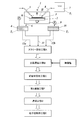
- FIG. 1 is a schematic diagram showing an example of a basic process flow of the abrasive recycling method of the present invention.
- the present invention is an abrasive recycling method in which used abrasives used in the polishing step performed before the slurry recovery step A shown in FIG. 1 are recycled as recycled abrasives.
- the polishing process using the abrasive will be explained.
- polishing process Taking the polishing of a glass substrate as an example, in the polishing process, one polishing process is generally constituted by preparation of an abrasive slurry, polishing processing, and cleaning of a polishing portion.
- the polishing machine 1 has a polishing surface plate 2 to which a polishing cloth K composed of a nonwoven fabric, a synthetic resin foam, a synthetic leather or the like is attached.
- the polishing surface plate 2 is rotatable.
- an object to be polished for example, optical glass, glass substrate for information recording medium, silicon wafer, etc.
- an object to be polished for example, optical glass, glass substrate for information recording medium, silicon wafer, etc.
- the polishing surface plate 2 is rotated.
- the slurry liquid 4 (abrasive slurry) prepared in advance is supplied from the slurry nozzle 5 via the pump P.
- Abrasive liquid after use 4 (abrasive slurry containing spent abrasive) is stored in a slurry tank T 1 through the channel 6, repeatedly circulates between the polishing machine 1 and the slurry tank T 1.
- the washing water 7 for cleaning the polishing machine 1 are stored in the washing water storage tank T 2, from the washing water ejecting nozzle 8, washed by spraying the polishing section, the cleaning liquid 10 containing an abrasive ( as abrasive slurry) containing the spent abrasive, through the pump, through the channel 9, is stored in the cleaning liquid storage tank T 3.
- the cleaning liquid reservoir T 3 is a tank for storing the cleaning water after being used in the washing (rinsing).
- the cleaning liquid reservoir T 3 is precipitated, in order to prevent agglomeration, is agitated by the constant stirring blade.
- the cleaning liquid 10 stored in the cleaning liquid storage tank T 3 is polished with abrasive particles, which are polished It is in a state containing a glass component or the like derived from an object to be polished that has been scraped off from the object 3.
- abrasive slurry is prepared by adding and dispersing abrasive powder in a concentration range of 1 to 40 mass% with respect to a solvent such as water. This abrasive slurry is circulated and supplied to the polishing machine 1 as shown in FIG.
- the particles used as the abrasive particles having an average particle size of several tens nm to several ⁇ m are used.
- a dispersant or the like to the abrasive slurry used by circulating supply, it is possible to prevent the abrasive particles from agglomerating and to maintain a dispersed state by constantly stirring with an agitator or the like. Is preferred.
- a tank for abrasive slurry is installed next to the polishing machine 1, a dispersion state is always maintained using a stirrer, etc., and a supply pump is used to circulate and supply to the polishing machine 1 It is preferable to do.
- polishing pad polishing cloth K
- the object to be polished 3 are brought into contact with each other, and the pad F and the object to be polished are applied under pressure while supplying the abrasive slurry to the contact surface.
- the object 3 is moved relative to each other.
- the used abrasive slurry referred to in the present invention is the abrasive slurry stored in the cleaning liquid storage tank T 3 and the polishing machine 1, the slurry tank T 1 and the cleaning liquid storage tank T 3 are discharged out of the polishing process system.
- the first is a washing operation with discharge abrasive slurry which is stored the cleaning liquid to the cleaning liquid reservoir T 3 comprising (rinse slurry), second is discarded after being given the number of manipulations used, the slurry it is spent abrasive slurry reserved in the tank T 1 (Life end slurry).
- a characteristic of the life end slurry is that the concentration of the glass component is higher than that of a new abrasive slurry.
- the abrasive recycling method of the present invention in which a high-purity abrasive is regenerated from an abrasive slurry containing a used abrasive and reused as a recycled abrasive is, as shown in FIG. It comprises six steps: a step B, an abrasive recovery step C, a second concentration step F, a filtration step D, and a particle size control step E.
- the second concentration step F and the particle size control step E either or both of the steps are appropriately omitted depending on the type of abrasive that is reused as the recycled abrasive, the required concentration, purity, and the like. be able to.
- the slurry recovery step A is a step of recovering an abrasive slurry containing a used abrasive.
- the recovered abrasive slurry contains an abrasive in the range of about 0.1 to 40% by mass.
- the recovered abrasive slurry may immediately proceed to the separation and concentration step B after recovery, or may be stored until a certain amount is recovered. In any case, it is preferable that the recovered abrasive slurry is constantly stirred to prevent aggregation of particles and maintain a stable dispersion state.
- the two types of abrasive slurry recovered in the slurry recovery step A are mixed and prepared as a mother liquor, and then treated in the separation and concentration step B or recovered in the slurry recovery step A.
- the rinse slurry and the life end slurry may be treated in the separation and concentration step B as independent mother liquors.
- Separation and concentration step C is a step of adding a metal salt containing an alkaline earth metal element as an inorganic salt to the recovered abrasive slurry to aggregate the abrasive, and separating and concentrating the abrasive from the mother liquor. .
- the collected used abrasive slurry is in a state in which glass components derived from the object to be polished are mixed. Further, since the concentration is lowered due to the mixing of the washing water, it is necessary to separate the glass component and the like and concentrate the abrasive component in order to use the recovered abrasive again in the polishing process.
- the separation and concentration step B adds an alkaline earth metal salt as an inorganic salt to the abrasive slurry (mother liquor) recovered in the slurry recovery step A, particularly without adding a pH adjuster,
- the abrasive is separated from the mother liquor and concentrated. This allows only the abrasive component to coagulate and precipitate, and then allows the majority of the glass component to be present in the supernatant to separate the coagulated precipitate, thereby separating the abrasive component from the glass component and concentrating the abrasive slurry. Can be performed simultaneously.
- alkaline earth metal salt examples include calcium salts, strontium salts, and barium salts. Furthermore, in the present invention, elements belonging to Group 2 of the periodic table are also broadly defined. , Defined as an alkaline earth metal. Therefore, beryllium salts and magnesium salts also belong to the alkaline earth metal salts referred to in the present invention.
- the alkaline earth metal salt according to the present invention is preferably in the form of a halide, sulfate, carbonate, acetate or the like having high solubility in water.
- the alkaline earth metal salt applicable to the present invention a magnesium salt having a small pH change of the solution upon addition is preferable.
- the magnesium salt is not limited as long as it functions as an electrolyte, but magnesium chloride, magnesium bromide, magnesium iodide, magnesium sulfate, magnesium acetate and the like are preferable from the viewpoint of high solubility in water.
- Magnesium chloride and magnesium sulfate are particularly preferred because the pH change is small and the settled abrasive and waste liquid can be easily treated.
- the inorganic salt to be added may be supplied directly to the abrasive slurry (mother liquid) or after being dissolved in a solvent such as water and then added to the abrasive slurry (mother liquid). Although it is good, it is preferable to add in the state dissolved in the solvent so that it may become a uniform state after adding to the abrasive slurry.
- a preferable concentration of the inorganic salt is an aqueous solution having a concentration range of 0.5 to 50% by mass.
- the concentration is in the range of 10 to 40% by mass.
- the temperature at which the inorganic salt is added is not less than the temperature at which the recovered abrasive slurry is frozen and can be appropriately selected as long as it is in the range up to 90 ° C. From the viewpoint of efficiently performing the separation, it is preferably in the range of 10 to 40 ° C, more preferably in the range of 15 to 35 ° C.
- Addition rate of inorganic salt The addition rate of the inorganic salt to the abrasive slurry (mother liquor) is uniform as the inorganic salt concentration in the recovered abrasive slurry without locally generating a high concentration region. It is preferable to add such that.
- the addition amount per minute is preferably 20% by mass or less of the total addition amount, and more preferably 10% by mass or less.
- the pH value of the abrasive slurry recovered in advance is not adjusted.
- the pH value of the recovered abrasive slurry is slightly alkaline because it contains a glass component and is in the range of less than 8 to 10.
- the pH value of the mother liquor is 10. It is preferable to perform separation and concentration under a condition of less than 0.
- the pH value is a value measured at 25 ° C. using a Lacom Tester desktop pH meter (pH 1500, manufactured by As One Co., Ltd.).
- the pH value at the time of inorganic salt addition means the pH value immediately after the addition of the inorganic salt is completed.
- stirring is preferably continued for at least 10 minutes, more preferably 30 minutes or more. Aggregation of the abrasive particles starts simultaneously with the addition of the inorganic salt, but maintaining the stirring state makes the aggregation state uniform throughout the system, narrowing the particle size distribution of the concentrate, and facilitating subsequent separation.
- the abrasive recovery process C is a process of recovering the concentrate by solid-liquid separation of the abrasive that has been separated in the separation and concentration process B and concentrated.
- a general solid-liquid separation method of the concentrate can be employed as a method for separating the concentrated abrasive and the supernatant liquid from the addition of the inorganic salt. That is, a method of separating only the supernatant by performing natural sedimentation, or a method of forcibly separating using a mechanical method such as a centrifuge can be applied. From the viewpoint of obtaining a high-purity recycled abrasive without mixing impurities such as a glass component derived from the object to be polished 3 as much as possible into the concentrated concentrate, it is preferable to apply natural sedimentation as the concentration method.
- the concentrate has a higher specific gravity than the abrasive slurry recovered in the recovery step A. It will be concentrated.
- This concentrate contains used abrasives at a concentration higher than the recovered abrasive slurry.
- the second concentration step F is a step of separating the concentrate containing the used abrasive from the abrasive slurry recovered in the abrasive recovery step C.
- separation by a natural sedimentation method is applied in order to prevent contamination of impurities. Since this concentrate is mixed in a state where a part of the supernatant is not separated and removed, the supernatant mixed in the concentrate is further removed as a second concentration step F by filtration. Then, a treatment for further increasing the purity of the collected used abrasive is applied.
- the second concentration step F is a step desirably applied in order to obtain a recycled abrasive with higher purity, but is appropriately omitted depending on the type of abrasive to be recycled, the required concentration, and the like. be able to.
- the filtration filter used in the second concentration step F is not particularly limited, and examples thereof include a hollow fiber filter, a metal filter, a bobbin filter, a ceramic filter, and a roll-type polypropylene filter. Among these, it is preferable to use a ceramic filter.
- a ceramic filter applicable to the present invention for example, a ceramic filter manufactured by TAMI, France, a ceramic filter manufactured by Noritake, a ceramic filter manufactured by NGK (for example, Ceralek DPF, Sepilt, etc.) can be used.
- the magnetic filter used in the filtration step D includes a filter portion made of a material such as a permanent magnet or an electromagnet, for example.
- a filter portion made of a material such as a permanent magnet or an electromagnet
- the metal element particles which are the impurities, are attracted by the magnetic force of the filter and are removed from the abrasive.
- an electromagnet is used as the material for the magnetic filter, the magnetic force can be easily controlled by turning on / off the current.
- the specific shape of the magnetic filter is not particularly limited.
- the magnetic filter may be formed in a rod shape along the flow path through which the solution or concentrate containing the abrasive passes, or the solution or concentrate flows. You may form in the rod shape along the orthogonal direction of a direction.
- One or more rod-like magnetic filters may be formed in the flow path.
- the flow path through which the solution or concentrate passes may have one or a plurality of large-diameter portions (reservoir portions), and may include a rod-shaped magnetic filter in the reentrant portion.
- the shape of the magnetic filter can be changed as appropriate according to the type and viscosity of the abrasive slurry containing the used abrasive.
- the concentrate obtained by agglomerating and collecting the abrasive particles using an inorganic salt or the like is a lump as secondary particles in the state as it is, and in order to reuse, the aggregated abrasive particles are decomposed,
- a particle diameter control step E it is preferable to incorporate a particle diameter control step E at the end.
- Particle size control step E is a step in which the abrasive component obtained in the filtration step D is redispersed and the particle size is adjusted so as to have a particle size distribution equivalent to that of the abrasive slurry before processing.
- a method for redispersing the aggregated abrasive particles a) a method of adding water to lower the concentration of inorganic ions in the treatment liquid, and b) an abrasive by adding a metal separating agent (also referred to as a dispersant).
- a metal separating agent also referred to as a dispersant.
- the amount added is appropriately selected according to the volume of the concentrated slurry, and is generally 5 to 50% by volume, preferably 10 to 40% by volume of the concentrated slurry.
- the metal separating agent a polycarboxylic acid-based polymer dispersing agent having a carboxy group is preferably exemplified, and an acrylic acid-maleic acid copolymer is particularly preferable.
- Specific examples of the metal separating agent (dispersant) include Polyty A550 (manufactured by Lion Corporation). The addition amount of the metal separating agent (dispersant) is 0.01 to 5% by volume with respect to the concentrated slurry.
- an ultrasonic disperser a medium stirring mill such as a sand mill or a bead mill can be applied, and it is particularly preferable to use an ultrasonic disperser.
- ultrasonic disperser examples are commercially available from SMT Co., Ltd., Ginsen Co., Ltd., Taitec Co., Ltd., BRANSON, Kinematica Co., Ltd., Nippon Seiki Seisakusho Co., Ltd., and SMT UDU Co., Ltd. -1, UH-600MC, Ginsen GSD600CVP, Nippon Seiki Seisakusho RUS600TCVP, etc. can be used.
- the frequency of the ultrasonic wave is not particularly limited.
- Examples of the circulation system that performs mechanical agitation and ultrasonic dispersion simultaneously are SMT Co., Ltd. UDU-1, UH-600MC, Ginseng Co., Ltd. GSD600RCVP, GSD1200RCVP, Nippon Seiki Seisakusho Co., Ltd. RUS600TCVP, etc. You can, but you are not limited to this.
- the particle size distribution obtained in the particle size control step E it is desirable that there is little variation with time and little variation in particle size after one day.
- the final recovered abrasive obtained through the particle size control step E contains a high-purity abrasive of 98% by mass or more, has a small variation with time in the particle size distribution, and is higher than the concentration at the time of recovery.
- the content of is preferably in the range of 0.0005 to 0.08 mass%.
- the filtration step D may be provided after the slurry recovery step A, for example, after the separation and concentration step B, the abrasive recovery step C, the second concentration step D, or The structure performed simultaneously with a process may be sufficient.
- the particle size control step E is an abrasive material regeneration in which a redispersion process is performed to change the abrasive particles from a lump as a secondary particle to a single particle (primary particle) state. Since this is the final step of the method, it is desirable to perform the filtration process by the filtration step D before the particle diameter control step E, which can remove all the metal element particles mixed in by the operation of each step.
- Slurry recovery process A In the polishing step shown in FIG. 1, after polishing the hard disk glass substrate using cerium oxide (made by CI Kasei Co., Ltd.) as an abrasive, 210 liters of a rinsing slurry containing cleaning water and used abrasive 30 liters of the life end slurry was collected, and 240 liters were collected as a recovered slurry liquid.
- This recovered slurry liquid has a specific gravity of 1.03 and contains 8.5 kg of cerium oxide.
- Second concentration step F The 2nd concentration process F processed by the filtration process using the filtration apparatus which is not illustrated.
- the concentrate recovered in the abrasive recovery step C was sent to a filtration device by a pump while being slowly stirred with a stirrer in the state of secondary particles.
- This filtration apparatus was equipped with the filtration filter, the concentrate was passed through the filtration filter, and the supernatant liquid containing a glass component was isolate
- the concentrate was circulated in the filtration apparatus for 15 minutes at a flow rate of 1.2 L / min, and concentrated and filtered until it became 1/2 of the initial liquid amount of the concentrate.
- the filter used in the second concentration step F was a ceramic filter “Cefilt” (pore diameter: 0.5 ⁇ m) manufactured by NGK.
- Filtration process D performed the process which filters and removes the particle
- Particle size control step E 12 liters of water was added to the separated concentrate. Furthermore, after adding 300 g of Polyty A550 (manufactured by Lion Corporation) as a metal separating agent (polymer dispersing agent) and stirring for 30 minutes, the concentrate was dispersed using an ultrasonic disperser (manufactured by BRANSON). I unraveled it.
- Polyty A550 manufactured by Lion Corporation
- an ultrasonic disperser manufactured by BRANSON
- filtration was performed with a 10-micron membrane filter to obtain a regenerated abrasive 1 containing regenerated cerium oxide.
- Example 3 In the preparation of the regenerated abrasive 1, a regenerated abrasive 3 was obtained in the same manner except that the liquid feeding speed in the filtration step D was changed to 2.0 L / min.
- Recycled abrasive 4 was obtained in the same manner as in the preparation of recycled abrasive 1 except that the magnetic force of the magnetic filter in filtration step D was changed to 5000 Tesla.
- Recycled abrasive 6 was obtained in the same manner as in the preparation of recycled abrasive 3 except that the magnetic force of the magnetic filter in filtration step D was changed to 5000 Tesla.
- Recycled abrasive 7 was obtained in the same manner as in the preparation of recycled abrasive 2 except that the magnetic force of the magnetic filter in filtration step D was changed to 10,000 Tesla.
- Regenerated abrasive 8 was obtained in the same manner as in the preparation of the regenerated abrasive 3 except that the magnetic force of the magnetic filter in the filtration step D was changed to 10,000 Tesla.
- Recycled abrasive 10 was obtained in the same manner as in the preparation of recycled abrasive 2 except that the magnetic force of the magnetic filter in filtration step D was changed to 20000 Tesla.
- Table 1 shows the results obtained by the above evaluation.
- Examples 1 to 10 clearly have fewer scratches after processing than Comparative Example 1 in which the treatment by the filtration step D using a magnetic filter was not performed. Further, in Examples 1 to 10, it is considered that a slight amount of metal element particles remained in the polishing material due to an increase in the liquid feeding speed, and the number of scratches increased. Moreover, about Examples 1-10, it turns out that the number of the cracks after a process is reducing by strengthening the magnetic force of a magnetic filter compared with the Example of the same liquid feeding speed.
- the abrasive is at least one selected from cerium oxide, diamond, boron nitride, silicon carbide, alumina, alumina zirconia, and zirconium oxide, and has been used.
- the polishing material is regenerated from the abrasive slurry containing the used abrasive material through the filtering step D to be removed, and the process D includes the steps A to C. After either the step or step B or step C simultaneously performed.
- impurities such as metal element particles mixed in the process of polishing the object to be polished and metal element particles mixed from the apparatus to be used can be removed, and metal elements having a particle diameter smaller than that of the abrasive particles can be removed. Since even particles can be removed, a higher-purity recycled abrasive can be obtained from an abrasive slurry containing a used abrasive.
- the magnetic filter is made of a permanent magnet material or an electromagnet material, the metal element particles can be removed regardless of the particle diameter of the abrasive particles. Further, when an electromagnet material is used, the magnetic force can be easily controlled by turning on / off the current.
- the particle diameter control process E which adjusts the particle diameter of the collect
- the recovered abrasive is filtered and subjected to a second concentration process F for secondary concentration, so that it is higher.
- a recycled abrasive having an abrasive concentration can be obtained.
- the metal salt containing the alkaline earth metal element used in the separation and concentration step B is a magnesium salt, the pH change of the solution due to the addition is small, and the settled abrasive and waste liquid can be easily treated.
- the abrasive recovery method in the abrasive recovery step C is a decantation separation method by natural sedimentation, high purity is achieved without mixing impurities such as glass components derived from the object to be polished into the concentrated concentrate as much as possible. The regenerated abrasive can be obtained.
- the magnetic force and the liquid feeding speed in the filtration step D are examples, and can be appropriately changed according to the type, concentration, viscosity, and the like of the abrasive.
- regenerating method of this invention although it was set as the structure which performs the filtration process by the filtration process D once, according to the kind etc. of abrasives, it is good also as a structure performed several times.
- the present invention can be used in the field of recycling abrasives used in the manufacturing process of glass products, semiconductor devices, crystal oscillators and the like.
Landscapes
- Engineering & Computer Science (AREA)
- Mechanical Engineering (AREA)
- Chemical & Material Sciences (AREA)
- Organic Chemistry (AREA)
- Grinding-Machine Dressing And Accessory Apparatuses (AREA)
- Mechanical Treatment Of Semiconductor (AREA)
Description
特許文献1の方法では、被研磨物由来の成分と研磨材を分離して、研磨材を回収することができるが、混入した不純物である金属元素の粒子を取り除くことができない。
使用済みの研磨材を含む研磨材スラリーから、研磨材を再生する研磨材再生方法であって、当該研磨材が、下記研磨材群から選ばれる少なくとも一種であり、かつ下記工程A~Dを経て研磨材を再生するとともに、工程Dが工程A~工程Cのいずれかの工程の後又は工程B若しくは工程Cと同時に行われることを特徴とする。
工程A:使用済みの研磨材を含む研磨材スラリーを回収するスラリー回収工程A
工程B:当該回収された研磨材スラリーに対し、無機塩としてアルカリ土類金属元素を含む金属塩を添加して研磨材を凝集させ、当該研磨材を母液より分離して濃縮する分離濃縮工程B
工程C:当該分離され、濃縮された研磨材を固液分離して回収する研磨材回収工程C
工程D:マグネティックフィルターにより研磨材スラリーに混入する金属元素の粒子を濾過して取り除く濾過工程D
研磨材群:酸化セリウム、ダイヤモンド、窒化ホウ素、炭化ケイ素、アルミナ、アルミナジルコニア、酸化ジルコニウム
前記マグネティックフィルターは、永久磁石材料又は電磁石材料により構成されていることを特徴する。
工程E:前記回収された研磨材の粒子径を調整する粒子径制御工程Eを備え、
前記濾過工程Dは、前記粒子径制御工程Eの直前に行われることを特徴とする。
工程F:前記研磨材回収工程Cの後であって、前記粒子径制御工程Eの前に、前記回収された研磨材に対し濾過処理を施して2次濃縮を行う第2濃縮工程Fを備えることを特徴とする。
前記分離濃縮工程Bで用いるアルカリ土類金属元素を含む金属塩が、マグネシウム塩であることを特徴とする。
前記研磨材回収工程Cにおける研磨材の回収方法が、自然沈降によるデカンテーション分離法であることを特徴とする。
一般に、光学ガラスや半導体基板等の研磨材としては、ベンガラ(αFe2O3)、酸化セリウム、酸化アルミニウム、酸化マンガン、酸化ジルコニウム、コロイダルシリカ等の微粒子を水や油に分散させてスラリー状にしたものが用いられているが、本発明の研磨材再生方法では、半導体基板の表面やガラスの研磨加工において、高精度に平坦性を維持しつつ、十分な加工速度を得るために、物理的な作用と化学的な作用の両方で研磨を行う、化学機械研磨(CMP)への適用が可能な酸化セリウム、ダイヤモンド、窒化ホウ素、炭化ケイ素、アルミナ、アルミナジルコニア及び酸化ジルコニウムから選ばれる少なくとも1種の研磨材の回収に適用することを特徴とする。
図1は、本発明の研磨材再生方法の基本的な工程フローの一例を示す模式図である。
本発明は、図1で示すスラリー回収工程Aの前に行われる研磨工程で使用された使用済み研磨材を、再生研磨材として再生する研磨材再生方法である。研磨材の再生方法を説明する前に、研磨材による研磨工程について説明する。
ガラス基板の研磨を例にとると、研磨工程では、研磨材スラリーの調製、研磨加工、研磨部の洗浄で一つの研磨工程を構成しているのが一般的である。
図1に示した研磨工程の全体の流れとしては、研磨機1は、不織布、合成樹脂発泡体、合成皮革などから構成される研磨布Kを貼付した研磨定盤2を有しており、この研磨定盤2は回転可能となっている。研磨作業時には、ケイ素を主成分とする被研磨物(例えば、光学ガラス、情報記録媒体用ガラス基板、シリコンウェハー等)3を、保持具Hを用いて、所定の押圧力Nで上記研磨定盤2に押し付けながら、研磨定盤2を回転させる。同時に、スラリーノズル5から、ポンプPを介して予め調製した研磨材液4(研磨材スラリー)を供給する。使用後の研磨材液4(使用済みの研磨材を含む研磨材スラリー)は、流路6を通じてスラリー槽T1に貯留され、研磨機1とスラリー槽T1との間を繰り返し循環する。
(1)研磨材スラリーの調製
研磨材の粉体を水等の溶媒に対して1~40質量%の濃度範囲となるように添加、分散させて研磨材スラリーを調製する。この研磨材スラリーは、研磨機1に対して、図1で示したように循環供給して使用される。研磨材として使用される粒子は、平均粒子径が数十nmから数μmの大きさの粒子が使用される。
図1に示すように、研磨パット(研磨布K)と被研磨物3を接触させ、接触面に対して研磨材スラリーを供給しながら、加圧条件下でパットFと被研磨物3を相対運動させる。
研磨された直後の被研磨物3及び研磨機1には大量の研磨材が付着している。そのため、研磨した後に研磨材スラリーの代わりに水等を供給し、被研磨物3及び研磨機1に付着した研磨材の洗浄が行われる。この際に、研磨材を含む洗浄液10は系外9に排出される。
本発明でいう使用済み研磨材スラリーとは、洗浄液貯蔵槽T3に貯蔵される研磨材スラリー及び研磨機1、スラリー槽T1及び洗浄液貯蔵槽T3から構成される研磨工程の系外に排出される研磨材スラリーであって、主として以下の二種類がある。
使用済みの研磨材を含む研磨材スラリーから高純度の研磨材を再生し、再生研磨材として再利用する本発明の研磨材再生方法は、図1に示すように、スラリー回収工程A、分離濃縮工程B、研磨材回収工程C、第2濃縮工程F、濾過工程D及び粒子径制御工程Eの6つの工程を備える。なお、第2濃縮工程F及び粒子径制御工程Eは、再生研磨材として再利用する研磨材の種類、必要とされる濃度、純度等に応じて、どちらか一方又は両方の工程を適宜省略することができる。
スラリー回収工程Aは、使用済みの研磨材を含む研磨材スラリーを回収する工程である。なお、回収された研磨材スラリーには、おおむね0.1~40質量%の範囲で研磨材が含まれる。
分離濃縮工程Cは、回収した研磨材スラリーに対し、無機塩としてアルカリ土類金属元素を含む金属塩を添加して研磨材を凝集させ、当該研磨材を母液より分離して濃縮する工程である。回収された使用済み研磨材スラリーは、被研磨物由来のガラス成分等が混入した状態にある。また、洗浄水の混入により濃度が低下しており、回収した研磨材を研磨加工に再度使用するためには、ガラス成分等の分離と、研磨材成分の濃縮化を行う必要がある。
本発明に係るアルカリ土類金属塩としては、例えば、カルシウム塩、ストロンチウム塩、バリウム塩を挙げることができるが、更には、本発明においては、広義として周期律表の第2族に属する元素も、アルカリ土類金属であると定義する。したがって、ベリリウム塩、マグネシウム塩も本発明でいうアルカリ土類金属塩に属する。
次いで、本発明に係る無機塩の研磨材スラリー(母液)に対する添加方法を説明する。
添加する無機塩は、粉体を研磨材スラリー(母液)に直接供給しても良いし、水等の溶媒に溶解させてから研磨材スラリー(母液)に添加してもよいが、研磨材スラリーに添加した後に均一な状態になるように、溶媒に溶解させた状態で添加することが好ましい。
無機塩を添加する際の温度は、回収した研磨材スラリーが凍結する温度以上であって、90℃までの範囲であれば適宜選択することができるが、ガラス成分との分離を効率的に行う観点からは、10~40℃の範囲内であることが好ましく、15~35℃の範囲内であることがより好ましい。
無機塩の研磨材スラリー(母液)に対する添加速度としては、回収した研磨材スラリー中での無機塩濃度として、局部的に高濃度領域が発生することなく、均一になるように添加することが好ましい。1分間当たりの添加量が全添加量の20質量%以下であることが好ましく、10質量%以下であることがより好ましい。
本発明の研磨材再生方法においては、分離濃縮工程Bで無機塩を添加する際に、あらかじめ回収した研磨材スラリーのpH値を調整しないことが好ましい態様である。一般に、回収した研磨材スラリーのpH値は、ガラス成分を含有しているためややアルカリ性を示し、8~10未満の範囲であり、本発明においては、母液の25℃換算のpH値が10.0未満の条件で分離濃縮を行うことが好ましい。これは、pH値が10以上である場合は、被研磨物3であるガラス成分が凝集しやすく添加剤の添加により研磨材とともに凝集・沈降してしまうが、pH値が10未満であれば、溶解度の差が大きいため、2次粒子の状態に凝集した研磨材成分にガラス成分が取り込まれることが少ないためである。
無機塩を添加した後、少なくとも10分以上撹拌を継続することが好ましく、より好ましくは30分以上である。無機塩を添加すると同時に研磨材粒子の凝集が開始されるが、撹拌状態を維持することで凝集状態が系全体で均一となり濃縮物の粒度分布が狭くなり、その後の分離が容易となる。
研磨材回収工程Cは、分離濃縮工程Bにて分離され、濃縮された研磨材を固液分離して濃縮物を回収する工程である。
第2濃縮工程Fは、研磨材回収工程Cで回収した研磨材スラリーから使用済み研磨材を含む濃縮物を分離する工程である。第2濃縮工程Fで用いられる分離方法には、不純物の混入を防止するため自然沈降法による分離を適用している。この濃縮物には、上澄み液の一部が分離・除去されていない状態で混入しているため、更に、第2濃縮工程Fとして、濾過処理により濃縮物に混入している上澄み液を除去して、回収された使用済み研磨材の純度をより一層高くする処理を施す。この濾過処理は、分離濃縮工程Bより前に実施することも可能ではあるが、回収スラリー中に存在するガラス成分による目詰まりを防ぐため、分離濃縮工程B及び研磨材回収工程Cにおいて一定量のガラス成分等を除去した後に、第2濃縮工程Fを適用することが、生産効率の観点から好ましい。また、第2濃縮工程Fは、より純度の高い再生研磨材を得るために、適用することが望ましい工程であるが、再生する研磨材の種類、必要とされる濃度等に応じて適宜省略することができる。
本発明の研磨材再生方法においては、第2濃縮工程Fの後に、マグネティックフィルターにより、使用済みの研磨材を含む研磨材スラリーに含まれる金属元素の粒子、例えば、分離濃縮工程Bにおいて添加されたアルカリ土類金属塩により混入した金属元素の粒子等、各工程における操作、装置等から混入した金属元素の粒子を濾過して取り除く濾過工程Dを備える。
また、マグネティックフィルターの具体的な形状は、特に限定されないが、例えば、研磨材を含む溶液又は濃縮物が通過する流路に沿って棒状に形成されていてもよいし、溶液又は濃縮物が流れる方向の直交方向に沿って棒状に形成されていてもよい。また、棒状のマグネティックフィルターは、流路内に1つ又は複数形成されていてもよい。また、溶液又は濃縮物が通過する流路は、径の大きい部分(たまり部分)を1つ又は複数有していてもよく、たまり部分に棒状のマグネティックフィルターを備えていてもよい。マグネティックフィルターの形状は、使用済みの研磨材を含む研磨材スラリーの種類、粘度等に応じて適宜変更することができる。
本発明の研磨材再生方法においては、上記各工程を経て回収した使用済みの研磨材を再利用するため、最終工程として、2次粒子状態で凝集している研磨材粒子を解膠して1次粒子状態の粒子径分布にする粒子径制御工程Eを備えてもよい。
上記粒子径制御工程Eを経て得られる最終的な回収研磨材は、98質量%以上の高純度の研磨材を含有し、粒度分布の経時変動が小さく、回収した時の濃度より高く、無機塩の含有量としては、0.0005~0.08質量%の範囲であることが好ましい。
〔再生研磨材1の調製:実施例1〕
以下の工程に従って、研磨材として酸化セリウムを用いた再生研磨材1を調製した。なお、特に断りがない限りは、研磨材再生工程は、基本的には、25℃、55%RHの条件下で行った。このとき、溶液等の温度も25℃である。
図1に記載の研磨工程で、研磨材として酸化セリウム(シーアイ化成社製)を用いてハードディスク用ガラス基板の研磨加工を行った後、洗浄水を含むリンススラリーを210リットル、使用済み研磨材を含むライフエンドスラリーを30リットル回収し、回収スラリー液として240リットルとした。この回収スラリー液は比重1.03であり、8.5kgの酸化セリウムが含まれている。
次いで、この回収スラリー液を酸化セリウムが沈降しない程度に撹拌しながら、無機塩として塩化マグネシウムの10質量%水溶液を2.0リットル、10分間かけて添加した。塩化マグネシウムを添加した直後の25℃換算のpH値は8.60であった。
上記の状態で30分撹拌を継続した後、45分間静置して、自然沈降法により、上澄み液と濃縮物とを沈降・分離した。45分後に、排水ポンプを用いて、上澄み液を排出して、濃縮物を固液分離して回収した。回収した濃縮物は60リットルであった。
第2濃縮工程Fは、図示しない濾過装置を用いる濾過処理により処理を行った。
濾過工程Dは、マグネティックフィルターにより研磨材に混入する金属元素の粒子を濾過して取り除く処理を行った。
具体的には、濾過工程Dは、マグネティックフィルターの磁力を3000Tesla、濾過する濃縮物の送液速度を0.5L/minで濾過処理を行った。
分離した濃縮物に水12リットルを添加した。さらに、金属分離剤(高分子分散剤)としてポリティーA550(ライオン(株)製)を300g添加し、30分撹拌した後、超音波分散機(BRANSON社製)を用いて、濃縮物を分散して解きほぐした。
上記再生研磨材1の調製において、濾過工程Dにおける送液速度を1.0L/minに変更した以外は同様にして再生研磨材2を得た。
上記再生研磨材1の調製において、濾過工程Dにおける送液速度を2.0L/minに変更した以外は同様にして再生研磨材3を得た。
上記再生研磨材1の調製において、濾過工程Dにおけるマグネティックフィルターの磁力を5000Teslaに変更した以外は同様にして再生研磨材4を得た。
上記再生研磨材2の調製において、濾過工程Dにおけるマグネティックフィルターの磁力を5000Teslaに変更した以外は同様にして再生研磨材5を得た。
上記再生研磨材3の調製において、濾過工程Dにおけるマグネティックフィルターの磁力を5000Teslaに変更した以外は同様にして再生研磨材6を得た。
上記再生研磨材2の調製において、濾過工程Dにおけるマグネティックフィルターの磁力を10000Teslaに変更した以外は同様にして再生研磨材7を得た。
上記再生研磨材3の調製において、濾過工程Dにおけるマグネティックフィルターの磁力を10000Teslaに変更した以外は同様にして再生研磨材8を得た。
上記再生研磨材1の調製において、濾過工程Dにおけるマグネティックフィルターの磁力を20000Teslaに変更した以外は同様にして再生研磨材9を得た。
上記再生研磨材2の調製において、濾過工程Dにおけるマグネティックフィルターの磁力を20000Teslaに変更した以外は同様にして再生研磨材10を得た。
上記再生研磨材2の調製において、濾過工程Dによる濾過処理を行わなかった以外は同様にして再生研磨材11を得た。
〔加工キズ〕
実施例1から10及び比較例1について、被研磨物3である外径65mm、内径20mmのドーナツ状ガラス基板1枚当たりに存在する0.2μm以上の傷(キズ)の個数を調べた。

また、濾過工程Dにおける磁力、送液速度は、一例であって、研磨材の種類、濃度、粘度等に合わせて適宜変更することができる。また、本発明の研磨材再生方法において、濾過工程Dによる濾過処理を1度行う構成としたが、研磨材の種類等に応じて、複数回行う構成としてもよい。
2 研磨定盤
3 被研磨物
4 研磨材液
5 スラリーノズル
7 洗浄水
8 洗浄水噴射ノズル
10 研磨材を含む洗浄液
F 濾過濃縮部
K 研磨布
T1 スラリー槽
T2 洗浄水貯蔵槽
T3 洗浄液貯蔵槽
Claims (6)
- 使用済みの研磨材を含む研磨材スラリーから、研磨材を再生する研磨材再生方法であって、当該研磨材が、下記研磨材群から選ばれる少なくとも一種であり、かつ下記工程A~Dを経て研磨材を再生するとともに、工程Dが工程A~工程Cのいずれかの工程の後又は工程B若しくは工程Cと同時に行われることを特徴とする研磨材再生方法。
工程A:使用済みの研磨材を含む研磨材スラリーを回収するスラリー回収工程A
工程B:当該回収された研磨材スラリーに対し、無機塩としてアルカリ土類金属元素を含む金属塩を添加して研磨材を凝集させ、当該研磨材を母液より分離して濃縮する分離濃縮工程B
工程C:当該分離され、濃縮された研磨材を固液分離して回収する研磨材回収工程C
工程D:マグネティックフィルターにより研磨材スラリーに混入する金属元素の粒子を濾過して取り除く濾過工程D
研磨材群:酸化セリウム、ダイヤモンド、窒化ホウ素、炭化ケイ素、アルミナ、アルミナジルコニア、酸化ジルコニウム - 前記マグネティックフィルターは、永久磁石材料又は電磁石材料により構成されていることを特徴する請求項1に記載の研磨材再生方法。
- 工程E:前記回収された研磨材の粒子径を調整する粒子径制御工程Eを備え、
前記濾過工程Dは、前記粒子径制御工程Eの直前に行われることを特徴とする請求項1又は2に記載の研磨材再生方法。 - 工程F:前記研磨材回収工程Cの後であって、前記粒子径制御工程Eの前に、前記回収された研磨材に対し濾過処理を施して2次濃縮を行う第2濃縮工程Fを備えることを特徴とする請求項3に記載の研磨材再生方法。
- 前記分離濃縮工程Bで用いるアルカリ土類金属元素を含む金属塩が、マグネシウム塩であることを特徴とする請求項1から4のいずれか一項に記載の研磨材再生方法。
- 前記研磨材回収工程Cにおける研磨材の回収方法が、自然沈降によるデカンテーション分離法であることを特徴とする請求項1から5のいずれか一項に記載の研磨材再生方法。
Priority Applications (4)
| Application Number | Priority Date | Filing Date | Title |
|---|---|---|---|
| KR20157000679A KR20150030237A (ko) | 2012-07-25 | 2013-07-24 | 연마재 재생 방법 |
| US14/417,302 US20150210890A1 (en) | 2012-07-25 | 2013-07-24 | Polishing-Material Reclamation Method |
| CN201380039008.2A CN104507639A (zh) | 2012-07-25 | 2013-07-24 | 研磨材料再生方法 |
| JP2014526971A JP6406010B2 (ja) | 2012-07-25 | 2013-07-24 | 研磨材再生方法 |
Applications Claiming Priority (2)
| Application Number | Priority Date | Filing Date | Title |
|---|---|---|---|
| JP2012164825 | 2012-07-25 | ||
| JP2012-164825 | 2012-07-25 |
Publications (1)
| Publication Number | Publication Date |
|---|---|
| WO2014017534A1 true WO2014017534A1 (ja) | 2014-01-30 |
Family
ID=49997343
Family Applications (1)
| Application Number | Title | Priority Date | Filing Date |
|---|---|---|---|
| PCT/JP2013/070034 Ceased WO2014017534A1 (ja) | 2012-07-25 | 2013-07-24 | 研磨材再生方法 |
Country Status (5)
| Country | Link |
|---|---|
| US (1) | US20150210890A1 (ja) |
| JP (1) | JP6406010B2 (ja) |
| KR (1) | KR20150030237A (ja) |
| CN (2) | CN110065006A (ja) |
| WO (1) | WO2014017534A1 (ja) |
Cited By (1)
| Publication number | Priority date | Publication date | Assignee | Title |
|---|---|---|---|---|
| JP7481761B2 (ja) | 2022-10-04 | 2024-05-13 | 株式会社Mfcテクノロジー | Cmp用セリアスラリー再生方法 |
Families Citing this family (7)
| Publication number | Priority date | Publication date | Assignee | Title |
|---|---|---|---|---|
| SG11201404444TA (en) * | 2012-02-17 | 2014-10-30 | Konica Minolta Inc | Abrasive regeneration method |
| TWI546158B (zh) * | 2013-12-20 | 2016-08-21 | 中國砂輪企業股份有限公司 | 低磁性化學機械研磨修整器 |
| JP7003986B2 (ja) * | 2017-03-23 | 2022-01-21 | 住友電気工業株式会社 | 研削液の再生装置及び研削液の再生方法 |
| US11240773B2 (en) | 2018-12-07 | 2022-02-01 | Google Llc | Managing doppler and framing impacts in networks |
| CN112010300B (zh) * | 2019-05-31 | 2022-05-20 | 洛阳阿特斯光伏科技有限公司 | 一种处理含磨粒的废料的方法 |
| CN115256127A (zh) * | 2022-07-27 | 2022-11-01 | 深圳远荣智能制造股份有限公司 | 一种笔记本外壳自动化打磨生产系统 |
| CN120134096B (zh) * | 2025-04-27 | 2026-01-06 | 江苏冠华精密工业股份有限公司 | 一种高精度金属磨削装置及其方法 |
Citations (3)
| Publication number | Priority date | Publication date | Assignee | Title |
|---|---|---|---|---|
| JP2000254659A (ja) * | 1999-03-12 | 2000-09-19 | Kurita Water Ind Ltd | Cmp排液の処理方法 |
| JP2003266309A (ja) * | 2002-03-12 | 2003-09-24 | Komatsu Electronic Metals Co Ltd | ラッピングスラリ液再生装置および方法 |
| JP2011041876A (ja) * | 2009-08-19 | 2011-03-03 | Noritake Co Ltd | 分級装置 |
Family Cites Families (20)
| Publication number | Priority date | Publication date | Assignee | Title |
|---|---|---|---|---|
| JP2501300Y2 (ja) * | 1989-12-13 | 1996-06-12 | マツダ株式会社 | 水研砥粒の再生装置 |
| US5664990A (en) * | 1996-07-29 | 1997-09-09 | Integrated Process Equipment Corp. | Slurry recycling in CMP apparatus |
| JP3134189B2 (ja) * | 1997-09-18 | 2001-02-13 | 福島県 | 研磨材の回収方法 |
| US6238450B1 (en) * | 1999-06-16 | 2001-05-29 | Saint-Gobain Industrial Ceramics, Inc. | Ceria powder |
| JP3219744B2 (ja) * | 1999-07-26 | 2001-10-15 | コナミ株式会社 | ビデオゲーム装置、ビデオゲーム表示方法およびビデオゲーム表示プログラムが記録された可読記録媒体 |
| JP2001308043A (ja) * | 2000-04-26 | 2001-11-02 | Hitachi Chem Co Ltd | Cmp研磨剤及び基板の研磨方法 |
| JP3798237B2 (ja) * | 2000-10-27 | 2006-07-19 | Ntn株式会社 | 研削スラッジの固形化物製造装置 |
| US6623355B2 (en) * | 2000-11-07 | 2003-09-23 | Micell Technologies, Inc. | Methods, apparatus and slurries for chemical mechanical planarization |
| JP2004290855A (ja) * | 2003-03-27 | 2004-10-21 | Sumitomo Bakelite Co Ltd | 不純物の除去装置 |
| JP2004306210A (ja) * | 2003-04-08 | 2004-11-04 | Speedfam Co Ltd | ガラス研磨における排出水中の酸化セリウム系研磨剤と水を再利用するための処理方法とその処理装置 |
| US7201839B2 (en) * | 2003-12-12 | 2007-04-10 | Conocophillips Company | Desulfurization and novel compositions for same |
| ITRM20050329A1 (it) * | 2005-06-24 | 2006-12-25 | Guido Fragiacomo | Procedimento per il trattamento di sospensioni abrasive esauste per il recupero delle loro componenti riciclabili e relativo impianto. |
| JP4630240B2 (ja) * | 2005-08-24 | 2011-02-09 | 株式会社トクヤマ | シリコン粉含有排水の処理方法 |
| JPWO2007105714A1 (ja) * | 2006-03-13 | 2009-07-30 | 昭和電工株式会社 | 希土類フッ化物を含有する組成物から希土類元素を回収する方法 |
| JP4729428B2 (ja) * | 2006-04-07 | 2011-07-20 | Agcセイミケミカル株式会社 | セリウム系研磨剤の再生方法 |
| JP2008188723A (ja) * | 2007-02-06 | 2008-08-21 | Mitsubishi Electric Corp | 使用済スラリーのリサイクル方法 |
| JP5090191B2 (ja) * | 2008-01-24 | 2012-12-05 | 三和油化工業株式会社 | 遊離砥粒スラリー廃液からの分散媒の回収方法 |
| US20110059002A1 (en) * | 2008-04-11 | 2011-03-10 | John Allan Fallavollita | Methods and apparatus for recovery of silicon and silicon carbide from spent wafer-sawing slurry |
| US20110017230A1 (en) * | 2009-07-27 | 2011-01-27 | Memc Electronic Materials, Inc. | Method and System for Processing Abrasive Slurry |
| KR101245276B1 (ko) * | 2010-03-12 | 2013-03-19 | 주식회사 엘지화학 | 산화세륨 연마재의 재생 방법 |
-
2013
- 2013-07-24 JP JP2014526971A patent/JP6406010B2/ja active Active
- 2013-07-24 KR KR20157000679A patent/KR20150030237A/ko not_active Ceased
- 2013-07-24 CN CN201910284971.6A patent/CN110065006A/zh active Pending
- 2013-07-24 WO PCT/JP2013/070034 patent/WO2014017534A1/ja not_active Ceased
- 2013-07-24 CN CN201380039008.2A patent/CN104507639A/zh active Pending
- 2013-07-24 US US14/417,302 patent/US20150210890A1/en not_active Abandoned
Patent Citations (3)
| Publication number | Priority date | Publication date | Assignee | Title |
|---|---|---|---|---|
| JP2000254659A (ja) * | 1999-03-12 | 2000-09-19 | Kurita Water Ind Ltd | Cmp排液の処理方法 |
| JP2003266309A (ja) * | 2002-03-12 | 2003-09-24 | Komatsu Electronic Metals Co Ltd | ラッピングスラリ液再生装置および方法 |
| JP2011041876A (ja) * | 2009-08-19 | 2011-03-03 | Noritake Co Ltd | 分級装置 |
Cited By (1)
| Publication number | Priority date | Publication date | Assignee | Title |
|---|---|---|---|---|
| JP7481761B2 (ja) | 2022-10-04 | 2024-05-13 | 株式会社Mfcテクノロジー | Cmp用セリアスラリー再生方法 |
Also Published As
| Publication number | Publication date |
|---|---|
| JP6406010B2 (ja) | 2018-10-17 |
| CN110065006A (zh) | 2019-07-30 |
| JPWO2014017534A1 (ja) | 2016-07-11 |
| CN104507639A (zh) | 2015-04-08 |
| KR20150030237A (ko) | 2015-03-19 |
| US20150210890A1 (en) | 2015-07-30 |
Similar Documents
| Publication | Publication Date | Title |
|---|---|---|
| JP6406010B2 (ja) | 研磨材再生方法 | |
| JP5858050B2 (ja) | 研磨材再生方法 | |
| JP6292119B2 (ja) | 研磨材再生方法 | |
| JP6107669B2 (ja) | 研磨材再生方法 | |
| CN104114324B (zh) | 研磨材料再生方法 | |
| CN113365781B (zh) | 研磨剂的再生方法以及研磨剂回收处理系统 | |
| JP6044551B2 (ja) | 研磨材分離方法 | |
| CN112272600B (zh) | 研磨剂再循环处理系统及研磨剂回收·再生方法 | |
| CN115305056A (zh) | 再生研磨剂浆料的制备方法和研磨剂浆料 | |
| JP2023061348A (ja) | 研磨剤スラリーの再生方法及び研磨剤スラリーの再生システム | |
| CN115990838A (zh) | 研磨剂浆料的再生方法及研磨剂浆料的再生系统 |
Legal Events
| Date | Code | Title | Description |
|---|---|---|---|
| 121 | Ep: the epo has been informed by wipo that ep was designated in this application |
Ref document number: 13822872 Country of ref document: EP Kind code of ref document: A1 |
|
| ENP | Entry into the national phase |
Ref document number: 2014526971 Country of ref document: JP Kind code of ref document: A |
|
| ENP | Entry into the national phase |
Ref document number: 20157000679 Country of ref document: KR Kind code of ref document: A |
|
| NENP | Non-entry into the national phase |
Ref country code: DE |
|
| WWE | Wipo information: entry into national phase |
Ref document number: 14417302 Country of ref document: US |
|
| 122 | Ep: pct application non-entry in european phase |
Ref document number: 13822872 Country of ref document: EP Kind code of ref document: A1 |