WO2014013553A1 - 内燃機関の制御装置 - Google Patents
内燃機関の制御装置 Download PDFInfo
- Publication number
- WO2014013553A1 WO2014013553A1 PCT/JP2012/068125 JP2012068125W WO2014013553A1 WO 2014013553 A1 WO2014013553 A1 WO 2014013553A1 JP 2012068125 W JP2012068125 W JP 2012068125W WO 2014013553 A1 WO2014013553 A1 WO 2014013553A1
- Authority
- WO
- WIPO (PCT)
- Prior art keywords
- value
- exhaust gas
- model
- output
- model parameter
- Prior art date
- Legal status (The legal status is an assumption and is not a legal conclusion. Google has not performed a legal analysis and makes no representation as to the accuracy of the status listed.)
- Ceased
Links
Images











Classifications
-
- F—MECHANICAL ENGINEERING; LIGHTING; HEATING; WEAPONS; BLASTING
- F02—COMBUSTION ENGINES; HOT-GAS OR COMBUSTION-PRODUCT ENGINE PLANTS
- F02D—CONTROLLING COMBUSTION ENGINES
- F02D41/00—Electrical control of supply of combustible mixture or its constituents
- F02D41/02—Circuit arrangements for generating control signals
- F02D41/021—Introducing corrections for particular conditions exterior to the engine
- F02D41/0235—Introducing corrections for particular conditions exterior to the engine in relation with the state of the exhaust gas treating apparatus
-
- F—MECHANICAL ENGINEERING; LIGHTING; HEATING; WEAPONS; BLASTING
- F01—MACHINES OR ENGINES IN GENERAL; ENGINE PLANTS IN GENERAL; STEAM ENGINES
- F01N—GAS-FLOW SILENCERS OR EXHAUST APPARATUS FOR MACHINES OR ENGINES IN GENERAL; GAS-FLOW SILENCERS OR EXHAUST APPARATUS FOR INTERNAL-COMBUSTION ENGINES
- F01N3/00—Exhaust or silencing apparatus having means for purifying, rendering innocuous, or otherwise treating exhaust
- F01N3/08—Exhaust or silencing apparatus having means for purifying, rendering innocuous, or otherwise treating exhaust for rendering innocuous
- F01N3/10—Exhaust or silencing apparatus having means for purifying, rendering innocuous, or otherwise treating exhaust for rendering innocuous by thermal or catalytic conversion of noxious components of exhaust
- F01N3/18—Exhaust or silencing apparatus having means for purifying, rendering innocuous, or otherwise treating exhaust for rendering innocuous by thermal or catalytic conversion of noxious components of exhaust characterised by methods of operation; Control
- F01N3/20—Exhaust or silencing apparatus having means for purifying, rendering innocuous, or otherwise treating exhaust for rendering innocuous by thermal or catalytic conversion of noxious components of exhaust characterised by methods of operation; Control specially adapted for catalytic conversion
- F01N3/206—Adding periodically or continuously substances to exhaust gases for promoting purification, e.g. catalytic material in liquid form, NOx reducing agents
- F01N3/2066—Selective catalytic reduction [SCR]
-
- F—MECHANICAL ENGINEERING; LIGHTING; HEATING; WEAPONS; BLASTING
- F02—COMBUSTION ENGINES; HOT-GAS OR COMBUSTION-PRODUCT ENGINE PLANTS
- F02D—CONTROLLING COMBUSTION ENGINES
- F02D41/00—Electrical control of supply of combustible mixture or its constituents
- F02D41/0025—Controlling engines characterised by use of non-liquid fuels, pluralities of fuels, or non-fuel substances added to the combustible mixtures
- F02D41/0047—Controlling exhaust gas recirculation [EGR]
- F02D41/005—Controlling exhaust gas recirculation [EGR] according to engine operating conditions
-
- F—MECHANICAL ENGINEERING; LIGHTING; HEATING; WEAPONS; BLASTING
- F02—COMBUSTION ENGINES; HOT-GAS OR COMBUSTION-PRODUCT ENGINE PLANTS
- F02D—CONTROLLING COMBUSTION ENGINES
- F02D41/00—Electrical control of supply of combustible mixture or its constituents
- F02D41/02—Circuit arrangements for generating control signals
- F02D41/14—Introducing closed-loop corrections
- F02D41/1401—Introducing closed-loop corrections characterised by the control or regulation method
- F02D41/1402—Adaptive control
-
- F—MECHANICAL ENGINEERING; LIGHTING; HEATING; WEAPONS; BLASTING
- F02—COMBUSTION ENGINES; HOT-GAS OR COMBUSTION-PRODUCT ENGINE PLANTS
- F02D—CONTROLLING COMBUSTION ENGINES
- F02D41/00—Electrical control of supply of combustible mixture or its constituents
- F02D41/02—Circuit arrangements for generating control signals
- F02D41/14—Introducing closed-loop corrections
- F02D41/1438—Introducing closed-loop corrections using means for determining characteristics of the combustion gases; Sensors therefor
- F02D41/1444—Introducing closed-loop corrections using means for determining characteristics of the combustion gases; Sensors therefor characterised by the characteristics of the combustion gases
-
- F—MECHANICAL ENGINEERING; LIGHTING; HEATING; WEAPONS; BLASTING
- F02—COMBUSTION ENGINES; HOT-GAS OR COMBUSTION-PRODUCT ENGINE PLANTS
- F02D—CONTROLLING COMBUSTION ENGINES
- F02D41/00—Electrical control of supply of combustible mixture or its constituents
- F02D41/02—Circuit arrangements for generating control signals
- F02D41/14—Introducing closed-loop corrections
- F02D41/1438—Introducing closed-loop corrections using means for determining characteristics of the combustion gases; Sensors therefor
- F02D41/1444—Introducing closed-loop corrections using means for determining characteristics of the combustion gases; Sensors therefor characterised by the characteristics of the combustion gases
- F02D41/1454—Introducing closed-loop corrections using means for determining characteristics of the combustion gases; Sensors therefor characterised by the characteristics of the combustion gases the characteristics being an oxygen content or concentration or the air-fuel ratio
- F02D41/1456—Introducing closed-loop corrections using means for determining characteristics of the combustion gases; Sensors therefor characterised by the characteristics of the combustion gases the characteristics being an oxygen content or concentration or the air-fuel ratio with sensor output signal being linear or quasi-linear with the concentration of oxygen
-
- F—MECHANICAL ENGINEERING; LIGHTING; HEATING; WEAPONS; BLASTING
- F02—COMBUSTION ENGINES; HOT-GAS OR COMBUSTION-PRODUCT ENGINE PLANTS
- F02D—CONTROLLING COMBUSTION ENGINES
- F02D41/00—Electrical control of supply of combustible mixture or its constituents
- F02D41/02—Circuit arrangements for generating control signals
- F02D41/14—Introducing closed-loop corrections
- F02D41/1401—Introducing closed-loop corrections characterised by the control or regulation method
- F02D2041/1413—Controller structures or design
- F02D2041/1423—Identification of model or controller parameters
-
- F—MECHANICAL ENGINEERING; LIGHTING; HEATING; WEAPONS; BLASTING
- F02—COMBUSTION ENGINES; HOT-GAS OR COMBUSTION-PRODUCT ENGINE PLANTS
- F02D—CONTROLLING COMBUSTION ENGINES
- F02D41/00—Electrical control of supply of combustible mixture or its constituents
- F02D41/02—Circuit arrangements for generating control signals
- F02D41/14—Introducing closed-loop corrections
- F02D41/1401—Introducing closed-loop corrections characterised by the control or regulation method
- F02D2041/1413—Controller structures or design
- F02D2041/1431—Controller structures or design the system including an input-output delay
-
- F—MECHANICAL ENGINEERING; LIGHTING; HEATING; WEAPONS; BLASTING
- F02—COMBUSTION ENGINES; HOT-GAS OR COMBUSTION-PRODUCT ENGINE PLANTS
- F02D—CONTROLLING COMBUSTION ENGINES
- F02D41/00—Electrical control of supply of combustible mixture or its constituents
- F02D41/02—Circuit arrangements for generating control signals
- F02D41/14—Introducing closed-loop corrections
- F02D41/1401—Introducing closed-loop corrections characterised by the control or regulation method
- F02D2041/1433—Introducing closed-loop corrections characterised by the control or regulation method using a model or simulation of the system
-
- F—MECHANICAL ENGINEERING; LIGHTING; HEATING; WEAPONS; BLASTING
- F02—COMBUSTION ENGINES; HOT-GAS OR COMBUSTION-PRODUCT ENGINE PLANTS
- F02D—CONTROLLING COMBUSTION ENGINES
- F02D2200/00—Input parameters for engine control
- F02D2200/02—Input parameters for engine control the parameters being related to the engine
- F02D2200/08—Exhaust gas treatment apparatus parameters
- F02D2200/0802—Temperature of the exhaust gas treatment apparatus
-
- Y—GENERAL TAGGING OF NEW TECHNOLOGICAL DEVELOPMENTS; GENERAL TAGGING OF CROSS-SECTIONAL TECHNOLOGIES SPANNING OVER SEVERAL SECTIONS OF THE IPC; TECHNICAL SUBJECTS COVERED BY FORMER USPC CROSS-REFERENCE ART COLLECTIONS [XRACs] AND DIGESTS
- Y02—TECHNOLOGIES OR APPLICATIONS FOR MITIGATION OR ADAPTATION AGAINST CLIMATE CHANGE
- Y02T—CLIMATE CHANGE MITIGATION TECHNOLOGIES RELATED TO TRANSPORTATION
- Y02T10/00—Road transport of goods or passengers
- Y02T10/10—Internal combustion engine [ICE] based vehicles
- Y02T10/12—Improving ICE efficiencies
-
- Y—GENERAL TAGGING OF NEW TECHNOLOGICAL DEVELOPMENTS; GENERAL TAGGING OF CROSS-SECTIONAL TECHNOLOGIES SPANNING OVER SEVERAL SECTIONS OF THE IPC; TECHNICAL SUBJECTS COVERED BY FORMER USPC CROSS-REFERENCE ART COLLECTIONS [XRACs] AND DIGESTS
- Y02—TECHNOLOGIES OR APPLICATIONS FOR MITIGATION OR ADAPTATION AGAINST CLIMATE CHANGE
- Y02T—CLIMATE CHANGE MITIGATION TECHNOLOGIES RELATED TO TRANSPORTATION
- Y02T10/00—Road transport of goods or passengers
- Y02T10/10—Internal combustion engine [ICE] based vehicles
- Y02T10/40—Engine management systems
Definitions
- the present invention relates to an exhaust gas purification system for an internal combustion engine.
- the exhaust gas purification system of an internal combustion engine purifies HC (hydrocarbon), CO (carbon monoxide), and NOx (nitrogen oxide) contained in the exhaust gas of the engine.
- the exhaust purification system mainly purifies the ternary component in the exhaust gas by utilizing reactions in various types of catalysts provided in the exhaust passage.
- Catalysts that purify exhaust gas include oxidation catalysts (DOC (Diesel Oxidation Catalyst)), three-way catalysts (TWC (Three-Way Catalyst)), NOx storage reduction catalysts (NSC (NOx Storage Catalyst)), and selective reduction catalysts.
- DOC Diesel Oxidation Catalyst
- TWC Three-way catalysts
- NSC NOx storage reduction catalysts
- selective reduction catalysts selective reduction catalysts.
- Various catalysts having different functions such as (SCR catalyst (Selective Catalytic Reduction Catalyst)) have been proposed.
- the oxidation catalyst has an oxidation function of purifying HC and CO by advancing the oxidation reaction of HC and CO under an exhaust gas containing lean oxygen as the air-fuel mixture equivalent ratio (exhaust gas with a lean equivalent ratio).
- This oxidation catalyst also has a three-way purification function in which the oxidation reaction of HC and CO and the reduction reaction of NOx proceed simultaneously with high efficiency under exhaust gas with the equivalent ratio of the air-fuel mixture stoichiometric (exhaust gas with stoichiometric equivalent ratio).
- the three-way catalyst is equivalent to the above-mentioned oxidation catalyst added with an oxygen storage material (OSC material).
- the three-way purification window that is, the equivalent ratio width that exhibits the three-way purification function is wide. It has become. This effect is caused by the fact that the range of the variation in the catalyst air-fuel ratio relative to the variation in the pre-catalyst air-fuel ratio is reduced by the oxygen storage effect of the OSC material.
- the selective reduction catalyst reduces NOx in the presence of a reducing agent that is supplied from the outside, such as NH 3 or HC, or present in the exhaust gas.
- the NOx occlusion reduction type catalyst occludes NOx in exhaust gas under exhaust gas with a lean equivalent ratio, and reduces NOx occluded under exhaust gas with stoichiometry or an equivalent ratio richer than stoichiometry with a reducing agent.
- Exhaust gas purification systems based on lean combustion, such as lean-burn gasoline engines and diesel engines have these selective reduction catalysts and NOx occlusion reduction type to ensure NOx purification performance under exhaust gas with a lean equivalent ratio.
- a catalyst called a DeNOx catalyst such as a catalyst is often used in combination with the above-described oxidation catalyst or three-way catalyst.
- Patent Document 1 proposes an exhaust purification system that combines a NOx storage reduction catalyst and a three-way catalyst among the above-described catalysts.
- this exhaust purification system before the NOx occlusion reduction catalyst reaches its activity, the equivalence ratio of the air-fuel mixture is stoichiometric and the ternary component of exhaust gas is mainly purified by the three-way catalyst.
- this exhaust purification system makes the equivalence ratio of the air-fuel mixture lean, the ternary catalyst purifies HC and CO, and NOx storage by the NOx storage reduction catalyst. Purify.
- the exhaust gas is contained in the exhaust gas both during the lean operation for controlling the equivalence ratio of the air-fuel mixture to lean and during the stoichiometric operation for controlling the equivalence ratio of the air-fuel mixture to stoichiometric.
- the ternary component can be purified.
- this point has not been sufficiently studied in Patent Document 1.
- a catalyst that exhibits a three-way purification function is a three-way catalyst that contains a sufficient amount of OSC material and has a purification window having a sufficient width. Must be used.
- the content of the OSC material increases in this way, not only the cost increases, but also the adverse effect that the oxidation performance of HC and CO under the exhaust gas with a lean equivalent ratio decreases. .
- the OSC material releases oxygen when the pre-catalyst air-fuel ratio is changed from lean to stoichiometric.
- the time required to complete that is, the time required for the air-fuel ratio atmosphere on the catalyst to switch from lean to stoichiometric increases, and the time required until the NOx purification rate increases. Note that it is conceivable to enrich the air-fuel ratio in order to shorten the oxygen release time of the OSC material, but in this case, the exhaust amount of HC and CO downstream of the catalyst increases.
- a DeNOx catalyst such as a general NOx occlusion reduction type catalyst or a selective reduction catalyst has a reduced NOx purification performance during a high load operation in which the exhaust gas volume increases and the exhaust gas temperature increases. For this reason, it is conceivable that stoichiometric operation is performed even during high-load operation, and the three-way purification function of the three-way catalyst under exhaust gas having a stoichiometric equivalent ratio is used to compensate for the reduction in the purification performance of the DeNOx catalyst.
- the purification window of the three-way catalyst is also narrowed. Therefore, in order to exhibit a sufficient three-way purification function, highly accurate equivalence ratio control is still necessary.
- the present invention has been made in consideration of the above points, and an object of the present invention is to provide a control device for an internal combustion engine capable of highly accurate equivalence ratio control.
- a control device for example, ECU3, 3A described later for an internal combustion engine (for example, engine 1 described later) of the present invention detects an equivalent ratio of exhaust gas of the internal combustion engine (for example, LAF sensor 21 described later).
- a first model parameter (A , B) and the second model parameter (C) are modeled as a first model (for example, an injection amount-sensor output model described later), and the value of the first model parameter (A, B) is From a parameter value calculated using a first identification unit (for example, a feedback identifier 35 described later) and a model expression of the first model for sequential identification
- the system up to the output of the exhaust gas sensor is modeled as a second model (for example, a port equivalent ratio-sensor output model described later) by a model formula including the second model parameter (C), and the output of the
- the parameters relating to the fuel injection amount and the output of the LAF sensor include not only the fuel injection amount and the output of the LAF sensor itself but also a physical quantity obtained from the fuel injection amount and the output of the LAF sensor through a predetermined arithmetic expression.
- the second identification unit updates the value of the second model parameter (C) at least while the output ( ⁇ laf) of the exhaust gas sensor is changing.
- the first identification unit updates the value of the first model parameter (A, B) while the engine is under a specific first operating condition
- the second identification unit includes:
- the value of the second model parameter (C) is updated while the engine is under a second operating condition that is wider than the first operating condition.
- the second model parameter (C) is a parameter related to the detection delay characteristic of the exhaust gas sensor, and the control device uses the second model parameter (C) identified by the second identification unit. It is preferable to further include an abnormality determination unit (for example, means related to execution of S40 described later) for determining an abnormality of the exhaust gas sensor by comparing the value of the exhaust gas with a predetermined abnormality determination threshold (C_aged).
- an abnormality determination unit for example, means related to execution of S40 described later
- the second model parameter is a parameter related to a detection delay characteristic of the exhaust gas sensor
- the first identification unit receives the fuel injection amount as an input
- the first model parameter and the second model parameter A sensor output estimation calculation unit that calculates an estimated value of the output of the exhaust gas sensor using a model expression of the first model including the first model parameter so that an error between the estimated value and the output of the exhaust gas sensor is minimized. It is preferable to include an identification calculation unit that identifies a value.
- the second model parameter is a parameter related to a detection delay characteristic of the exhaust gas sensor
- the first identification unit performs a delay calculation characterized by the second model parameter on the fuel injection amount.
- the system from the fuel injection amount to the output of the exhaust gas sensor is modeled as the first model.
- a system from the parameter value obtained from the first model to the output of the exhaust gas sensor, that is, a system included in the first model is modeled as a second model.
- the first identification unit identifies the value of the first model parameter among the first and second model parameters included in the first model.
- the second identification unit identifies the value of the second model parameter included in the first model based on the output of the exhaust gas sensor. Then, the controller determines a parameter value for controlling the equivalence ratio of the engine air-fuel mixture using the first model parameter.
- the equivalence ratio can be controlled with high accuracy without causing an overshoot or vibrational behavior in the output of the exhaust gas sensor.
- an error modeling error
- this modeling error can be reflected in the values of the first and second model parameters by the first and second identification units. Therefore, according to the present invention, the equivalence ratio can be controlled with high accuracy while minimizing the influence of individual variations of various devices.
- the values of two types of model parameters (first and second model parameters) included in one model (first model) are identified by two identification units (first and second identification units).
- the modeling error is divided into, for example, a dynamic error that may occur in a transient characteristic of the output of the exhaust gas sensor, in addition to a steady error caused by individual variations of various devices.
- These two types of errors are generated at different timings. Therefore, if the two types of model parameter values are simultaneously identified using only one identification unit, the two types of errors cannot be separated, resulting in a decrease in the accuracy of model parameter identification.
- the first identifying unit identifies the value of the first model parameter so as to compensate for the stationary error
- the second identifying unit compensates for the dynamic error.
- the value of the second model parameter can be identified. That is, it is possible to assign an identification unit for each error characteristic and accurately identify the value of the model parameter at an appropriate timing. Therefore, according to the present invention, the equivalence ratio can be controlled with high accuracy.
- the first identification unit identifies the value of the first model parameter among the first and second model parameters included in the first model, and the second identification unit Identify the value. That is, in order for the value of the first model parameter identified by the first identification unit to be accurate, the value of the second model parameter needs to be accurately identified by the second identification unit. Therefore, the second identification unit updates the value of the second model parameter under operating conditions wider than that of the first identification unit. As a result, the identification accuracy of the first model parameter by the first identification unit can be improved.
- model parameters can be identified with high accuracy. Therefore, the deterioration of the exhaust gas sensor can be detected with high accuracy by determining the abnormality of the exhaust gas sensor using the second model parameter identified with high accuracy in this way.
- the first identification unit utilizes the model expression using the second model parameter and the first model parameter identified by the second identification unit, and calculates the exhaust gas sensor from the fuel injection amount. At the same time as calculating the estimated value of the output, the value of the first model parameter is identified so that the error between the estimated value and the actual sensor output is minimized. That is, the first identification unit can identify the value of the first model parameter with high accuracy by repeatedly performing the calculation of the sensor output estimation calculation unit and the identification calculation unit.
- the first identifying unit in calculating the estimated value of the exhaust gas sensor output from the fuel injection amount, first calculates the delay characterized by the second model parameter using the fuel injection amount as an input. Then, an estimated value of the output of the exhaust gas sensor is calculated by performing a predetermined calculation characterized by the first model parameter on the value obtained by the delay calculation. Then, the value of the first model parameter is identified so that the error between the estimated value and the actual sensor output is minimized. That is, according to the present invention, the delay calculation including the second model parameter can be removed from the calculation loop of the first model parameter including the sensor output estimation calculation unit and the identification calculation unit.
- the identification speed in the identification calculation unit can be improved, the calculation of the sensor output estimation calculation unit and the identification calculation unit can be repeatedly performed in a short time, and thus short The value of the first model parameter can be accurately identified with time.
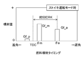
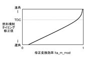
- FIG. 1 It is a figure which shows an example of the map which calculates the correction value of main injection timing. It is a figure explaining the concept of the torque compensation control implement
- FIG. 1 is a schematic diagram showing a configuration of an internal combustion engine (hereinafter referred to as “engine”) 1 according to the present embodiment and an exhaust purification system 2 including the control device.
- the engine 1 is based on so-called lean combustion in which the equivalence ratio of the air-fuel mixture is leaner than stoichiometric, more specifically, a diesel engine, a lean burn gasoline engine, or the like.
- the engine 1 will be described as a diesel engine.
- the exhaust purification system 2 includes a catalyst purification device 4 provided in the exhaust passage 11 of the engine 1, an EGR device 5 that recirculates part of the exhaust gas flowing through the exhaust passage 11 into the intake passage 12, the engine 1, and catalyst purification. And an electronic control unit (hereinafter referred to as “ECU”) 3 as a control device for controlling the device 4 and the EGR device 5.
- ECU electronice control unit
- the engine 1 is provided with a fuel injection valve that injects fuel into each cylinder (not shown).
- the actuator that drives the fuel injection valve is electromagnetically connected to the ECU 3.
- the ECU 3 determines the fuel injection amount from the fuel injection valve, the injection timing, and the like according to a procedure described in detail later, and controls the fuel injection valve so that the determined fuel injection mode is realized.
- the catalyst purification device 4 includes a first catalytic converter 41 provided upstream in the exhaust passage 11, a second catalytic converter 42 provided downstream from the first catalytic converter 41, and a second catalytic converter 42. And a reducing agent supply device 43 for supplying the reducing agent to the device.
- the first catalytic converter 41 is provided directly below the engine 1 in the exhaust passage 11. Therefore, hereinafter, the first catalytic converter is referred to as a direct catalytic converter.
- the second catalytic converter 42 is provided at a position away from the engine 1, more specifically, under the floor with the exhaust purification system 2 mounted on a vehicle (not shown). Therefore, hereinafter, the second catalytic converter is referred to as an underfloor catalytic converter.
- the direct catalytic converter 41 and the underfloor catalytic converter 42 are each provided with a catalyst for promoting a reaction for purifying components such as HC, CO, and NOx contained in the exhaust gas.
- the direct catalyst provided in the direct catalytic converter 41 a catalyst having at least a three-way purification function is used.
- the three-way purification function refers to a function in which a three-way purification reaction, that is, a reaction in which oxidation of HC and CO and reduction of NOx are performed simultaneously proceeds under an exhaust gas having a stoichiometric equivalent ratio.
- Examples of the catalyst having such a three-way purification function include an oxidation catalyst, a three-way catalyst, and a NOx occlusion reduction type catalyst. Any of these three catalysts is preferably used as the direct catalyst.
- the oxidation catalyst (DOC) purifies HC, CO, and NOx by the above three-way purification reaction under exhaust gas with a stoichiometric equivalent ratio, and purifies by oxidizing HC and CO under exhaust gas with a lean equivalent ratio.
- the three-way catalyst (TWC) corresponds to the oxidation catalyst added with an oxygen storage material.
- the three-way catalyst and the oxidation catalyst have the same basic purification function. However, the three-way catalyst is superior to the oxidation catalyst in that the three-way purification window is wide.
- NOx occlusion reduction catalyst (NSC) purifies HC, CO, NOx by a three-way purification reaction under exhaust gas with stoichiometric ratio, and stores NOx under exhaust gas with lean equivalent ratio. Purify by.
- the stored NOx is released by setting the equivalent ratio of exhaust gas to stoichiometric or richer than stoichiometric, and is reduced using HC contained in the exhaust gas as a reducing agent
- the underfloor catalyst provided in the underfloor catalytic converter 42 a catalyst that undergoes a NOx purification reaction under an exhaust gas having a lean equivalent ratio that contains a large amount of oxygen is used.
- the catalyst having such a NOx purification function include a selective reduction catalyst in addition to the NOx occlusion reduction type catalyst described above.
- the selective reduction catalyst (SCR) is supplied from the outside such as NH 3 or HC or reduces NOx in the presence of HC present in the exhaust gas.
- SCR selective reduction catalyst
- the underfloor catalyst is a selective reduction catalyst. Changes in the case where the underfloor catalyst is a NOx occlusion reduction type catalyst will be described later.
- the reducing agent supply device 43 includes a urea water tank 431 and a urea water injector 432.
- the urea water tank 431 stores urea water that is a precursor of the reducing agent (NH 3 ) in the underfloor catalytic converter 42.
- the urea water tank 431 is connected to the urea water injector 432 via a urea water supply path 433 and a urea water pump (not shown).
- the urea water injector 432 opens and closes when driven by an actuator (not shown), and injects urea water supplied from the urea water tank 431 to the upstream side of the underfloor catalytic converter 42 in the exhaust passage 11.
- the urea water injected from the injector 432 is hydrolyzed into NH 3 in the exhaust gas or in the underfloor catalytic converter 42 and consumed for NOx reduction.
- the actuator of the urea water injector 432 is electromagnetically connected to the ECU 3.
- the ECU 3 calculates the necessary urea water injection amount according to the output of the NOx sensor 22 described later, and controls the urea water injector 432 so that an amount of urea water corresponding to this injection amount is injected. A detailed description of urea water injection control by the ECU 3 is omitted.
- the EGR device 5 includes an EGR passage 51, an EGR control valve 52, an EGR cooler (not shown), and the like.
- the EGR passage 51 connects the intake passage 12 and the exhaust passage 11 upstream of the direct catalytic converter 41.
- the EGR control valve 52 is provided in the EGR passage 51 and controls the amount of exhaust gas (hereinafter referred to as “EGR gas”) recirculated into the cylinder of the engine 1 through the EGR passage 51.
- the actuator that drives the EGR control valve 52 is electromagnetically connected to the ECU 3.
- the ECU 3 calculates an estimated value of the EGR gas amount (or EGR rate), determines a target value of the EGR gas amount (or EGR rate) by a procedure described in detail later, and sets the estimated value to the target value. Controls the EGR control valve.
- the ECU 3 includes a LAF sensor 21, a NOx sensor 22, a catalyst temperature sensor 23, a crank angle position sensor 14, an accelerator opening sensor 15, an air flow sensor 16, and the like as sensors for detecting the states of the exhaust purification system 2 and the engine 1. Is connected.
- the LAF sensor 21 detects an equivalence ratio of exhaust gas downstream from the exhaust port of the engine 1 and upstream from the direct catalytic converter 41, and transmits a signal substantially proportional to the detected value to the ECU 3.
- the NOx sensor 22 detects the NOx concentration in the exhaust gas downstream of the underfloor catalytic converter 42 and transmits a signal substantially proportional to the detected value to the ECU 3.
- the catalyst temperature sensor 23 detects the temperature of the underfloor catalytic converter 42 and transmits a signal substantially proportional to the detected value to the ECU 3.
- the crank angle position sensor 14 detects the rotation angle of the crankshaft of the engine 1 and supplies a pulse signal for each predetermined crank angle to the ECU 3.
- the ECU 3 calculates the rotational speed NE of the engine 1 based on this pulse signal.
- the accelerator opening sensor 15 detects the amount of depression of an accelerator pedal (not shown) and transmits a signal substantially proportional to the detected value to the ECU 3.
- the ECU 3 calculates a driver request driving force Tdrv based on the crank angle position sensor 14 and the accelerator opening sensor 15.
- the air flow sensor 16 detects the flow rate of fresh air flowing through the intake passage 12, that is, the amount of fresh air supplied into the cylinder of the engine 1, and transmits a signal substantially proportional to the detected value to the ECU 3.
- a sensor abnormality warning lamp 17 is connected to the ECU 3 in order to notify the driver of the abnormality of the LAF sensor 21.
- the sensor abnormality warning lamp 17 is provided, for example, on the meter panel of the vehicle, and lights up when it is determined that the LAF sensor 21 is abnormal (see S41 in FIG. 18 described later).
- the ECU 3 shapes input signal waveforms from various sensors, corrects the voltage level to a predetermined level, converts an analog signal value into a digital signal value, and a central processing unit (hereinafter “ CPU ”).
- the ECU 3 stores a storage circuit that stores various calculation programs and calculation results executed by the CPU to execute equivalence ratio control, which will be described later, a fuel injection valve of the engine 1, a urea water injector 432, and EGR control. And an output circuit for outputting a control signal to the valve 52 and the like.
- FIG. 2 is a graph showing the temperature characteristics of the NOx purification performance of the underfloor catalyst responsible for NOx purification under exhaust gas having a lean equivalent ratio.
- the horizontal axis represents the catalyst temperature [° C.], and the vertical axis represents the NOx purification rate [%] under the exhaust gas having a lean equivalent ratio.
- a solid line indicates a case where the underfloor catalyst is a selective reduction catalyst (SCR catalyst), and a broken line indicates a case where the underfloor catalyst is a NOx occlusion reduction type catalyst (NSC).
- SCR catalyst selective reduction catalyst
- NSC NOx occlusion reduction type catalyst
- these underfloor catalysts exhibit high NOx purification performance when the equivalent ratio of exhaust gas is lean and the catalyst temperature is in an appropriate temperature range.
- the horizontal axis is the exhaust gas volume (the amount of exhaust gas per unit time)
- the upward convex characteristic is shown as in FIG.
- the equivalence ratio control of the present invention reduces the NOx purification performance of the underfloor catalyst by changing the equivalence ratio of the air-fuel mixture from lean to stoichiometric at the time of such a high load operation, thereby allowing the three-way purification reaction to proceed in the direct catalyst. Make up. Next, the concept of this equivalence ratio control will be described with reference to FIGS.
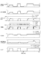
- FIG. 3 is a first diagram for explaining the concept of the equivalence ratio control of the present invention.
- FIG. 3 shows, in order from the top, the breakdown of the gas introduced into the cylinder, the Inert-EGR rate [%], the fuel injection amount, the LAF sensor output, and the NOx purification rate [%].
- Inert-EGR refers to an inert component excluding oxygen in the EGR gas recirculated into the cylinder through the EGR passage.
- the gas introduced into the cylinder is divided into a fresh air component including oxygen in the EGR gas and an Inert-EGR component.
- the two broken lines indicate the target value of the cylinder gas amount (target cylinder gas amount) and the target value of the Inert-EGR amount (target Inert-EGR amount).
- a value obtained by subtracting the target Inert-EGR amount from the target cylinder gas amount corresponds to the target value of the new air amount (target new air amount).
- two solid lines indicate the actual value of the cylinder internal gas amount (actual cylinder gas amount) and the actual value of the Inert-EGR amount (actual Inert-EGR amount), respectively.
- the value obtained by subtracting the actual Inert-EGR amount from the actual cylinder gas amount corresponds to the actual value of the new air amount (actual new air amount). Further, the actual cylinder gas amount and the actual Inert-EGR amount are controlled so as to follow respective target values.
- the target cylinder gas amount is determined so as to increase according to the driver's required driving force.
- the temperature of the exhaust gas increases and the exhaust gas volume also increases, so that the NOx purification performance of the underfloor catalyst decreases as described with reference to FIG. Therefore, in the equivalence ratio control of the present invention, the engine operation mode is switched between the lean operation mode and the stoichiometric operation mode by setting a predetermined threshold Gcyl_st with respect to the target cylinder gas amount.
- the ECU determines the fuel injection amount, the Inert-EGR rate, and the like with a predetermined algorithm so that the equivalence ratio of the air-fuel mixture becomes leaner than the stoichiometric ratio, and performs the NOx purification function by the underfloor catalyst. Use it actively to maintain a high NOx purification rate.
- the ECU controls the fuel injection amount, the Inert-EGR rate, etc. so that the equivalence ratio of the air-fuel mixture becomes stoichiometric, actively uses the three-way purification function by the direct catalyst, Compensates for the decline in NOx purification performance.
- the ECU increases the Inert-EGR rate (or the Inert-EGR amount) as compared with the case where the same ratio is determined by the same algorithm as in the lean operation mode in order to control the equivalence ratio of the air-fuel mixture stoichiometrically.
- Increase the fuel injection amount is preferably increased by intentionally reducing the combustion efficiency of the engine.
- combustion efficiency of the engine can be lowered by retarding the fuel injection timing as compared to the lean operation mode or dividing the fuel injection, as will be described in detail later.
- the combustion efficiency of the engine can be reduced by retarding the ignition timing.
- FIG. 4 is a second diagram for explaining the concept of the equivalence ratio control of the present invention.
- the exhaust gas equivalent ratio is stoichiometrically controlled by combining the increase in the Inert-EGR rate and the increase in the fuel injection amount.
- the Inert-EGR rate can be increased, for example, by adjusting the opening degree of the EGR control valve.
- the flow rate characteristic of the EGR control valve changes due to individual variations and aging. For this reason, as shown in FIG.
- FIG. 4 exemplifies a case where individual variation or aging has occurred in the EGR control valve. In addition to this, when individual variation or aging has occurred in the flow rate characteristics of the injector for injecting fuel, the LAF sensor output is similarly applied. In some cases, a steady deviation may occur.
- FIG. 5 is a third diagram for explaining the concept of the equivalence ratio control of the present invention.
- FIG. 5 shows the stoichiometric feedback control using the LAF sensor output from the time when the lean operation mode is switched to the stoichiometric operation mode (F_StoicMode: 0 ⁇ 1) and when a predetermined time has passed (F_StoicFB: 0 ⁇ 1). This is a case where the fuel injection amount is corrected so that the output of the LAF sensor becomes stoichiometric.
- F_StoicMode 0 ⁇ 1
- F_StoicFB 0 ⁇ 1
- the equivalence ratio of the air-fuel mixture is accurately controlled even when there are individual variations in the EGR control valve and the injector, and NOx purification is performed.
- the rate can be increased.
- the output of the LAF sensor is sufficiently smaller than the stoichiometric operation. Further, in order to control the equivalence ratio of the air-fuel mixture from this state to stoichiometric, it is necessary to increase the fuel injection amount. For this reason, if the above-described stoichiometric feedback control is started immediately after switching from the lean operation mode to the stoichiometric operation mode, the fuel injection amount may increase rapidly, and an unintended change in engine torque may occur.
- the stoichiometric feedback control starts in response to the output of the LAF sensor exceeding the feedback start equivalent ratio set to a value slightly smaller than the stoichiometric value after the start of the stoichiometric operation mode.
- the fuel injection amount is prevented from increasing rapidly, and an unintended torque change is suppressed.
- the engine operation mode is set to the stoichiometric operation mode immediately after the engine is started until the underfloor catalyst reaches the activation temperature, and the three-way purification function of the direct catalyst is utilized. Since the direct catalyst is provided at a position closer to the engine than the underfloor catalyst, the direct catalyst reaches its activity more quickly than the underfloor catalyst. Therefore, the NOx purification rate can be increased immediately after the start by setting the operation mode of the engine immediately after the start to the stoichiometric operation mode.
- FIG. 6 is a diagram showing a part of the main flowchart showing the procedure of the equivalence ratio control.
- This equivalence ratio control is executed in the ECU every predetermined control cycle (for example, TDC cycle).
- the equivalence ratio control executed in the ECU includes mode determination control (S1), EGR control (S2), fuel injection control (S3), and injection pattern control (S5). Including.
- the current appropriate operation mode is determined according to the state of the engine and the exhaust purification system. A specific procedure of the mode determination control will be described later with reference to FIG.
- the target EGR amount and the target EGR rate are determined according to the selected operation mode and the like. A specific procedure of this EGR control will be described later with reference to FIG.
- the fuel injection amount is determined according to the selected operation mode, the target EGR amount, and the like. A specific procedure of this fuel injection control will be described later with reference to FIGS.
- the fuel injection amount determined in S3 is divided according to the operation mode determined in S1. A specific procedure of this injection pattern control will be described later with reference to FIGS.
- FIG. 7 is a flowchart showing the procedure of the mode determination control.
- the ECU sets the values of the stoichiometric purification mode flag F_StoicMode and the stoichiometric feedback flag F_StoicFB.
- the stoichiometric purification mode flag F_StoicMode is a flag indicating that the current operation mode is the stoichiometric operation mode.
- the stoichiometric feedback flag F_StoicFB is a flag indicating that the state is suitable for execution of stoichiometric feedback control.
- the ECU determines whether or not the direct catalyst has reached activity. If the determination in S11 is YES, the process moves to S12. In S12, the ECU determines whether or not the underfloor catalyst has reached activity, that is, whether or not the underfloor catalyst temperature Tdenox (k) is equal to or higher than a threshold value Tdenox_act set to determine the activity. The underfloor catalyst temperature Tdenox (k) is calculated based on the output of the catalyst temperature sensor. If this determination is YES, the process proceeds to S13, and if NO, the process proceeds to S14.
- the ECU determines whether or not the target cylinder gas amount Gcyl_trgt (k) is equal to or greater than a predetermined stoichiometric operation threshold Gcyl_st_dnx after activation of the predetermined underfloor catalyst.
- the ECU determines whether or not the target in-cylinder gas amount Gcyl_trgt (k) is greater than or equal to a predetermined stoichiometric operation threshold Gcyl_st_aes before the underfloor catalyst activation.
- the target in-cylinder gas amount Gcyl_trgt (k) is determined for each predetermined control cycle by searching a predetermined map according to the driver's required driving force by a process (not shown). Further, the stoichiometric operation threshold Gcyl_st_dnx after under-floor catalyst activation is set to be greater than or equal to the stoichiometric operation threshold Gcyl_st_aes before under-floor catalyst activation (Gcyl_st_dnx ⁇ Gcyl_st_aes). In S13 and S14, the gas amount in the cylinder is determined as an argument, but substantially the same determination can be performed using physical quantities such as engine torque, engine output, and exhaust gas volume as arguments.
- the ECU sets a stoichiometric feedback flag F_StoicFB according to the following equation (2), and ends the process of FIG. More specifically, the ECU sets the flag F_StoicFB when the LAF sensor output ⁇ laf exceeds the feedback start threshold ⁇ fb set to a value slightly smaller than 1 (stoichiometric ratio) from the previous control to the current control. Is switched from 0 to 1, and the flag F_StoicFB is reset from 1 to 0 when the stoichiometric purification flag F_StoicMode is switched from 1 to 0 from the previous control to the current control. In other cases, the flag F_StoicFB is maintained in the previous state.
- the stoichiometric feedback control by the adaptive stoichiometric controller is performed after the engine operation mode is switched from the lean operation mode to the stoichiometric operation mode. It can be started after waiting for ⁇ laf to exceed the feedback start threshold ⁇ fb.
- FIG. 8 is a flowchart showing a procedure of EGR control.
- the ECU determines a target value (target EGR amount) Gegr_trgt of the EGR gas amount and a target value (target EGR rate) Regr_trgt of the EGR rate.
- S21 it is determined whether or not the current operation mode is the stoichiometric operation mode, that is, whether or not the stoichiometric purification flag F_StoicMode is 1. If the determination in S21 is NO, that is, if the lean operation mode is in progress, the process proceeds to S22, where the ECU maintains the state where the equivalence ratio of the air-fuel mixture is lean, and the required driving force of the driver
- the target EGR amount Gegr_trgt and the target EGR rate Regr_trgt are determined so as to be realized. These target EGR amount Gegr_trgt and target EGR rate Regr_trgt are determined by searching a map for a predetermined lean operation mode.
- the process proceeds to S23, and the ECU determines that the required driving force of the driver is realized, as will be described later with reference to FIG.
- the target EGR amount Gegr_trgt and the target EGR rate Regr_trgt are determined so that the equivalent ratio of the air-fuel mixture becomes stoichiometric with respect to the fuel injection amount Gfuel. More specifically, the ECU determines the target EGR amount Gegr_trgt and the target EGR rate Regr_trgt according to the following equations (3-1) to (3-4).
- Gfsh_trgt (k) is the target cylinder fresh air amount.
- Gfuel (k) is a fuel injection amount determined in fuel injection control described later.
- the constant ⁇ st is a stoichiometric air-fuel ratio (for example, 14.6). That is, the target in-cylinder fresh air amount Gfsh_trgt is set to an amount necessary for stoichiometric combustion of an amount of fuel that achieves the driver required driving force.
- Giegr_trgt (k) is the target Inert-EGR amount.
- Gcyl_trgt (k) is the target cylinder gas amount. That is, a value obtained by subtracting the target cylinder fresh air amount Gfsh_trgt (k) from the target cylinder gas amount Gcyl_trgt (k) becomes the target Inert-EGR amount Giegr_trgt (k).
- the target EGR amount Gegr_trgt (k) is determined according to the above equation (3-3) so that the target Inert-EGR amount Giegr_trgt (k) defined as described above is realized. More specifically, the target EGR amount Gegr_trgt (k) takes into account the time d (EGR recirculation time) required until the EGR gas is recirculated into the cylinder via the EGR passage, and the LAF before the EGR recirculation time d. A value obtained by multiplying the sensor output ⁇ laf (kd) by the current target Inert-EGR amount Giegr_trgt (k) is determined.
- the target EGR rate Regr_trgt (k) is calculated by dividing the target EGR amount Gegr_trgt (k) by the target in-cylinder gas amount Gcyl_trgt (k) as shown in the above equation (3-4).
- FIG. 9 is a block diagram relating to execution of fuel injection control for determining the fuel injection amount Gfuel of the engine.
- This fuel injection control is realized by combining functional blocks such as the fuel injection amount calculation unit 31, the lean operation mode controller 32, the adaptive feedback controller 34, and the LAF delay compensation identifier 35.
- the fuel injection amount calculation unit 31 uses either the fuel injection amount Gfuel_ln calculated by the lean operation mode controller 32 or the fuel injection amount (Gfuel_st or Gfuel_st_ff) calculated by the adaptive feedback controller 33 for the current engine. Select according to the operation mode. More specifically, the fuel injection amount calculation unit 31 has three fuels as shown in the following formula (4) according to the values of the flags F_StoicMode and F_StoicFB updated according to the above formulas (1) and (2). Any one of the injection amounts Gfuel_ln, Gfuel_st_ff, and Gfuel_st is determined as the final fuel injection amount Gfuel.
- the injection amount Gfuel_ln (k) is the fuel injection amount for the lean operation mode.
- the injection amount Gfuel_st_ff (k) is the injection amount during the stoichiometric operation mode and before starting the stoichiometric feedback control.
- the injection amount Gfuel_st (k) is an injection amount for stoichiometric feedback control.
- the lean operation mode controller 32 calculates an injection amount based on the driver required driving force Tdrv and the engine speed NE so that the driver required driving force is realized and the equivalence ratio of the air-fuel mixture becomes lean, This is determined as the fuel injection amount Gfuel_ln for the lean operation mode. More specifically, the lean operation mode controller 32 searches the predetermined lean operation mode map (not shown) by using the requested driving force Tdrv and the rotational speed NE as arguments, and thereby the injection amount Gfuel_ln. To decide.
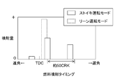
- the map used for calculating the injection amount Gfuel_ln is determined on the assumption that the fuel injection amount is divided in the manner shown by the broken line in FIG. 10 in the lean operation mode. Things are used. That is, in the lean operation mode, as shown by a broken line in FIG. 10, it is assumed that main injection executed near top dead center and pilot injection preceding this main injection are executed.
- the adaptive feedback controller 34 models the physical system from the fuel injection amount Gfuel to the output ⁇ laf of the LAF sensor using a predetermined model formula, and determines the injection amount Gfuel_st in the stoichiometric operation mode using this model.
- this model will be described in detail, and then a procedure for specifically determining the injection amount Gfuel_st using this model will be described.
- the gas introduced into the engine cylinder is composed of fresh air and EGR gas. Therefore, the equivalent ratio ⁇ exp of the exhaust gas at the exhaust port of the engine is expressed by the following formula (5-1) by the immediately preceding EGR rate Regr, the fresh air equivalent ratio ⁇ fsh, and the EGR gas equivalent ratio ⁇ egr.
- the equivalent ratio ⁇ fsh of fresh air in the equation (5-1) is calculated by dividing the fuel injection amount Gfuel by the fresh air amount Gfsh and multiplying by the stoichiometric air-fuel ratio ⁇ st (for example, 14.6) (the following equation (5) -2)).
- the EGR rate Regr and the fresh air quantity Gfsh are not quantities that can be directly observed.
- the target value Regr_trgt (see the above formula (3-4)) can be substituted for the EGR rate Regr.
- the new air amount Gfsh can be substituted with the output Gafs of the air flow sensor. That is, the following equation (7) is derived using the target value Regr_trgt of the EGR rate and the output Gafs of the air flow sensor.
- the exhaust port equivalent ratio ⁇ exp is divided into a term proportional to the fuel injection amount Gfuel and a disturbance term not proportional to the fuel injection amount Gfuel.
- the disturbance term is proportional to the EGR rate. Since a general diesel engine has a higher EGR rate than a gasoline engine, the contribution of this disturbance term is relatively large. Therefore, in the present invention, a model that accurately incorporates the disturbance term is constructed.
- the values of the model parameters A and B are expressed by the following equations (9-1) to (9-4) in consideration of an error (modeling error) between the theoretical equation (7) and the actual system.
- the reference values Abs and Bbs calculated from the parameter Regr_trgt relating to the EGR rate and the correction values dA and dB as modeling errors are defined separately.
- the physical quantities Regr and Gfsh are substituted in deriving the theoretical formula (7).
- Modeling errors, modeling errors due to individual variations such as flow characteristics of EGR control valves and fuel injection valves, observation accuracy of air flow meters and LAF sensors, and changes over time are expressed by these two correction values dA and dB.
- the LAF sensor has a response delay characteristic.
- This response delay characteristic changes due to individual variation and aging.
- soot is contained in the exhaust gas, so that the response delay characteristic of the sensor changes due to the soot adhering to the detection element of the LAF sensor.
- the LAF sensor output ⁇ laf has such a response delay characteristic, and if this characteristic is expressed by a first-order delay coefficient C, the LAF sensor output ⁇ laf and the exhaust gas equivalent ratio ⁇ exp at the exhaust port
- the second model formula shown in the following formula (10) is derived.
- the coefficient C in the second model formula is referred to as a response delay coefficient of the LAF sensor.
- the system from the fuel injection amount Gfuel to the output ⁇ laf of the LAF sensor has the first model formula (the above formulas (8) and (9-1) to (9-4)) and the second model formula. (Equation (10) above)
- a model constituted by the first and second model formulas is referred to as an injection amount-sensor output model.
- the system from the exhaust gas equivalent ratio ⁇ exp at the exhaust port to the output ⁇ laf of the LAF sensor is configured only by the second model equation.
- a model constituted by the second model formula is referred to as a port equivalence ratio-sensor output model.
- the adaptive feedback controller 34 includes a feedback identifier 36 and a stoichiometric operation mode controller 37.
- the feedback identifier 36 uses the above-described injection amount-sensor output model to sequentially identify the values of the model parameters A and B included in this model at a predetermined timing.
- the stoichiometric operation mode controller 37 calculates the injection amount Gfuel_st for stoichiometric feedback control using the model parameters A and B whose values are identified by the feedback identifier 36.
- the LAF delay compensation identifier 35 sequentially identifies the value of the response delay coefficient C included in this model using the above-described port equivalent ratio-sensor output model. As shown in FIG. 9, the LAF delay compensation identifier 35 is configured separately from the feedback identifier 36, and the value of the response delay coefficient C is calculated by a calculation independent of the feedback identifier 36. It is possible to identify.
- the feedback identifier 36 uses an injection amount-sensor output model to calculate the estimated value ⁇ exp_hat of the exhaust gas equivalent ratio at the exhaust port and the estimated value ⁇ laf_hat of the LAF sensor output by the following equations (11-1) and (11-2). ).
- the feedback identifier 36 identifies an error between the output value ⁇ laf (k) of the LAF sensor and the estimated value ⁇ laf_hat (k) of the LAF sensor output derived from the model equations (11-1) and (11-2).
- E_id (k) is defined by the following equation (12), and the two model parameter values A (k) and B (k) are sequentially identified so that the identification error E_id (k) is minimized.
- a model parameter vector ⁇ having the model parameters A and B as components is defined by the following equation (13).
- this model parameter vector ⁇ is defined as the sum of a reference vector ⁇ bs that can be successively calculated according to a parameter such as an EGR rate and a correction vector d ⁇ corresponding to a modeling error (the following equations (14-1) and ( 14-2)).
- a parameter such as an EGR rate
- d ⁇ a correction vector d ⁇ corresponding to a modeling error
- the correction vector d ⁇ that minimizes the identification error E_id (see the above equation (12)) is calculated by the following equation (15) according to the sequential least squares algorithm.
- the matrix ⁇ is an example of forgetting and is defined by the following equation (16-4).
- the diagonal components ⁇ 1, ⁇ 2 of the forgetting matrix ⁇ are set between 0 and 1, respectively.
- either ⁇ 1 or ⁇ 2 is preferably 1.
- the matrix Kp is a model parameter update gain matrix and is defined by the following equation (16-1).
- the matrix P is an adaptive gain matrix and is defined by the following equation (16-3).
- the diagonal components p1 and p2 of the adaptive gain matrix P are set to positive values, respectively.
- the vector ⁇ is an input / output vector and is defined by the following equation (16-2).
- the stoichiometric operation mode controller 37 determines the feedforward injection amount Gfuel_st_ff for starting the stoichiometric operation mode and the injection amount Gfuel_st for stoichiometric feedback control by different algorithms, as will be described in the following order.
- the feedforward injection amount Gfuel_st_ff for starting the stoichiometric operation mode is a map (not shown) for a predetermined stoichiometric operation mode in the stoichiometric operation mode controller 37 with the driver requested driving force Tdrv and the engine speed NE as arguments. ).
- the map for the stoichiometric operation mode is different from the map referred to in the lean operation mode controller 32 described above, and the output of the LAF sensor is stoichiometric with respect to arguments such as the required driving force Tdrv and the rotational speed NE. What is set to be used is used.
- the map for the stoichiometric operation mode is a map determined on the premise that the fuel injection amount is divided in the manner shown by the solid line in FIG. 10 in the stoichiometric operation mode. That is, in the stoichiometric operation mode, as shown by a solid line in FIG. 10, it is assumed that after injection executed during the expansion stroke is executed in addition to main injection and pilot injection.
- the injection amount Gfuel_st for stoichiometric feedback control is calculated in the stoichiometric operation mode controller 37 based on the two model parameters A and B of the injection amount-sensor output model. More specifically, the stoichiometric operation mode controller 37 first corresponds to the target value (target equivalent ratio) ⁇ trgt with respect to the exhaust gas equivalent ratio ⁇ exp at the exhaust port so that the three-way purification reaction proceeds in the direct catalyst. 1 (see equation (17) below), or a preset value near the stoichiometric value or a value near the stoichiometric value calculated by a predetermined algorithm.
- the stoichiometric operation mode controller 37 causes the equivalent ratio ⁇ exp calculated using the model parameters A and B (see the above equation (8)) to be the target equivalent ratio ⁇ trgt determined by the above equation (17).
- the injection amount Gfuel_st is determined (see the following equation (18-1)).
- the target equivalent ratio ⁇ trgt of the above formula (17) is equal to the equivalent ratio ⁇ exp derived from the model formula (8). Is derived by
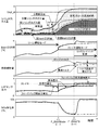
- FIG. 11 is a diagram for explaining the concept of equivalence ratio control realized by the adaptive stoichiometric controller 34.
- the breakdown of the gas introduced into the cylinder the Inert-EGR rate [%]
- the model parameter vectors ⁇ and ⁇ bs identified by the feedback identifier 36 the model parameter vectors ⁇ and ⁇ bs identified by the feedback identifier 36, the fuel injection amount, the LAF sensor output, And NOx purification rate [%].
- the engine operation mode is switched from the lean operation mode to the stoichiometric operation mode in response to the target cylinder gas amount Gcyl_trgt exceeding the threshold value Gcyl_st_dnx or Gcyl_st_aes (see the above equation (1)). ).
- the feedback identifier 36 minimizes the error between the output value of the LAF sensor and the estimated value based on the fuel injection amount-sensor output model.
- the value of the model parameter vector ⁇ is updated (see the above equation (15)). Thereby, as shown in FIG. 11, the value of the model parameter ⁇ changes from the reference value ⁇ bs. That is, the error between the actual system and the model is detected by the feedback identifier 36 from the time of switching to the stoichiometric operation mode.
- the fuel injection amount Gfuel is changed from the injection amount Gfuel_ln for the lean operation mode to the feedforward injection amount Gfuel_st_ff for the stoichiometric operation mode (the above formula (4)) reference).
- the output of the LAF sensor increases toward the stoichiometric.
- the stoichiometric purification flag F_StoicFB is switched from 0 to 1, and the stoichiometric feedback control is started (see the above formula (2)).
- the fuel injection amount Gfuel is changed from the feedforward injection amount Gfuel_st_ff to the injection amount Gfuel_st for stoichiometric feedback control (see the above formula (4)).
- the injection amount Gfuel_st is determined so that the exhaust port equivalence ratio ⁇ exp obtained from the model equation (8) becomes a target value (stoichiometric) (see the above equations (17) and (18-1)).
- the output of the LAF sensor is stoichiometrically controlled after the start of the stoichiometric feedback control, and the three-way purification reaction by the direct catalyst proceeds.
- a modeling error is detected by the feedback identifier early from the time when the operation mode is switched from the lean operation mode to the stoichiometric operation mode. By doing so, it becomes possible to control the output of the LAF sensor quickly and accurately in a stoichiometric manner. Thereby, the time (stoichi purification time) during which the three-way purification reaction can proceed in the direct catalyst can be ensured as long as possible.
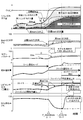
- FIG. 12 is a diagram showing a simulation result of the adaptive stoichiometric controller.
- FIG. 12 shows the fuel injection amount, LAF sensor output, equivalence ratio ( ⁇ fsh, ⁇ exp, ⁇ egr), EGR rate, model parameter A when the target cylinder gas amount is changed in the manner shown in the figure. , B, and flag changes.
- the stoichiometric purification mode flag F_StoicMode is set to 1 in accordance with this, and then the stoichiometric feedback flag F_StoicFB is set to 1.
- the output of the LAF sensor can be controlled stoichiometrically with high accuracy without exhibiting overshoot or vibrational behavior. Verified.
- this simulation of FIG. 12 was performed under the condition that a steady deviation occurs between the EGR rate Regr and its target value Regr_trgt, assuming that the EGR device has individual variations and aging.
- the adaptive stoichiometric controller detects individual variations of the EGR device as an error from the reference values Abs and Bbs of the model parameters A and B immediately after the start of the stoichiometric operation mode. For this reason, the adaptive stoichiometric controller can control the equivalence ratio of the air-fuel mixture with high accuracy regardless of individual variations such as the EGR device, the fuel injection valve, and the air flow meter.
- FIG. 13 is a diagram showing a simulation result of the conventional apparatus.
- the conventional apparatus differs from the adaptive stoichiometric controller in that the feedforward is performed by a known PI controller with the deviation E_phi between the LAF sensor output value ⁇ laf and its target value (stoichiometric) as an input. This is a value obtained by determining the correction injection amount ⁇ Gfuel_fb with respect to the injection amount Gfuel_st_ff.
- Other simulation conditions are the same as those in FIG.
- the LAF delay compensation identifier 35 identifies the value of the delay coefficient C (see the above equation (10)) included in the fuel injection amount-sensor output model used in the adaptive stoichiometric controller 33. First, the influence of the error of the delay coefficient C on the control result of the adaptive stoichiometric controller 33 will be described.
- FIG. 14 is a diagram showing the influence of the estimation error of the response delay characteristic of the LAF sensor on the control result.
- the adaptive stoichiometric controller uses the model parameter A so that the estimated value ⁇ laf_hat of the output of the LAF sensor matches the output value ⁇ laf of the LAF sensor under the delay coefficient C identified by the LAF delay compensation identifier. , B are identified, and the fuel injection amount is determined based on these model parameters A, B. Therefore, as a result of determining the fuel injection amount in this way, the value of the delay coefficient C needs to be accurately identified in order for the output LAf of the actual LAF sensor to match the estimated value ⁇ laf_hat as assumed in the model. There is.
- FIG. 14A shows the behavior when the delay of the actual LAF sensor is larger than the estimation
- FIG. 14B shows the behavior when the delay of the actual LAF sensor is almost the same as the estimation
- FIG. 14C shows the behavior when the delay of the actual LAF sensor is smaller than the estimation.
- the estimated value ⁇ laf_hat and the actual output value ⁇ laf of the LAF sensor exhibit the same behavior.
- FIGS. 14A and 14C if there is an error in the estimation of the delay coefficient C, the actual output value ⁇ laf may overshoot or delay with respect to the estimated value ⁇ laf_hat. For this reason, the stoichiometric purification time is shortened.
- the value of the delay coefficient C needs to be accurately identified sequentially.
- the delay characteristic of the LAF sensor greatly varies depending on the exhaust gas volume.
- the value of the delay coefficient C is successively changed greatly according to the operating state.
- the equivalent value ⁇ exp of the exhaust port that cannot be actually observed is estimated value ⁇ exp_hat that can be calculated by the equation (11-1).
- the value of the delay coefficient C is identified by using the model formula obtained by replacing (see formula (19) below).
- the delay characteristic of the LAF sensor has a characteristic that varies depending on the exhaust gas volume. More specifically, there is a characteristic that the delay characteristic of the LAF sensor decreases as the exhaust gas volume increases. It is difficult to directly calculate such a value that fluctuates successively in such a manner that the error between the virtual output W and the estimated value W_hat is minimized, and the error is large. Therefore, the LAF delay compensation identifier 35 defines a reference delay coefficient Cbs (k) as a function of the exhaust gas volume as shown in FIG. 15, and a delay coefficient C (k) as shown in the following equation (21). Is divided into the product of the reference delay coefficient Cbs (k) and the correction coefficient Kc (k) of the delay coefficient.
- the delay coefficient C (k) is separated into the product of the reference value Cbs (k) that changes due to the exhaust gas volume and the correction coefficient Kc (k) that changes due to other factors such as individual dispersion and soot adhesion. To do.
- the delay coefficient C (k) in this way, the portion of the delay coefficient C (k) that varies greatly depending on the exhaust gas volume is shown in FIG. 15 using the exhaust gas volume as an argument without going through the identification algorithm. It can be calculated by searching such a map.
- the correction coefficient Kc (k) of the delay coefficient is a linear function of a plurality of weight functions ⁇ i (k) using the exhaust gas volume as an argument, as shown in the following equation (22). Define as a join.
- the coefficient Kc_i associated with each weight function ⁇ i (k) is referred to as a local correction coefficient. In the following, a case where the number of weight functions is 3 will be described as an example.
- FIG. 16 is a diagram illustrating a setting example of the weight function ⁇ i.
- the domain of each weight function ⁇ i overlaps, and the sum of the values of the weight function ⁇ i is for all exhaust gas volumes. Are set equal to each other. Further, in the region where the reference delay coefficient Cbs changes greatly, the error is considered to change greatly. Therefore, as shown in FIG. 16, it is preferable to set the weighting function ⁇ i to be dense in a region where the reference delay coefficient Cbs changes greatly (region where the exhaust gas volume is small).
- the delay error C (k) is expressed by the linear combination of the local correction coefficient Kc_i as described above, and the identification error E_id ′ between the virtual output W and its estimated value W_hat is minimized.
- the value of each local correction coefficient Kc_i is identified.
- the value of the local correction coefficient Kc_i is expressed by the following equation (23).
- the coefficient Kp ′ is a corrected gain update gain, and is represented by the following equation (24-1).
- the coefficient P is an adaptive gain and is set to a predetermined positive value.
- the coefficient ⁇ ′ is a delay coefficient identification virtual input value, and is represented by the following equation (24-2).
- the estimated value ⁇ exp_hat of the equivalence ratio described above may include a steady-state error caused by individual variations such as a fuel injection valve, an EGR device, an air flow sensor, or a secular change. For this reason, if the delay coefficient C (k) is identified such that the estimated value W_hat of the virtual input calculated from the estimated value ⁇ exp_hat and the virtual input W always match, this error accumulates, and the delay coefficient C An error may occur in (k).
- the delay coefficient C (k) is a coefficient representing a transient characteristic of the output of the LAF sensor. Therefore, it is preferable to identify the value of the delay coefficient C (k) while the output of the LAF sensor is changing.
- the LAF delay compensation identifier updates the value of the delay coefficient C (k) only at the time of transition in which a significant change appears in the output value of the LAF sensor. More specifically, as shown in the following formula (25-1), the LAF delay compensation identifier updates the value of the transient determination flag F_Trans in accordance with the fluctuation of the output value of the LAF sensor, and the following formula (25 As shown in -2), an identification error that is not 0 is input only while it is determined to be in a transient state.
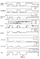
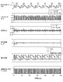
- FIG. 17 is a diagram showing a simulation result of the LAF delay compensation identifier.
- FIG. 17 shows changes in the output of the LAF sensor, the virtual input W, the identification error E_id ′, the delay coefficient C, and the transient determination flag F_Trans when the exhaust gas volume is changed in the manner shown in the figure.
- the output of the LAF sensor also changes periodically, and the transient determination flag F_Trans also changes periodically accordingly.
- the value of the delay coefficient C (k) is updated only while the transient determination flag F_Trans is 1.
- the delay coefficient C initially deviates from the actual delay coefficient and changes on the reference value Cbs side. It will show almost the same behavior.
- the value of the identification error E_id ′ at this time also converges to 0 with the passage of time. From the above, the superiority of the LAF delay compensation identifier of the present embodiment was verified.
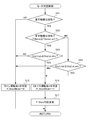
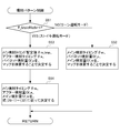
- FIG. 18 is a flowchart showing the procedure of the fuel injection control as described above.
- the ECU determines the fuel injection amount Gfuel according to the operation mode according to the following procedure.
- the ECU determines whether or not various sensors such as a LAF sensor and a temperature sensor related to execution of fuel injection control are normal. If the determination in S31 is NO, the ECU proceeds to S32, determines the lean operation injection amount Gfuel_ln as the fuel injection amount Gfuel regardless of the current operation mode, and ends this process. If the determination in S31 is YES, the ECU proceeds to S33.
- various sensors such as a LAF sensor and a temperature sensor related to execution of fuel injection control are normal. If the determination in S31 is NO, the ECU proceeds to S32, determines the lean operation injection amount Gfuel_ln as the fuel injection amount Gfuel regardless of the current operation mode, and ends this process. If the determination in S31 is YES, the ECU proceeds to S33.
- the ECU executes the calculations shown in the above equations (11-1) to (16-4), identifies the values of the model parameters A and B, and proceeds to S36.
- the ECU executes the calculations shown in the above equations (19) to (25-2), identifies the value of the delay coefficient C of the LAF sensor, and proceeds to S40.
- the ECU determines whether or not the value of the correction coefficient Kc of the delay coefficient C is smaller than a predetermined abnormality determination threshold value Kc_Aged. If the determination in S40 is NO, the ECU determines that the LAF sensor is normal and ends this process. If the determination in S40 is YES, the ECU determines that the LAF sensor is in an abnormal state with a large delay, moves to S41, turns on the warning lamp, and then ends this process.
- the LAF delay compensation identifier updates the value of the delay coefficient C regardless of the operation mode, whereas the feedback identifier is in the stoichiometric operation mode. Only update the values of model parameters A and B. That is, the LAF delay compensation identifier updates the value of the delay coefficient C under a wider operating condition than the feedback identifier.
- the LAF delay compensation identifier updates the value of the delay coefficient C under a wider operating condition than the feedback identifier.
- FIG. 19 is a diagram illustrating torque steps that can be generated by the fuel injection control described above. More specifically, FIG. 19 is a diagram schematically showing torque steps that may occur when fuel is injected in the same injection mode before and after starting the stoichiometric feedback control in the stoichiometric operation mode. It is. As described above, when the stoichiometric feedback control is started, the fuel injection amount Gfuel is changed from the feedforward injection amount Gfuel_st_ff to the injection amount Gfuel_st for stoichiometric feedback control.
- the injection amount Gfuel_st becomes larger than the feedforward injection amount Gfuel_st_ff so that the output of the LAF sensor is closer to the stoichiometry from the lean side than the stoichiometry. For this reason, if fuel is injected in the same manner before and after the start of the stoichiometric feedback control, an unintended torque step as illustrated may occur. Below, the procedure of the injection pattern control for eliminating such a torque level difference is demonstrated.
- FIG. 20 is a flowchart showing the procedure of injection pattern control.
- the ECU determines an injection pattern that does not change the fuel injection amount Gfuel that is determined so as to optimize the equivalent ratio of exhaust gas in the fuel injection control and that does not cause the torque step.
- the injection pattern includes a main injection timing ⁇ m corresponding to the timing of executing the main injection, an after injection timing ⁇ a corresponding to the timing of executing the after injection, a pilot injection amount Gf_p corresponding to the fuel amount injected by the pilot injection, and the main injection It is characterized by a plurality of fuel injection parameters such as a main injection amount Gf_m corresponding to the fuel amount to be injected and an after injection amount Gf_a corresponding to the fuel amount to be injected by the after injection. Note that a fixed value is used for the pilot injection timing ⁇ p corresponding to the timing at which pilot injection is performed, or a value that is uniquely determined according to the fuel injection parameter or the like. .
- the ECU determines whether or not the stoichiometric operation mode is in effect, that is, whether or not the stoichiometric purification flag F_StoicMode is 1. If the determination in S51 is NO and the ECU is in the lean operation mode, the ECU proceeds to S52, and if the determination in S51 is YES and the operation is in the stoichiometric operation mode, the ECU proceeds to S53.
- the ECU is assumed to execute only the pilot injection and the main injection, and the fuel injection parameters ( ⁇ m, Gf_m related to the execution of the pilot injection and the main injection) are assumed.
- Gf_p is determined (S52), and this process ends.
- the main injection timing ⁇ m, in the lean operation mode is determined by searching the main injection timing determination map shown in FIG. 22 using, for example, the estimated value of the Inert-EGR rate (or the estimated value of EGR rate Regr_hat) as an argument. Is done.
- the main injection timing ⁇ m is determined so as to be corrected toward the advance side in the vicinity of the top dead center as the Inert-EGR rate increases.
- the main injection amount Gf_m and the pilot injection amount Gf_p are determined by searching the map for the lean operation mode so as to divide the fuel injection amount Gfuel determined in the previous fuel injection amount control.
- the ECU In the stoichiometric operation mode, as shown in FIG. 23, the ECU is assumed to execute pilot injection, main injection, and after injection, and fuel related to execution of these pilot injection, main injection, and after injection.
- the values of the injection parameters ( ⁇ m, ⁇ a, Gf_m, Gf_p, Gf_a) are determined by the procedure described below (S53, S54), and this process ends.
- the ECU determines the provisional value ⁇ m_tmp of the main injection timing, the after injection timing ⁇ a, and the pilot injection amount Gf_p.
- the temporary value ⁇ m_tmp of the main injection timing is determined by searching the main injection timing determination map shown in FIG. 22 as in the lean operation mode.
- the after injection timing ⁇ a and the pilot injection amount Gf_a are determined by searching a map for the stoichiometric operation mode.
- the ECU determines the values of the main injection timing ⁇ m, the main injection amount Gf_m, and the after injection amount Gf_a according to the following procedure.
- two injection amounts are used to determine the main injection amount Gf_m and the after injection amount Gf_a so as to realize the driver's required driving force Tdrv and to divide the fuel injection amount Gfuel determined by the fuel injection control.
- the following two identities are imposed on Gf_m and Gf_a.
- coefficients Ita_m (k) and Ita_a (k) correspond to the torque conversion efficiencies of main injection and after injection, respectively, and search the map shown in FIG. 24 using each injection timing as an argument. It is calculated by.
- the ECU adjusts the provisional value ⁇ m_tmp of the main injection timing so that the after injection amount Gf_a does not exceed the upper limit value Gf_a_max, and determines the final main injection amount Gf_m and the after injection amount Gf_a.
- the ECU first searches the map using the after-injection timing ⁇ a determined in S54 and the provisional value ⁇ m_tmp of the main injection timing as arguments, and the torque conversion efficiency Ita_a_tmp, tentative after-injection and main injection Calculate Ita_m_tmp. Then, the ECU substitutes these torque conversion efficiencies Ita_a_tmp and Ita_m_tmp into the above formulas (27-1) and (27-2), so that the after injection amount shown in the following formulas (28-1) and (28-2) The temporary value Gf_a_tmp and the temporary value Gf_m_tmp of the main injection amount are calculated.
- the ECU compares the calculated provisional value Gf_a_tmp of the after injection amount with the upper limit value Gf_a_max, and if the provisional value Gf_a_tmp is smaller than the upper limit value Gf_a_max, the ECU sets the provisional value Gf_a_tmp as the fixed value Gf_a (k) of the after injection amount.
- the provisional value Gf_a_tmp is equal to or higher than the upper limit value Gf_a_max
- the upper limit value Gf_a_max is determined as the after-injection amount fixed value Gf_a (k) (see the following formula (29)).
- the ECU determines the provisional value Gf_m_tmp as the final value Gf_m (k) of the main injection amount, and the provisional value Gf_a_tmp is equal to or greater than the upper limit value Gf_a_max.
- the correction value Gf_m_mod is determined as the main injection amount fixed value Gf_m (k) (see the following equation (30-1)).
- the correction value Gf_m_mod (k) for the main injection amount as shown in the following equation (30-2), a value obtained by increasing the post injection amount by the upper limit value Gf_a_max is used.
- the ECU determines the provisional value ⁇ m_tmp as the final value ⁇ m (k) of the main injection timing, and the provisional value Gf_a_tmp is greater than or equal to the upper limit value Gf_a_max.
- the correction value ⁇ m_mod is determined as the final value ⁇ m (k) of the main injection timing (see the following formula (31)).
- the correction value ⁇ m_mod (k) of the main injection timing is calculated by the following procedure.
- the after injection amount Gf_a is limited by the upper limit value Gf_a_max
- the modified value Gf_m_mod that is increased by the corresponding amount is used as the main injection amount Gf_m.
- the necessary torque conversion efficiency Ita_m_mod of the main injection is calculated from the above equation (26-1) (see the following equation (32)).
- the correction value ⁇ m_mod of the main injection timing is determined by searching the map shown in FIG. 25 using the torque conversion efficiency Ita_m_mod as an argument. Note that the map of FIG. 25 corresponds to a map obtained by switching the input and output of the map shown in FIG.
- the provisional value Gf_a_tmp of the after injection amount exceeds the upper limit value Gf_a_max
- the after injection amount is limited by the upper limit value Gf_a_max
- the main injection amount is corrected from the provisional value Gf_m_tmp to the increase side accordingly.
- the main injection timing is corrected from the provisional value ⁇ m_tmp to the retard side so that the combustion efficiency is lowered.
- FIG. 26 is a diagram for explaining the concept of torque compensation control realized by executing the injection pattern control described above.
- the lean operation mode is switched to the stoichiometric operation mode, after injection is executed in addition to main injection. Thereafter, when the stoichiometric feedback control is started, the fuel injection amount is increased so that the output of the LAF sensor becomes stoichiometric from the lean side. At this time, the fuel injection amount determined so that the equivalence ratio becomes stoichiometric is appropriately divided into the after injection amount and the main injection amount according to the above equations (26-1) to (32). Thus, it is possible to suppress the occurrence of a torque step while controlling the equivalence ratio such that the three-way purification reaction proceeds with the direct catalyst.
- FIG. 27 is a block diagram showing the procedure of calculation (see the above equations (11-1) to (16-4)) in the feedback identifier 32 of the above embodiment.
- the feedback identifier 32 receives the fuel injection amount Gfuel (k-1) and the reference value Bbs (see the above equation (9-4)) as input, and includes an injection amount-sensor including model parameters A and B and a response delay coefficient C.
- the LAF sensor output estimation calculation unit 321 for calculating the estimated value ⁇ laf_hat (k) of the LAF sensor output by the equations (11-1) and (11-2) using the output model, the estimated value ⁇ laf_hat (k) and the LAF sensor
- the values A (k) and B (k) of the two model parameters are set to the above equation (13) so that the identification error E_id (k) (see equation (12)) with the output value ⁇ laf (k) of
- an identification calculation unit 322 that sequentially identifies according to the procedure described with reference to (16-4).
- the feedback identifier 32 uses the delay coefficient C (k) identified by the LAF delay compensation identifier 35 provided separately from the feedback identifier 32 and uses the delay coefficient C (k) as shown by the arrow in FIG.
- the model parameter values A (k) and B (k) are identified.
- the calculation in the LAF sensor output estimation calculation unit 321 is performed by the equation (11-1) including the model parameters A and B with the fuel injection amount Gfuel (k-1) as an input.
- the identification speed of the identification computing unit 322 is set so that the computation of the model parameter values A (k) and B (k) does not become unstable (the above formula (16 ⁇ 3) needs to be sufficiently slow. In other words, the identification speed of the model parameter values A (k) and B (k) of the feedback identifier 32 is limited.
- FIG. 28 is a block diagram showing a calculation procedure in a modification 32A of the feedback identifier configured to improve the identification speed.
- This feedback identifier 32A is obtained by equivalently converting the feedback identifier 32 of FIG.
- the feedback identifier 32A includes a delay calculation unit 323A that performs a delay calculation characterized by a delay coefficient C on the fuel injection amount Gfuel (k-1) and the reference value Bbs, and a model parameter A on the output of the delay calculation unit 323A.
- B by performing a predetermined calculation characterized by LAF sensor output estimation calculation unit 321A for calculating an estimated value ⁇ laf_hat (k) of the LAF sensor, an estimated value ⁇ laf_hat (k), and an output value ⁇ laf ( an identification calculation unit 322A that sequentially identifies the values A (k) and B (k) of the two model parameters so that the identification error E_id (k) (see Expression (12)) with respect to k) is minimized. Consists of.
- the delay calculation unit 323A performs the delay coefficient C (k) identified by the LAF delay compensation identifier 35 on the fuel injection amount Gfuel, the value Gfuel ⁇ Abs obtained by multiplying the fuel injection amount by the reference value, and the reference value Bbs. ) Is used to calculate the following filter values AG_f (k), Bbs (k), and Gf_f (k) (see the following equations (33-1) to (33-3)).
- the LAF sensor output estimation calculation unit 321A calculates the filter values AG_f (k), Bbs (k), and Gf_f (k) expressed by the following equation (34) characterized by the corrected values dA and dB of the model parameters A and B. To calculate the estimated value ⁇ laf_hat (k) of the output of the LAF sensor.
- the identification calculation unit 322A determines an identification error E_id between the output value ⁇ laf (k) of the LAF sensor and the estimated value ⁇ laf_hat (k) of the LAF sensor output derived from the model equations (11-1) and (11-2).
- the correction values dA (k) and dB (k) of the two model parameters are sequentially identified so that is minimized.
- the estimated value ⁇ laf_hat (k) includes a term that is not proportional to any of the correction values dA and dB of the model parameter, as shown in the equation (34), the equation (12) above shows. Thus, it is not possible to directly identify the correction values dA (k) and dB (k) so that the identification error E_id is defined.
- the identification calculation unit 322A does not directly handle the output of the LAF sensor, but uses the constant values AG_f (k) and Bbs (k) on the right side of the above equation (34) from the output value ⁇ laf (k) of the LAF sensor. ) Subtracted from the virtual output V (k) (see the following equation (35-1)), an estimated value V_hat (k) of the virtual output V (k) (see the following equation (35-2)), and And an identification error E_id ′′ (k) defined by these deviations is used (see the following equation (35-3)).
- a correction vector d ⁇ ′ having the correction values dA and dB of the model parameters A and B as components is defined by the following equation (36-1), and the input / output vector ⁇ ′ is defined by the following equation (36-2).
- the correction vector d ⁇ ′ that minimizes the identification error E_id ′′ (k) is calculated by the following equation (37) as in the above equation (15), according to the sequential least squares algorithm.
- the matrix ⁇ ′ is a forgetting example and is defined by the following equation (38-3).
- the diagonal components ⁇ 1 ′ and ⁇ 2 ′ of the forgetting matrix ⁇ ′ are set between 0 and 1, respectively.
- either ⁇ 1 ′ or ⁇ 2 ′ is preferably 1.
- the matrix Kp ′ is a model parameter update gain matrix, and is defined by the following equation (38-1).
- the matrix P ′ is an adaptive gain matrix and is defined by the following equation (38-2).
- the diagonal components p1 ′ and p2 ′ of the adaptive gain matrix P ′ are each set to a positive value.
- the identification calculation unit 322A identifies the corrected values dA and dB of the model parameters A and B that minimize the redefined identification error E_id ′′ by the calculation formula as described above. Note that the values of the model parameters A and B are calculated from the equations (9-1) and (9-2). According to the feedback identifier 32A shown in FIGS. 28 and 29 described above, unlike the feedback identifier 32 shown in FIG. 27, the filter element G is included in the calculation loop of the model parameters A (k) and B (k). Since (z) does not exist, the identification speed of the identification calculation unit 322A can be improved.
- the underfloor catalyst is a selective reduction catalyst, but the present invention is not limited to this.
- the underfloor catalyst is also effective as a NOx storage reduction catalyst.
- FIG. 30 is a diagram showing a configuration of the exhaust purification system 2A when the underfloor catalyst of the underfloor catalytic converter 42A is a NOx occlusion reduction type catalyst.
- the reducing agent supply device 43 is necessary to supply the reducing agent to the selective reduction catalyst.
- the NOx occlusion reduction type catalyst uses HC in the exhaust gas as a reducing agent, it is not necessary to provide a reducing agent supply device in this exhaust purification system 2A.
- the ECU 3A explains the equivalence ratio control in which the equivalent ratio of exhaust gas is made richer than stoichiometric or stoichiometric in order to reduce the NOx adsorbed by the NOx occlusion reduction type catalyst in the above embodiment. It is necessary to appropriately execute it separately from the equivalent ratio control.
- a LAF sensor (or oxygen concentration sensor) 22A is provided upstream of the underfloor catalytic converter 43A.
- the direct catalyst and the underfloor catalyst are used.
- the catalyst may be integral.
- an oxidation catalyst (or a three-way catalyst) 44B may be further provided upstream of the LAF sensor 21, as shown in FIG.
- the engine is a diesel engine.
- the present invention is not limited to this, and a lean combustion gasoline engine may be used.
- the injection amount-sensor output model (see equations (8) to (10)) with the fuel injection amount Gfuel as an input is defined, but the model input is not limited to the fuel injection amount itself, It may be a physical quantity obtained through a predetermined calculation from the injection quantity.
- the model formula of the above formula (8) is replaced by the following formula (40-1).
- the definition formula (9-1) of the model parameter A ′ (k) is replaced by the following formula (40-2), and the definition of the reference value Abs ′ (k) of the model parameter A ′ (k) is defined.
- Expression (9-3) is replaced with the following expression (40-3).
- a new physical quantity Kg is defined from the fuel injection quantity Gfuel, and even if this is input as a model, various parameters are appropriately redefined as shown in the above equations (40-1) to (40-3).
- the model output is defined with the output ⁇ laf of the LAF sensor as an output, but the output of the model is not limited to the output of the LAF sensor itself, but the output of the LAF sensor.
- a physical quantity obtained through a predetermined calculation For example, an air-fuel ratio obtained by multiplying the inverse of the output of the LAF sensor by a coefficient (for example, 14.5) may be used as the model output.
- Engine internal combustion engine
- 11 exhaust passage 2
- exhaust purification system 21 LAF sensor (exhaust gas sensor) 3
- ECU (control device) DESCRIPTION OF SYMBOLS 31
- Fuel injection amount calculation part 32
- Lean operation mode controller 34
- Adaptive feedback controller 35
- LAF delay compensation identifier 2nd identification part
- 36 Feedback identifier (first identification unit)
- 38 Stoichi operation mode controller (controller) 4
Landscapes
- Engineering & Computer Science (AREA)
- Chemical & Material Sciences (AREA)
- Combustion & Propulsion (AREA)
- Mechanical Engineering (AREA)
- General Engineering & Computer Science (AREA)
- Chemical Kinetics & Catalysis (AREA)
- Health & Medical Sciences (AREA)
- Toxicology (AREA)
- Electrical Control Of Air Or Fuel Supplied To Internal-Combustion Engine (AREA)
- Combined Controls Of Internal Combustion Engines (AREA)
- Exhaust Gas After Treatment (AREA)
Description
図1は、本実施形態に係る内燃機関(以下「エンジン」という)1と、その制御装置を備えた排気浄化システム2の構成を示す模式図である。エンジン1は、混合気の当量比をストイキよりもリーンとする所謂リーン燃焼を基本としたもの、より具体的にはディーゼルエンジンやリーンバーンガソリンエンジンなどである。本実施形態では、エンジン1はディーゼルエンジンとして説明する。
三元触媒(TWC)は、この酸化触媒に酸素吸蔵材を付加したものに相当する。三元触媒と酸化触媒は基本的な浄化機能は同じである。ただし三元触媒は、酸化触媒と比較すると三元浄化ウィンドウが広くなっている点で優れている。
NOx吸蔵還元型触媒(NSC)は、ストイキ当量比の排ガスの下では上記酸化触媒と同様に三元浄化反応によってHC、CO、NOxを浄化し、リーン当量比の排ガス下ではNOxを吸蔵することによって浄化する。なお、吸蔵したNOxは、排ガスの当量比をストイキ又はストイキよりもリッチ側にすることによって放出され、排ガス中に含まれるHCを還元剤として還元される。
選択還元触媒(SCR)は、NH3やHCなど外部から供給されるか又は排ガス中に存在するHCの存在下でNOxを還元する。なお、本実施形態は、床下触媒は選択還元触媒とした例について説明する。床下触媒をNOx吸蔵還元型触媒とした場合の変更点については、後に説明する。
図3を参照して説明したように、ストイキ運転モードでは、Inert-EGR率の増加と燃料噴射量の増量とを組み合わせることによって排ガスの当量比をストイキに制御する。ここで、Inert-EGR率は、例えばEGR制御弁の開度を調整することによって増加させることができる。しかしながら、このEGR制御弁の流量特性は、個体ばらつきや経年変化によって変化する。このため、図4に示すように、実Inert-EGR率と目標Inert-EGR率との間に定常偏差が生じてしまい、結果としてLAFセンサの出力(実当量比)と目標当量比(ストイキ)との間に、定常偏差が生じてしまう場合がある。LAFセンサの出力がストイキから外れてしまうと、直下触媒では三元浄化反応が進行しなくなってしまうため、NOx浄化率は目標としていたものよりも大きく低下してしまう。
図4には、EGR制御弁に個体ばらつきや経年変化が生じた場合を例示したが、この他、燃料を噴射するインジェクタの流量特性に個体ばらつきや経年変化が生じた場合も同様にLAFセンサ出力に定常偏差が生じてしまう場合がある。
図4を参照して説明したような、ストイキ運転モード時のLAFセンサ出力の定常偏差を解消するためには、LAFセンサ出力を利用したフィードバック制御を行う必要がある。図5には、リーン運転モードからストイキ運転モードに切り換わった時点から(F_StoicMode:0→1)、所定時間が経過した時点(F_StoicFB:0→1)でLAFセンサ出力を利用したストイキフィードバック制御を開始し、LAFセンサの出力がストイキになるように燃料噴射量を修正した場合を示す。図5に示すように、ストイキ運転モードでは、このようなストイキフィードバック制御を行うことにより、EGR制御弁やインジェクタに個体ばらつきなどがある場合にも混合気の当量比を精度良く制御し、NOx浄化率を高くすることができる。
図7は、モード判定制御の手順を示すフローチャートである。このモード判定制御では、ECUは、ストイキ浄化モードフラグF_StoicMode及びストイキフィードバックフラグF_StoicFBの値を設定する。ストイキ浄化モードフラグF_StoicModeは、現在の運転モードがストイキ運転モードであることを示すフラグである。ストイキフィードバックフラグF_StoicFBは、ストイキフィードバック制御の実行に適した状態であることを示すフラグである。
S12では、ECUは、床下触媒が活性に達したか否か、すなわち床下触媒温度Tdenox(k)が活性を判定するために設定された閾値Tdenox_act以上であるか否かを判別する。なお、この床下触媒温度Tdenox(k)は、触媒温度センサの出力に基づいて算出される。この判別がYESの場合にはS13に移り、NOの場合にはS14に移る。
S13では、ECUは、目標シリンダ内ガス量Gcyl_trgt(k)が所定の床下触媒活性後のストイキ運転閾値Gcyl_st_dnx以上であるか否かを判別する。
S14では、ECUは、目標シリンダ内ガス量Gcyl_trgt(k)が所定の床下触媒活性前のストイキ運転閾値Gcyl_st_aes以上であるか否かを判別する。
なお、S13及びS14では、シリンダ内ガス量を引数として判別したが、エンジントルク、エンジン出力、排ガスボリュームなどの物理量を引数としても実質的に同等の判別を行うことができる。


図8は、EGR制御の手順を示すフローチャートである。このEGR制御では、ECUは、EGRガス量の目標値(目標EGR量)Gegr_trgt及びEGR率の目標値(目標EGR率)Regr_trgtを決定する。

図9は、エンジンの燃料噴射量Gfuelを決定する燃料噴射制御の実行に係るブロック図である。この燃料噴射制御は、燃料噴射量算出部31、リーン運転モードコントローラ32、適応フィードバックコントローラ34、及びLAF遅れ補償用同定器35などの機能ブロックを組み合わせて実現される。

リーン運転モードコントローラ32は、ドライバ要求駆動力Tdrv及びエンジン回転数NEに基づいて、ドライバ要求駆動力が実現するように、かつ、混合気の当量比がリーンになるような噴射量を算出し、これをリーン運転モード時用の燃料噴射量Gfuel_lnとして決定する。より具体的には、リーン運転モードコントローラ32は、要求駆動力Tdrv及び回転数NEを引数として、予め定められたリーン運転モード時用のマップ(図示せず)を検索することにより、噴射量Gfuel_lnを決定する。なお、このリーン運転モードコントローラ32において、噴射量Gfuel_lnを算出するために用いられるマップは、リーン運転モードにおいて図10中破線で示すような態様で燃料噴射量を分割することを前提として定められたものが用いられる。すなわち、リーン運転モード時は、図10において破線で示すように、上死点近傍で実行されるメイン噴射と、このメイン噴射に先立つパイロット噴射とを実行することを前提とする。
適応フィードバックコントローラ34は、燃料噴射量GfuelからLAFセンサの出力φlafまでの物理系を所定のモデル式でモデル化し、このモデルを利用してストイキ運転モード時の噴射量Gfuel_stを決定する。先ず、このモデルについて詳細に説明し、次に、このモデルを用いて噴射量Gfuel_stを具体的に決定する手順について説明する。




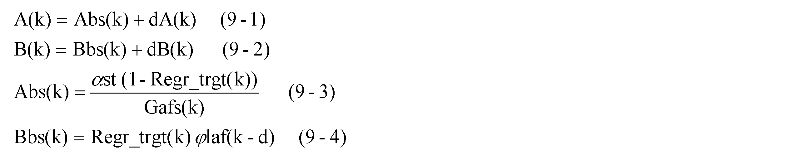

フィードバック用同定器36は、上述の噴射量-センサ出力モデルを利用して、このモデルに含まれるモデルパラメータA,Bの値を、所定のタイミングで逐次同定する。
ストイキ運転モードコントローラ37は、フィードバック用同定器36によってその値が同定されたモデルパラメータA,Bを利用してストイキフィードバック制御時用の噴射量Gfuel_stを算出する。
また、LAF遅れ補償用同定器35は、上述のポート当量比-センサ出力モデルを利用して、このモデルに含まれる応答遅れ係数Cの値を逐次同定する。なお、図9に示すように、LAF遅れ補償用同定器35は、上記フィードバック用同定器36とは別に構成されており、フィードバック用同定器36から独立した演算によって、応答遅れ係数Cの値を同定することが可能になっている。


この場合、先ず、モデルパラメータA,Bを成分とするモデルパラメータベクトルΘを下記式(13)で定義する。



また、行列Kpは、モデルパラメータ更新ゲイン行列であり、下記式(16-1)で定義される。この式(16-1)中、行列Pは、適応ゲイン行列であり、下記式(16-3)で定義される。適応ゲイン行列Pの対角成分p1,p2は、それぞれ、正の値に設定される。また、ベクトルζは、入出力ベクトルであり、下記式(16-2)で定義される。
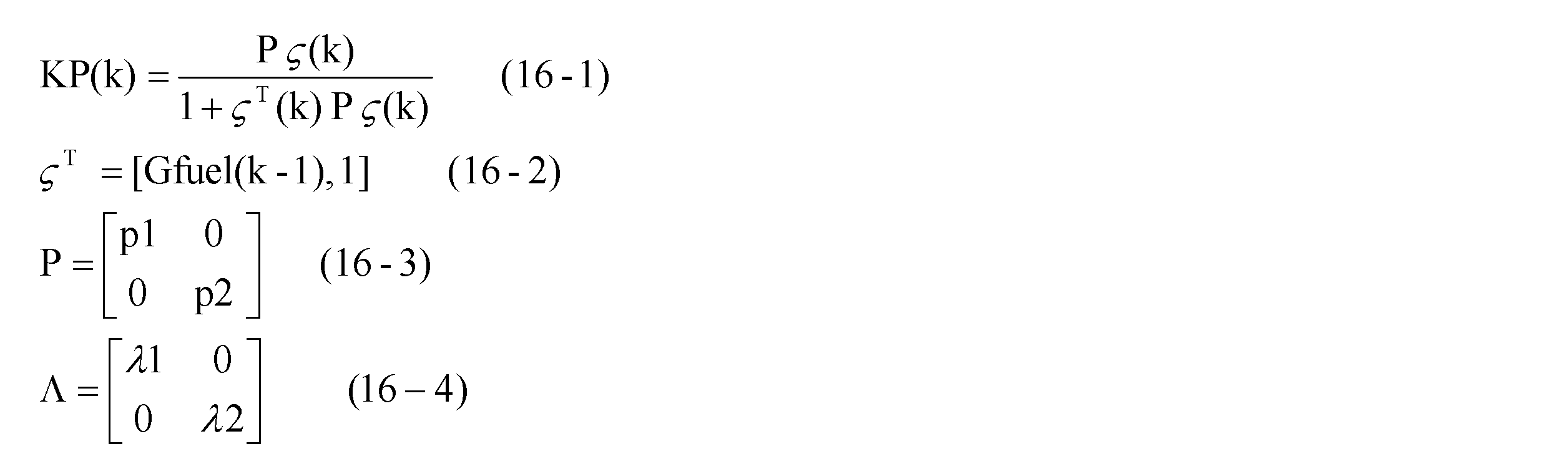


図11は、適応ストイキコントローラ34によって実現される当量比制御の概念を説明するための図である。図11には、上段から順に、シリンダに導入されるガスの内訳、Inert-EGR率[%]、フィードバック用同定器36によって同定されるモデルパラメータベクトルΘ及びΘbs、燃料噴射量、LAFセンサ出力、及びNOx浄化率[%]を示す。
LAF遅れ補償用同定器35は、適応ストイキコントローラ33において利用される燃料噴射量-センサ出力モデルに含まれる遅れ係数C(上記式(10)参照)の値を同定する。先ず、この遅れ係数Cの誤差が、上記適応ストイキコントローラ33の制御結果に及ぼす影響について説明する。




図16に示すように、0~所定の上限値まで変化する排ガスボリュームに対し、各重み関数ωiの定義域が重複するように、かつ、重み関数ωiの値の和が全ての排ガスボリュームに対して等しくなるように設定される。また、基準遅れ係数Cbsが大きく変化する領域では、その誤差も大きく変化すると考えられる。このため、図16に示すように、基準遅れ係数Cbsが大きく変化する領域(排ガスボリュームが小さな領域)では、重み関数ωiは密になるように設定することが好ましい。



図19は、上述の燃料噴射制御によって発生し得るトルク段差を説明する図である。より具体的には、図19は、ストイキ運転モード中において、ストイキフィードバック制御を開始する前と後で、同じ噴射態様で燃料を噴射した場合に生じる可能性のあるトルク段差を模式的に示す図である。
上述のように、ストイキフィードバック制御を開始すると、燃料噴射量Gfuelは、フィードフォワード噴射量Gfuel_st_ffからストイキフィードバック制御時用の噴射量Gfuel_stに持ち替えられる。この際、噴射量Gfuel_stは、LAFセンサの出力を、ストイキよりリーン側からストイキに近づけるように、フィードフォワード噴射量Gfuel_st_ffよりも大きくなる。このため、ストイキフィードバック制御の開始の前後で同じ態様で燃料を噴射すると、図示するような意図しないトルク段差が発生する場合がある。以下では、このようなトルク段差を解消するための噴射パターン制御の手順について説明する。
先ず、ドライバの要求駆動力Tdrvを実現するように、かつ、燃料噴射制御で定められた燃料噴射量Gfuelを分割するようにメイン噴射量Gf_m及びアフター噴射量Gf_aを決定するため、二つの噴射量Gf_m,Gf_aに対し、下記の2つの恒等式を課す。下記式(26-1)において、係数Ita_m(k),Ita_a(k)は、それぞれメイン噴射及びアフター噴射のトルク変換効率に相当し、各々の噴射タイミングを引数として図24に示すマップを検索することで算出される。






先ず、リーン運転モードからストイキ運転モードへ切り換ると、メイン噴射に加えてアフター噴射が実行される。その後、ストイキフィードバック制御が開始すると、LAFセンサの出力がリーン側からストイキになるように、燃料噴射量が増量される。この際、当量比がストイキになるように定められた燃料噴射量は、上記式(26-1)~(32)に従ってアフター噴射量とメイン噴射量とに適切に分割される。これによって、直下触媒で三元浄化反応が進行するような当量比に制御しつつ、トルク段差が発生するのを抑制することができる。
以下、上記実施形態のフィードバック用同定器の変形例について説明する。
図27は、上記実施形態のフィードバック用同定器32における演算(上記式(11-1)~式(16-4)参照)の手順を示すブロック図である。
フィードバック用同定器32は、燃料噴射量Gfuel(k-1)及び基準値Bbs(上記式(9-4)参照)を入力として、モデルパラメータA,B及び応答遅れ係数Cを含む噴射量-センサ出力モデルを利用した式(11-1)及び(11-2)によって、LAFセンサ出力の推定値φlaf_hat(k)を算出するLAFセンサ出力推定演算部321と、推定値φlaf_hat(k)とLAFセンサの出力値φlaf(k)との同定誤差E_id(k)(式(12)参照)が最小になるように2つのモデルパラメータの値A(k),B(k)を、上記式(13)~(16-4)を参照して説明した手順により逐次同定する同定演算部322と、を含んで構成される。





また、行列Kp’は、モデルパラメータ更新ゲイン行列であり、下記式(38-1)で定義される。この式(38-1)中、行列P’は、適応ゲイン行列であり、下記式(38-2)で定義される。適応ゲイン行列P’の対角成分p1’,p2’は、それぞれ、正の値に設定される。



11…排気通路
2…排気浄化システム
21…LAFセンサ(排ガスセンサ)
3…ECU(制御装置)
31…燃料噴射量算出部
32…リーン運転モードコントローラ
34…適応フィードバックコントローラ
35…LAF遅れ補償用同定器(第2同定部)
36…フィードバック同定器(第1同定部)
37…ストイキ運転モードコントローラ(コントローラ)
4…触媒浄化装置
Claims (6)
- 内燃機関の排ガスの当量比を検出する排ガスセンサの出力に基づいて、前記機関の混合気の当量比を制御する内燃機関の制御装置であって、
前記機関の燃料噴射量に関するパラメータから前記排ガスセンサの出力に関するパラメータまでの系を、第1モデルパラメータ及び第2モデルパラメータを含むモデル式によって第1モデルとしてモデル化するとともに、前記第1モデルパラメータの値を逐次同定する第1同定部と、
前記第1モデルのモデル式を利用して算出されるパラメータの値から前記排ガスセンサの出力までの系を、前記第2モデルパラメータを含むモデル式によって第2モデルとしてモデル化するとともに、前記排ガスセンサの出力に基づいて前記第2モデルパラメータの値を逐次同定する第2同定部と、
前記第1モデルパラメータに基づいて前記機関の混合気の当量比を制御するためのパラメータの値を決定するコントローラと、を備えることを特徴とする内燃機関の制御装置。 - 前記第2同定部は、少なくとも前記排ガスセンサの出力が変化している間に前記第2モデルパラメータの値を更新することを特徴とする請求項1に記載の内燃機関の制御装置。
- 前記第1同定部は、前記機関が特定の第1運転条件下にある間に前記第1モデルパラメータの値を更新し、
前記第2同定部は、前記機関が前記第1運転条件よりも広い第2運転条件下にある間に前記第2モデルパラメータの値を更新することを特徴とする請求項1又は2に記載の内燃機関の制御装置。 - 前記第2モデルパラメータは、前記排ガスセンサの検出遅れ特性に関するパラメータであり、
前記第2同定部によって同定された前記第2モデルパラメータの値と所定の異常判定閾値との比較によって、前記排ガスセンサの異常を判定する異常判定部をさらに備えることを特徴とする請求項1から3の何れかに記載の内燃機関の制御装置。 - 前記第1同定部は、
前記燃料噴射量を入力として、前記第1モデルパラメータ及び第2モデルパラメータを含む第1モデルのモデル式によって前記排ガスセンサの出力の推定値を算出するセンサ出力推定演算部と、
当該推定値と前記排ガスセンサの出力との誤差が最小になるように第1モデルパラメータの値を同定する同定演算部と、を備えることを特徴とする請求項1から4の何れかに記載の内燃機関の制御装置。 - 前記第2モデルパラメータは、前記排ガスセンサの検出遅れ特性に関するパラメータであり、
前記第1同定部は、
前記燃料噴射量に前記第2モデルパラメータによって特徴付けられる遅れ演算を行う遅れ演算部と、
前記遅れ演算部の出力に前記第1モデルパラメータによって特徴付けられる所定の演算を行うことによって前記排ガスセンサの出力の推定値を算出するセンサ出力推定演算部と、
当該推定値と前記排ガスセンサの出力との誤差が最小になるように第1モデルパラメータの値を同定する同定演算部と、を備えることを特徴とする請求項1から4の何れかに記載の内燃機関の制御装置。
Priority Applications (4)
| Application Number | Priority Date | Filing Date | Title |
|---|---|---|---|
| PCT/JP2012/068125 WO2014013553A1 (ja) | 2012-07-17 | 2012-07-17 | 内燃機関の制御装置 |
| US14/415,038 US10227940B2 (en) | 2012-07-17 | 2012-07-17 | Control device for internal combustion engine |
| DE112012006716.9T DE112012006716T5 (de) | 2012-07-17 | 2012-07-17 | Steuervorrichtung für Verbrennungsmotor |
| JP2014525588A JP5883140B2 (ja) | 2012-07-17 | 2012-07-17 | 内燃機関の制御装置 |
Applications Claiming Priority (1)
| Application Number | Priority Date | Filing Date | Title |
|---|---|---|---|
| PCT/JP2012/068125 WO2014013553A1 (ja) | 2012-07-17 | 2012-07-17 | 内燃機関の制御装置 |
Publications (1)
| Publication Number | Publication Date |
|---|---|
| WO2014013553A1 true WO2014013553A1 (ja) | 2014-01-23 |
Family
ID=49948408
Family Applications (1)
| Application Number | Title | Priority Date | Filing Date |
|---|---|---|---|
| PCT/JP2012/068125 Ceased WO2014013553A1 (ja) | 2012-07-17 | 2012-07-17 | 内燃機関の制御装置 |
Country Status (4)
| Country | Link |
|---|---|
| US (1) | US10227940B2 (ja) |
| JP (1) | JP5883140B2 (ja) |
| DE (1) | DE112012006716T5 (ja) |
| WO (1) | WO2014013553A1 (ja) |
Cited By (8)
| Publication number | Priority date | Publication date | Assignee | Title |
|---|---|---|---|---|
| JP2018009487A (ja) * | 2016-07-12 | 2018-01-18 | マツダ株式会社 | エンジンの排気浄化装置 |
| JP2018009482A (ja) * | 2016-07-12 | 2018-01-18 | マツダ株式会社 | エンジンの排気浄化装置 |
| JP2018009481A (ja) * | 2016-07-12 | 2018-01-18 | マツダ株式会社 | エンジンの排気浄化装置 |
| JP2018009484A (ja) * | 2016-07-12 | 2018-01-18 | マツダ株式会社 | エンジンの排気浄化装置 |
| JP2018009483A (ja) * | 2016-07-12 | 2018-01-18 | マツダ株式会社 | エンジンの排気浄化装置 |
| CN107654302A (zh) * | 2016-07-25 | 2018-02-02 | 通用汽车环球科技运作有限责任公司 | 燃料控制系统及延时补偿方法 |
| CN113915017A (zh) * | 2020-07-10 | 2022-01-11 | 纳博特斯克有限公司 | 发动机特性估计装置及方法、状态估计装置、存储介质 |
| KR20220057443A (ko) * | 2020-10-29 | 2022-05-09 | 가부시키가이샤 자판엔진코포레숀 | 주기 제어 시스템 |
Families Citing this family (3)
| Publication number | Priority date | Publication date | Assignee | Title |
|---|---|---|---|---|
| CN110100080B (zh) * | 2016-10-24 | 2022-05-24 | 巴斯夫公司 | 用于减少NOx的集成SCR催化剂和LNT |
| EP3339591B1 (en) * | 2016-12-21 | 2019-08-14 | Perkins Engines Company Limited | Control method and apparatus for a selective catalytic reduction system |
| DE102022101084B3 (de) * | 2022-01-18 | 2023-05-25 | Audi Aktiengesellschaft | Verfahren zum Betreiben einer Antriebseinrichtung für ein Kraftfahrzeug sowie entsprechende Antriebseinrichtung |
Citations (4)
| Publication number | Priority date | Publication date | Assignee | Title |
|---|---|---|---|---|
| JPH08234807A (ja) * | 1995-02-22 | 1996-09-13 | Mazda Motor Corp | 機器の制御装置 |
| JP2012088866A (ja) * | 2010-10-18 | 2012-05-10 | Honda Motor Co Ltd | 制御装置 |
| JP2012098989A (ja) * | 2010-11-04 | 2012-05-24 | Honda Motor Co Ltd | 制御装置 |
| JP2012127356A (ja) * | 2012-03-22 | 2012-07-05 | Toyota Motor Corp | 空燃比センサの異常診断装置 |
Family Cites Families (64)
| Publication number | Priority date | Publication date | Assignee | Title |
|---|---|---|---|---|
| JPH0650074B2 (ja) * | 1983-08-08 | 1994-06-29 | 株式会社日立製作所 | エンジンの燃料制御方法 |
| EP0518289B1 (en) * | 1991-06-10 | 1994-12-14 | Nippondenso Co., Ltd. | Apparatus for controlling speed of internal combustion engine |
| DE69333483T2 (de) * | 1992-07-03 | 2004-08-12 | Honda Giken Kogyo K.K. | Kraftstoffmesssteuersystem und Zylinderluftflussschätzungsmethode im Verbrennungsmotor |
| JP2750648B2 (ja) * | 1992-11-16 | 1998-05-13 | 本田技研工業株式会社 | 漸化式形式のパラメータ調整則を持つ適応制御器 |
| US5632261A (en) * | 1994-12-30 | 1997-05-27 | Honda Giken Kogyo Kabushiki Kaisha | Fuel metering control system for internal combustion engine |
| US5636621A (en) * | 1994-12-30 | 1997-06-10 | Honda Giken Kogyo Kabushiki Kaisha | Fuel metering control system for internal combustion engine |
| US5651341A (en) * | 1995-02-08 | 1997-07-29 | Mazda Motor Corporation | Control system for dynamically operative apparatuses |
| JP3510021B2 (ja) * | 1995-09-29 | 2004-03-22 | 松下電器産業株式会社 | 内燃機関の空燃比制御装置 |
| US5852930A (en) * | 1996-04-05 | 1998-12-29 | Honda Giken Kogyo Kabushiki Kaisha | Air-fuel ratio control system for internal combustion engines |
| JP3300598B2 (ja) * | 1996-04-05 | 2002-07-08 | 本田技研工業株式会社 | 内燃機関の空燃比制御装置 |
| JP3373724B2 (ja) * | 1996-04-05 | 2003-02-04 | 本田技研工業株式会社 | 内燃機関の空燃比制御装置 |
| JP3299109B2 (ja) * | 1996-04-05 | 2002-07-08 | 本田技研工業株式会社 | スライディングモード制御方法 |
| JP3261038B2 (ja) * | 1996-04-05 | 2002-02-25 | 本田技研工業株式会社 | 内燃機関の空燃比制御装置 |
| JP3805840B2 (ja) * | 1996-09-25 | 2006-08-09 | 富士重工業株式会社 | エンジンの制御装置 |
| JP3658115B2 (ja) * | 1996-11-20 | 2005-06-08 | 本田技研工業株式会社 | 内燃機関の排気浄化装置 |
| JP3304844B2 (ja) * | 1997-08-29 | 2002-07-22 | 本田技研工業株式会社 | プラントの制御装置 |
| JP3331159B2 (ja) * | 1997-09-16 | 2002-10-07 | 本田技研工業株式会社 | プラントの制御装置 |
| JP3354088B2 (ja) * | 1997-09-16 | 2002-12-09 | 本田技研工業株式会社 | 内燃機関の排気系の空燃比制御装置 |
| JP3592519B2 (ja) * | 1997-09-16 | 2004-11-24 | 本田技研工業株式会社 | 内燃機関の排気系の空燃比制御装置及びプラントの制御装置 |
| JPH11159377A (ja) * | 1997-12-01 | 1999-06-15 | Hitachi Ltd | エンジン制御装置 |
| US6082345A (en) * | 1997-12-05 | 2000-07-04 | Honda Giken Kogyo Kabushiki Kaisha | Air-fuel ratio control system for internal combustion engines |
| JP3484074B2 (ja) * | 1998-05-13 | 2004-01-06 | 本田技研工業株式会社 | プラントの制御装置 |
| WO2000004282A1 (en) * | 1998-07-17 | 2000-01-27 | Honda Giken Kogyo Kabushiki Kaisha | Method of judging deterioration of emission gas control catalyst device |
| JP3621839B2 (ja) * | 1998-12-17 | 2005-02-16 | 本田技研工業株式会社 | プラントの制御装置 |
| US6292739B1 (en) * | 1998-12-17 | 2001-09-18 | Honda Giken Kogyo Kabushiki Kaisha | Air-fuel ratio control system for internal combustion engine |
| JP3484088B2 (ja) * | 1998-12-17 | 2004-01-06 | 本田技研工業株式会社 | プラントの制御装置 |
| JP4265704B2 (ja) * | 1999-04-14 | 2009-05-20 | 本田技研工業株式会社 | 内燃機関の空燃比制御装置及びプラントの制御装置 |
| JP2001073746A (ja) * | 1999-09-03 | 2001-03-21 | Honda Motor Co Ltd | 排ガス吸着材の劣化状態評価方法 |
| JP3610839B2 (ja) * | 1999-09-27 | 2005-01-19 | 株式会社デンソー | 内燃機関の空燃比制御装置 |
| JP3655145B2 (ja) * | 1999-10-08 | 2005-06-02 | 本田技研工業株式会社 | 多気筒内燃機関の空燃比制御装置 |
| JP3655146B2 (ja) * | 1999-10-08 | 2005-06-02 | 本田技研工業株式会社 | 多気筒内燃機関の空燃比制御装置 |
| JP3782269B2 (ja) * | 1999-11-12 | 2006-06-07 | 本田技研工業株式会社 | 内燃機関の空燃比制御装置 |
| JP3688533B2 (ja) * | 1999-11-12 | 2005-08-31 | 本田技研工業株式会社 | 排ガス浄化用触媒装置の劣化状態評価方法 |
| JP4312325B2 (ja) * | 1999-12-28 | 2009-08-12 | 本田技研工業株式会社 | 排ガス浄化用触媒装置の劣化状態評価方法 |
| US6591822B2 (en) * | 2000-06-20 | 2003-07-15 | Denso Corporation | Air-fuel ratio controller of internal combustion engines |
| JP3758134B2 (ja) * | 2000-10-23 | 2006-03-22 | 株式会社デンソー | 内燃機関の制御装置 |
| MY138476A (en) * | 2001-02-01 | 2009-06-30 | Honda Motor Co Ltd | Apparatus for and method of controlling plant |
| JP4581038B2 (ja) * | 2001-02-05 | 2010-11-17 | 株式会社デンソー | 内燃機関の燃料噴射量制御装置 |
| JP2002318604A (ja) * | 2001-04-20 | 2002-10-31 | Unisia Jecs Corp | 制御装置 |
| JP4437626B2 (ja) * | 2001-05-14 | 2010-03-24 | 本田技研工業株式会社 | 内燃機関の空燃比制御装置 |
| WO2002103183A1 (fr) * | 2001-06-19 | 2002-12-27 | Honda Giken Kogyo Kabushiki Kaisha | Dispositif, procede, et support d'enregistrement de programme de regulation du rapport du melange air-carburant |
| JP4490000B2 (ja) * | 2001-06-19 | 2010-06-23 | 本田技研工業株式会社 | 内燃機関の空燃比制御装置 |
| JP3965947B2 (ja) * | 2001-07-25 | 2007-08-29 | 日産自動車株式会社 | エンジンの空燃比制御装置 |
| US6619277B2 (en) * | 2001-07-12 | 2003-09-16 | Nissan Motor Co., Ltd. | Engine air-fuel ratio control |
| JP3904923B2 (ja) * | 2001-12-28 | 2007-04-11 | 本田技研工業株式会社 | 制御装置 |
| JP3922980B2 (ja) * | 2001-07-25 | 2007-05-30 | 本田技研工業株式会社 | 制御装置 |
| JP4430270B2 (ja) * | 2001-08-06 | 2010-03-10 | 本田技研工業株式会社 | プラントの制御装置及び内燃機関の空燃比制御装置 |
| US20030101975A1 (en) * | 2001-11-29 | 2003-06-05 | Hitachi Unisia Automotive, Ltd. | Air-fuel ratio control apparatus of internal combustion engine and method thereof |
| US6785601B2 (en) * | 2001-12-18 | 2004-08-31 | Hitachi Unisia Automotive, Ltd. | Air-fuel ratio control apparatus of internal combustion engine and method thereof |
| JP3880861B2 (ja) * | 2002-01-22 | 2007-02-14 | 本田技研工業株式会社 | 内燃機関の空燃比制御装置 |
| JP3973922B2 (ja) * | 2002-02-15 | 2007-09-12 | 本田技研工業株式会社 | 制御装置 |
| JP4064148B2 (ja) * | 2002-05-16 | 2008-03-19 | 本田技研工業株式会社 | 素子温を利用して排ガスセンサの故障を検出する装置 |
| JP3942970B2 (ja) * | 2002-07-05 | 2007-07-11 | 本田技研工業株式会社 | プラントの制御装置 |
| JP3926703B2 (ja) * | 2002-08-08 | 2007-06-06 | 本田技研工業株式会社 | 制御装置 |
| JP3824983B2 (ja) * | 2002-09-04 | 2006-09-20 | 本田技研工業株式会社 | リーン運転の際に同定器の演算を停止する内燃機関の空燃比制御装置 |
| JP4028334B2 (ja) * | 2002-09-12 | 2007-12-26 | 本田技研工業株式会社 | 制御装置 |
| JP4030010B2 (ja) * | 2002-11-08 | 2008-01-09 | 本田技研工業株式会社 | 排ガスセンサの劣化判定装置 |
| JP3998136B2 (ja) * | 2002-11-28 | 2007-10-24 | 本田技研工業株式会社 | 内燃機関の空燃比制御装置 |
| JP4184058B2 (ja) * | 2002-12-05 | 2008-11-19 | 本田技研工業株式会社 | 制御装置 |
| JP4391789B2 (ja) * | 2003-10-03 | 2009-12-24 | 本田技研工業株式会社 | モデルパラメータを部分的に同定する同定器を備えた、プラントを制御する制御装置 |
| JP4205030B2 (ja) * | 2003-10-06 | 2009-01-07 | 本田技研工業株式会社 | 内燃機関の空燃比制御装置 |
| JP4919945B2 (ja) * | 2007-12-12 | 2012-04-18 | 日立オートモティブシステムズ株式会社 | エンジンのスライディングモード制御による空燃比制御方法、及びその方法を備えた燃料制御装置 |
| JP4997177B2 (ja) | 2008-06-09 | 2012-08-08 | 本田技研工業株式会社 | 内燃機関の排ガス浄化装置 |
| DE112012006719T5 (de) * | 2012-07-17 | 2015-09-10 | Delphi International Operations Luxembourg S.À R.L. | Abgasreinigungssystem für Verbrennungsmotor |
-
2012
- 2012-07-17 JP JP2014525588A patent/JP5883140B2/ja not_active Expired - Fee Related
- 2012-07-17 WO PCT/JP2012/068125 patent/WO2014013553A1/ja not_active Ceased
- 2012-07-17 DE DE112012006716.9T patent/DE112012006716T5/de not_active Withdrawn
- 2012-07-17 US US14/415,038 patent/US10227940B2/en active Active
Patent Citations (4)
| Publication number | Priority date | Publication date | Assignee | Title |
|---|---|---|---|---|
| JPH08234807A (ja) * | 1995-02-22 | 1996-09-13 | Mazda Motor Corp | 機器の制御装置 |
| JP2012088866A (ja) * | 2010-10-18 | 2012-05-10 | Honda Motor Co Ltd | 制御装置 |
| JP2012098989A (ja) * | 2010-11-04 | 2012-05-24 | Honda Motor Co Ltd | 制御装置 |
| JP2012127356A (ja) * | 2012-03-22 | 2012-07-05 | Toyota Motor Corp | 空燃比センサの異常診断装置 |
Cited By (13)
| Publication number | Priority date | Publication date | Assignee | Title |
|---|---|---|---|---|
| US10309328B2 (en) | 2016-07-12 | 2019-06-04 | Mazda Motor Corporation | Exhaust emission control system of engine |
| JP2018009482A (ja) * | 2016-07-12 | 2018-01-18 | マツダ株式会社 | エンジンの排気浄化装置 |
| JP2018009481A (ja) * | 2016-07-12 | 2018-01-18 | マツダ株式会社 | エンジンの排気浄化装置 |
| JP2018009484A (ja) * | 2016-07-12 | 2018-01-18 | マツダ株式会社 | エンジンの排気浄化装置 |
| JP2018009483A (ja) * | 2016-07-12 | 2018-01-18 | マツダ株式会社 | エンジンの排気浄化装置 |
| JP2018009487A (ja) * | 2016-07-12 | 2018-01-18 | マツダ株式会社 | エンジンの排気浄化装置 |
| CN107654302A (zh) * | 2016-07-25 | 2018-02-02 | 通用汽车环球科技运作有限责任公司 | 燃料控制系统及延时补偿方法 |
| CN107654302B (zh) * | 2016-07-25 | 2021-07-13 | 通用汽车环球科技运作有限责任公司 | 燃料控制系统及延时补偿方法 |
| CN113915017A (zh) * | 2020-07-10 | 2022-01-11 | 纳博特斯克有限公司 | 发动机特性估计装置及方法、状态估计装置、存储介质 |
| JP2022015997A (ja) * | 2020-07-10 | 2022-01-21 | ナブテスコ株式会社 | エンジン特性推定装置、エンジン特性推定方法、エンジン特性推定プログラム、およびエンジン状態推定装置 |
| CN113915017B (zh) * | 2020-07-10 | 2025-04-29 | 纳博特斯克有限公司 | 发动机特性估计装置及方法、状态估计装置、存储介质 |
| KR20220057443A (ko) * | 2020-10-29 | 2022-05-09 | 가부시키가이샤 자판엔진코포레숀 | 주기 제어 시스템 |
| KR102566082B1 (ko) | 2020-10-29 | 2023-08-10 | 가부시키가이샤 자판엔진코포레숀 | 주기 제어 시스템 |
Also Published As
| Publication number | Publication date |
|---|---|
| US10227940B2 (en) | 2019-03-12 |
| DE112012006716T5 (de) | 2015-09-10 |
| JPWO2014013553A1 (ja) | 2016-06-23 |
| US20150211427A1 (en) | 2015-07-30 |
| JP5883140B2 (ja) | 2016-03-09 |
Similar Documents
| Publication | Publication Date | Title |
|---|---|---|
| JP5883140B2 (ja) | 内燃機関の制御装置 | |
| JP5824153B2 (ja) | 内燃機関の排気浄化システム | |
| JP5093406B1 (ja) | 内燃機関の制御装置 | |
| JP3963130B2 (ja) | 触媒劣化判定装置 | |
| US8965664B2 (en) | Controller for plant | |
| JP4957559B2 (ja) | 内燃機関の空燃比制御装置 | |
| JP5366988B2 (ja) | 内燃機関の排気浄化システム | |
| KR100773276B1 (ko) | 내연 기관의 공연비 제어 장치 | |
| US8033097B2 (en) | Exhaust control device for an internal combustion engine | |
| JP3922091B2 (ja) | 内燃機関の空燃比制御装置 | |
| JP2009299557A (ja) | 触媒の劣化判定装置 | |
| CN101139953A (zh) | 用于控制贫燃Nox捕集器再生的系统 | |
| US10677136B2 (en) | Internal combustion engine control device | |
| US20180017008A1 (en) | Systems and methods for estimating exhaust pressure | |
| JP2012127305A (ja) | 内燃機関の空燃比制御装置 | |
| JP5273224B2 (ja) | 内燃機関の空燃比制御装置 | |
| JP4449603B2 (ja) | 内燃機関の燃料噴射制御装置 | |
| JP5308875B2 (ja) | 内燃機関の排ガス浄化装置 | |
| JP2009197683A (ja) | 内燃機関の空燃比制御装置 | |
| JP2004251123A (ja) | 内燃機関の排気浄化装置 | |
| CN103874840A (zh) | 用于控制内燃机的方法 | |
| JP2008215106A (ja) | 内燃機関の空燃比制御装置 | |
| JP2004092472A (ja) | 内燃機関の排気浄化装置 |
Legal Events
| Date | Code | Title | Description |
|---|---|---|---|
| 121 | Ep: the epo has been informed by wipo that ep was designated in this application |
Ref document number: 12881372 Country of ref document: EP Kind code of ref document: A1 |
|
| ENP | Entry into the national phase |
Ref document number: 2014525588 Country of ref document: JP Kind code of ref document: A |
|
| WWE | Wipo information: entry into national phase |
Ref document number: 14415038 Country of ref document: US |
|
| WWE | Wipo information: entry into national phase |
Ref document number: 112012006716 Country of ref document: DE Ref document number: 1120120067169 Country of ref document: DE |
|
| 122 | Ep: pct application non-entry in european phase |
Ref document number: 12881372 Country of ref document: EP Kind code of ref document: A1 |