WO2013175778A1 - Dispositif électronique et dispositif formant plaque - Google Patents
Dispositif électronique et dispositif formant plaque Download PDFInfo
- Publication number
- WO2013175778A1 WO2013175778A1 PCT/JP2013/003245 JP2013003245W WO2013175778A1 WO 2013175778 A1 WO2013175778 A1 WO 2013175778A1 JP 2013003245 W JP2013003245 W JP 2013003245W WO 2013175778 A1 WO2013175778 A1 WO 2013175778A1
- Authority
- WO
- WIPO (PCT)
- Prior art keywords
- piezoelectric element
- panel
- control unit
- sound
- electronic device
- Prior art date
Links
- 238000001514 detection method Methods 0.000 claims description 209
- 230000006870 function Effects 0.000 claims description 178
- 238000000034 method Methods 0.000 claims description 155
- 230000008569 process Effects 0.000 claims description 140
- 230000035807 sensation Effects 0.000 claims description 138
- 238000012545 processing Methods 0.000 claims description 101
- 230000008602 contraction Effects 0.000 claims description 33
- 238000004891 communication Methods 0.000 description 48
- 230000005236 sound signal Effects 0.000 description 40
- 238000010586 diagram Methods 0.000 description 27
- 125000002066 L-histidyl group Chemical group [H]N1C([H])=NC(C([H])([H])[C@](C(=O)[*])([H])N([H])[H])=C1[H] 0.000 description 25
- 210000000845 cartilage Anatomy 0.000 description 23
- 239000000853 adhesive Substances 0.000 description 21
- 230000001070 adhesive effect Effects 0.000 description 20
- 238000005452 bending Methods 0.000 description 18
- 239000007788 liquid Substances 0.000 description 16
- 229920005989 resin Polymers 0.000 description 16
- 239000011347 resin Substances 0.000 description 16
- 210000000883 ear external Anatomy 0.000 description 15
- 230000005540 biological transmission Effects 0.000 description 13
- 230000003287 optical effect Effects 0.000 description 13
- 230000001133 acceleration Effects 0.000 description 11
- NIXOWILDQLNWCW-UHFFFAOYSA-N acrylic acid group Chemical group C(C=C)(=O)O NIXOWILDQLNWCW-UHFFFAOYSA-N 0.000 description 11
- 239000011521 glass Substances 0.000 description 11
- HFGPZNIAWCZYJU-UHFFFAOYSA-N lead zirconate titanate Chemical compound [O-2].[O-2].[O-2].[O-2].[O-2].[Ti+4].[Zr+4].[Pb+2] HFGPZNIAWCZYJU-UHFFFAOYSA-N 0.000 description 10
- 229910052451 lead zirconate titanate Inorganic materials 0.000 description 10
- 239000002184 metal Substances 0.000 description 10
- 229920000544 Gore-Tex Polymers 0.000 description 8
- 230000008859 change Effects 0.000 description 8
- 210000003027 ear inner Anatomy 0.000 description 8
- 210000000959 ear middle Anatomy 0.000 description 8
- 230000003014 reinforcing effect Effects 0.000 description 8
- 210000004872 soft tissue Anatomy 0.000 description 8
- 239000000758 substrate Substances 0.000 description 8
- 229920001187 thermosetting polymer Polymers 0.000 description 8
- 238000013459 approach Methods 0.000 description 6
- 239000000919 ceramic Substances 0.000 description 5
- 239000000470 constituent Substances 0.000 description 5
- 230000008878 coupling Effects 0.000 description 5
- 238000010168 coupling process Methods 0.000 description 5
- 238000005859 coupling reaction Methods 0.000 description 5
- 230000000694 effects Effects 0.000 description 5
- 239000000463 material Substances 0.000 description 5
- 239000003973 paint Substances 0.000 description 5
- 239000010453 quartz Substances 0.000 description 5
- VYPSYNLAJGMNEJ-UHFFFAOYSA-N silicon dioxide Inorganic materials O=[Si]=O VYPSYNLAJGMNEJ-UHFFFAOYSA-N 0.000 description 5
- 230000002238 attenuated effect Effects 0.000 description 4
- 239000004973 liquid crystal related substance Substances 0.000 description 3
- 230000015541 sensory perception of touch Effects 0.000 description 3
- 229920003002 synthetic resin Polymers 0.000 description 3
- 239000000057 synthetic resin Substances 0.000 description 3
- 230000005674 electromagnetic induction Effects 0.000 description 2
- 238000012986 modification Methods 0.000 description 2
- 230000004048 modification Effects 0.000 description 2
- 238000010897 surface acoustic wave method Methods 0.000 description 2
- 239000002699 waste material Substances 0.000 description 2
- 230000000295 complement effect Effects 0.000 description 1
- 238000013016 damping Methods 0.000 description 1
- 230000007257 malfunction Effects 0.000 description 1
Images


Classifications
-
- G—PHYSICS
- G06—COMPUTING; CALCULATING OR COUNTING
- G06F—ELECTRIC DIGITAL DATA PROCESSING
- G06F3/00—Input arrangements for transferring data to be processed into a form capable of being handled by the computer; Output arrangements for transferring data from processing unit to output unit, e.g. interface arrangements
- G06F3/01—Input arrangements or combined input and output arrangements for interaction between user and computer
- G06F3/03—Arrangements for converting the position or the displacement of a member into a coded form
- G06F3/041—Digitisers, e.g. for touch screens or touch pads, characterised by the transducing means
-
- G—PHYSICS
- G06—COMPUTING; CALCULATING OR COUNTING
- G06F—ELECTRIC DIGITAL DATA PROCESSING
- G06F3/00—Input arrangements for transferring data to be processed into a form capable of being handled by the computer; Output arrangements for transferring data from processing unit to output unit, e.g. interface arrangements
- G06F3/01—Input arrangements or combined input and output arrangements for interaction between user and computer
- G06F3/016—Input arrangements with force or tactile feedback as computer generated output to the user
-
- G—PHYSICS
- G06—COMPUTING; CALCULATING OR COUNTING
- G06F—ELECTRIC DIGITAL DATA PROCESSING
- G06F3/00—Input arrangements for transferring data to be processed into a form capable of being handled by the computer; Output arrangements for transferring data from processing unit to output unit, e.g. interface arrangements
- G06F3/01—Input arrangements or combined input and output arrangements for interaction between user and computer
- G06F3/048—Interaction techniques based on graphical user interfaces [GUI]
- G06F3/0487—Interaction techniques based on graphical user interfaces [GUI] using specific features provided by the input device, e.g. functions controlled by the rotation of a mouse with dual sensing arrangements, or of the nature of the input device, e.g. tap gestures based on pressure sensed by a digitiser
- G06F3/0488—Interaction techniques based on graphical user interfaces [GUI] using specific features provided by the input device, e.g. functions controlled by the rotation of a mouse with dual sensing arrangements, or of the nature of the input device, e.g. tap gestures based on pressure sensed by a digitiser using a touch-screen or digitiser, e.g. input of commands through traced gestures
-
- H—ELECTRICITY
- H04—ELECTRIC COMMUNICATION TECHNIQUE
- H04M—TELEPHONIC COMMUNICATION
- H04M1/00—Substation equipment, e.g. for use by subscribers
- H04M1/02—Constructional features of telephone sets
- H04M1/03—Constructional features of telephone transmitters or receivers, e.g. telephone hand-sets
-
- H—ELECTRICITY
- H04—ELECTRIC COMMUNICATION TECHNIQUE
- H04R—LOUDSPEAKERS, MICROPHONES, GRAMOPHONE PICK-UPS OR LIKE ACOUSTIC ELECTROMECHANICAL TRANSDUCERS; DEAF-AID SETS; PUBLIC ADDRESS SYSTEMS
- H04R7/00—Diaphragms for electromechanical transducers; Cones
- H04R7/02—Diaphragms for electromechanical transducers; Cones characterised by the construction
- H04R7/04—Plane diaphragms
- H04R7/045—Plane diaphragms using the distributed mode principle, i.e. whereby the acoustic radiation is emanated from uniformly distributed free bending wave vibration induced in a stiff panel and not from pistonic motion
-
- G—PHYSICS
- G06—COMPUTING; CALCULATING OR COUNTING
- G06F—ELECTRIC DIGITAL DATA PROCESSING
- G06F2203/00—Indexing scheme relating to G06F3/00 - G06F3/048
- G06F2203/01—Indexing scheme relating to G06F3/01
- G06F2203/014—Force feedback applied to GUI
-
- G—PHYSICS
- G06—COMPUTING; CALCULATING OR COUNTING
- G06F—ELECTRIC DIGITAL DATA PROCESSING
- G06F2203/00—Indexing scheme relating to G06F3/00 - G06F3/048
- G06F2203/041—Indexing scheme relating to G06F3/041 - G06F3/045
- G06F2203/04105—Pressure sensors for measuring the pressure or force exerted on the touch surface without providing the touch position
-
- H—ELECTRICITY
- H04—ELECTRIC COMMUNICATION TECHNIQUE
- H04M—TELEPHONIC COMMUNICATION
- H04M1/00—Substation equipment, e.g. for use by subscribers
- H04M1/02—Constructional features of telephone sets
- H04M1/0202—Portable telephone sets, e.g. cordless phones, mobile phones or bar type handsets
- H04M1/026—Details of the structure or mounting of specific components
- H04M1/0266—Details of the structure or mounting of specific components for a display module assembly
-
- H—ELECTRICITY
- H04—ELECTRIC COMMUNICATION TECHNIQUE
- H04R—LOUDSPEAKERS, MICROPHONES, GRAMOPHONE PICK-UPS OR LIKE ACOUSTIC ELECTROMECHANICAL TRANSDUCERS; DEAF-AID SETS; PUBLIC ADDRESS SYSTEMS
- H04R17/00—Piezoelectric transducers; Electrostrictive transducers
-
- H—ELECTRICITY
- H04—ELECTRIC COMMUNICATION TECHNIQUE
- H04R—LOUDSPEAKERS, MICROPHONES, GRAMOPHONE PICK-UPS OR LIKE ACOUSTIC ELECTROMECHANICAL TRANSDUCERS; DEAF-AID SETS; PUBLIC ADDRESS SYSTEMS
- H04R2400/00—Loudspeakers
- H04R2400/03—Transducers capable of generating both sound as well as tactile vibration, e.g. as used in cellular phones
-
- H—ELECTRICITY
- H04—ELECTRIC COMMUNICATION TECHNIQUE
- H04R—LOUDSPEAKERS, MICROPHONES, GRAMOPHONE PICK-UPS OR LIKE ACOUSTIC ELECTROMECHANICAL TRANSDUCERS; DEAF-AID SETS; PUBLIC ADDRESS SYSTEMS
- H04R2440/00—Bending wave transducers covered by H04R, not provided for in its groups
- H04R2440/05—Aspects relating to the positioning and way or means of mounting of exciters to resonant bending wave panels
-
- H—ELECTRICITY
- H04—ELECTRIC COMMUNICATION TECHNIQUE
- H04R—LOUDSPEAKERS, MICROPHONES, GRAMOPHONE PICK-UPS OR LIKE ACOUSTIC ELECTROMECHANICAL TRANSDUCERS; DEAF-AID SETS; PUBLIC ADDRESS SYSTEMS
- H04R2460/00—Details of hearing devices, i.e. of ear- or headphones covered by H04R1/10 or H04R5/033 but not provided for in any of their subgroups, or of hearing aids covered by H04R25/00 but not provided for in any of its subgroups
- H04R2460/03—Aspects of the reduction of energy consumption in hearing devices
-
- H—ELECTRICITY
- H04—ELECTRIC COMMUNICATION TECHNIQUE
- H04R—LOUDSPEAKERS, MICROPHONES, GRAMOPHONE PICK-UPS OR LIKE ACOUSTIC ELECTROMECHANICAL TRANSDUCERS; DEAF-AID SETS; PUBLIC ADDRESS SYSTEMS
- H04R2460/00—Details of hearing devices, i.e. of ear- or headphones covered by H04R1/10 or H04R5/033 but not provided for in any of their subgroups, or of hearing aids covered by H04R25/00 but not provided for in any of its subgroups
- H04R2460/13—Hearing devices using bone conduction transducers
-
- H—ELECTRICITY
- H04—ELECTRIC COMMUNICATION TECHNIQUE
- H04R—LOUDSPEAKERS, MICROPHONES, GRAMOPHONE PICK-UPS OR LIKE ACOUSTIC ELECTROMECHANICAL TRANSDUCERS; DEAF-AID SETS; PUBLIC ADDRESS SYSTEMS
- H04R2499/00—Aspects covered by H04R or H04S not otherwise provided for in their subgroups
- H04R2499/10—General applications
- H04R2499/11—Transducers incorporated or for use in hand-held devices, e.g. mobile phones, PDA's, camera's
-
- H—ELECTRICITY
- H04—ELECTRIC COMMUNICATION TECHNIQUE
- H04R—LOUDSPEAKERS, MICROPHONES, GRAMOPHONE PICK-UPS OR LIKE ACOUSTIC ELECTROMECHANICAL TRANSDUCERS; DEAF-AID SETS; PUBLIC ADDRESS SYSTEMS
- H04R2499/00—Aspects covered by H04R or H04S not otherwise provided for in their subgroups
- H04R2499/10—General applications
- H04R2499/15—Transducers incorporated in visual displaying devices, e.g. televisions, computer displays, laptops
Definitions
- the present application includes Japanese Patent Application No. 2012-116880 (filed on May 22, 2012), Japanese Patent Application No. 2012-116885 (filed on May 22, 2012), Japanese Patent Application No. 2012-116887 (2012). Filed on May 22, 2012), Japanese Patent Application No. 2012-116906 (filed on May 22, 2012), Japanese Patent Application No. 2012-116908 (filed on May 22, 2012), Japanese Patent Application 2012- 116922 (filed on May 22, 2012), Japanese Patent Application No. 2012-117005 (filed on May 22, 2012), and Japanese Patent Application No. 2012-1117023 (filed on May 22, 2012)
- the entire disclosure of that application is hereby incorporated by reference.
- the present invention relates to an electronic device and a panel device provided with a panel such as a touch panel. More specifically, the present invention relates to an electronic device that performs predetermined processing such as executing application software (hereinafter referred to as an application) based on an operation on a touch sensor.
- an application application software
- a user's operation is detected in a mobile terminal such as a smartphone, an information device such as a tablet PC, a calculator, and a ticket vending machine, a home appliance such as a microwave oven, a television, and a lighting fixture, and an industrial device (FA device).
- a mobile terminal such as a smartphone
- an information device such as a tablet PC, a calculator, and a ticket vending machine
- a home appliance such as a microwave oven, a television, and a lighting fixture
- FA device industrial device
- an electronic device equipped with a touch panel displays an image (hereinafter referred to as an “object”) such as an operation key, a button, or an icon on a display screen of a display unit such as a liquid crystal display disposed on the back side of the touch panel.
- an object such as an operation key, a button, or an icon on a display screen of a display unit such as a liquid crystal display disposed on the back side of the touch panel.
- the touch panel detects the contact at the position. Therefore, in such an electronic device, a user interface with a high degree of freedom can be realized according to various application software.
- any type of touch panel detects an operation with a user's finger or a stylus pen, and the touch panel itself is not physically displaced like a push button switch even when touched. For this reason, even if a user performs operation with respect to a touch panel, the feedback with respect to the said operation cannot be obtained.
- Patent Document 1 describes an example in which a piezoelectric element is used as a vibrating portion.
- the vibration unit can generate vibration by bending the touch panel by expanding and contracting the piezoelectric element.
- the input device described in Patent Literature 1 can present a tactile sensation when the user operates the touch panel. That is, a recent electronic device such as a mobile phone provided with a touch panel as described in Patent Document 1 vibrates a vibration unit such as a vibrator or a piezoelectric element provided in the electronic device when a user touches the touch panel.
- a tactile sensation presenting function As described above, when the tactile sensation is presented and the predetermined processing based on the operation is performed, it is possible to notify the user that the electronic device has properly recognized the operation.
- the electronic device that presents a tactile sensation as described above, not only the user's contact with the touch panel is detected, but also a better tactile sensation is presented by presenting the tactile sensation while the touch panel is pressed to some extent by the user. Can do.
- the electronic device is provided with a pressure detection unit that detects a pressure on the touch panel, and the vibration unit is driven in a state where a certain level of pressure is applied to the touch panel.
- a piezoelectric element can be employ
- the piezoelectric element can also serve as a function of a press detection part.
- the electronic device does not detect an operation that has been lightly touched to the touch panel without the user's intention, and detects only an operation involving pressing on the touch panel based on the user's intention. Misoperations can also be reduced.
- the inventor vibrates the panel by applying a predetermined electric signal (sound signal) to the piezoelectric element, and transmits the vibration of the panel to the human body to transmit the air conduction sound and the vibration sound to the user.
- a predetermined electric signal sound signal
- a new electronic device having a function hereinafter referred to as a conduction function such as air conduction sound
- a piezoelectric element for sound transmission on a panel, an electronic device that transmits sound through the panel can be realized.
- the inventor provides a piezoelectric element for the tactile sensation presentation function and a conduction function for the air conduction sound, etc. in order to realize the two functions of the tactile sensation presentation function and the air conduction sound conduction function. It was assumed that each of the piezoelectric elements was disposed in an electronic device. In other words, the inventor installs such a piezoelectric element for sound transmission and a piezoelectric element for tactile sensation as described in Patent Document 1 on one panel, thereby presenting tactile sensation and sound with one device. We assumed to realize both of the transmissions. Furthermore, as described above, in a configuration that presents a tactile sensation, it is possible to detect a user's press on the touch panel by including a piezoelectric element that forms a press detection unit.
- the electronic device that vibrates such a panel and transmits sound is a communication device such as a mobile phone or a smartphone
- the inventor brings the electronic device panel into contact with the user's ear when the user makes a call. It is assumed that the sound is heard.
- the panel of the electronic device is a touch panel that detects contact of the user's finger or the like
- the touch panel makes contact with the user's ear. It will be detected.
- the electronic device starts executing predetermined processing such as displaying characters or disconnecting a call against the user's intention based on detection of contact with the user's ear on the touch panel. There is a risk that.
- a proximity sensor is provided in such an electronic device, and even if it is detected that the user's ear or the like is close to or touches the touch panel during a call It is also conceivable to perform control so that predetermined processing is not performed. However, when the user quickly brings an ear or the like close to the touch panel during a call, the proximity sensor or the like may not catch up with the speed at which the proximity is detected. In such a case, there still arises a problem that execution of some processing is started unintentionally by the user's ear or the like touching the touch panel during a call.
- a piezoelectric element for a tactile sensation presentation function and a piezoelectric element for a conduction function such as air conduction sound are disposed on a panel, for example, in a small electronic device such as a portable terminal, Since the panel and the piezoelectric element are relatively small, it is conceivable that a sufficient acoustic effect cannot be obtained even if the panel is vibrated to output sound.
- a plurality of piezoelectric elements having different uses are attached to one panel and installed, and a piezoelectric element for presenting tactile sensation is generated while driving a sound transmitting piezoelectric element to generate vibration.
- a piezoelectric element for presenting tactile sensation is generated while driving a sound transmitting piezoelectric element to generate vibration.
- Such inconvenience may be caused in addition to the piezoelectric element for transmitting both air conduction sound and vibration sound as described above in addition to the piezoelectric element for presenting tactile sensation.
- the piezoelectric element for presenting tactile sensation when a piezoelectric element for transmitting one of air conduction sound and vibration sound or a piezoelectric element for presenting tactile sensation having different resonance frequencies is installed, Inconvenience may occur.
- the pressure detection unit may detect the vibration that generates the sound as noise. There is.
- the vibration related to the generation of sound is detected by the press detection unit as a press on the touch panel, a predetermined process unintended by the user is performed, causing a malfunction.
- a piezoelectric element for a tactile sensation presentation function and a piezoelectric element for a conduction function such as air conduction sound are arranged on the panel, depending on the position where each piezoelectric element is arranged, it is effective. It is conceivable that the tactile sensation and sound cannot be transmitted to the user.
- the inventor can hear the sound output from the panel only when the user touches or closes the ear to the panel. It was assumed that it did not spread over a wide area.
- an electronic device is, for example, a communication device
- power consumption may be wasted if a sound is always output based on a trigger that outputs a sound while a communication function is being executed. .
- the user wants to operate the panel using a finger or the like even when the communication function is being executed. That is, even when the user is communicating with a communication device, there may be a situation where, for example, the communication device is used to check a schedule or refer to an address book. In such a case, even if a sound is output based on a trigger that outputs a sound, power consumption is wasted.
- the user may press the ear strongly against the panel in an attempt to increase the audibility of the voice.
- the pressure of pressing the ear against the panel hinders the vibration of the panel, and there is a problem that the sound is not transmitted effectively.
- An object of the present invention made in view of such circumstances is to provide an electronic device that can effectively transmit sound even when force is applied to a panel by an ear.
- an electronic device is A panel, Vibrating the panel to generate air conduction sound and vibration sound transmitted through a part of the human body; And the strength of vibration of the vibrating portion is changed according to the force applied to the panel.
- the electronic device is A detection unit that detects a force applied to the panel is provided.
- the electronic device is The vibration unit detects a force applied to the panel.
- the electronic device is When the force applied to the panel is equal to or greater than a predetermined threshold, the vibration unit increases the strength of vibration of the panel than when the force applied to the panel is less than the predetermined threshold. .
- the electronic device is The predetermined threshold value is 5N.
- the electronic apparatus according to the present invention can effectively transmit sound even when the panel is vibrated by force applied to the panel by the ear.
- FIG. 3 is a diagram illustrating functional blocks of the electronic device according to the first embodiment. It is a figure which shows the mounting structure of the electronic device which concerns on Embodiment 1.
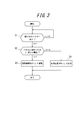
- FIG. 4 is a flowchart illustrating an operation of the electronic device according to the first embodiment. It is a figure which shows the functional block of the electronic device which concerns on Embodiment 2.
- FIG. It is a figure which shows an example of the relationship of the effective frequency band of the 1st piezoelectric element which concerns on Embodiment 2, and a 2nd piezoelectric element. It is a figure which shows the mounting structure of the electronic device which concerns on Embodiment 2.
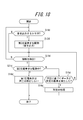
- FIG. 12 is a flowchart illustrating an example of an operation of the electronic device according to the second embodiment.
- FIG. 10 is a functional block diagram of an electronic device according to a fourth embodiment. It is a figure which shows an example of the mounting structure of the electronic device which concerns on Embodiment 4.
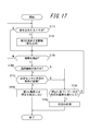
- FIG. 10 is a flowchart for explaining processing by the electronic apparatus according to the fourth embodiment.
- 14 is a flowchart for describing processing by the electronic apparatus according to the fifth embodiment.
- FIG. 10 is a functional block diagram of an electronic device according to a sixth embodiment. It is a figure which shows an example of the mounting structure of the electronic device which concerns on Embodiment 6.
- FIG. 14 is a flowchart for describing processing by the electronic apparatus according to the sixth embodiment.
- 15 is a flowchart for describing processing by the electronic apparatus according to the seventh embodiment.
- FIG. 10 is a functional block diagram of an electronic device according to an eighth embodiment. It is a figure which shows an example of the mounting structure of the electronic device which concerns on Embodiment 8.
- FIG. 16 is a flowchart for describing processing by the electronic apparatus according to the eighth embodiment.
- 14 is a flowchart for describing processing by the electronic apparatus according to the ninth embodiment.
- FIG. 16 is a functional block diagram of an electronic device according to an eleventh embodiment. It is a figure which shows an example of the mounting structure of the electronic device which concerns on Embodiment 11.
- FIG. 18 is a flowchart for describing processing by the electronic apparatus according to the eleventh embodiment. 18 is a flowchart for describing processing by the electronic apparatus according to the twelfth embodiment.
- FIG. 20 is a functional block diagram of an electronic device according to a thirteenth embodiment. It is a figure which shows an example of the mounting structure of the electronic device which concerns on Embodiment 13.
- FIG. 20 is a functional block diagram of an electronic device according to a thirteenth embodiment. It is a figure which shows an example of the mounting structure of the electronic device which concerns on Embodiment 13.
- 24 is a flowchart for describing processing by the electronic apparatus according to the thirteenth embodiment. 24 is a flowchart for describing processing by the electronic apparatus according to the fourteenth embodiment. It is a figure which shows an example of the vibration of the panel of the electronic device which concerns on this invention.
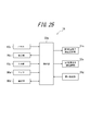
- FIG. 1 is a diagram showing functional blocks of an electronic device 1b according to an embodiment of the present invention.
- the electronic device 1b is, for example, a mobile phone (smart phone), and includes a panel 10, a display unit 20, a vibration unit 30, a detection unit 40, a control unit 50, and a communication unit 70.
- the vibration of the panel 10 generated by the vibration unit 30 generates a sound transmitted to the inside of the human body.
- the sound transmitted to the inside of the human body vibrates the middle ear or the inner ear via a soft tissue (for example, cartilage) of the human body.
- the panel 10 is a touch panel that detects contact, a cover panel that protects the display unit 20, or the like.
- the panel 10 is made of, for example, glass or a synthetic resin such as acrylic.
- the shape of the panel 10 may be a plate shape.
- the panel 10 may be a flat plate or a curved panel whose surface is smoothly inclined.
- a detection method of the touch panel any method such as a capacitance method, a resistance film method, a surface acoustic wave method (or an ultrasonic method), an infrared method, an electromagnetic induction method, and a load detection method can be used.
- the panel 10 is preferably rectangular.
- the display unit 20 is a display device such as a liquid crystal display, an organic EL display, or an inorganic EL display.
- the display unit 20 is provided on the back surface of the panel 10.
- the display unit 20 is disposed on the back surface of the panel 10 by a bonding member (for example, an adhesive).
- the display unit 20 may be disposed apart from the panel 10 and supported by the housing of the electronic device 1.
- the vibration unit 30 is an element that expands or contracts (bends) according to the electromechanical coupling coefficient of the constituent material by applying an electric signal (voltage).
- a piezoelectric element made of, for example, ceramic or quartz is used.
- the vibration unit 30 may be a unimorph, bimorph, or multilayer piezoelectric element.
- the stacked piezoelectric element includes a stacked unimorph element in which unimorphs are stacked (for example, 16 layers or 24 layers), or a stacked bimorph element in which bimorphs are stacked (for example, 16 layers or 24 layers are stacked).
- the laminated piezoelectric element is composed of a laminated structure of a plurality of dielectric layers made of, for example, PZT (lead zirconate titanate) and electrode layers arranged between the plurality of dielectric layers.
- a unimorph expands and contracts when an electric signal (voltage) is applied, and a bimorph bends when an electric signal (voltage) is applied.
- the vibration unit 30 is a piezoelectric element for transmitting sound.
- the vibration unit 30 is disposed on the back surface of the panel 10 by a joining member (for example, an adhesive).
- the detection unit 40 detects a pressure on the panel 10, for example, an element such as a strain gauge sensor or a piezoelectric element whose physical or electrical characteristics (strain, resistance, voltage, etc.) change according to the pressure. Use to configure.
- the piezoelectric element of the detection unit 40 has a magnitude (or load (force) of a load (force) related to pressing against the touch surface of the panel 10.
- the magnitude of the voltage (voltage value (hereinafter simply referred to as data)), which is an electrical characteristic, changes according to the speed (acceleration) at which the magnitude changes.
- the control unit 50 acquires the data when the detection unit 40 notifies the control unit 50 of the data, or when the control unit 50 detects data related to the piezoelectric element of the detection unit 40. That is, the control unit 50 acquires data based on the pressure on the touch surface of the panel 10 from the detection unit 40.
- the vibration unit 30 may be configured with a piezoelectric element and may also serve as the detection unit 40.
- the control unit 50 applies an electrical signal to the vibration unit 30, drives the vibration unit 30, and controls sound output.
- the voltage applied by the control unit 50 to the vibration unit 30 is, for example, ⁇ 15 V, which is higher than ⁇ 5 V, which is an applied voltage of a so-called panel speaker for the purpose of conducting sound by air conduction sound instead of vibration sound. It may be. Note that how much applied voltage is used can be appropriately adjusted according to the fixing strength of the panel 10 to the casing or the support member or the performance of the vibration unit 30.
- the control unit 50 drives the vibration unit 30 based on a sound output trigger from a predetermined application or the like (based on an audio signal or the like).
- control unit 50 changes the strength of vibration of the vibration unit 30 according to the force applied to the panel 10 detected by the detection unit 40. That is, when the force applied to panel 10 is equal to or greater than a predetermined threshold, control unit 50 increases the vibration of panel 10 more than when the force applied to panel 10 is less than the predetermined threshold. Specifically, the control unit 50 increases the voltage applied to the vibrating unit 30 when the force applied to the panel 10, that is, the data based on the pressure is greater than or equal to a predetermined threshold, than when the data is less than the predetermined threshold. For example, when the force applied to the panel 10 is equal to or greater than a predetermined threshold, the control unit 50 sets the vibration amplitude of the vibration unit 30 to A and vibrates the vibration unit 30.
- the control unit 50 sets the vibration amplitude of the vibration unit 30 to B (here, A> B) and vibrates the vibration unit 30.
- the predetermined threshold is 5N, or a data value (for example, 1V) based on a pressure detected (acquired) by the control unit 50 when 5N is added to the panel 10.
- the vibration unit 30 to which the electric signal is applied expands and contracts in the long side direction.
- the panel 10 to which the vibration unit 30 is attached is deformed according to the expansion and contraction of the vibration unit 30, and the panel 10 vibrates.
- the panel 10 is bent by the expansion / contraction or bending of the vibration unit 30.
- the panel 10 is bent directly by the vibration part 30.
- the panel 10 is bent directly by the vibration part means that the panel is specified by the inertial force of the piezoelectric actuator configured by arranging the vibration part in the casing as used in a conventional panel speaker. This is different from the phenomenon in which the panel is deformed by exciting the region.
- the panel 10 is directly bent by the vibrating part means that the expansion or contraction or bending (curving) of the vibrating part is that the panel is bent directly via the joining member or via the joining member and the reinforcing member described later. Means.
- the control unit 50 transmits the air conduction sound and the vibration sound to the object in contact with the panel 10.
- the control unit 50 can generate an air conduction sound and a vibration sound corresponding to the sound signal by applying an electric signal corresponding to the sound signal related to the voice of the other party to the vibration unit 30, for example.
- the audio signal may relate to a ringing melody or a music piece including music. Note that the audio signal applied to the electrical signal may be based on music data stored in the internal memory of the electronic device 1, or music data stored in an external server or the like is reproduced via a network. May be.
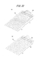
- the panel 10 vibrates not only in the attachment region to which the vibration unit 30 is attached, but also in the region away from the attachment region.
- the panel 10 has a plurality of locations that vibrate in a direction intersecting the main surface of the panel 10 in the vibrating region, and the amplitude value of the vibration is increased from positive to negative with time in each of the plurality of locations. Or vice versa.
- the panel 10 vibrates in such a manner that a portion having a relatively large vibration amplitude and a portion having a relatively small vibration amplitude are distributed randomly or periodically throughout the panel 10 at first glance. That is, vibrations of a plurality of waves are detected over the entire panel 10.
- the communication unit 70 is used to communicate with other electronic devices.
- the communication unit 70 allows the user of the electronic device 1 to make a call with a user such as another electronic device.
- a microphone (not shown) collects the voice spoken by the user of the electronic device 1. Further, the panel 10 vibrates and outputs a voice spoken by a user such as another electronic device.
- FIG. 2 is a diagram showing a mounting structure of electronic device 1 according to the present embodiment.
- the electronic device 1 shown in FIG. 2 is a smartphone in which a touch panel, which is a glass plate, is arranged as a panel 10 on the front surface of a housing 60 (for example, a metal or resin case).
- the panel 10 is supported by the housing 60, and the display unit 20 and the vibration unit 30 are bonded to the panel 10 with bonding members.
- the joining member is an adhesive having a thermosetting property or an ultraviolet curable property, a double-sided tape, or the like, and may be, for example, an optical elastic resin which is a colorless and transparent acrylic ultraviolet curable adhesive.
- the panel 10, the display unit 20, and the vibration unit 30 are each rectangular, but are not limited thereto.
- the display unit 20 is disposed approximately at the center of the panel 10 in the short direction.
- the vibration unit 30 is arranged at a predetermined distance from the end of the panel 10 in the longitudinal direction, and is arranged in the vicinity of the end so that the long side direction of the vibration unit 30 is along the short side of the panel 10.
- the display unit 20 and the vibration unit 30 are arranged side by side in a direction parallel to the inner surface of the panel 10.
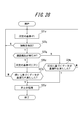
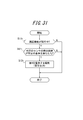
- control unit 50 detects whether there is a sound output trigger from a predetermined application or the like (step S1). If there is a sound output trigger, the process proceeds to step S2. If there is no sound output trigger, step S1 is repeated.
- control unit 50 determines whether the force applied to the panel 10 detected by the detection unit 40 is equal to or greater than a predetermined threshold (step S2). If it is equal to or greater than the predetermined threshold value, the process proceeds to step S3. If it is less than the predetermined threshold, the process proceeds to step S4.
- the control unit 50 sets the vibration amplitude of the vibration unit 30 to A and vibrates the vibration unit 30 (step S3). Then, the process ends.
- the control unit 50 sets the vibration amplitude of the vibration unit 30 to B and vibrates the vibration unit 30 (step S4). Then, the process ends.
- the vibration strength of the vibration unit 30 is changed according to the force applied to the panel 10. Sound can be transmitted effectively.
- the electronic device 1 can transmit air conduction sound and vibration sound transmitted through a part of the user's body (for example, cartilage of the outer ear) to the user by the vibration of the panel 10. Therefore, when outputting a sound having a volume equivalent to that of a conventional dynamic receiver, the sound transmitted to the periphery of the electronic device 1 due to the vibration of the air due to the vibration of the panel 10 is less than that of the dynamic receiver. Therefore, it is suitable, for example, when listening to a recorded message on a train or the like.
- the electronic device 1 transmits vibration sound due to the vibration of the panel 10, even if the user wears an earphone or a headphone, for example, the user can touch the electronic device 1 to contact the earphone or the headphone. Sounds can be heard through headphones and body parts.
- the electronic device 1 transmits sound to the user by the vibration of the panel 10. Therefore, when the electronic device 1 does not include a separate dynamic receiver, it is not necessary to form an opening (sound emission port) for sound transmission in the housing 60, and the waterproof structure of the electronic device 1 can be simplified.
- the sound emission port is preferably closed by a member that allows gas to pass but not liquid.
- a member that allows gas to pass but not liquid is Gore-Tex (registered trademark).
- the intensity of vibration corresponding to the force applied to the panel 10 is changed in two stages based on a predetermined threshold value.
- the present invention is not limited to this, and a plurality of threshold values may be provided to be multistage. . Further, the intensity of vibration may be continuously changed according to the force applied to the panel 10.
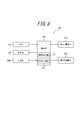
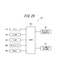
- FIG. 4 is a diagram showing functional blocks of the electronic device 1b according to Embodiment 2 of the present invention.
- the electronic device 1b is, for example, a mobile phone (smart phone), and includes a panel 10, a display unit 20, a first piezoelectric element 31b, a second piezoelectric element 32b, an input unit 40b, and a control unit 50b.
- the vibration of the panel 10 generated by the first piezoelectric element 32b and the second piezoelectric element 32b generates a sound transmitted to the inside of the human body.
- the sound transmitted to the inside of the human body vibrates the middle ear or the inner ear via a soft tissue (for example, cartilage) of the human body.
- the first piezoelectric element 31b is an element that expands or contracts (bends) according to the electromechanical coupling coefficient of the constituent material by applying an electric signal (voltage).
- the first piezoelectric element 31b may be a unimorph, bimorph, or multilayer piezoelectric element.
- the stacked piezoelectric element includes a stacked unimorph element in which unimorphs are stacked (for example, 16 layers or 24 layers), or a stacked bimorph element in which bimorphs are stacked (for example, 16 layers or 24 layers are stacked).
- the laminated piezoelectric element is composed of a laminated structure of a plurality of dielectric layers made of, for example, PZT (lead zirconate titanate) and electrode layers arranged between the plurality of dielectric layers.
- a unimorph expands and contracts when an electric signal (voltage) is applied, and a bimorph bends when an electric signal (voltage) is applied.
- the first piezoelectric element 31 b is a piezoelectric element for presenting a tactile sensation to a contact object in contact with the panel 10.
- the first piezoelectric element 31b is preferably rectangular and expands and contracts in the direction of the long side.
- the first piezoelectric element 31b is disposed on the back surface of the panel 10 by a bonding member (for example, an adhesive).
- the second piezoelectric element 32b is an element that expands or contracts (bends) according to the electromechanical coupling coefficient of the constituent material by applying an electric signal (voltage).
- the second piezoelectric element 32b may be a unimorph, bimorph, or multilayer piezoelectric element.
- the stacked piezoelectric element includes a stacked unimorph element in which unimorphs are stacked (for example, 16 layers or 24 layers), or a stacked bimorph element in which bimorphs are stacked (for example, 16 layers or 24 layers are stacked).
- the laminated piezoelectric element is composed of a laminated structure of a plurality of dielectric layers made of, for example, PZT (lead zirconate titanate) and electrode layers arranged between the plurality of dielectric layers.
- a unimorph expands and contracts when an electric signal (voltage) is applied, and a bimorph bends when an electric signal (voltage) is applied.
- the second piezoelectric element 32b is a piezoelectric element for transmitting sound.
- the second piezoelectric element 32b is preferably rectangular and expands and contracts in the direction of the long side.
- the second piezoelectric element 32b is disposed on the back surface of the panel 10 by a bonding member (for example, an adhesive).
- the input unit 40b detects an operation input by the user, and includes, for example, an operation button (operation key).
- an operation button operation key
- the panel 10 can also detect an operation by the user by detecting a contact by the user.
- the control unit 50b is a processor that controls the electronic device 1b.
- the controller 50b applies a predetermined electrical signal to the first piezoelectric element 31b and the second piezoelectric element 32b.
- the controller 50b applies an electrical signal to the first piezoelectric element 31b to drive the first piezoelectric element 31b.
- the electronic device 1b may include a pressure detection unit (not shown) that detects a pressure on the panel 10. Good. And if the data based on the press with respect to the panel 10 satisfy
- the pressure detection unit detects the pressure on the panel 10 and, for example, an element such as a strain gauge sensor or a piezoelectric element whose physical or electrical characteristics (strain, resistance, voltage, etc.) change according to the pressure, etc. To configure.
- the piezoelectric element of the pressure detection unit has a load (force) magnitude (or load (force)) related to the pressure on the touch surface of the panel 10.
- the magnitude of the voltage (voltage value (hereinafter simply referred to as data)), which is an electrical characteristic, changes according to the speed (acceleration) at which the magnitude changes.
- the control unit 50b acquires the data when the press detection unit notifies the control unit 50b of the data, or when the control unit 50b detects data related to the piezoelectric element of the press detection unit. That is, the control unit 50b acquires data based on the pressure on the touch surface of the panel 10 from the pressure detection unit.
- the press detection unit is configured by a piezoelectric element
- the first piezoelectric element 31b may also serve as the press detection unit.
- the controller 50b applies an electrical signal to the second piezoelectric element 32b, drives the second piezoelectric element 32b, and controls sound output.
- the voltage applied to the second piezoelectric element 32b by the control unit 50b is higher than ⁇ 5V, which is an applied voltage of a so-called panel speaker for the purpose of conducting sound by air conduction sound instead of vibration sound, for example, ⁇ It may be 15V.
- ⁇ 5V is an applied voltage of a so-called panel speaker for the purpose of conducting sound by air conduction sound instead of vibration sound, for example, ⁇ It may be 15V.
- the control unit 50b drives the second piezoelectric element 32b based on a sound output trigger from a predetermined application or the like (based on an audio signal (sound signal) or the like).
- the controller 50b controls to drive the first piezoelectric element 31b in addition to the second piezoelectric element 32b when outputting sound.
- the control unit 50b includes a signal combiner 51 (combiner).
- the signal combiner 51 combines the control signal related to the tactile sensation and the control signal related to the sound output, and supplies the combined signal to the first piezoelectric element 31b.
- the signal combiner 51 of the control unit 50b combines the control signal related to the tactile sensation and the control signal related to the sound output, the tactile sensation presenting function of the first piezoelectric element 31b is not disturbed.
- the first piezoelectric element 31b is a piezoelectric element for presenting a tactile sensation to the contact object in contact with the panel 10 as described above.
- the piezoelectric element for presenting a tactile sensation is larger in size than the piezoelectric element for transmitting sound. That is, preferably, the first piezoelectric element 31b is larger than the second piezoelectric element 32b, so that the resonance frequency of the first piezoelectric element 31b is lower than the resonance frequency of the second piezoelectric element 32b.
- the first piezoelectric element 31b transmits a low sound and the second piezoelectric element 32b transmits a high sound.
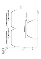
- FIG. 5 is a diagram showing a relationship between effective frequency bands of the first piezoelectric element 31b and the second piezoelectric element 32b in the second embodiment.
- the effective frequency band of the piezoelectric element is a frequency band in which the piezoelectric element can emit an audibly effective sound.
- the effective frequency band of the piezoelectric element is a frequency band having an amplitude that is 1/2 or more of the maximum amplitude with reference to the amplitude (maximum amplitude) at the resonance frequency of the piezoelectric element.
- FIG. 5B is a conceptual diagram relating to the resonance frequency and effective frequency band of a certain piezoelectric element. In FIG. 5B, the resonance frequency is Fx, and the effective frequency band is Fy to Fz.
- the amplitude at Fx is Ax.
- the amplitude at a certain frequency Fy (Fy ⁇ Fx) is Ay
- the amplitude at a certain frequency Fz (Fx ⁇ Fz) is Az.
- Ay and Az are 1/2 of Ax
- the amplitudes in Fy to Fz are 1/2 or more of Ax.
- the effective frequency band may be a frequency band having an amplitude of 1/3 or more of the maximum amplitude, and can be appropriately set depending on the product to be used. Further, the effective frequency band may be a 3 dB bandwidth centered on the resonance frequency.
- the resonance frequency and effective frequency band of the piezoelectric element may be those in a vibration system in which the piezoelectric element is mounted on the touch panel.
- the effective frequency band of the first piezoelectric element 31b and the effective frequency band of the second piezoelectric element 32b do not overlap.
- the effective frequency band of the first piezoelectric element 31b is 1 Hz or more and less than 400 Hz
- the effective frequency band of the second piezoelectric element 32b is 400 Hz or more and less than 20000 Hz.
- the controller 50b outputs sound
- the sound included in the effective frequency band of the first piezoelectric element 31b is output by the first piezoelectric element 31b and included in the effective frequency band of the second piezoelectric element 32b.
- the 1st piezoelectric element 31b and the 2nd piezoelectric element 32b complement each other.
- the control unit 50b applies an electrical signal to the first piezoelectric element 31b and the second piezoelectric element 32b
- the first piezoelectric element 31b and the second piezoelectric element 32b to which the electrical signal is applied expands and contracts in the long side direction.
- the panel 10 to which the first piezoelectric element 31b and the second piezoelectric element 32b are attached is deformed according to the expansion and contraction of the first piezoelectric element 31b and the second piezoelectric element 32b, and the panel 10 vibrates.
- the panel 10 is bent by expansion / contraction or bending of the first piezoelectric element 31b and the second piezoelectric element 32b.
- the panel 10 is bent directly by the first piezoelectric element 31b and the second piezoelectric element 32b.
- the panel 10 is directly bent by a piezoelectric element means that the panel is specified by the inertial force of a piezoelectric actuator configured by arranging a vibration part in a casing, as used in a conventional panel speaker. This is different from the phenomenon in which the panel is deformed by exciting the region.
- the panel 10 is directly bent by the piezoelectric element means that the expansion and contraction or bending (curving) of the piezoelectric element bends the panel directly via the bonding member or via the bonding member and the reinforcing member described later. Means.
- the control unit 50b transmits the air conduction sound and the vibration sound to the object in contact with the panel 10.
- the control unit 50b can apply an electrical signal corresponding to a voice signal related to the voice of the other party to the second piezoelectric element 32b, for example, and generate air conduction sound and vibration sound corresponding to the voice signal.
- the audio signal may relate to a ringing melody or a music piece including music.
- the audio signal applied to the electrical signal may be based on music data stored in the internal memory of the electronic device 1b, or music data stored in an external server or the like may be reproduced via a network. May be.
- the panel 10 vibrates not only in the attachment region where the first piezoelectric element 31b and the second piezoelectric element 32b are attached, but also in the region away from the attachment region.
- the panel 10 has a plurality of locations that vibrate in a direction intersecting the main surface of the panel 10 in the vibrating region, and the amplitude value of the vibration is increased from positive to negative with time in each of the plurality of locations. Or vice versa.
- the panel 10 vibrates in such a manner that a portion having a relatively large vibration amplitude and a portion having a relatively small vibration amplitude are distributed randomly or periodically throughout the panel 10 at first glance. That is, vibrations of a plurality of waves are detected over the entire panel 10.
- the control unit 50b applies the second piezoelectric element 32b to prevent the above-described vibration of the panel 10 from being attenuated.
- the applied voltage may be ⁇ 15V. Therefore, the user can hear the sound by bringing his / her ear into contact with a region away from the above-described region where the panel 10 is attached.
- FIG. 6 is a diagram showing a mounting structure of electronic device 2b according to the present embodiment.
- An electronic device 1b illustrated in FIG. 6 is a smartphone in which a touch panel, which is a glass plate, is arranged as a panel 10 on the front surface of a housing 60 (for example, a metal or resin case).
- the panel 10 and the input unit 40b are supported by the housing 60, and the display unit 20, the first piezoelectric element 31b, and the second piezoelectric element 32b are bonded to the panel 10 with bonding members, respectively.
- the joining member is an adhesive having a thermosetting property or an ultraviolet curable property, a double-sided tape, or the like, and may be, for example, an optical elastic resin which is a colorless and transparent acrylic ultraviolet curable adhesive.
- the panel 10, the display unit 20, the first piezoelectric element 31b, and the second piezoelectric element 32b are each rectangular.
- the display unit 20 is disposed approximately at the center of the panel 10 in the short direction.
- the first piezoelectric element 31b is separated from the end in the longitudinal direction of the panel 10 by a predetermined distance, and the long side direction of the first piezoelectric element 31b is along the short side of the panel 10 in the vicinity of the end. Be placed.
- the display unit 20 and the first piezoelectric element 31 b are arranged side by side in a direction parallel to the inner surface of the panel 10.
- the second piezoelectric element 32b is separated from the end in the longitudinal direction of the panel 10 by a predetermined distance, and the long side direction of the second piezoelectric element 32b is along the short side of the panel 10 in the vicinity of the end.
- the position where the first piezoelectric element 31b and the second piezoelectric element 32b are arranged is an example, and is not limited thereto.
- the long side direction of the second piezoelectric element 32 b may be arranged along the long side of the panel 10.
- the 2nd piezoelectric element 32b may be arrange
- the first piezoelectric element 31b and the second piezoelectric element 32b are preferable because they do not act in the direction of preventing vibration from each other.
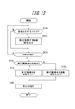
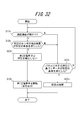
- control unit 50b detects whether or not there is a trigger for sound output from a predetermined application or the like (step S11). If there is a sound output trigger, the process proceeds to step S12. If there is no sound output trigger, step S11 is repeated.
- step S12 When there is a sound output trigger, when the controller 50b outputs a sound, the sound included in the effective frequency band of the first piezoelectric element 31b is output by the first piezoelectric element 31b, and the second piezoelectric element 32b The sound included in the effective frequency band is output by the second piezoelectric element 32b (step S12). Then, the process ends.
- the electronic apparatus 1b when outputting sound, the sound included in the effective frequency band of the first piezoelectric element 31b is output by the first piezoelectric element 31b, and the second piezoelectric element 31b is output.
- the sound included in the effective frequency band of the element 32b is output by the second piezoelectric element 32b. Therefore, when the piezoelectric element for the tactile sensation presentation function and the piezoelectric element for the conduction function such as the air conduction sound are disposed, the first piezoelectric element 31b and the second piezoelectric element 32b compensate for the effective frequency band, and the sound Is output, so that the acoustic effect can be improved.
- the electronic device 1b described above can transmit air conduction sound and vibration sound transmitted through a part of the user's body (for example, cartilage of the outer ear) to the user by the vibration of the panel 10. Therefore, when outputting a sound having a volume equivalent to that of a conventional dynamic receiver, the sound transmitted to the surroundings of the electronic device 1b due to the vibration of air due to the vibration of the panel 10 is less than that of the dynamic receiver. Therefore, it is suitable, for example, when listening to a recorded message on a train or the like.
- the electronic device 1b transmits vibration sound by the vibration of the panel 10, even if the user wears an earphone or a headphone, for example, by bringing the electronic device 1b into contact with the user, Sounds can be heard through headphones and body parts.
- the electronic device 1b transmits sound to the user by the vibration of the panel 10. Therefore, when the electronic device 1b does not include a separate dynamic receiver, it is not necessary to form an opening (sound outlet) for sound transmission in the housing 60, and the waterproof structure of the electronic device 1b can be simplified.
- the sound emission port is preferably closed by a member that allows gas to pass but not liquid.
- a member that allows gas to pass but not liquid is Gore-Tex (registered trademark).
- the third embodiment of the present invention will be described below.
- symbol is attached
- the electronic device 2b of the second embodiment is different from the electronic device 1b of the first embodiment in that the relationship between the effective frequency bands of the first piezoelectric element 31b and the second piezoelectric element 32b is different. Specifically, the effective frequency band of the first piezoelectric element 31b and the effective frequency band of the second piezoelectric element 32b are different.
- FIG. 8 is a diagram showing functional blocks of the electronic device 2b according to Embodiment 3 of the present invention.
- the electronic device 2b according to the second embodiment is different from the electronic device 1b according to the first embodiment in that the control unit 50b includes a band separator 52 in addition to the configuration of the electronic device 1b according to the first embodiment.
- the band separator 52 separates the frequency band so that the combined frequency characteristics are flat. Specifically, the volume of the frequency region where the effective frequency band of the first piezoelectric element 31b and the effective frequency band of the second piezoelectric element 32b overlap is extremely large compared to the volume of other frequency regions. Accordingly, the band separator 52 separates the signal related to the output sound based on the frequency band so that the volume of the overlapping frequency region does not deviate too much from the volume of the non-overlapping portion, and the first and second piezoelectric elements 31b and 2 The separated signal is passed to the piezoelectric element 32b.
- the band separator 52 does not separate the signal related to the sound to be output, and the volume in the frequency region where the effective frequency band of the first piezoelectric element 31b and the effective frequency band of the second piezoelectric element 32b overlap. That is, it is effective to make the bass sound louder than the sound volume in other frequency regions.
- FIG. 9 is a diagram showing a relationship between effective frequency bands of the first piezoelectric element 31b and the second piezoelectric element 32b according to the second embodiment.
- the effective frequency band of the first piezoelectric element 31b and the effective frequency band of the second piezoelectric element 32b overlap.
- the effective frequency band of the first piezoelectric element 31b is 1 Hz or more and less than 400 Hz
- the effective frequency band of the second piezoelectric element 32b is 200 Hz or more and less than 20000 Hz.
- the control unit 50b controls to drive the first piezoelectric element 31b in addition to the second piezoelectric element 32b.
- the control unit 50b drives the second piezoelectric element 32b without driving the first piezoelectric element 31b.
- Whether the bass is emphasized is determined by the input unit 40b detecting an operation input by the user.
- the input unit 40b makes a setting for emphasizing bass (hereinafter referred to as bass emphasis setting) or cancels the bass emphasis setting based on an operation input by the user.
- step S11 determines whether or not the electronic apparatus 2b is set to emphasize bass (step S22). If the bass enhancement setting is selected, the process proceeds to step S23. If it is not the bass enhancement setting, the process proceeds to step S24.
- control unit 50b controls the sound to be output so as to drive the first piezoelectric element 31b in addition to the second piezoelectric element 32b (step S23). Then, the process ends.
- controller 50b drives the second piezoelectric element 32b without driving the first piezoelectric element 31b when not emphasizing the bass (step S24). Then, the process ends.
- the electronic device 2b when emphasizing the bass sound, in addition to the second piezoelectric element 32b, control is performed so as to drive the first piezoelectric element 31b.
- the acoustic effect can be improved.
- the bass emphasis setting is switched depending on whether the first piezoelectric element 31b and the second piezoelectric element 32b are used or only the second piezoelectric element 32b is used.
- the present invention is not limited to this.
- the intensity of vibration of the first piezoelectric element 31b may be changed in addition to the second piezoelectric element 32b in accordance with the degree of bass emphasis.
- the band separated by the band separator 52 may be changed according to the degree of bass emphasis.
- Embodiment 4 an embodiment of an electronic apparatus according to Embodiment 4 of the present invention will be described with reference to the drawings.
- symbol is attached
- the electronic device according to the present invention can be a mobile phone, a smartphone, a tablet PC, or the like provided with a touch panel.
- the present invention is not limited to these portable devices, and can be various electronic devices such as home appliances, industrial devices (FA devices), and dedicated terminals provided with a touch panel.
- FA devices industrial devices
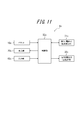
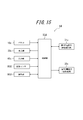
- FIG. 11 is a functional block diagram of an electronic device according to Embodiment 4 of the present invention.
- an electronic apparatus 1c according to Embodiment 4 of the present invention includes a panel 10c, a display unit 20c, a first piezoelectric element 31c, a second piezoelectric element 32c, an input unit 40c, and a control unit 50c. Yes.
- the vibration of the panel 10c generated by the second piezoelectric element 32c generates a sound transmitted to the inside of the human body.
- the sound transmitted to the inside of the human body vibrates the middle ear or the inner ear via a soft tissue (for example, cartilage) of the human body.
- the panel 10c can be a touch panel for detecting contact, a cover panel for protecting the display unit 20c, or the like.
- the panel 10c is preferably formed of a synthetic resin such as glass or acrylic.
- the panel 10c is formed of a synthetic resin such as glass or acrylic.
- the shape of the panel 10c may be a plate shape.
- the panel 10c may be a flat plate, or may be a curved panel whose surface is smoothly inclined. When the panel 10c is a touch panel, it detects contact of a user's finger or stylus pen.
- the detection method of the touch panel should be an arbitrary method such as a capacitance method, a resistance film method, an optical method, a surface acoustic wave method (or an ultrasonic method), an infrared method, an electromagnetic induction method, and a load detection method. Can do.
- the panel 10c is arranged in a housing or the like so as to be able to vibrate by an appropriate means. That is, if all the edges of the panel 10c are firmly fixed to the housing or the like, the amplitude when the panel 10c is vibrated cannot be obtained, and a good tactile sensation cannot be presented to the user. Therefore, for example, the panel 10c is disposed in the housing via an elastic member, or the panel 10c is partially fixed to the housing, so that the panel 10c can be vibrated and disposed in the housing. It is preferable to install them.
- the panel 10c When the panel 10c is configured by a member such as a touch panel, the panel 10c detects contact with a touch surface such as a user's finger or stylus pen, and outputs information on the position of the contact. With this output, the control unit 50c can acquire the position of the contact detected by the panel 10c.
- the display unit 20c is a display device such as a liquid crystal display, an organic EL display, or an inorganic EL display.
- the display unit 20c can display various information, images, and objects such as keys and buttons on the screen.
- the display unit 20c is provided on the back surface of the panel 10c.
- the display part 20c is arrange
- the display unit 20c may be disposed apart from the panel 10c and supported by the casing of the electronic device 1c.
- the panel 10c is configured with a member such as a touch panel, it is preferable that the panel 10c is configured with, for example, a transparent member and the display unit 20c is disposed on the back side thereof.
- an object such as a key or a button can be drawn and displayed on the display unit 20c, and an operation of the user pressing the object can be detected on the panel 10c.
- Such display of the display unit 20c can be performed by control by the control unit 50c.
- the first piezoelectric element 31c and the second piezoelectric element 32c are elements that expand or contract (bend) according to the electromechanical coupling coefficient of the constituent material by applying an electric signal (voltage). These piezoelectric elements are made of, for example, ceramic or quartz.
- the first piezoelectric element 31c and the second piezoelectric element 32c can be unimorphs, bimorphs, or stacked piezoelectric elements.
- the stacked piezoelectric element includes a stacked unimorph element in which unimorphs are stacked (for example, 16 layers or 24 layers), or a stacked bimorph element in which bimorphs are stacked (for example, 16 layers or 24 layers are stacked).
- the laminated piezoelectric element is composed of a laminated structure of a plurality of dielectric layers made of, for example, PZT (lead zirconate titanate) and electrode layers arranged between the plurality of dielectric layers.
- PZT lead zirconate titanate
- a unimorph expands and contracts when an electric signal (voltage) is applied, and a bimorph bends when an electric signal (voltage) is applied.
- the first piezoelectric element 31c and the second piezoelectric element 32c are preferably arranged on the back surface of the panel 10c (the surface on the inner side of the electronic device 1c).
- the first piezoelectric element 31c and the second piezoelectric element 32c are attached to the panel 10c by a joining member (for example, double-sided tape).
- the first piezoelectric element 31c and the second piezoelectric element 32c may be attached to the panel 10c via an intermediate member (for example, a sheet metal).
- the first piezoelectric element 31c and the second piezoelectric element 32c are arranged on the back surface of the panel 10c and are separated from the inner surface of the housing by a predetermined distance.
- the first piezoelectric element 31c and the second piezoelectric element 32c be separated from the surface on the inner side of the housing by a predetermined distance even in a stretched or bent state. That is, the distance between the first piezoelectric element 31c and the second piezoelectric element 32c and the inner surface of the housing is set to be larger than the maximum deformation amount of the first piezoelectric element 31c and the second piezoelectric element 32c. Is preferred.
- the first piezoelectric element 31c is a piezoelectric element mainly used for presenting a tactile sensation. Therefore, it is desirable that the first piezoelectric element 31c be designed so as to have a frequency characteristic suitable for presenting a predetermined tactile sensation based on an electrical signal from the control unit 50c.
- the second piezoelectric element 32c is a piezoelectric element mainly used for transmitting sound. Therefore, it is desirable to employ the second piezoelectric element 32c designed to have a frequency characteristic suitable for transmitting a predetermined sound based on the electric signal from the control unit 50c.
- the first piezoelectric element and the second piezoelectric element are disposed on the panel 10c as different piezoelectric elements.
- the input unit 40c detects a user's input operation and includes, for example, operation buttons (operation keys).
- the user input operation detected by the input unit 40c is sent to the control unit 50c as an electrical signal.
- the panel 10c is a touch panel, the panel 10c can also detect the contact from a user.
- the control unit 50c is a processor that controls the electronic device 1c.
- the controller 50c applies a predetermined electrical signal to the first piezoelectric element 31c and the second piezoelectric element 32c.
- the control unit 50c applies an electrical signal to the first piezoelectric element 31c to drive the first piezoelectric element 31c.
- the controller 50c applies an electrical signal to the second piezoelectric element 32c, drives the second piezoelectric element 32c, and controls sound output.
- the control unit 50c is based on a sound output trigger from a predetermined application or the like (based on a sound signal (sound signal) or the like). It can be controlled to drive the second piezoelectric element 32c.
- the voltage applied to the second piezoelectric element 32c by the control unit 50c is higher than ⁇ 5 V, which is an applied voltage of a so-called panel speaker for the purpose of conducting sound by air conduction sound instead of vibration sound, for example. , ⁇ 15V.
- ⁇ 5 V is an applied voltage of a so-called panel speaker for the purpose of conducting sound by air conduction sound instead of vibration sound, for example. , ⁇ 15V.
- the controller 50c applies an electrical signal to the first piezoelectric element 31c and the second piezoelectric element 32c
- the first piezoelectric element 31c and the second piezoelectric element 32c to which the electrical signal is applied expands and contracts in the long side direction of each element.
- the panel 10c to which the first piezoelectric element 31c and the second piezoelectric element 32c are attached is deformed according to the expansion and contraction of the first piezoelectric element 31c and the second piezoelectric element 32c, and the panel 10c vibrates.
- the panel 10c is curved by expansion / contraction or bending of the first piezoelectric element 31c and the second piezoelectric element 32c.
- the panel 10c is bent directly by the first piezoelectric element 31c and the second piezoelectric element 32c.
- the panel 10c is directly bent by the piezoelectric element means that the panel is specified by the inertial force of the piezoelectric actuator configured by arranging the piezoelectric element in the casing as used in a conventional panel speaker. This is different from the phenomenon in which the panel is deformed by exciting the region.
- the panel 10c is directly bent by the piezoelectric element means that the expansion or contraction (bending) of the piezoelectric element bends the panel directly via the bonding member or via the bonding member and the reinforcing member described later. Means.
- the panel 10c When the second piezoelectric element 32c expands and contracts and the panel 10c vibrates, the panel 10c generates air conduction sound, and when the user touches a part of the body (for example, cartilage of the outer ear), A vibration sound transmitted through a part is generated. Then, the control unit 50c transmits the air conduction sound and the vibration sound to the object in contact with the panel 10c.
- the control unit 50c can apply an electric signal corresponding to a voice signal related to the voice of the other party to the second piezoelectric element 32c, for example, and generate air conduction sound and vibration sound corresponding to the voice signal.
- the audio signal may relate to a ringing melody or a music piece including music. Note that the audio signal applied to the electrical signal may be based on music data stored in the internal memory of the electronic device 1c, or music data stored in an external server or the like is reproduced via a network. May be.
- the panel 10c vibrates not only in the attachment region where the second piezoelectric element 32c is attached, but also in the region away from the attachment region.
- the panel 10c has a plurality of locations that vibrate in a direction intersecting with the main surface of the panel 10c in a region where the vibration is generated, and the amplitude value of the vibration at each of the plurality of locations increases from plus to minus with time. And vice versa.
- the panel 10c vibrates in such a manner that a portion having a relatively large vibration amplitude and a portion having a relatively small vibration amplitude are distributed randomly or periodically over the entire panel 10c. That is, vibrations of a plurality of waves are detected over the entire area of the panel 10c.
- the control unit 50c applies the second piezoelectric element 32c to suppress the above-described vibration attenuation of the panel 10c.
- the applied voltage may be ⁇ 15V. Therefore, the user can listen to the sound by bringing his / her ear into contact with an area away from the above-described attachment area of the panel 10c.
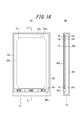
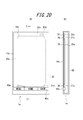
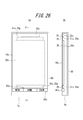
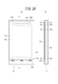
- FIG. 12 is a diagram illustrating an example of a mounting structure of the electronic device 1c according to the first embodiment. 12A is a front view, and FIG. 2B is a cross-sectional view taken along the line CC in FIG. 2A.
- the electronic device 1c shown in FIG. 12 is a smartphone in which a touch panel that is a glass plate is arranged on the front surface of a housing 60 (for example, a metal or resin case) as the panel 10c.
- the panel 10c and the input unit 40c are supported by the housing 60.
- the display unit 20c, the first piezoelectric element 31c, and the second piezoelectric element 32c are bonded to the panel 10c via the bonding member 70, respectively.
- the first piezoelectric element 31c and the second piezoelectric element 32c are bonded to the back side of the panel. In order to show this, in FIG.
- the joining member 70 is an adhesive having a thermosetting property or an ultraviolet curable property, a double-sided tape, or the like, and may be, for example, an optical elastic resin that is a colorless and transparent acrylic ultraviolet curable adhesive.
- the panel 10c, the display unit 20c, the first piezoelectric element 31c, and the second piezoelectric element 32c are each substantially rectangular.
- the display unit 20c is disposed substantially at the center in the short direction of the panel 10c. Further, the first piezoelectric element 31c and the second piezoelectric element 32c are separated from the end in the longitudinal direction of the panel 10c by a predetermined distance, and in the vicinity of the end, the first piezoelectric element 31c and the second piezoelectric element 32c. Are arranged such that the longitudinal direction of the panel extends along the short side of the panel 10c.
- the display unit 20c, the first piezoelectric element 31c, and the second piezoelectric element 32c are arranged side by side in a direction parallel to the surface on the back side of the panel 10c.
- the arrangement is not limited to the illustrated example.
- at least one of the first piezoelectric element 31c and the second piezoelectric element 32c can be arranged in parallel to the longitudinal direction of the electronic apparatus 1c (the longitudinal direction in FIG. 12A).
- the first piezoelectric element 31c and the second piezoelectric element 32c can be arbitrarily configured so as to be able to transmit vibration to the panel 10c by being attached to the panel 10c.
- the display unit 20 c is configured to be bonded to the back side of the panel 10 c via the bonding member 70, but the arrangement of the display unit 20 c is not limited to the illustrated example.
- the display unit 20c can be adhered to the back surface side of the panel 10c without the joining member 70, or can be disposed inside the housing 60 instead of being adhered to the panel 10c.
- the display unit 20 c is arranged inside the housing 60, the display unit 20 c is arranged and fixed directly inside the housing 60, or for a substrate or display unit arranged inside the housing 60. It can be fixed to a holder or the like. As shown in FIG.
- the electronic device 1c can include, for example, the control unit 50c and various elements such as various boards or components other than those shown in FIG.
- an area on the panel 10c where the display by the display unit 20c does not need to be transmitted is an area near the edge of the panel 10c. It is preferred to paint or cover with a bezel. In this way, it is possible to prevent the first piezoelectric element 31c, the second piezoelectric element 32c, and the like from being visible from the outside of the electronic device 1c.
- the control unit 50c performs control so as to output sound by driving the second piezoelectric element 32c.
- the 2nd piezoelectric element can implement
- the control unit 50c controls the first piezoelectric element 31c to be driven when the panel 10c detects contact.
- the 1st piezoelectric element can implement
- the piezoelectric element for presenting tactile sensation is driven when the sound transmitting piezoelectric element is vibrated to output sound. If vibration is generated, there is a risk of interference due to vibration of both piezoelectric elements. Therefore, in the present embodiment, processing as described below is performed under the control of the control unit 50c.
- FIG. 13 is a flowchart for explaining processing by the control unit 50c of the electronic device 1c according to the fourth embodiment.
- the control unit 50c determines whether or not a trigger for outputting a sound has occurred (step S11c).
- the trigger for outputting a sound is assumed to be various instructions such as an instruction to sound a ring tone by a call application when a call is received, or an instruction to play music by a music player application, for example. can do.
- the trigger for outputting sound is an arbitrary instruction that causes the panel 10c to vibrate and output sound by driving the second piezoelectric element 32c for sound output in the electronic device 1c. be able to.
- control unit 50c controls to output sound by driving the second piezoelectric element 32c (step S12c).
- step S12c the control unit 50c determines whether or not the panel 10c detects contact with a user's finger or ear (step S13c). In addition, when the trigger which outputs a sound has not generate
- step S13c When the panel 10c does not detect contact in step S13c, the control unit 50c returns to step S11c and continues the process. On the other hand, when the panel 10c detects contact in Step S13c, the control unit 50c determines whether or not the second piezoelectric element is being driven (Step S14c).
- step S14c If it is determined in step S14c that the second piezoelectric element is not being driven, there is no problem of interference even if vibration for presenting a tactile sensation is generated at this point, and therefore the control unit 50c causes the first piezoelectric element 31c to move. It controls to drive and to show a tactile sensation (step S15c). That is, when the panel 10c is touched in step S13c and no sound is output in step S14c, a tactile sensation is presented based on the touch. Therefore, the user can confirm by tactile sensation that the user's operation touching the panel 10c is correctly detected by the electronic device 1c.
- the control unit 50c performs control based on the position of the contact detected in step S13c so as to perform a predetermined process associated with the position.
- the predetermined processing is, for example, when the position of the contact detected on the panel 10c in step S13c corresponds to the position where the icon for starting the phone book application is displayed on the display unit 20c. It can be set as the process which starts.
- the predetermined process refers to the case where the position of the contact detected on the panel 10c in step S13c corresponds to the position where the character key is displayed on the display unit 20c, and the character key is displayed on the display unit 20c. The process can be displayed.
- the control unit 50c performs the present processing without performing predetermined processing in step S16c. It is preferable to end the processing of the embodiment.
- the case where no processing is associated with the detected contact position means, for example, that the contact position detected in the panel 10c in step S13c is an object such as any icon or key on the display unit 20c. The case where it corresponds to the position which is not displayed also can be assumed.
- step S14c determines whether the second piezoelectric element is being driven (the control unit 50c is driving the second piezoelectric element)
- the control unit 50c performs control so as not to drive the first piezoelectric element 31c (step S17c). That is, when the panel 10c is touched in step S13c and sound is output in step S14c, the tactile sensation based on the touch is not presented. Therefore, in this embodiment, when the second piezoelectric element is being driven and the sound is being output, the first piezoelectric element that presents a tactile sensation is driven, thereby causing interference due to vibrations of both piezoelectric elements. None do.
- the control unit 50c preferably performs control so as to perform a predetermined process corresponding to the position based on the position of contact detected in step S13c without presenting the tactile sensation. Yes (step S16c).
- the control unit 50c controls to output sound by driving the second piezoelectric element 32c, and drives the first piezoelectric element 31c based on the contact with the panel 10c and is predetermined. Control to perform the process.
- the control unit 50c while the second piezoelectric element 32c is being driven, the control unit 50c performs the predetermined process based on the contact with the panel 10c without driving the first piezoelectric element 31c.
- the electronic apparatus 1c when a plurality of the first piezoelectric elements 31c (two in the example of FIG. 12) are arranged as shown in FIG. 12, the second piezoelectric element 32c is all driven.
- the example in which the first piezoelectric element 31c is controlled not to be driven has been described.
- the electronic apparatus 1c according to the present embodiment can substantially prevent interference due to vibration of these piezoelectric elements even when a plurality of piezoelectric elements having different applications are arranged.
- the first piezoelectric element should be driven to present a tactile sensation even while the second piezoelectric element 32c is driven to output sound.
- control is performed so that a part of the plurality of first piezoelectric elements 31c is not driven.
- the control unit 50c is disposed closest to the second piezoelectric element 32c among the plurality of first piezoelectric elements 31c based on the contact with the panel 10c. It is preferable to perform control so as to perform a predetermined process without driving the first piezoelectric element 31c. For example, as shown in FIG. 12, when two upper and lower first piezoelectric elements 31c are provided, the second piezoelectric element 32c of the two first piezoelectric elements 31c is driven while the second piezoelectric element 32c is driven. It can be controlled not to drive the first upper piezoelectric element 31c on the upper side.
- step S13c when contact with the panel 10c is detected in step S13c, if no processing is associated with the detected contact position, the predetermined processing is not performed in step S16c. You can also
- the tactile sensation presentation piezoelectric element when a tactile sensation presentation piezoelectric element is driven and a tactile sensation is presented while a sound transmitting piezoelectric element is driven to generate sound, the tactile sensation presentation piezoelectric element also vibrates the panel. The vibration is superimposed as noise on the air conduction sound or vibration sound.
- a microphone is usually installed. For this reason, in such an electronic device, when a piezoelectric element is driven to generate a sound and a tactile sensation is presented by driving another piezoelectric element, the microphone uses the vibration associated with the tactile sensation as noise. Sound is collected.
- Embodiment 5 Next, an electronic apparatus according to Embodiment 5 of the present invention will be described.
- symbol is attached
- the electronic device 2c according to the fifth embodiment changes the control by the control unit 50c in the electronic device 1c according to the fourth embodiment. Therefore, Embodiment 5 of the present invention can be basically implemented by an electronic device having the same configuration as the electronic device 1c described in Embodiment 4. For this reason, the description which becomes the same as Embodiment 4 is abbreviate
- the first piezoelectric element 31c is not driven while driving the second piezoelectric element 32c after the user presses the panel 10c while the contact with the panel 10c is detected. Control to perform a predetermined process.
- the first piezoelectric element 31c attached to the panel 10c detects a pressure on the panel 10c.
- a piezoelectric element generates a voltage when pressure is applied, and deforms when a voltage is applied. Therefore, the first piezoelectric element 31c may serve as both a functional unit (tactile sensation providing unit) that presents a tactile sensation by generating vibration and a functional unit (press detection unit) that detects a pressure on the panel 10c. it can.
- Such a pressure detection unit detects a pressure on the touch surface of the panel 10c.
- a strain gauge sensor or a piezoelectric device whose physical or electrical characteristics (distortion, resistance, voltage, etc.) change according to the pressure.
- An arbitrary number of elements can be used.
- the piezoelectric element of the pressure detection unit changes the magnitude of the load (force) related to the pressure on the panel 10c (or the magnitude of the load (force)).
- the voltage magnitude (voltage value) which is an electrical characteristic, changes according to the speed (acceleration)).
- the pressure detection unit can notify the control unit 50c of the magnitude of the voltage (voltage value (hereinafter simply referred to as data)).
- the control unit 50c acquires the data when the press detection unit notifies the control unit 50c of the data, or when the control unit 50c detects data related to the piezoelectric element of the press detection unit.
- the control unit 50c acquires data based on the pressure on the panel 10c. That is, the control unit 50c acquires data based on the pressure from the pressure detection unit. Then, the control unit 50c can determine that an operation intended by the user has been performed when the data based on the pressure satisfies a predetermined standard, and can generate a predetermined vibration.
- the predetermined reference can be set as appropriate according to the load characteristic when the push button switch is to be expressed.
- the time when the data based on the pressure satisfies the predetermined standard may be the time when the voltage value (data) reaches the predetermined standard value, or the voltage value (data) exceeds the predetermined standard value. Or a voltage value (data) equal to a predetermined reference value may be detected.
- control unit 50c controls to output sound by driving the second piezoelectric element 32c.
- the second piezoelectric element is similar to the fourth embodiment in that it can realize a function of outputting sound and transmitting the sound to the user.
- the control unit 50c drives the first piezoelectric element 31c when the data based on the pressure detected by the first piezoelectric element 31c satisfies a predetermined reference while the panel 10c detects contact. Control is performed so as to perform predetermined processing as necessary.
- the 1st piezoelectric element can implement
- FIG. 14 is a flowchart for describing processing by the control unit 50c of the electronic apparatus 2c according to the fifth embodiment.
- the process performed by the control unit 50c in the fifth embodiment is to insert step S21c between step S13c and step S14c in the process according to the fourth embodiment described in FIG.
- the control unit 50c determines that the data based on the pressure on the panel 10c detected by the first piezoelectric element 31c (the pressure detection unit) is the predetermined value described above. It is determined whether or not the standard is satisfied (step S21c).
- step S14c determines whether or not the second piezoelectric element that outputs sound is being driven (step S14c). Step S14c and subsequent steps are the same as the processing according to the fourth embodiment described with reference to FIG. That is, while the second piezoelectric element 32c is being driven, the first piezoelectric element 31c is controlled not to be driven so that a predetermined process is performed. When the second piezoelectric element is not being driven, the first piezoelectric element 31c is driven to feel the touch. Control to perform a predetermined process after presenting.
- the control unit 50c performs predetermined processing without driving the first piezoelectric element 31c based on the pressure applied to the panel 10c while the second piezoelectric element 32c is being driven. Control to do. Therefore, the electronic apparatus 2c according to the present embodiment can substantially prevent interference due to vibration of these piezoelectric elements even when a plurality of piezoelectric elements having different uses are arranged.
- the first piezoelectric element is driven and presents a tactile sensation while the user presses the panel 10c to some extent, so that it is realistic as obtained when the mechanical key is actually pressed. A tactile sensation is presented.
- the predetermined process is not performed only when a light contact is detected on the panel 10c, and the predetermined process is performed when a press based on the user's intention is given. It is also possible to prevent a predetermined process from starting based on an operation that is not performed.
- step S16c when contact with the panel 10c is detected in step S13c, if no processing is associated with the detected contact position, step S16c is performed. It is also possible not to perform the predetermined processing in step. Also in the present embodiment, as described in the fourth embodiment, while the second piezoelectric element 32c is driven to output sound, a part of the plurality of first piezoelectric elements 31c is driven. By controlling so as not to cause the interference, the interference caused by these piezoelectric elements can be reduced.
- the configuration in which the first piezoelectric element 31c serves as both a tactile sensation providing unit and a press detection unit has been described.
- the first piezoelectric element 31c may be provided with a tactile sensation and may be provided with a pressure detection unit separate from the first piezoelectric element 31c.
- the control unit 50c proceeds to step S14c and performs processing. To continue.
- control is performed so that the first piezoelectric element does not present a tactile sensation while the second piezoelectric element outputs sound.
- the control unit 50c can also control the other piezoelectric element not to be driven while one of the second piezoelectric element 32c and the first piezoelectric element 31c is being driven.
- the control unit 50c can be controlled so as not to drive the second piezoelectric element 32c while the first piezoelectric element 31c is being driven.
- an aspect has been described in which an object is displayed on the display unit 20c disposed on the back side of the panel and the panel 10c detects a user's contact.
- the present invention is not limited to such an aspect, and can be applied to an aspect in which an object is directly printed on the panel 10c with ink or the like without the display unit 20c. .
- the panel 10c is used to detect contact with the panel 10c. That is, in the above embodiment, the panel 10c has been described assuming a member such as a so-called touch sensor.
- the touch panel used in the electronic device according to the present invention may be any as long as it can be touched by a contact object such as a user's finger or a stylus pen.
- the panel used in the electronic apparatus according to the present invention may be a member that does not detect the position of contact of the contact object with the panel (that is, does not have a sensing function).
- the electronic device having such a configuration for example, it is possible to determine that contact with the panel has been made based on the pressure detected by the pressure detection unit by further providing a pressure detection unit that detects pressure on the panel. it can.
- the electronic device 1c described above can transmit air conduction sound and vibration sound transmitted through a part of the user's body (for example, cartilage of the outer ear) to the user by vibration of the panel 10c. . Therefore, when outputting a sound having a volume equivalent to that of a conventional dynamic receiver, the sound transmitted to the surroundings of the electronic device 1c due to the vibration of air due to the vibration of the panel 10c is less than that of the dynamic receiver. Therefore, it is suitable, for example, when listening to a recorded message on a train or the like.
- the electronic device 1c described above transmits vibration sound by vibration of the panel 10c, for example, even if the user wears an earphone or a headphone, the user can touch the electronic device 1c to contact the earphone or the headphone. Sounds can be heard through headphones and body parts.
- the electronic device 1c described above transmits a sound to the user by the vibration of the panel 10c. Therefore, when the electronic device 1c does not include a separate dynamic receiver, it is not necessary to form an opening (sound outlet) for sound transmission in the housing 60, and the waterproof structure of the electronic device 1c can be simplified.
- the sound emission port may be closed by a member that allows gas to pass but not liquid.
- the member that allows gas to pass but not liquid is Gore-Tex (registered trademark).
- Embodiment 6 an embodiment of an electronic apparatus according to Embodiment 6 of the present invention will be described with reference to the drawings.
- symbol is attached
- the electronic device according to the present invention can be a mobile phone, a smartphone, a tablet PC, or the like provided with a touch panel.
- the present invention is not limited to these portable devices, and can be various electronic devices such as home appliances, industrial devices (FA devices), and dedicated terminals provided with a touch panel.
- FA devices industrial devices
- FIG. 15 is a functional block diagram of an electronic device according to Embodiment 6 of the present invention.
- an electronic apparatus 1d includes a panel 10c, a display unit 20c, a first piezoelectric element 31c, a second piezoelectric element 32c, an input unit 40c, a control unit 50d, and a proximity sensor 80d. And a communication unit 90d.
- the vibration of the panel 10c generated by the second piezoelectric element 32c generates a sound transmitted to the inside of the human body.
- the sound transmitted to the inside of the human body vibrates the middle ear or the inner ear via a soft tissue (for example, cartilage) of the human body.
- the first piezoelectric element 31c is a piezoelectric element that is mainly used for detecting a pressure on the panel 10c and for providing a tactile sensation. Therefore, the first piezoelectric element 31c has a configuration capable of appropriately detecting the pressure on the panel 10c, and has a frequency suitable for presenting a predetermined tactile sensation based on an electric signal from the control unit 50d. It is desirable to adopt one designed to have characteristics.
- the first piezoelectric element 31c is driven to perform a predetermined process.
- the first piezoelectric element 31c attached to the panel 10c detects a pressure on the panel 10c.
- a piezoelectric element generates a voltage when pressure is applied, and deforms when a voltage is applied. Therefore, the 1st piezoelectric element 31c can serve as the function part (press detection part) which detects the press with respect to the panel 10c, and the function part (tactile sense presentation part) which presents a tactile sense by generating a vibration.
- Such a pressure detection unit detects a pressure on the touch surface of the panel 10c.
- a strain gauge sensor or a piezoelectric device whose physical or electrical characteristics (distortion, resistance, voltage, etc.) change according to the pressure.
- An arbitrary number of elements can be used.
- the piezoelectric element of the pressure detection unit changes the magnitude of the load (force) related to the pressure on the panel 10c (or the magnitude of the load (force)).
- the voltage magnitude (voltage value) which is an electrical characteristic, changes according to the speed (acceleration)).
- the pressure detection unit can notify the control unit 50d of the magnitude of the voltage (voltage value (hereinafter simply referred to as data)).
- the control unit 50d acquires the data when the press detection unit notifies the control unit 50d of the data, or when the control unit 50d detects data related to the piezoelectric element of the press detection unit.
- the control unit 50d acquires data based on the pressure on the panel 10c. That is, the control unit 50d acquires data based on the pressure from the pressure detection unit. Then, the control unit 50d can determine that the operation intended by the user has been performed when the data based on the pressure satisfies a predetermined standard, and can generate a predetermined vibration.
- the predetermined reference can be appropriately set according to the load characteristics when the push button switch is pressed, which is desired to be expressed.
- the time when the data based on the pressure satisfies the predetermined standard may be the time when the voltage value (data) reaches the predetermined standard value, or the voltage value (data) exceeds the predetermined standard value. Or a voltage value (data) equal to a predetermined reference value may be detected.
- the second piezoelectric element 32c is a piezoelectric element mainly used for transmitting sound. Therefore, it is desirable to employ the second piezoelectric element 32c designed to have a frequency characteristic suitable for transmitting a predetermined sound based on an electrical signal from the control unit 50d.
- the first piezoelectric element and the second piezoelectric element are disposed on the panel 10c as different piezoelectric elements.
- the control unit 50d is a processor that controls the electronic device 1d. As described above, the control unit 50d acquires data based on the pressure applied to the panel 10c detected by the first piezoelectric element 31c. The control unit 50d applies a predetermined electrical signal to the first piezoelectric element 31c and the second piezoelectric element 32c. For example, the control unit 50d applies an electric signal to the first piezoelectric element 31c and drives it based on the pressure applied to the panel 10c detected by the first piezoelectric element 31c, thereby vibrating the panel 10c to present a tactile sensation. At the same time, it can be controlled to perform a predetermined process.
- the controller 50d applies an electrical signal to the second piezoelectric element 32c, drives the second piezoelectric element 32c, and controls sound output.
- the control unit 50d is based on a sound output trigger from a predetermined application or the like (based on a sound signal (sound signal) or the like). It can be controlled to drive the second piezoelectric element 32c.
- the voltage applied to the second piezoelectric element 32c by the control unit 50d is higher than ⁇ 5 V, which is an applied voltage of a so-called panel speaker for the purpose of conducting sound by air conduction sound instead of vibration sound, for example. , ⁇ 15V.
- ⁇ 5 V is an applied voltage of a so-called panel speaker for the purpose of conducting sound by air conduction sound instead of vibration sound, for example. , ⁇ 15V.
- the control unit 50d applies an electrical signal to the first piezoelectric element 31c and the second piezoelectric element 32c
- the first piezoelectric element 31c and the second piezoelectric element 32c to which the electrical signal is applied expands and contracts in the long side direction of each element.
- the panel 10c to which the first piezoelectric element 31c and the second piezoelectric element 32c are attached is deformed according to the expansion and contraction of the first piezoelectric element 31c and the second piezoelectric element 32c, and the panel 10c vibrates.
- the panel 10c is curved by expansion / contraction or bending of the first piezoelectric element 31c and the second piezoelectric element 32c.
- the panel 10c is bent directly by the first piezoelectric element 31c and the second piezoelectric element 32c.
- the panel 10c is directly bent by the piezoelectric element means that the panel is specified by the inertial force of the piezoelectric actuator configured by arranging the piezoelectric element in the casing as used in a conventional panel speaker. This is different from the phenomenon in which the panel is deformed by exciting the region.
- the panel 10c is directly bent by the piezoelectric element means that the expansion or contraction (bending) of the piezoelectric element bends the panel directly via the bonding member or via the bonding member and the reinforcing member described later. Means.
- the control unit 50d transmits the air conduction sound and the vibration sound to the object in contact with the panel 10c.
- the control unit 50d can apply, for example, an electrical signal corresponding to a voice signal related to the voice of the other party to the second piezoelectric element 32c, and generate air conduction sound and vibration sound corresponding to the voice signal.
- the audio signal may relate to a ringing melody or a music piece including music.
- the audio signal applied to the electrical signal may be based on music data stored in the internal memory of the electronic device 1d, or music data stored in an external server or the like may be reproduced via a network. May be.
- the panel 10c vibrates not only in the attachment region where the second piezoelectric element 32c is attached, but also in the region away from the attachment region.
- the panel 10c has a plurality of locations that vibrate in a direction intersecting with the main surface of the panel 10c in a region where the vibration is generated, and the amplitude value of the vibration at each of the plurality of locations increases from plus to minus with time. And vice versa.
- the panel 10c vibrates in such a manner that a portion having a relatively large vibration amplitude and a portion having a relatively small vibration amplitude are distributed randomly or periodically over the entire panel 10c. That is, vibrations of a plurality of waves are detected over the entire area of the panel 10c.
- the control unit 50d applies the second piezoelectric element 32c to the damping of the vibration of the panel 10c as described above.
- the applied voltage may be ⁇ 15V. Therefore, the user can listen to the sound by bringing his / her ear into contact with an area away from the above-described attachment area of the panel 10c.
- the user of the electronic device 1d can make a call with a user such as another electronic device by the control unit 50d executing (working) the call function.
- a communication unit 90d described later performs communication with a base station or another communication device by wire or wireless.
- each functional unit related to communication such as a second piezoelectric element that outputs sound and a microphone that is not illustrated, is appropriately used.
- the control unit 50d can detect that the electronic device 1d is executing a call function.
- various modes in which the control unit 50d detects execution of the call function can be assumed.
- the control unit 50d can detect that the call function is being executed (activated) when an application for making a call is being executed (activated).
- the control unit 50d can detect the execution of the call function.
- the control unit 50d may detect the execution of the call function.
- the proximity sensor 80d detects that a predetermined object such as a user's ear has approached the panel 10c up to a predetermined distance, and various sensors can be employed.
- the predetermined distance includes, for example, the vibration of the second piezoelectric element for outputting sound including a state in which a predetermined object such as a user's ear is in contact with the proximity sensor 80d (that is, the distance is zero). Therefore, it is preferable to set the distance so short that sound is sufficiently transmitted to the user's ear or the like.
- the proximity sensor 80d is, for example, an optical sensor, and when a user's ear or the like approaches the panel 10c and light is blocked, for example, a predetermined object such as the user's ear or the like is a predetermined distance from the panel 10c. It is possible to detect the proximity. Further, the proximity sensor 80d is, for example, an acceleration sensor or a three-axis sensor, so that when a predetermined condition is satisfied, a predetermined object such as a user's ear has approached the panel 10c to a predetermined distance. It can also be detected. The result detected by the proximity sensor 80d in this way is sent to the control unit 50d as an electrical signal.
- the proximity sensor 80d can detect that a predetermined object such as a user's ear has come close to a predetermined distance as a member capable of acquiring an image such as a camera.
- the control unit 50d processes and analyzes the image supplied from the proximity sensor 80d to determine whether or not a predetermined object such as a user's ear has approached a predetermined distance. Can do.
- the proximity sensor 80d may be a temperature sensor, for example, so as to detect the temperature when a predetermined object such as a user's ear comes close to a predetermined distance.
- the proximity sensor 80d will be described as a sensor installed separately from other functional units. However, when the other functional units also serve as the functional units of the proximity sensor 80d, the proximity sensor 80d is independently provided. There is no need to install it. For example, when the panel 10c can detect contact of an object such as a user's ear, the panel 10c can also function as the proximity sensor 80d.
- control unit 50d detects a predetermined object when an area larger than the predetermined area such as the user's ear is detected by considering the contact area detected by the panel 10c. It is preferable that In this way, the control unit 50d determines that a predetermined object used for a call is not detected even if an area equal to or smaller than a predetermined area such as a user's finger is detected. be able to.
- a piezoelectric element such as the first piezoelectric element 31c functions as a pressure detection unit
- the piezoelectric element is It can also serve as the function of the proximity sensor 80d.
- the communication unit 90d makes it possible to communicate with a base station or another communication device by wire or wireless when the electronic device 1d is a communication device.
- the communication unit 90d includes an antenna for communication when the electronic device 1d communicates with a base station or another communication device wirelessly.
- FIG. 16 is a diagram illustrating an example of a mounting structure of the electronic device 1d according to the first embodiment. 16A is a front view, and FIG. 16B is a cross-sectional view taken along the line CC in FIG. 17A.
- the electronic device 1d shown in FIG. 16 is a smartphone in which a touch panel, which is a glass plate, is arranged on the front surface of a housing 60 (for example, a metal or resin case) as the panel 10c.
- the panel 10c and the input unit 40c are supported by the housing 60.
- the display unit 20c, the first piezoelectric element 31c, and the second piezoelectric element 32c are bonded to the panel 10c via the bonding member 70, respectively.
- the first piezoelectric element 31c and the second piezoelectric element 32c are bonded to the back side of the panel. In order to show this, in FIG.
- the joining member 70 is an adhesive having a thermosetting property or an ultraviolet curable property, a double-sided tape, or the like, and may be, for example, an optical elastic resin that is a colorless and transparent acrylic ultraviolet curable adhesive.
- the panel 10c, the display unit 20c, the first piezoelectric element 31c, and the second piezoelectric element 32c are each substantially rectangular.
- the proximity sensor 80d is disposed near the second piezoelectric element 32c, and the user's ear or the like is close to the portion where the second piezoelectric element 32c is disposed. It is preferable to be able to detect.
- the position where the proximity sensor 80d is disposed is not limited to the position shown in FIG. 16A as long as it is possible to detect that a part of the user's body is close to the panel 10c. Absent.
- the proximity sensor 80d is bonded to the back side of the panel 10c. In order to show this, in FIG. 16A, the proximity sensor 80d is indicated by a broken line.
- the display unit 20c is arranged approximately at the center in the short direction of the panel 10c. Further, the first piezoelectric element 31c and the second piezoelectric element 32c are separated from the end in the longitudinal direction of the panel 10c by a predetermined distance, and in the vicinity of the end, the first piezoelectric element 31c and the second piezoelectric element 32c. Are arranged such that the longitudinal direction of the panel extends along the short side of the panel 10c.
- the display unit 20c, the first piezoelectric element 31c, and the second piezoelectric element 32c are arranged side by side in a direction parallel to the surface on the back side of the panel 10c.
- the arrangement is not limited to the illustrated example.
- at least one of the first piezoelectric element 31c and the second piezoelectric element 32c can be arranged in parallel to the longitudinal direction (vertical direction in FIG. 16A) of the electronic apparatus 1d.
- the first piezoelectric element 31c and the second piezoelectric element 32c can be arbitrarily configured so as to be able to transmit vibration to the panel 10c by being attached to the panel 10c.
- the display unit 20 c is configured to be bonded to the back side of the panel 10 c via the bonding member 70, but the arrangement of the display unit 20 c is not limited to the illustrated example.
- the display unit 20c can be adhered to the back surface side of the panel 10c without the joining member 70, or can be disposed inside the housing 60 instead of being adhered to the panel 10c.
- the display unit 20 c is arranged inside the housing 60, the display unit 20 c is arranged and fixed directly inside the housing 60, or for a substrate or display unit arranged inside the housing 60. It can be fixed to a holder or the like. As shown in FIG.
- the electronic apparatus 1d can include elements such as the control unit 50d and various substrates or components other than those shown in FIG.
- an area on the panel 10c where the display by the display unit 20c does not need to be transmitted is an area near the edge of the panel 10c. It is preferred to paint or cover with a bezel. In this way, it is possible to prevent the first piezoelectric element 31c, the second piezoelectric element 32c, and the like from being visible from the outside of the electronic device 1d.
- the control unit 50d drives the second piezoelectric element 32c based on a sound signal or the like from another electronic device received by the communication unit 90d. Control to output sound.
- the second piezoelectric element can realize a function of outputting sound (sound) during a call and transmitting the sound to the user.
- the control unit 50d performs control so as to perform a predetermined process based on the pressure on the panel 10c.
- the first piezoelectric element is the panel 10c. It is possible to realize a function of detecting a press on the screen and generating a vibration to present a tactile sensation to the user.
- the sound transmitting piezoelectric element is vibrated while the pressure detecting piezoelectric element is detecting the pressure.
- the press detection unit may detect the vibration of the sound as noise (there may be detection that the panel is pressed even though the panel is not pressed). Therefore, in the present embodiment, processing as described below is performed under the control of the control unit 50d.
- FIG. 17 is a flowchart for explaining processing by the control unit 50d of the electronic apparatus 1d according to the sixth embodiment.
- the control unit 50d determines whether or not a trigger for outputting a sound has occurred (step S11d).
- the trigger for outputting a sound is, for example, an instruction to sound a ring tone by a call application when a call is received, or an instruction to output a voice of a call by a call application. Can be assumed.
- the trigger for outputting sound refers to various instructions that cause the panel 10c to vibrate and output sound by driving the second piezoelectric element 32c for sound output in the electronic device 1d. be able to.
- control unit 50d controls to output sound by driving the second piezoelectric element 32c (step S12d).
- step S12d the control unit 50d determines whether or not the panel 10c detects contact with a user's finger or the like (step S13d). In addition, when the trigger which outputs a sound has not generate
- step S13d When the panel 10c does not detect contact in step S13d, the control unit 50d returns to step S11d and continues the process. On the other hand, when the panel 10c detects contact in step S13d, the control unit 50d determines whether or not the call function is being executed (step S14d).
- step S15d determines whether or not the data based on the pressure detected by the first piezoelectric element 31c satisfies a predetermined standard.
- the predetermined standard is extremely low so as not to detect an operation that the user has unintentionally touched the panel 10c lightly (and to present the above-described good tactile sensation). It is preferable not to set a reference. This predetermined standard is preferably set in consideration of the user's normal operation on the panel 10c, and can be changed after setting according to the user's preference.
- step S15d If the data based on the pressure on the panel 10c does not satisfy the predetermined standard in step S15d, the control unit 50d returns to step S13d and continues the process.
- the control unit 50d performs a predetermined process associated with the position based on the position of the contact detected in step S13d. It is preferable to control so (step S16d).
- the predetermined process is, for example, when the contact position detected on the panel 10c in step S13d corresponds to the position where the icon for starting the phone book application is displayed on the display unit 20c. It can be set as the process which starts.
- the predetermined process refers to the case where the position of the contact detected on the panel 10c in step S13d corresponds to the position where the character key is displayed on the display unit 20c, and the character key is displayed on the display unit 20c.
- the process can be displayed.
- control unit 50d can also present a tactile sensation by driving the first piezoelectric element 31c to vibrate the panel 10c. In this way, the user can confirm by tactile sensation that his / her operation performed on the panel 10c is correctly detected by the electronic apparatus 1d.
- the tactile sensation is presented by driving the first piezoelectric element 31c.
- the first piezoelectric element 31c can realize a function of generating vibration and presenting a tactile sensation to the user in a state where the user's pressing is applied to the element. For this reason, by appropriately adjusting the frequency, amplitude, strength, and the like when the first piezoelectric element 31c generates vibration, a realistic tactile sensation that can be obtained when the mechanical key is actually pressed is presented. be able to.
- the control unit 50d performs the main processing without performing predetermined processing in step S16d. It is preferable to end the processing of the embodiment.
- the case where no processing is associated with the detected contact position means that, for example, the contact position detected on the panel 10c in step S13d is an object such as any icon or key on the display unit 20c. The case where it corresponds to the position which is not displayed also can be assumed.
- step S14d determines whether the call function is being executed. If it is determined in step S14d that the call function is being executed, the control unit 50d determines whether the proximity sensor 80d determines whether a predetermined object such as the user's ear has approached the panel 10c to a predetermined distance. (Step S17d). If it is determined in step S17d that the proximity sensor 80d has not detected the proximity of a predetermined object such as the user's ear, the user performs an operation on the panel 10c, for example, to confirm a schedule even during a call. The desired scene is assumed.
- control unit 50d determines whether or not the data based on the pressure detected by the first piezoelectric element 31c satisfies a predetermined standard (step S15d), and the data based on the pressure satisfies the predetermined standard. If so, control is performed to perform a predetermined process (step S16d).
- step S17d determines whether the proximity sensor 80d detects the proximity of a predetermined object. a noise problem may occur if a pressure on the panel 10c is detected at this time. Therefore, in this case, the control unit 50d performs control so that the first piezoelectric element 31c does not detect pressing on the panel 10c (step S18d). That is, if the panel 10c is touched in step S13d and the call function is being executed in step S14d, and the user's ear is close to the proximity sensor in step S17d, the first piezoelectric element 31c is The press against 10c is not detected.
- the first piezoelectric element 31c does not detect pressing while the second piezoelectric element 32c is driven (vibrated) and a sound is being output, the second piezoelectric element 32c The first piezoelectric element 31c does not detect the generated sound as noise.
- step S18d the first piezoelectric element 31c does not detect the pressure on the panel 10c, and thus the control unit 50d ends the process according to the present embodiment without performing the predetermined process in step S16d. In this case, it is preferable that the tactile sensation by the first piezoelectric element 31c is not presented.
- the control unit 50d performs control so as to output a sound by driving the second piezoelectric element 32c when the call function is executed, and performs a predetermined process based on the pressure on the panel 10c.
- the control unit 50d preferably controls to drive the piezoelectric element that vibrates the panel 10c.
- the control unit 50d controls the first piezoelectric element 31c so as not to detect the pressure on the panel based on the detection result of the proximity sensor 80d during the call function.
- the electronic device 1d can substantially prevent the problem of noise due to the vibration of the piezoelectric element, even if a plurality of piezoelectric elements having different uses are arranged.
- the first piezoelectric element should detect pressing even while the second piezoelectric element 32c is driven to output sound.
- control is performed so that some of the plurality of first piezoelectric elements 31c that are arranged do not detect pressing. By doing so, the problem of noise caused by these piezoelectric elements can be reduced.
- the control unit 50d performs the first function which is disposed closest to the second piezoelectric element 32c among the plurality of first piezoelectric elements 31c based on the detection result of the proximity sensor 80d while executing the call function. It is preferable to control so that the piezoelectric element 31c does not detect pressing. For example, as shown in FIG. 16, when two upper and lower first piezoelectric elements 31c are arranged, the second piezoelectric element 32c of the two first piezoelectric elements 31c is driven while the second piezoelectric element 32c is driven. It can be controlled so that the first piezoelectric element 31c on the upper side does not detect pressing.
- Embodiment 7 Next, an electronic apparatus according to Embodiment 7 of the present invention will be described.
- symbol is attached
- the electronic device 2d according to the seventh embodiment simplifies the configuration of the electronic device 1d according to the sixth embodiment and changes the control by the control unit 50d. Therefore, Embodiment 7 of the present invention can be basically implemented by omitting some functional units in an electronic device having the same configuration as the electronic device 1d described in Embodiment 6. For this reason, the description which becomes the same as Embodiment 6 is abbreviate
- the first piezoelectric element 31c when the contact with the panel 10c is detected, the first piezoelectric element 31c detects the pressing while the call function is being executed and a predetermined object is in proximity to the proximity sensor 80d. Controlled not to.
- the first piezoelectric element 31c regardless of whether or not the proximity sensor 80d detects the proximity of a predetermined object, the first piezoelectric element 31c is based on the result of whether or not the second piezoelectric element 32c is being driven. Control is performed to determine whether or not to detect the pressing.
- the electronic device 2d according to the seventh embodiment can be configured such that the proximity sensor 80d is omitted from the electronic device 1d described with reference to FIG. About another structure, it can be set as the thing similar to the electronic device 1d demonstrated in FIG.
- control unit 50d controls to output sound by driving the second piezoelectric element 32c.
- the 2nd piezoelectric element 32c can implement
- FIG. 18 is a flowchart for describing processing by the control unit 50d of the electronic apparatus 2d according to the seventh embodiment. Hereinafter, the processing different from that of the sixth embodiment described in FIG. 17 will be mainly described.
- the flowchart shown in FIG. 18 is obtained by replacing the process of step S14d with the process of step S21d in the flowchart shown in FIG. 17 and further omitting the process of step S17d.
- step S13d when contact with the panel 10c is detected in step S13d, the control unit 50d determines whether or not the driving of the second piezoelectric element 32c started in step S12d is still continued (step S21d). . That is, in step S21d, the control unit 50d determines whether sound is output by driving the second piezoelectric element 32c.
- step S21d If it is determined in step S21d that the second piezoelectric element 32c is not being driven, there will be no noise problem even if a pressure on the panel 10c is detected at this point. Therefore, in this case, the control unit 50d determines whether or not the data based on the pressure detected by the first piezoelectric element 31c satisfies a predetermined standard (step S15d), and the data based on the pressure satisfies the predetermined standard. If so, control is performed to perform a predetermined process (step S16d).
- step S21d if it is determined in step S21d that the second piezoelectric element 32c is being driven, a noise problem occurs if a pressure on the panel 10c is detected at this point. Therefore, in this case, the control unit 50d performs control so that the first piezoelectric element 31c does not detect pressing (step S18d), and ends the processing of this embodiment.
- the control unit 50d performs control so as to output sound by driving the second piezoelectric element 32c, and performs control so as to perform a predetermined process based on the pressure on the panel 10c.
- the control unit 50d preferably controls to drive the piezoelectric element that vibrates the panel 10c.
- the control unit 50d does not detect the pressure applied to the panel by the first piezoelectric element 31c when controlling the sound output by driving the second piezoelectric element 32c. To control.
- the second piezoelectric element 32c is generated because the first piezoelectric element 31c does not detect pressing while the second piezoelectric element 32c is being driven and sound is being output.
- the first piezoelectric element 31c does not detect sound as noise.
- the first piezoelectric element 31c serves as both the tactile sensation providing unit and the press detection unit.
- the first piezoelectric element 31c may be provided with a tactile sensation and may be provided with a pressure detection unit separate from the first piezoelectric element 31c.
- the control unit 50d proceeds to step S16d and performs processing. To continue.
- the mode in which the object is displayed on the display unit 20c arranged on the back side of the panel and the panel 10c detects the user's contact has been described.
- the present invention is not limited to such an aspect, and can be applied to an aspect in which an object is directly printed on the panel 10c with ink or the like without the display unit 20c. .
- the panel 10c is used to detect contact with the panel 10c. That is, in the above embodiment, the panel 10c has been described assuming a member such as a so-called touch sensor.
- the touch panel used in the electronic device according to the present invention may be any as long as it can be touched by a contact object such as a user's finger or a stylus pen.
- the panel used in the electronic apparatus according to the present invention may be a member that does not detect the position of contact of the contact object with the panel (that is, does not have a sensing function).
- the electronic device having such a configuration for example, it is possible to determine that contact with the panel has been made based on the pressure detected by the pressure detection unit by further providing a pressure detection unit that detects pressure on the panel. it can.
- the electronic device 1d described above can transmit air conduction sound and vibration sound transmitted through a part of the user's body (for example, cartilage of the outer ear) to the user by vibration of the panel 10c. . Therefore, when outputting a sound having a volume equivalent to that of a conventional dynamic receiver, the sound transmitted to the periphery of the electronic device 1d due to the vibration of air due to the vibration of the panel 10c is less than that of the dynamic receiver. Therefore, it is suitable, for example, when listening to a recorded message on a train or the like.
- the electronic device 1d described above transmits vibration sound by vibration of the panel 10c, for example, even if the user wears an earphone or a headphone, the user can contact the earphone or the headphone by bringing the electronic device 1d into contact therewith. Sounds can be heard through headphones and body parts.
- the electronic device 1d described above transmits a sound to the user by the vibration of the panel 10c. Therefore, when the electronic device 1d does not include a separate dynamic receiver, it is not necessary to form an opening (sound outlet) for sound transmission in the housing 60, and the waterproof structure of the electronic device 1d can be simplified.
- the sound emission port may be closed by a member that allows gas to pass but not liquid.
- the member that allows gas to pass but not liquid is Gore-Tex (registered trademark).
- the electronic device according to the present invention can be a mobile phone, a smartphone, a tablet PC, or the like provided with a touch panel.
- the present invention is not limited to these portable devices, and can be various electronic devices such as home appliances, industrial devices (FA devices), and dedicated terminals provided with a touch panel.
- FIG. 19 is a functional block diagram of an electronic device according to the eighth embodiment of the present invention.
- an electronic apparatus 1e includes a panel 10c, a display unit 20c, a first piezoelectric element 31c, a second piezoelectric element 32c, an input unit 40c, a control unit 50e, and a proximity sensor. 80d.
- the vibration of the panel 10 generated by the second piezoelectric element 32c generates a sound transmitted to the inside of the human body.
- the sound transmitted to the inside of the human body vibrates the middle ear or the inner ear via a soft tissue (for example, cartilage) of the human body.
- the control unit 50e is a processor that controls the electronic device 1e.
- the controller 50e applies a predetermined electrical signal to the first piezoelectric element 31c and the second piezoelectric element 32c.
- the control unit 50e applies an electrical signal to the first piezoelectric element 31c to drive the first piezoelectric element 31c.
- control unit 50e applies an electric signal to the second piezoelectric element 32c, drives the second piezoelectric element 32c, and controls sound output.
- the control unit 50e is based on a sound output trigger from a predetermined application or the like (based on a sound signal (sound signal) or the like). It can be controlled to drive the second piezoelectric element 32c.
- the voltage applied to the second piezoelectric element 32c by the control unit 50e is higher than ⁇ 5 V, which is an applied voltage of a so-called panel speaker for the purpose of conducting sound by air conduction sound, not vibration sound, for example. , ⁇ 15V.
- ⁇ 5 V is an applied voltage of a so-called panel speaker for the purpose of conducting sound by air conduction sound, not vibration sound, for example. , ⁇ 15V.
- the first piezoelectric element 31c and the second piezoelectric element 32c to which the electrical signal is applied expands and contracts in the long side direction of each element.
- the panel 10c to which the first piezoelectric element 31c and the second piezoelectric element 32c are attached is deformed according to the expansion and contraction of the first piezoelectric element 31c and the second piezoelectric element 32c, and the panel 10c vibrates.
- the panel 10c is curved by expansion / contraction or bending of the first piezoelectric element 31c and the second piezoelectric element 32c.
- the panel 10c is bent directly by the first piezoelectric element 31c and the second piezoelectric element 32c.
- the panel 10c is directly bent by the piezoelectric element means that the panel is specified by the inertial force of the piezoelectric actuator configured by arranging the piezoelectric element in the casing as used in a conventional panel speaker. This is different from the phenomenon in which the panel is deformed by exciting the region.
- the panel 10c is directly bent by the piezoelectric element means that the expansion or contraction (bending) of the piezoelectric element bends the panel directly via the bonding member or via the bonding member and the reinforcing member described later. Means.
- the control unit 50e executes (acts) a call function
- the user of the electronic device 1e can make a call with a user such as another electronic device.
- a communication function is executed in the electronic device 1e
- a communication unit 90d described later performs communication with a base station or another communication device by wire or wireless.
- each functional unit related to communication such as the second piezoelectric element that outputs sound and the microphone 90e, is appropriately used.
- the control unit 50e can detect that the telephone function is being executed in the electronic device 1e.
- various modes in which the control unit 50e detects execution of the call function can be assumed.
- the control unit 50e can detect that the call function is being executed (activated) when an application for making a call is being executed (activated).
- the control unit 50e can detect the execution of the call function.
- the control unit 50e may detect the execution of the call function.
- the microphone 90e collects ambient sounds such as user's utterances.
- the sound collected by the microphone 90e is sent to the control unit 50e as an electrical signal.
- FIG. 20 is a diagram illustrating an example of a mounting structure of the electronic device 1e according to the first embodiment.
- 20A is a front view
- FIG. 20B is a cross-sectional view taken along the line CC in FIG. 21A.
- An electronic device 1e shown in FIG. 20 is a smartphone in which a touch panel, which is a glass plate, is arranged on the front surface of a housing 60 (for example, a metal or resin case) as the panel 10c.
- the panel 10c and the input unit 40c are supported by the housing 60.
- the display unit 20c, the first piezoelectric element 31c, and the second piezoelectric element 32c are bonded to the panel 10c via the bonding member 70, respectively.
- the first piezoelectric element 31c and the second piezoelectric element 32c are bonded to the back side of the panel. In order to show this, in FIG.
- the joining member 70 is an adhesive having a thermosetting property or an ultraviolet curable property, a double-sided tape, or the like, and may be, for example, an optical elastic resin that is a colorless and transparent acrylic ultraviolet curable adhesive.
- the panel 10c, the display unit 20c, the first piezoelectric element 31c, and the second piezoelectric element 32c are each substantially rectangular.
- the proximity sensor 80d is disposed near the second piezoelectric element 32c, and the user's ear or the like is close to the portion where the second piezoelectric element 32c is disposed. It is preferable to be able to detect.
- the position where the proximity sensor 80d is disposed is not limited to the position shown in FIG. 20A as long as it is possible to detect that a part of the user's body is close to the panel 10c. Absent.
- the proximity sensor 80d is bonded to the back side of the panel 10c. In order to indicate this, in FIG. 20A, the proximity sensor 80d is indicated by a broken line.
- a microphone 90e is arranged around a predetermined position on the panel 10c, typically around a position facing the second piezoelectric element 32c with reference to the central portion of the panel 10c.
- the microphone 90e itself is preferably installed on the back side of the panel 10c. However, the microphone 90e can collect the user's voice from the front side of the panel 10c by making a hole in the panel 10c.
- the microphone 90e is not shown in FIG.
- the display unit 20c is arranged at substantially the center in the short direction of the panel 10c. Further, the first piezoelectric element 31c and the second piezoelectric element 32c are separated from the end in the longitudinal direction of the panel 10c by a predetermined distance, and in the vicinity of the end, the first piezoelectric element 31c and the second piezoelectric element 32c. Are arranged such that the longitudinal direction of the panel extends along the short side of the panel 10c.
- the display unit 20c, the first piezoelectric element 31c, and the second piezoelectric element 32c are shown to be arranged side by side in a direction parallel to the back surface of the panel 10c.
- the arrangement is not limited to the illustrated example.
- at least one of the first piezoelectric element 31c and the second piezoelectric element 32c can be arranged in parallel to the longitudinal direction (vertical direction in FIG. 20A) of the electronic device 1e.
- the first piezoelectric element 31c and the second piezoelectric element 32c can be arbitrarily configured so as to be able to transmit vibration to the panel 10c by being attached to the panel 10c.
- the display unit 20 shows a configuration in which the display unit 20c is bonded to the back side of the panel 10c via the joining member 70, but the arrangement of the display unit 20c is not limited to the illustrated example.
- the display unit 20c can be adhered to the back surface side of the panel 10c without the joining member 70, or can be disposed inside the housing 60 instead of being adhered to the panel 10c.
- the display unit 20 c is arranged inside the housing 60, the display unit 20 c is arranged and fixed directly inside the housing 60, or for a substrate or display unit arranged inside the housing 60. It can be fixed to a holder or the like. As shown in FIG.
- the display unit 20c when the display unit 20c is arranged on the back side of the panel 10c, when a touch panel is configured by the panel 10c and the display unit 20c, a free user interface is displayed on the display unit 20c. Can be detected by the panel 10c.
- the display portion 20c is indicated by a broken line to indicate a state where the display portion 20c is bonded to the back side of the panel 10c.
- the electronic device 1e can include elements such as the control unit 50e and various substrates or components other than those shown in FIG. 20A, an area on the panel 10c where the display by the display unit 20c does not need to be transmitted (that is, an area where the panel 10c and the display unit 20c do not overlap) is an area near the edge of the panel 10c. It is preferred to paint or cover with a bezel. In this way, it is possible to prevent the first piezoelectric element 31c, the second piezoelectric element 32c, and the like from being visible from the outside of the electronic device 1e.
- the control unit 50e drives the second piezoelectric element 32c based on a sound signal or the like from another electronic device received by the communication unit 90d. Control to output sound.
- the 2nd piezoelectric element can implement
- the control unit 50e controls the first piezoelectric element 31c to be driven when the panel 10c detects contact.
- the 1st piezoelectric element can implement
- the piezoelectric element for presenting tactile sensation is driven when the sound transmitting piezoelectric element is vibrated to output sound.
- processing as described below is performed under the control of the control unit 50e.
- FIG. 21 is a flowchart for explaining processing by the control unit 50e of the electronic device 1e according to the eighth embodiment.
- the control unit 50e determines whether or not a trigger for outputting a sound has occurred (step S11e).
- the trigger for outputting a sound is, for example, an instruction to sound a ring tone by a call application when a call is received, or an instruction to output a voice of a call by a call application. Can be assumed.
- the trigger for outputting sound refers to various instructions that cause the panel 10c to vibrate and output sound by driving the second piezoelectric element 32c for sound output in the electronic device 1e. be able to.
- control unit 50e controls to output sound by driving the second piezoelectric element 32c (step S12e).
- step S12e the control unit 50e determines whether or not the panel 10c detects contact with a user's finger or the like (step S13e). In addition, when the trigger which outputs a sound has not generate
- step S13e If the panel 10c does not detect contact in step S13e, the control unit 50e returns to step S11e and continues the process. On the other hand, when the panel 10c detects contact in step S13e, the control unit 50e determines whether or not the call function is being executed (step S14e).
- step S14e If it is determined in step S14e that the telephone call function is not being executed, there is no problem with noise even if vibration for presenting a tactile sensation is generated at this time, so the control unit 50e drives the first piezoelectric element 31c. Then, control is performed so as to present a tactile sensation (step S15e). That is, when there is a touch on the panel 10c in step S13e and the call function is not being executed in step S14e, a tactile sensation is presented based on the touch. Therefore, the user can confirm by tactile sensation that his / her operation touching the panel 10c is correctly detected by the electronic device 1e.
- the controller 50e performs control based on the position of contact detected in step S13e so as to perform a predetermined process associated with the position.
- the predetermined process is, for example, when the contact position detected on the panel 10c in step S13e corresponds to the position where the icon for starting the phone book application is displayed on the display unit 20c. It can be set as the process which starts.
- the predetermined process refers to a case where the contact position detected on the panel 10c in step S13e corresponds to the position where the character key is displayed on the display unit 20c, and the character key is displayed on the display unit 20c. The process can be displayed.
- the control unit 50e does not perform the predetermined processing in step S16e. It is preferable to end the processing of the embodiment.
- the case where no processing is associated with the detected contact position means that, for example, the contact position detected in the panel 10c in step S13e is an object such as any icon or key on the display unit 20c. The case where it corresponds to the position which is not displayed also can be assumed.
- step S14e determines whether the call function is being executed. If it is determined in step S14e that the call function is being executed, the control unit 50e causes the proximity sensor 80d to determine whether an object such as the user's ear has approached the panel 10c to a predetermined distance. Control (step S17e). If it is determined in step S17e that the proximity sensor 80d has not detected the proximity of the object, the control unit 50e controls the first piezoelectric element 31c to be driven so as to present a tactile sensation (step S15e).
- step S17e determines whether the proximity sensor 80d has detected the proximity of the object. If the vibration for presenting the tactile sensation is generated at this time, a noise problem occurs. Control is performed so as not to drive the piezoelectric element 31c (step S18e). That is, if the panel 10c is touched in step S13e and the call function is being executed in step S14e, and the user's ear is close to the proximity sensor in step S17e, the tactile sensation based on the touch is presented. Not.
- the control unit 50e preferably performs control so as to perform a predetermined process corresponding to the position based on the position of contact detected in step S13e without presenting the tactile sensation. Yes (step S16e).
- control unit 50e performs control so as to output sound by driving the second piezoelectric element 32c when the call function is executed, and based on the contact with the panel 10c, the first piezoelectric element 31c. Control to drive. In the present embodiment, the control unit 50e determines whether to drive the first piezoelectric element 31c based on the detection result of the proximity sensor 80d while the call function is being executed.
- the electronic apparatus 1e when a plurality of the first piezoelectric elements 31c (two in the example of FIG. 20) are arranged as shown in FIG. 20, the second piezoelectric element 32c is all driven.
- the example in which the first piezoelectric element 31c is controlled not to be driven has been described.
- the electronic apparatus 1e according to the present embodiment can substantially prevent noise due to vibrations of the piezoelectric elements even when a plurality of piezoelectric elements having different uses are arranged.
- the control unit 50e is based on the detection result of the proximity sensor 80d, and the first piezoelectric element disposed closest to the second piezoelectric element 32c among the plurality of first piezoelectric elements 31c. It is preferable to control to determine whether to drive 31c. For example, as shown in FIG. 20, when two upper and lower first piezoelectric elements 31c are arranged, the second piezoelectric element 32c of the two first piezoelectric elements 31c is driven while the second piezoelectric element 32c is driven. It can be controlled not to drive the first upper piezoelectric element 31c on the upper side.
- step S13e when contact with the panel 10c is detected in step S13e, if no processing is associated with the detected contact position, the predetermined processing is not performed in step S16e. You can also
- the tactile sensation presentation piezoelectric element when a tactile sensation presentation piezoelectric element is driven and a tactile sensation is presented while a sound transmitting piezoelectric element is driven to generate sound, the tactile sensation presentation piezoelectric element also vibrates the panel. The vibration is superimposed as noise on the air conduction sound or vibration sound.
- a microphone is usually installed. For this reason, in such an electronic device, when a piezoelectric element is driven to generate a sound and a tactile sensation is presented by driving another piezoelectric element, the microphone uses the vibration associated with the tactile sensation as noise. Sound is collected.
- Embodiment 9 Next, an electronic apparatus according to Embodiment 9 of the present invention will be described.
- symbol is attached
- the electronic device 2e according to the ninth embodiment changes the control by the control unit 50e in the electronic device 1e according to the eighth embodiment. Therefore, the ninth embodiment of the present invention can be basically implemented by an electronic device having the same configuration as the electronic device 1e described in the eighth embodiment. For this reason, the description which becomes the same as Embodiment 8 is abbreviate
- the first piezoelectric element 31c when the contact with the panel 10c is detected, the first piezoelectric element 31c is not driven as needed while the call function is being executed and the object is in proximity to the proximity sensor 80d. To perform a predetermined process.
- the first piezoelectric element 31c is used while the call function is being executed and the object is in proximity to the proximity sensor 80d after the user presses the panel 10c while the contact with the panel 10c is detected. Control is performed so that predetermined processing is performed as needed without driving.
- the first piezoelectric element 31c attached to the panel 10c detects a pressure on the panel 10c.
- a piezoelectric element generates a voltage when pressure is applied, and deforms when a voltage is applied. Therefore, the first piezoelectric element 31c may serve as both a functional unit (tactile sensation providing unit) that presents a tactile sensation by generating vibration and a functional unit (press detection unit) that detects a pressure on the panel 10c. it can.
- Such a pressure detection unit detects a pressure on the touch surface of the panel 10c.
- a strain gauge sensor or a piezoelectric device whose physical or electrical characteristics (distortion, resistance, voltage, etc.) change according to the pressure.
- An arbitrary number of elements can be used.
- the piezoelectric element of the pressure detection unit changes the magnitude of the load (force) related to the pressure on the panel 10c (or the magnitude of the load (force)).
- the voltage magnitude (voltage value) which is an electrical characteristic, changes according to the speed (acceleration)).
- the pressure detection unit can notify the control unit 50e of the magnitude of the voltage (voltage value (hereinafter simply referred to as data)).
- the control unit 50e acquires the data when the press detection unit notifies the control unit 50e of the data, or when the control unit 50e detects data related to the piezoelectric element of the press detection unit.
- the control unit 50e acquires data based on the pressure on the panel 10c. That is, the control unit 50e acquires data based on the pressure from the pressure detection unit. Then, the control unit 50e can determine that an operation intended by the user has been performed when the data based on the pressure satisfies a predetermined standard, and can generate a predetermined vibration.
- the predetermined reference can be set as appropriate according to the load characteristic when the push button switch is to be expressed.
- the time when the data based on the pressure satisfies the predetermined standard may be the time when the voltage value (data) reaches the predetermined standard value, or the voltage value (data) exceeds the predetermined standard value. Or a voltage value (data) equal to a predetermined reference value may be detected.
- control unit 50e controls to output sound by driving the second piezoelectric element 32c.
- the second piezoelectric element is similar to the eighth embodiment in that it can realize a function of outputting sound and transmitting the sound to the user.
- the control unit 50e drives the first piezoelectric element 31c when the data based on the pressure detected by the first piezoelectric element 31c satisfies a predetermined reference while the panel 10c detects contact. Control is performed so as to perform predetermined processing as necessary.
- the 1st piezoelectric element 31c can implement
- the frequency, amplitude, strength, and the like when the first piezoelectric element 31c generates vibration are appropriately adjusted to obtain the mechanical key when it is actually pressed. A realistic tactile sensation can be presented.
- FIG. 22 is a flowchart for describing processing by the control unit 50e of the electronic device 2e according to the ninth embodiment.
- the process performed by the control unit 50e in the ninth embodiment is to insert step S21e between step S13e and step S14e in the process according to the eighth embodiment described in FIG.
- the control unit 50e when the contact with the panel 10c is detected in step S13e, the control unit 50e indicates that the data based on the pressure on the panel 10c detected by the first piezoelectric element 31c (the pressure detection unit) is the predetermined value described above. It is determined whether or not the standard is satisfied (step S21e).
- step S14e determines whether or not the call function is being executed (step S14e). Step S14e and subsequent steps are the same as the processing according to the eighth embodiment described with reference to FIG. That is, when the call function is not being executed, or when the call function is being executed but the proximity sensor 80d has not detected the proximity of the object, the control unit 50e drives the first piezoelectric element 31c to present a tactile sensation. Then, control is performed so as to perform predetermined processing. On the other hand, when the call function is being executed and the proximity sensor 80d detects the proximity of an object, the control unit 50e performs control so as to perform a predetermined process without driving the first piezoelectric element 31c.
- the control unit 50e performs control so as to determine whether or not to drive the first piezoelectric element 31c based on the detection result of the proximity sensor 80d while executing the call function. To do. Therefore, even if the electronic device 2e according to the present embodiment includes a plurality of piezoelectric elements having different applications, the problem of noise due to vibration of these piezoelectric elements can be substantially prevented.
- the first piezoelectric element is driven and presents a tactile sensation while the user presses the panel 10c to some extent, so that it is realistic as obtained when the mechanical key is actually pressed. A tactile sensation is presented.
- the predetermined process is not performed only when a light contact is detected on the panel 10c, and the predetermined process is performed when a press based on the user's intention is given. It is also possible to prevent a predetermined process from starting based on an operation that is not performed.
- step S16e when contact with the panel 10c is detected in step S13e, if no processing is associated with the detected contact position, step S16e is performed. It is also possible not to perform the predetermined processing in step. Also in the present embodiment, as described in the eighth embodiment, while the second piezoelectric element 32c is driven to output sound, some of the plurality of first piezoelectric elements 31c are driven. By controlling so as not to cause the interference, the interference caused by these piezoelectric elements can be reduced.
- the configuration in which the first piezoelectric element 31c serves as both the tactile sensation providing unit and the press detection unit has been described.
- the first piezoelectric element 31c may be provided with a tactile sensation and may be provided with a pressure detection unit separate from the first piezoelectric element 31c.
- the control unit 50e proceeds to step S14e and performs processing. To continue.
- control is performed so that the first piezoelectric element does not present a tactile sensation while the second piezoelectric element outputs sound.
- the control unit 50e drives one of the second piezoelectric element 32c and the first piezoelectric element 31c when the call function is being executed and the proximity sensor 80d detects the proximity of an object.
- the other piezoelectric element can be controlled not to be driven.
- the control unit 50e does not drive the second piezoelectric element 32c while driving the first piezoelectric element 31c. It can also be controlled as follows.
- the mode in which the object is displayed on the display unit 20c arranged on the back side of the panel and the panel 10c detects the user's contact has been described.
- the present invention is not limited to such an aspect, and can be applied to an aspect in which an object is directly printed on the panel 10c with ink or the like without the display unit 20c. .
- the panel 10c is used to detect contact with the panel 10c. That is, in the above embodiment, the panel 10c has been described assuming a member such as a so-called touch sensor.
- the touch panel used in the electronic device according to the present invention may be any as long as it can be touched by a contact object such as a user's finger or a stylus pen.
- the panel used in the electronic apparatus according to the present invention may be a member that does not detect the position of contact of the contact object with the panel (that is, does not have a sensing function).
- the electronic device having such a configuration for example, it is possible to determine that contact with the panel has been made based on the pressure detected by the pressure detection unit by further providing a pressure detection unit that detects pressure on the panel. it can.
- the electronic device 1e described above can transmit air conduction sound and vibration sound transmitted through a part of the user's body (for example, cartilage of the outer ear) to the user by vibration of the panel 10c. . Therefore, when outputting a sound having a volume equivalent to that of a conventional dynamic receiver, the sound transmitted to the surroundings of the electronic device 1e due to the vibration of air due to the vibration of the panel 10c is less than that of the dynamic receiver. Therefore, it is suitable, for example, when listening to a recorded message on a train or the like.
- the electronic device 1e described above transmits vibration sound by vibration of the panel 10c, for example, even if the user wears an earphone or a headphone, the user can touch the electronic device 1e to contact the earphone or the headphone. Sounds can be heard through headphones and body parts.
- the electronic device 1e described above transmits sound to the user by the vibration of the panel 10c. Therefore, when the electronic device 1e does not include a separate dynamic receiver, it is not necessary to form an opening (sound outlet) for sound transmission in the housing 60, and the waterproof structure of the electronic device 1e can be simplified.
- the sound emission port is preferably closed by a member that allows gas to pass but not liquid.
- a member that allows gas to pass but not liquid is Gore-Tex (registered trademark).
- the first piezoelectric element 31c is driven if the call function is being executed and a predetermined object is in proximity to the proximity sensor 80d.
- a predetermined process was performed.
- the present invention is not limited to this, and the electronic device has a call function regardless of whether or not the proximity sensor 80d detects the proximity of a predetermined object when contact with the panel 10c is detected. If it is being executed, a predetermined process may be performed without driving the first piezoelectric element 31c.
- the present invention determines whether or not the proximity sensor 80d detects the proximity of a predetermined object when data based on the pressure on the panel 10c satisfies a predetermined standard. Regardless, if the call function is being executed, the first piezoelectric element 31c may not be driven and a predetermined process may be performed.
- FIG. 23 is a diagram showing functional blocks of the panel device 1f according to the embodiment of the present invention.
- the panel device 1f is, for example, a mobile phone (smart phone), and includes the panel 10, the display unit 20, the first piezoelectric element 31b, the second piezoelectric element 32b, the input unit 40, the control unit 50f, and the microphone 90e. And a communication unit 80f.
- the vibration of the panel 10 generated by the first piezoelectric element 31b generates a sound transmitted to the inside of the human body.
- the sound transmitted to the inside of the human body vibrates the middle ear or the inner ear via a soft tissue (for example, cartilage) of the human body.
- the control unit 50f is a processor that controls the panel device 1f.
- the controller 50f applies a predetermined electrical signal to the first piezoelectric element 31b and the second piezoelectric element 32b. How much applied voltage is used can be appropriately adjusted according to the fixing strength of the panel 10 to the casing or the support member or the performance of the first piezoelectric element 31b or the second piezoelectric element 32b.
- the control unit 50f applies an electrical signal to the first piezoelectric element 31b, drives the first piezoelectric element 31b, and controls sound output.
- the voltage applied to the first piezoelectric element 31b by the control unit 50f is higher than ⁇ 5V, which is an applied voltage of a so-called panel speaker for the purpose of conducting sound by air conduction sound instead of vibration sound, for example, ⁇ It may be 15V.
- ⁇ 5V is an applied voltage of a so-called panel speaker for the purpose of conducting sound by air conduction sound instead of vibration sound, for example, ⁇ It may be 15V.
- the control unit 50f applies an electrical signal to the second piezoelectric element 32b to drive the second piezoelectric element 32b.
- the panel device 1f may include a pressure detection unit (not shown) that detects a pressure on the panel 10. Good. And if the data based on the press with respect to the panel 10 satisfy
- the pressure detection unit detects the pressure on the panel 10 and, for example, an element such as a strain gauge sensor or a piezoelectric element whose physical or electrical characteristics (strain, resistance, voltage, etc.) change according to the pressure, etc. To configure.
- the piezoelectric element of the pressure detection unit has a load (force) magnitude (or load (force)) related to the pressure on the touch surface of the panel 10.
- the magnitude of the voltage (voltage value (hereinafter simply referred to as data)), which is an electrical characteristic, changes according to the speed (acceleration) at which the magnitude changes.
- the control unit 50f acquires the data when the press detection unit notifies the control unit 50f of the data, or when the control unit 50f detects data related to the piezoelectric element of the press detection unit. That is, the control unit 50f acquires data based on the pressure on the touch surface of the panel 10 from the pressure detection unit.
- the press detection unit is configured by a piezoelectric element
- the second piezoelectric element 32b may also serve as the press detection unit.
- the control unit 50f applies an electrical signal to the first piezoelectric element 31b and the second piezoelectric element 32b
- the first piezoelectric element 31b and the second piezoelectric element 32b to which the electrical signal is applied extend and contract in the long side direction.
- the panel 10 to which the first piezoelectric element 31b and the second piezoelectric element 32b are attached is deformed according to the expansion and contraction of the first piezoelectric element 31b and the second piezoelectric element 32b, and the panel 10 vibrates.
- the panel 10 is bent by expansion / contraction or bending of the first piezoelectric element 31b and the second piezoelectric element 32b.
- the panel 10 is bent directly by the first piezoelectric element 31b and the second piezoelectric element 32b.
- the panel 10 is directly bent by the piezoelectric element means that the panel is specified by the inertial force of the piezoelectric actuator configured by arranging the piezoelectric element in the casing as used in a conventional panel speaker. This is different from the phenomenon in which the panel is deformed by exciting the region.
- the panel 10 is directly bent by the piezoelectric element means that the expansion and contraction or bending (curving) of the piezoelectric element bends the panel directly via the bonding member or via the bonding member and the reinforcing member described later. Means.
- the control unit 50f transmits the air conduction sound and the vibration sound to the contact object in contact with the panel 10.
- the control unit 50f can generate an air conduction sound and a vibration sound corresponding to the audio signal by applying an electrical signal corresponding to the audio signal related to the voice of the other party to the first piezoelectric element 31b, for example.
- the audio signal may relate to a ringing melody or a music piece including music.
- the audio signal applied to the electrical signal may be based on music data stored in the internal memory of the panel device 1f, or music data stored in an external server or the like may be reproduced via a network. May be.
- the panel 10 vibrates not only in the attachment region where the first piezoelectric element 31b is attached, but also in the region away from the attachment region.
- the panel 10 has a plurality of locations that vibrate in a direction intersecting the main surface of the panel 10 in the vibrating region, and the amplitude value of the vibration is increased from positive to negative with time in each of the plurality of locations. Or vice versa.
- the panel 10 vibrates in such a manner that a portion having a relatively large vibration amplitude and a portion having a relatively small vibration amplitude are distributed randomly or periodically throughout the panel 10 at first glance. That is, vibrations of a plurality of waves are detected over the entire panel 10.
- the control unit 50f is applied to the first piezoelectric element 31b in order to prevent the above-described vibration of the panel 10 from being attenuated.
- the applied voltage may be ⁇ 15V. Therefore, the user can hear the sound by bringing his / her ear into contact with a region away from the above-described region where the panel 10 is attached.
- the microphone 90e collects ambient sounds such as user's utterances.
- the microphone 90e outputs an electrical signal based on the collected sound to the control unit 50f.
- the communication unit 80f is used to communicate with other electronic devices.
- the communication unit 80f allows the user of the panel device 1f to make a call with a user such as another electronic device.
- the microphone 90e collects the voice spoken by the user of the panel device 1f. Further, the panel 10 vibrates and outputs a voice spoken by a user such as another electronic device.
- FIG. 24 is a diagram showing a mounting structure of panel device 1f according to the present embodiment.
- a panel device 1 f shown in FIG. 24 is a smartphone in which a touch panel, which is a glass plate, is arranged as a panel 10 on the front surface of a housing 60 (for example, a metal or resin case).
- the panel 10 and the input unit 40 are supported by the housing 60, and the display unit 20, the first piezoelectric element 31b, and the second piezoelectric element 32b are bonded to the panel 10 with bonding members, respectively.
- the joining member is an adhesive having a thermosetting property or an ultraviolet curable property, a double-sided tape, or the like, and may be, for example, an optical elastic resin which is a colorless and transparent acrylic ultraviolet curable adhesive.
- the panel 10, the display unit 20, the first piezoelectric element 31b, and the second piezoelectric element 32b are each rectangular. Further, in FIG. 24, a substantially central portion of the panel 10 is shown as the central portion 11. In FIG. 24, an area for detecting input (contact) on the panel 10 is shown as an input detection area 12.
- the display unit 20 is disposed approximately at the center of the panel 10 in the short direction.
- the first piezoelectric element 31b is separated from the end in the longitudinal direction of the panel 10 by a predetermined distance, and the long side direction of the first piezoelectric element 31b is along the short side of the panel 10 in the vicinity of the end. Be placed.
- the display unit 20 and the first piezoelectric element 31 b are arranged side by side in a direction parallel to the inner surface of the panel 10.
- the second piezoelectric element 32b is separated from the end of the panel 10 in the longitudinal direction by a predetermined distance so that the long side direction of the second piezoelectric element 32b is along the short side of the panel 10 in the vicinity of the end. Placed in.
- the second piezoelectric element 32b is disposed inside the first piezoelectric element 31b with the central portion 11 of the panel 10 as a reference.
- the first piezoelectric element 31b is disposed outside the second piezoelectric element 32b so that the long side of the first piezoelectric element 31b is along the short side of the panel 10 and the central portion 11 of the panel 10 is used as a reference.
- the piezoelectric element may not be disposed along the long side of the panel 10 due to the configuration of the panel device 1f. Even in such a case, the configuration as described above can be realized.
- the microphone 90e is disposed on the side opposite to the side on which the first piezoelectric element 31b is disposed with the central portion 11 of the panel 10 as a reference. By disposing at the position, the microphone 90e can effectively collect the user's voice. Further, the input detection region 12 is on the inner side with respect to the central portion 11 of the panel 10 from the second piezoelectric element 32b.
- first piezoelectric element 31b and the second piezoelectric element 32b do not have to be rectangular.
- the first piezoelectric element 31b is separated from the longitudinal end portion of the panel 10 by a predetermined distance, and the expansion / contraction direction of the first piezoelectric element 31b is along the short side of the panel 10 in the vicinity of the end portion.
- the second piezoelectric element 32b is arranged at a predetermined distance from the end of the panel 10 in the longitudinal direction, and is arranged in the vicinity of the end so that the expansion / contraction direction of the second piezoelectric element 32b is along the short side of the panel 10. Is done.
- the second piezoelectric element 32b is disposed inside the first piezoelectric element 31b with the central portion 11 of the panel 10 as a reference. That is, the first piezoelectric element 31b is disposed outside the second piezoelectric element 32b so that the expansion and contraction direction of the first piezoelectric element 31b is along the short side of the panel 10 and the center portion 11 of the panel 10 is used as a reference.
- the panel 10 is assumed to be rectangular, but the present invention is not limited thereto, and may be any polygonal shape.
- the second piezoelectric element 32b is disposed such that the long side or the expansion / contraction direction of the second piezoelectric element 32b is along one side of the panel 10, and the first piezoelectric element 31b is the long side or the expansion / contraction direction of the first piezoelectric element 31b. Is arranged along the one side and outside the second piezoelectric element 32b with the central portion 11 of the panel 10 as a reference.
- the second piezoelectric element 32b is disposed such that the long side of the second piezoelectric element 32b is along one side of the panel 10, and the first piezoelectric element 31b is The first piezoelectric element 31b is disposed outside the second piezoelectric element 32b with the long side of the first piezoelectric element 31b extending along the one side and with the central portion 11 of the panel 10 as a reference.
- the second piezoelectric element 32b is disposed so that the expansion / contraction direction of the second piezoelectric element 32b is along one side of the panel 10, and the first piezoelectric element 31b is the expansion / contraction direction of the first piezoelectric element 31b on the one side.
- the second piezoelectric element 32b is disposed outside the second piezoelectric element 32b with the central portion 11 of the panel 10 as a reference. Therefore, when two piezoelectric elements are provided, the second piezoelectric element 32b that provides tactile sensation is closer to the central portion 11 of the panel 10 than the first piezoelectric element 31b, so that tactile sensation can be effectively presented to the user. it can.
- the arrangement of the first piezoelectric element 31b and the second piezoelectric element 32b effectively presents a tactile sensation to the user who is in contact with the input detection region 12 as compared with the case where the arrangement of the first piezoelectric element 31b and the second piezoelectric element 32b is reversed. be able to.
- the first piezoelectric element 31b that transmits sound is disposed outside the second piezoelectric element 32b with respect to the central portion 11 of the panel 10, for example, when the user grips the panel device 1f and approaches the ear. , Can convey the sound effectively.
- the sound can be effectively transmitted to the user.
- the user sounds toward the microphone 90e and approaches or touches the touch panel in order to listen to the other party's voice, so that the user's ear is naturally on the side where the microphone 90e is disposed. It will be located near the opposite side. Therefore, particularly during a call, the first piezoelectric element 31b that transmits sound is arranged closer to the side closer to the user's ear than the second piezoelectric element 32b that presents a tactile sensation. Can communicate.
- the panel device 1f can transmit the air conduction sound and the vibration sound transmitted through a part of the user's body (for example, cartilage of the outer ear) to the user by the vibration of the panel 10. Therefore, when outputting a sound having a volume equivalent to that of the conventional dynamic receiver, the sound transmitted to the surroundings of the panel device 1f due to the vibration of the air due to the vibration of the panel 10 is less than that of the dynamic receiver. Therefore, it is suitable, for example, when listening to a recorded message on a train or the like.
- the panel device 1f transmits vibration sound due to vibration of the panel 10, even if the user wears earphones or headphones, for example, by bringing the panel device 1f into contact therewith, the user can connect the earphones or headphones. Sounds can be heard through headphones and body parts.
- the panel device 1 f transmits sound to the user by the vibration of the panel 10. Therefore, when the panel device 1f does not include a separate dynamic receiver, it is not necessary to form an opening (sound outlet) for sound transmission in the housing 60, and the waterproof structure of the panel device 1f can be simplified.
- the sound emission port is preferably closed by a member that allows gas to pass but not liquid.
- a member that allows gas to pass but not liquid is Gore-Tex (registered trademark).
- bimorph is described as bending when an electric signal (voltage) is applied.
- the bimorph will be described in more detail.
- the bimorph is composed of two (two) elements (piezoelectric elements) polarized in the thickness direction, and electrodes are embedded and bonded together.
- one element piezoelectric element
- the other element piezoelectric element
- the laminated piezoelectric element also includes a piezoelectric element that expands and contracts, and therefore expands and contracts and has a stretching direction.
- the electronic device according to the present invention can be a mobile phone, a smartphone, a tablet PC, or the like provided with a touch panel.
- the present invention is not limited to these portable devices, and can be various electronic devices such as home appliances, industrial devices (FA devices), and dedicated terminals provided with a touch panel.
- FIG. 25 is a functional block diagram of an electronic apparatus according to Embodiment 11 of the present invention.
- the electronic apparatus 1g includes a panel 10c, a display unit 20c, a first piezoelectric element 31c, a second piezoelectric element 32c, a press detection unit 35g, an input unit 40c, and a control unit. 50g and a microphone 90e are provided.
- the vibration of the panel 10 generated by the second piezoelectric element 32c generates a sound transmitted to the inside of the human body.
- the sound transmitted to the inside of the human body vibrates the middle ear or the inner ear via a soft tissue (for example, cartilage) of the human body.
- the first piezoelectric element 31c is a piezoelectric element mainly used for presenting a tactile sensation. Therefore, it is desirable to employ the first piezoelectric element 31c designed to have a frequency characteristic suitable for presenting a predetermined tactile sensation based on the electrical signal from the control unit 50g. In the present embodiment, the first piezoelectric element 31c need not be provided when the electronic device 1g has a specification that does not exhibit tactile sensation.
- the second piezoelectric element 32c is a piezoelectric element mainly used for transmitting sound. Therefore, it is desirable to employ the second piezoelectric element 32c designed to have a frequency characteristic suitable for transmitting a predetermined sound based on the electrical signal from the control unit 50g.
- the pressure detection unit 35g detects pressure on the panel 10c.
- an element such as a strain gauge sensor or a piezoelectric element whose physical or electrical characteristics (distortion, resistance, voltage, etc.) change according to the pressure, etc.
- the piezoelectric element of the pressure detection unit 35g is a magnitude of a load (force) related to a pressure on the panel 10c (or a magnitude of the load (force).
- the magnitude of the voltage (voltage value (hereinafter referred to as data based on pressure)), which is an electrical characteristic, changes in accordance with the speed (acceleration) at which the voltage changes.
- the data based on the pressure may be the magnitude of the load applied to the pressure, the power value, the resistance value, or the like instead of the voltage value.
- the pressing detection unit 35g can be configured integrally with the first piezoelectric element 31c. That is, the first piezoelectric element 31c for presenting a tactile sensation can be a piezoelectric element that also functions as the press detection unit 35g. This is because the piezoelectric element generates a voltage when pressure is applied and deforms when the voltage is applied.
- the press detection unit 35g can be configured according to a contact detection method in the panel 10c.
- the size of the resistance corresponding to the size of the contact area is associated with the pressing load (force) on the panel 10c without using a strain gauge sensor or a piezoelectric element. can do.
- the capacitance can be configured without using a strain gauge sensor, a piezoelectric element, or the like by associating the magnitude of the capacitance with a load (force) of pressing against the panel 10c.
- the control unit 50g is a processor that controls the electronic device 1g.
- the controller 50g applies a predetermined electrical signal to the first piezoelectric element 31c and the second piezoelectric element 32c.
- the controller 50g can drive the first piezoelectric element 31c and the second piezoelectric element 32c by applying predetermined electrical signals to the first piezoelectric element 31c and the second piezoelectric element 32c, respectively.
- control unit 50g applies an electric signal to the second piezoelectric element 32c, drives the second piezoelectric element 32c, and controls sound output.
- the control unit 50g is based on a sound output trigger from a predetermined application or the like (based on a sound signal (sound signal) or the like). It can be controlled to drive the second piezoelectric element 32c.
- the voltage applied to the second piezoelectric element 32c by the control unit 50g is higher than ⁇ 5 V, which is an applied voltage of a so-called panel speaker for the purpose of conducting sound by air conduction sound, not vibration sound, for example. , ⁇ 15V.
- ⁇ 5 V is an applied voltage of a so-called panel speaker for the purpose of conducting sound by air conduction sound, not vibration sound, for example. , ⁇ 15V.
- the controller 50g applies an electrical signal to the first piezoelectric element 31c and the second piezoelectric element 32c
- the first piezoelectric element 31c and the second piezoelectric element 32c to which the electrical signal is applied expands and contracts in the long side direction of each element.
- the panel 10c to which the first piezoelectric element 31c and the second piezoelectric element 32c are attached is deformed according to the expansion and contraction of the first piezoelectric element 31c and the second piezoelectric element 32c, and the panel 10c vibrates.
- the panel 10c is curved by expansion / contraction or bending of the first piezoelectric element 31c and the second piezoelectric element 32c.
- the panel 10 is directly bent by the first piezoelectric element 31c and the second piezoelectric element 32c.
- the panel 10c is directly bent by the piezoelectric element means that the panel is specified by the inertial force of the piezoelectric actuator configured by arranging the piezoelectric element in the casing as used in a conventional panel speaker. This is different from the phenomenon in which the panel is deformed by exciting the region.
- the panel 10c is directly bent by the piezoelectric element means that the expansion or contraction (bending) of the piezoelectric element bends the panel directly via the bonding member or via the bonding member and the reinforcing member described later. Means.
- the control unit 50g can apply, for example, an electrical signal corresponding to an audio signal related to the voice of the communication partner to the second piezoelectric element 32c, and generate air conduction sound and vibration sound corresponding to the audio signal.
- the audio signal may relate to a ringing melody or a music piece including music.
- the audio signal applied to the electrical signal may be based on music data stored in the internal memory of the electronic device 1g, or music data stored in an external server or the like is reproduced via a network. May be.
- the panel 10c vibrates not only in the attachment region where the second piezoelectric element 32c is attached, but also in the region away from the attachment region.
- the panel 10c has a plurality of locations that vibrate in a direction intersecting with the main surface of the panel 10c in a region where the vibration is generated, and the amplitude value of the vibration at each of the plurality of locations increases from plus to minus with time. And vice versa.
- the panel 10c vibrates in such a manner that a portion having a relatively large vibration amplitude and a portion having a relatively small vibration amplitude are distributed randomly or periodically over the entire panel 10c. That is, vibrations of a plurality of waves are detected over the entire area of the panel 10c.
- the control unit 50g applies the second piezoelectric element 32c to suppress the above-described vibration attenuation of the panel 10c.
- the applied voltage may be ⁇ 15V. Therefore, the user can listen to the sound by bringing his / her ear into contact with an area away from the above-described attachment area of the panel 10c.
- control unit 50g notifies the control unit 50g of data based on the press by the press detection unit 35g, or the control unit 50g detects data based on the press of the press detection unit 35g. Get data based on. That is, the control unit 50g acquires data based on the pressure on the panel 10c from the press detection unit 35g.
- the control unit 50g executes (acts) a call function
- the user of the electronic device 1g can make a call with a user such as another electronic device.
- a communication function is executed in the electronic device 1g
- a communication unit 90d to be described later performs communication with a base station or other communication devices by wire or wireless.
- each functional unit related to communication such as the second piezoelectric element that outputs sound and the microphone 90e, is appropriately used.
- the control unit 50g can detect that the electronic device 1g is executing a call function.
- various modes in which the control unit 50g detects the execution of the call function can be assumed.
- the control unit 50g can detect that the call function is being executed (activated) when an application for making a call is being executed (activated).
- the control unit 50g when it is detected that the control unit 50g is driving the second piezoelectric element 32c for transmitting sound during a call, the control unit 50g can detect the execution of the call function. Further, when a voice of a user or the like is detected by the microphone 90e during a call, the control unit 50g may detect execution of the call function. Alternatively, when the driving of the second piezoelectric element 32c for transmitting sound is detected during a call, the control unit 50g can detect the execution of the call function. Further, by providing a proximity sensor such as an optical sensor, for example, when it is detected that the user's ear or the like has approached the panel 10c, the control unit 50g can detect the execution of the call function. Further, for example, by providing an acceleration sensor or the like, for example, when it is detected that the electronic apparatus 1g has approached the user's ear or the like, the control unit 50g can detect the execution of the call function.
- a proximity sensor such as an optical sensor
- FIG. 26 is a diagram illustrating an example of a mounting structure of the electronic device 1g according to the first embodiment.
- 26A is a front view
- FIG. 26B is a cross-sectional view taken along the line CC in FIG. 27A.
- the electronic device 1g shown in FIG. 26 is a smartphone in which a touch panel, which is a glass plate, is arranged on the front surface of a housing 60 (for example, a metal or resin case) as the panel 10c.
- the panel 10c and the input unit 40c are supported by the housing 60.
- the display unit 20c, the first piezoelectric element 31c, and the second piezoelectric element 32c are bonded to the panel 10c via the bonding member 70, respectively.
- the first piezoelectric element 31c is shown as a piezoelectric element that also functions as the press detection unit 35g.
- FIG. 26A the first piezoelectric element 31c is shown as a piezoelectric element that also functions as the press detection unit 35g.
- the joining member 70 is an adhesive having a thermosetting property or an ultraviolet curable property, a double-sided tape, or the like, and may be, for example, an optical elastic resin that is a colorless and transparent acrylic ultraviolet curable adhesive.
- the panel 10c, the display unit 20c, the first piezoelectric element 31c, and the second piezoelectric element 32c are each substantially rectangular.
- a microphone 90e is disposed around a predetermined position on the panel 10c, typically around a position facing the second piezoelectric element 32c with reference to the central portion of the panel 10c. The microphone 90e is not shown in FIG.
- the display unit 20c is disposed substantially at the center in the short direction of the panel 10c. Further, the first piezoelectric element 31c and the second piezoelectric element 32c are separated from the end in the longitudinal direction of the panel 10c by a predetermined distance, and in the vicinity of the end, the first piezoelectric element 31c and the second piezoelectric element 32c. Are arranged such that the longitudinal direction of the panel extends along the short side of the panel 10c.
- the display unit 20c, the first piezoelectric element 31c, and the second piezoelectric element 32c are arranged side by side in a direction parallel to the surface on the back side of the panel 10c.
- the arrangement is not limited to the illustrated example.
- at least one of the first piezoelectric element 31c and the second piezoelectric element 32c can be arranged in parallel to the longitudinal direction (vertical direction in FIG. 26A) of the electronic apparatus 1g.
- the first piezoelectric element 31c and the second piezoelectric element 32c can be arbitrarily configured so as to be able to transmit vibration to the panel 10c by being attached to the panel 10c.
- the display unit 20 c is configured to be bonded to the back side of the panel 10 c via the bonding member 70, but the arrangement of the display unit 20 c is not limited to the illustrated example.
- the display unit 20c can be adhered to the back surface side of the panel 10c without the joining member 70, or can be disposed inside the housing 60 instead of being adhered to the panel 10c.
- the display unit 20 c is arranged inside the housing 60, the display unit 20 c is arranged and fixed directly inside the housing 60, or for a substrate or display unit arranged inside the housing 60. It can be fixed to a holder or the like. As shown in FIG.
- the electronic apparatus 1g can include, for example, the control unit 50g and various elements such as various boards or components other than those shown in FIG.
- an area on the panel 10c where the display by the display unit 20c does not need to be transmitted is an area near the edge of the panel 10c. It is preferred to paint or cover with a bezel. In this way, it is possible to prevent the first piezoelectric element 31c, the second piezoelectric element 32c, and the like from being visible from the outside of the electronic device 1g.
- FIG. 27 is a flowchart for explaining processing in the present embodiment.
- the control unit 50g when the call function is not being executed, the control unit 50g performs control so as to perform predetermined processing based on detection of contact by the panel 10c. That is, when the call function is not being executed, when it is detected that the user's finger or the like has touched the panel 10c, the control unit 50g performs control so as to perform a predetermined process. At this time, when contact is detected with the panel 10c at a position corresponding to a position where an object such as a predetermined key or button is displayed on the display unit 20c, a predetermined process associated with the object is performed. Is preferred.
- control unit 50g determines whether or not the panel 10c has detected contact as described above (step S11g).
- the control unit 50g determines whether or not the execution of the call function is detected in the electronic device 1g (step S12g).
- step S13g the control unit 50g controls to perform a predetermined process based on the detected contact. For example, when a contact is detected on the panel 10c at a position corresponding to the position where the character input key object is displayed on the display unit 20c, the control unit 50g performs a process of displaying the character on the display unit 20c. To control. Further, for example, when contact is detected with the panel 10c at a position corresponding to the position where the call or disconnect object is displayed on the display unit 20c, the control unit 50g performs a process of starting or disconnecting the call, respectively. Control. Thus, in the present embodiment, the control unit 50g performs control so as to perform a predetermined process based on detection of contact by the panel 10c.
- step S14g the control unit 50g performs control so as to perform the predetermined processing based on detection of contact by the panel 10c and detection of press by the press detection unit 35g. That is, in the present embodiment, when the control unit 50g detects the execution of the call function, it is preferable to perform control so that the predetermined process is not performed based only on detection of contact by the panel 10c.
- step S14g when detecting the execution of the call function, the control unit 50g preferably performs control so that the predetermined processing is performed when data based on the pressure detected by the pressure detection unit 35g satisfies a predetermined standard. It is.
- the predetermined standard to be satisfied by the data based on the pressure on the panel 10c is set such that the predetermined process is not performed as long as the user's ear or the like touches the panel 10c.
- Such a predetermined standard can be set in advance and stored in the control unit 50g or the like. In addition, it is preferable that such a predetermined standard can be changed later in consideration of the user's comfort. Furthermore, it may be calculated from data based on a normal operation of the user on the panel 10c and / or a normal press when the user places an ear or the like on the panel.
- the control unit 50g does not perform the predetermined process to the extent that the panel 10c detects a light contact during a call, and only performs the predetermined process when the pressure detected by the pressure detection unit 35g is somewhat strong. To do. As described above, according to the electronic apparatus 1g according to the present embodiment, even when the user touches the panel 10c with the user's ear or the like during a call, the possibility that a predetermined process is executed based on the contact is reduced. To do. Therefore, according to the electronic device 1g according to the present embodiment, it is possible to reduce a possibility that a process unintended by the user is executed.
- the control unit 50g controls the first piezoelectric element 31c to generate a tactile sensation by generating a predetermined vibration when the execution of the call function is detected and the data based on the press satisfies the predetermined reference. May be.
- the predetermined reference can be appropriately set according to the load characteristic when the object is pressed.
- the first piezoelectric element 31c vibrates by driving the piezoelectric element when the voltage level (voltage value (data)) of the piezoelectric element satisfies a predetermined standard. Can also be generated.
- the voltage value (data) may reach a predetermined reference value, It may be when the value (data) exceeds a predetermined reference value or when a voltage value (data) equal to the predetermined reference value is detected.
- Embodiment 12 Next, an electronic apparatus according to Embodiment 12 of the present invention will be described.
- symbol is attached
- the electronic device 2g according to the twelfth embodiment changes the control by the control unit 50g in the electronic device 1g according to the eleventh embodiment. Therefore, the twelfth embodiment of the present invention can be basically implemented by an electronic device having the same configuration as the electronic device 1g described in the eleventh embodiment. For this reason, the description which becomes the same as Embodiment 11 is abbreviate
- the control unit 50g controls to output sound by driving the second piezoelectric element 32c.
- the second piezoelectric element is similar to the eleventh embodiment in that it can realize a function of outputting a sound and transmitting the sound to the user.
- a predetermined process is performed when contact with the panel 10c is detected, except during a call, and when the data based on the pressure detected by the pressure detection unit 35g satisfies a predetermined standard during the call. Control was performed to perform a predetermined process.
- a predetermined process is performed when the data based on the pressure detected by the pressure detection unit 35g satisfies a predetermined standard regardless of whether the call is in progress. Set the reference higher than when not in a call.
- FIG. 28 is a flowchart for explaining processing in the present embodiment.
- the control unit 50g sets a predetermined value P1 as the above-described predetermined reference (step S21g).
- the predetermined reference P1 is set in advance with a value in consideration of data based on a pressure when the user performs a normal operation, so that a reference with an excessively low value is not set, and the setting can be changed thereafter. Is desirable.
- the predetermined reference P1 is used when the user touches lightly unintentionally. Is prevented from being performed.
- the pressure sense of the user's fingertip is stimulated in a state where the data based on the pressure detected by the pressure detection unit 35g satisfies the predetermined reference P1.
- the first piezoelectric element 31c is driven and vibrated with an appropriate amplitude and frequency, so that a real click as when a switch such as a push button switch (push button switch) is actually pressed is used.
- a tactile sensation can be presented.
- the push button switch is drawn as an image on the touch sensor, the user performs a touch operation on the panel 10c while obtaining a realistic click feeling similar to that when the actual push button switch is operated. It can be performed.
- control unit 50g determines whether or not the panel 10c detects contact (step S22g).
- control unit 50g determines whether or not the execution of the call function is detected in the electronic device 2g (step S23g).
- step S24g the control unit 50g determines whether or not the data based on the pressure on the panel 10c satisfies a predetermined reference P1. When the data based on the pressure on the panel 10c does not satisfy the predetermined reference P1 in step S24g, the control unit 50g returns to step S21g and continues the process.
- step S25g when the data based on the pressure on the panel 10c satisfies the predetermined reference P1 in step S24g, the control unit 50g controls to perform a predetermined process based on the detected contact (step S25g).
- the predetermined process performed in step S25g is the same as the predetermined process in step S13g of FIG. 27 described in the eleventh embodiment.
- the control unit 50g when the execution of the call function is detected and the data based on the press satisfies the predetermined reference P1, the control unit 50g causes the first piezoelectric element 31c to generate a predetermined vibration. May be controlled so as to present a tactile sensation.
- step S23g If execution of the call function is detected in step S23g, that is, if the call is in progress, the control unit 50g sets the predetermined reference set in P1 to P2, which is a value higher (larger) than P1 (Ste S26g).
- P2 that is a value higher than P1 is set to a value that can be used as a reference so that the predetermined processing is not performed when the user's ear touches the panel 10c to some extent.
- control unit 50g determines whether or not the data based on the pressure on the panel 10c satisfies the predetermined reference P2 (step S27g). When the data based on the pressure on the panel 10c does not satisfy the predetermined reference P2 in step S27g, the control unit 50g returns to step S21g and continues the process.
- step S25g when the data based on the pressure on the panel 10c satisfies the predetermined reference P2 in step S27g, the control unit 50g performs a predetermined process (step S25g).
- the controller 50g causes the first piezoelectric element 31c to generate a predetermined vibration. May be controlled so as to present a tactile sensation.
- the control unit 50g performs control so that a predetermined process is performed when data based on the pressure on the panel 10c satisfies the predetermined reference P1.
- the control unit 50g when detecting the execution of the call function, performs control so as to set the predetermined reference P1 high (to P2).
- the control unit 50g detects the execution of the second piezoelectric element 32c for transmitting sound, it is preferable to perform control so that the predetermined reference is set high.
- the control unit 50g performs control so as to drive the first piezoelectric element 31c for presenting a tactile sensation when the data based on the pressure on the panel 10c satisfies a predetermined reference P1 or P2.
- the electronic device 2g according to the present embodiment even if the user touches the panel 10c with the user's ear or the like during a call, the possibility that a predetermined process is executed based on the contact is reduced. Therefore, according to the electronic device 2g according to the present embodiment, it is possible to reduce a possibility that a process unintended by the user is executed. Furthermore, according to the electronic device 2g according to the present embodiment, when the call function is not being executed, even if the user touches the panel 10c lightly unintentionally, the predetermined process is not executed. Therefore, it is possible to further reduce the possibility of executing a process not intended by the user.
- the mode in which the object is displayed on the display unit 20c arranged on the back side of the panel and the panel 10c detects the user's contact has been described.
- the present invention is not limited to such an aspect, and can be applied to an aspect in which an object is directly printed on the panel 10c with ink or the like without the display unit 20c. .
- the panel 10c is used to detect contact with the panel 10c. That is, in the above embodiment, the panel 10c has been described assuming a member such as a so-called touch sensor.
- the touch panel used in the electronic device according to the present invention may be any as long as it can be touched by a contact object such as a user's finger or a stylus pen.
- the panel used in the electronic apparatus according to the present invention may be a member that does not detect the position of contact of the contact object with the panel (that is, does not have a sensing function).
- the electronic device having such a configuration for example, by providing a pressure detection unit that detects pressure on the panel, it can be determined that the panel is contacted based on the pressure detected by the pressure detection unit. .
- the electronic device 1g described above can transmit air conduction sound and vibration sound transmitted through a part of the user's body (for example, cartilage of the outer ear) to the user by vibration of the panel 10c. . Therefore, when outputting a sound having a volume equivalent to that of the conventional dynamic receiver, the sound transmitted to the surroundings of the electronic device 1g due to the vibration of the air due to the vibration of the panel 10c is less than that of the dynamic receiver. Therefore, it is suitable, for example, when listening to a recorded message on a train or the like.
- the electronic device 1g described above transmits vibration sound by vibration of the panel 10c, for example, even if the user wears an earphone or a headphone, the user can contact the electronic device 1g to contact the earphone or the headphone. Sounds can be heard through headphones and body parts.
- the electronic device 1g described above transmits sound to the user by the vibration of the panel 10c. Therefore, when the electronic device 1g does not include a separate dynamic receiver, it is not necessary to form an opening (sound outlet) for sound transmission in the housing 60, and the waterproof structure of the electronic device 1g can be simplified.
- the sound emission port is preferably closed by a member that allows gas to pass but not liquid.
- a member that allows gas to pass but not liquid is Gore-Tex (registered trademark).
- control unit 50g performs control so as to perform predetermined processing based on detection of contact by the panel 10c and detection of press by the press detection unit 35g during execution of the call function.
- control unit 50g when the control unit 50g is driving the piezoelectric element 32 for transmitting sound attached to the panel 10c, the control unit 50g performs predetermined processing based on detection of contact by the panel 10c and detection of press by the press detection unit 35g. You may control to perform.
- control unit 50g when the control unit 50g performs control so as to perform a predetermined process based on detection of contact by the panel 10c, the control unit 50g is based on detection of press by the press detection unit 35g during execution of the call function. You may control to perform a predetermined process. In this case, the control unit 50g may perform control so as not to perform predetermined processing based on detection by the panel 10c during execution of the call function.
- control unit 50g may perform control so as to perform a predetermined process based on detection of pressing by the panel 10c.
- the controller 50g may perform control so as not to perform predetermined processing based on detection by the panel 10c when driving the piezoelectric element 32c for transmitting sound.
- control unit 50g performs control so as to perform a predetermined process when the data based on the pressure satisfies a predetermined standard, and drives the piezoelectric element 32 for transmitting the sound during execution of the call function, thereby generating a sound.
- control unit 50g may perform control so that the predetermined reference is set high when the piezoelectric element 32 for transmitting sound is being driven.
- the electronic device according to the present invention can be a mobile phone, a smartphone, a tablet PC, or the like provided with a touch panel.
- the present invention is not limited to these portable devices, and can be various electronic devices such as home appliances, industrial devices (FA devices), and dedicated terminals provided with a touch panel.
- FIG. 29 is a functional block diagram of an electronic device according to Embodiment 13 of the present invention.
- the electronic apparatus 1h includes a panel 10c, a display unit 20c, a first piezoelectric element 31h, a second piezoelectric element 32h, an input unit 40c, a control unit 50h, and a predetermined sensor. 80h and a communication unit 90d.
- the vibration of the panel 10c generated by the first piezoelectric element 31h generates a sound transmitted to the inside of the human body.
- the sound transmitted to the inside of the human body vibrates the middle ear or the inner ear via a soft tissue (for example, cartilage) of the human body.
- the first piezoelectric element 31h and the second piezoelectric element 32h are elements that expand or contract (bend) according to the electromechanical coupling coefficient of the constituent material by applying an electric signal (voltage). These piezoelectric elements are made of, for example, ceramic or quartz.
- the first piezoelectric element 31h and the second piezoelectric element 32h can be unimorphs, bimorphs, or stacked piezoelectric elements.
- the stacked piezoelectric element includes a stacked unimorph element in which unimorphs are stacked (for example, 16 layers or 24 layers), or a stacked bimorph element in which bimorphs are stacked (for example, 16 layers or 24 layers are stacked).
- the laminated piezoelectric element is composed of a laminated structure of a plurality of dielectric layers made of, for example, PZT (lead zirconate titanate) and electrode layers arranged between the plurality of dielectric layers.
- PZT lead zirconate titanate
- a unimorph expands and contracts when an electric signal (voltage) is applied, and a bimorph bends when an electric signal (voltage) is applied.
- the first piezoelectric element 31h and the second piezoelectric element 32h are preferably arranged on the back surface of the panel 10c (the surface on the inner side of the electronic device 1h).
- the first piezoelectric element 31 and the second piezoelectric element 32h are attached to the panel 10c by a joining member (for example, double-sided tape). Further, the first piezoelectric element 31h and the second piezoelectric element 32h may be attached to the panel 10c via an intermediate member (for example, a sheet metal).
- the first piezoelectric element 31h and the second piezoelectric element 32h are arranged on the back surface of the panel 10c and are separated from the inner surface of the housing by a predetermined distance.
- the first piezoelectric element 31h and the second piezoelectric element 32h be separated from the surface on the inner side of the housing by a predetermined distance even in a stretched or bent state. That is, the distance between the first piezoelectric element 31h and the second piezoelectric element 32h and the inner surface of the housing is set to be larger than the maximum deformation amount of the first piezoelectric element 31h and the second piezoelectric element 32h. Is preferred.
- the first piezoelectric element 31h is a piezoelectric element mainly used for transmitting sound. Therefore, it is desirable that the first piezoelectric element 31h be designed to have a frequency characteristic suitable for transmitting a predetermined sound based on an electrical signal from the control unit 50h.
- the second piezoelectric element 32h is a piezoelectric element that is mainly used for detecting a pressure on the panel 10c and for providing a tactile sensation. Therefore, the second piezoelectric element 32h has a configuration capable of appropriately detecting the pressure on the panel 10c, and has a frequency suitable for presenting a predetermined tactile sensation based on an electrical signal from the control unit 50h. It is desirable to adopt one designed to have characteristics.
- the first piezoelectric element and the second piezoelectric element are disposed on the panel 10c as different piezoelectric elements.
- the second piezoelectric element 32h is not an essential component and can be omitted in a simple configuration.
- the second piezoelectric element 32h is driven by the control of the control unit 50h when contact is detected with the panel 10c at a position corresponding to the position where the predetermined object is displayed on the display unit 20c. It demonstrates as what shows a tactile sense by this.
- the control unit 50h starts the process associated with the object in which contact is detected along with the presentation of the tactile sensation, so that the user correctly detects the input to the panel 10c by his / her finger or the like by the electronic device 1h. I can recognize that.
- the control unit 50h applies an electrical signal to the first piezoelectric element 31h, drives the first piezoelectric element 31h, and controls sound output. In this manner, when the sound output is controlled by driving the first piezoelectric element 31h, the control unit 50h is based on a sound output trigger from a predetermined application or the like (based on a sound signal (sound signal) or the like). It can be controlled to drive the first piezoelectric element 31h.
- the voltage applied to the first piezoelectric element 31h by the control unit 50h is higher than ⁇ 5 V, which is an applied voltage of a so-called panel speaker for the purpose of conducting sound by air conduction sound, not vibration sound, for example. , ⁇ 15V.
- ⁇ 5 V is an applied voltage of a so-called panel speaker for the purpose of conducting sound by air conduction sound, not vibration sound, for example. , ⁇ 15V.
- the controller 50h applies an electrical signal to the first piezoelectric element 31h and the second piezoelectric element 32h
- the first piezoelectric element 31h and the second piezoelectric element 32h to which the electrical signal is applied expands and contracts in the long side direction of each element.
- the panel 10c to which the first piezoelectric element 31h and the second piezoelectric element 32h are attached is deformed according to the expansion and contraction of the first piezoelectric element 31h and the second piezoelectric element 32h, and the panel 10c vibrates.
- the panel 10c is curved by expansion / contraction or bending of the first piezoelectric element 31h and the second piezoelectric element 32h.
- the panel 10c is bent directly by the first piezoelectric element 31h and the second piezoelectric element 32h.
- the panel 10c is directly bent by the piezoelectric element means that the panel is specified by the inertial force of the piezoelectric actuator configured by arranging the piezoelectric element in the casing as used in a conventional panel speaker. This is different from the phenomenon in which the panel is deformed by exciting the region.
- the panel 10c is directly bent by the piezoelectric element means that the expansion or contraction (bending) of the piezoelectric element bends the panel directly via the bonding member or via the bonding member and the reinforcing member described later. Means.
- the control unit 50h transmits the air conduction sound and the vibration sound to the contact object in contact with the panel 10c.
- the control unit 50h can apply, for example, an electrical signal corresponding to an audio signal related to the voice of the other party to the first piezoelectric element 31h, and generate air conduction sound and vibration sound corresponding to the audio signal.
- the audio signal may relate to a ringing melody or a music piece including music.
- the audio signal applied to the electrical signal may be based on music data stored in the internal memory of the electronic device 1h, or music data stored in an external server or the like may be reproduced via a network. May be.
- the panel 10c vibrates not only in the attachment region where the first piezoelectric element 31h is attached, but also in the region away from the attachment region.
- the panel 10c has a plurality of locations that vibrate in a direction intersecting with the main surface of the panel 10c in a region where the vibration is generated, and the amplitude value of the vibration at each of the plurality of locations increases from plus to minus with time. And vice versa.
- the panel 10c vibrates in such a manner that a portion having a relatively large vibration amplitude and a portion having a relatively small vibration amplitude are distributed randomly or periodically over the entire panel 10c. That is, vibrations of a plurality of waves are detected over the entire area of the panel 10c.
- the control unit 50h applies the first piezoelectric element 31h to suppress the above-described vibration attenuation of the panel 10c.
- the applied voltage may be ⁇ 15V. Therefore, the user can listen to the sound by bringing his / her ear into contact with an area away from the above-described attachment area of the panel 10c.
- the control unit 50h executes (acts) a call function
- the user of the electronic device 1h can make a call with a user such as another electronic device.
- a communication function is executed in the electronic device 1h
- a communication unit 90d described later performs communication with a base station or another communication device by wire or wireless.
- each functional unit related to communication such as a second piezoelectric element that outputs sound and a microphone that is not illustrated is used as appropriate.
- the control unit 50h can detect that the electronic device 1h is executing a call function.
- various modes in which the control unit 50h detects execution of the call function can be assumed.
- the control unit 50h can detect that the call function is being executed (activated) when an application for making a call is being executed (activated).
- the control unit 50h can detect the execution of the call function.
- the control unit 50h may detect the execution of the call function.
- the predetermined sensor 80h is used for various types of operations for determining the user's operation during a call, such as an operation of bringing an ear or the like into contact with or approaching the panel 10c in order to make a call using the electronic device 1h. It can be a sensor.
- the control unit 50h determines whether or not the detection result of the predetermined sensor 80h satisfies a predetermined standard.
- the predetermined sensor 80h can be a proximity sensor, and various sensors can be adopted as a sensor that detects that a predetermined object such as a user's ear has approached a predetermined distance to the panel 10c. it can.
- the predetermined distance includes, for example, vibration of the first piezoelectric element 31h for outputting sound including a state in which a predetermined object such as a user's ear is in contact with the proximity sensor (that is, the distance is zero). Therefore, it is preferable to set the distance so short that sound is sufficiently transmitted to the user's ear or the like.
- the predetermined sensor 80h is an optical sensor, for example, so that, for example, when the user's ear or the like approaches the panel 10c and the light is blocked, the predetermined object such as the user's ear is predetermined on the panel 10c. It is possible to detect that the user has been close to the distance or the telephone call operation. Further, the predetermined sensor 80h is, for example, an acceleration sensor or a three-axis sensor, so that when a predetermined condition is satisfied, a predetermined object such as a user's ear approaches the panel 10c up to a predetermined distance. It is also possible to detect that a call operation has been performed. The result detected by the predetermined sensor 80h in this way is sent to the control unit 50h as an electrical signal.
- the predetermined sensor 80h is a member capable of acquiring an image such as a camera, for example, so as to detect that a predetermined object such as a user's ear has approached a predetermined distance or has performed a call operation You can also.
- the control unit 50h processes and analyzes the image supplied from the predetermined sensor 80h, so that a predetermined object such as a user's ear has come close to a predetermined distance or a call operation has been performed. It can be determined whether or not.
- the predetermined sensor 80h may be a temperature sensor, for example, so as to detect the temperature when a predetermined object such as a user's ear approaches a predetermined distance.
- the predetermined sensor 80h will be described as a sensor that is installed separately from other functional units.
- the other functional unit also serves as the functional unit of the predetermined sensor 80h
- the predetermined sensor 80h is used. It is not necessary to install it independently.
- the panel 10c can detect contact of an object such as a user's ear
- the panel 10c can also function as a predetermined sensor 80h.
- the control unit 50h detects a predetermined object when an area larger than the predetermined area such as the user's ear is detected by considering the contact area detected by the panel 10c.
- control unit 50h determines that it does not detect a predetermined object used for a call.
- the predetermined sensor 80h provided separately from the other functional units may detect an area larger than a predetermined area such as a user's ear.
- a piezoelectric element such as the second piezoelectric element 32h functions as a pressure detection unit as will be described later
- This piezoelectric element can also serve as a predetermined sensor 80h.
- FIG. 30 is a diagram illustrating an example of a mounting structure of the electronic device 1h according to the first embodiment.
- 30A is a front view
- FIG. 30B is a cross-sectional view taken along the line CC in FIG. 31A.
- a touch panel which is a glass plate
- a panel 10c on the front surface of a housing 60 (for example, a metal or resin case).
- the panel 10c and the input unit 40c are supported by the housing 60.
- the display unit 20c, the first piezoelectric element 31h, and the second piezoelectric element 32h are bonded to the panel 10c via the bonding member 70, respectively.
- the first piezoelectric element 31h and the second piezoelectric element 32h are bonded to the back side of the panel.
- the first piezoelectric element 31h and the second piezoelectric element 32h are indicated by broken lines.
- the joining member 70 is an adhesive having a thermosetting property or an ultraviolet curable property, a double-sided tape, or the like, and may be, for example, an optical elastic resin that is a colorless and transparent acrylic ultraviolet curable adhesive.
- the panel 10c, the display unit 20c, the first piezoelectric element 31h, and the second piezoelectric element 32h are each substantially rectangular.
- the predetermined sensor 80h is a proximity sensor, as shown in FIG. 30A, the predetermined sensor 80h is disposed near the first piezoelectric element 31h, and is disposed at a portion where the first piezoelectric element 31h is disposed. It is preferable to detect that the user's ear or the like is close.
- the position where the proximity sensor is disposed is not limited to the position illustrated in FIG. 30A as long as it is possible to detect that a part of the user's body is close to the panel 10c.
- the predetermined sensor 80h is bonded to the back side of the panel 10c. In order to show this, in FIG. 30A, the predetermined sensor 80h is indicated by a broken line.
- the display unit 20c is disposed substantially at the center in the short direction of the panel 10c. Further, the first piezoelectric element 31h and the second piezoelectric element 32h are separated from the end in the longitudinal direction of the panel 10c by a predetermined distance, and in the vicinity of the end, the first piezoelectric element 31h and the second piezoelectric element 32h. Are arranged such that the longitudinal direction of the panel extends along the short side of the panel 10c.
- the display unit 20c, the first piezoelectric element 31h, and the second piezoelectric element 32h are arranged side by side in a direction parallel to the surface on the back side of the panel 10c.
- the arrangement is not limited to the illustrated example.
- at least one of the first piezoelectric element 31h and the second piezoelectric element 32h can be arranged in parallel to the longitudinal direction (vertical direction in FIG. 30A) of the electronic apparatus 1h.
- the first piezoelectric element 31h and the second piezoelectric element 32h can be arbitrarily configured so as to transmit vibration to the panel 10c by being attached to the panel 10c.
- the display unit 20 c is configured to be bonded to the back side of the panel 10 c via the bonding member 70, but the arrangement of the display unit 20 c is not limited to the illustrated example.
- the display unit 20c can be adhered to the back surface side of the panel 10c without the joining member 70, or can be disposed inside the housing 60 instead of being adhered to the panel 10c.
- the display unit 20 c is arranged inside the housing 60, the display unit 20 c is arranged and fixed directly inside the housing 60, or for a substrate or display unit arranged inside the housing 60. It can be fixed to a holder or the like. As shown in FIG.
- a free user interface is displayed on the display unit 20c. Can be detected by the panel 10c.
- the display portion 20c is indicated by a broken line, so that the display portion 20c is adhered to the back side of the panel 10c.
- the electronic device 1h can include elements such as the control unit 50h and various substrates or components other than those shown in FIG.
- an area on the panel 10c where the display by the display unit 20c does not need to be transmitted is an area near the edge of the panel 10c. It is preferred to paint or cover with a bezel. In this way, it is possible to prevent the first piezoelectric element 31h, the second piezoelectric element 32h, and the like from being visible from the outside of the electronic device 1h.
- the control unit 50h controls to output sound by driving the first piezoelectric element 31h while the call function of the electronic device 1h is being executed.
- the 1st piezoelectric element 31h can implement
- FIG. 31 is a flowchart for explaining processing by the control unit 50h of the electronic apparatus 1h according to the thirteenth embodiment.
- the control unit 50h determines whether or not the call function is being executed in the electronic device 1h (step S11h). If it is determined in step S11h that the call function is being executed, the control unit 50h determines whether it is determined whether or not the detection result of the predetermined sensor 80h satisfies a predetermined standard (step S12h). For example, when the predetermined sensor 80h is a proximity sensor, the control unit 50h controls the predetermined sensor 80h to determine whether or not a predetermined object such as a user's ear has approached the panel 10c to a predetermined distance. be able to.
- step S12h If it is determined in step S12h that the detection result of the predetermined sensor 80h satisfies the predetermined standard, the user can determine that the user is making a call. Therefore, in this case, the control unit 50h controls to output sound by driving the first piezoelectric element 31h (step S13h).
- step S11h if the call function is not being executed in the electronic device 1h in step S11h, and if it is determined in step S12h that the detection result of the predetermined sensor 80h does not satisfy the predetermined reference, the first piezoelectric element 31h is driven. If the sound is generated, power consumption is wasted. Therefore, in such a case, as shown in FIG. 31, the first piezoelectric element 31h is not driven by performing the process without passing through step S13h.
- control unit 50h controls to drive the first piezoelectric element 31h based on the detection result of the predetermined sensor 80h during execution of the call function. Therefore, according to the electronic apparatus 1h according to the present embodiment, waste of power consumption can be reduced when a sound transmitting piezoelectric element disposed on the panel is driven to output sound.
- Embodiment 14 Next, an electronic apparatus according to Embodiment 14 of the present invention will be described.
- symbol is attached
- the electronic device 2h according to the fourteenth embodiment changes the control by the control unit 50h in the electronic device 1h according to the thirteenth embodiment. Therefore, the fourteenth embodiment of the present invention can be basically implemented by an electronic device having the same configuration as the electronic device 1h described in the thirteenth embodiment. For this reason, the description which becomes the same as Embodiment 13 is abbreviate
- the electronic device 2h according to the fourteenth embodiment can have the same device configuration as the electronic device 1h described in the thirteenth embodiment, but the electronic device 2h according to the fourteenth embodiment detects the press described in FIG.
- the second piezoelectric element 32h is not omitted.
- the second piezoelectric element 32h detects a pressure on the panel 10c.
- the control unit 50h controls to perform a predetermined process based on the pressure on the panel 10c.
- the control unit 50h may drive the second piezoelectric element 32h to generate vibration and present a tactile sensation to the user. That is, in the present embodiment, when the user's pressure on the panel 10c is strengthened to some extent while the contact with the panel 10c is detected, a predetermined process is performed (and the tactile sensation is presented by driving the second piezoelectric element 32h). To control.
- the second piezoelectric element 32h attached to the panel 10c detects a pressure on the panel 10c.
- a piezoelectric element generates a voltage when pressure is applied, and deforms when a voltage is applied. Therefore, the second piezoelectric element 32h can serve both as a function unit (press detection unit) that detects a pressure on the panel 10c and a function unit (tactile sensation presentation unit) that presents a tactile sensation by generating vibration.
- Such a pressure detection unit detects a pressure on the touch surface of the panel 10c.
- a strain gauge sensor or a piezoelectric device whose physical or electrical characteristics (distortion, resistance, voltage, etc.) change according to the pressure.
- An arbitrary number of elements can be used.
- the piezoelectric element of the pressure detection unit changes the magnitude of the load (force) related to the pressure on the panel 10c (or the magnitude of the load (force)).
- the voltage magnitude (voltage value) which is an electrical characteristic, changes according to the speed (acceleration)).
- the pressure detection unit can notify the control unit 50h of the magnitude of the voltage (voltage value (hereinafter simply referred to as data)).
- the control unit 50h acquires the data when the press detection unit notifies the control unit 50h of the data, or when the control unit 50h detects data relating to the piezoelectric element of the press detection unit.
- the control unit 50h acquires data based on the pressure on the panel 10c. That is, the control unit 50h acquires data based on the pressure from the pressure detection unit. Then, the control unit 50h can determine that an operation intended by the user has been performed when the data based on the pressure satisfies a predetermined standard, and can generate a predetermined vibration.
- the predetermined reference can be appropriately set according to the load characteristics when the push button switch is pressed, which is desired to be expressed.
- the time when the data based on the pressure satisfies the predetermined standard may be the time when the voltage value (data) reaches the predetermined standard value, or the voltage value (data) exceeds the predetermined standard value. Or a voltage value (data) equal to a predetermined reference value may be detected.
- the control unit 50h acquires data based on the pressure on the panel 10c detected by the second piezoelectric element 32h.
- the control unit 50h applies a predetermined electric signal to the first piezoelectric element 31h and the second piezoelectric element 32h.
- the control unit 50h performs predetermined processing based on the pressure applied to the panel 10c detected by the second piezoelectric element 32h, and applies an electric signal to the second piezoelectric element 32h to drive the panel 10c. It can be controlled to vibrate to present a tactile sensation.
- FIG. 32 is a flowchart for describing processing by the control unit 50h of the electronic device 2h according to the fourteenth embodiment.
- a description will be given focusing on processing different from that of the thirteenth embodiment described in FIG.
- the flowchart shown in FIG. 32 is obtained by adding steps S21h to S23h to the flowchart shown in FIG.
- step S21h when the call function is not being executed in the electronic device 1h in step S11h, and when it is determined in step S12h that the detection result of the predetermined sensor 80h does not satisfy the predetermined standard, the control unit 50h The process of step S21h is performed.
- the user may operate the panel 10c using a finger or the like.
- a pressure by the user's finger or the like on the panel 10c may be detected. Therefore, in this case, the control unit 50h determines whether the data based on the pressure detected by the second piezoelectric element 32h satisfies a predetermined standard (step S21h), and the data based on the pressure satisfies the predetermined standard. When it is satisfied, control is performed so as to perform a predetermined process (step S22h).
- the predetermined processing is, for example, when the contact position detected in the panel 10c in step S21h corresponds to the position where the icon for starting the phone book application is displayed on the display unit 20c. It can be set as the process which starts.
- the predetermined process refers to the case where the contact position detected on the panel 10c in step S21h corresponds to the position where the character key is displayed on the display unit 20c, and the character key is displayed on the display unit 20c. The process can be displayed.
- step S21h and step S22h the process through step S13h is not performed, and thus the first piezoelectric element 31h is not driven. Therefore, also in this embodiment, when driving a sound transmitting piezoelectric element disposed on the panel to output sound, waste of power consumption can be reduced.
- step S11h when the call function is being executed in step S11h and the detection result of the predetermined sensor 80h satisfies the predetermined standard in step S12h, the control unit 50h performs the process of step S13h through step S23h. That is, in this case, the control unit 50h performs control so that the second piezoelectric element does not detect pressing (step S23h), and controls the first piezoelectric element to drive and output sound (step S13h).
- the control unit 50h performs control so as to perform a predetermined process based on the pressure on the panel 10c.
- the control unit 50h does not detect the pressing of the second piezoelectric element 32h against the panel 10c based on the detection result of the predetermined sensor 80h while detecting the execution of the call function. Control is performed so that the first piezoelectric element 31h is driven.
- the control unit 50h is preferably controlled to perform a predetermined process when data based on the pressure detected by the second piezoelectric element 32h satisfies a predetermined standard.
- the electronic apparatus 2h can include a piezoelectric element (for example, the second piezoelectric element 32h) that vibrates the panel 10c.
- the control unit 50h performs control so as to drive the piezoelectric element (for example, the second piezoelectric element 32h) that vibrates the panel 10c.
- the second piezoelectric element 32h may also function as a piezoelectric element that vibrates the panel 10c.
- the electronic device 2h according to the present embodiment when the sound transmitting piezoelectric element disposed on the panel is driven to output sound, the power consumption Can be reduced. Furthermore, according to the electronic device 2h according to the present embodiment, when the telephone call is not being performed and when the detection result of the predetermined sensor 80h does not satisfy the predetermined standard, the user can reduce power consumption and reduce the power consumption. The operation can also be detected well.
- the electronic device 2h not only the user's contact with the panel 10c is detected, but also more effective by presenting a tactile sensation with the panel 10c being pressed to some extent by the user.
- a tactile sensation can be presented.
- the electronic device 2h does not detect an operation that is lightly touched to the panel 10c without the user's intention, and only performs an operation involving pressing on the panel 10c based on the user's intention. In order to detect, an erroneous operation can also be reduced.
- the first piezoelectric element 31h serves as both the tactile sensation providing unit and the press detection unit.
- the first piezoelectric element 31h may be configured to provide a tactile sensation and provide a pressure detection unit separate from the first piezoelectric element 31h.
- the control unit 50h proceeds to step S22h and performs a predetermined process. Control to do.
- the mode in which the object is displayed on the display unit 20c arranged on the back side of the panel and the panel 10c detects the user's contact has been described.
- the present invention is not limited to such an aspect, and can be applied to an aspect in which an object is directly printed on the panel 10c with ink or the like without the display unit 20c. .
- the panel 10c is used to detect contact with the panel 10c. That is, in the above embodiment, the panel 10c has been described assuming a member such as a so-called touch sensor.
- the touch panel used in the electronic device according to the present invention may be any as long as it can be touched by a contact object such as a user's finger or a stylus pen.
- the panel used in the electronic apparatus according to the present invention may be a member that does not detect the position of contact of the contact object with the panel (that is, does not have a sensing function).
- the electronic device having such a configuration for example, it is possible to determine that contact with the panel has been made based on the pressure detected by the pressure detection unit by further providing a pressure detection unit that detects pressure on the panel. it can.
- the electronic device 1h described above can transmit air conduction sound and vibration sound transmitted through a part of the user's body (for example, cartilage of the outer ear) to the user by vibration of the panel 10c. . Therefore, when outputting a sound having a volume equivalent to that of the conventional dynamic receiver, the sound transmitted to the surroundings of the electronic device 1h due to the vibration of the air due to the vibration of the panel 10c is less than that of the dynamic receiver. Therefore, it is suitable, for example, when listening to a recorded message on a train or the like.
- the electronic device 1h described above transmits vibration sound by vibration of the panel 10c, for example, even if the user wears an earphone or a headphone, by bringing the electronic device 1h into contact with the user, Sounds can be heard through headphones and body parts.
- the electronic device 1h described above transmits a sound to the user by the vibration of the panel 10c. Therefore, when the electronic device 1h does not include a separate dynamic receiver, it is not necessary to form an opening (sound outlet) for sound transmission in the housing 60, and the waterproof structure of the electronic device 1h can be simplified.
- the sound emission port may be closed by a member that allows gas to pass but not liquid.
- the member that allows gas to pass but not liquid is Gore-Tex (registered trademark).
- FIG. 33 is a diagram showing an example of the vibration of the panel 10 of the electronic device 1 according to the present invention.
- FIG. 33 in comparison with the case where an equal pressure is applied to the panel 10 (FIG. 33A), the pressure of the panel 10 in the contact region is reduced (FIG. 33B).
- An example of vibration is shown.
- the upper part of the panel 10 is directly bent by the piezoelectric element 30, and the vibration is attenuated at the lower part as compared with the upper part.
- the panel 10 is bent by the piezoelectric element 30 so that the portion directly above the piezoelectric element 30 protrudes higher than the surrounding area in the long side direction of the piezoelectric element 30.
- the lower part of the panel 10 is less likely to vibrate than the upper part of the panel 10 to which the piezoelectric element 30 is attached.
- the pressure from the housing in the contact region is weakened, not only the attachment region to which the piezoelectric element 30 is attached, but also the region away from the attachment region vibrates.
- a state is shown in which the vibration is transmitted without being attenuated as in the case of FIG. 33A over the longitudinal direction 2 a of the panel 10. For this reason, the user can hear the vibration sound by bringing his / her ear into contact with an arbitrary position of the panel 10 in addition to the air conduction sound through the air.
Abstract
La présente invention se rapporte à un dispositif électronique qui peut transmettre un son efficacement même quand une force est exercée par l'oreille sur une plaque.
Le dispositif électronique selon l'invention comprend : une plaque (10) ; et un module de vibration (30) qui fait vibrer la plaque (10) et qui génère un son produit par conduction aérienne ainsi qu'un son de vibration qui est transmis par une partie du corps humain. L'intensité de la vibration du module de vibration (30) varie en fonction de la force qui est exercée sur la plaque (10).
Priority Applications (1)
| Application Number | Priority Date | Filing Date | Title |
|---|---|---|---|
| US14/402,764 US10209791B2 (en) | 2012-05-22 | 2013-05-21 | Electronic device and panel device |
Applications Claiming Priority (16)
| Application Number | Priority Date | Filing Date | Title |
|---|---|---|---|
| JP2012116885A JP6055612B2 (ja) | 2012-05-22 | 2012-05-22 | 電子機器 |
| JP2012117023A JP2013243617A (ja) | 2012-05-22 | 2012-05-22 | 電子機器 |
| JP2012-117023 | 2012-05-22 | ||
| JP2012116880A JP6175220B2 (ja) | 2012-05-22 | 2012-05-22 | 電子機器 |
| JP2012-117005 | 2012-05-22 | ||
| JP2012-116885 | 2012-05-22 | ||
| JP2012116908A JP6000642B2 (ja) | 2012-05-22 | 2012-05-22 | 電子機器 |
| JP2012-116887 | 2012-05-22 | ||
| JP2012-116908 | 2012-05-22 | ||
| JP2012117005A JP2013242814A (ja) | 2012-05-22 | 2012-05-22 | 電子機器 |
| JP2012-116880 | 2012-05-22 | ||
| JP2012116906A JP2013242806A (ja) | 2012-05-22 | 2012-05-22 | 電子機器 |
| JP2012-116906 | 2012-05-22 | ||
| JP2012116887A JP2013242803A (ja) | 2012-05-22 | 2012-05-22 | 電子機器 |
| JP2012116922A JP5816130B2 (ja) | 2012-05-22 | 2012-05-22 | パネル装置 |
| JP2012-116922 | 2012-05-22 |
Publications (1)
| Publication Number | Publication Date |
|---|---|
| WO2013175778A1 true WO2013175778A1 (fr) | 2013-11-28 |
Family
ID=49623488
Family Applications (1)
| Application Number | Title | Priority Date | Filing Date |
|---|---|---|---|
| PCT/JP2013/003245 WO2013175778A1 (fr) | 2012-05-22 | 2013-05-21 | Dispositif électronique et dispositif formant plaque |
Country Status (2)
| Country | Link |
|---|---|
| US (1) | US10209791B2 (fr) |
| WO (1) | WO2013175778A1 (fr) |
Cited By (6)
| Publication number | Priority date | Publication date | Assignee | Title |
|---|---|---|---|---|
| JP2016150623A (ja) * | 2015-02-16 | 2016-08-22 | 株式会社東海理化電機製作所 | 車両用機器制御装置 |
| TWI565236B (zh) * | 2014-08-19 | 2017-01-01 | 英諾晶片科技股份有限公司 | 壓電裝置以及包含壓電裝置的電子裝置 |
| TWI566526B (zh) * | 2014-08-19 | 2017-01-11 | 英諾晶片科技股份有限公司 | 壓電裝置以及包含壓電裝置的電子裝置 |
| CN109313496A (zh) * | 2016-06-09 | 2019-02-05 | 艾托有限公司 | 压电触摸装置 |
| CN111133404A (zh) * | 2017-07-31 | 2020-05-08 | Keba股份公司 | 工业操作面板 |
| JP7372403B1 (ja) | 2022-08-03 | 2023-10-31 | レノボ・シンガポール・プライベート・リミテッド | 電子機器、および、制御方法 |
Families Citing this family (18)
| Publication number | Priority date | Publication date | Assignee | Title |
|---|---|---|---|---|
| WO2014125857A1 (fr) * | 2013-02-13 | 2014-08-21 | Necカシオモバイルコミュニケーションズ株式会社 | Dispositif d'entrée et son procédé de commande, et programme |
| JP2015090431A (ja) * | 2013-11-06 | 2015-05-11 | キヤノン株式会社 | 表示装置 |
| JP6319328B2 (ja) | 2014-02-14 | 2018-05-09 | 富士通株式会社 | 教育用触感提供装置、及び、システム |
| KR102205868B1 (ko) * | 2014-07-14 | 2021-01-22 | 삼성디스플레이 주식회사 | 양방향 표시 장치 |
| JP6587918B2 (ja) * | 2015-11-27 | 2019-10-09 | 京セラ株式会社 | 電子機器、電子機器の制御方法、電子機器の制御装置、制御プログラム及び電子機器システム |
| JP6587941B2 (ja) * | 2016-01-14 | 2019-10-09 | 株式会社デンソーテン | 入力装置、表示装置、および、入力装置の振動状態検出方法 |
| KR102496410B1 (ko) * | 2016-03-25 | 2023-02-06 | 삼성전자 주식회사 | 전자 장치 및 전자 장치의 소리 출력 방법 |
| US9981183B2 (en) * | 2016-05-19 | 2018-05-29 | Immersion Corporation | Haptic peripheral having a haptically-enhanced user input element including a mechanical key and an integrated smart material actuator for providing haptic effects |
| JP2018036959A (ja) * | 2016-09-01 | 2018-03-08 | 株式会社デンソーテン | 制御装置、入力装置、入力システム、表示装置および制御方法 |
| US10129623B2 (en) * | 2017-03-15 | 2018-11-13 | Microsoft Technology Licensing, Llc | Electronic device having covering substrate carrying acoustic transducer and related technology |
| GB2563871B (en) * | 2017-06-28 | 2019-12-11 | Jaguar Land Rover Ltd | Control system for enabling operation of a vehicle |
| JP7227955B2 (ja) * | 2017-07-31 | 2023-02-22 | ケバ インダストリアル オートメーション ゲゼルシャフト ミット ベシュレンクテル ハフツング | 工業用操作パネル |
| CN109508086B (zh) * | 2017-09-15 | 2022-09-27 | 群创光电股份有限公司 | 显示设备 |
| CN111385709A (zh) * | 2018-12-27 | 2020-07-07 | 鸿富锦精密电子(郑州)有限公司 | 电子装置及杂音消除方法 |
| KR20210076657A (ko) * | 2019-12-16 | 2021-06-24 | 엘지디스플레이 주식회사 | 표시장치 |
| JP2021145206A (ja) * | 2020-03-11 | 2021-09-24 | Tdk株式会社 | 振動デバイス |
| US11681375B1 (en) * | 2022-08-16 | 2023-06-20 | Cirque Corporation | Non-uniform pressure actuation threshold value |
| US20240126370A1 (en) * | 2022-10-12 | 2024-04-18 | Lenovo (Singapore) Pte. Ltd. | Electronic apparatus and controlling method |
Citations (4)
| Publication number | Priority date | Publication date | Assignee | Title |
|---|---|---|---|---|
| JP2002149312A (ja) * | 2000-08-08 | 2002-05-24 | Ntt Docomo Inc | 携帯型電子機器、電子機器、振動発生器、振動による報知方法および報知制御方法 |
| JP2005332063A (ja) * | 2004-05-18 | 2005-12-02 | Sony Corp | 触覚機能付き入力装置、情報入力方法及び電子機器 |
| JP2007133698A (ja) * | 2005-11-10 | 2007-05-31 | Sony Ericsson Mobilecommunications Japan Inc | 携帯端末 |
| JP2011028663A (ja) * | 2009-07-29 | 2011-02-10 | Kyocera Corp | 入力装置 |
Family Cites Families (39)
| Publication number | Priority date | Publication date | Assignee | Title |
|---|---|---|---|---|
| JPH10293644A (ja) | 1997-04-18 | 1998-11-04 | Idec Izumi Corp | タッチパネル付表示装置 |
| JP3595448B2 (ja) | 1998-06-03 | 2004-12-02 | インターナショナル・ビジネス・マシーンズ・コーポレーション | 端末装置 |
| TW511391B (en) | 2000-01-24 | 2002-11-21 | New Transducers Ltd | Transducer |
| JP4420364B2 (ja) | 2000-06-06 | 2010-02-24 | Smk株式会社 | タッチパネルの押圧感発生装置 |
| DE10117956B4 (de) | 2001-04-10 | 2004-04-08 | Schott Glas | Berührungsschalter mit einer Bedienfläche |
| JP2003169115A (ja) | 2001-11-29 | 2003-06-13 | Kyocera Corp | 折り畳み式携帯電話機 |
| JP3880888B2 (ja) | 2002-06-18 | 2007-02-14 | Smk株式会社 | タブレット装置 |
| US6871149B2 (en) * | 2002-12-06 | 2005-03-22 | New Transducers Limited | Contact sensitive device |
| JP2006007919A (ja) | 2004-06-24 | 2006-01-12 | Mazda Motor Corp | 車両用操作ユニット |
| JP2006017568A (ja) | 2004-07-01 | 2006-01-19 | Ricoh Elemex Corp | 超音波流量計および受信回路 |
| JP4439351B2 (ja) | 2004-07-28 | 2010-03-24 | アルパイン株式会社 | 振動付与機能付きタッチパネル入力装置および操作入力に対する振動付与方法 |
| JP2007019898A (ja) | 2005-07-08 | 2007-01-25 | Toshiba Corp | 携帯電話機 |
| US7633076B2 (en) | 2005-09-30 | 2009-12-15 | Apple Inc. | Automated response to and sensing of user activity in portable devices |
| JP5208362B2 (ja) * | 2005-10-28 | 2013-06-12 | ソニー株式会社 | 電子機器 |
| GB0724149D0 (en) | 2007-12-11 | 2008-01-23 | New Transducers Ltd | Touch-sensitive device |
| US8949743B2 (en) | 2008-04-22 | 2015-02-03 | Apple Inc. | Language input interface on a device |
| JP5161305B2 (ja) | 2008-06-05 | 2013-03-13 | 北陸電気工業株式会社 | タッチパネルを備えた表示装置及び圧電アクチュエータ |
| JP5169555B2 (ja) | 2008-07-08 | 2013-03-27 | Necインフロンティア株式会社 | 通信端末装置及びそのタッチパネル入力制御方法 |
| JP4804516B2 (ja) | 2008-09-22 | 2011-11-02 | 京セラ株式会社 | 電話機及び電話番号登録方法 |
| US20100141408A1 (en) * | 2008-12-05 | 2010-06-10 | Anthony Stephen Doy | Audio amplifier apparatus to drive a panel to produce both an audio signal and haptic feedback |
| US8686952B2 (en) * | 2008-12-23 | 2014-04-01 | Apple Inc. | Multi touch with multi haptics |
| JP4714279B2 (ja) | 2009-02-25 | 2011-06-29 | 株式会社コナミデジタルエンタテインメント | 携帯型情報処理装置、処理方法、ならびにプログラム |
| JP4633184B1 (ja) | 2009-07-29 | 2011-02-23 | 京セラ株式会社 | 入力装置および入力装置の制御方法 |
| JP2011048669A (ja) | 2009-08-27 | 2011-03-10 | Kyocera Corp | 入力装置 |
| JP2011048696A (ja) | 2009-08-27 | 2011-03-10 | Kyocera Corp | 入力装置 |
| JP5306944B2 (ja) | 2009-08-31 | 2013-10-02 | 日本写真印刷株式会社 | スピーカ兼用タッチパネルの実装構造 |
| JP5310411B2 (ja) | 2009-09-07 | 2013-10-09 | 富士通モバイルコミュニケーションズ株式会社 | 携帯電話機 |
| US8610549B2 (en) * | 2009-10-16 | 2013-12-17 | Immersion Corporation | Systems and methods for providing haptic feedback at multiple resonance frequencies |
| BR112012010049A2 (pt) | 2009-10-29 | 2016-05-24 | New Transducers Ltd | dispositivo sensível ao toque |
| JP2011146006A (ja) | 2010-01-18 | 2011-07-28 | Murata Mfg Co Ltd | 入力装置及び電子機器 |
| JP5465076B2 (ja) | 2010-04-23 | 2014-04-09 | 京セラ株式会社 | 携帯端末装置 |
| JP2012022537A (ja) | 2010-07-15 | 2012-02-02 | Hitachi Ltd | 圧電アクチュエータ駆動装置 |
| JP5805378B2 (ja) | 2010-08-27 | 2015-11-04 | 京セラ株式会社 | 触感呈示装置 |
| FR2964761B1 (fr) | 2010-09-14 | 2012-08-31 | Thales Sa | Dispositif d'interaction haptique et procede de generation d'effets haptiques et sonores |
| JP5825771B2 (ja) | 2010-10-26 | 2015-12-02 | 京セラ株式会社 | 携帯端末、画面方向制御プログラムおよび画面方向制御方法 |
| JP2012249252A (ja) | 2011-05-31 | 2012-12-13 | Kddi Corp | 携帯端末装置、音声出力制御方法、音声出力制御プログラム |
| KR101869562B1 (ko) * | 2011-12-27 | 2018-07-24 | 삼성전자주식회사 | 이동 단말에서 사운드 특성에 따른 진동 발생 장치 및 방법 |
| JP2013150160A (ja) | 2012-01-19 | 2013-08-01 | Sharp Corp | 携帯端末 |
| US8847913B2 (en) * | 2012-04-04 | 2014-09-30 | Kohler Co. | User interface device for a bath or shower |
-
2013
- 2013-05-21 WO PCT/JP2013/003245 patent/WO2013175778A1/fr active Application Filing
- 2013-05-21 US US14/402,764 patent/US10209791B2/en not_active Expired - Fee Related
Patent Citations (4)
| Publication number | Priority date | Publication date | Assignee | Title |
|---|---|---|---|---|
| JP2002149312A (ja) * | 2000-08-08 | 2002-05-24 | Ntt Docomo Inc | 携帯型電子機器、電子機器、振動発生器、振動による報知方法および報知制御方法 |
| JP2005332063A (ja) * | 2004-05-18 | 2005-12-02 | Sony Corp | 触覚機能付き入力装置、情報入力方法及び電子機器 |
| JP2007133698A (ja) * | 2005-11-10 | 2007-05-31 | Sony Ericsson Mobilecommunications Japan Inc | 携帯端末 |
| JP2011028663A (ja) * | 2009-07-29 | 2011-02-10 | Kyocera Corp | 入力装置 |
Cited By (12)
| Publication number | Priority date | Publication date | Assignee | Title |
|---|---|---|---|---|
| TWI565236B (zh) * | 2014-08-19 | 2017-01-01 | 英諾晶片科技股份有限公司 | 壓電裝置以及包含壓電裝置的電子裝置 |
| TWI566526B (zh) * | 2014-08-19 | 2017-01-11 | 英諾晶片科技股份有限公司 | 壓電裝置以及包含壓電裝置的電子裝置 |
| JP2016150623A (ja) * | 2015-02-16 | 2016-08-22 | 株式会社東海理化電機製作所 | 車両用機器制御装置 |
| WO2016132754A1 (fr) * | 2015-02-16 | 2016-08-25 | 株式会社東海理化電機製作所 | Appareil de commande d'équipement de véhicule |
| CN107000660A (zh) * | 2015-02-16 | 2017-08-01 | 株式会社东海理化电机制作所 | 车辆用设备控制装置 |
| EP3260330A4 (fr) * | 2015-02-16 | 2018-10-03 | Kabushiki Kaisha Tokai-Rika-Denki-Seisakusho | Appareil de commande d'équipement de véhicule |
| US10145466B2 (en) | 2015-02-16 | 2018-12-04 | Kabushiki Kaisha Tokai-Rika-Denki-Seisakusho | Equipment control apparatus for vehicle |
| CN109313496A (zh) * | 2016-06-09 | 2019-02-05 | 艾托有限公司 | 压电触摸装置 |
| CN109313496B (zh) * | 2016-06-09 | 2021-11-09 | 艾托有限公司 | 压电触摸装置 |
| CN111133404A (zh) * | 2017-07-31 | 2020-05-08 | Keba股份公司 | 工业操作面板 |
| CN111133404B (zh) * | 2017-07-31 | 2024-02-20 | Keba工业自动化有限责任公司 | 工业操作面板 |
| JP7372403B1 (ja) | 2022-08-03 | 2023-10-31 | レノボ・シンガポール・プライベート・リミテッド | 電子機器、および、制御方法 |
Also Published As
| Publication number | Publication date |
|---|---|
| US20160034057A1 (en) | 2016-02-04 |
| US10209791B2 (en) | 2019-02-19 |
Similar Documents
| Publication | Publication Date | Title |
|---|---|---|
| WO2013175778A1 (fr) | Dispositif électronique et dispositif formant plaque | |
| JP6055612B2 (ja) | 電子機器 | |
| JP5818923B2 (ja) | 電子機器 | |
| JP5856196B2 (ja) | 電子機器 | |
| JP5270782B1 (ja) | 電子機器 | |
| JP5886029B2 (ja) | 電話機 | |
| US9467773B2 (en) | Electronic device | |
| WO2013153827A1 (fr) | Dispositif électronique | |
| JP6073071B2 (ja) | 電子機器 | |
| WO2013179629A1 (fr) | Dispositif électronique | |
| WO2014020877A1 (fr) | Appareil électronique | |
| JP5968018B2 (ja) | 電子機器 | |
| JP6022211B2 (ja) | 電子機器 | |
| JP5401898B2 (ja) | 情報端末装置 | |
| JP6000642B2 (ja) | 電子機器 | |
| JP2013242803A (ja) | 電子機器 | |
| JP6282825B2 (ja) | 電子機器 | |
| JP6006530B2 (ja) | 電子機器 | |
| JP2013242806A (ja) | 電子機器 | |
| JP2013242814A (ja) | 電子機器 | |
| JP5894850B2 (ja) | パネル装置 | |
| JP5816130B2 (ja) | パネル装置 | |
| JP2013243617A (ja) | 電子機器 | |
| JP6175220B2 (ja) | 電子機器 | |
| JP2014027621A (ja) | 電子機器 |
Legal Events
| Date | Code | Title | Description |
|---|---|---|---|
| 121 | Ep: the epo has been informed by wipo that ep was designated in this application |
Ref document number: 13793108 Country of ref document: EP Kind code of ref document: A1 |
|
| WWE | Wipo information: entry into national phase |
Ref document number: 14402764 Country of ref document: US |
|
| NENP | Non-entry into the national phase |
Ref country code: DE |
|
| 122 | Ep: pct application non-entry in european phase |
Ref document number: 13793108 Country of ref document: EP Kind code of ref document: A1 |